Insight SiP ISP130301 Bluetooth Low Energy Module User Manual 00 isp ble DS130301 R5
Insight SiP Bluetooth Low Energy Module 00 isp ble DS130301 R5
Contents
- 1. User manual_00_isp_ble_DS130301_R5
- 2. User manual_AN140101R2
User manual_00_isp_ble_DS130301_R5
June 30, 2014
Page 1/14
Document Ref: isp_ble_DS130301_R5
Insight SiP – Green Side – 400 avenue Roumanille – BP 309 – 06906 Sophia-Antipolis Cedex – France – www.insightsip.com
The information contained in this document is the property of Insight SiP and should not be disclosed to any third party without written permission.
Specification subject to change without notice.
BLE MODULE
ISP130301
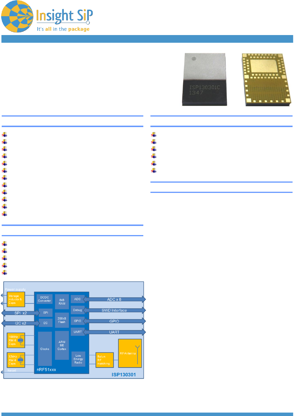
ISP130301
Bluetooth Low Energy Module
with Integrated Antenna
Key Features
Single Mode BLE v4.0 Slave or Master
Proprietary 2.4 GHz protocols
Based on Nordic Semiconductor nRF51 family
2.4GHz low energy RF Transceiver
32bit ARM Cortex M0 CPU with 256kB Flash
Analog and Digital peripherals
Ultra Low Power Consumption
Single 2.1 to 3.6 V supply
Very small size 8.0 x 11.0 x 1.2 mm
Temperature -25 to 75 °C
Fully integrated RF matching and Antenna
Integrated 16 MHz and 32.768 kHz Clocks
Certifications
FCC certification pending
CE certification pending
IC certification pending
Bluetooth SIG certified
RoHS compliant
Applications
Space constrained BLE Slave Devices
Sport and fitness sensors
Health care sensors
Out of Range (OOR) sensors
Personal User Interface Devices (PUID)
Remote controls
General Description
This module is based on nRF51822 Nordic
Semiconductor 2.4GHz wireless System on Chip
(SoC) integrating a 2.4 GHz transceiver, a 32 bit
ARM Cortex™-M0 CPU, a flash memory, and
analog and digital peripherals. It can support BLE
and a range of proprietary 2.4 GHz protocols, such
as Gazell from Nordic Semiconductor.
Fully qualified BLE stacks for nRF51822 are
implemented in the S100 series of SoftDevices
which can be freely downloaded. ISP130301 can
then be used in Master and Slave modes for BLE
and for both ends of other proprietary protocols.
The ANT protocol can be handled on request.
The module is specifically designed for both PC
peripherals and ultra low power applications such
as sports and wellness sensors. Ultra low power
consumption and advanced power management
enables battery lifetimes up to several years on a
coin cell battery. Even though its very small size
8x11x1.2mm, the module integrates decoupling
capacitors, 16 MHz and 32 kHz crystals, load
capacitors, DC-DC converter, RF matching circuit
and antenna in addition to the wireless SoC.
The module forms a standalone BLE node
for which only the addition of a suitable DC power source is necessary for proximity or Out of Range
applications. Sensor applications require only the further addition of the appropriate sensors. As the
module has several end applications, the antenna was designed to be compatible with several ground
plane sizes such as USB dongle or cell phone.
June 30, 2014
Page 2/14
Document Ref: isp_ble_DS130301_R5
Insight SiP – Green Side – 400 avenue Roumanille – BP 309 – 06906 Sophia-Antipolis Cedex – France – www.insightsip.com
The information contained in this document is the property of Insight SiP and should not be disclosed to any third party without written permission.
Specification subject to change without notice.
BLE MODULE
ISP130301
Contents
1. Electrical Specifications ........................................................................................................... Page 1-2
2. RF Performances .................................................................................................................... Page 1-6
3. Product Development Tools .................................................................................................... Page 1-9
4. Mechanical Outlines .............................................................................................................. Page 1-10
5. Quality & User Information ..................................................................................................... Page 1-13
6. Packaging & Storage ............................................................................................................. Page 1-14
1. Electrical Specifications
Electrical Performance
The specifications of the module follow those of the nRF51822. The following high level parameters are
given for the module.
The operating temperature range is -25 to +75 °C with the following performances.
Parameter
Value
Unit
Supply voltage
Supply Voltage
2.1 to 3.6
V
Current consumption
Static levels
Peak current, receiver active (supply at 2.1V)
12.6
mA
Peak current,
transmitter active +4 dBm Output Power
16
mA
Peak current,
transmitter active 0 dBm Output Power
10.5
mA
Current drain, connection-less state
0.5
µA
Current drain between connection events
2.3
µA
The EUT is intended to be supplied by a current limited power source.
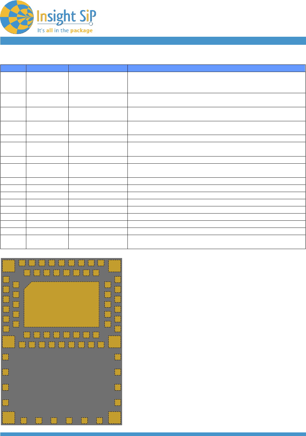
Pin Assignment
The module uses an LGA format with a double row of pads on a 0.65 mm pitch. The pad layout follows
the QFN Jedec standard for 2 row LGA parts.
Pads 1 thru 56 are signal pins 0.4 x 0.4 mm, Pad 57 is an exposed metal pad that is connected to
ground. The NC pads are 0.8 x 0.8 or 0.4 x 0.4 mm and are to be connected to isolated metal pads on
the application PCB for mechanical stability and reliability (drop test).
June 30, 2014
Page 3/14
Document Ref: isp_ble_DS130301_R5
Insight SiP – Green Side – 400 avenue Roumanille – BP 309 – 06906 Sophia-Antipolis Cedex – France – www.insightsip.com
The information contained in this document is the property of Insight SiP and should not be disclosed to any third party without written permission.
Specification subject to change without notice.
BLE MODULE
ISP130301
Pin
Name
Pin function
Description
1
P0_07
Digital I/O
General purpose I/O pin
2
NC
Not Connected
Isolated pad on application PCB for mechanical stability
3
P0_09
Digital I/O
General purpose I/O pin
4
NC
Not Connected
Isolated pad on application PCB for mechanical stability
5
P0_13
Digital I/O
General purpose I/O pin
6
NC
Not Connected
Isolated pad on application PCB for mechanical stability
7
P0_19
Digital I/O
General purpose I/O pin
8
NC
Not Connected
Isolated pad on application PCB for mechanical stability
9
P0_17
Digital I/O
General purpose I/O pin
10
NC
Not Connected
Isolated pad on application PCB for mechanical stability
11
P0_20
Digital I/O
General purpose I/O pin
12
VSS
Ground
Should be connected to ground plane on application PCB
13
NC
Not Connected
Isolated pad on application PCB for mechanical stability
14
VSS
Ground
Should be connected to ground plane on application PCB
15
NC
Not Connected
Isolated pad on application PCB for mechanical stability
16
VSS
Ground
Should be connected to ground plane on application PCB
17
NC
Not Connected
Isolated pad on application PCB for mechanical stability
18
VSS
Ground
Should be connected to ground plane on application PCB
19
NC
Not Connected
Isolated pad on application PCB for mechanical stability
20
VSS
Ground
Should be connected to ground plane on application PCB
21
NC
Not Connected
Isolated pad on application PCB for mechanical stability
22
VSS
Ground
Should be connected to ground plane on application PCB
23
VSS
Ground
Should be connected to ground plane on application PCB
24
OUT_MOD
Module I/O
This pin is the RF I/O pin of the BLE module. It should be connected
to Pin 26 OUT_ANT for normal operation. During certification the pin
may be connected via to an RF connector for module measurement
using a Bluetooth test setup.
25
VDD_PA
PA supply
PA supply indicates Transmit mode (Active High)
26
OUT_ANT
Antenna I/O
This pin is connected to the internal antenna. It should be
connected to Pin 24 OUT_MOD for normal operation. During
certification the pin may be connected to an RF connector for
antenna measurement
27
VSS
Ground
Should be connected to ground plane on application PCB
28
VSS
Ground
Should be connected to ground plane on application PCB
29
VCC_nRF
Power
Power supply (2.1 – 3.6V). VDD in nRF51822 doc.
30
VSS
Ground
Should be connected to ground plane on application PCB
31
SWDCLK
Digital Output
HW debug and flash programming I/O
32
P0_18
Digital I/O
General purpose I/O pin
33
SWDIO-
nRESET
Digital I/O
System reset (active low). Also HW debug and flash
programming I/O
34
P0_16
Digital I/O
General purpose I/O pin
35
P0_15
Digital I/O
General purpose I/O pin
36
P0_14
Digital I/O
General purpose I/O pin
37
P0_12
Digital I/O
General purpose I/O pin
38
P0_10
Digital I/O
General purpose I/O pin
39
P0_11
Digital I/O
General purpose I/O pin
40
P0_05-AIN6
Digital I/O
Analog input
General purpose I/O pin
ADC input 6
June 30, 2014
Page 4/14
Document Ref: isp_ble_DS130301_R5
Insight SiP – Green Side – 400 avenue Roumanille – BP 309 – 06906 Sophia-Antipolis Cedex – France – www.insightsip.com
The information contained in this document is the property of Insight SiP and should not be disclosed to any third party without written permission.
Specification subject to change without notice.
BLE MODULE
ISP130301
NC NC
30
39
29
NCNC
55 53 51 49 47 45 43 41
56 54 52 50 48 46 44 42
10
8
6
4
2
11
9
7
5
3
1
57
EP GND
NC NC
NC
NC
NC
NC
NC NC NC NC NC NC
NC
NC
NC
NC
12 28
40
13
14
15
16
17
18
19
20
21
22
23
24
25
26
27
31
32
33
34
35
36
37
38
Pin
Name
Pin function
Description
41
P0_06-AIN7-
AREF1
Digital I/O
Analog input
Analog input
General purpose I/O pin
ADC input 7
ADC Reference voltage
42
P0_03-AIN4
Digital I/O
Analog input
General purpose I/O pin
ADC input 4
43
P0_04-AIN5
Digital I/O
Analog input
General purpose I/O pin
ADC input 5
44
P0_01-AIN2
Digital I/O
Analog input
General purpose I/O pin
ADC input 2
45
P0_31
Digital I/O
General purpose I/O pin
46
P0_02-AIN3
Digital I/O
Analog input
General purpose I/O pin
ADC input 3
47
P0_30
Digital I/O
General purpose I/O pin
48
P0_00-
AREF0
Digital I/O
Analog input
General purpose I/O pin
ADC Reference voltage
49
P0_29
Digital I/O
General purpose I/O pin
50
P0_28
Digital I/O
General purpose I/O pin
51
P0_24
Digital I/O
General purpose I/O pin
52
P0_23
Digital I/O
General purpose I/O pin
53
P0_21
Digital I/O
General purpose I/O pin
54
P0_22
Digital I/O
General purpose I/O pin
55
P0_25
Digital I/O
General purpose I/O pin
56
P0_08
Digital I/O
General purpose I/O pin
57
GND_EP
Ground
Exposed metal pad. Should be connected to ground plane on
application PCB
ISP130301pad placement and pin assignment
for the LGA QFN package
TOP VIEW
June 30, 2014
Page 5/14
Document Ref: isp_ble_DS130301_R5
Insight SiP – Green Side – 400 avenue Roumanille – BP 309 – 06906 Sophia-Antipolis Cedex – France – www.insightsip.com
The information contained in this document is the property of Insight SiP and should not be disclosed to any third party without written permission.
Specification subject to change without notice.
BLE MODULE
ISP130301
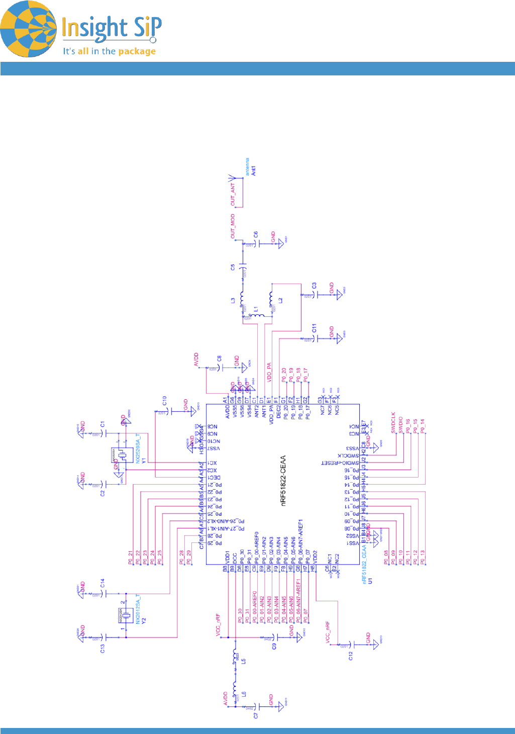
Electrical Schematic
Electrical schematic showing ISP130301 module connections
June 30, 2014
Page 6/14
Document Ref: isp_ble_DS130301_R5
Insight SiP – Green Side – 400 avenue Roumanille – BP 309 – 06906 Sophia-Antipolis Cedex – France – www.insightsip.com
The information contained in this document is the property of Insight SiP and should not be disclosed to any third party without written permission.
Specification subject to change without notice.
BLE MODULE
ISP130301
2. RF Performances
RF Specifications according to standards
Parameter
Value
BT V4
Std limit
Unit
Condition
Output Power
-20 to +4
-20 to 10
dBm
Channels
0 to 39
RF Frequency tolerance
Better than
+/-20
+/- 50
Hz
Channels
0 to 39
Rx sensitivity
-93
-70
dBm
Level for BER
<0,1% ideal Tx
Max range
> 200
m
Open field @1m
height
EIRP
4.6
dBm
Antenna Gain
0.6
dBi
Rx sensitivity
51.4
dBµV/m
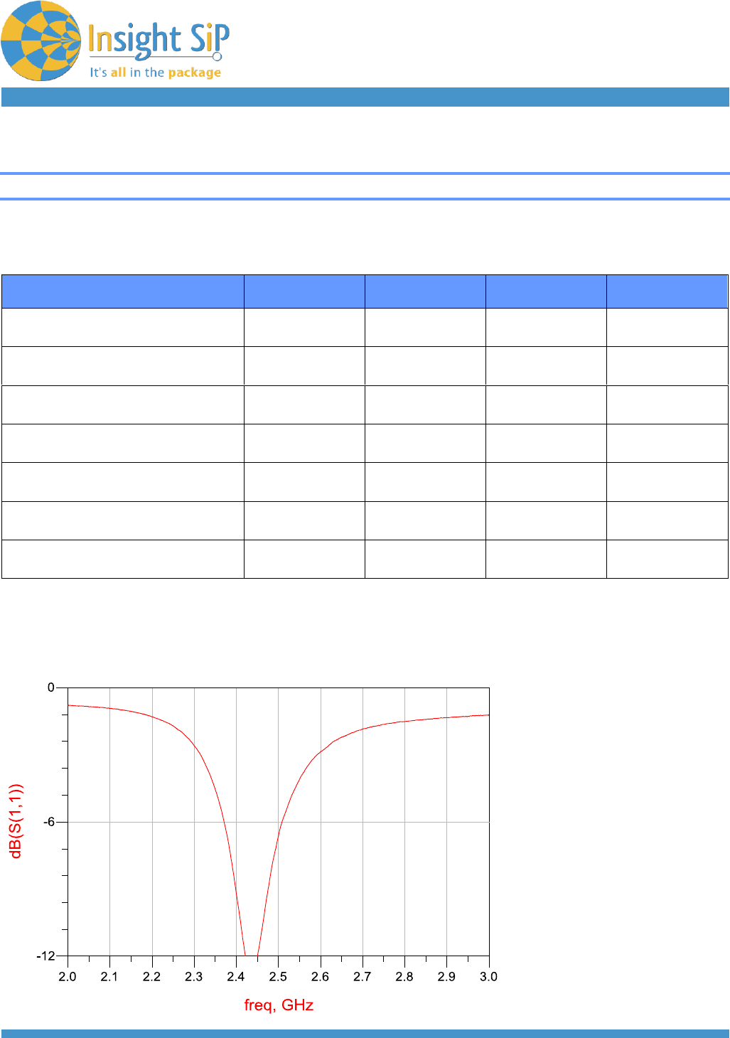
Typical Antenna Return Loss
Module mounted on a USB dongle ground plane

June 30, 2014
Page 7/14
Document Ref: isp_ble_DS130301_R5
Insight SiP – Green Side – 400 avenue Roumanille – BP 309 – 06906 Sophia-Antipolis Cedex – France – www.insightsip.com
The information contained in this document is the property of Insight SiP and should not be disclosed to any third party without written permission.
Specification subject to change without notice.
BLE MODULE
ISP130301
Radiation Pattern in 3 planes
Module mounted on a USB dongle ground plane
Ground Plane Effect Simulation
-40
-30
-20
-10
0
gain (dBi) @ 2.45GHz
z=0°
=90°
y
x
y
z
-40
-30
-20
-10
0
gain (dBi) @ 2.45GHz
z=0°
=90°
x
x
y
z
-40
-30
-20
-10
0
gain (dBi) @ 2.45GHz
=0°
=90°
y
x
x
y
z
USB dongle
ground plane
(size : 18 x 30 mm²)
Cell phone config 1
ground plane
(size : 40 x 100 mm²)
Cell phone config 1 with
side ground plane
(size : 40 x 100 mm²)

June 30, 2014
Page 8/14
Document Ref: isp_ble_DS130301_R5
Insight SiP – Green Side – 400 avenue Roumanille – BP 309 – 06906 Sophia-Antipolis Cedex – France – www.insightsip.com
The information contained in this document is the property of Insight SiP and should not be disclosed to any third party without written permission.
Specification subject to change without notice.
BLE MODULE
ISP130301
Cell phone config 2 with
side ground plane
(size : 40 x 100 mm²)
Cell phone config 3 with
side ground plane
(size : 40 x 100 mm²)

June 30, 2014
Page 9/14
Document Ref: isp_ble_DS130301_R5
Insight SiP – Green Side – 400 avenue Roumanille – BP 309 – 06906 Sophia-Antipolis Cedex – France – www.insightsip.com
The information contained in this document is the property of Insight SiP and should not be disclosed to any third party without written permission.
Specification subject to change without notice.
BLE MODULE
ISP130301
3. Product Development Tools
Interface
ISP130301 integrates a full microprocessor interface with up to 32 General Purpose I/O pins (GPIO) and
several functions (2 x SPI, 2 x I2C, UART, 8 x ADC, SWDIO interface).
Hardware
The following development kit is recommended for using and testing ISP130301 module:
Insight SiP Development Kit (ISP130301-DK1), need to be purchased separately
Development Tools and Software
The following development tools and software are recommended for using and testing ISP130301
module:
Nordic Semiconductor nRFgo Studio (downloadable from www.nordicsemi.com after purchasing
ISP130301-DK1)
Nordic Semiconductor Master Control Panel (downloadable from www.nordicsemi.com after
purchasing ISP130301-DK1)
Keil MDK-ARM Lite (downloadable for free from https://www.keil.com/demo/eval/arm.htm)
Segger J-Link Lite (downloadable for free from http://www.segger.com/jlink-software.html)
S100 nRF51822 SoftDevice: fully qualified Bluetooth low energy stacks for nRF51822 integrated in
ISP130301 module. The S100 series of SoftDevices (object code, no source) can be downloaded
from www.nordicsemi.com after purchasing ISP130301-DK1
nRF51 Software Development Kit (SDK): nRF51 SDK can be downloaded from www.nordicsemi.com
after purchasing ISP130301-DK1. It contains example of source codes applications (C language):
- Precompiled HEX files
- Source code
- Keil ARM project files
June 30, 2014
Page 10/14
Document Ref: isp_ble_DS130301_R5
Insight SiP – Green Side – 400 avenue Roumanille – BP 309 – 06906 Sophia-Antipolis Cedex – France – www.insightsip.com
The information contained in this document is the property of Insight SiP and should not be disclosed to any third party without written permission.
Specification subject to change without notice.
BLE MODULE
ISP130301
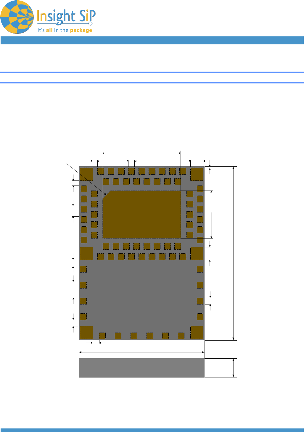
4. Mechanical Outlines
Mechanical Dimensions
Dimensional drawing for 8 x 11 x 1.2 mm, 57-Pad LGA Package
11 mm
8 mm
1.2 mm
0.65 mm
1.0 mm
0.275 mm
0.3 mm
0.1 mm
PIN 1 INDICATOR
C 0.3 mm
5 mm
3mm
0.4 mm
0.4 mm
0.4 mm
0.4 mm 0.8 mm
0.8 mm
0.4 mm
June 30, 2014
Page 11/14
Document Ref: isp_ble_DS130301_R5
Insight SiP – Green Side – 400 avenue Roumanille – BP 309 – 06906 Sophia-Antipolis Cedex – France – www.insightsip.com
The information contained in this document is the property of Insight SiP and should not be disclosed to any third party without written permission.
Specification subject to change without notice.
BLE MODULE
ISP130301
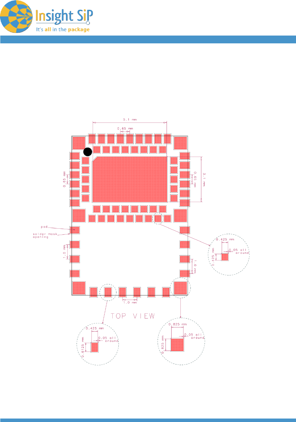
SMT Assembly Guidelines
Recommended PCB Land Pattern and Solder Mask layout

June 30, 2014
Page 12/14
Document Ref: isp_ble_DS130301_R5
Insight SiP – Green Side – 400 avenue Roumanille – BP 309 – 06906 Sophia-Antipolis Cedex – France – www.insightsip.com
The information contained in this document is the property of Insight SiP and should not be disclosed to any third party without written permission.
Specification subject to change without notice.
BLE MODULE
ISP130301
Antenna Keep-Out Zone
Recommended metal keep out areas for optimal antenna performance:
no metal, no traces and no components on any layer except mechanical LGA pads.

June 30, 2014
Page 13/14
Document Ref: isp_ble_DS130301_R5
Insight SiP – Green Side – 400 avenue Roumanille – BP 309 – 06906 Sophia-Antipolis Cedex – France – www.insightsip.com
The information contained in this document is the property of Insight SiP and should not be disclosed to any third party without written permission.
Specification subject to change without notice.
BLE MODULE
ISP130301
5. Quality & User information
USA – User information
This intends to inform how to specify the FCC ID of our module “ISP130301” on the product. Based on
the Public Notice from FCC, the host device should have a label which indicates that it contains our
module. The label should use wording such as: “Contains FCC ID: XXXXX-ISP130301”.
Any similar wording that expresses the same meaning may be used.
The label of the host device should also include the below FCC Statement. When it is not possible, this
information should be included in the User Manual of the host device:
“This device complies with part 15 of the FCC rules. Operation is subject to the following two conditions.
(1) This device may not cause harmful interference
(2) This device must accept any interference received, including interference that may cause undesired
operation.
Caution: Any Changes or modifications not expressly approved by the party responsible for compliance
could void the user’s authority to operate the equipment.”
CANADA – User information
This intends to inform how to specify the IC ID of our module “ISP130301” on the product. According to
Canadian standards “RSS-210” and “RSS-Gen”, the host device should have a label which indicates that
it contains our module.
The label should use wording such as: “Contains IC: XXXXXX-ISP130301”.
Any similar wording that expresses the same meaning may be used.
The label of the host device should also include the below IC Statement. When it is not possible, this
information should be included in the User Manual of the host device:
“This device complies with Industry Canada licence-exempt RSS standard(s). Operation is subject to the
following two conditions: (1) this device may not cause interference, and (2) this device must accept any
interference, including interference that may cause undesired operation of the device.
Cette notice nous informe comment spécifier le IC ID de notre module ISP130301. Selon les normes
Canadiennes "RSS-210" et "RSS-Gen", le dispositif doit avoir une étiquette mentionnant qu’il contient
notre module. L’étiquette doit être sous la forme : "IC :XXXXXX-ISP130301".
Tout libellé similaire exprimant le même sens peut être utilisé.
L’étiquette du dispositif devra également inclure la déclaration ci-dessous. Si cela n’est pas possible,
cette information devra être précisée dans le manuel de l’utilisateur :
Le présent appareil est conforme aux CNR d'Industrie Canada applicables aux appareils radio exempts
de licence. L'exploitation est autorisée aux deux conditions suivantes : (1) l'appareil ne doit pas produire
de brouillage, et (2) l'utilisateur de l'appareil doit accepter tout brouillage radioélectrique subi, même si le
brouillage est susceptible d'en compromettre le fonctionnement.”
June 30, 2014
Page 14/14
Document Ref: isp_ble_DS130301_R5
Insight SiP – Green Side – 400 avenue Roumanille – BP 309 – 06906 Sophia-Antipolis Cedex – France – www.insightsip.com
The information contained in this document is the property of Insight SiP and should not be disclosed to any third party without written permission.
Specification subject to change without notice.
BLE MODULE
ISP130301
6. Packaging & Storage
Package marking
I
S
P
1
3
0
3
0
1
C
Y
Y
W
W
ISP130301
Product number
C
Hardware version
YY
Two digit year number
WW
Two digit week number
Moisture Sensitivity
All plastic packages absorb moisture. During typical solder reflow operations when SMDs are mounted
onto a PCB, the entire PCB and device population are exposed to a rapid change in ambient
temperature. Any absorbed moisture is quickly turned into superheated steam. This sudden change in
vapor pressure can cause the package to swell. If the pressure exerted exceeds the flexural strength of
the plastic mold compound, then it is possible to crack the package. Even if the package does not crack,
interfacial delamination can occur.
Since the device package is sensitive to moisture absorption, it is recommended to bake the product
before assembly. The baking process for dry packing is 24 hours at 125°C.
ISP130301C
YYWW
IC
5 mm max