Instant Care 3000TX1 IC 3000 Wireless Pendant User Manual IC3000 Manual 1 9
Instant Care, Inc. IC 3000 Wireless Pendant IC3000 Manual 1 9
UserManual.wiki
>
Instant Care
>
3000TX1 User Manual
>
Users Manual
Contents
1.
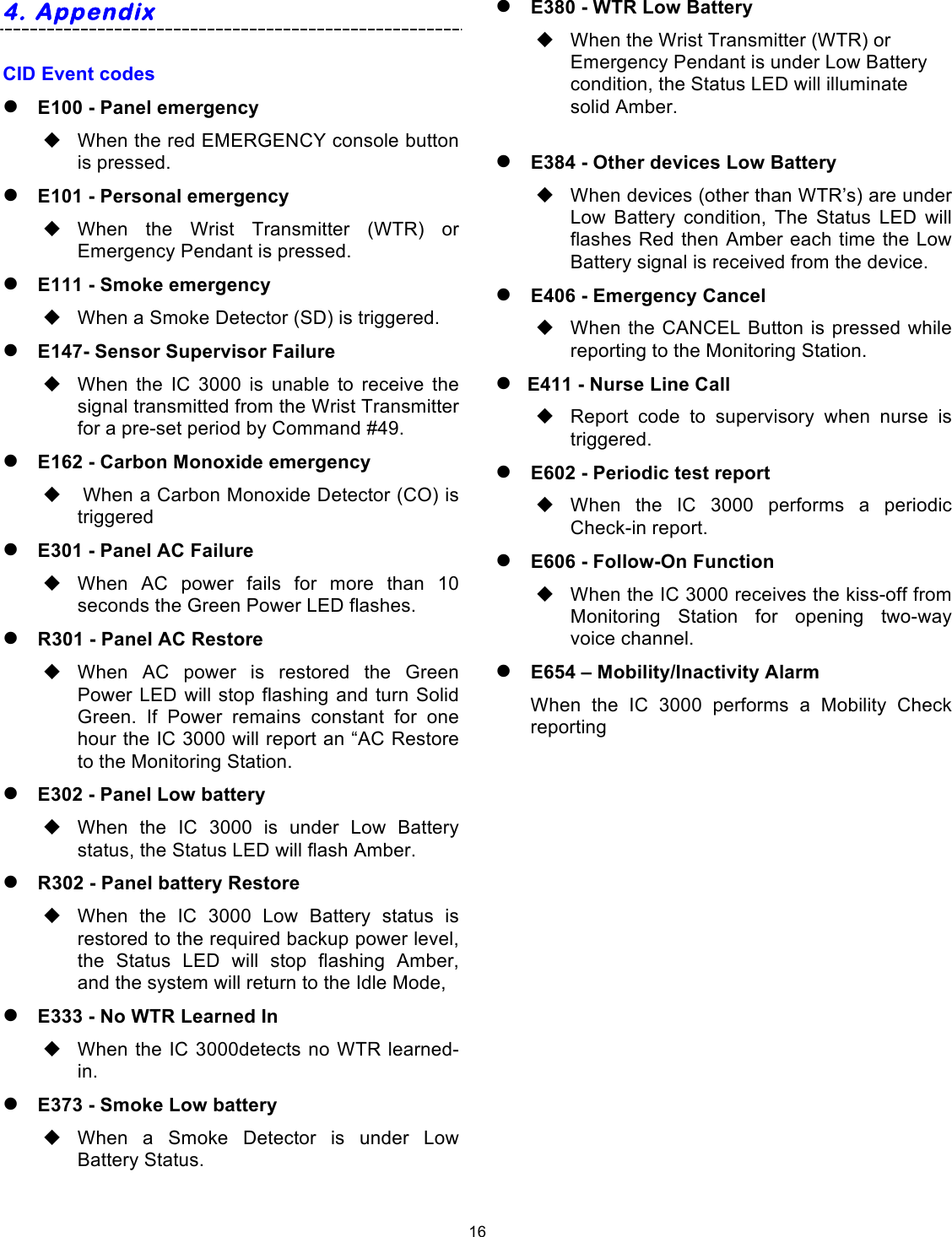
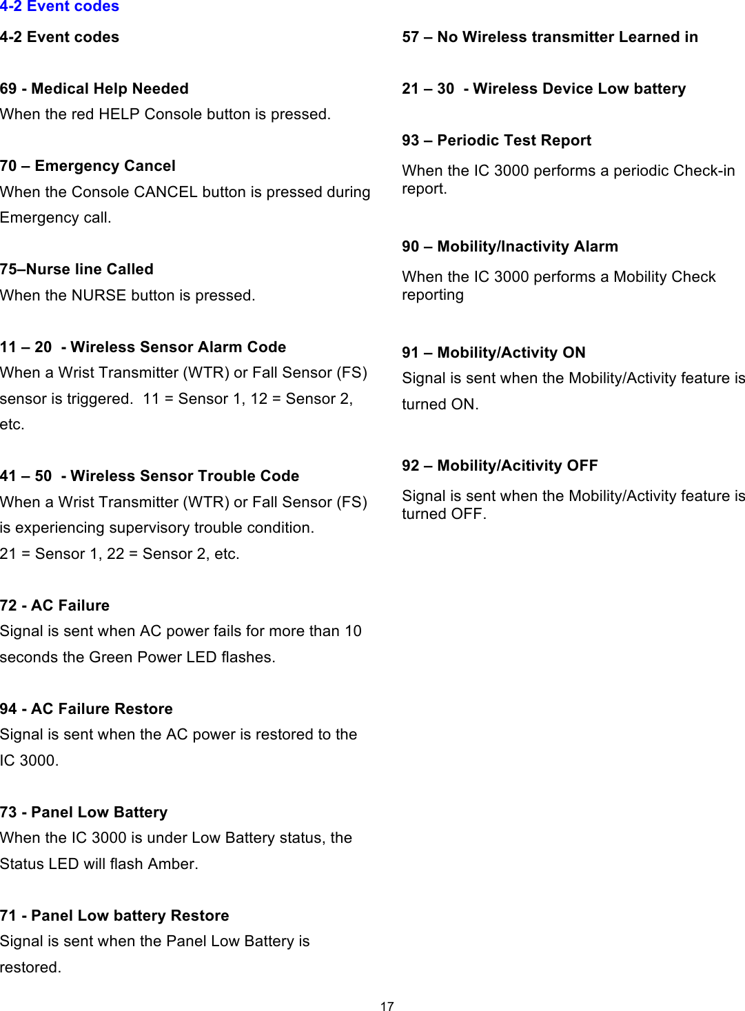
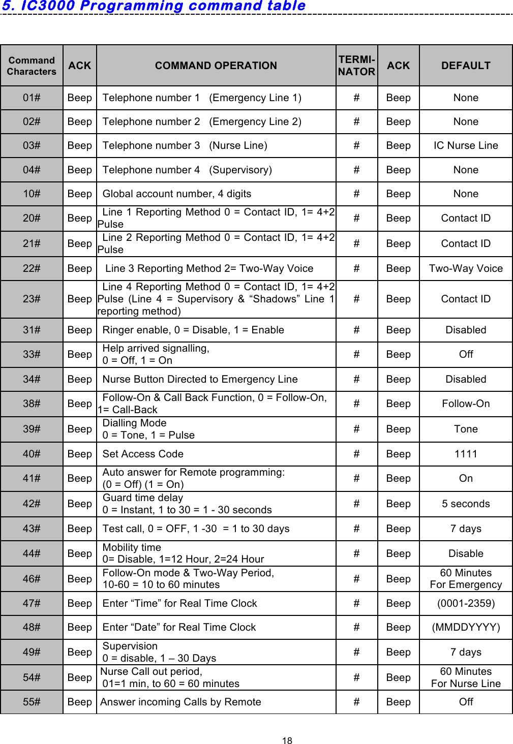
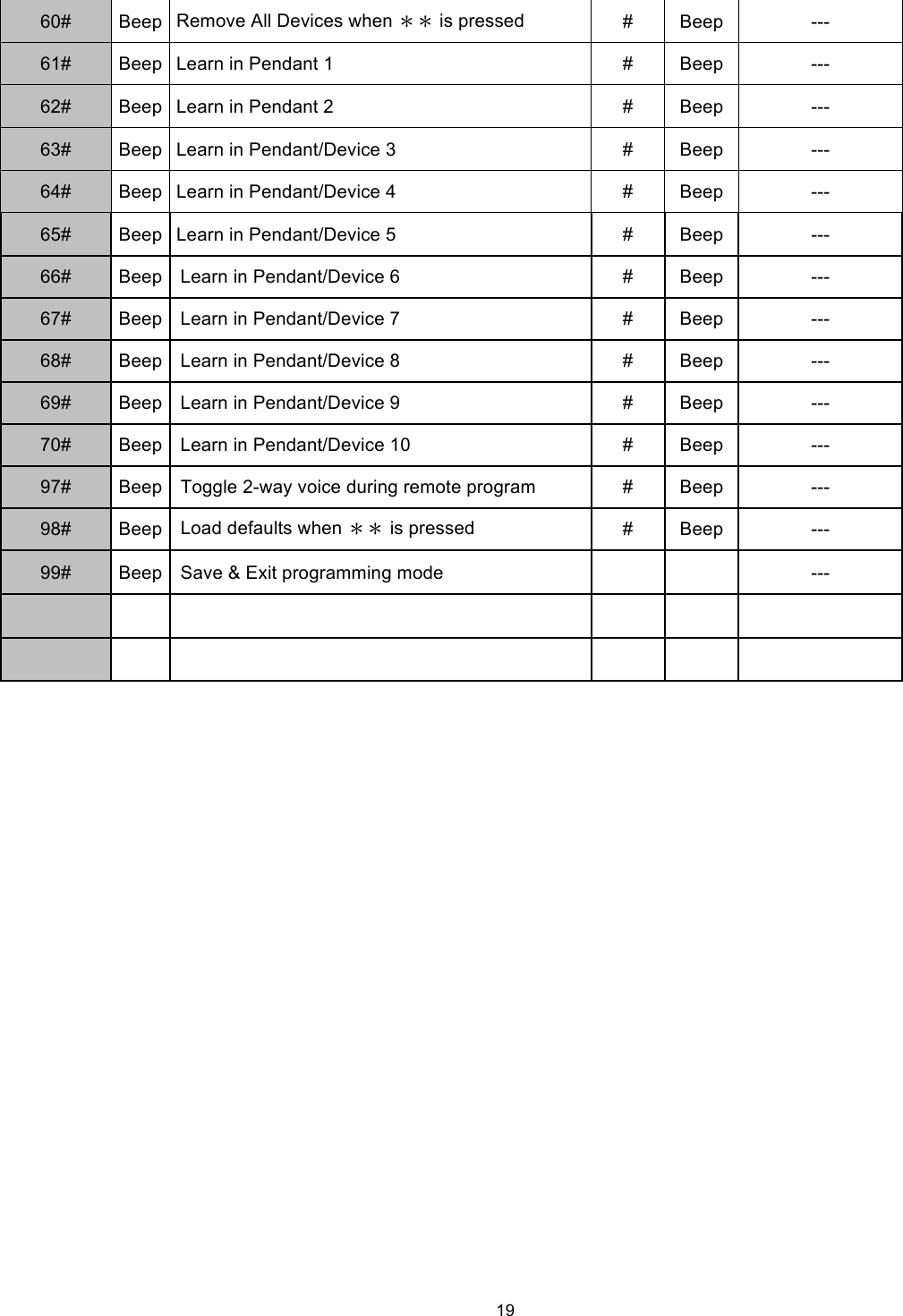
Users Manual
2.
Users Guide
Users Manual
Navigation menu
Upload a User Manual
Namespaces
Wiki Guide
HTML
PDF
Info
Views
User Manual
Discussion / Help
Navigation