Instant Care 3000TX1 IC 3000 Wireless Pendant User Manual IC3000 Manual 1 9
Instant Care, Inc. IC 3000 Wireless Pendant IC3000 Manual 1 9
Contents
- 1. Users Manual
- 2. Users Guide
Users Manual

Table of Contents
IC 3000 MANUAL
- Installation
- Programming
- Operation
10-24-2012
Ver. 1.9
1
Table&of&Contents&
1.#Overview&............................................................&2&
!"!#$%&'()*+),-#,.#/,-&,0%#""""""""""""""""""""""""""""""""""""""""""""""""""""#1#
!"1#2,3%(#4-5#64++%(7#8-.,(94+),-#""""""""""""""""""""""""""""""""""#1#
!":#$%&'()*+),-#,.#2%-54-+#"""""""""""""""""""""""""""""""""""""""""""""""""""#1#
!";#<=$#>%*,(+)-?#/@4(+#""""""""""""""""""""""""""""""""""""""""""""""""""""""""#;#
!"A#/@%'BC,..#<)&+#"""""""""""""""""""""""""""""""""""""""""""""""""""""""""""""""""""""""#;#
2.#System#Operations#&#Reporting&..........................&5&
1"!#D-&3%(EF4-?CG*#8-',9)-?#2@,-%#/400&#"""""""""""""""""#A#
1"1#D/#2,3%(#H4G0+E>%&+,(%#I#>%*,(+)-?#""""""""""""""""""""""#A#
1":#/,-&,0%#64++%(7#""""""""""""""""""""""""""""""""""""""""""""""""""""""""""""""""""#A#
1";#2%-54-+EJ9,B%#$%+%'+,(EK+@%(#$%L)'%&#<,3#
64++%(7#"""""""""""""""""""""""""""""""""""""""""""""""""""""""""""""""""""""""""""""""""""""""""""#A#
1"A#M,#2%-54-+#2(%&%-+#""""""""""""""""""""""""""""""""""""""""""""""""""""""""""#N#
1"N#DG+,94+)'#/@%'BC)-#>%*,(+#O2%(),5)'#P%&+#/400Q#""#N#
1"R#<%4(-)-?#>%9,+%&#!#I#1#"""""""""""""""""""""""""""""""""""""""""""""""""#N#
1"S#/,99G-)'4+),-#H,(94+&#""""""""""""""""""""""""""""""""""""""""""""""""#N#
1"T#P%0%*@,-%#<)-%#J%)UG(%#"""""""""""""""""""""""""""""""""""""""""""""""""""#N#
1"!V#2@,-%#<)-%#$%+%'+),-#""""""""""""""""""""""""""""""""""""""""""""""""""""#N#
1"!!#MG(&%#/400#"""""""""""""""""""""""""""""""""""""""""""""""""""""""""""""""""""""""""""#R#
1"!1#>4-?%#P%&+#""""""""""""""""""""""""""""""""""""""""""""""""""""""""""""""""""""""""""#R#
1"!:#64'BG*#64++%(7#J3)+'@#"""""""""""""""""""""""""""""""""""""""""""""""""#R#
3.#Programming#Instructions&...................................&8&
:"!#<,'40#2(,?(499)-?#""""""""""""""""""""""""""""""""""""""""""""""""""""""""""#S#
:"1#>%9,+%#2(,?(499)-?#"""""""""""""""""""""""""""""""""""""""""""""""""""""#S#
:":#2(,?(499)-?#P@%#8/#:VVV#""""""""""""""""""""""""""""""""""""""""""""#T#
4.#Appendix&..........................................................&16&
5.#IC#3000#Programming#Command#Table&..............&18&
2
1. Overview
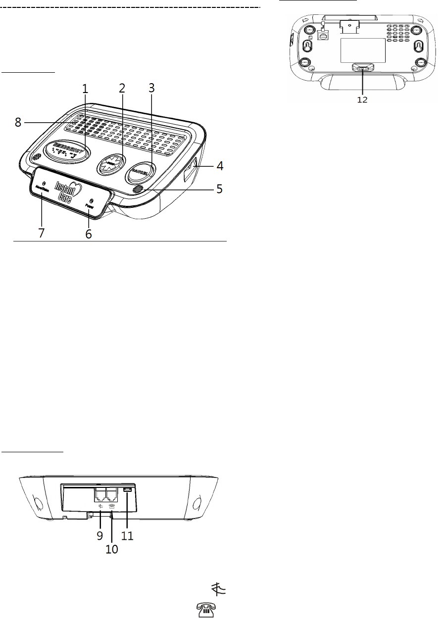
1.1 Description of Console (P/N: IC3000V01)
TOP VIEW
1. EMERGENCY button
2. NURSE button
3. CANCEL button
4. Volume Control
5. Microphone
6. POWER LED
7. STATUS LED
8. Speaker
REAR VIEW
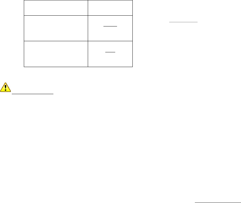
9. Line in jack (plug into tel. wall jack)
10. Phone jack (plug into user’s tel.)
11. USB Port (for programming only)
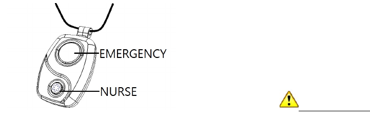
BOTTOM VIEW
12. Backup battery switch
Locating a suitable position for the Console.
• The console should be placed on a flat surface
such as a countertop or table, and located in an
area that is easily accessible.
• The console requires main power and a
constant telephone connection.
• The console should be located in the same
room as the telephone jack it is connected to.
• The console should not be placed in a damp
location such as a bathroom.
• The console should not be placed close to any
heat source, such as direct sunlight, microwave
oven, which can reduce signal strength.
• The console should not be located alongside
other radio transmitting devices such as a
mobile phone, cordless phone, or wireless
computer network (Wi-Fi) devices.
1.2 Power and Battery Information
• Primary Voltage Input: 100-240VAC 50/60
Hz 0.2A; and Output 12VDC: 500mA.
• Rechargeable battery (Ni-MH, 7.2V, 700mAh) is
located inside the console, which serves as a
backup in case of a power failure.
• When the battery is fully charged, it serves as a
backup power source for a period of at least
24hrs. It can take up to 48hrs to fully charge the
battery. 24hr test performed in the toggle mode
(1 way voice).
• Battery switch (located at the bottom of console)
is set to ON by default. If switched to OFF, the
battery will be disconnected and will not be
charged, nor will it serve as a backup power
source when AC power is missing.
3
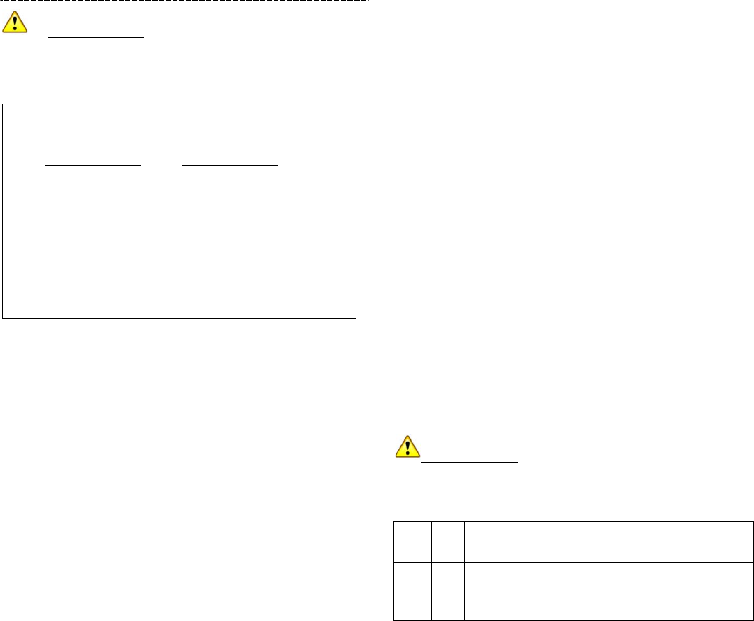
1.3 Description of Pendant (P/N: IC3000TX1)
1. EMERGENCY button (hold the RED button
for 15 sec. to enable pendant supervisory,
hold the WHITE button for 15 sec. to disable
pendant supervisory)
2. NURSE button
Pendant Electrical Specifications
Frequency: 433.92 Mhz
• Battery: CR2032, 3V 230mAh
• Battery life: Typical life expectancy of 5 yrs at an
average use rate of one activation per day.
• Open Field Range: Approximately 600 Ft.
IMPORTANT: It is recommended that the user(s)
run a pendant test each week to ensure that the
console is properly functioning.

4
1.4 LED Reporting Chart
1.5 Check-off List
System Condition
Status LED
Power LED
AC power fault (No AC power)
Flashes Green
Console power ON
Solid Green
Emergency call
Solid Red
Nurse call
Solid Blue
Console battery low/failure
Flashes Amber
Pendant low battery
Solid Amber
Learning mode
Solid Purple
Programming mode
Flashes Purple
Battery switch is OFF
Flashes Red
Account # empty / No Line1 / No pendant
Flashes Red then Purple
Other devices low battery
Flashes Red then Amber
Phone line failure
Flashes Red then Blue
Verified
Items
☐
AC adaptor is plugged in securely
☐
Telephone line is plugged into the GREEN “Line-In port”
☐
User's telephone is plugged in the RED “telephone port”
☐
Battery switch is in the ON position
☐
Turn ON pendant check-in feature
☐
Perform test call to Monitoring Station by pressing the Red Button on the pendant
☐
Remind user to perform weekly pendant test
☐
Perform Nurse Call
☐
Ensure that the Power LED is ON and the Status LED is OFF
NOTE: This equipment has been tested and found to comply with the limits for a Class B digital device,
pursuant to part 15 of the FCC Rules. These limits are designed to provide reasonable protection against harmful
interference in a residential installation. This equipment generates, uses and can radiate radio frequency energy
and, if not installed and used in accordance with the instructions, may cause harmful interference to radio
communications. However, there is no guarantee that interference will not occur in a particular installation. If this
equipment does cause harmful interference to radio or television reception, which can be determined by turning
the equipment off and on, the user is encouraged to try to correct the interference by one or more of the following
measures:
—Reorient or relocate the receiving antenna.
—Increase the separation between the equipment and receiver.
—Connect the equipment into an outlet on a circuit different from that to which the receiver is connected.
—Consult the dealer or an experienced radio/TV technician for help.

5
2. System Operations & Reporting
2.1 Answer / Hang-up Incoming Phone Calls
Answering a call:
• To enable this feature, please refer to Command
55, (default is OFF).
• User can ONLY answer an incoming phone call
by pressing the RED button on the pendant.
The buttons on console are NOT able to answer
calls.
• Once the console detects a pendant button
press, it will establish a two-way voice
communication (similar to a speaker phone).
Hanging up a call:
• At the end of a call, user can press the RED
button on the pendant or the CANCEL button on
the console.
• The maximum duration for an incoming phone
call is 60 minutes (See Command 54). A timer
will start after the system establishes a two-way
voice communication.
• The console will disconnect the call when the
timer expires. During the call, the console will
emit a beep to indicate when there is 20
seconds and another beep when there is 10
seconds left on the timer. The call can be
extended for duration set by (Command 54) by
having the caller press any DTMF key (except 9)
on their handset.
• The caller can end the call by pressing “9” on
their handset.
2.2 AC Power Fault / Restore & Reporting
• In the event of a power failure, the console’s
GREEN power LED will flash until the power is
restored representing a visual warning for the
user.
• If the power IS restored within 1 hour, the
GREEN power LED will stop flashing, the
system will resume normal operation. No
reports will be transmitted to the Monitoring
Station.
• If the power is NOT restored within 1 hour, the
console will transmit an AC Power Fault Report
to the Monitoring Station.
• Once power has been restored, and stays on for
at least 1 hour, the console will transmit an AC
Power Restore Report to the Monitoring
Station.
2.3 Console Battery
• It can take up to 48 hours to fully charge the
battery. When the battery is fully charged, it
serves as a back-up power source for a period
of at least 24 hours. Once the battery is fully
charged, it will continuously check its battery
status.
• In the event the STATUS LED begins to flash
AMBER, this will indicate a console battery
low/failure. The console will transmit a Low
Battery Console report (See Section 4.0) every
24 hours to the Monitoring Station.
• Once the battery voltage is restored, the console
will transmit a Battery Restore report to the
Monitoring Station and the STATUS LED will
stop flashing. If the STATUS LED continues to
flash, this indicates battery failure.
2.4 Pendant / Smoke Detector / Other Devices
Low Battery
• If the console receives a low battery signal from
any learned wireless pendants / detectors /
devices, the console will transmit a
corresponding low battery report to the
Monitoring Station.
• The console will transmit a new report every 24
hours as long as the condition exists. The
STATUS LED will illuminate until the fault
condition is cleared. (See Section 1.4 for LED
Reporting Chart)
• When a faulty battery is replaced the console
will transmit a Battery Restore report to the
Monitoring Station for that particular device.
IMPORTANT: Portable devices such as a
pendant must be within the RF range for the console
to receive the low battery signal and report the event
to the Monitoring Station.

6
2.5 No Pendant Present
• If a pendent has not been learned into Location
#1 or #2 (See Commands 61 & 62) within 30
min after powering up, the console will send a
No Pendant Learned in report to the Monitoring
Station and repeat it every 24 hours thereafter,
until a pendant is successfully learned in.
2.6 Automatic Check-in Report (Periodic Test Call)
• The console will send a check-in report (Periodic
test call) to the Monitoring Station (see
Command 43). This allows the Monitoring
Station or those involved in managing the users
well being to see that the system is functioning
properly.
2.7 Learning Remotes 1 & 2
The system allows you to learn pendants 1 & 2
(Same as Commands 61 & 62) into the console
without having to go into Programming mode.
Follow the steps below for learning remotes 1 & 2:
Step 1. Press and hold the NURSE & CANCEL
buttons (approx. 5 sec.) until the console
emits a beep and STATUS LED illuminates
PURPLE.
Step 2. Learn Remote 1: press and hold the
EMERGENCY button on the console.
Learn Remote 2: press and hold the
NURSE Button on the console.
Step 3. The status LED should now indicate either
Green or Red.
Status LED
Definition
Green
Zone is available (Press either pendant button
learn)*
Red
Zone is occupied (Enter another zone or press
CANCEL to remove)
Flashing
purple
In programming mode
Step 4.
Zone is available: within 20 seconds of Step 2, press
the RED* pendant button.
Zone is occupied:
Desired action
Within 20 seconds of Step 3:
Change to a
different Zone
Enter a different Command (different
Zone number).
Remove current
device
Press CANCEL on the console until
system emits a short beep and the
Status LED turns green.
Remove current
device and learn
new device
Press CANCEL on the console until the
system emits a short beep and the
Status LED turns green, then press
RED pendant button.
Step 5. Once a signal is received in the given time
frame, the Status LED on the console will
illuminate RED and an audible beep will be
heard.
Step 6. To exit LEARNING MODE, press the
CANCEL button.
* If no signal is received within 2 minutes after
entering LEARNING MODE, the console will exit.
2.8 Communication Formats
Operator’s control during a call:
• TWO-WAY mode: Press (2) for a Two-Way
conversation.
• TALK ONLY mode: Press (1) for operator Talk
Only Mode.
• LISTEN ONLY mode: Press (3) for operator
Listen Only Mode.
• TERMINATING A CALL: Press (9) to disconnect
any call.
2.9 Telephone Line Seizure
• If a phone is in use that is connected to the
console, and the EMERGENCY button is
pressed, the console will seize the line to place
a call.
• If a phone is in use that is NOT connected to the
console, the line seizure feature will not operate.
2.10 Phone Line Detection
• If the console does NOT detect the phone line
(no dial tone from telephone company, line
failure, etc…). The STATUS LED will flash RED
then BLUE until the phone line is
connected/restored.
• If the Emergency or Nurse button is pressed

7
during the line failure, the console will emit a
voice prompt “Phone line trouble”.
• If the Emergency button is pressed during the
line failure, the console will queue the call and
dial the Monitoring Station after the phone line is
restored.
• All reporting messages will be queued and
transmitted to the Monitoring Station after the
phone line is restored.
2.11 Nurse Call
This function is only available when Command #3 is
programmed.
Step 1. Press the NURSE* button on the console.
Step 2. The console will emit a voice prompt
“Calling nurse line”. The system will begin
dialing the phone number entered in
Command #3.
Step 3. The system will establish a two-way
communication between the nurse and the
console. A timer will start (See Command
54) allowing maximum duration for this
connection.
Step 4. The console will disconnect the call when
the timer expires. During the call, the
console will emit a beep to indicate when
there is 20 seconds and another beep when
there is 10 seconds left on the timer. The
beep can only be heard on the nurse side.
The call can be extended for duration set by
(Command 54) by having the nurse press
any DTMF key (except 9) on their handset.
Step 5. To end the call, user may press the
CANCEL button on the console.
IMPORTANT: After the nurse call, the system
will transmit a report to the Monitoring Station. (The
system generates CID event code 411 as Nurse Call
Placed.)
* If CANCEL button was pressed before or after the
call was established, it will cancel/hang up the call.
* If RED Emergency button (console or pendant) was
pressed at any time during the nurse call, the nurse
call will be terminated and Emergency call will be
placed.
2.12 Range Test
After the pendants (or any wireless device) have
been learned in to the console, perform a range test
to determine the operating range of the devices.
Step 1. Place the console at desirable location in
the house then power it up.
Step 2. Press and hold the NURSE & CANCEL
buttons (approx. 5 sec.) until the console
emits a beep and Status LED illuminates
PURPLE.
Step 5. Press and release the Red button on the
pendant. When in range, the console will
emit a beep each time the button is
pressed/transmission received.
Step 6. To exit Range test mode, press the
CANCEL button. The console will
automatically exit after 30 sec. if no signal
is received.
2.13 Backup Battery Switch
• Battery backup switch is located at the bottom of
the console. The switch should be set to the
ON position at all times, except when
instructed by installer/Monitoring Station.
• When the switch is set to the OFF position, the
internal backup battery will NOT charge and
STATUS LED on the console will flash RED until
switch is to ON. The Real-Time Clock of the
system will reset. A switch OFF report will be
sent every 24hrs to the Monitoring Station.
• When the battery is fully charged, it serves as a
back-up power source for a period of at least 24
hours. It can take approximately 48 hours to fully
charge the battery.
8
3. Programming Instructions
IMPORTANT: PLEASE READ THE
FOLLOWING BEFORE PROCEEDING TO THE
NEXT STEP.
There are three methods to program the console:
1. Local programming
2. Remote programming
3. USB/PC programming (See instructions
included in the software)
3.1 Local Programming
Power up the console then follow the steps below to
enter Local programming mode.
Step1. Connect the working phone line into the
“Line-in” marked in Green on the back of the
console.
Step 2. Press and hold the NURSE & CANCEL
buttons (approx. 5 sec.) until the console
emits a beep and Status LED illuminates
PURPLE. (The console is now ready to
enter Local programming mode).
Step 3. Using a cellphone or separate phone line,
dial the number that the console is
connected to. When the call is connected
you will hear an audible beep in the handset.
Step 4. From handset: enter access code followed
by #. Default is (1111).
Step 5. The console will emit a beep and the Status
LED will flash PURPLE indicating valid
access code. Console is now in Local
programming mode.
Step 6. Refer to Section 3.4 for programming.
Step 7. Upon completion of programming, 99#
(Save and Exit) must be executed before
hanging up. Any changes will NOT be saved
otherwise.
* The access code must be entered within 2 minutes
of Step 2. If the access code is not entered or
validated within this time frame, the system will exit
the programming mode.
Once in Local programming mode, failure to enter
any Commands within a 2 minute period will cause
the system to exit the programming mode.
3.2 Remote Programming
The IC 3000 offers Remote programming.
When this feature is turned on the console can be
called and placed into programming mode via a
“Ring, Hang up, Ring” scenario. Once the call is
established, follow Section 3.1 step 4-7.
Also see Section 5 (Command 41) for more details.
3.3 Programming The IC3000
IMPORTANT: Please make sure Section 3.1
Steps 1-5 is complete before proceeding.
Follow the protocol below to program the IC3000:
1
2
3
4
5
6
CC
#
Ack/Nack
Command
Operation
#
Ack/Nack
1. CC = 2-digit Command Characters (See Section
5 for Command table)
2. # = Terminating character for CC entered.
3. ACK– High Beep: Command accepted.
Nack– Low Tone: Command rejected.
4. Command Operation = See “Command
Operation” under Section 5.
5. # = Terminating character for Command
Operation.
6. ACK– High Beep: Command accepted.
Nack– Low Tone: Command rejected.
If Nack Tone is heard at any time, the Command
Character (CC) must be re-entered.
1. Default access code is 1111.
2. Command 01 and Command 10 must be
programmed and at least one pendant must
be learned in order for the console to
operate.
3. Upon completion of programming, 99#
(Save and Exit) must be executed before
hanging up. Any changes will NOT be
saved otherwise.

9
Example of how to program Telephone Line 1
(Emergency Line 1):
Step 1. Complete Section 3.1 Steps 1-5.
Step 2. Enter (01) for Command Characters.
Step 3. Enter (#) to terminate the Command
Characters.
Step 4. One ACK beep will be heard for Command
accepted.
Step 5. Enter example (18001234567).
Step 6. Enter (#) to terminate the Command
Operation.
Step 7.One ACK beep will be heard for Command
Operation accepted (successful
programming).
The maximum interval between key strokes is 2
minutes. If no programming is received the IC 3000
will automatically exit programming mode.
Command 01
Primary Emergency Contact Number
• To program the Primary Emergency Contact
Telephone Number enter 01 followed by the #
sign. When correctly entered you will hear a
short acknowledgment beep in the handset/cell
phone
• Next, enter the telephone number (example:
18001234567) followed by the # sign. An
audible beep will be heard. This will indicate that
the telephone number has been programmed
successfully. (Adding * in the telephone number
will insert a 3 second delay when dialing the
number).
• Continue entering Commands or exit
Programming mode by pressing 99 #.
Command 02
Backup Emergency Contact Number
• To program the Backup Emergency Contact
Telephone Number enter 02 followed by the #
sign. When correctly entered you will hear a
short acknowledgment beep in the handset/cell
phone
• Next, enter the telephone number (example:
18001234567) followed by the # sign. An
audible beep will be heard. This will indicate that
the telephone number has been programmed
successfully. (Adding * in the telephone number
will insert a 3 second delay when dialing the
number).
• Continue entering Commands or exit
Programming mode by pressing 99 #.
Command 03
Nurse Line
• To program the Nurse Line Contact Telephone
Number enter command 03 followed by the #
sign. When correctly entered you will hear a
short acknowledgment beep in the handset/cell
phone.
• Next enter the telephone number (example:
18001234567) followed by the # sign. An
audible beep will be heard. This will indicate that
the telephone number has been programmed
successfully.
• Continue entering commands or exit
Programming Mode by pressing 99 #.
Command 04
Supervisory Line
IMPORTANT: If a telephone number is entered
into command 04 all supervisory reports will be sent
to that phone number. If Command 04 is empty, the
console will send all Supervisory reports to the
number programmed in Command 01.
• To program the Supervisory Line Telephone
number enter 04 followed by the # sign. (When
correctly entered you will hear a short
acknowledgment beep).
• Next Enter the telephone number (example:
18001234567) followed by the # sign. An
audible beep will be heard in the handset/cell
phone. This will indicate that the telephone
number has been programmed successfully.
• Continue entering commands or simply exit
Programming Mode by pressing 99 #.

10
Command 10
Account Number Programming
IMPORTANT: The system cannot call out to the
Monitoring Station unless an account number has
been entered and saved. If an account number is not
programmed into the system the STATUS LED will
Flash RED then PURPLE. Once an account number
is programmed in the STATUS LED will stop flashing.
• To program Command (10) Enter 10 followed by
the # sign. You will hear a short Beep.
• Enter Account number, key in 4 characters
followed by the # sign. An audible beep will be
heard in the handset/cell phone. This will
indicate that the telephone number has been
programmed successfully.
• Valid characters are 0-9 & B-F
• To enter characters B Through F use key
sequence B =*2, C=*3, D = *4 E = *5, F = *6
• For example, to enter account number 11B1 you
would use the key sequence 1 1*2 1
• For example to enter account number 1BB1 up
would use the key sequence 1 * 2 * 2 1
• Proceed to next field or enter 99# to exit
programming
Command 20, 21, 22 and 23 Reporting Methods
• Commands (20-23) are used to program the
alarm reporting method for the Telephone
Numbers in Commands 01 thru 04.
Cmd
Corresponding
Telephone #
Default
Formats
20
Primary
Emergency #
(command 01)
(0)
(0) Contact ID,
(1) Pulse 4+2
21
Backup
Emergency #
(command 02)
(0)
(0) Contact ID,
(1) Pulse 4+2
22
Nurse Line
(command 03)
(2)
(2) Two-way
Voice
23
Supervisory Line
(command 04)
(0)
(0) Contact ID,
(1) Pulse 4+2
• If Contact ID is selected data is transmitted to
the Monitoring Station via the ADEMCO Contact
ID Standard.
• If Pulse 4+2 is selected data is transmitted to
the Monitoring Station via the Pulse 4+2 format.
This setting is recommended for use with VOIP
systems.
• If Two-Way Voice is selected: the IC 3000
opens a two-way voice communication between
the call recipient and the IC 3000 console for 10-
60 minutes (set by Command #46). If the call
requires more talk time, the call recipient can
press any key except 9 on their phone set to
add another 10-60 minutes (set by Command
#46). To terminate the call, press (9) or the
CANCEL button on the IC 3000. During the
Two-Way Voice period, the IC 3000 will emit two
“warning beeps” via the telephone handset to
alert the call recipient when 20 seconds are left
remaining in communication period. The system
will repeat the warning with 10 seconds left. If in
the event that the Two-Way Voice period runs
out and no DTMF command is transmitted to
extend the call, then the call will hang-up as
“Timed Out”.
Command 31
Ringer Tone Enabled for In-coming Calls
• This feature is designed to aid the hearing
impaired. The IC 3000 can be programmed to
sound an audio alert tone in addition to the
telephone ring when an in-coming call is
received.
Function Selection
Result
(0)
OFF
(Ring Tone Disable)
(1)
ON
(Ring Tone Enable)
• When programmed “ON”, during an Incoming
telephone call the IC3000 will emit beep-beep
after each ring.
• Factory Default is set as (0), OFF.
11
Command 33
Help Arrived Signaling
• Command 33 is used to alert the Monitoring
Station that emergency response personnel
have arrived. (This Command is provided for
those Monitoring Stations that elect not to stay
on the line until emergency responders arrive).
• If the Help Arrived Signaling is set to ON, after
the IC 3000 has reported an emergency to the
Monitoring Station the system will go into a 15
minute waiting period. During this time the RED
EMERGENCY BUTTON on the console will
flash and an audible tone will be emitted every
10 seconds.
• When emergency responders arrive, pressing
the CANCEL Button on the IC 3000 will send a
report to the Monitoring Station notifying them
that help has arrived. At this point the RED
BUTTON on the console will stop flashing and
the audible tone will stop sounding.
Function Selection
Result
(0)
OFF
(disable)
(1)
ON
(enable)
• Factory Default is set as (0), OFF.
IMPORTANT: If the CANCEL Button is not
pressed within the initial 15 minutes the IC 3000 will
transmit one additional Help Call to the Monitoring
Station to inform them that help did not arrive within
the initial 15 minutes.
Command 34
Nurse Button Routed to Emergency Line
• This feature is designed to allow Dealers and
Monitoring Stations to utilize the Emergency
Response functions of the IC 3000 without
having the Nurse line enabled.
• If enabled, the NURSE BUTTON will function
exactly like the EMERGENCY BUTTON.
• (0) Disable, (1) Enable
• Factory Default is set as (0), Disabled
Command 38
Follow-On & Call-Back Function
• Command 38 is used to determine mode of
communication after the alarm event has been
received by the Monitoring Station.
• When this function is programmed as (0), after a
successful reporting to the Monitoring Station,
The IC 3000 will enter into the Follow-On mode.
This leaves the phone line open for 5 minutes,
allowing the operator to engage the call.
• When this function is programmed as (1), after a
successful reporting to the Monitoring Station,
The IC 3000 will hang up the line and start a 5
minute waiting period to auto answer any
incoming phone calls from the Monitoring
Station. The Emergency Button will Flash During
the Call Back Period.
• Proceed to next field or enter 99# to exit
programming
• The Factory Default is set as (0), Follow-On.
<NOTE>
• When the Monitoring Station calls back
within this 5-minute period, the IC 3000 auto-
answers the call after the 1st -2nd ring and waits
for the proper Access Code (default is 1111))
entry followed by the (#) key within 30 seconds.
• Upon receiving the correct Access Code,
the IC 3000 will then open a Full-Duplex
Communication line for caller and recipient.
• If first digit of Access Code is not entered
within 15 secs, the IC 3000 will disconnect the
call automatically.
• Failure to enter the correct Access Code
within 2 mins will cause the IC 3000 to
automatically disconnect the call.
• To terminate the call, press DTMF (9) or the
CANCEL BUTTON on the Console
• When the 5-minute waiting period has
ended, the IC 3000 will automatically exit this
waiting mode and return to idle mode.
• Command #41 (Auto Answer for Remote
Programming) will not be able to proceed
during the 5-mins Call-back time.
12
Command 39
Dialing Mode
• This function sets the “dial-out” method for
transmitting calls..
• There are two dialing methods available
Function Selection
Result
(0)
TONE
(1)
PULSE
• Factory Default is set as (0), TONE.
Command 40
Set Access Code
• The Access Code is used when entering the
Programming Menu (locally or remotely), and
when the system is in Call-Back mode (Set in
Command 38). The Factory Default is (1111)
Command 41
Auto Answer for Remote Programming
This Command is used to enable/disable the
Remote Programming Mode. This Command allows
the console to be programmed from a remote
location.
• (0) Disable, (1) Enable
• Factory Default is set as (1) Enabled
To Remote Program
Step 1. Dial the phone number that is connected to
the IC 3000. After 1 ring hang up, wait 10
seconds and call again. The IC 3000 will
answer the call on the first or second ring.
Once the system has answered the call,
wait for a beep on the handset then enter
the4-digit Access Code followed by the #
sign.
Step 2. The IC3000 will respond with a short beep
to indicate that it is ready for Remote
Programming Commands. The Status LED
will flash Purple as a visual indication that
the unit is in remote programming mode.
*If the system responds with a Nack: low
tone, this means that the system did not
accept the access code. Re-enter the code.
Command 42
Guard Time Delay
• The IC 3000 can be programmed to delay alarm
reporting from (0) (instant reporting) to (30)
seconds.
• During this time period, a voice prompt will be
heard either “Beep-Beep-Beep Emergency” or
“Calling Nurse Line”, followed by a series of
beeps until phone is picked up.
• If a false alarm is triggered, it can be cancelled
within the Guard Time Delay.
• To enable the feature, enter 42 followed by the #
sign. You will hear a short Beep. Enter the time
in seconds that you would like to set the Guard
Time Delay for. Enter (0) for Instant Reporting.
Enter up to 30 for 30 seconds delay.
• Factory default is set at 5 Seconds
IMPORTANT: The Emergency alarm cannot be
cancelled after the Guard Time has elapsed.
Command 43
Periodic Test Call
• The IC 3000 can be programmed to make test
calls periodically from (1) - (30) days:
Function Selection
Result
(1) - (30)
1 - 30 DAYS
• Factory Default is set as (7), (Weekly Testing).
Command 44
Mobility / Activity Timer
This function monitors a person’s well being and
general movement around their home. This
command sends an “inactivity report” to the
Monitoring Station if the user fails to reset the activity
timer within a pre-set time frame.

13
Function
Selection
Result
(0)
DISABLE
HHMM
Repeat Daily
#
• Factory Default is set as (0), DISABLE.
• Enter time using Military standard to enable.
Range (0001 to 2359)
<NOTE>
• The Mobility Timer count down can be reset by
pressing the CANCEL button on the IC 3000.
• When the Mobility Timer expires and no reset
signal is received, the IC 3000 will begin to emit
a triple beep every 5 minutes to alert the user.
After 30 minutes, if the reset signal has not been
received, a mobility alarm report will be
transmitted.
• When the Mobility timer is not reset after 30
minutes, the IC 3000 will send a Mobility Timer
Expired report to the Monitoring Station every
30 minutes until timer is reset.
• When (0) is selected, no code is sent to the
Monitoring Station.
• Manually disabling this feature. When the IC
3000 is in idle mode, press and hold the
CANCEL button for 25 seconds. A long audible
tone will sound. Release the button. This will
deactivate the Mobility function.
Command 46
Follow-On for Emergency
• This command is used to program the maximum
duration for an Emergency call, which includes
call back from Monitoring Station. The range is
from 10 to 60 minutes.
Function Selection
Result
(10) – (60)
10 - 60 minutes
• Factory default is set as (60), 60 minutes.
During the two-way voice communication period,
the IC 3000 will emit two beeps via the
telephone handset to alert the Monitoring
Station the remaining time of 20 & 10 sec.
Pressing any except “9” on the handset will
extend the call for an additional 10-60 minute(s).
Command 47
Real Time Clock
This function is used to set the real time clock.
Step 1. Enter 47 followed by the # sign, a short
beep will be heard via the phone handset.
Step 2. Enter the current time by using Military
standard. Example: To program 1:15 am
enter 0115 (or 1:15 PM, enter 1315)
followed by the # sign, a short beep will be
heard via the phone handset.
Command 48
Date
This function is used to set the correct Date.
Step 1. Enter 48 followed by the # sign, a short
beep will be heard via the phone handset.
Step 2. Enter the current date by entering Month
(01-12), day (01-31) year (2000-2999).
Example: to enter June 15, 2014, enter
06152014 (MMDDYYYY) followed by the #
sign. A short beep will be heard via the
phone handset.
Command 49
Supervision
• This command is used to enable the system
supervision function. Once enabled the IC 3000
will be able to receive the check-in signals from
pendant to indicate that they are functioning
properly.
Function
Selection
Result
(0)
Disable
(1 – 30)
1 - 30 Days
• Factory default is set as (7) days to report to
Monitoring Station.

14
• When the supervisory timer expires and no
supervision signal is received from a pendant,
the supervisory alarm reporting will be made.
• Hold 15 seconds on the Red button will initialize
the supervisory on the pendant. Hold 15
seconds on the White button to disable the
supervision.
Command 54
Nurse Call Out / Incoming Call Period
• This command is used to program the allowable
time duration for a Nurse Call & Incoming Call
in the Two-way voice communication period
(Speech mode). It can be set from (10 to 60
minutes).
Function Selection
Result
(10) – (60)
10– 60 minutes
• Factory default is set as (60), 60 minutes.
During the two-way voice communication period,
the IC 3000 will emit two beeps via the
telephone handset to alert the caller the
remaining time of 20 & 10 sec. Pressing any key
except “9” on the handset will extend the call
for an additional 10-60 minute(s).
Command 55
Answer Incoming Calls by Remote
• To program the Answer by Remote feature,
enter Command (55) followed by the # sign. You
will hear a short Beep.
• To enable the feature, enter (1) followed by the
# sign. You will hear a short Beep.
• To disable the feature, enter (0) followed by the
# sign. You will hear a short Beep.
• See Section 2.1 for answering / hanging up
instructions.
Learning & Removing Pendants and Devices
#
The IC3000 can support a maximum of 10 zones
(composed of pendants/devices).
Cmd
Functions
60
Remove all zones (1-10)
61
Learn/remove Zone 1 (Pendant only)
62
Learn/remove Zone 2 (Pendant only)
63-70
Learn/remove Zones 3 to 10 (Pendants or Devices)
Command 60
Removing Pendants/Devices in all zones.
WARNING: All previously learned in devices will be
removed.
Step 1: Enter programming mode with status LED
flashing purple (see section 3.1)
Step 2: Enter the Command 60 followed by the #sign,
a short beep will be heard.
Step 3: Enter (!!) followed by # to erase ALL
zones. If you want to exit Command 60 without
erasing all zones, simply press # after Step 2 to
return to programming mode.
Command 61 & 62
Learning Pendants in zones 1 & 2
Step 1: Enter programming mode with status LED
flashing purple (see section 3.1)
Step 2: Enter the Command 61 (Zone1) or 62 (Zone
2) followed by the # sign, a short beep will be heard.
Step 3: Press and release the RED** pendant button
(while within close proximity of the console) and an
audible beep will be heard.
Step 4: Enter 99# to exit or enter another Command
to continue programming.
* Note: It is important to run a range test after
learning any remotes. Follow steps in section 2.12
** Note: Learning can only be completed within the
signal reception range of the IC 3000.
15
Command 63 to 70
Learning Pendants/Devices in zones 3 – 10
Step 1: Enter programming mode with status LED
flashing purple (see section 3.1)
Step 2: Enter the desired zone number, Command
63 (Zone3) to 70 (Zone10) followed by the # sign. A
short beep will be heard.
Step 3: Press and release the RED* pendant button,
then trigger sensor by actively moving in front of a
motion sensor, or by swiping the magnet of a
Contact Sensor, etc. (All triggering should happen
within close proximity of the console) and an audible
beep will be heard.
Step 4: Enter 99# to exit or enter another Command
to continue programming.
* Note: Learning can only be completed within the
signal reception range of the IC 3000.
• The available devices that can be learned in are:
! PIR Sensor ----- PIR
! Door Window Sensor ----- DW
! Smoke Detector ---- SD
! Carbon Monoxide ---- CO
! Fixed Panic Button ---- PB
! Pendant Transmitter ---- WTR
! Tele-Medical Device---- TMD
*When programming any command, if a signal is not
received within 20 seconds, the IC 3000 will emit a
long beep, exit command and automatically return to
the Programming Mode. Re-enter desired command
and continue programming or exit Programming
mode via Command 99.
Command 98
Factory Default Reset
• To Reset the IC 3000 to factory default settings,
enter (98) and then (#).
• You will hear one short beep, followed by
entering (!!) and then ending with another (#),
one beep will sound for termination.
• Once the Factory Default Reset is executed, all
programmed data is returned to its default values
and all devices previously learned in are removed.
Command 99
Exit Programming Mode
• Enter (99) and the (#) sign, after one short beep,
The IC 3000 will exit the Programming Mode.

16
4. Appendix
CID Event codes
" E100 - Panel emergency
# When the red EMERGENCY console button
is pressed.
" E101 - Personal emergency
# When the Wrist Transmitter (WTR) or
Emergency Pendant is pressed.
" E111 - Smoke emergency
# When a Smoke Detector (SD) is triggered.
" E147- Sensor Supervisor Failure
# When the IC 3000 is unable to receive the
signal transmitted from the Wrist Transmitter
for a pre-set period by Command #49.
" E162 - Carbon Monoxide emergency
# When a Carbon Monoxide Detector (CO) is
triggered
" E301 - Panel AC Failure
# When AC power fails for more than 10
seconds the Green Power LED flashes.
" R301 - Panel AC Restore
# When AC power is restored the Green
Power LED will stop flashing and turn Solid
Green. If Power remains constant for one
hour the IC 3000 will report an “AC Restore
to the Monitoring Station.
" E302 - Panel Low battery
# When the IC 3000 is under Low Battery
status, the Status LED will flash Amber.
" R302 - Panel battery Restore
# When the IC 3000 Low Battery status is
restored to the required backup power level,
the Status LED will stop flashing Amber,
and the system will return to the Idle Mode,
" E333 - No WTR Learned In
# When the IC 3000detects no WTR learned-
in.
" E373 - Smoke Low battery
# When a Smoke Detector is under Low
Battery Status.
" E380 - WTR Low Battery
# When the Wrist Transmitter (WTR) or
Emergency Pendant is under Low Battery
condition, the Status LED will illuminate
solid Amber.
" E384 - Other devices Low Battery
# When devices (other than WTR’s) are under
Low Battery condition, The Status LED will
flashes Red then Amber each time the Low
Battery signal is received from the device.
" E406 - Emergency Cancel
# When the CANCEL Button is pressed while
reporting to the Monitoring Station.
" E411 - Nurse Line Call
# Report code to supervisory when nurse is
triggered.
" E602 - Periodic test report
# When the IC 3000 performs a periodic
Check-in report.
" E606 - Follow-On Function
# When the IC 3000 receives the kiss-off from
Monitoring Station for opening two-way
voice channel.
" E654 – Mobility/Inactivity Alarm
When the IC 3000 performs a Mobility Check
reporting
17
4-2 Event codes
4-2 Event codes
69 - Medical Help Needed
When the red HELP Console button is pressed.
70 – Emergency Cancel
When the Console CANCEL button is pressed during
Emergency call.
75–Nurse line Called
When the NURSE button is pressed.
11 – 20 - Wireless Sensor Alarm Code
When a Wrist Transmitter (WTR) or Fall Sensor (FS)
sensor is triggered. 11 = Sensor 1, 12 = Sensor 2,
etc.
41 – 50 - Wireless Sensor Trouble Code
When a Wrist Transmitter (WTR) or Fall Sensor (FS)
is experiencing supervisory trouble condition.
21 = Sensor 1, 22 = Sensor 2, etc.
72 - AC Failure
Signal is sent when AC power fails for more than 10
seconds the Green Power LED flashes.
94 - AC Failure Restore
Signal is sent when the AC power is restored to the
IC 3000.
73 - Panel Low Battery
When the IC 3000 is under Low Battery status, the
Status LED will flash Amber.
71 - Panel Low battery Restore
Signal is sent when the Panel Low Battery is
restored.
57 – No Wireless transmitter Learned in
21 – 30 - Wireless Device Low battery
93 – Periodic Test Report
When the IC 3000 performs a periodic Check-in
report.
90 – Mobility/Inactivity Alarm
When the IC 3000 performs a Mobility Check
reporting
91 – Mobility/Activity ON
Signal is sent when the Mobility/Activity feature is
turned ON.
92 – Mobility/Acitivity OFF
Signal is sent when the Mobility/Activity feature is
turned OFF.

18
5. IC3000 Programming command table
Command
Characters
ACK
COMMAND OPERATION
TERMI-
NATOR
ACK
DEFAULT
01#
Beep
Telephone number 1 (Emergency Line 1)
#
Beep
None
02#
Beep
Telephone number 2 (Emergency Line 2)
#
Beep
None
03#
Beep
Telephone number 3 (Nurse Line)
#
Beep
IC Nurse Line
04#
Beep
Telephone number 4 (Supervisory)
#
Beep
None
10#
Beep
Global account number, 4 digits
#
Beep
None
20#
Beep
Line 1 Reporting Method 0 = Contact ID, 1= 4+2
Pulse
#
Beep
Contact ID
21#
Beep
Line 2 Reporting Method 0 = Contact ID, 1= 4+2
Pulse
#
Beep
Contact ID
22#
Beep
Line 3 Reporting Method 2= Two-Way Voice
#
Beep
Two-Way Voice
23#
Beep
Line 4 Reporting Method 0 = Contact ID, 1= 4+2
Pulse (Line 4 = Supervisory & “Shadows” Line 1
reporting method)
#
Beep
Contact ID
31#
Beep
Ringer enable, 0 = Disable, 1 = Enable
#
Beep
Disabled
33#
Beep
Help arrived signalling,
0 = Off, 1 = On
#
Beep
Off
34#
Beep
Nurse Button Directed to Emergency Line
#
Beep
Disabled
38#
Beep
Follow-On & Call Back Function, 0 = Follow-On,
1= Call-Back
#
Beep
Follow-On
39#
Beep
Dialling Mode
0 = Tone, 1 = Pulse
#
Beep
Tone
40#
Beep
Set Access Code
#
Beep
1111
41#
Beep
Auto answer for Remote programming:
(0 = Off) (1 = On)
#
Beep
On
42#
Beep
Guard time delay
0 = Instant, 1 to 30 = 1 - 30 seconds
#
Beep
5 seconds
43#
Beep
Test call, 0 = OFF, 1 -30 = 1 to 30 days
#
Beep
7 days
44#
Beep
Mobility time
0= Disable, 1=12 Hour, 2=24 Hour
#
Beep
Disable
46#
Beep
Follow-On mode & Two-Way Period,
10-60 = 10 to 60 minutes
#
Beep
60 Minutes
For Emergency
47#
Beep
Enter “Time” for Real Time Clock
#
Beep
(0001-2359)
48#
Beep
Enter “Date” for Real Time Clock
#
Beep
(MMDDYYYY)
49#
Beep
Supervision
0 = disable, 1 – 30 Days
#
Beep
7 days
54#
Beep
Nurse Call out period,
01=1 min, to 60 = 60 minutes
#
Beep
60 Minutes
For Nurse Line
55#
Beep
Answer incoming Calls by Remote
#
Beep
Off

19
60#
Beep
Remove All Devices when ** is pressed
#
Beep
---
61#
Beep
Learn in Pendant 1
#
Beep
---
62#
Beep
Learn in Pendant 2
#
Beep
---
63#
Beep
Learn in Pendant/Device 3
#
Beep
---
64#
Beep
Learn in Pendant/Device 4
#
Beep
---
65#
Beep
Learn in Pendant/Device 5
#
Beep
---
66#
Beep
Learn in Pendant/Device 6
#
Beep
---
67#
Beep
Learn in Pendant/Device 7
#
Beep
---
68#
Beep
Learn in Pendant/Device 8
#
Beep
---
69#
Beep
Learn in Pendant/Device 9
#
Beep
---
70#
Beep
Learn in Pendant/Device 10
#
Beep
---
97#
Beep
Toggle 2-way voice during remote program
#
Beep
---
98#
Beep
Load defaults when ** is pressed
#
Beep
---
99#
Beep
Save & Exit programming mode
---