Integrated Engineering SMARTPIN-1 Security/Remote Control Transmitter User Manual
Integrated Engineering BV Security/Remote Control Transmitter
UserManual.wiki
>
Integrated Engineering
>
SMARTPIN-1 User Manual
>
User Manual
Contents
1.
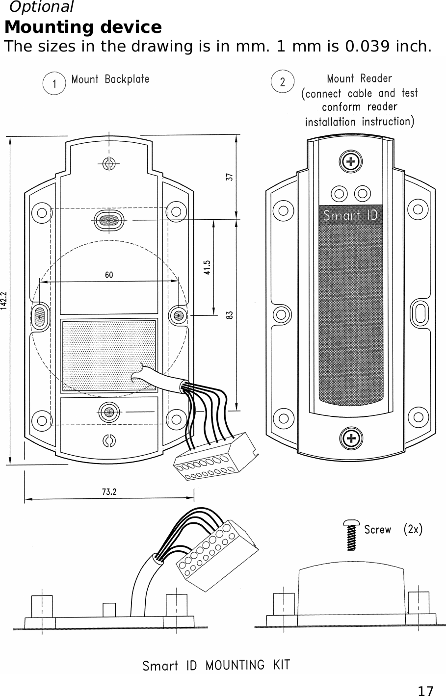
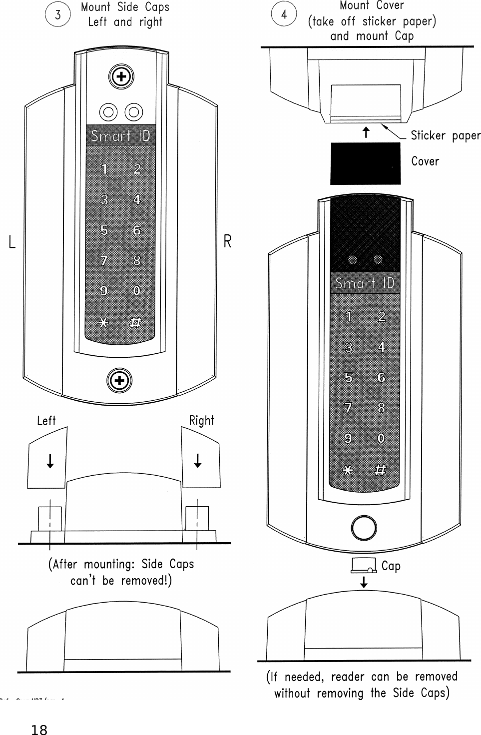
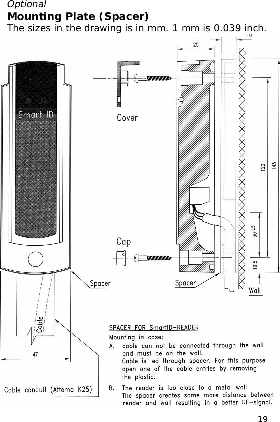
User Manual
2.
user manual
User Manual
Navigation menu
Upload a User Manual
Namespaces
Wiki Guide
HTML
PDF
Info
Views
User Manual
Discussion / Help
Navigation