Integrated Engineering SMARTPIN-1 Security/Remote Control Transmitter User Manual
Integrated Engineering BV Security/Remote Control Transmitter
Contents
- 1. User Manual
- 2. user manual
User Manual
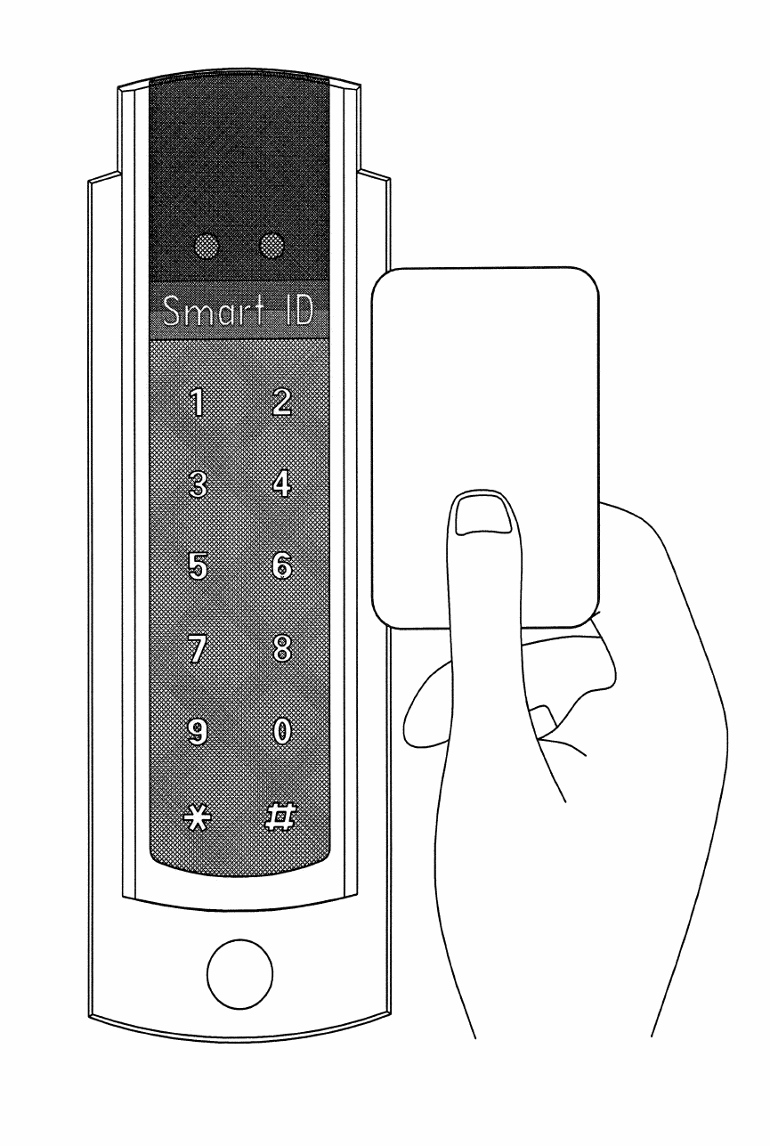
Proximity Card Reader SmartID
Ref. V1-102005 rev oct 2005
2
This manual is applicable for the following SmartID
products:
Partnumber
• 800-8000 SmartID/EM4102
• 800-8001 SmartID/EM4102/pin
• 800-8015 SmartID/Hitag1&2
• 800-8016 SmartID/Hitag1&2/RW
• 800-8025 Mifare Serial number Reader/Rs232
• 800-8030 ISO14443-3 Mifare Sector reader
• 800-8045 ISO14443-3 Mifare Sector reader+ pinpad
• 800-8060 ISO14443-4 DESFire&Mifare rdr (PIV II)
• 800-8075 ISO14443-4DESFire&MifarePINrdr (PIV II)
Extra options for these readers, which are included in
this manual, are:
• 500-0300 Reader Tamper switch
• 500-9287 SmartID/Mountingplate/Grey (Spacer)
• 500-8090 SmartID/SPMD (Switch Box Mounting
Device)

3
Approval
If used according to the instructions, this radio system
meets the basic requirements of article 3 and the
remaining applicable conditions of the R&TTE directive
(1999/5/E6) of March 1999.
4
Table of content:
Features.............................................................5
Indications.........................................................6
Connections.......................................................6
Interface Coding......... Error! Bookmark not defined.
Security..............................................................7
Specifications.....................................................8
Typical read range with an ISO Card......................8
Power Supply......................................................8
Current requirements...........................................8
Interface.............................................................8
Dimensions.........................................................8
Material..............................................................8
Operating temperature.........................................8
Certifications.......................................................9
Cable Distance.....................................................9
SIA recommended cable type for Wiegand signals..10
Cable................................................................10
Wiegand Signal Levels........................................10
Wiegand/Clock&Data ABA reads evaluation...........10
Timing..............................................................11
Installation instruction....................................12
Mullion Mounting (Drawing) ..............................14
Connector Assignments....................................15
Tamper Switch (Drawing) ..................................16
Mounting device (Drawing)................................17
Mounting Plate (Spacer) (Drawing) ...................19
5
Features
The Smart ID Reader has a slim door style mountable
design to match any decor. The buried LED’s and
buzzer allow the Smart ID Readers to be mounted
indoors and outdoors.
The Smart ID Reader accepts 4 to 16 Volts DC. The
output formats like clock-and-data magstripe (ABA /
ISO7811), Wiegand and a number of other formats are
determined by the personalization of the card or
configuration of the reader. The 5 Volt DC capability
allows the replacement of older reader systems
without rewiring or pulling new cables. The Smart ID
Reader offers high reliability, consistent read
characteristics and low power consumption.
Within the Smart ID Proximity Reader Family also
models with a RS232/RS422/RS485 interface are
available for read-only and read/write operations.
The Smart ID Reader Family supports both the 125KHz
and 13.56MHz technologies. Different models are
available for EM4002, EM4050, HiTAG1 and 2, Mifare,
DESFire and I·Code technology. Standard capabilities
include Host system controlled red and green LED’s
and a buzzer.
The Smart ID Reader can be mounted on any surface
without relevant performance degradation. For
mounting on a metal wall a spacer is advised.
Our commitment is to bring non-propriety, open Radio
Frequent Identification (RFID) systems to the market
demonstrated with the Smart ID Reader Family.
6
Mullion mounting
The Smart ID Readers can be mounted on a door
mullion.
Optional there is a mounting kit available in case the
small Smart ID reader will be mounted over a wall box
(mounting US back box, vertical 84 milimeter (3.31
inch), mounting European back box, horizontal 60
millimeter (2.36 inch)).
Indications
When a proximity card is decoded successfully the with
the card associated code is send to the Host system
and the buzzer sounds a short 3KHz beep. Both LED’s
and the buzzer are also controllable by the Host
system.
Connections
The Smart ID Reader Family has a flexible and reliable
connector interface. The space for the cable and the
connector within the Smart ID housing can be sealed
with silicone to withstand harsh environmental
conditions.
Output protocols
The Smart ID Reader Family can operate with any
facility, system or card coding scheme. The output
format, contents and length are determined by the
personalization of the card or configuration of the
reader. Output formats like magstripe, Wiegand and
several others are available.
7
Security
Depending on the model and the RF technology used
the Smart ID Reader Family offers high security
challenge response schemes to protect the RFID air
interface against various attacks schemes like record &
playback attacks.
8
Specifications
Typical read range with an ISO Card
EM4102 up to 7.5 cm (2.95 inch)
Hitag1&2 up to 8 cm (3.15 inch)
ISO14443 up to 3 cm (1.8 inch)
ISO15693 up to 15 cm (5.91 inch)
DESFire up to 2 cm (0.79 inch)
Power Supply
4 – 16 Volt DC
Current requirements
Average 248 mA
Peak 337 mA
Interface
Inputs EMC Prot. 10K ohm pull-ups
Outputs EMC Prot. open drain 0.5 A/max
Dimensions
142 x 46.2 x 25 mm (0.559 x 0.181 x 0.098 inch)
Material
SB housing with polyurethan potting
Operating temperature
-20° to 60° C (-4 to 140 Fahrenheit)
9
Certifications
EN50022, CE, FCC
FCC IDs:
• ISO14443: SmartID/ISO14443/SNR/RS232
PX007Z/MFSNR/RS232 > P4E-SMARTPIN-1
• ISO14443-3: SmartID/ISO14443/Sect
Classic/ISO14443/Sect > P4E-SMARTPIN-1
• DesFire: SmartID/DesFire
Classic/DesFire > P4E-SMARTPIN-1
Consult your National Authority if any
authorization is needed for this product.
This device complies with Part 15 of the FCC Rules.
Operation is subject to the following two conditions:
1) that this device does not cause harmful
interference, and
2) that this device must accept any interference
received, including interference that may cause
undesired operation.
Cable Distance
Up to 150 meter (492 foot), depending on output
protocol and cable type. Recommended cable type:
stranded conductor with overall stranded shield or
equivalent

10
SIA recommended cable type for Wiegand signals
Cable Length Cable Diameter
inch Diameter
mm
Up to 61m (200.1 ft) AWG22 0.025 0.64
Up to 91m (301.8 ft) AWG20 0.03 0.82
Up to 153m (502 ft) AWG18 0.04 1.02
Recommended cable for clock and data ABA track 2
emulation: Up to 25 meter (82 foot), AWG22.
Wiegand Signal Levels
Voh = Output Voltage idle high
Vol = Output Voltage active low
Wiegand/Clock&Data ABA reads evaluation
The SmartID readers provide true open collector
(clean) output C.
Pull-up resistors
External pull-up resistors are required when the
controller does not provide internal pull-up resistance.
Typical pull-up resistor value is 1kOhm.
The pull-up resistor #4 connects from reader
connector pin 3 to a 5 Volt reference.
The pull-up resistor #2 connects from reader
connector pin 4 to a 5 Volt reference.
11
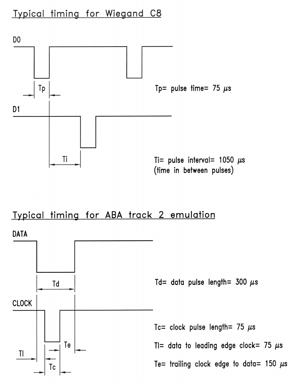
Timing
12
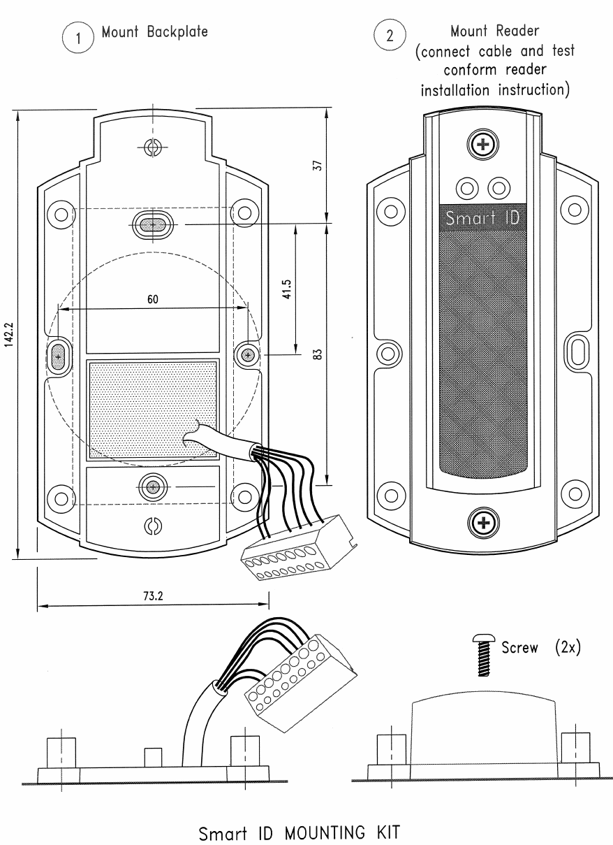
Installation instruction
1) Determine an appropriate position for the Reader
and drill two holes for mounting the reader to the
surface (see mullion mounting drawing on page
12). Do not mount the readers less than 20 cm
(7.87 inch) from each other. Make sure that
enough room to connect the cable is allowed.
Protect the cable against sharp edges and any
damage from chaffing.
2) Remove the Terminal Connector 8 pins from the
back of the Reader. Use a small flat head
screwdriver to loosen off all of the terminals. The
end of the cable should be prepared by cutting it
back to expose the wires and each end should be
twisted to eliminate any loose or frayed wires.
3) The wires should then be connected to the Reader
inline with the Connector Assignments. Wire ends
outside the shielding and optional permanent LED
links should be kept as short as possible.
Note: wires at the connector must be as kept as
short as possible: long, unshielded connections
will reduce the sensitivity of the reader. Twist the
power and ground wires together to avoid creating
magnetic fields.
4) After wiring the reader and the Host system the
Reader is ready to be tested. Apply power and
present a Card to the Reader. The green LED
should flash and the buzzer should beep indicating
a read. If the Host system is connected to the red
and green LED inputs these should follow the
functionality of the Host system.
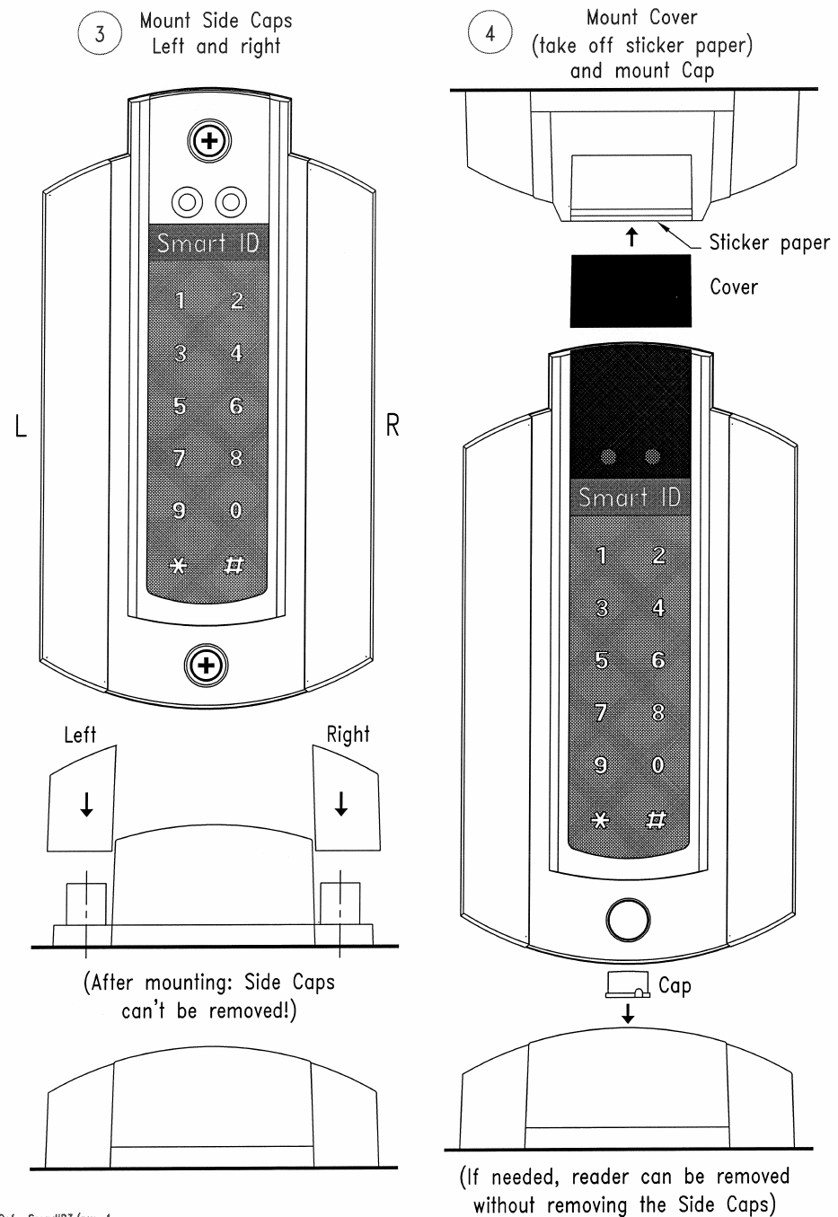
13
5) The Reader should now be secured to the surface
using the appropriate screws. Mount the black
cover (sticker) and mount the cap over the
mounting hole.
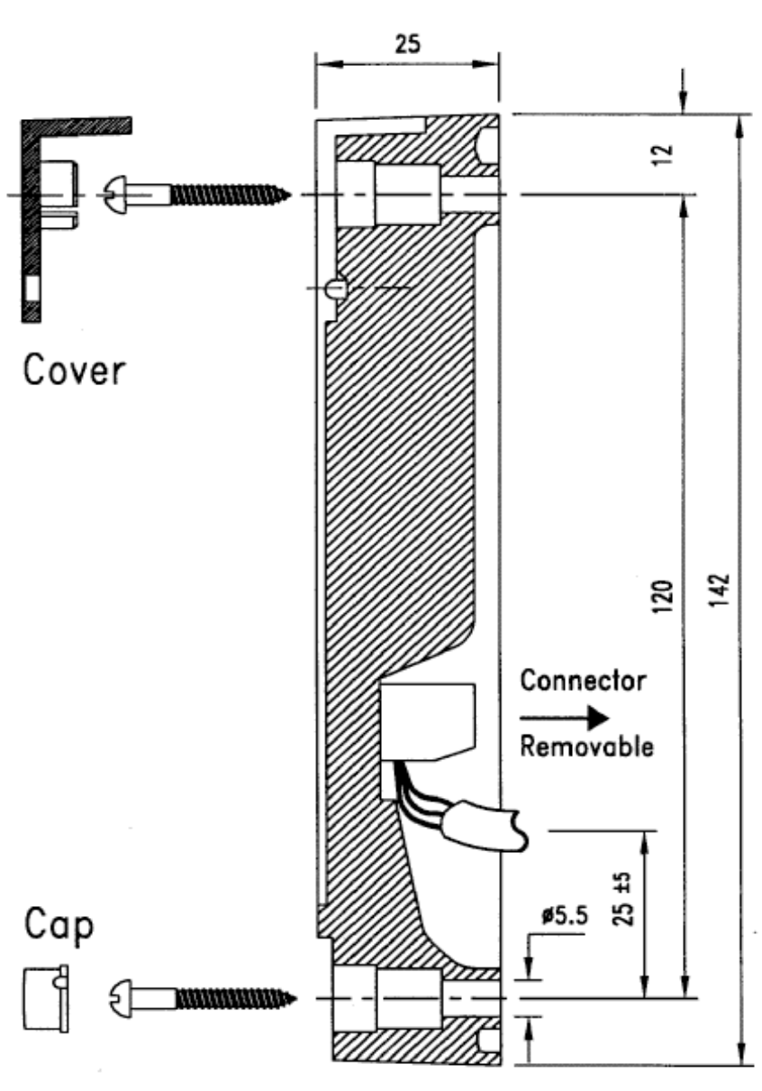
14
Mullion Mounting
The size in the drawing is in mm. 1 mm is 0.039 inch.

15
Connector Assignments
Clock/Data
(ABA) Wiegand RS232 RS422
1
Green LED
input
Green LED
input
Green LED
input)**
Green LED
input)**
2
Led LED
input
Led LED
input
Led LED
input)**
Led LED
input)**
3
Data
D1
Do not
connect
TXA
4
Clock
D0
TXD
TXA
5
Buzzer
input Buzzer
input Do not
connect
RXA
6
Do not
Connect
Do not
Connect RXD
RXB
7
Ground
Ground
Ground
Ground
8
Power
4.75 to
15.00 VDC
Power
4.75 to
15.00 VDC
Power
4.75 to
15.00 VDC
Power
4.75 to
15.00 VDC
Attention: 4 Volt DC is MINIMUM VOLTAGE AT
READER CONNECTOR PINS
)** LED input only valid in read-only application
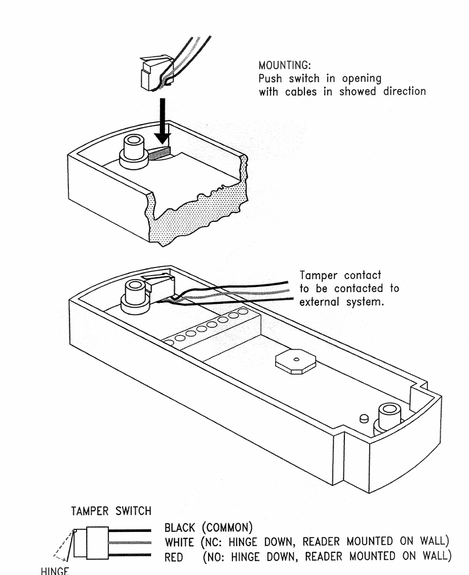
16
Optional
Tamper Switch
17
Optional
Mounting device
The sizes in the drawing is in mm. 1 mm is 0.039 inch.
18
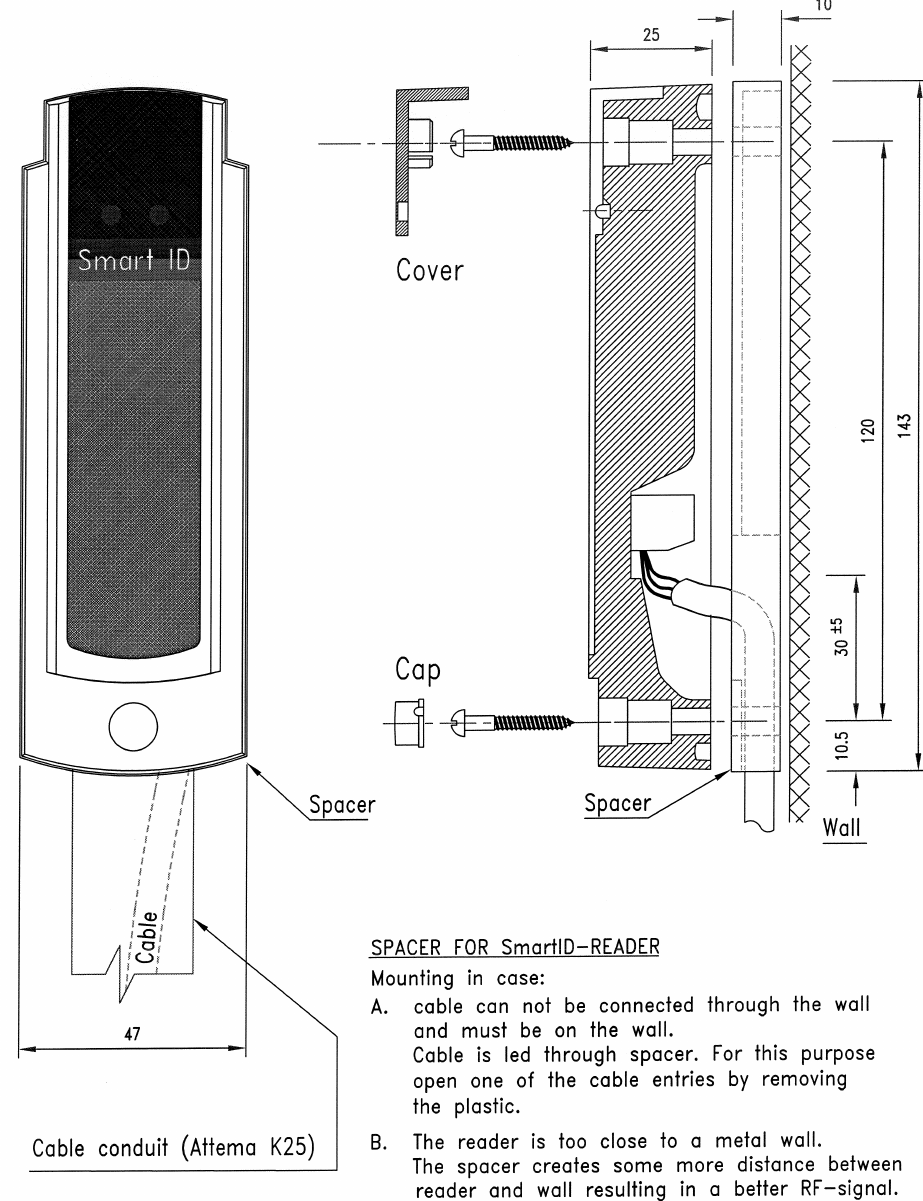
19
Optional
Mounting Plate (Spacer)
The sizes in the drawing is in mm. 1 mm is 0.039 inch.
20
Notes
21
© Copyright 2005
Issue: October 2005 – This manual supercedes and
renders invalid all earlier versions. The information in this
manual can be changed without prior notice.
The information in this manual has been put together to
the best of the authors’ knowledge and conscience. The
manufacturers accepts no liability for the accuracy or
completeness of the information in this manual. In
particular, the manufacturer cannot be held liable for
consequential damages caused as a result of incorrect or
incomplete information. As it is impossible to avoid
mistakes despite all our efforts, we are always grateful if
these are pointed out.
The installation recommendations contained in this manual
assume the most favorable framework conditions. The
manufacturer cannot guarantee that the system will
function perfectly under other conditions.
The manufacturer cannot guarantee that the information
contained in this document is not protected by external
property rights. The manufacturer is not granting licenses
to its own or external patents or other property right.

22