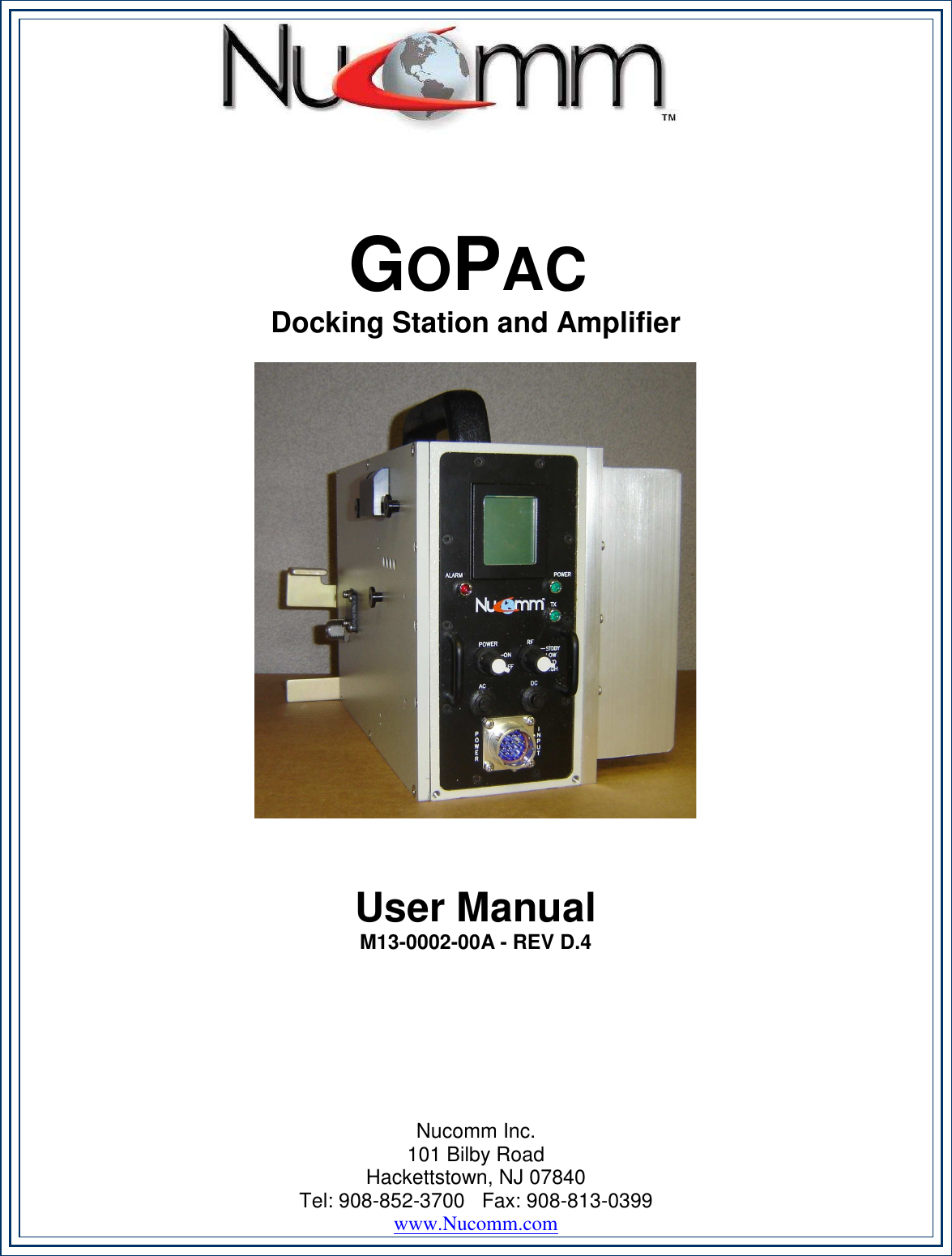
Integrated Microwave Technologies 23GP2-L5 Video Booster Amplifier User Manual M13 0002 00A GoPac revDp4 MANUAL
Integrated Microwave Technologies, LLC. Video Booster Amplifier M13 0002 00A GoPac revDp4 MANUAL
Contents
- 1. Users Manual 1
- 2. Users Manual 2
- 3. Users Manual 3
- 4. Users Manual 4
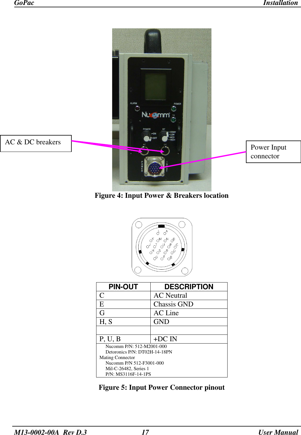
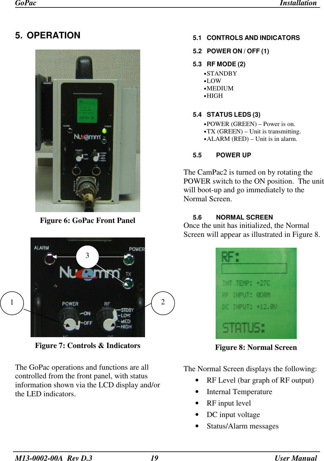
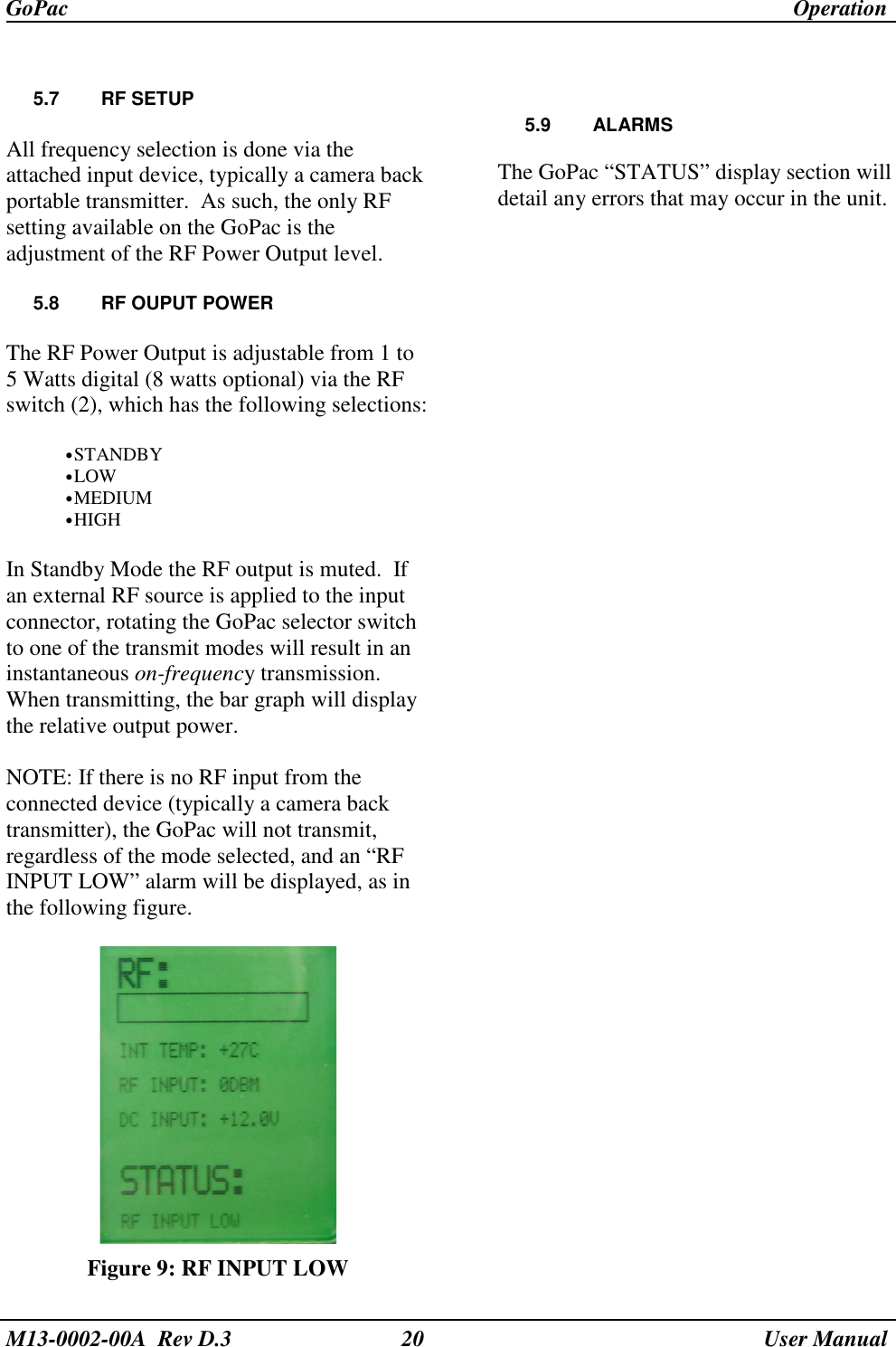
Users Manual 4