Integrated Microwave Technologies 23VT2-P10 MICROWAVE TRANSMITTER User Manual
Integrated Microwave Technologies, LLC. MICROWAVE TRANSMITTER Users Manual
UserManual.wiki
>
Integrated Microwave Technologies
>
23VT2 P10 User Manual
Users Manual
Navigation menu
Upload a User Manual
Namespaces
Wiki Guide
HTML
PDF
Info
Views
User Manual
Discussion / Help
Navigation

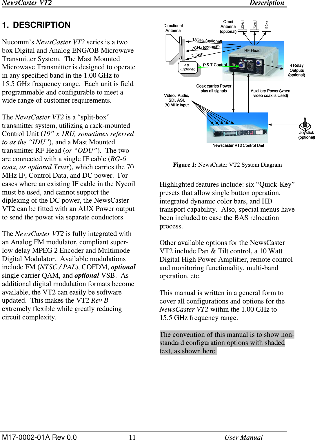
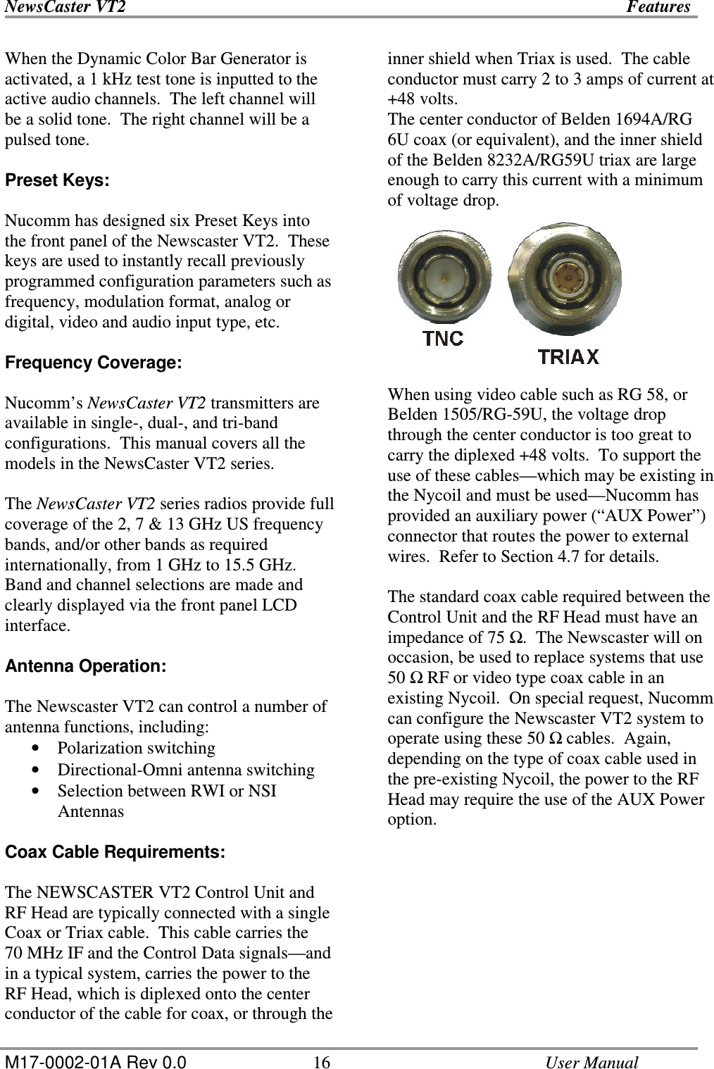
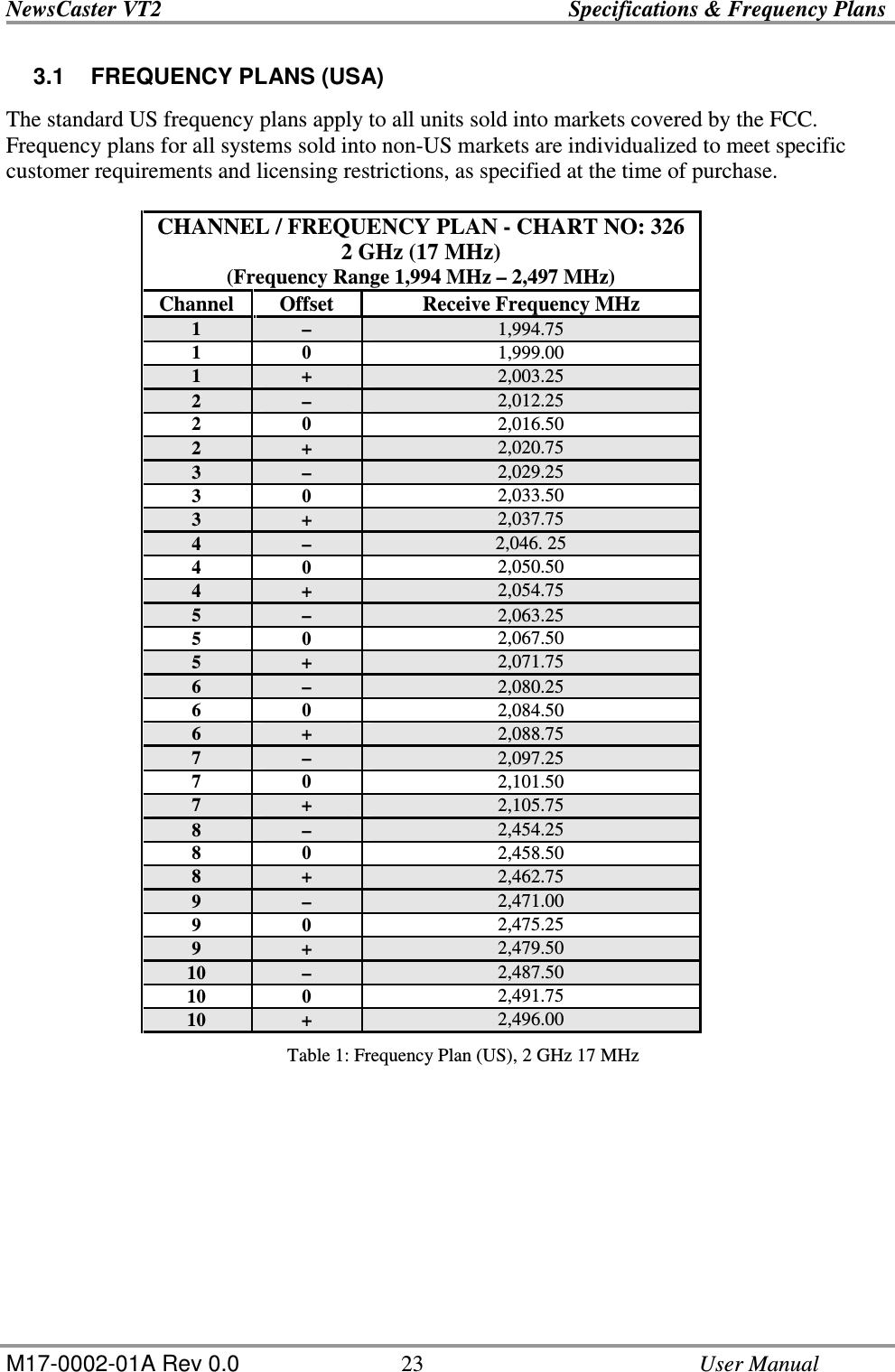
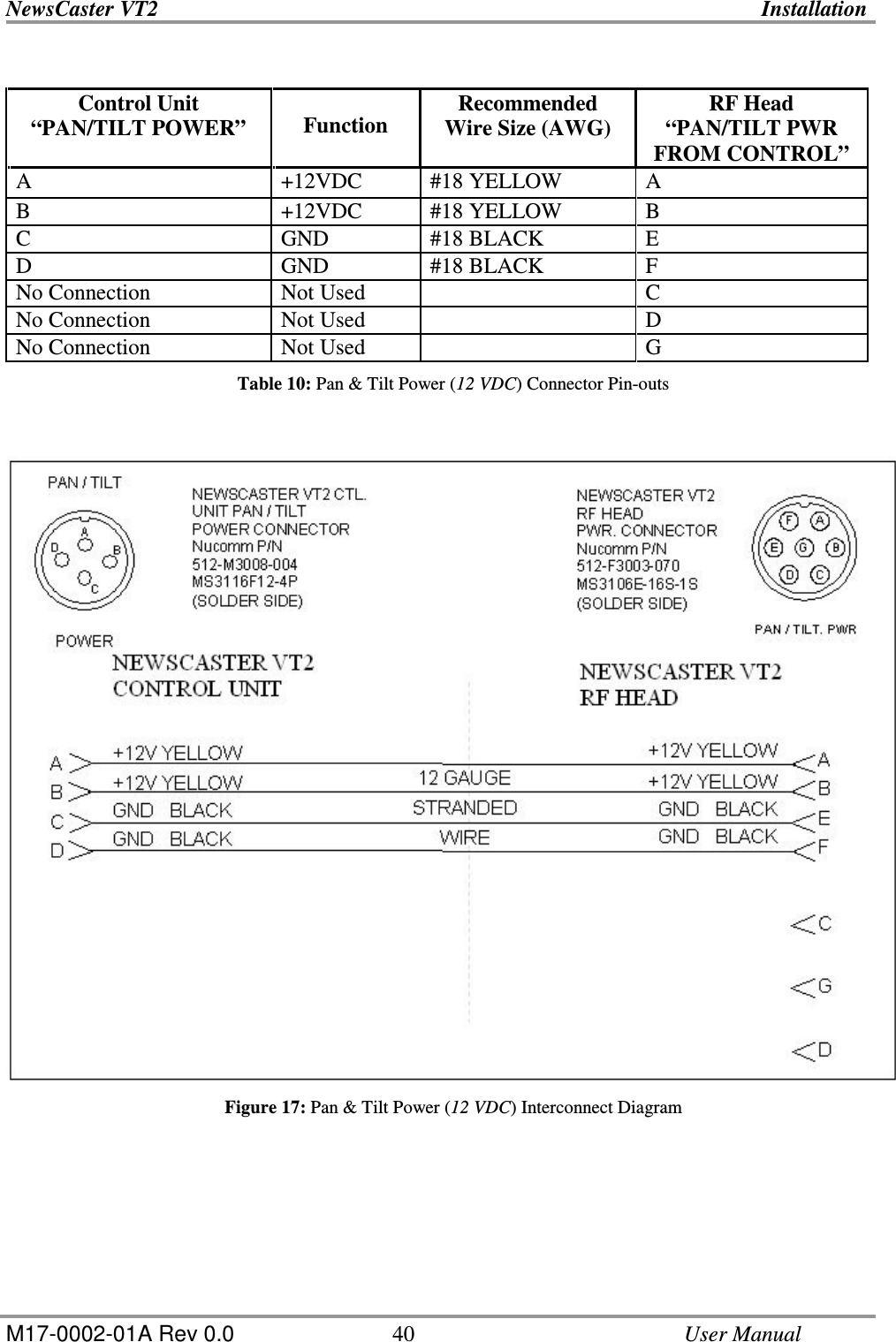
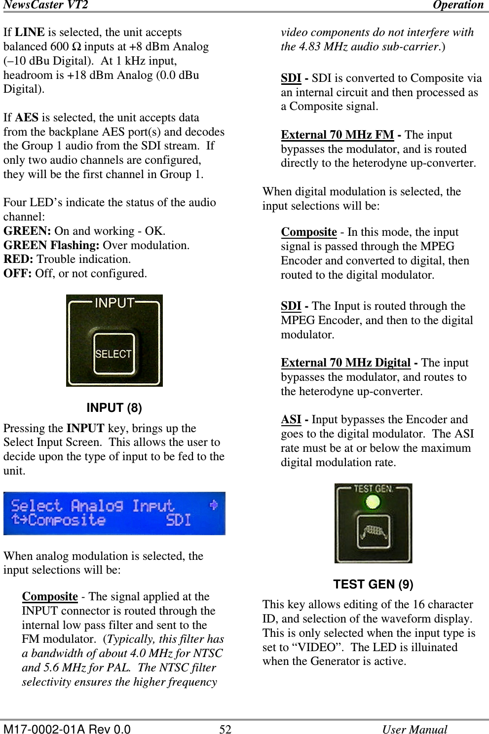
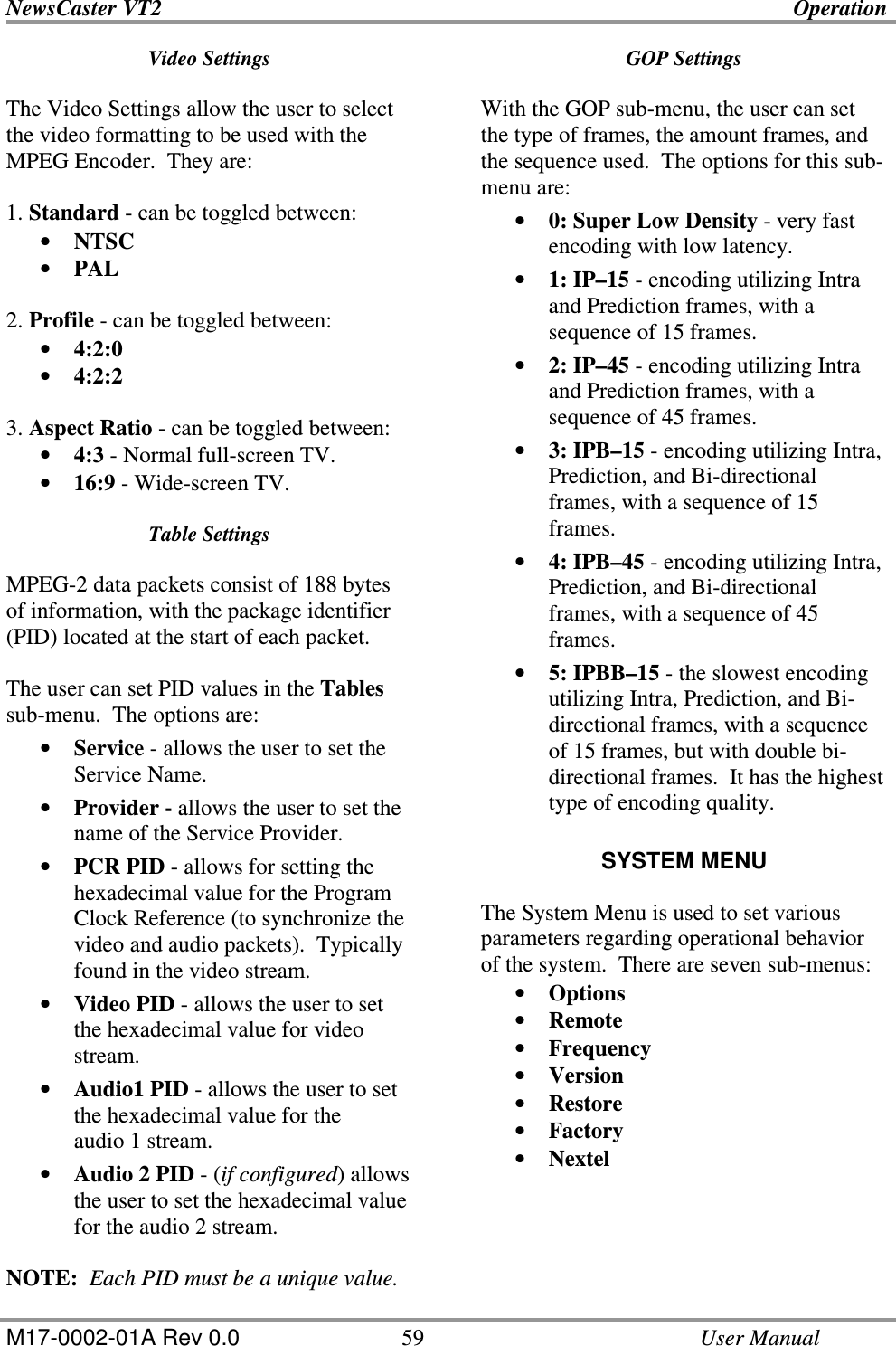
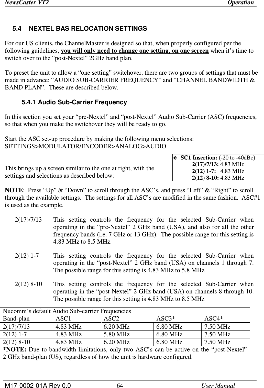
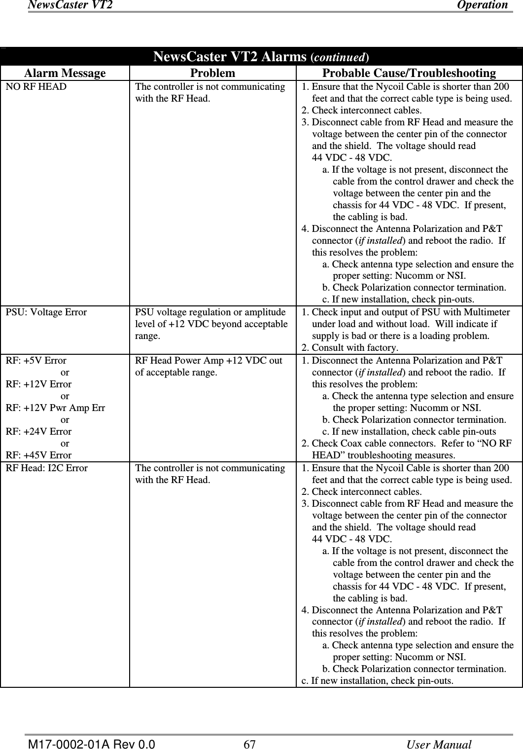
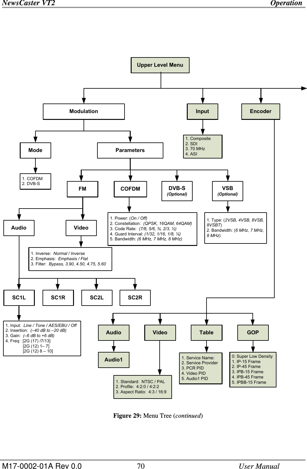
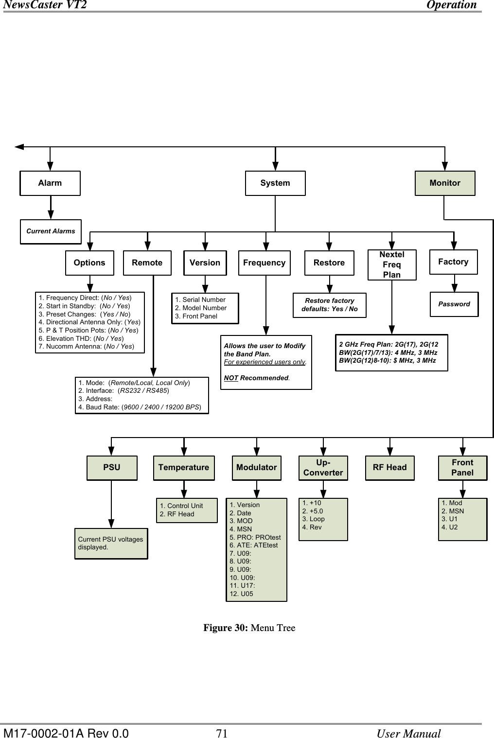
![NewsCaster VT2 Operation M17-0002-01A Rev 0.0 54 User Manual INPUT MENU The Input Menu is used only to set the type of signal that is to be inputted to the unit. • Composite • SDI • 70 MHz • ASI MODULATION MENU The Modulation Menu allows the user to change any of the associated analog or digital parameters. The Modulation Menu is broken down into two sections: Mode and Parameters. (Refer to Figure 7.) Mode Mode allows the user to select the Digital Mode of Operation (COFDM, DVB-S, and VSB). Parameters The Parameters Sub-menu has Analog (FM) parameters and Digital (COFDM, DVB-S, and VSB) parameters. FM PARAMETERS The FM (analog) parameters are divided into two sections: Audio and Video. FM Audio Settings Under the FM Audio sub-menu, there are four channels to choose from. They are: • SC1L (Audio 1 Left) • SC1R (Audio 1 Right) • SC2L (Audio 2 Left) • SC2R (Audio 2 Right) Each has an identical set of parameters. 1. Input - selects the type of audio input source going to the VT2 (Line [analog source], Tone [self-generated source], AES/EBU [digital source], and Off. 2. Insertion - adjusts the input audio level from –40 dB to –20 dB. 3. Gain - adjusts the audio output level from –6 dB to +6 dB. 4. Freq - allows the user to select the FM Audio Channel sub-carrier bandwidth. FM Video Settings Under the FM Video sub-menu, the operator may change three parameter settings. These are: 1. Inverse - which can set the video waveform to Normal (in-phase) or Inverted (180° out-of-phase). 2. Emphasis - allows the operator to switch between Video Emphasis Mode or Video Flat Mode. (In Video Emphasis Mode, the lower video frequencies are rolled-off, while high frequencies are amplified.) 3. Filter - sets the bandwidth of the video filter. This is used to ensure that the audio sub-carriers do not cause interference with video signal when required. The choices are: Bypass (filter off) or bandwidths of 3.9 MHz, 4.5 MHz, 4.75 MHz, or 5.6 MHz.](https://usermanual.wiki/Integrated-Microwave-Technologies/23VT2-P10/User-Guide-1091626-Page-54.png)
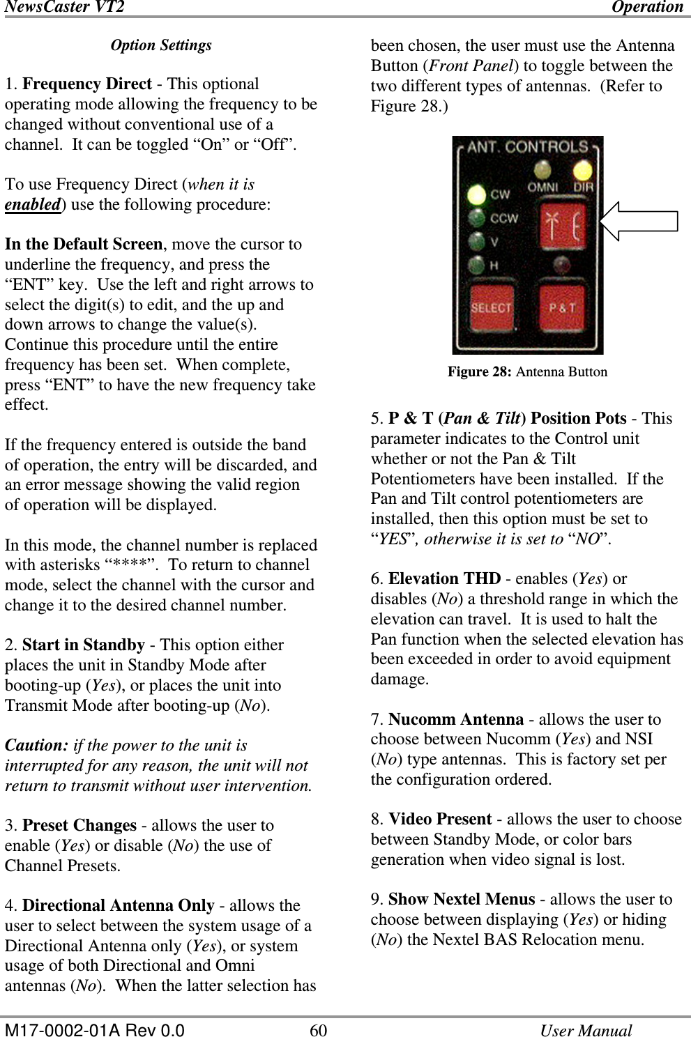
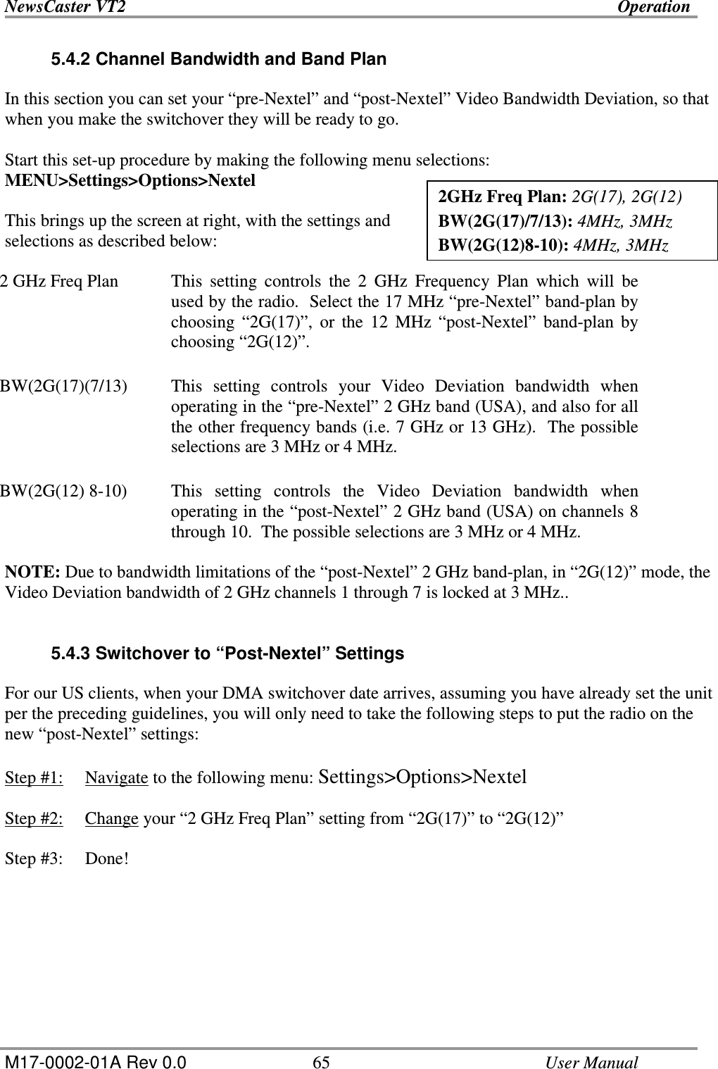
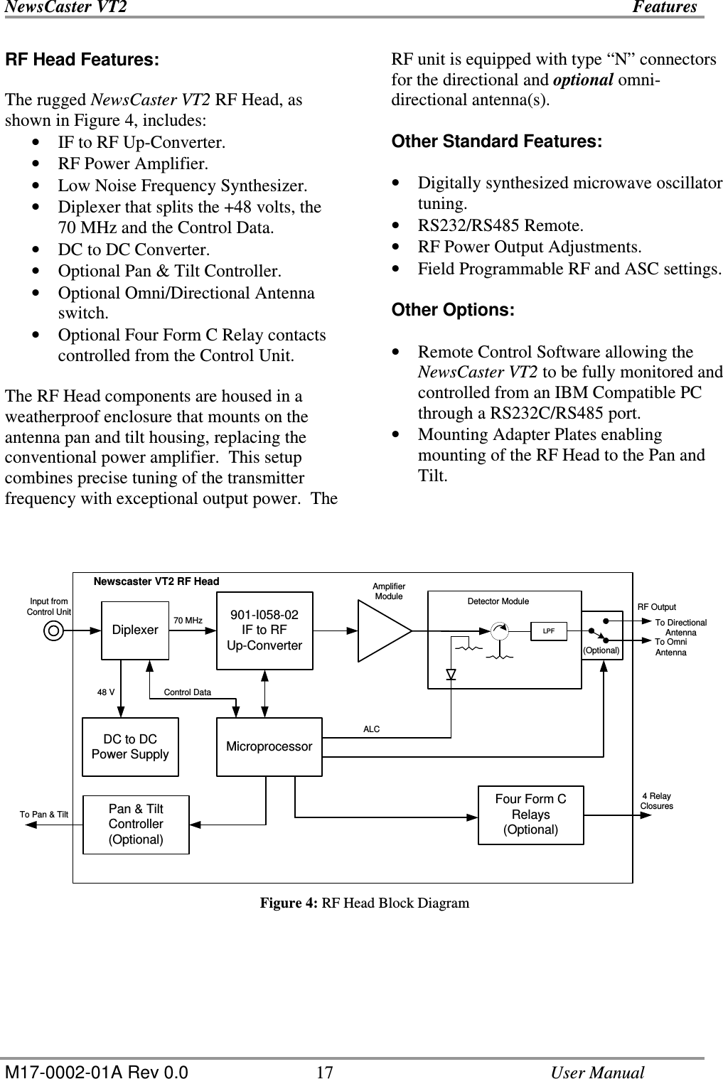
![NewsCaster VT2 Operation M17-0002-01A Rev 0.0 58 User Manual VSB PARAMETERS 1. Type - provides several different methods of modulating the signal for transmission: • 2VSB • 4VSB • 8VSB • 8VSB-T 2. Bandwidth - The bandwidth is the span or width of a carrier frequency. Under the Bandwidth sub-menu, the user can select the size of the carrier bandwidth. The options for this sub-menu are: • 6 MHz • 7 MHz • 8 MHz BW = 6 MHz Data Rate (Mbit/s) 2 VSB 9.7 VSB 4/8T VSB 19.4 8 VSB 29.1 BW = 7 MHz Data Rate (Mbit/s) 2 VSB 11.3 VSB 4/8T VSB 22.6 8 VSB 33.9 BW = 8 MHz Data Rate (Mbit/s) 2 VSB 12.9 VSB 4/8T VSB 25.5 8 VSB 38.8 Table 17: VSB Data Rates Note: the data rate for non-Trellis coded 4 VSB is the same as 8 VSB with Trellis coding (8T VSB). 8T VSB @ 6MHz is the ATSC standard. ENCODER MENU The Encoder Menu allows the user to adjust the MPEG Encoder’s operating parameters. The menu accesses four sub-menus. They are: • Audio • Video • Table • GOP Audio Settings The Audio Settings allow the user to select the audio scheme to be used with the MPEG Encoder. After entering the Audio Menu, select either Audio 1 or Audio 2 (if configured for two digital audios). After selecting the audio channel, there are four parameters that can be set: 1. Input - (Line [analog source], Tone [self-generated source], AES/EBU [digital source], and Off. 2. Sample Rate - the rate is set at 48 kHz and is not changeable. 3. (Input) Level (L) - sets the left-channel audio input level to the encoder from –6 dB to +6 dB. 4. (Input) Level (R) - sets the right-channel audio input level to the encoder from –6 dB to +6 dB.](https://usermanual.wiki/Integrated-Microwave-Technologies/23VT2-P10/User-Guide-1091626-Page-58.png)