Integrated Microwave Technologies 25VST-AMP Very Small Transmitter 25VST-AMP User Manual
Integrated Microwave Technologies, LLC. Very Small Transmitter 25VST-AMP
UserManual.wiki
>
Integrated Microwave Technologies
>
25VST AMP User Manual
User Manual
Navigation menu
Upload a User Manual
Namespaces
Wiki Guide
HTML
PDF
Info
Views
User Manual
Discussion / Help
Navigation
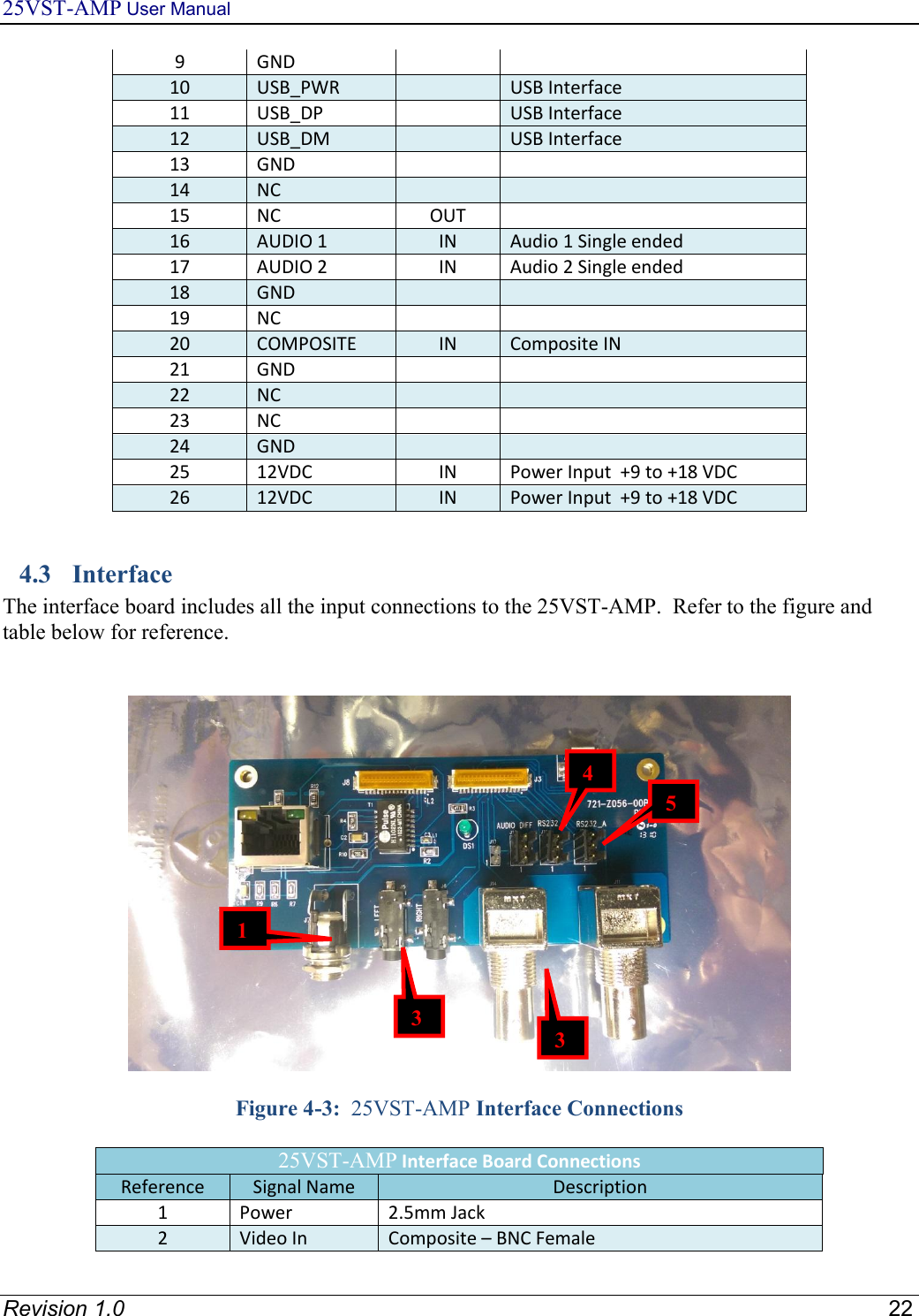
![25VST-AMP User Manual Revision 1.0 21 4.2 Identifying 25VST-AMP Physical Features and Interfaces 4.2.1 COFDM Transmitter AScrew Holes for Mounting DRibbon Cable B25VST-AMP Top Surface EAntenna Port CRibbon Cable Connector; Arrow points to Pin 1. (26 pins total) Figure 4-2: 25VST-AMP – COFDM Transmitter Table 4-1: OEM Model Ribbon Connector Pin Out VST - Multi-pin Connector [Hirose P/N FH33-26s-0.5sh(10)] Pin Number Signal Name Direction Description 1 GND 2 NC 3 NC 4 NC 5 RS232 RX UD IN RS232 User data 6 RS232 TX UD OUT RS232 User data 7 RS232 RX_RC IN RS232 Remote Control 8 RS232 TX_RC OUT RS232 Remote Control](https://usermanual.wiki/Integrated-Microwave-Technologies/25VST-AMP/User-Guide-2813363-Page-21.png)