Integrated Microwave Technologies 25VST-AMP Very Small Transmitter 25VST-AMP User Manual
Integrated Microwave Technologies, LLC. Very Small Transmitter 25VST-AMP
User Manual
25VST-AMP
HD/SD COFDM Transmitter
User Manual
IMT PUBLICATION: M22-25VST-AMP-1A1, REV 1.0

25VST-AMP User Manual
Revision 1.0 2
Revision History
Date Revision Modified By Description
08/31/2015 1.0 SMV Initial release
IMT 25VST-AMP
User Manual
IMT PUBLICATION: M22-25VST-AMP-1A1, REV 1.0
IMT, LLC.
200 International Drive
Mt. Olive, NJ, 07828, USA.
T +1 908 852 3700 F +1 908 813 0399
www.imt-solutions.com
© Copyrighted 2011 - IMT, LLC - Mount Olive, New Jersey 07828

25VST-AMP User Manual
Revision 1.0 3
Contents
1 Introduction ....................................................................................................................................... 8
1.1 Manual Overview ................................................................................................................................. 8
2 25VST-AMP Description ................................................................................................................. 10
2.1 25VST-AMP Features and Benefits ................................................................................................. 10
2.2 25VST-AMP Theory of Operation ................................................................................................... 11
2.2.1 25VST-AMP Block Diagram ............................................................................................................... 11
2.2.2 Interface Board ..................................................................................................................................... 12
2.2.2.1 Power and Control Interface Connector ................................................................................................ 12
2.2.2.2 Audio and Video Input Connectors ....................................................................................................... 12
2.2.3 COFDM Transmitter ............................................................................................................................ 12
2.2.3.1 MPEG4 Encoder ................................................................................................................................... 12
2.2.3.2 Encryption ............................................................................................................................................. 12
2.2.3.3 COFDM Modulator .............................................................................................................................. 12
2.2.3.4 Transmitter Amplifier ........................................................................................................................... 13
2.2.4 Power Distribution ............................................................................................................................... 13
2.2.5 Booster Amplifier ................................................................................................................................. 13
2.2.6 Remote Control via Serial Interface ..................................................................................................... 13
2.2.7 Firmware updates ................................................................................................................................. 13
3 Specifications ................................................................................................................................... 16
3.1 Frequency Bands ............................................................................................................................... 16
3.2 Modulation Modes ............................................................................................................................. 16
3.3 MPEG Encoder .................................................................................................................................. 16
3.3.1 Video .................................................................................................................................................... 16
3.3.2 Audio .................................................................................................................................................... 17
3.4 System ................................................................................................................................................. 17
3.5 Power Requirements.......................................................................................................................... 17
3.6 Environmental .................................................................................................................................... 18
4 Installation ....................................................................................................................................... 20
4.1 Overview ............................................................................................................................................. 20
4.2 Identifying 25VST-AMP Physical Features and Interfaces ........................................................... 21
4.2.1 COFDM Transmitter ............................................................................................................................ 21
4.3 Interface .............................................................................................................................................. 22
4.4 Physical Installation ........................................................................................................................... 23
4.5 Amplifier Installation ........................................................................................................................ 23
4.6 Application Limitations ..................................................................................................................... 24
4.6.1 Shielding Integrity ................................................................................................................................ 24
4.6.2 RF Power Measurement ....................................................................................................................... 24
4.6.3 FCC RF Exposure Requirements ......................................................................................................... 24
4.6.4 Labeling Visibility ................................................................................................................................ 25
4.6.5 Other Cautions ...................................................................................................................................... 25
5 Operation .......................................................................................................................................... 27

25VST-AMP User Manual
Revision 1.0 4
5.1 Power Up the 25VST-AMP ............................................................................................................... 27
5.2 Pre-Configure the 25VST-AMP user options .................................................................................. 27
5.3 User Interfaces ................................................................................................................................... 28
5.4 Using the 25VST-AMP to Transmit Audio and Video Signals ...................................................... 28
5.4.1 Select User Level Settings .................................................................................................................... 28
5.4.2 Transmit Mode ..................................................................................................................................... 28
5.4.3 Verify Operation .................................................................................................................................. 29
5.5 Using the 25VST-AMP To Transmit User Data ............................................................................. 29
5.6 User Interface/NanoController .......................................................................................................... 29
5.7 Using alternate/custom controllers ................................................................................................... 29
5.7.1 Serial Interface Rate, Parity, and Stop Bit Specifications .................................................................... 29
5.7.2 Command and Response Packet Formats ............................................................................................. 29
5.8 Troubleshooting ................................................................................................................................. 30
5.9 Maintenance Information ................................................................................................................. 30

25VST-AMP User Manual
Revision 1.0 5
Figures
Figure 2-1: 25VST-AMP Block Diagram _______________________________________________ 11
Figure 2-2 - Encryption Circuit _______________________________________________________ 12
Figure 2-3: Booster Amplifier Configuration ____________________________________________ 14
Figure 2-4: Input/Interface Board for Booster Amplifier___________________________________ 14
Figure 4-1: 25VST-AMP Application With Optional Host Processor _________________________ 20
Figure 4-2: 25VST-AMP – COFDM Transmitter ________________________________________ 21
Figure 4-3: 25VST-AMP Interface Connections _________________________________________ 22
Figure 4-4: Booster Amplifier Connectios ______________________________________________ 24
Tables
Table 2-1: 25VST-AMP - Summary of High Level Features and Benefits ______________________ 10
Table 2-2: Booster Amplifier Interfaces ________________________________________________ 14
Table 4-1: OEM Model Ribbon Connector Pin Out _______________________________________ 21
Table 5-1: Table of Troubleshooting Tips _______________________________________________ 30

25VST-AMP User Manual
Revision 1.0 6
FCC ID: I4U-25VST-AMP
This device complies with Part 2 and Part 90 of the Federal Communications Commission (FCC)
Rules.
CAUTION:
Changes or modifications to this unit not expressly approved by the party responsible for
compliance could void the user’s authority to operate this equipment.

25VST-AMP User Manual
Revision 1.0 7

25VST-AMP User Manual
Revision 1.0 8
1 Introduction
This document is a user manual for IMT’s 25VST-AMP microwave video transmitter with high power
amplifier. The 25VST-AMP is a compact transmitter with high power amplifier that digitally encodes
video signals and transmits them using COFDM modulation over microwave frequencies using secure
methods. The unit accepts composite video inputs in NTSC or PAL format. It has a built in MPEG4
(H.264) encoder and COFDM modulator. The 25VST-AMP is housed on an easy to install plate.
Throughout this manual, the product is referred to as the “25VST-AMP,”or simply the “transmitter.”
1.1 Manual Overview
The contents of this manual are as follows:
Chapter 2 – Describes the theory of operation and the features of the 25VST-
AMP.
Chapter 3 – Contains a list of the 25VST-AMP specifications. The specifications
include transmitter feature specifications, power requirements,
environmental specifications, and I/O specifications.
Chapter 4 – Explains how to install the 25VST-AMP.
Chapter 5 – Describes operating procedures for the 25VST-AMP. It also contains
an overview of the 25VST-AMP programmable serial interface.
A preface at the front of this manual contains Warranty and Repair information.
The rear of this manual contains warranty and repair information.
25VST-AMP User Manual
Revision 1.0 9

25VST-AMP User Manual
Revision 1.0 10
2 25VST-AMP Description
This chapter describes the 25VST-AMP transmitter theory of operation, features, and benefits. It also
contains a block diagram of the 25VST-AMP transmitter circuitry.
The 25VST-AMP features an interface board for all input connections. Audio, video and power are
input to the 25VST-AMP via the interface board. A programmable user interface is also accessed via a
serial port on the interface. This can be used to pre-configure the 25VST-AMP settings and to check
the status of the settings.
The 25VST-AMP internal circuitry compresses the audio and video signals, organizes the compressed
data into digital video transport streams, and optionally encrypts the data. The transmitter uses
COFDM modulation and transmits at microwave frequencies in the band supported by the unit. The
signal level out of the base transmitter is calibrated for ideal power into the final amplifier. The High
Power Amplifier linearly amplifies the COFDM signal and outputs via a SMA-Female type connector.
Though the unit ships pre-configured, a graphical user interface that runs on a PC is available to
modify the operating parameters. Optionally, custom software written to implement the RS232
command set may be used. Refer to Chapter 5, “Operation” for more information.
IMT has the ability, should the need ever arise, to provide the user with firmware files and instructions
for local firmware installation, such as for feature upgrades, etc.
2.1 25VST-AMP Features and Benefits
Table 2-1: 25VST-AMP - Summary of High Level Features and Benefits
Feature Benefit
COFDM Microwave Digital Video Transmitter
MPEG 4 COFDM Transmitter
Frequency Agile Transmitter User programmable channels and offsets within
frequency ranges.
Accepts NTSC or PAL Composite Video
Inputs
Compatible with industry standard video
camera outputs.
Optional Stereo Analog Audio Inputs Direct audio input option for use with video
signals that do not contain audio.
MPEG4 (H.264) Encoder Industry standard video compression.
Implements latest algorithms including B
frames.
High Power Output The integrated amplifier offers range extension
25VST-AMP User Manual
Revision 1.0 11
Remote Control GUI for Programming the
25VST-AMP
Convenient menu and button based graphical
user interface for Windows PC’s.
GUI uses 25VST-AMP RS-232 remote control
serial port.
Can be used to program the preset settings on
the top panel.
2.2 25VST-AMP Theory of Operation
2.2.1 25VST-AMP Block Diagram
Figure 2-1: 25VST-AMP Block Diagram
Major blocks in the 25VST-AMP include:
Interface
o NTSC Composite Video Input Interface
o Stereo/Mono Audio Input Interface
o Programmers Serial Interface for Remote Control Purposes
o Internal Microprocessor and Memory
25VST-AMP User Manual
Revision 1.0 12
o USB Interface for Firmware Updates
o Power Circuitry
COFDM Transmitter
o MPEG4 Video Compression Circuit
o Data Encryption Circuit
o COFDM Modulator
o Microwave Transmission Amplifier
Power Distribution
High Power Amplifier
2.2.2 Interface Board
2.2.2.1 Power and Control Interface Connector
The 25VST-AMP Power and Control Interface includes power and ground connections plus two RS-
232 serial port interfaces. One of the RS-232 interfaces can be connected to a laptop or other PC to
program the transmitter configuration. The second RS-232 interface can be used to transmit user data
through the transmitter along with the audio and video streams.
2.2.2.2 Audio and Video Input Connectors
This 25VST-AMP model has two analog audio inputs that can be used for stereo audio and one NTSC
or PAL composite video input. Refer to Chapter 3 for specifications of these signals.
2.2.3 COFDM Transmitter
2.2.3.1 MPEG4 Encoder
The 25VST-AMP compresses the input video signal before modulation and transmission to reduce
bandwidth. The 25VST-AMP contains a built-in MPEG4 (H.264) compliant encoder for this purpose.
The 25VST-AMP features the latest compression methods utilizing B frames for more accurate
encoding of compressed video signals.
2.2.3.2 Encryption
The transmitter supports BCRYPT1 and BCRYPT2. BCRYPT2 is very similar to BCRYPT1 with
improvements made to support re-multiplexing. Both encryption modes support AES 128 and AES256
key lengths.
Figure 2-2 - Encryption Circuit
2.2.3.3 COFDM Modulator
The COFDM modulator receives data from the output of the MPEG4 encoder through a circuit that
enhances the security of transmissions.

25VST-AMP User Manual
Revision 1.0 13
The 25VST-AMP is able to transmit data at high data rates and with low error rates using COFDM
modulation techniques. The data rate used by the transmitter depends upon the CODFM modulator
settings used.
2.2.3.4 Transmitter Amplifier
The 25VST-AMP microwave transmitter circuits mix the signal to the desired microwave frequency.
The signal is filtered and boosted through a low noise output amplifier.
The 25VST-AMP has a single SMA-Female type connector. The output impedance is 50 ohms.
2.2.4 Power Distribution
Distributes power to components.
2.2.5 Booster Amplifier
The 25VST-AMP features a 5 Watt booster amplifier. The booster amplifier may be packaged as a
stand-alone amplifier for user installation or as part of an integrated product.
2.2.6 Remote Control via Serial Interface
An RS-232 command set is implemented to allow remote control of all configuration options, as well
as monitoring of internal status and settings. Commands and responses are sent via the RS-232 serial
interface located on the Interface Board.
The IMT NanoController GUI is available for controlling the unit via the RS-232 serial interface. Any
Windows compatible computer running Windows XP or Windows 7 with 500 MB of memory and 1
GHz Pentium or above can be used. Refer to Chapter 5, “Operation” for more information.
Optionally, users can create custom control interfaces as required to suit their applications. The RS-232
command set, or “remote protocol”, is available upon request for this purpose.
2.2.7 Firmware updates
The unit firmware may be updated via the USB interface on the Interface Board, using the IMT
NanoTx Programmer software. .
25VST-AMP User Manual
Revision 1.0 14
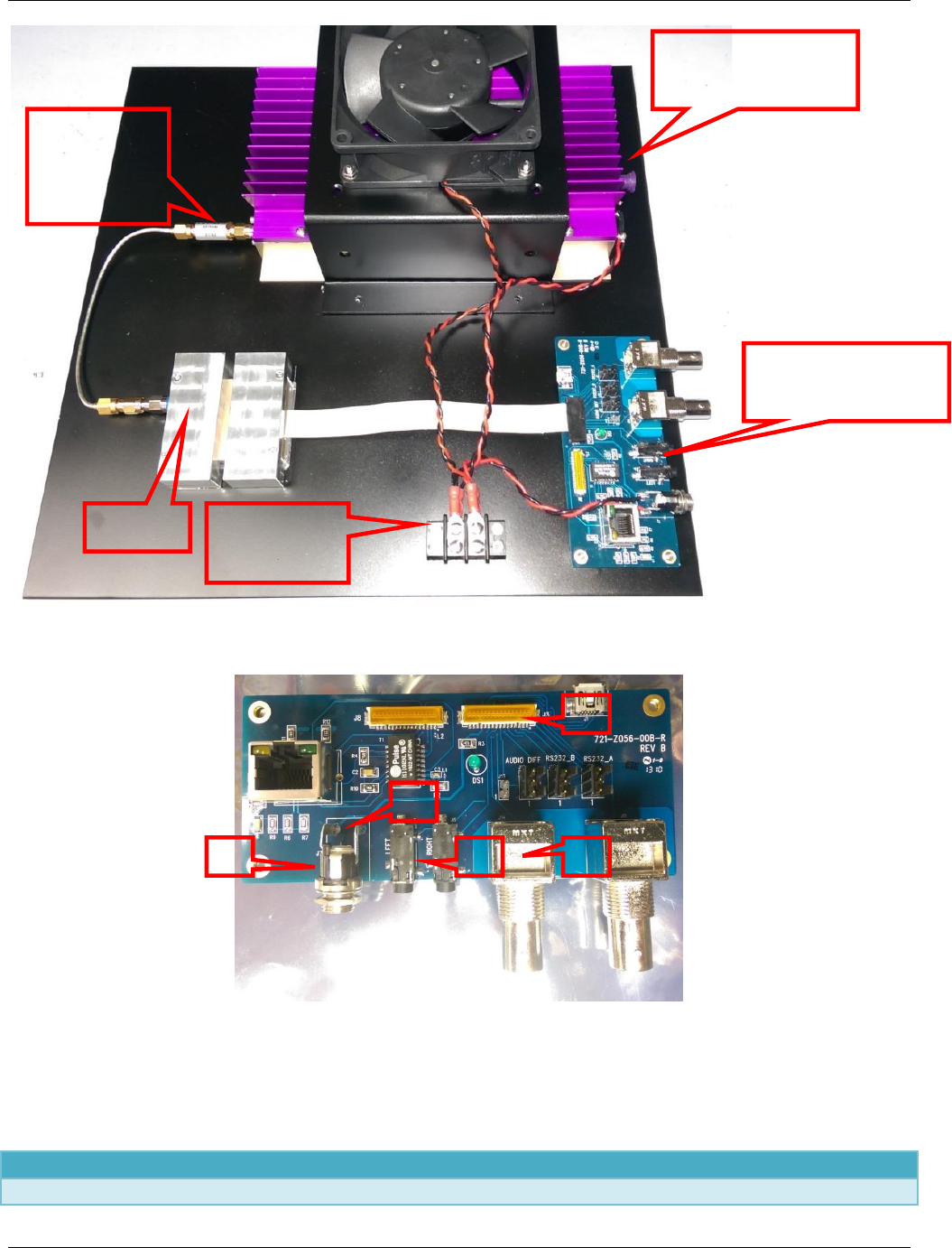
Figure 2-3: Booster Amplifier Configuration
Figure 2-4: Input/Interface Board for Booster Amplifier
Table 2-2: Booster Amplifier Interfaces
Reference Function Connector
1 Power In 2.5mm jack
Amplifier with
Heat Sink
25VST-
AMP
Power
Distribution
RF Cable
with
Attenuator
Input/Interface
Board
1
2
3
4
4

25VST-AMP User Manual
Revision 1.0 15
2 Video In BNC - Female
3 Audio In Left and Right jack
4 Transmitter Interface Ribbon Connector (J3)
5 Power to Distribution Leads with spade lugs
6 RF Output SMA Female

25VST-AMP User Manual
Revision 1.0 16
3 Specifications
3.1 Frequency Bands
Base Part
Number
Frequency
(GHz)
RF
Power
(dBm)
DC
Power
(W)
25VST-13 2.400-2.483 37 <75
Tuning step size: ............................... 250 kHz step size
Frequency stability: .......................... ± 10ppm
Transmit Modes via Remote Control:
Standby: ............................................ No RF output
Normal: ............................................. Instantly on frequency transmission
3.2 Modulation Modes
Modulation 1
Modulation Formats: ........................ COFDM (DVB-T)
Carriers: ............................................ 2K
Constellation: ................................... QPSK, 16QAM
Code Rate: ........................................ 1/2, 2/3, 3/4, 5/6, 7/8
Guard Interval: ................................. 1/32, 1/16, 1/8, 1/4
Bandwidth: ....................................... 6 MHz, 7 MHz, and 8 MHz
Modulation 2 (Optional)
Modulation Formats: ........................ COFDM (Proprietary)
Carriers: ............................................ 2K
Constellation: ..................................... QPSK
Code Rate: ........................................ 1/2, 3/4
Guard Interval: .................................. 1/32
Bandwidth: ........................................ 1.25MHz, 2.5MHz
3.3 MPEG Encoder
Method: .................................................. MPEG-4 Part 10/H.264
3.3.1 Video
Video Coding: .................................... AVC
Video Input: ....................................... Composite
NTSC: ............................................... 720 x 480(4:2:0)
PAL: .................................................. 720 x 576(4:2:0)

25VST-AMP User Manual
Revision 1.0 17
3.3.2 Audio
Audio Coding: ................................. ISO/IEC 11172-3(Layer II)
Audio Sample Rate: ........................... 48Khz
Audio Channels: ............................... 1 Stereo, 2Mono Standard,
Audio Input: ...................................... Line, Gain selectable
........................................................... Mic, Gain selectable
Tone: .................................................. Level Adjustable
3.4 System
Video Present: ......................................... Remote Standby or Test Generator
Test Generator (Dynamic): .................... SMPTE CB(NTSC)/100%
........................................................... CB(PAL)
........................................................... 16 Character ID (Matches SDT Service name).
........................................................... 1KHz Tone/Pulse
Encryption (optional): ............................. AES Block Cypher, supporting key size of 12
................................................................ and 256bit (FIPS PUB 197)
User Data: ............................................... RS232 Side channel, 300-115K Baud
Remote Control: ..................................... Remote RS232
Local Control: ....................................... None
Presets: .................................................. 16 user configurable presets through GUI.
3.5 Power Requirements
Input range: ............................................ DC: +9 to +18
Power consumption: ............................... See table above

25VST-AMP User Manual
Revision 1.0 18
3.6 Environmental
Item Specification
Temperature Range, Operational, Bottom Surface
–10° to +65°C Base plate temperature
Temperature Range, Storage
–40° to +80°C
Humidity
0% to 95% RH, non-condensing
Altitude, Operating
0 to 20,000ft (6,000 m) Maximum
Altitude, Storage
0 to 50,000ft (15,000 m) Maximum

25VST-AMP User Manual
Revision 1.0 19
25VST-AMP User Manual
Revision 1.0 20
4 Installation
This chapter contains steps for installing the 25VST-AMP transmitter in typical environments where it
may be used.
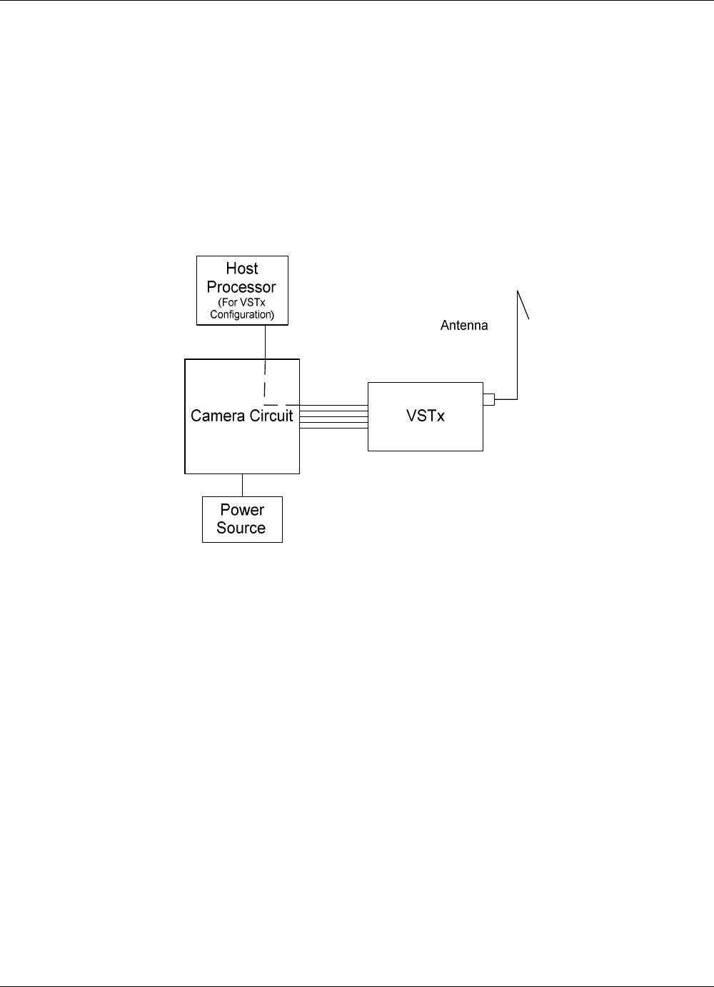
4.1 Overview
The 25VST-AMP is used as an integrated part of a system that typically contains a camera and power
supply. 25VST-AMP applications may also contain a host processor that is used in the field to re-
configure settings in the 25VST-AMP.
Figure 4-1: 25VST-AMP Application With Optional Host Processor
25VST-AMP User Manual
Revision 1.0 21
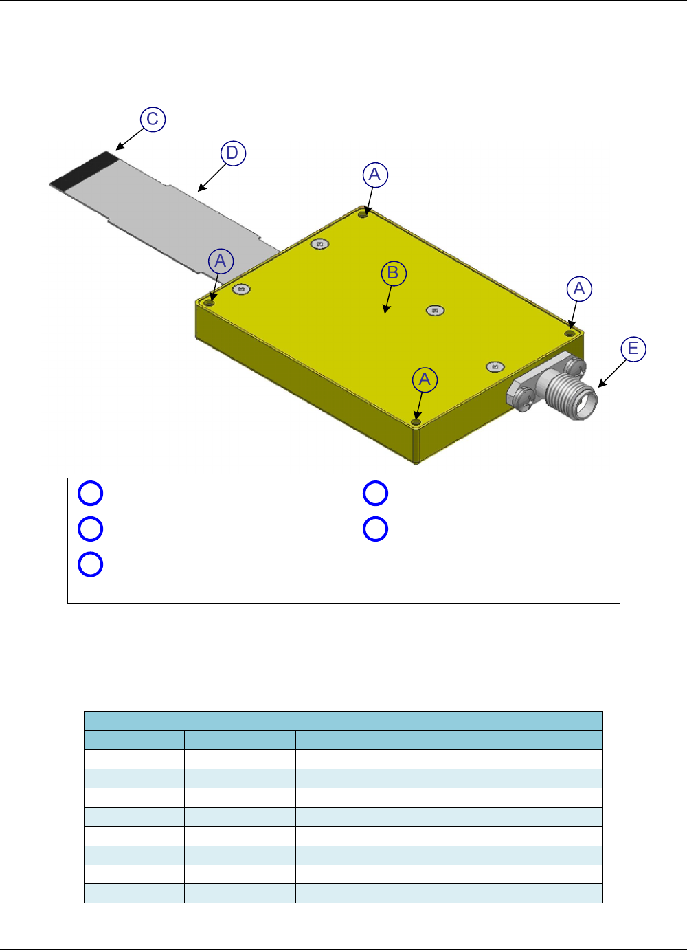
4.2 Identifying 25VST-AMP Physical Features and Interfaces
4.2.1 COFDM Transmitter
AScrew Holes for Mounting DRibbon Cable
B25VST-AMP Top Surface EAntenna Port
CRibbon Cable Connector;
Arrow points to Pin 1. (26 pins total)
Figure 4-2: 25VST-AMP – COFDM Transmitter
Table 4-1: OEM Model Ribbon Connector Pin Out
VST - Multi-pin Connector [Hirose P/N FH33-26s-0.5sh(10)]
Pin Number
Signal Name
Direction
Description
1
GND
2
NC
3
NC
4
NC
5
RS232 RX UD
IN
RS232 User data
6
RS232 TX UD
OUT
RS232 User data
7
RS232 RX_RC
IN
RS232 Remote Control
8
RS232 TX_RC
OUT
RS232 Remote Control
25VST-AMP User Manual
Revision 1.0 22
9
GND
10
USB_PWR
USB Interface
11
USB_DP
USB Interface
12
USB_DM
USB Interface
13
GND
14
NC
15
NC
OUT
16
AUDIO 1
IN
Audio 1 Single ended
17
AUDIO 2
IN
Audio 2 Single ended
18
GND
19
NC
20
COMPOSITE
IN
Composite IN
21
GND
22
NC
23
NC
24
GND
25
12VDC
IN
Power Input +9 to +18 VDC
26
12VDC
IN
Power Input +9 to +18 VDC
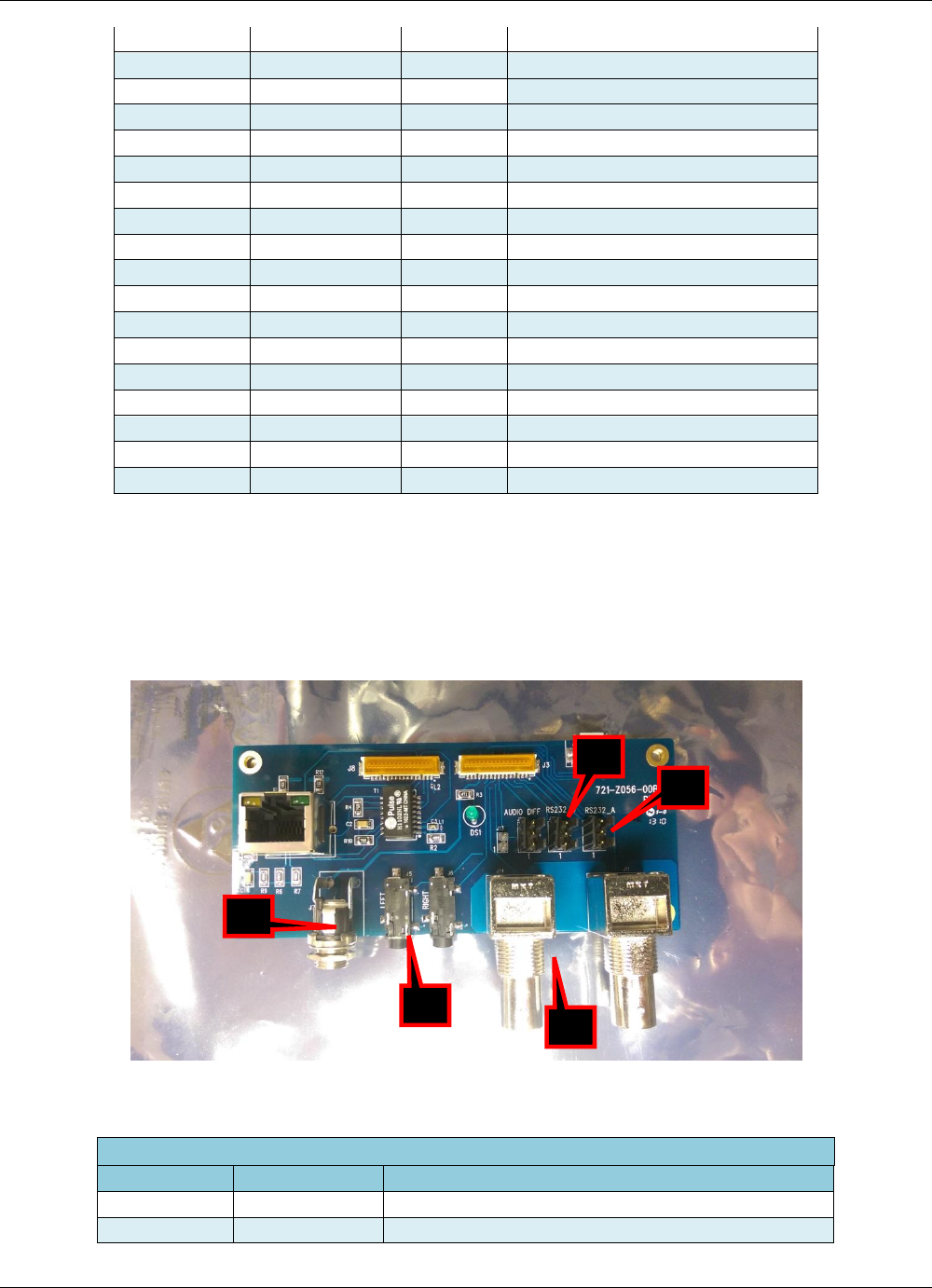
4.3 Interface
The interface board includes all the input connections to the 25VST-AMP. Refer to the figure and
table below for reference.
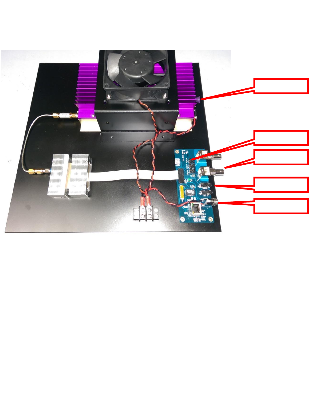
Figure 4-3: 25VST-AMP Interface Connections
25VST-AMP Interface Board Connections
Reference
Signal Name
Description
1
Power
2.5mm Jack
2
Video In
Composite – BNC Female
1
4
3
3
5

25VST-AMP User Manual
Revision 1.0 23
3
Audio
Left and Right - Jack
4
RS232 TX UD
3 Pin Molex
5
RS232 RX_RC
3 Pin Molex RS232 Remote Control
4.4 Physical Installation
The 25VST-AMP is configured via the programmable serial interface. Should you desire to program
the unit while in your application, then your application design must provide a means to connect to the
serial interface. If your application cannot support a means to connect to the serial interface, then you
must pre-configure the unit prior to installation. Refer to Section 5.
The 25VST-AMP requires installation using proper thermal dissipation methods. The unit has an
internal fan and the fan openings must not be blocked.
The unit should not be operated inside another enclosure unless sufficient cooling is provided such that
the case temperature is within the range specified in Chapter 3.
Warning: Before applying power ensure proper antenna and/or termination is on the RF port.
4.5 Amplifier Installation
The Booster amplifier will come pre-installed on a plate with all interface board and connections.
Simply connect 12VDC power supply to power jack, and antenna via RF cable to the RF Output.
25VST-AMP User Manual
Revision 1.0 24
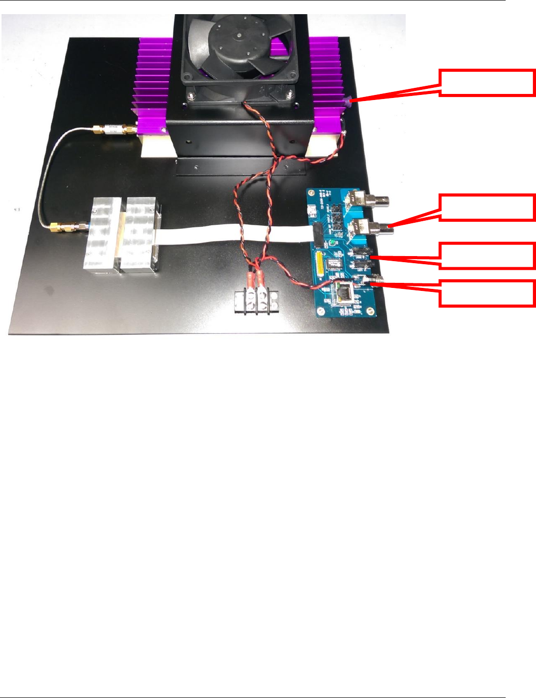
Figure 4-4: Booster Amplifier Connectios
4.6 Application Limitations
4.6.1 Shielding Integrity
When this device is integrated into a user configuration, care shall be taken to maintain Radio Frequency (RF)
shielding integrity. All RF paths shall employ coaxial cable and high-quality RF connectors. Integration
drawings and photographs shall be provided to IMT for review upon request. IMT retains responsibility for the
function of this device as designed and granted. Device integrators assume responsibility for ensuring that the
installed environment is equivalent to the reference design environment, and for maintaining RF performance
integrity as related to integration and installation.
The antenna for this device shall be installed with a separation of not less than 20cm from other antennas in
the installed environment. This recommendation is for system-to-system isolation. More separation might be
necessary, depending on the characteristics of other systems present.
4.6.2 RF Power Measurement
Upon completion of integration, and prior to commencing transmitter operation, an RF output power
measurement shall be made to ensure that the output power does not exceed 5W.
4.6.3 FCC RF Exposure Requirements
This device is intended for application as a mobile radio transmitter, and it produces RF energy when
transmitting. The Federal Communications Commission (FCC) requires that RF Exposure to personnel be
Power Input
Audio Input
Video Input
RF Output

25VST-AMP User Manual
Revision 1.0 25
limited in accordance with their published regulatory standards (47 CFR 1.1307(b), 1.1310, 2.1091, 2.1093).
The recommendations of the American National Standards Institute (ANSI), the Institute of Electrical and
Electronics Engineers, Inc. (IEEE),and the National Council on Radiation Protection and Measurements (NCRP)
were used in the development of the FCC limits for human RF exposure. Additional information regarding the
hazards of RF exposure can be found in the FCC OET Bulletin No. 56.
By FCC definition, a mobile transmitter installation requires a minimum safe separation distance of 20cm
between a transmitting antenna and any person. The 25VST-AMP has been designed to comply with FCC RF
exposure regulations for occupational/controlled-environment conditions at this separation distance when an
antenna with gain not exceeding 2.5dBi is installed. This is the maximum antenna gain that can be used
consistent with the approval granted to this device. Higher gain antennas shall not be used, and users shall
verify that the proper antenna has been installed before commencing transmitter operation. The antenna
used for this transmitter must be installed to provide a separation distance of 20cm from all persons, and must
not transmit simultaneously with any other antenna or transmitter, except in accordance with FCC multi-
transmitter product procedures. In the event that the transmitter is not visible to the user when installed, a
warning label requiring this separation distance shall be placed in a prominent and visible location adjacent to
the transmitting antenna. Please contact IMT to procure additional labels if needed.
As noted above, this device is intended for use only by trained occupational/professional staff and only in a
work-related use condition. Users of this device shall be made fully aware that the transmitter produces RF
energy, and shall be able to exercise control over their exposure to RF energy from this device. RF Exposure
allowable limits are higher in occupational/controlled-environment conditions as a result of the foregoing
conditions. Consequently, the foregoing awareness and control conditions shall be strictly maintained.
4.6.4 Labeling Visibility
As noted above, when this device is installed in a mobile platform, care shall be exercised to maintain visibility
of product identification and warning/caution labels. The FCC-ID label shall be visible either on the installed
product, or when the transmitter location is accessed. Also as noted above, the RF Exposure warning label
shall be visible adjacent to the transmitting antenna, or a duplicate label shall be placed such that it is visible
adjacent to the transmitting antenna. Additional labels can be procured from IMT if needed.
4.6.5 Other Cautions
This device is not approved for use in explosive or combustible environments such as vehicle fueling
or other locations where flammable vapors or particulates might be present. Obey all posted mobile
radio usage limitations.
This device could present a hazard of unexpected activation of explosive apparatus when used in the
vicinity of blasting operations. Obey all posted mobile radio usage limitations in the vicinity of active
blasting areas.
25VST-AMP User Manual
Revision 1.0 26

25VST-AMP User Manual
Revision 1.0 27
5 Operation
While this chapter contains basic information about the operation of the 25VST-AMP transmitter, the
programming of the unit (including preset configuration) via the NanoController GUI is not covered.
Please refer to the “Nano Controller” manual (IMT Publication: M27-0001-00A) for detailed
information on how to program and configure the unit.
In this section you will find info on how to use the transmitter to transmit video, audio, and user data.
At the end of the chapter you will find troubleshooting and maintenance information.
5.1 Power Up the 25VST-AMP
Turn on the power to the overall system.
Note: The 25VST-AMP requires up to 40 seconds to complete its internal power up sequence.
Supply current will jump up in steps as internal circuits are powered. The final DC supply current
will settle after 20 seconds.
5.2 Pre-Configure the 25VST-AMP user options
The 25VST-AMP has a wide range of programmable settings. Before using the 25VST-AMP in your
application, you should pre-configure it to for the settings you want to use in your application.
Settings are selected and configured using the NanoController software, or a third party alternative.
Please refer to the NanoController documentation for details, or contact IMT Technical Support.
25VST-AMP User Manual
Revision 1.0 28
5.3 User Interfaces
The interface board includes all input connections to the 25VST-AMP. Refer to the figure for
reference.
Figure 4 3: 25VST-AMP Interface Connections
5.4 Using the 25VST-AMP to Transmit Audio and Video Signals
The 25VST-AMP uses a COFDM modulation scheme. Receiver systems used with the 25VST-AMP
must be compatible and capable of receiving the type of video transport streams transmitted by the
25VST-AMP. Compatible receivers include the IMT VSRx receivers and certain other IMT products.
Contact IMT for more information.
5.4.1 Select User Level Settings
By use of the available interface(s), make appropriate settings so that your transmitter and suitable
receiver are on the same RF and modulation settings.
5.4.2 Transmit Mode
Via the Remote Control, place the unit in to TX mode. The 25VST-AMP may be set in the configured
presets to automatically turn on in the transmit mode either at all times or when it detects a video
presence.
Power Input
Audio Input
Video Input
RF Output
RS232
Interface

25VST-AMP User Manual
Revision 1.0 29
5.4.3 Verify Operation
Verify unit operation by one of the following methods:
If your system contains a host processor capable of communicating with the unit via the
serial interface, use the NanoController to check the status of the unit.
Detect the transmitted signal using a spectrum analyzer.
Using an appropriate receiver, verify that you are receiving audio and video from your
application setup.
5.5 Using the 25VST-AMP To Transmit User Data
The User Data Interface can be used to packetize user data along with the main audio and video
information. The User Data can be received and output by compatible IMT receivers. The user data
interface must be programmed using the serial interface.
5.6 User Interface/NanoController
The IMT NanoController GUI is used both as the user interface and as the preset configurator. The
NanoController Software is sent with the 25VST-AMP via USB stick. To Install the NanoController
insert the USB stick into your computer and follow the installation instructions. The NanoController
software installs the same way as most Windows applications. Refer to the NanoController manual for
further use instructions
5.7 Using alternate/custom controllers
The implementation of an RS-232 command set, or Remote Protocol, allows the use of customized
interfaces to perform virtually all unit operations, including:
Configure Settings
Query Status
The Remote Protocol consists of command and response messages, or packets. The internal CPU
handles interpretation of the packets to set unit parameters, and provide responses back through the
serial interface.
In addition to IMT’s NanoController, alternate control interfaces may be developed, or available from
third parties. Additionally, commands and responses may be entered and viewed manually using a
command terminal.
The Remote Protocol is available upon request from IMT.
5.7.1 Serial Interface Rate, Parity, and Stop Bit Specifications
Refer to the Remote Protocol for information about the baud rate, number of data bits, stop bits, and
flow control methods.
5.7.2 Command and Response Packet Formats
This section provides a brief introduction to the serial interface command and response packet formats.
The command packets use the following format:

25VST-AMP User Manual
Revision 1.0 30
NU <tt> <ss><##><cc><dd><CS><CR><LF>
Where the fields are ASCII and are defined as follows:
NU
Literal
<tt>
Address of target (0x01 – 0xFF)
<ss>
Address of source (0x00 – 0xFF)
<##>
Packet Length (Packet Length = Command Length + Data Length)
<cc>
Command (0x00-0xFF) – Different values are used for each command.
<dd>
Data (Hex Format) – Data values are encoded with a variety of meanings.
<CS>
(1’s complement of <tt> to end of data)
<CR>
Carriage Return
<LF>
Line Feed
After a command packet is received, the unit returns a response packet. Response packets have the
same basic format as command packets, except that the source and destination are reversed, and the
command field specifies the type of response being sent.
5.8 Troubleshooting
Problem Possible Explanations Actions to Take
No video No Power Check power source
Camera Malfunction Try a different camera
Possible Receiver system issue
Verify that all modulation type
and encryption/decryption
parameters match at transmitter
and receiver.
Video Signal Reception Poor Receiver not properly positioned
Try improved location
25VST-AMP
Programmable
Serial Interface Does Not
Respond
No Power Check power source
Poor connection via ribbon
cable Check connections
Host processor GUI settings
issues
Verify that the host processor
running a GUI interface for
programming the 25VST-AMP
is setup and operating correctly.
Table 5-1: Table of Troubleshooting Tips
5.9 Maintenance Information
Follow these procedures when maintaining the device:

25VST-AMP User Manual
Revision 1.0 31
Dry the device immediately if it comes into contact with water or other liquids. Warranty
does not cover liquid damage.
Do not submerge the device or use it directly in rain.
Use ESD Precautions whenever handling the device
Do not touch electrical connections.
Do not open the device. This voids the warranty.
Keep the device clean by wiping with a soft, dry cloth. If necessary, dampen only using a
solution suitable for cleaning electronic devices. Warranty does not cover cleaning
damage.

25VST-AMP User Manual
Revision 1.0 32
Proprietary Information and Disclaimer Notice
All information and graphic images contained within this manual are the sole property of IMT, LLC,
and are issued in the strictest of confidence. This material may not be reproduced, stored, copied, or
converted in any form, nor shall it be disclosed to others or used for manufacturing or any other
purpose without the written permission of authorized IMT personnel.
IMT has made every effort to ensure the accuracy of this material at the time of printing. However, as the
specifications, equipment, and this manual are subject to change without notice, IMT assumes no responsibility
or liability whatsoever for any errors or inaccuracies that may appear in this manual, or for any decisions based
on its use. This manual is supplied for informational purposes only and should not be construed as a
commitment by IMT.
Warranty
Equipment manufactured by IMT, LLC is warranted to meet all published specifications and to be free
from defects in material and workmanship within a period of two years from date of original shipment.
The company’s liability under this warranty is limited to:
Servicing or adjusting equipment.
Replacement of defective parts.
Any equipment returned to the factory shall have the freight paid for by the buyer.
Equipment showing damage by misuse, abnormal conditions of operation, or attempts to repair by
other than authorized service personnel shall be excluded from this warranty. IMT shall in no event
be responsible for incidental injury or property damage. Since IMT has no control over conditions of
use, no warranty is made or implied as to suitability for the customer’s intended use, beyond such
performance specifications as are made part of the purchase order. There are no warranties
expressed or implied, except as stated herein. This limitation on warranties shall not be modified by
verbal representations.
Shipping Damage
Equipment shipped FOB IMT shall become the property of buyer upon delivery and receipt from carrier. Any
damage in shipment should be handled by the buyer directly with the carrier. Immediately request the carrier’s
inspection upon evidence of damage in shipment.
Field Service
IMT products are designed with easy access to components to facilitate service. However, some modules
cannot be service in the field. To prevent voiding of the warranty, please contact Tech Support before servicing
or making any repairs. The user is cautioned to read all module descriptions in this manual. Warnings are
included in the circuit descriptions and on certain modules themselves.
Replacement Modules
Troubleshooting to the component level is often not cost-effective and frequently impossible. Often the
practical method of effecting repairs is to substitute known good spare modules for suspect units. Replacement
modules for our standard product line are usually available.

25VST-AMP User Manual
Revision 1.0 33
Technical Support Information
Technical Support personnel are available to extend technical assistance to customers while installing,
operating, or troubleshooting IMT equipment. Please have your model number and serial number available.
Telephone
During IMT business hours, 8:30am - 5:30pm EST (-5 Hours, GMT), call:
US ........................................................... 908-852-3700
International ............................................ 001-1-908-852-3700
After hours, call:
US or International .................................. 888-531-3892
Email
Email address ....................................................... service@nucomm.com
Internet
Web address ......................................................... www.imt-solutions.com
Equipment Returns
If equipment cannot be successfully restored through telephone consultation, return to the factory may be
required. Loaner items may be available until the repaired items are returned.
For out-of-warranty equipment only: We evaluate all returned units, and then confers with the client on
corrective action. If no fault is found, or no corrective action is authorized, a diagnostic fee may be charged.
Prior to returning products to the factory, please obtain a return material authorization (RMA) number and
shipping instructions from Tech Support.
When returning equipment, it is very helpful to enclose a note containing the following:
RMA number.
Serial number.
A detailed description of the problem.
Name of an engineer or technician we may contact regarding problems encountered.
A “ship to” and “bill to” address.
Ship all returns to:
IMT, LLC
Attn: RMA# (your RMA number)
200 International Drive
Mt. Olive, NJ, 07828, USA
(908) 852-3700
For International returns:
In addition to the instructions above, when shipping internationally we recommend the use of a courier such as
Federal Express, UPS, etc, and that the goods be shipped DOOR-TO-DOOR PRE-PAID. This will reduce
Customs costs, handling charges and delays. Enclose all the information above, plus a statement that the
equipment was manufactured in the United States (the latter is needed to expedite customs processing).

25VST-AMP User Manual
Revision 1.0 34
IMT, LLC.
200 International Drive
Mt. Olive, NJ, 07828, USA.
T +1 908 852 3700 F +1 908 813 0399
www.imt-solutions.com