Integrated Microwave Technologies 58CP2 5.8GHz CAMPAC2 User Manual
Integrated Microwave Technologies, LLC. 5.8GHz CAMPAC2
UserManual.wiki
>
Integrated Microwave Technologies
>
58CP2 User Manual
User Manual
Navigation menu
Upload a User Manual
Namespaces
Wiki Guide
HTML
PDF
Info
Views
User Manual
Discussion / Help
Navigation
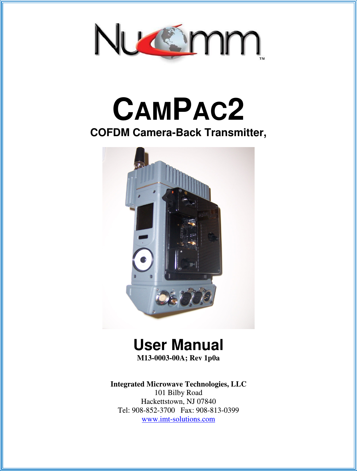
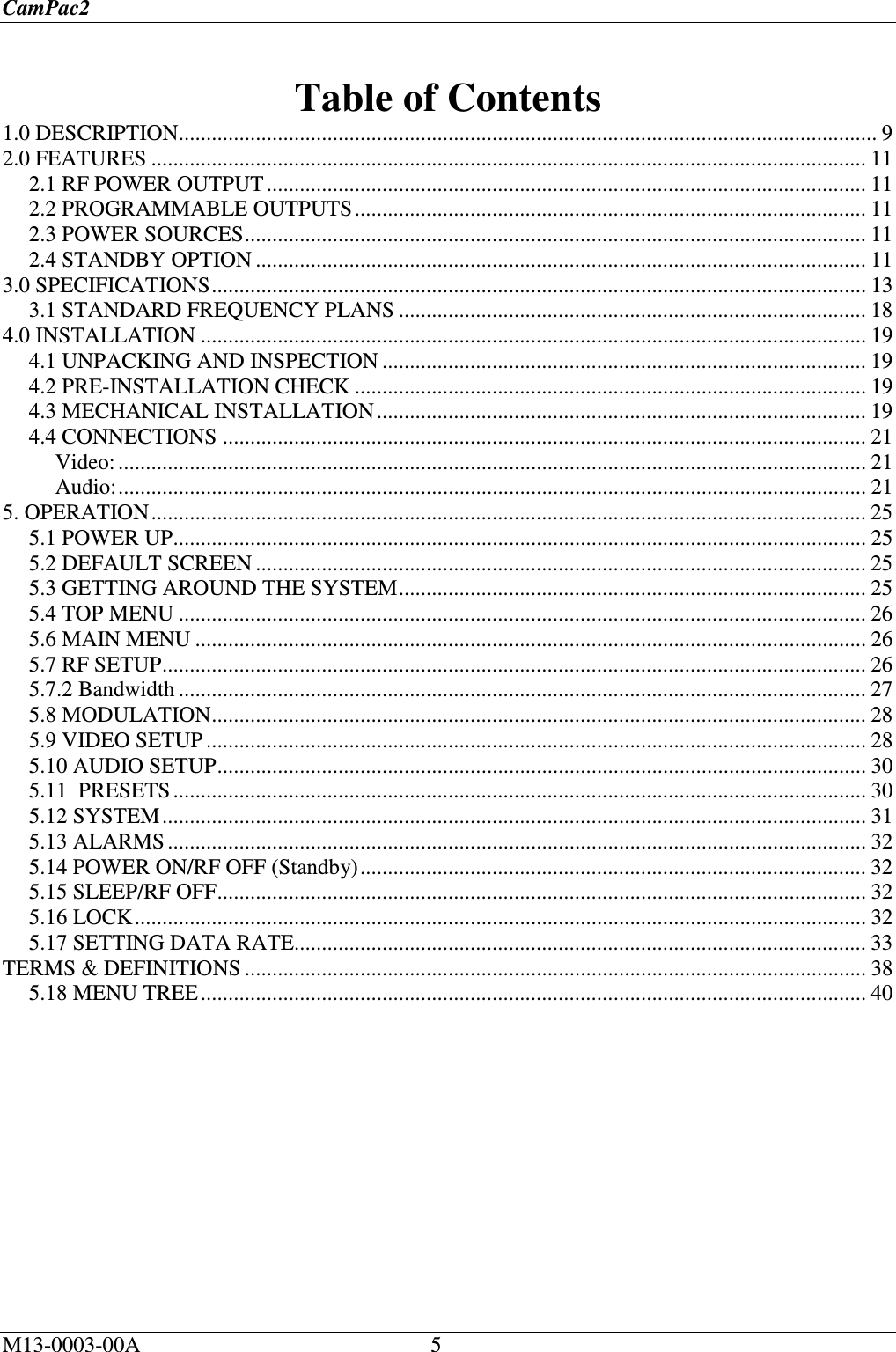

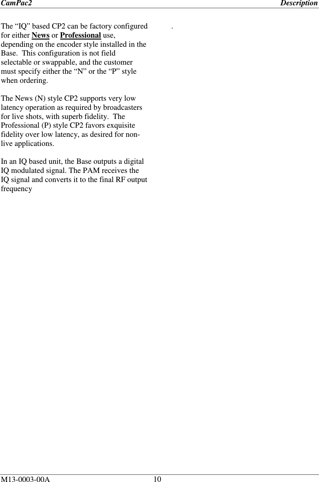

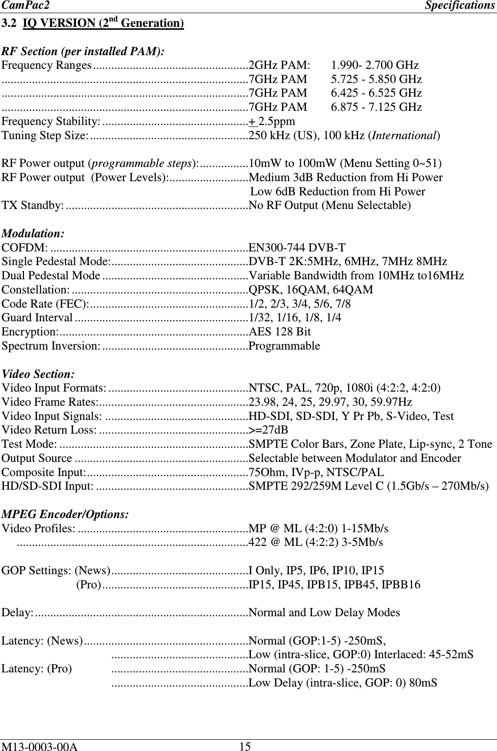
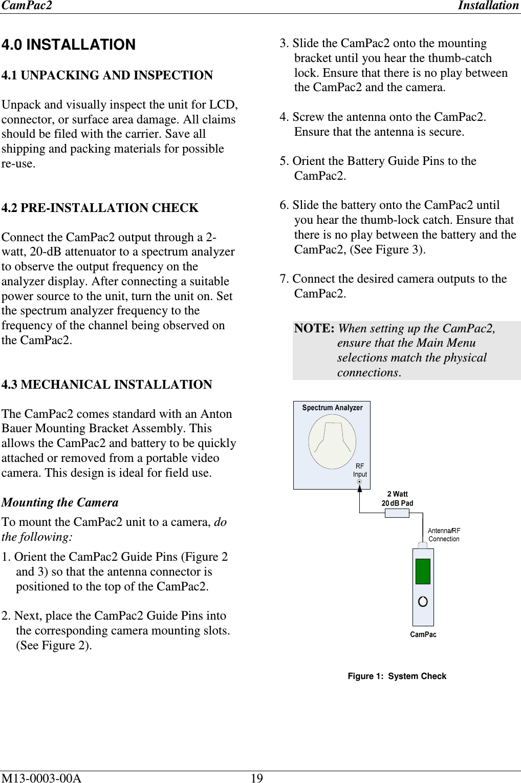
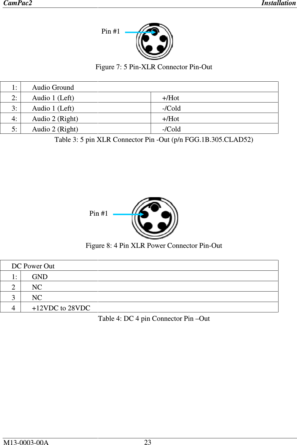

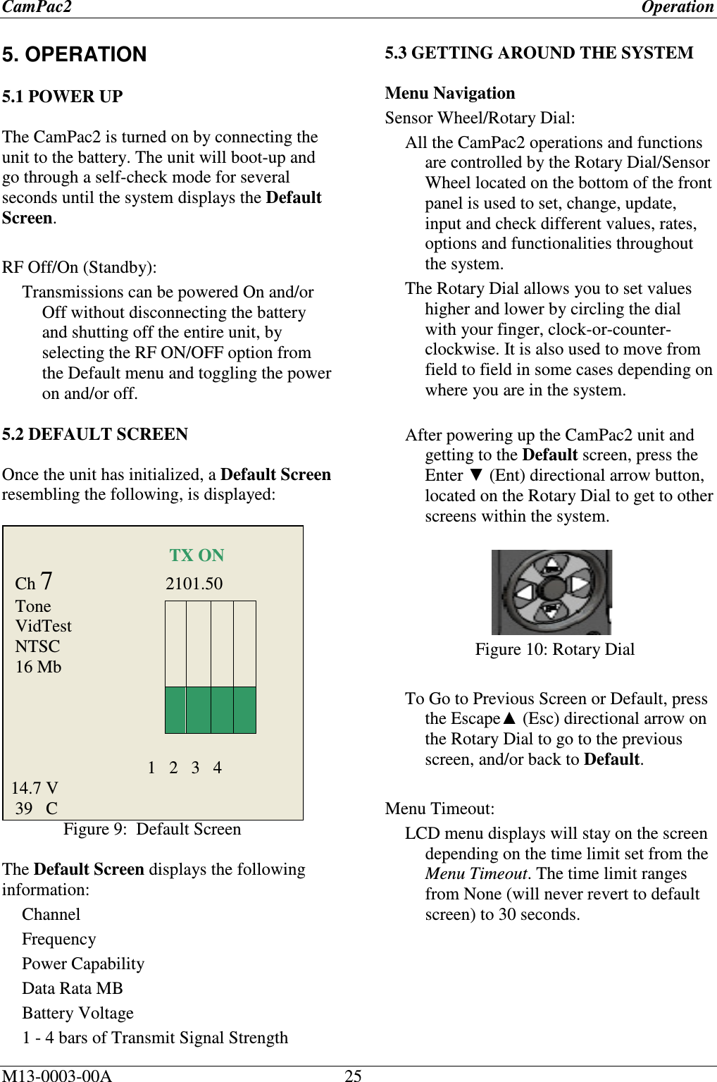
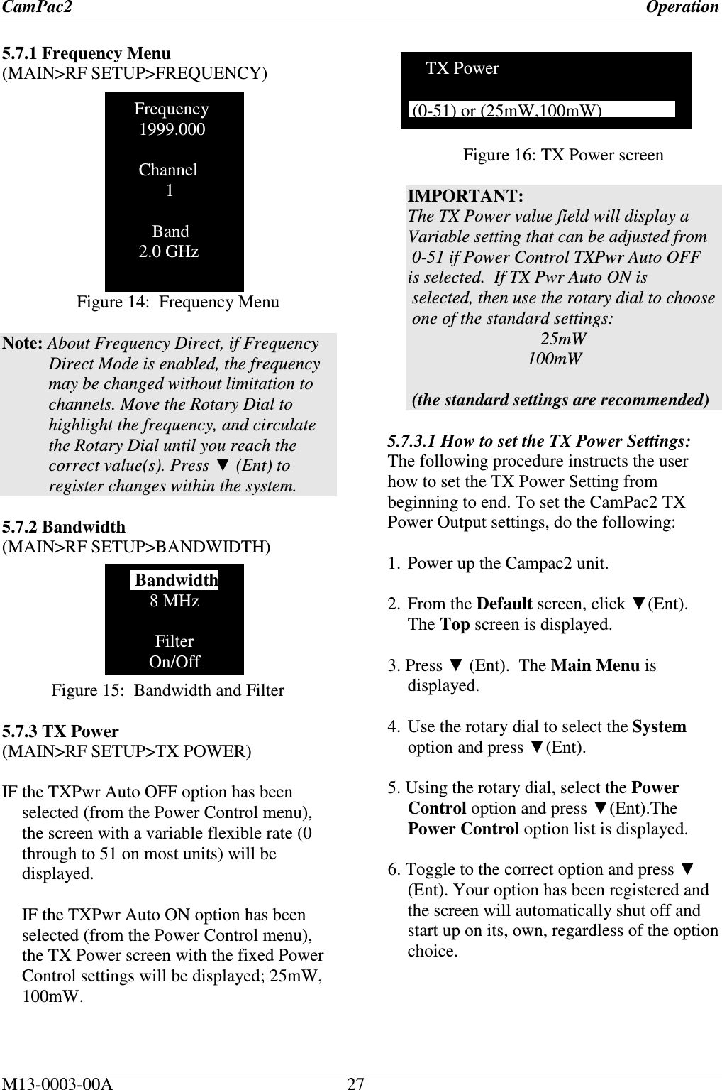
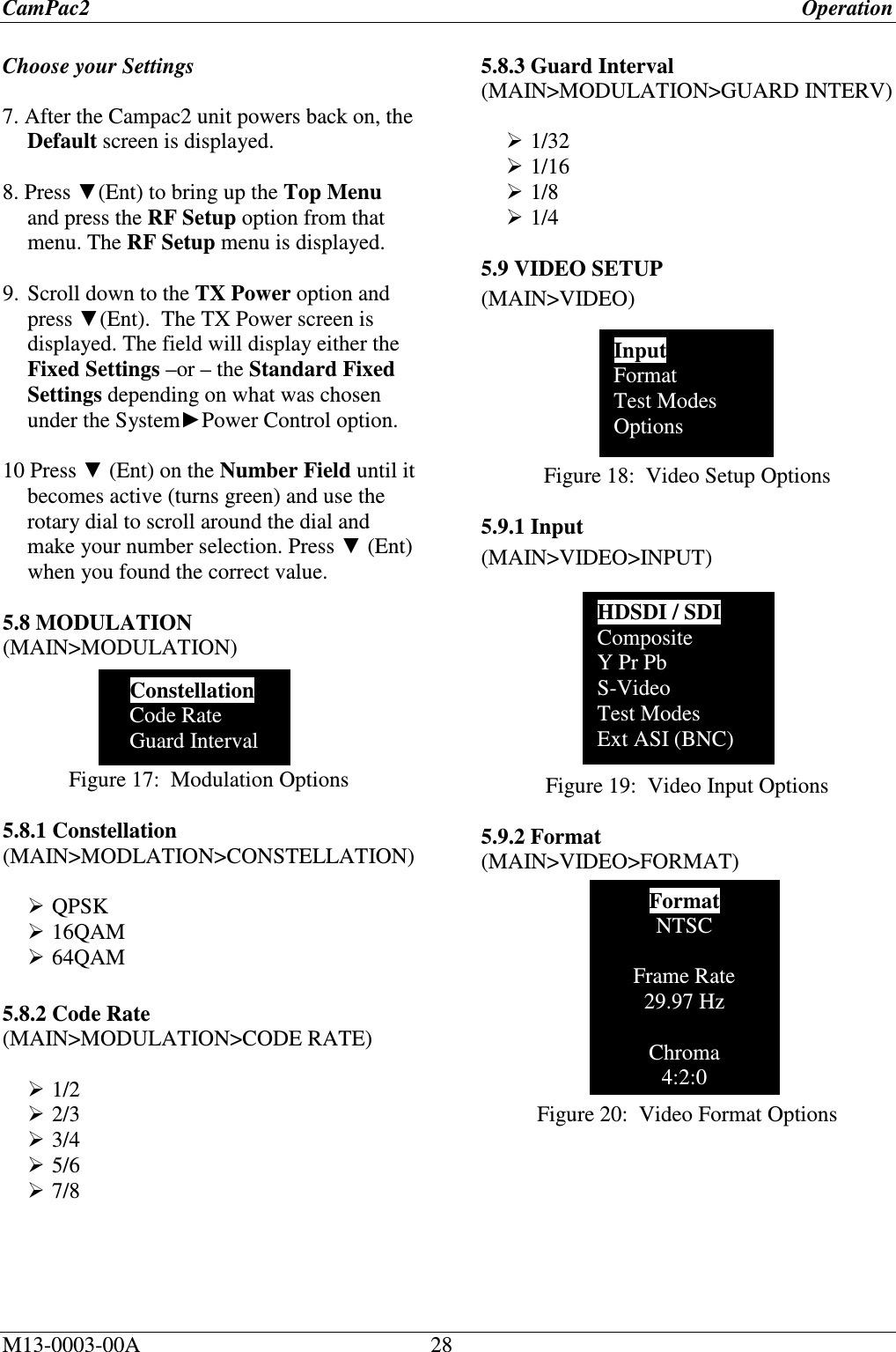
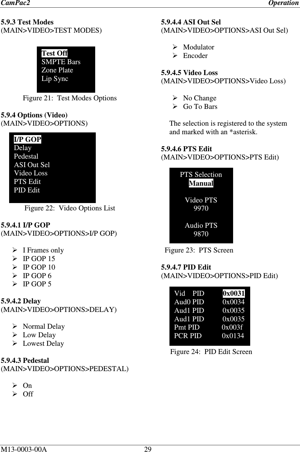
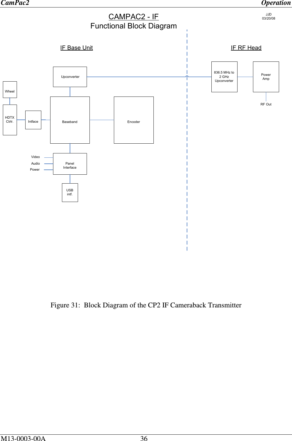
![CamPac2 Operation M13-0003-00A 26 Changing Settings: To change, view, input, select or update settings, values, rates, levels or options throughout most of the system, do the following 1. Select the desired menu or option by using the Rotary Dial and ENT button to reach the desired screen. Note: See the CamPac2 Menu Tree diagram at the end of this document for placement and location of all options. 2. Press ▼ (Ent) to view that menu’s options. 4. Continue to press ▼ (Ent), and drill down the menus until the value fields that need to be changed are displayed. 5. Click on the Value field until it becomes Active, (turns green). 6. Press the rotary dial, clockwise or counter- clockwise to select value fields up or down respectively –or- use the rotary dial to scroll up or down an options list to your choice with an *asterisk. The settings have been saved to the system. Note: If you are not choosing from an options list, then you will be setting the value from circulating the rotary wheel. These value fields need to be pressed until they turn green and become “active”, before they can be manipulated and data can be changed. When you reach the correct value, press [Enter] to save. 5.4 TOP MENU The Top Menu is reached by pressing ENT at the DEFAULT screen, once the unit is booted. Figure 11: Top Menu 5.6 MAIN MENU Figure 12: Main Menu 5.7 RF SETUP (MAIN>RF SETUP) Figure 13: RF Setup Menu RF Setup Modulation Video Setup Audio Setup Edit Presets System Alarms Frequency Bandwidth TX Power MAIN MENU PRESETS PWR ON RF OFF LOCK](https://usermanual.wiki/Integrated-Microwave-Technologies/58CP2/User-Guide-1300947-Page-26.png)
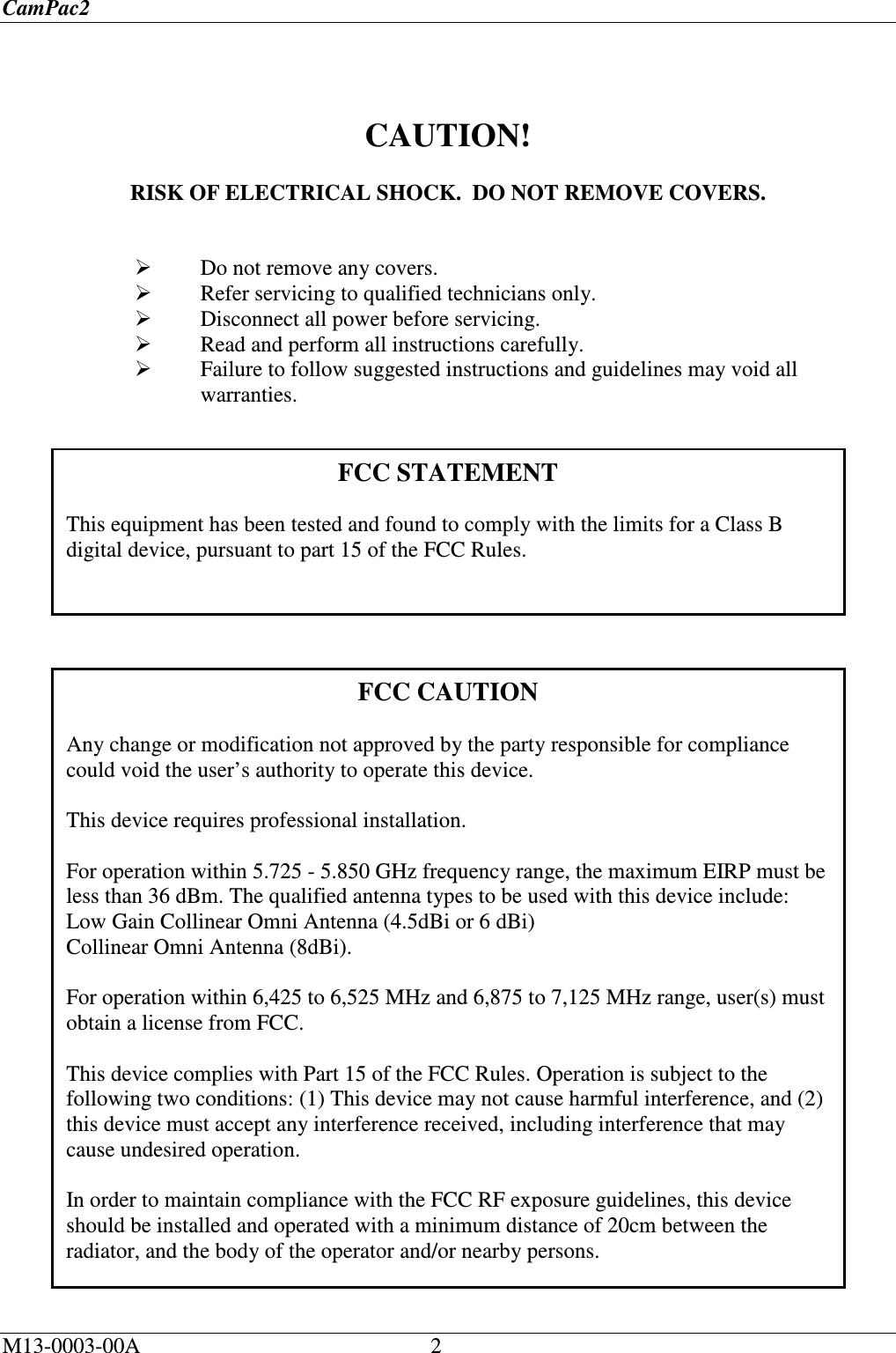
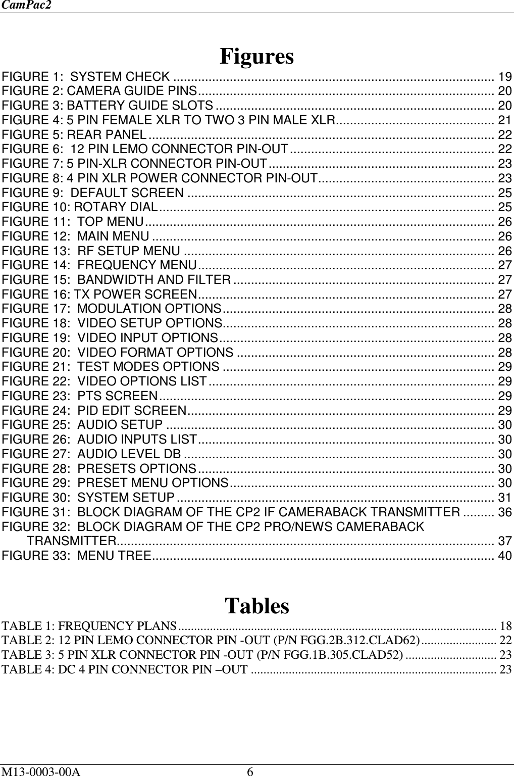
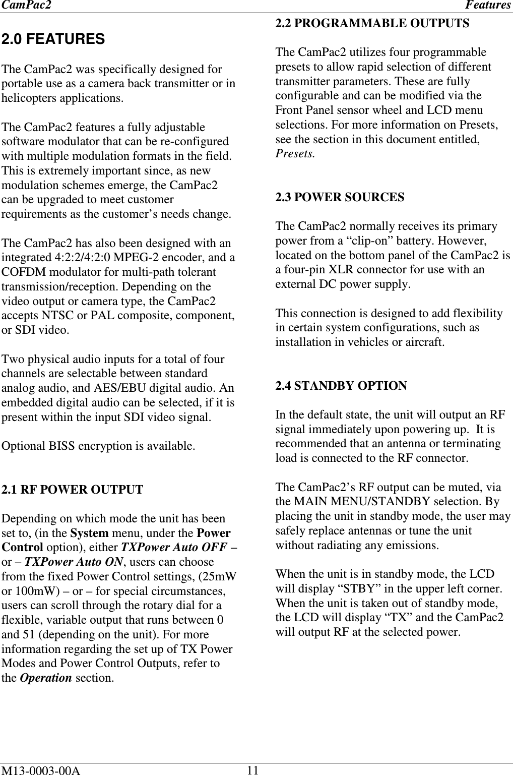
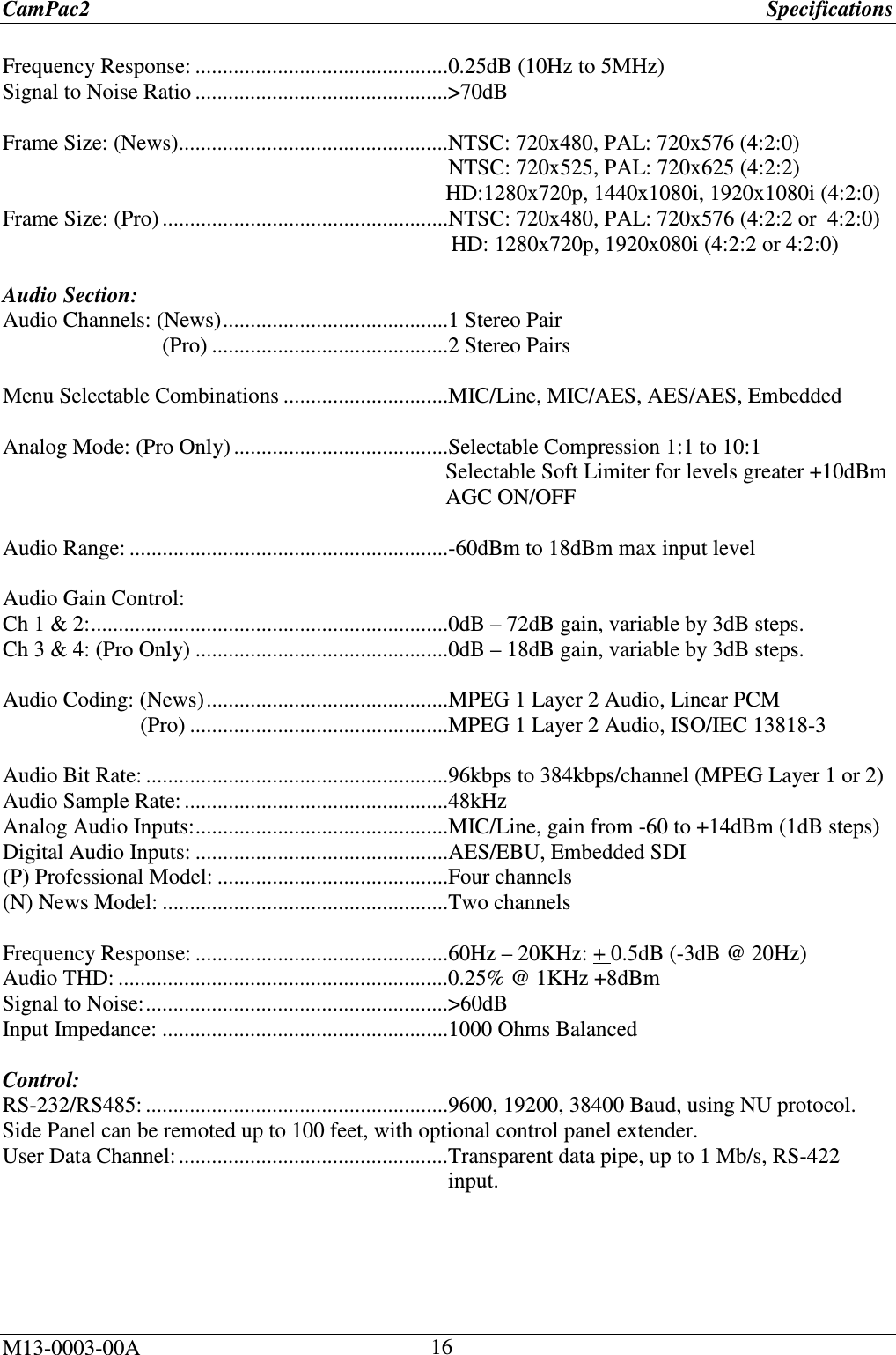
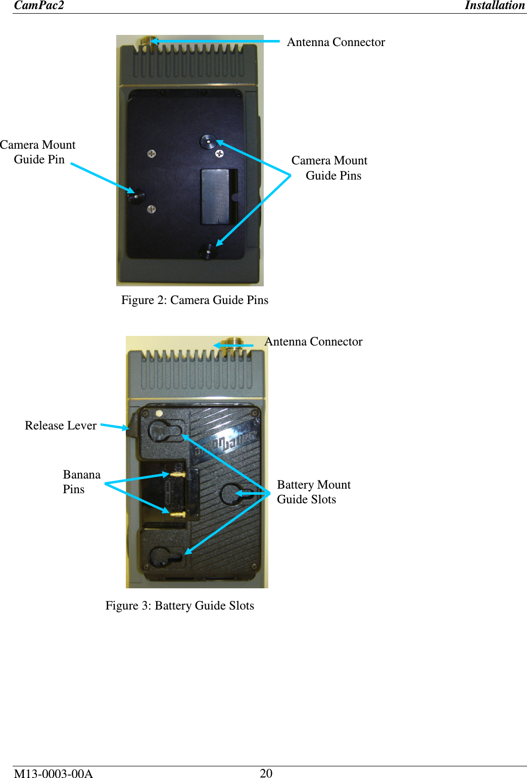
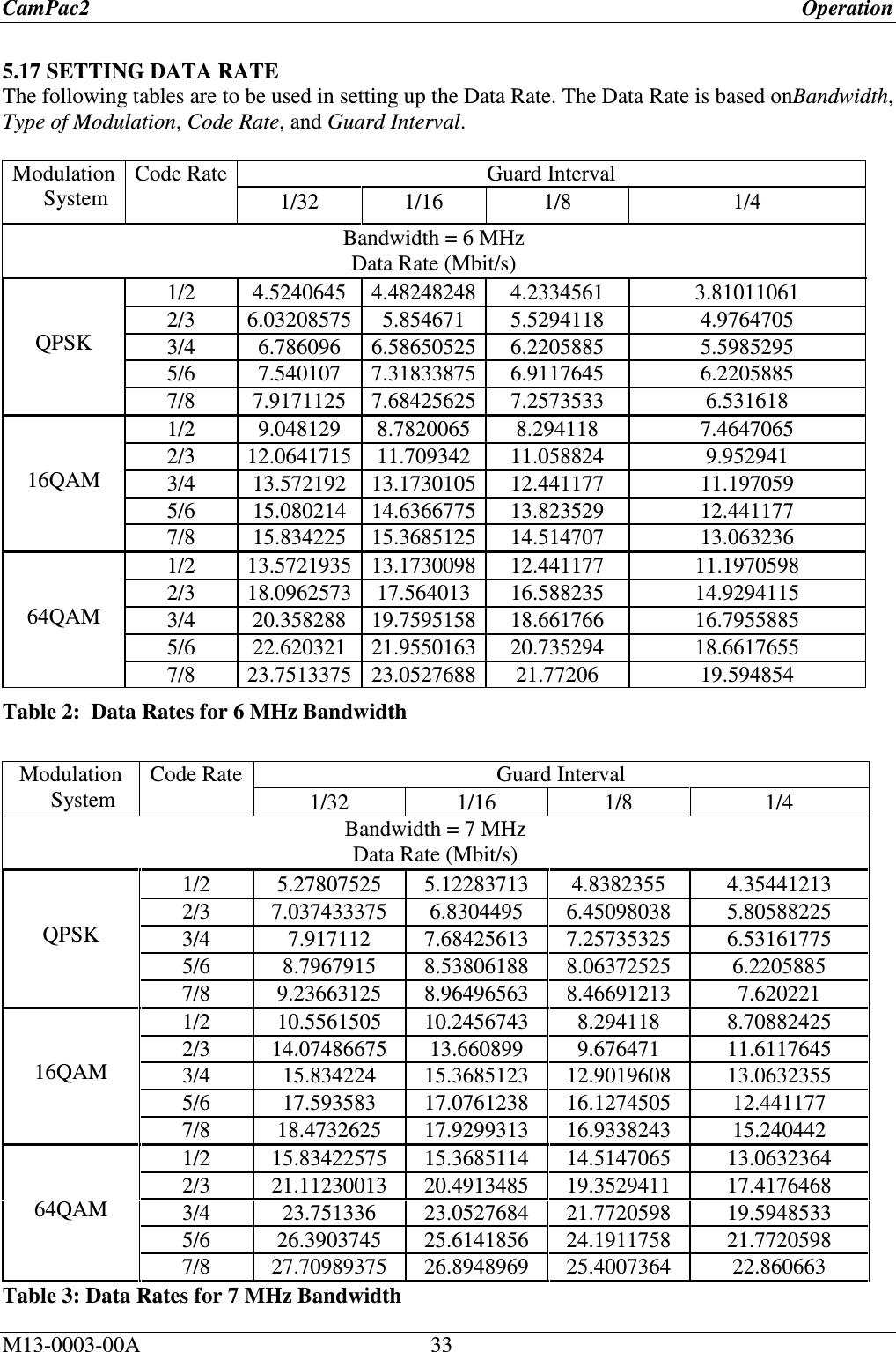
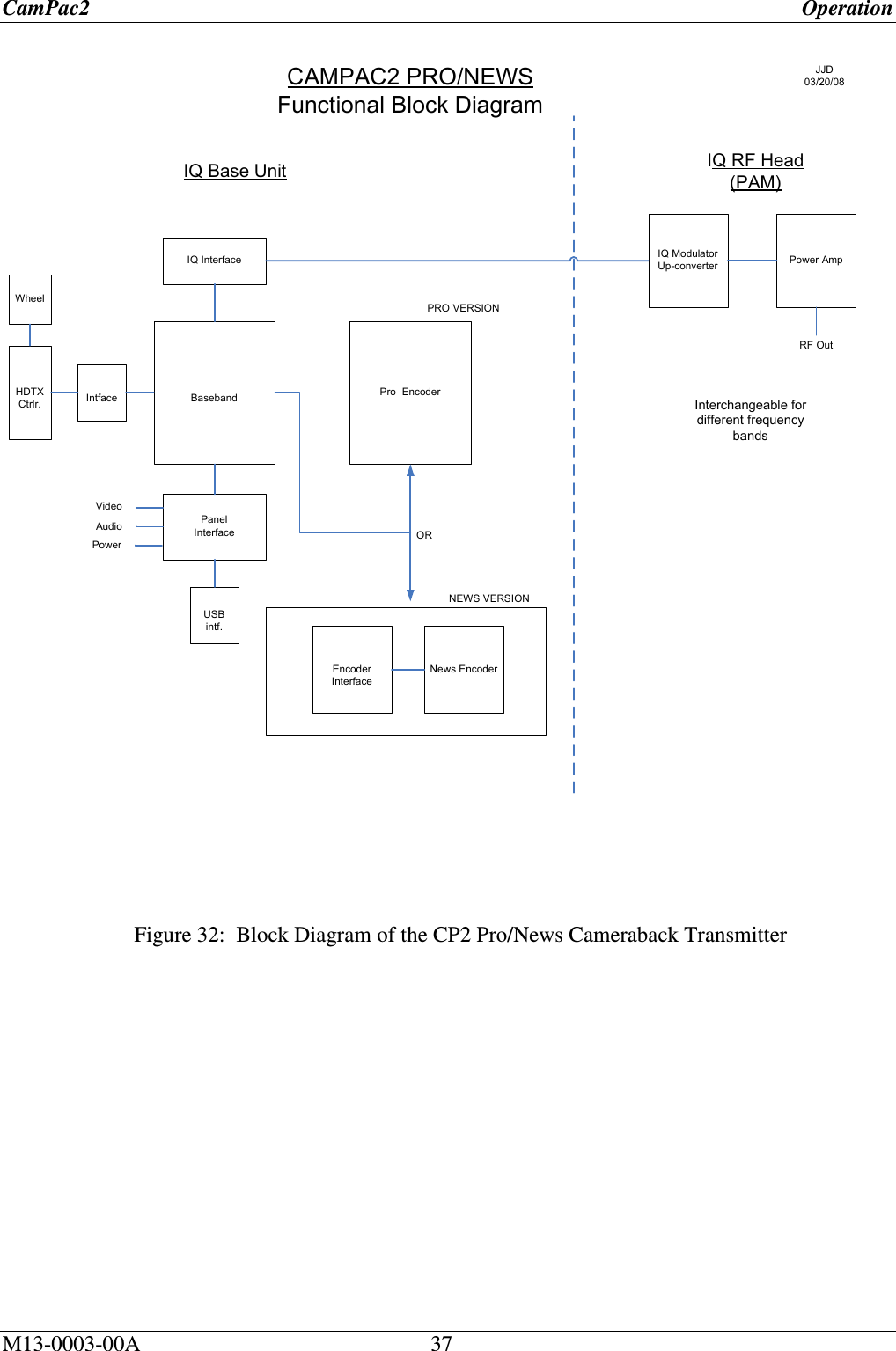
![CamPac2 Operation M13-0003-00A 30 5.10 AUDIO SETUP (MAIN>AUDIO) Figure 25: AUDIO Setup 5.10.1 Inputs (MAIN>AUDIO>INPUTS) Figure 26: Audio Inputs List 5.10.2 Audio Level dB (MAIN>AUDIO>Audio Level dB) Figure 27: Audio Level dB 5.11 PRESETS 5.11.1 Storing Presets (MAIN>EDIT PRESETS>PRESET 1-4) 1. Make your preferred settings. 2. From the MAIN Menu, select Edit Presets. Figure 28: Presets Options 3. Select the Preset to be saved, press ▼(Ent). Figure 29: Preset Menu Options 4. Select Store, then press ▼ (Ent) to save your new preset to the system. The Store screen is displayed, and reads: [Preset Stored]. 5.11.2 Naming (Labeling) Presets (MAIN>EDIT PRESETS>PRESET 1-4) 1. Using the rotary dial, scroll to the Name option and press ▼(Ent). The Preset name (originally 1 through 4) appears on the screen. 2. Press ▼ (Ent) to activate the Preset name field (it will turn green). The cursor appears on the first alpha-numeric character of the current name. 3. Press the rotary dial, clock –or-counter-clockwise to change the first character in the new label. 4. When you have reached the desired value (number or letter), press ▼ (Ent) –or- ► on the rotary dial to go to the next character in your label. Use the ◄ directional arrow on the rotary dial to backup if needed. 5. Repeat the procedure for the rest of the characters on this preset until the title has been created. 6. Press ▼ (Ent) and ▲(Esc) to register your label in the system. The label is displayed on the screen. Inputs Audio Level dB Mic/Lines Mic/AES AES/AES Embedded SDI Tone Beep Tone & Beep CH1: +0 CH2: +0 CH3: +0 CH4: + 0 PRESETS 1 PRESETS 2 PRESETS 3 PRESETS 4 Recall Store Name](https://usermanual.wiki/Integrated-Microwave-Technologies/58CP2/User-Guide-1300947-Page-30.png)
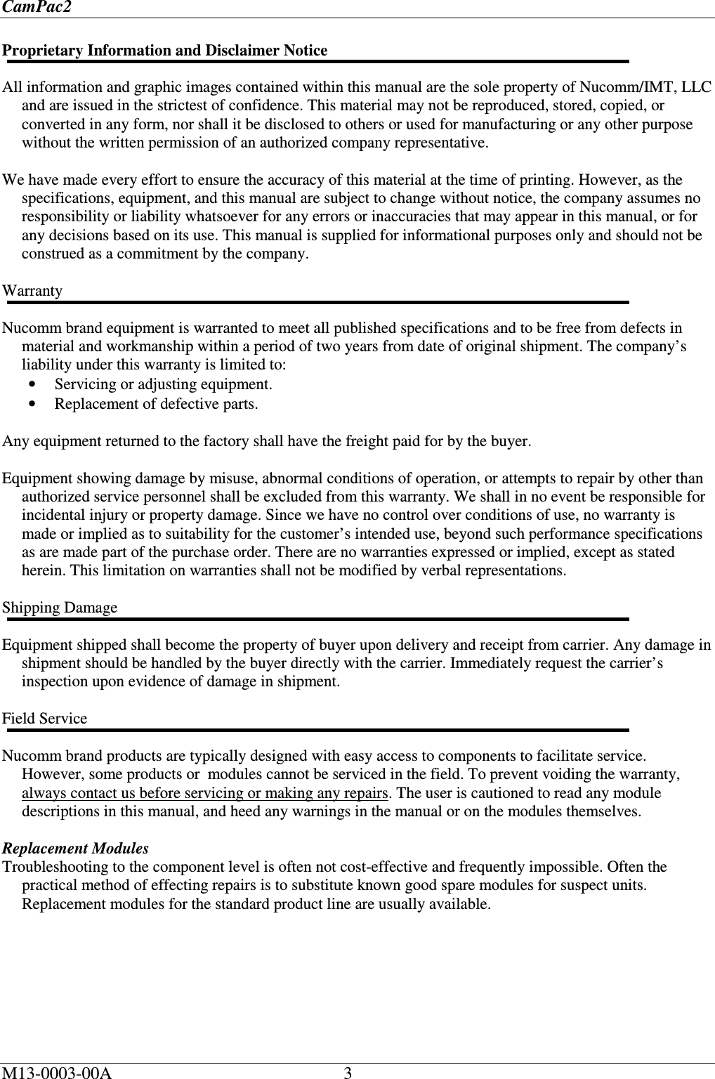
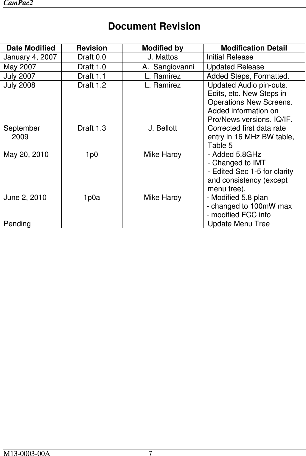
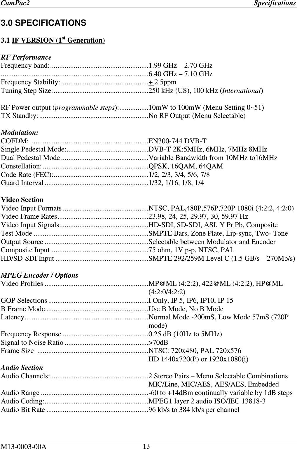
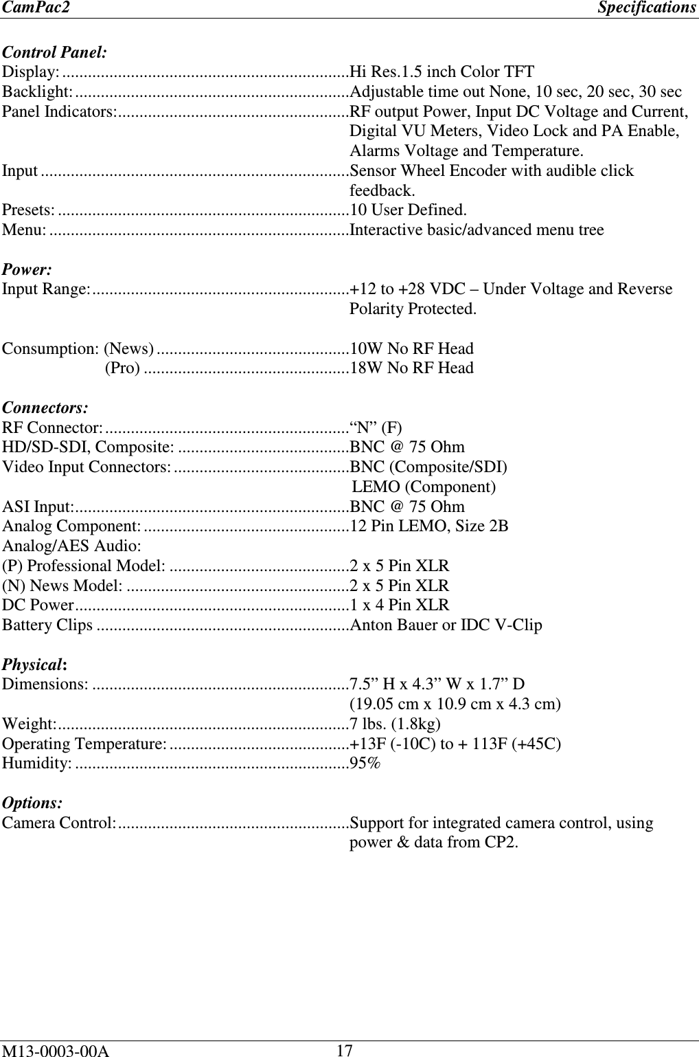
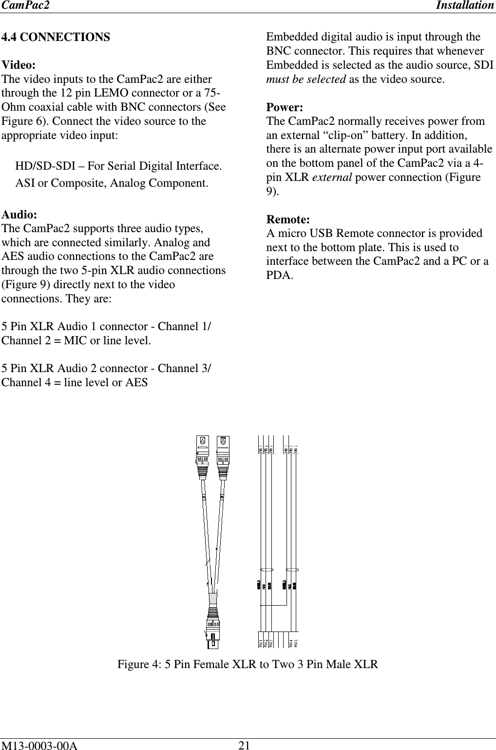
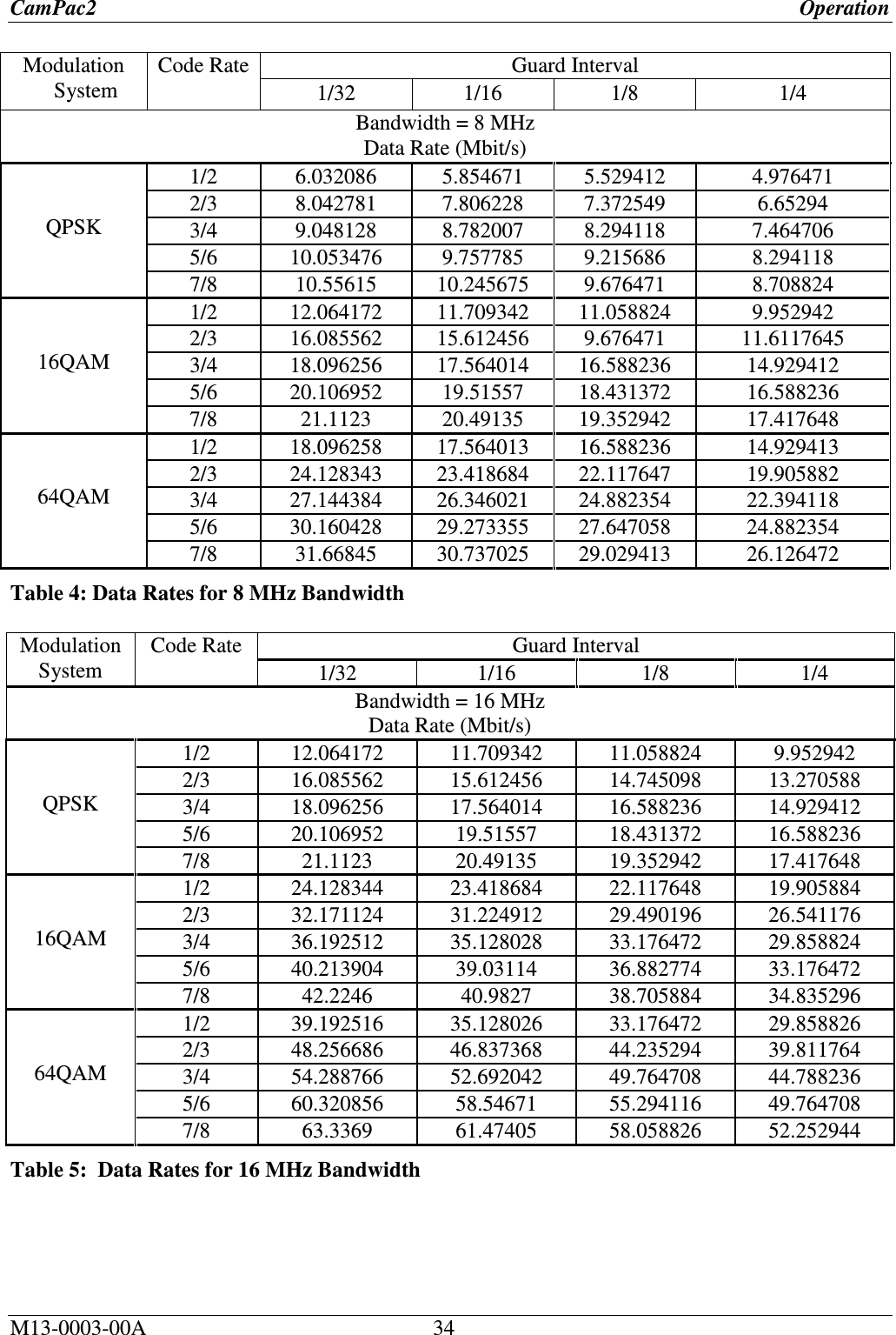
![CamPac2 Operation M13-0003-00A 31 5.11.3 Recalling Presets (MAIN>EDIT PRESETS>PRESET 1-4) 1. Using the rotary dial, scroll to the Recall option and press ▼(Ent). The Preset name (originally 1 through 4) appears on the screen. 2. Press ▼(Ent) to recall the preset and return to the Default screen. 5.12 SYSTEM (MAIN>SYSTEM) Figure 30: System Setup 5.12.1 Menu Timeout (MAIN>SYSTEM>Menu Timeout) None 10 Seconds 20 Seconds 30 Seconds The selection is marked by an *asterisk. 5.12.2 LCD Brightness (MAIN>SYSTEM>LCD Brightness) Day mode Night mode The selection is marked by an *asterisk. 5.12.3 RF Enable (MAIN>SYSTEM>RF Enable) Disable Enable 5.12.4 Power Control (MAIN>SYSTEM>Power Control) 5.12.5 Factory Default (MAIN>SYSTEM>Factory Default) Allows the user to restore factory defaults. WARNING: Any user settings will be over-written. No – resume ops Yes – defaults 5.12.6 TX Name (MAIN>SYSTEM>TX Name) The default transmitter name is “CAMPAC2”. To change the TX Name: 1. MAIN>SYSTEM>TX Name The current TX Name is displayed: [CAMPAC 2 ] 2. Click ▼ (Ent) to activate the “name” field. (Field turns green when ready for input). The cursor appears on the first character. 3. Use the rotary dial to scroll alpha-numeric characters, press ▼ (Ent) to select. 4. Use the ◄►arrows to select the next character, repeat until the name is updated. 5. Press ▼ (Ent) to save it to the system. Menu Timeout LCD Brightness RF Enable Power Control Factory Default TX Name SW Version Security Key](https://usermanual.wiki/Integrated-Microwave-Technologies/58CP2/User-Guide-1300947-Page-31.png)
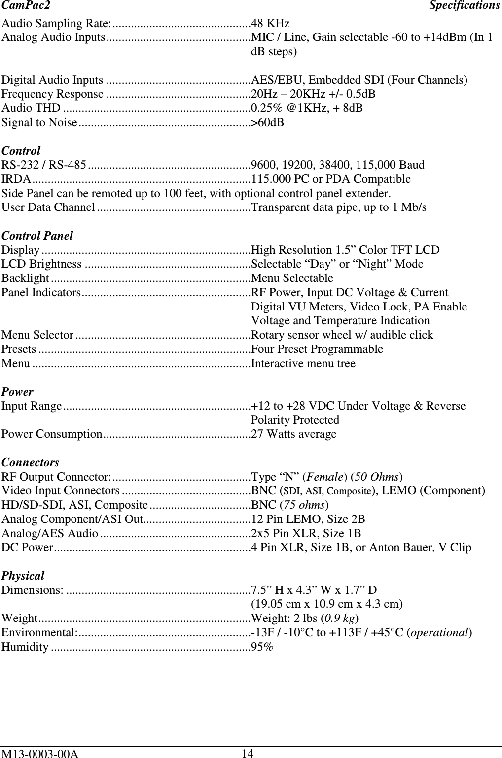
![CamPac2 Operation M13-0003-00A 32 5.12.7 SW Version (MAIN>SYSTEM>SW Version) Displays version numbers of the unit’s Side Panel, Baseband, Up Converter, and FPGA. 5.12.7 Security Key (MAIN>SYSTEM>Security Key) To set the system’s security key code (for HD/SD Enable/Disable), do the following: 1. To activate the screen, click ▼ (Ent). The field becomes active (turns green). 2. Using the rotary dial, set the correct code by scrolling the alpha-numeric characters until you reach the desired setting. 3. Use the ◄►arrows to move on to the next character of the Security Key code until the code has been set. 5. Press ▼ (Ent) to save the changes. 5.13 ALARMS (MAIN>ALARMS) This screen can provide information regarding some system errors if they should occur, and indicates the reason for any alarms. 1. To activate the screen, click ▼ (Ent). The field becomes active (turns green). 2. The Alarms indication list is displayed. If there were no Alarms indicated, there will be no alarms displayed on the screen. 5.14 POWER ON/RF OFF (Standby) (TOP>PWR ON) Allows the user to toggle the CamPac2 transmitter on and off (standby). Note: Depending on whether or not the unit is transmitting or on standby, POWER ON or RF OFF will be displayed, and a TX ON or RF SBY indicator will be displayed on the screen’s upper right hand corner. 5.15 SLEEP/RF OFF (TOP>RF OFF) To set the CamPac2 unit to SLEEP mode, or to set it to RF OFF mode if already in sleep mode, use the rotary dial to scroll down to the SLEEP –or-RF OFF option. Note: Depending on whether or not the unit is transmitting or on standby, the SLEEP or RF OFF indicator will be displayed on the screen’s upper right hand corner. 5.16 LOCK (TOP>LOCK) To lock the Campac2 unit so that settings remain “on hold” until you are ready to begin using it again: 1. Scroll down to the “Lock” option and press ▼ (Ent). 2. Hold the ▼ (Ent) button to lock the unit. The screen displays the message: [HOLD BUTTON TO UNLOCK]. 3. When you are ready to unlock the unit, hold down the ▼ (Ent) button until the “Top” First Menu re-appears. 4. The system is unlocked. The settings are the same as when the system was locked.](https://usermanual.wiki/Integrated-Microwave-Technologies/58CP2/User-Guide-1300947-Page-32.png)
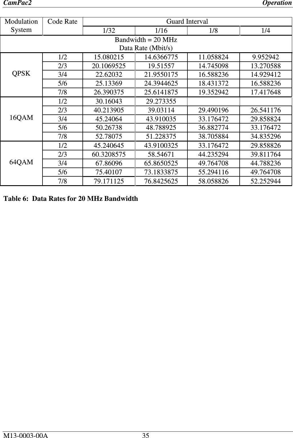
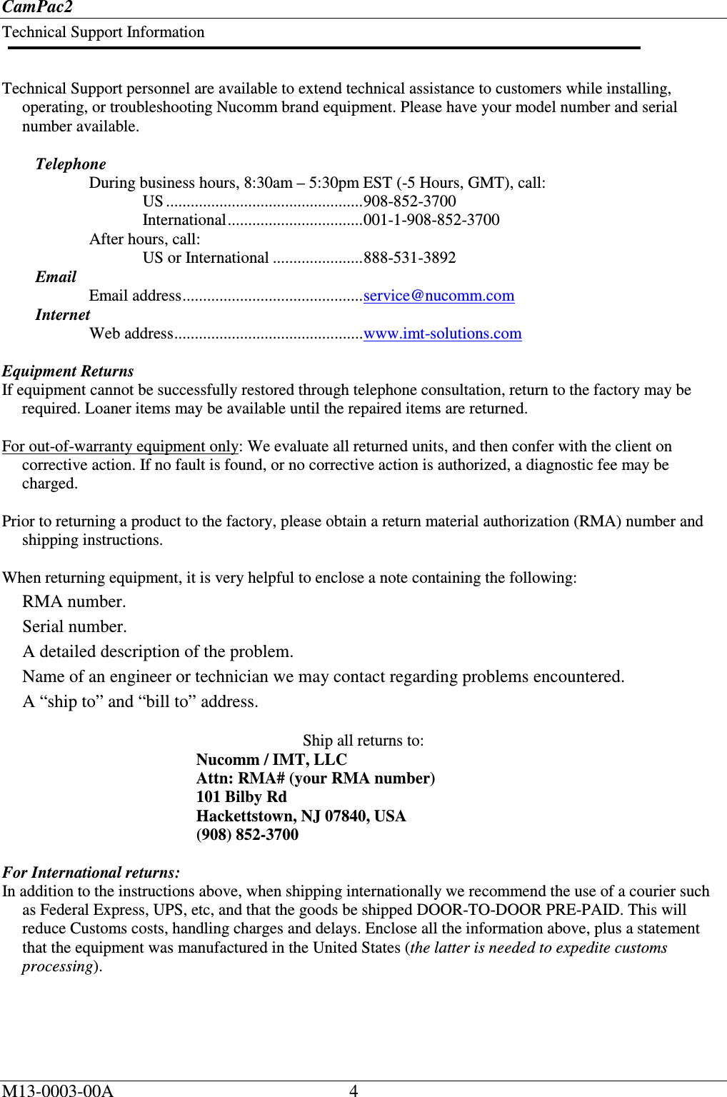
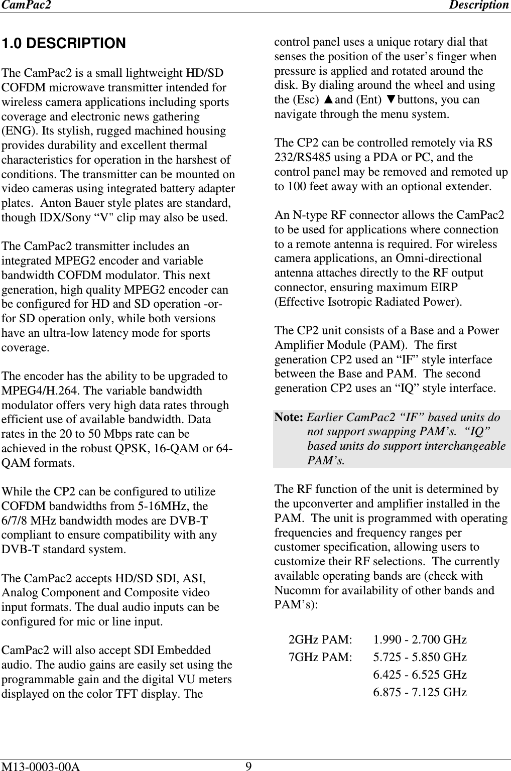
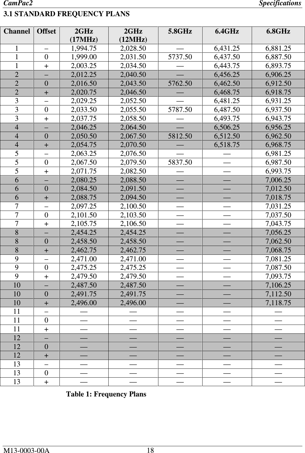
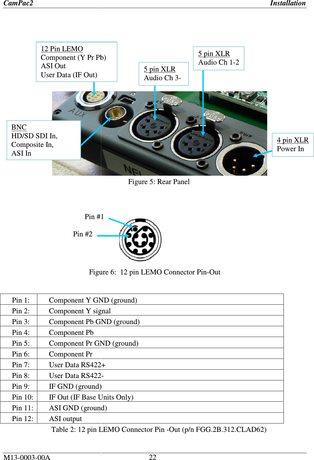
![CamPac2 Menu Tree M13-0003-00A 40 5.18 MENU TREE Figure 33: Menu TreeLOCKRF OFF/RF ONPRESETSMAIN MENU/TOP MENU SLEEP/PWR ONHOLD BUTTON TO UNLOCKDEFAULT SCREENPRESET 1PRESET 2PRESET 3PRESET 4DEFAULT SCREENModulation Video SetupRF Setup Audio Setup Edit Presets System AlarmsFrequency: Frequency [Freq Range] Channel: [Channel range]Band: [Band GHz range]Bandwidth: Bandwidth [MHz Range]Filter: (On/Off)TX Power: TX Power [TX power range]Constellation: (QPSK, 16QAM, 64QAM)Code Rate: 1/2, 2/3,3/4, 5/6, 7/8)Guard Interval: (1/32, 1/16, 1/8,1/4) (Test Off, SMPTE Bars, Zone Plate Lip Sync)IP/GOP:(I Frames only, IP GOP 15, IP GOP 10, IP GOP 6, IP GOP 5)(NTSC, PAL, 480P, 576P, 720P, 1080i, 1080PsF)Frame Rate: (Rate)Chroma: (4:2:0-4:2:2)Presets 1-4RecallStoreNameMenu Timeout: (None, 10, 20, 30 Seconds).LCD Brightness: (Day mode, Night mode).RF Enable: (Disable, Enable).Power Control: (TXPwr Auto OFF, TXPwr Auto ON).Factory Default: (No-resume ops, Yes-defaults).Telemetry: (Enable, Disable).TX Name: (CAMPAC2 -Label). SW Version: (Sidepanel, Baseband, UpConverter, FPGA).Security Key: (Serial Number, Enter Key, HD Licensed).Lists any alarm indications(HD/SDI, Composite, Y Pr Pb, S-Video, Test ModesExt ASI (BNC)INPUT FORMAT TEST MODESOptionsDelay:NormalLowLowest DelayPedestal:On/Off ASI Out Sel:ModulatorEncoderVideo Loss:No ChangeGo to BarsPTS Edit:PTS Selection (Manual/Automatic)Video PTS [Range]Audio PTS (Range)PID Edit:Vid PID 0x0031 (Set to Range)Aud0 PID 0x0034 (Set to Range)Aud1 PID 0x0035 (Set to Range)PMT PID 0x003f (Set to Range)PCR PID 0x0134 (Set to Range)Inputs: (Mic/Line, Mic/AES, AES/AES, Embedded SDI, Tone, Beef, Tone & Beep).Audio Level dB:CH1: (Range)CH2: (Range)CH3: (Range)CH4: (Range)Limiter:CH1: (On/Off)CH2: (On./Off)Gang (On/Off)Phantom:CH1: (On/Off)CH2: (On/Off)](https://usermanual.wiki/Integrated-Microwave-Technologies/58CP2/User-Guide-1300947-Page-40.png)