Integrated Microwave Technologies 58CP2 5.8GHz CAMPAC2 User Manual
Integrated Microwave Technologies, LLC. 5.8GHz CAMPAC2
User Manual
CAMPAC2
COFDM Camera-Back Transmitter,
User Manual
M13-0003-00A; Rev 1p0a
Integrated Microwave Technologies, LLC
101 Bilby Road
Hackettstown, NJ 07840
Tel: 908-852-3700 Fax: 908-813-0399
www.imt-solutions.com

CamPac2
M13-0003-00A 2
FCC STATEMENT
This equipment has been tested and found to comply with the limits for a Class B
digital device, pursuant to part 15 of the FCC Rules.
FCC CAUTION
Any change or modification not approved by the party responsible for compliance
could void the user’s authority to operate this device.
This device requires professional installation.
For operation within 5.725 - 5.850 GHz frequency range, the maximum EIRP must be
less than 36 dBm. The qualified antenna types to be used with this device include:
Low Gain Collinear Omni Antenna (4.5dBi or 6 dBi)
Collinear Omni Antenna (8dBi).
For operation within 6,425 to 6,525 MHz and 6,875 to 7,125 MHz range, user(s) must
obtain a license from FCC.
This device complies with Part 15 of the FCC Rules. Operation is subject to the
following two conditions: (1) This device may not cause harmful interference, and (2)
this device must accept any interference received, including interference that may
cause undesired operation.
In order to maintain compliance with the FCC RF exposure guidelines, this device
should be installed and operated with a minimum distance of 20cm between the
radiator, and the body of the operator and/or nearby persons.
CAUTION!
RISK OF ELECTRICAL SHOCK. DO NOT REMOVE COVERS.
Do not remove any covers.
Refer servicing to qualified technicians only.
Disconnect all power before servicing.
Read and perform all instructions carefully.
Failure to follow suggested instructions and guidelines may void all
warranties.

CamPac2
M13-0003-00A 3
Proprietary Information and Disclaimer Notice
All information and graphic images contained within this manual are the sole property of Nucomm/IMT, LLC
and are issued in the strictest of confidence. This material may not be reproduced, stored, copied, or
converted in any form, nor shall it be disclosed to others or used for manufacturing or any other purpose
without the written permission of an authorized company representative.
We have made every effort to ensure the accuracy of this material at the time of printing. However, as the
specifications, equipment, and this manual are subject to change without notice, the company assumes no
responsibility or liability whatsoever for any errors or inaccuracies that may appear in this manual, or for
any decisions based on its use. This manual is supplied for informational purposes only and should not be
construed as a commitment by the company.
Warranty
Nucomm brand equipment is warranted to meet all published specifications and to be free from defects in
material and workmanship within a period of two years from date of original shipment. The company’s
liability under this warranty is limited to:
• Servicing or adjusting equipment.
• Replacement of defective parts.
Any equipment returned to the factory shall have the freight paid for by the buyer.
Equipment showing damage by misuse, abnormal conditions of operation, or attempts to repair by other than
authorized service personnel shall be excluded from this warranty. We shall in no event be responsible for
incidental injury or property damage. Since we have no control over conditions of use, no warranty is
made or implied as to suitability for the customer’s intended use, beyond such performance specifications
as are made part of the purchase order. There are no warranties expressed or implied, except as stated
herein. This limitation on warranties shall not be modified by verbal representations.
Shipping Damage
Equipment shipped shall become the property of buyer upon delivery and receipt from carrier. Any damage in
shipment should be handled by the buyer directly with the carrier. Immediately request the carrier’s
inspection upon evidence of damage in shipment.
Field Service
Nucomm brand products are typically designed with easy access to components to facilitate service.
However, some products or modules cannot be serviced in the field. To prevent voiding the warranty,
always contact us before servicing or making any repairs. The user is cautioned to read any module
descriptions in this manual, and heed any warnings in the manual or on the modules themselves.
Replacement Modules
Troubleshooting to the component level is often not cost-effective and frequently impossible. Often the
practical method of effecting repairs is to substitute known good spare modules for suspect units.
Replacement modules for the standard product line are usually available.

CamPac2
M13-0003-00A 4
Technical Support Information
Technical Support personnel are available to extend technical assistance to customers while installing,
operating, or troubleshooting Nucomm brand equipment. Please have your model number and serial
number available.
Telephone
During business hours, 8:30am – 5:30pm EST (-5 Hours, GMT), call:
US ................................................ 908-852-3700
International ................................. 001-1-908-852-3700
After hours, call:
US or International ...................... 888-531-3892
Email
Email address ............................................ service@nucomm.com
Internet
Web address .............................................. www.imt-solutions.com
Equipment Returns
If equipment cannot be successfully restored through telephone consultation, return to the factory may be
required. Loaner items may be available until the repaired items are returned.
For out-of-warranty equipment only: We evaluate all returned units, and then confer with the client on
corrective action. If no fault is found, or no corrective action is authorized, a diagnostic fee may be
charged.
Prior to returning a product to the factory, please obtain a return material authorization (RMA) number and
shipping instructions.
When returning equipment, it is very helpful to enclose a note containing the following:
RMA number.
Serial number.
A detailed description of the problem.
Name of an engineer or technician we may contact regarding problems encountered.
A “ship to” and “bill to” address.
Ship all returns to:
Nucomm / IMT, LLC
Attn: RMA# (your RMA number)
101 Bilby Rd
Hackettstown, NJ 07840, USA
(908) 852-3700
For International returns:
In addition to the instructions above, when shipping internationally we recommend the use of a courier such
as Federal Express, UPS, etc, and that the goods be shipped DOOR-TO-DOOR PRE-PAID. This will
reduce Customs costs, handling charges and delays. Enclose all the information above, plus a statement
that the equipment was manufactured in the United States (the latter is needed to expedite customs
processing).

CamPac2
M13-0003-00A 5
Table of Contents
1.0 DESCRIPTION............................................................................................................................... 9
2.0 FEATURES .................................................................................................................................. 11
2.1 RF POWER OUTPUT ............................................................................................................. 11
2.2 PROGRAMMABLE OUTPUTS ............................................................................................. 11
2.3 POWER SOURCES ................................................................................................................. 11
2.4 STANDBY OPTION ............................................................................................................... 11
3.0 SPECIFICATIONS ....................................................................................................................... 13
3.1 STANDARD FREQUENCY PLANS ..................................................................................... 18
4.0 INSTALLATION ......................................................................................................................... 19
4.1 UNPACKING AND INSPECTION ........................................................................................ 19
4.2 PRE-INSTALLATION CHECK ............................................................................................. 19
4.3 MECHANICAL INSTALLATION ......................................................................................... 19
4.4 CONNECTIONS ..................................................................................................................... 21
Video: ........................................................................................................................................ 21
Audio: ........................................................................................................................................ 21
5. OPERATION .................................................................................................................................. 25
5.1 POWER UP .............................................................................................................................. 25
5.2 DEFAULT SCREEN ............................................................................................................... 25
5.3 GETTING AROUND THE SYSTEM ..................................................................................... 25
5.4 TOP MENU ............................................................................................................................. 26
5.6 MAIN MENU .......................................................................................................................... 26
5.7 RF SETUP ................................................................................................................................ 26
5.7.2 Bandwidth ............................................................................................................................. 27
5.8 MODULATION ....................................................................................................................... 28
5.9 VIDEO SETUP ........................................................................................................................ 28
5.10 AUDIO SETUP ...................................................................................................................... 30
5.11 PRESETS .............................................................................................................................. 30
5.12 SYSTEM ................................................................................................................................ 31
5.13 ALARMS ............................................................................................................................... 32
5.14 POWER ON/RF OFF (Standby) ............................................................................................ 32
5.15 SLEEP/RF OFF ...................................................................................................................... 32
5.16 LOCK ..................................................................................................................................... 32
5.17 SETTING DATA RATE........................................................................................................ 33
TERMS & DEFINITIONS ................................................................................................................. 38
5.18 MENU TREE ......................................................................................................................... 40

CamPac2
M13-0003-00A 6
Figures
FIGURE 1: SYSTEM CHECK ........................................................................................... 19
FIGURE 2: CAMERA GUIDE PINS .................................................................................... 20
FIGURE 3: BATTERY GUIDE SLOTS ............................................................................... 20
FIGURE 4: 5 PIN FEMALE XLR TO TWO 3 PIN MALE XLR ............................................. 21
FIGURE 5: REAR PANEL .................................................................................................. 22
FIGURE 6: 12 PIN LEMO CONNECTOR PIN-OUT .......................................................... 22
FIGURE 7: 5 PIN-XLR CONNECTOR PIN-OUT ................................................................ 23
FIGURE 8: 4 PIN XLR POWER CONNECTOR PIN-OUT .................................................. 23
FIGURE 9: DEFAULT SCREEN ....................................................................................... 25
FIGURE 10: ROTARY DIAL ............................................................................................... 25
FIGURE 11: TOP MENU ................................................................................................... 26
FIGURE 12: MAIN MENU ................................................................................................. 26
FIGURE 13: RF SETUP MENU ........................................................................................ 26
FIGURE 14: FREQUENCY MENU .................................................................................... 27
FIGURE 15: BANDWIDTH AND FILTER .......................................................................... 27
FIGURE 16: TX POWER SCREEN .................................................................................... 27
FIGURE 17: MODULATION OPTIONS ............................................................................. 28
FIGURE 18: VIDEO SETUP OPTIONS ............................................................................. 28
FIGURE 19: VIDEO INPUT OPTIONS .............................................................................. 28
FIGURE 20: VIDEO FORMAT OPTIONS ......................................................................... 28
FIGURE 21: TEST MODES OPTIONS ............................................................................. 29
FIGURE 22: VIDEO OPTIONS LIST ................................................................................. 29
FIGURE 23: PTS SCREEN ............................................................................................... 29
FIGURE 24: PID EDIT SCREEN ....................................................................................... 29
FIGURE 25: AUDIO SETUP ............................................................................................. 30
FIGURE 26: AUDIO INPUTS LIST .................................................................................... 30
FIGURE 27: AUDIO LEVEL DB ........................................................................................ 30
FIGURE 28: PRESETS OPTIONS .................................................................................... 30
FIGURE 29: PRESET MENU OPTIONS ........................................................................... 30
FIGURE 30: SYSTEM SETUP .......................................................................................... 31
FIGURE 31: BLOCK DIAGRAM OF THE CP2 IF CAMERABACK TRANSMITTER ......... 36
FIGURE 32: BLOCK DIAGRAM OF THE CP2 PRO/NEWS CAMERABACK
TRANSMITTER ........................................................................................................... 37
FIGURE 33: MENU TREE ................................................................................................. 40
Tables
TABLE 1: FREQUENCY PLANS ..................................................................................................... 18
TABLE 2: 12 PIN LEMO CONNECTOR PIN -OUT (P/N FGG.2B.312.CLAD62) ........................ 22
TABLE 3: 5 PIN XLR CONNECTOR PIN -OUT (P/N FGG.1B.305.CLAD52) ............................. 23
TABLE 4: DC 4 PIN CONNECTOR PIN –OUT .............................................................................. 23

CamPac2
M13-0003-00A 7
Document Revision
Date Modified
Revision
Modified b
y
Modification Detail
January 4, 2007 Draft 0.0 J. Mattos Initial Release
May 2007 Draft 1.0 A. Sangiovanni Updated Release
July 2007 Draft 1.1 L. Ramirez Added Steps, Formatted.
July 2008 Draft 1.2 L. Ramirez Updated Audio pin-outs.
Edits, etc. New Steps in
Operations New Screens.
Added information on
Pro/News versions. IQ/IF.
September
2009
Draft 1.3
J. Bellott
Corrected first data rate
entry in 16 MHz BW table,
Table 5
May 20, 2010 1p0 Mike Hardy - Added 5.8GHz
- Changed to IMT
- Edited Sec 1-5 for clarity
and consistency (except
menu tree).
June 2, 2010 1p0a Mike Hardy - Modified 5.8 plan
- changed to 100mW max
- modified FCC info
Pending Update Menu Tree

CamPac2 Description
M13-0003-00A 8

CamPac2 Description
M13-0003-00A 9
1.0 DESCRIPTION
The CamPac2 is a small lightweight HD/SD
COFDM microwave transmitter intended for
wireless camera applications including sports
coverage and electronic news gathering
(ENG). Its stylish, rugged machined housing
provides durability and excellent thermal
characteristics for operation in the harshest of
conditions. The transmitter can be mounted on
video cameras using integrated battery adapter
plates. Anton Bauer style plates are standard,
though IDX/Sony “V" clip may also be used.
The CamPac2 transmitter includes an
integrated MPEG2 encoder and variable
bandwidth COFDM modulator. This next
generation, high quality MPEG2 encoder can
be configured for HD and SD operation -or-
for SD operation only, while both versions
have an ultra-low latency mode for sports
coverage.
The encoder has the ability to be upgraded to
MPEG4/H.264. The variable bandwidth
modulator offers very high data rates through
efficient use of available bandwidth. Data
rates in the 20 to 50 Mbps rate can be
achieved in the robust QPSK, 16-QAM or 64-
QAM formats.
While the CP2 can be configured to utilize
COFDM bandwidths from 5-16MHz, the
6/7/8 MHz bandwidth modes are DVB-T
compliant to ensure compatibility with any
DVB-T standard system.
The CamPac2 accepts HD/SD SDI, ASI,
Analog Component and Composite video
input formats. The dual audio inputs can be
configured for mic or line input.
CamPac2 will also accept SDI Embedded
audio. The audio gains are easily set using the
programmable gain and the digital VU meters
displayed on the color TFT display. The
control panel uses a unique rotary dial that
senses the position of the user’s finger when
pressure is applied and rotated around the
disk. By dialing around the wheel and using
the (Esc) ▲and (Ent) ▼buttons, you can
navigate through the menu system.
The CP2 can be controlled remotely via RS
232/RS485 using a PDA or PC, and the
control panel may be removed and remoted up
to 100 feet away with an optional extender.
An N-type RF connector allows the CamPac2
to be used for applications where connection
to a remote antenna is required. For wireless
camera applications, an Omni-directional
antenna attaches directly to the RF output
connector, ensuring maximum EIRP
(Effective Isotropic Radiated Power).
The CP2 unit consists of a Base and a Power
Amplifier Module (PAM). The first
generation CP2 used an “IF” style interface
between the Base and PAM. The second
generation CP2 uses an “IQ” style interface.
Note: Earlier CamPac2 “IF” based units do
not support swapping PAM’s. “IQ”
based units do support interchangeable
PAM’s.
The RF function of the unit is determined by
the upconverter and amplifier installed in the
PAM. The unit is programmed with operating
frequencies and frequency ranges per
customer specification, allowing users to
customize their RF selections. The currently
available operating bands are (check with
Nucomm for availability of other bands and
PAM’s):
2GHz PAM: 1.990 - 2.700 GHz
7GHz PAM: 5.725 - 5.850 GHz
6.425 - 6.525 GHz
6.875 - 7.125 GHz

CamPac2 Description
M13-0003-00A 10
The “IQ” based CP2 can be factory configured
for either News or Professional use,
depending on the encoder style installed in the
Base. This configuration is not field
selectable or swappable, and the customer
must specify either the “N” or the “P” style
when ordering.
The News (N) style CP2 supports very low
latency operation as required by broadcasters
for live shots, with superb fidelity. The
Professional (P) style CP2 favors exquisite
fidelity over low latency, as desired for non-
live applications.
In an IQ based unit, the Base outputs a digital
IQ modulated signal. The PAM receives the
IQ signal and converts it to the final RF output
frequency
.

CamPac2 Features
M13-0003-00A 11
2.0 FEATURES
The CamPac2 was specifically designed for
portable use as a camera back transmitter or in
helicopters applications.
The CamPac2 features a fully adjustable
software modulator that can be re-configured
with multiple modulation formats in the field.
This is extremely important since, as new
modulation schemes emerge, the CamPac2
can be upgraded to meet customer
requirements as the customer’s needs change.
The CamPac2 has also been designed with an
integrated 4:2:2/4:2:0 MPEG-2 encoder, and a
COFDM modulator for multi-path tolerant
transmission/reception. Depending on the
video output or camera type, the CamPac2
accepts NTSC or PAL composite, component,
or SDI video.
Two physical audio inputs for a total of four
channels are selectable between standard
analog audio, and AES/EBU digital audio. An
embedded digital audio can be selected, if it is
present within the input SDI video signal.
Optional BISS encryption is available.
2.1 RF POWER OUTPUT
Depending on which mode the unit has been
set to, (in the System menu, under the Power
Control option), either TXPower Auto OFF –
or – TXPower Auto ON, users can choose
from the fixed Power Control settings, (25mW
or 100mW) – or – for special circumstances,
users can scroll through the rotary dial for a
flexible, variable output that runs between 0
and 51 (depending on the unit). For more
information regarding the set up of TX Power
Modes and Power Control Outputs, refer to
the Operation section.
2.2 PROGRAMMABLE OUTPUTS
The CamPac2 utilizes four programmable
presets to allow rapid selection of different
transmitter parameters. These are fully
configurable and can be modified via the
Front Panel sensor wheel and LCD menu
selections. For more information on Presets,
see the section in this document entitled,
Presets.
2.3 POWER SOURCES
The CamPac2 normally receives its primary
power from a “clip-on” battery. However,
located on the bottom panel of the CamPac2 is
a four-pin XLR connector for use with an
external DC power supply.
This connection is designed to add flexibility
in certain system configurations, such as
installation in vehicles or aircraft.
2.4 STANDBY OPTION
In the default state, the unit will output an RF
signal immediately upon powering up. It is
recommended that an antenna or terminating
load is connected to the RF connector.
The CamPac2’s RF output can be muted, via
the MAIN MENU/STANDBY selection. By
placing the unit in standby mode, the user may
safely replace antennas or tune the unit
without radiating any emissions.
When the unit is in standby mode, the LCD
will display “STBY” in the upper left corner.
When the unit is taken out of standby mode,
the LCD will display “TX” and the CamPac2
will output RF at the selected power.

CamPac2 Features
M13-0003-00A 12

CamPac2 Specifications
M13-0003-00A 13
3.0 SPECIFICATIONS
3.1 IF VERSION (1
st
Generation)
RF Performance
Frequency band: ......................................................1.99 GHz – 2.70 GHz
.................................................................................6.40 GHz – 7.10 GHz
Frequency Stability: ................................................+ 2.5ppm
Tuning Step Size: ....................................................250 kHz (US), 100 kHz (International)
RF Power output (programmable steps): ................10mW to 100mW (Menu Setting 0~51)
TX Standby: ............................................................No RF Output (Menu Selectable)
Modulation:
COFDM: .................................................................EN300-744 DVB-T
Single Pedestal Mode:.............................................DVB-T 2K:5MHz, 6MHz, 7MHz 8MHz
Dual Pedestal Mode ................................................Variable Bandwidth from 10MHz to16MHz
Constellation: ..........................................................QPSK, 16QAM, 64QAM
Code Rate (FEC): ....................................................1/2, 2/3, 3/4, 5/6, 7/8
Guard Interval .........................................................1/32, 1/16, 1/8, 1/4
Video Section
Video Input Formats ...............................................NTSC, PAL,480P,576P,720P 1080i (4:2:2, 4:2:0)
Video Frame Rates ..................................................23.98, 24, 25, 29.97, 30, 59.97 Hz
Video Input Signals.................................................HD-SDI, SD-SDI, ASI, Y Pr Pb, Composite
Test Mode ...............................................................SMPTE Bars, Zone Plate, Lip-sync, Two- Tone
Output Source .........................................................Selectable between Modulator and Encoder
Composite Input ......................................................75 ohm, 1V p-p, NTSC, PAL
HD/SD-SDI Input ...................................................SMPTE 292/259M Level C (1.5 GB/s – 270Mb/s)
MPEG Encoder / Options
Video Profiles .........................................................MP@ML (4:2:2), 422@ML (4:2:2), HP@ML
(4:2:0/4:2:2)
GOP Selections .......................................................I Only, IP 5, IP6, IP10, IP 15
B Frame Mode ........................................................Use B Mode, No B Mode
Latency ....................................................................Normal Mode -200mS, Low Mode 57mS (720P
mode)
Frequency Response ...............................................0.25 dB (10Hz to 5MHz)
Signal to Noise Ratio ..............................................>70dB
Frame Size .............................................................NTSC: 720x480, PAL 720x576
HD 1440x720(P) or 1920x1080(i)
Audio Section
Audio Channels:......................................................2 Stereo Pairs – Menu Selectable Combinations
.................................................................................MIC/Line, MIC/AES, AES/AES, Embedded
Audio Range ...........................................................-60 to +14dBm continually variable by 1dB steps
Audio Coding: .........................................................MPEG1 layer 2 audio ISO/IEC 13818-3
Audio Bit Rate ........................................................96 kb/s to 384 kb/s per channel

CamPac2 Specifications
M13-0003-00A 14
Audio Sampling Rate: .............................................48 KHz
Analog Audio Inputs ...............................................MIC / Line, Gain selectable -60 to +14dBm (In 1
dB steps)
Digital Audio Inputs ...............................................AES/EBU, Embedded SDI (Four Channels)
Frequency Response ...............................................20Hz – 20KHz +/- 0.5dB
Audio THD .............................................................0.25% @1KHz, + 8dB
Signal to Noise ........................................................>60dB
Control
RS-232 / RS-485 .....................................................9600, 19200, 38400, 115,000 Baud
IRDA .......................................................................115.000 PC or PDA Compatible
Side Panel can be remoted up to 100 feet, with optional control panel extender.
User Data Channel ..................................................Transparent data pipe, up to 1 Mb/s
Control Panel
Display ....................................................................High Resolution 1.5” Color TFT LCD
LCD Brightness ......................................................Selectable “Day” or “Night” Mode
Backlight .................................................................Menu Selectable
Panel Indicators .......................................................RF Power, Input DC Voltage & Current
.................................................................................Digital VU Meters, Video Lock, PA Enable
.................................................................................Voltage and Temperature Indication
Menu Selector .........................................................Rotary sensor wheel w/ audible click
Presets .....................................................................Four Preset Programmable
Menu .......................................................................Interactive menu tree
Power
Input Range .............................................................+12 to +28 VDC Under Voltage & Reverse
Polarity Protected
Power Consumption ................................................27 Watts average
Connectors
RF Output Connector: .............................................Type “N” (Female) (50 Ohms)
Video Input Connectors ..........................................BNC (
SDI, ASI, Composite
), LEMO (Component)
HD/SD-SDI, ASI, Composite .................................BNC (75 ohms)
Analog Component/ASI Out...................................12 Pin LEMO, Size 2B
Analog/AES Audio .................................................2x5 Pin XLR, Size 1B
DC Power ................................................................4 Pin XLR, Size 1B, or Anton Bauer, V Clip
Physical
Dimensions: ............................................................7.5” H x 4.3” W x 1.7” D
.................................................................................(19.05 cm x 10.9 cm x 4.3 cm)
Weight .....................................................................Weight: 2 lbs (0.9 kg)
Environmental: ........................................................-13F / -10°C to +113F / +45°C (operational)
Humidity .................................................................95%

CamPac2 Specifications
M13-0003-00A 15
3.2 IQ VERSION (2
nd
Generation)
RF Section (per installed PAM):
Frequency Ranges ...................................................2GHz PAM: 1.990- 2.700 GHz
.................................................................................7GHz PAM 5.725 - 5.850 GHz
.................................................................................7GHz PAM 6.425 - 6.525 GHz
.................................................................................7GHz PAM 6.875 - 7.125 GHz
Frequency Stability: ................................................+ 2.5ppm
Tuning Step Size: ....................................................250 kHz (US), 100 kHz (International)
RF Power output (programmable steps): ................10mW to 100mW (Menu Setting 0~51)
RF Power output (Power Levels):..........................Medium 3dB Reduction from Hi Power
Low 6dB Reduction from Hi Power
TX Standby: ............................................................No RF Output (Menu Selectable)
Modulation:
COFDM: .................................................................EN300-744 DVB-T
Single Pedestal Mode:.............................................DVB-T 2K:5MHz, 6MHz, 7MHz 8MHz
Dual Pedestal Mode ................................................Variable Bandwidth from 10MHz to16MHz
Constellation: ..........................................................QPSK, 16QAM, 64QAM
Code Rate (FEC): ....................................................1/2, 2/3, 3/4, 5/6, 7/8
Guard Interval .........................................................1/32, 1/16, 1/8, 1/4
Encryption: ..............................................................AES 128 Bit
Spectrum Inversion: ................................................Programmable
Video Section:
Video Input Formats: ..............................................NTSC, PAL, 720p, 1080i (4:2:2, 4:2:0)
Video Frame Rates:.................................................23.98, 24, 25, 29.97, 30, 59.97Hz
Video Input Signals: ...............................................HD-SDI, SD-SDI, Y Pr Pb, S-Video, Test
Video Return Loss: .................................................>=27dB
Test Mode: ..............................................................SMPTE Color Bars, Zone Plate, Lip-sync, 2 Tone
Output Source .........................................................Selectable between Modulator and Encoder
Composite Input: .....................................................75Ohm, IVp-p, NTSC/PAL
HD/SD-SDI Input: ..................................................SMPTE 292/259M Level C (1.5Gb/s – 270Mb/s)
MPEG Encoder/Options:
Video Profiles: ........................................................MP @ ML (4:2:0) 1-15Mb/s
............................................................................422 @ ML (4:2:2) 3-5Mb/s
GOP Settings: (News) .............................................I Only, IP5, IP6, IP10, IP15
(Pro) ................................................IP15, IP45, IPB15, IPB45, IPBB16
Delay: ......................................................................Normal and Low Delay Modes
Latency: (News) ......................................................Normal (GOP:1-5) -250mS,
.............................................Low (intra-slice, GOP:0) Interlaced: 45-52mS
Latency: (Pro) .............................................Normal (GOP: 1-5) -250mS
.............................................Low Delay (intra-slice, GOP: 0) 80mS

CamPac2 Specifications
M13-0003-00A 16
Frequency Response: ..............................................0.25dB (10Hz to 5MHz)
Signal to Noise Ratio ..............................................>70dB
Frame Size: (News).................................................NTSC: 720x480, PAL: 720x576 (4:2:0)
NTSC: 720x525, PAL: 720x625 (4:2:2)
HD:1280x720p, 1440x1080i, 1920x1080i (4:2:0)
Frame Size: (Pro) ....................................................NTSC: 720x480, PAL: 720x576 (4:2:2 or 4:2:0)
HD: 1280x720p, 1920x080i (4:2:2 or 4:2:0)
Audio Section:
Audio Channels: (News) .........................................1 Stereo Pair
(Pro) ...........................................2 Stereo Pairs
Menu Selectable Combinations ..............................MIC/Line, MIC/AES, AES/AES, Embedded
Analog Mode: (Pro Only) .......................................Selectable Compression 1:1 to 10:1
Selectable Soft Limiter for levels greater +10dBm
AGC ON/OFF
Audio Range: ..........................................................-60dBm to 18dBm max input level
Audio Gain Control:
Ch 1 & 2: .................................................................0dB – 72dB gain, variable by 3dB steps.
Ch 3 & 4: (Pro Only) ..............................................0dB – 18dB gain, variable by 3dB steps.
Audio Coding: (News) ............................................MPEG 1 Layer 2 Audio, Linear PCM
(Pro) ...............................................MPEG 1 Layer 2 Audio, ISO/IEC 13818-3
Audio Bit Rate: .......................................................96kbps to 384kbps/channel (MPEG Layer 1 or 2)
Audio Sample Rate: ................................................48kHz
Analog Audio Inputs: ..............................................MIC/Line, gain from -60 to +14dBm (1dB steps)
Digital Audio Inputs: ..............................................AES/EBU, Embedded SDI
(P) Professional Model: ..........................................Four channels
(N) News Model: ....................................................Two channels
Frequency Response: ..............................................60Hz – 20KHz: + 0.5dB (-3dB @ 20Hz)
Audio THD: ............................................................0.25% @ 1KHz +8dBm
Signal to Noise: .......................................................>60dB
Input Impedance: ....................................................1000 Ohms Balanced
Control:
RS-232/RS485: .......................................................9600, 19200, 38400 Baud, using NU protocol.
Side Panel can be remoted up to 100 feet, with optional control panel extender.
User Data Channel: .................................................Transparent data pipe, up to 1 Mb/s, RS-422
input.

CamPac2 Specifications
M13-0003-00A 17
Control Panel:
Display: ...................................................................Hi Res.1.5 inch Color TFT
Backlight: ................................................................Adjustable time out None, 10 sec, 20 sec, 30 sec
Panel Indicators:......................................................RF output Power, Input DC Voltage and Current,
Digital VU Meters, Video Lock and PA Enable,
Alarms Voltage and Temperature.
Input ........................................................................Sensor Wheel Encoder with audible click
feedback.
Presets: ....................................................................10 User Defined.
Menu: ......................................................................Interactive basic/advanced menu tree
Power:
Input Range: ............................................................+12 to +28 VDC – Under Voltage and Reverse
Polarity Protected.
Consumption: (News) .............................................10W No RF Head
(Pro) ................................................18W No RF Head
Connectors:
RF Connector: .........................................................“N” (F)
HD/SD-SDI, Composite: ........................................BNC @ 75 Ohm
Video Input Connectors: .........................................BNC (Composite/SDI)
LEMO (Component)
ASI Input:................................................................BNC @ 75 Ohm
Analog Component: ................................................12 Pin LEMO, Size 2B
Analog/AES Audio:
(P) Professional Model: ..........................................2 x 5 Pin XLR
(N) News Model: ....................................................2 x 5 Pin XLR
DC Power ................................................................1 x 4 Pin XLR
Battery Clips ...........................................................Anton Bauer or IDC V-Clip
Physical:
Dimensions: ............................................................7.5” H x 4.3” W x 1.7” D
.................................................................................(19.05 cm x 10.9 cm x 4.3 cm)
Weight: ....................................................................7 lbs. (1.8kg)
Operating Temperature: ..........................................+13F (-10C) to + 113F (+45C)
Humidity: ................................................................95%
Options:
Camera Control: ......................................................Support for integrated camera control, using
power & data from CP2.

CamPac2 Specifications
M13-0003-00A 18
3.1 STANDARD FREQUENCY PLANS
Channel
Offset
2GHz
(17MHz)
2GHz
(12MHz)
5.8GHz 6.4GHz 6.8GHz
1 – 1,994.75 2,028.50 — 6,431.25 6,881.25
1 0 1,999.00 2,031.50 5737.50 6,437.50 6,887.50
1 + 2,003.25 2,034.50 — 6,443.75 6,893.75
2 – 2,012.25 2,040.50 — 6,456.25 6,906.25
2 0 2,016.50 2,043.50 5762.50 6,462.50 6,912.50
2 + 2,020.75 2,046.50 — 6,468.75 6,918.75
3 – 2,029.25 2,052.50 — 6,481.25 6,931.25
3 0 2,033.50 2,055.50 5787.50 6,487.50 6,937.50
3 + 2,037.75 2,058.50 — 6,493.75 6,943.75
4 – 2,046.25 2,064.50 — 6,506.25 6,956.25
4 0 2,050.50 2,067.50 5812.50 6,512.50 6,962.50
4 + 2,054.75 2,070.50 — 6,518.75 6,968.75
5 – 2,063.25 2,076.50 — — 6,981.25
5 0 2,067.50 2,079.50 5837.50 — 6,987.50
5 + 2,071.75 2,082.50 — — 6,993.75
6 – 2,080.25 2,088.50 — — 7,006.25
6 0 2,084.50 2,091.50 — — 7,012.50
6 + 2,088.75 2,094.50 — — 7,018.75
7 – 2,097.25 2,100.50 — — 7,031.25
7 0 2,101.50 2,103.50 — — 7,037.50
7 + 2,105.75 2,106.50 — — 7,043.75
8 – 2,454.25 2,454.25 — — 7,056.25
8 0 2,458.50 2,458.50 — — 7,062.50
8 + 2,462.75 2,462.75 — — 7,068.75
9 – 2,471.00 2,471.00 — — 7,081.25
9 0 2,475.25 2,475.25 — — 7,087.50
9 + 2,479.50 2,479.50 — — 7,093.75
10 – 2,487.50 2,487.50 — — 7,106.25
10 0 2,491.75 2,491.75 — — 7,112.50
10 + 2,496.00 2,496.00 — — 7,118.75
11 – — — — — —
11 0 — — — — —
11 + — — — — —
12 – — — — — —
12 0 — — — — —
12 + — — — — —
13 – — — — — —
13 0 — — — — —
13 + — — — — —
Table 1: Frequency Plans
CamPac2 Installation
M13-0003-00A 19
4.0 INSTALLATION
4.1 UNPACKING AND INSPECTION
Unpack and visually inspect the unit for LCD,
connector, or surface area damage. All claims
should be filed with the carrier. Save all
shipping and packing materials for possible
re-use.
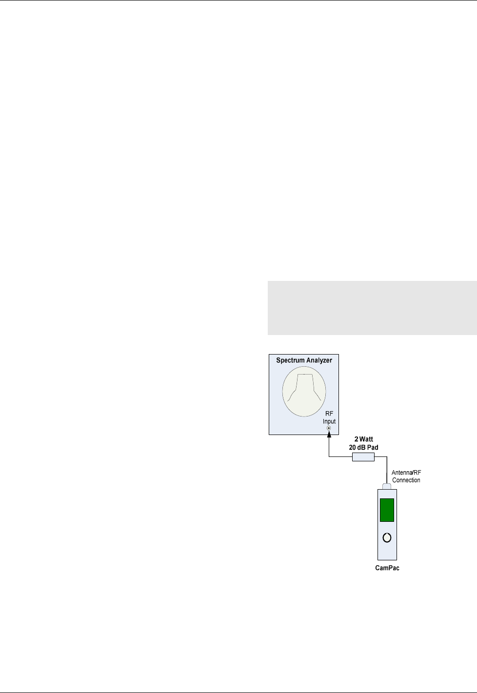
4.2 PRE-INSTALLATION CHECK
Connect the CamPac2 output through a 2-
watt, 20-dB attenuator to a spectrum analyzer
to observe the output frequency on the
analyzer display. After connecting a suitable
power source to the unit, turn the unit on. Set
the spectrum analyzer frequency to the
frequency of the channel being observed on
the CamPac2.
4.3 MECHANICAL INSTALLATION
The CamPac2 comes standard with an Anton
Bauer Mounting Bracket Assembly. This
allows the CamPac2 and battery to be quickly
attached or removed from a portable video
camera. This design is ideal for field use.
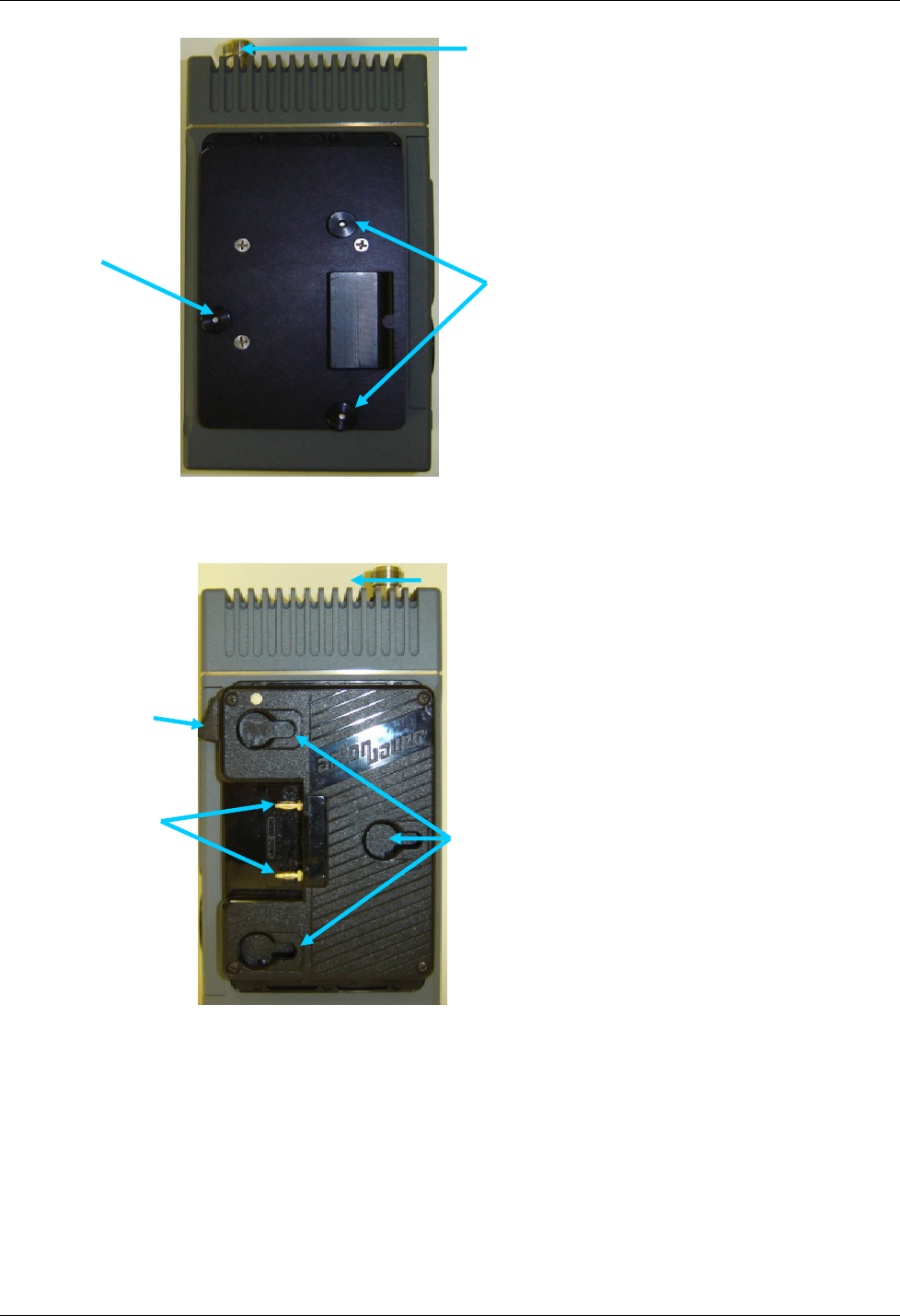
Mounting the Camera
To mount the CamPac2 unit to a camera, do
the following:
1. Orient the CamPac2 Guide Pins (Figure 2
and 3) so that the antenna connector is
positioned to the top of the CamPac2.
2. Next, place the CamPac2 Guide Pins into
the corresponding camera mounting slots.
(See Figure 2).
3. Slide the CamPac2 onto the mounting
bracket until you hear the thumb-catch
lock. Ensure that there is no play between
the CamPac2 and the camera.
4. Screw the antenna onto the CamPac2.
Ensure that the antenna is secure.
5. Orient the Battery Guide Pins to the
CamPac2.
6. Slide the battery onto the CamPac2 until
you hear the thumb-lock catch. Ensure that
there is no play between the battery and the
CamPac2, (See Figure 3).
7. Connect the desired camera outputs to the
CamPac2.
NOTE: When setting up the CamPac2,
ensure that the Main Menu
selections match the physical
connections.
Figure 1: System Check
CamPac2 Installation
M13-0003-00A 20
Figure 2: Camera Guide Pins
Figure 3: Battery Guide Slots
Antenna Connector
Camera Mount
Guide Pins
Camera Mount
Guide Pin
Antenna Connector
Release Lever
Battery Mount
Guide Slots
Banana
Pins
CamPac2 Installation
M13-0003-00A 21
4.4 CONNECTIONS
Video:
The video inputs to the CamPac2 are either
through the 12 pin LEMO connector or a 75-
Ohm coaxial cable with BNC connectors (See
Figure 6). Connect the video source to the
appropriate video input:
HD/SD-SDI – For Serial Digital Interface.
ASI or Composite, Analog Component.
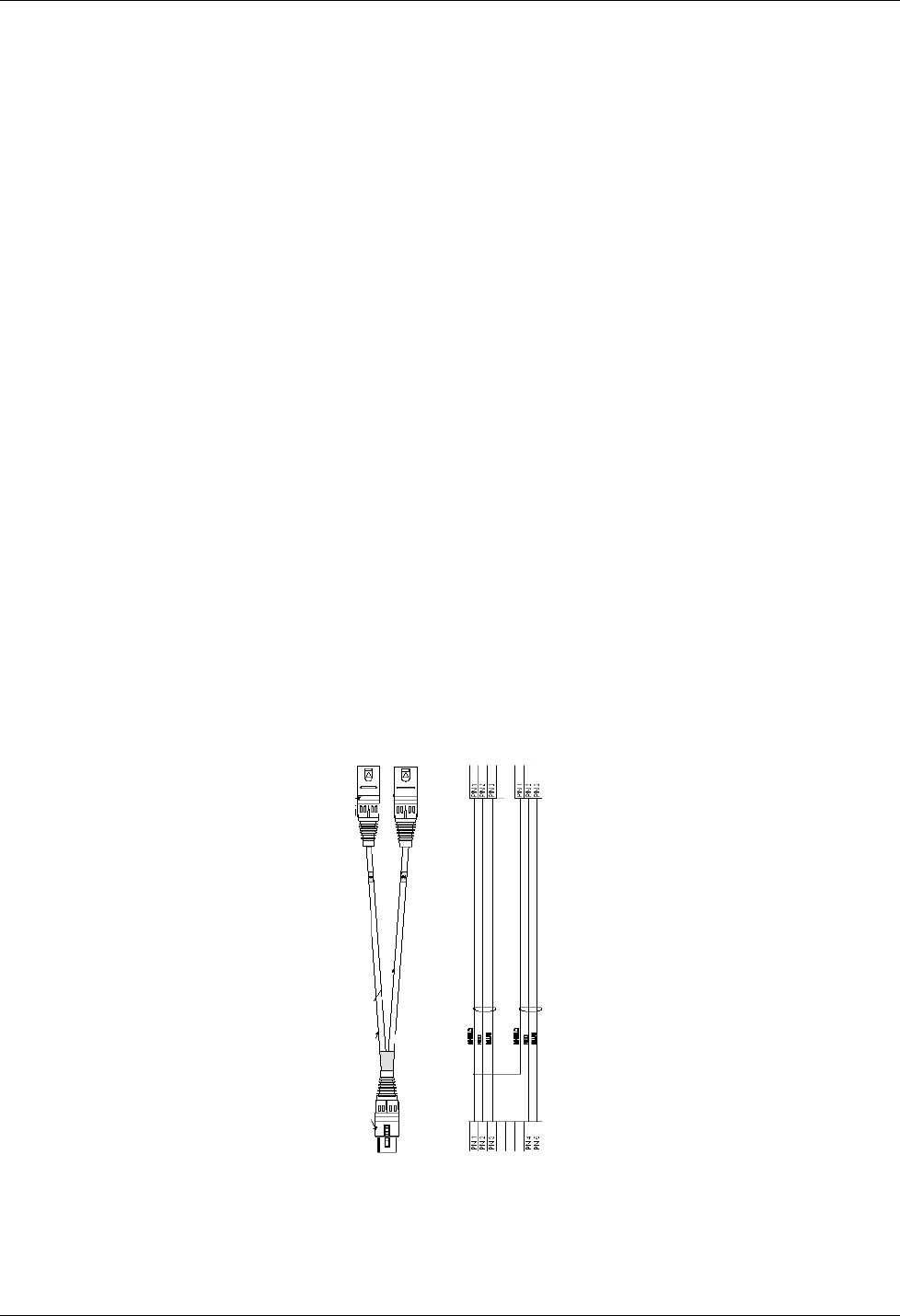
Audio:
The CamPac2 supports three audio types,
which are connected similarly. Analog and
AES audio connections to the CamPac2 are
through the two 5-pin XLR audio connections
(Figure 9) directly next to the video
connections. They are:
5 Pin XLR Audio 1 connector - Channel 1/
Channel 2 = MIC or line level.
5 Pin XLR Audio 2 connector - Channel 3/
Channel 4 = line level or AES
Embedded digital audio is input through the
BNC connector. This requires that whenever
Embedded is selected as the audio source, SDI
must be selected as the video source.
Power:
The CamPac2 normally receives power from
an external “clip-on” battery. In addition,
there is an alternate power input port available
on the bottom panel of the CamPac2 via a 4-
pin XLR external power connection (Figure
9).
Remote:
A micro USB Remote connector is provided
next to the bottom plate. This is used to
interface between the CamPac2 and a PC or a
PDA.
Figure 4: 5 Pin Female XLR to Two 3 Pin Male XLR
CamPac2
M13-0003-00A
Figure
Pin 1: Component Y
GND (ground)
Pin 2: Component Y
signal
Pin 3:
Component Pb GND (ground)
Pin 4: Component Pb
Pin 5:
Component Pr GND (ground)
Pin 6: Component Pr
Pin 7:
User Data RS422+
Pin 8:
User Data RS422
Pin 9: IF GND
(ground)
Pin 10:
IF Out (IF Base Units Only)
Pin 11:
ASI GND
(ground)
Pin 12:
ASI output
Table 2:
12 pin LEMO Connector Pin
Pin #1
Pin #2
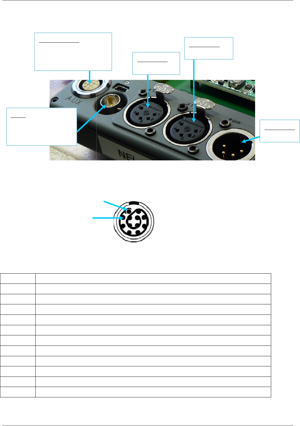
12 Pin LEMO
Component (Y Pr Pb)
ASI Out
User Data (IF Out)
BNC
HD/SD SDI In,
Composite In,
ASI In
22
Figure 5: Rear Panel
Figure
6: 12 pin LEMO Connector Pin-Out
GND (ground)
signal
Component Pb GND (ground)
Component Pr GND (ground)
User Data RS422+
User Data RS422
-
(ground)
IF Out (IF Base Units Only)
(ground)
12 pin LEMO Connector Pin
-Out (p/n
FGG.2B.312.CLAD62
Pin #1
Component (Y Pr Pb)
5 pin XLR
Audio Ch 1-2
5 pin XLR
Audio Ch 3-
4
Installation
FGG.2B.312.CLAD62
)
4 pin XLR
Power In

CamPac2
M13-0003-00A
Figure
1:
Audio Ground
2:
Audio 1 (Left)
3:
Audio 1 (Left)
4:
Audio 2 (Right)
5:
Audio 2 (Right)
Table 3:
5 pin XLR
Figure
DC Power Out
1:
GND
2 NC
3 NC
4 +12VDC to 28VDC
Pin #1
23
Figure
7: 5 Pin-XLR Connector Pin-Out
+/Hot
-/Cold
+/Hot
-/Cold
5 pin XLR
Connector Pin -
Out (p/n FGG.1B.305.CLAD52)
Figure
8: 4 Pin XLR Power Connector Pin-Out
Table 4: DC 4 pin Connector Pin –Out
Pin #1
Pin #1
Installation
Out (p/n FGG.1B.305.CLAD52)

CamPac2 Installation
M13-0003-00A 24
CamPac2 Operation
M13-0003-00A 25
5. OPERATION
5.1 POWER UP
The CamPac2 is turned on by connecting the
unit to the battery. The unit will boot-up and
go through a self-check mode for several
seconds until the system displays the Default
Screen.
RF Off/On (Standby):
Transmissions can be powered On and/or
Off without disconnecting the battery
and shutting off the entire unit, by
selecting the RF ON/OFF option from
the Default menu and toggling the power
on and/or off.
5.2 DEFAULT SCREEN
Once the unit has initialized, a Default Screen
resembling the following, is displayed:
TX ON
Ch
7
2101.50
Tone
VidTest
NTSC
16 Mb
1 2 3 4
14.7 V
39 C
Figure 9: Default Screen
The Default Screen displays the following
information:
Channel
Frequency
Power Capability
Data Rata MB
Battery Voltage
1 - 4 bars of Transmit Signal Strength
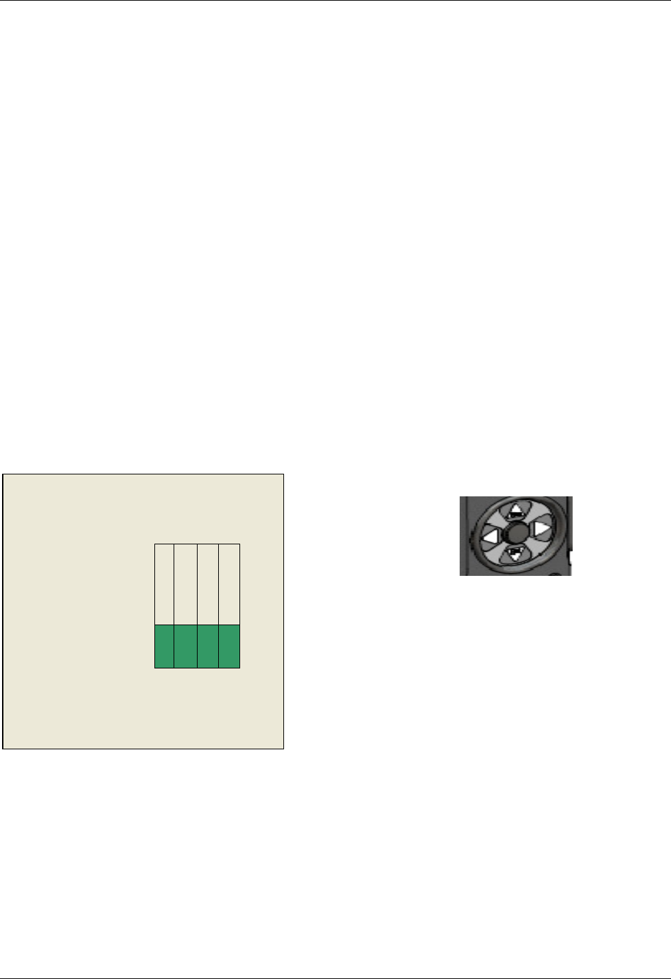
5.3 GETTING AROUND THE SYSTEM
Menu Navigation
Sensor Wheel/Rotary Dial:
All the CamPac2 operations and functions
are controlled by the Rotary Dial/Sensor
Wheel located on the bottom of the front
panel is used to set, change, update,
input and check different values, rates,
options and functionalities throughout
the system.
The Rotary Dial allows you to set values
higher and lower by circling the dial
with your finger, clock-or-counter-
clockwise. It is also used to move from
field to field in some cases depending on
where you are in the system.
After powering up the CamPac2 unit and
getting to the Default screen, press the
Enter ▼ (Ent) directional arrow button,
located on the Rotary Dial to get to other
screens within the system.
Figure 10: Rotary Dial
To Go to Previous Screen or Default, press
the Escape▲ (Esc) directional arrow on
the Rotary Dial to go to the previous
screen, and/or back to Default.
Menu Timeout:
LCD menu displays will stay on the screen
depending on the time limit set from the
Menu Timeout. The time limit ranges
from None (will never revert to default
screen) to 30 seconds.

CamPac2 Operation
M13-0003-00A 26
Changing Settings:
To change, view, input, select or update
settings, values, rates, levels or options
throughout most of the system, do the
following
1. Select the desired menu or option by using
the Rotary Dial and ENT button to reach
the desired screen.
Note: See the CamPac2 Menu Tree
diagram at the end of this document
for placement and location of all
options.
2. Press ▼ (Ent) to view that menu’s options.
4. Continue to press ▼ (Ent), and drill down
the menus until the value fields that need to
be changed are displayed.
5. Click on the Value field until it becomes
Active, (turns green).
6. Press the rotary dial, clockwise or counter-
clockwise to select value fields up or down
respectively –or- use the rotary dial to
scroll up or down an options list to your
choice with an *asterisk.
The settings have been saved to the system.
Note: If you are not choosing from an
options list, then you will be setting
the value from circulating the
rotary wheel. These value fields
need to be pressed until they turn
green and become “active”, before
they can be manipulated and data
can be changed. When you reach
the correct value, press [Enter] to
save.
5.4 TOP MENU
The Top Menu is reached by pressing ENT at
the DEFAULT screen, once the unit is booted.
Figure 11: Top Menu
5.6 MAIN MENU
Figure 12: Main Menu
5.7 RF SETUP
(MAIN>RF SETUP)
Figure 13: RF Setup Menu
RF Setup
Modulation
Video Setup
Audio Setup
Edit Presets
System
Alarms
Frequency
Bandwidth
TX Power
MAIN MENU
PRESETS
PWR ON
RF OFF
LOCK

CamPac2 Operation
M13-0003-00A 27
5.7.1 Frequency Menu
(MAIN>RF SETUP>FREQUENCY)
Figure 14: Frequency Menu
Note: About Frequency Direct, if Frequency
Direct Mode is enabled, the frequency
may be changed without limitation to
channels. Move the Rotary Dial to
highlight the frequency, and circulate
the Rotary Dial until you reach the
correct value(s). Press ▼ (Ent) to
register changes within the system.
5.7.2 Bandwidth
(MAIN>RF SETUP>BANDWIDTH)
Figure 15: Bandwidth and Filter
5.7.3 TX Power
(MAIN>RF SETUP>TX POWER)
IF the TXPwr Auto OFF option has been
selected (from the Power Control menu),
the screen with a variable flexible rate (0
through to 51 on most units) will be
displayed.
IF the TXPwr Auto ON option has been
selected (from the Power Control menu),
the TX Power screen with the fixed Power
Control settings will be displayed; 25mW,
100mW.
Figure 16: TX Power screen
IMPORTANT:
The TX Power value field will display a
Variable setting that can be adjusted from
0-51 if Power Control TXPwr Auto OFF
is selected. If TX Pwr Auto ON is
selected, then use the rotary dial to choose
one of the standard settings:
25mW
100mW
(the standard settings are recommended)
5.7.3.1 How to set the TX Power Settings:
The following procedure instructs the user
how to set the TX Power Setting from
beginning to end. To set the CamPac2 TX
Power Output settings, do the following:
1. Power up the Campac2 unit.
2. From the Default screen, click ▼(Ent).
The Top screen is displayed.
3. Press ▼ (Ent). The Main Menu is
displayed.
4. Use the rotary dial to select the System
option and press ▼(Ent).
5. Using the rotary dial, select the Power
Control option and press ▼(Ent).The
Power Control option list is displayed.
6. Toggle to the correct option and press ▼
(Ent). Your option has been registered and
the screen will automatically shut off and
start up on its, own, regardless of the option
choice.
Frequency
1999.000
Channel
1
Band
2.0 GHz
Bandwidth
8 MHz
Filter
On/Off
TX Power
1 (0
-
51)
or
(25mW
,
100
mW
)

CamPac2 Operation
M13-0003-00A 28
Choose your Settings
7. After the Campac2 unit powers back on, the
Default screen is displayed.
8. Press ▼(Ent) to bring up the Top Menu
and press the RF Setup option from that
menu. The RF Setup menu is displayed.
9. Scroll down to the TX Power option and
press ▼(Ent). The TX Power screen is
displayed. The field will display either the
Fixed Settings –or – the Standard Fixed
Settings depending on what was chosen
under the System►Power Control option.
10 Press ▼ (Ent) on the Number Field until it
becomes active (turns green) and use the
rotary dial to scroll around the dial and
make your number selection. Press ▼ (Ent)
when you found the correct value.
5.8 MODULATION
(MAIN>MODULATION)
Figure 17: Modulation Options
5.8.1 Constellation
(MAIN>MODLATION>CONSTELLATION)
QPSK
16QAM
64QAM
5.8.2 Code Rate
(MAIN>MODULATION>CODE RATE)
1/2
2/3
3/4
5/6
7/8
5.8.3 Guard Interval
(MAIN>MODULATION>GUARD INTERV)
1/32
1/16
1/8
1/4
5.9 VIDEO SETUP
(MAIN>VIDEO)
Figure 18: Video Setup Options
5.9.1 Input
(MAIN>VIDEO>INPUT)
Figure 19: Video Input Options
5.9.2 Format
(MAIN>VIDEO>FORMAT)
Figure 20: Video Format Options
Constellation
Code Rate
Guard Interval
Input
Format
Test Modes
Options
HDSDI / SDI
Composite
Y Pr Pb
S-Video
Test Modes
Ext ASI (BNC)
Format
NTSC
Frame Rate
29.97 Hz
Chroma
4:2:0

CamPac2 Operation
M13-0003-00A 29
5.9.3 Test Modes
(MAIN>VIDEO>TEST MODES)
Figure 21: Test Modes Options
5.9.4 Options (Video)
(MAIN>VIDEO>OPTIONS)
Figure 22: Video Options List
5.9.4.1 I/P GOP
(MAIN>VIDEO>OPTIONS>I/P GOP)
I Frames only
IP GOP 15
IP GOP 10
IP GOP 6
IP GOP 5
5.9.4.2 Delay
(MAIN>VIDEO>OPTIONS>DELAY)
Normal Delay
Low Delay
Lowest Delay
5.9.4.3 Pedestal
(MAIN>VIDEO>OPTIONS>PEDESTAL)
On
Off
5.9.4.4 ASI Out Sel
(MAIN>VIDEO>OPTIONS>ASI Out Sel)
Modulator
Encoder
5.9.4.5 Video Loss
(MAIN>VIDEO>OPTIONS>Video Loss)
No Change
Go To Bars
The selection is registered to the system
and marked with an *asterisk.
5.9.4.6 PTS Edit
(MAIN>VIDEO>OPTIONS>PTS Edit)
Figure 23: PTS Screen
5.9.4.7 PID Edit
(MAIN>VIDEO>OPTIONS>PID Edit)
Figure 24: PID Edit Screen
Test Off
SMPTE Bars
Zone Plate
Lip Sync
I/P GOP
Delay
Pedestal
ASI Out Sel
Video Loss
PTS Edit
PID Edit
Vid PID
0x0031
Aud0 PID 0x0034
Aud1 PID 0x0035
Aud1 PID 0x0035
Pmt PID 0x003f
PCR PID 0x0134
PTS Selection
Manual
Video PTS
9970
Audio PTS
9870

CamPac2 Operation
M13-0003-00A 30
5.10 AUDIO SETUP
(MAIN>AUDIO)
Figure 25: AUDIO Setup
5.10.1 Inputs
(MAIN>AUDIO>INPUTS)
Figure 26: Audio Inputs List
5.10.2 Audio Level dB
(MAIN>AUDIO>Audio Level dB)
Figure 27: Audio Level dB
5.11 PRESETS
5.11.1 Storing Presets
(MAIN>EDIT PRESETS>PRESET 1-4)
1. Make your preferred settings.
2. From the MAIN Menu, select Edit Presets.
Figure 28: Presets Options
3. Select the Preset to be saved, press ▼(Ent).
Figure 29: Preset Menu Options
4. Select Store, then press ▼ (Ent) to save
your new preset to the system.
The Store screen is displayed, and reads:
[Preset Stored].
5.11.2 Naming (Labeling) Presets
(MAIN>EDIT PRESETS>PRESET 1-4)
1. Using the rotary dial, scroll to the Name
option and press ▼(Ent).
The Preset name (originally 1 through 4)
appears on the screen.
2. Press ▼ (Ent) to activate the Preset name
field (it will turn green).
The cursor appears on the first alpha-
numeric character of the current name.
3. Press the rotary dial, clock –or-counter-
clockwise to change the first character in
the new label.
4. When you have reached the desired value
(number or letter), press ▼ (Ent) –or-
► on the rotary dial to go to the next
character in your label. Use the ◄
directional arrow on the rotary dial to
backup if needed.
5. Repeat the procedure for the rest of the
characters on this preset until the title has
been created.
6. Press ▼ (Ent) and ▲(Esc) to register your
label in the system.
The label is displayed on the screen.
Inputs
Audio Level dB
Mic/Lines
Mic/AES
AES/AES
Embedded SDI
Tone
Beep
Tone & Beep
CH1: +0
CH2: +0
CH3: +0
CH4: + 0
PRESETS 1
PRESETS 2
PRESETS 3
PRESETS 4
Recall
Store
Name

CamPac2 Operation
M13-0003-00A 31
5.11.3 Recalling Presets
(MAIN>EDIT PRESETS>PRESET 1-4)
1. Using the rotary dial, scroll to the Recall
option and press ▼(Ent). The Preset
name (originally 1 through 4) appears on
the screen.
2. Press ▼(Ent) to recall the preset and
return to the Default screen.
5.12 SYSTEM
(MAIN>SYSTEM)
Figure 30: System Setup
5.12.1 Menu Timeout
(MAIN>SYSTEM>Menu Timeout)
None
10 Seconds
20 Seconds
30 Seconds
The selection is marked by an *asterisk.
5.12.2 LCD Brightness
(MAIN>SYSTEM>LCD Brightness)
Day mode
Night mode
The selection is marked by an *asterisk.
5.12.3 RF Enable
(MAIN>SYSTEM>RF Enable)
Disable
Enable
5.12.4 Power Control
(MAIN>SYSTEM>Power Control)
5.12.5 Factory Default
(MAIN>SYSTEM>Factory Default)
Allows the user to restore factory defaults.
WARNING: Any user settings will be over-
written.
No – resume ops
Yes – defaults
5.12.6 TX Name
(MAIN>SYSTEM>TX Name)
The default transmitter name is
“CAMPAC2”. To change the TX Name:
1. MAIN>SYSTEM>TX Name
The current TX Name is displayed:
[CAMPAC 2 ]
2. Click ▼ (Ent) to activate the “name” field.
(Field turns green when ready for input).
The cursor appears on the first character.
3. Use the rotary dial to scroll alpha-numeric
characters, press ▼ (Ent) to select.
4. Use the ◄►arrows to select the next
character, repeat until the name is updated.
5. Press ▼ (Ent) to save it to the system.
Menu Timeout
LCD Brightness
RF Enable
Power Control
Factory Default
TX Name
SW Version
Security Key

CamPac2 Operation
M13-0003-00A 32
5.12.7 SW Version
(MAIN>SYSTEM>SW Version)
Displays version numbers of the unit’s Side
Panel, Baseband, Up Converter, and FPGA.
5.12.7 Security Key
(MAIN>SYSTEM>Security Key)
To set the system’s security key code (for
HD/SD Enable/Disable), do the following:
1. To activate the screen, click ▼ (Ent).
The field becomes active (turns green).
2. Using the rotary dial, set the correct code by
scrolling the alpha-numeric characters until
you reach the desired setting.
3. Use the ◄►arrows to move on to the next
character of the Security Key code until the
code has been set.
5. Press ▼ (Ent) to save the changes.
5.13 ALARMS
(MAIN>ALARMS)
This screen can provide information
regarding some system errors if they
should occur, and indicates the reason
for any alarms.
1. To activate the screen, click ▼ (Ent). The
field becomes active (turns green).
2. The Alarms indication list is displayed. If
there were no Alarms indicated, there will be
no alarms displayed on the screen.
5.14 POWER ON/RF OFF (Standby)
(TOP>PWR ON)
Allows the user to toggle the CamPac2
transmitter on and off (standby).
Note: Depending on whether or not the unit
is transmitting or on standby, POWER
ON or RF OFF will be displayed, and a
TX ON or RF SBY indicator will be
displayed on the screen’s upper right
hand corner.
5.15 SLEEP/RF OFF
(TOP>RF OFF)
To set the CamPac2 unit to SLEEP mode,
or to set it to RF OFF mode if already in
sleep mode, use the rotary dial to scroll
down to the SLEEP –or-RF OFF
option.
Note: Depending on whether or not the unit
is transmitting or on standby, the SLEEP
or RF OFF indicator will be displayed
on the screen’s upper right hand corner.
5.16 LOCK
(TOP>LOCK)
To lock the Campac2 unit so that settings
remain “on hold” until you are ready to
begin using it again:
1. Scroll down to the “Lock” option and
press ▼ (Ent).
2. Hold the ▼ (Ent) button to lock the
unit. The screen displays the message:
[HOLD BUTTON TO UNLOCK].
3. When you are ready to unlock the unit,
hold down the ▼ (Ent) button until the
“Top” First Menu re-appears.
4. The system is unlocked. The settings
are the same as when the system was
locked.

CamPac2 Operation
M13-0003-00A 33
5.17 SETTING DATA RATE
The following tables are to be used in setting up the Data Rate. The Data Rate is based onBandwidth,
Type of Modulation, Code Rate, and Guard Interval.
Modulation
System
Code Rate
Guard Interval
1/32 1/16 1/8 1/4
Bandwidth = 6 MHz
Data Rate (Mbit/s)
QPSK
1/2 4.5240645 4.48248248
4.2334561 3.81011061
2/3 6.03208575
5.854671 5.5294118 4.9764705
3/4 6.786096 6.58650525
6.2205885 5.5985295
5/6 7.540107 7.31833875
6.9117645 6.2205885
7/8 7.9171125 7.68425625
7.2573533 6.531618
16QAM
1/2 9.048129 8.7820065 8.294118 7.4647065
2/3 12.0641715
11.709342 11.058824 9.952941
3/4 13.572192 13.1730105
12.441177 11.197059
5/6 15.080214 14.6366775
13.823529 12.441177
7/8 15.834225 15.3685125
14.514707 13.063236
64QAM
1/2 13.5721935
13.1730098
12.441177 11.1970598
2/3 18.0962573
17.564013 16.588235 14.9294115
3/4 20.358288 19.7595158
18.661766 16.7955885
5/6 22.620321 21.9550163
20.735294 18.6617655
7/8 23.7513375
23.0527688
21.77206 19.594854
Table 2: Data Rates for 6 MHz Bandwidth
Modulation
System
Code Rate
Guard Interval
1/32 1/16 1/8 1/4
Bandwidth = 7 MHz
Data Rate (Mbit/s)
QPSK
1/2 5.27807525 5.12283713 4.8382355 4.35441213
2/3 7.037433375 6.8304495 6.45098038 5.80588225
3/4 7.917112 7.68425613 7.25735325 6.53161775
5/6 8.7967915 8.53806188 8.06372525 6.2205885
7/8 9.23663125 8.96496563 8.46691213 7.620221
16QAM
1/2 10.5561505 10.2456743 8.294118 8.70882425
2/3 14.07486675 13.660899 9.676471 11.6117645
3/4 15.834224 15.3685123 12.9019608 13.0632355
5/6 17.593583 17.0761238 16.1274505 12.441177
7/8 18.4732625 17.9299313 16.9338243 15.240442
64QAM
1/2 15.83422575 15.3685114 14.5147065 13.0632364
2/3 21.11230013 20.4913485 19.3529411 17.4176468
3/4 23.751336 23.0527684 21.7720598 19.5948533
5/6 26.3903745 25.6141856 24.1911758 21.7720598
7/8 27.70989375 26.8948969 25.4007364 22.860663
Table 3: Data Rates for 7 MHz Bandwidth

CamPac2 Operation
M13-0003-00A 34
Modulation
System
Code Rate Guard Interval
1/32 1/16 1/8 1/4
Bandwidth = 8 MHz
Data Rate (Mbit/s)
QPSK
1/2 6.032086 5.854671 5.529412 4.976471
2/3 8.042781 7.806228 7.372549 6.65294
3/4 9.048128 8.782007 8.294118 7.464706
5/6 10.053476 9.757785 9.215686 8.294118
7/8 10.55615 10.245675 9.676471 8.708824
16QAM
1/2 12.064172 11.709342 11.058824 9.952942
2/3 16.085562 15.612456 9.676471 11.6117645
3/4 18.096256 17.564014 16.588236 14.929412
5/6 20.106952 19.51557 18.431372 16.588236
7/8 21.1123 20.49135 19.352942 17.417648
64QAM
1/2 18.096258 17.564013 16.588236 14.929413
2/3 24.128343 23.418684 22.117647 19.905882
3/4 27.144384 26.346021 24.882354 22.394118
5/6 30.160428 29.273355 27.647058 24.882354
7/8 31.66845 30.737025 29.029413 26.126472
Table 4: Data Rates for 8 MHz Bandwidth
Table 5: Data Rates for 16 MHz Bandwidth
Modulation
System
Code Rate Guard Interval
1/32 1/16 1/8 1/4
Bandwidth = 16 MHz
Data Rate (Mbit/s)
QPSK
1/2 12.064172 11.709342 11.058824 9.952942
2/3 16.085562 15.612456 14.745098 13.270588
3/4 18.096256 17.564014 16.588236 14.929412
5/6 20.106952 19.51557 18.431372 16.588236
7/8 21.1123 20.49135 19.352942 17.417648
16QAM
1/2 24.128344 23.418684 22.117648 19.905884
2/3 32.171124 31.224912 29.490196 26.541176
3/4 36.192512 35.128028 33.176472 29.858824
5/6 40.213904 39.03114 36.882774 33.176472
7/8 42.2246 40.9827 38.705884 34.835296
64QAM
1/2 39.192516 35.128026 33.176472 29.858826
2/3 48.256686 46.837368 44.235294 39.811764
3/4 54.288766 52.692042 49.764708 44.788236
5/6 60.320856 58.54671 55.294116 49.764708
7/8 63.3369 61.47405 58.058826 52.252944

CamPac2 Operation
M13-0003-00A 35
Modulation
System
Code Rate Guard Interval
1/32 1/16 1/8 1/4
Bandwidth = 20 MHz
Data Rate (Mbit/s)
QPSK
1/2 15.080215 14.6366775 11.058824 9.952942
2/3 20.1069525 19.51557 14.745098 13.270588
3/4 22.62032 21.9550175 16.588236 14.929412
5/6 25.13369 24.3944625 18.431372 16.588236
7/8 26.390375 25.6141875 19.352942 17.417648
16QAM
1/2 30.16043 29.273355
2/3 40.213905 39.03114 29.490196 26.541176
3/4 45.24064 43.910035 33.176472 29.858824
5/6 50.26738 48.788925 36.882774 33.176472
7/8 52.78075 51.228375 38.705884 34.835296
64QAM
1/2 45.240645 43.9100325 33.176472 29.858826
2/3 60.3208575 58.54671 44.235294 39.811764
3/4 67.86096 65.8650525 49.764708 44.788236
5/6 75.40107 73.1833875 55.294116 49.764708
7/8 79.171125 76.8425625 58.058826 52.252944
Table 6: Data Rates for 20 MHz Bandwidth
CamPac2 Operation
M13-0003-00A 36
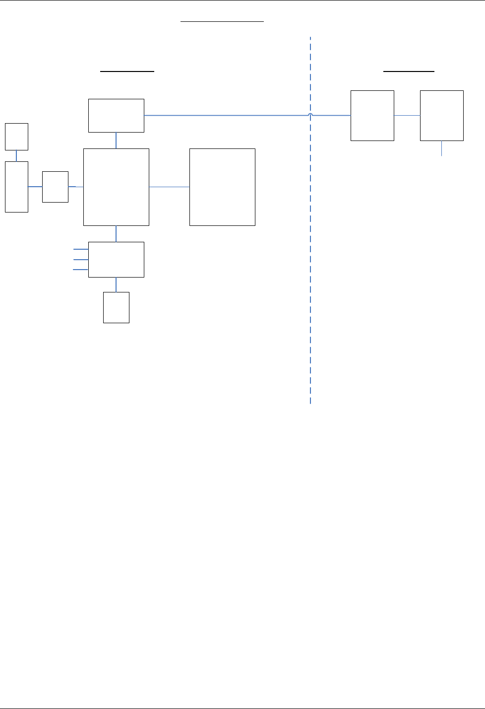
Upconverter
Baseband
Intface
836.5 MHz to
2 GHz
Upconverter
HDTX
Ctrlr.
Wheel
Panel
Interface
USB
intf.
Encoder
Video
Audio
Power
Power
Amp
RF Out
IF Base Unit IF RF Head
CAMPAC2 - IF
Functional Block Diagram
JJD
03/20/08
Figure 31: Block Diagram of the CP2 IF Cameraback Transmitter
CamPac2 Operation
M13-0003-00A 37
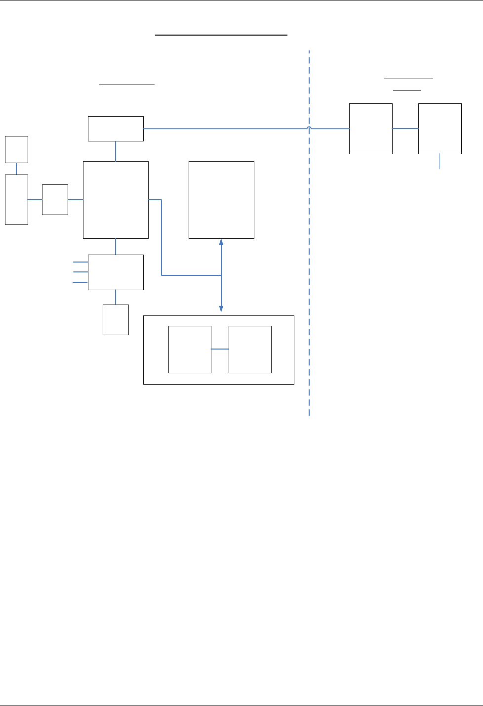
IQ Interface
Baseband
Intface
IQ Modulator
Up-converter
HDTX
Ctrlr.
Wheel
Panel
Interface
USB
intf.
News EncoderEncoder
Interface
Pro Encoder
OR
PRO VERSION
Video
Audio
Power
Power Amp
RF Out
IQ Base Unit IQ RF Head
(PAM)
CAMPAC2 PRO/NEWS
Functional Block Diagram
JJD
03/20/08
NEWS VERSION
Interchangeable for
different frequency
bands
Figure 32: Block Diagram of the CP2 Pro/News Cameraback Transmitter

CamPac2 Menu Tree
M13-0003-00A 38
Terms & Definitions
16QAM (16 phase Quadrature Amplitude Modulation) A digital modulation
technique that combines amplitude modulation and phase shift
keying (16-phase-states) in sending data. This type of modulation
supports a transfer rate up to 14 Mbps.
64QAM (64 phase Quadrature Amplitude Modulation) A digital modulation
technique that combines amplitude modulation and phase shift
keying (64-phase-states) in sending data. This type of modulation
supports a transfer rate up to 28 Mbps.
AES/EBU (Audio Engineering Society/European Broadcasting Union) is an
older standard developed for transferal of digital audio signals. The
AES/EBU specifies a single cable in carrying audio data for both
digital left- and right-channels to a receiving device. Normally, a 3
pin XLR cable is used.
Composite Video A single analog video signal encoded with luminance (brightness),
chrominance (color), horizontal, and vertical synchronization
information, is preset within the signal.
COFDM (Coded Orthogonal Frequency Division Multiplexing) A type of
modulation scheme where more than a 1000 signals are generated
from a single signal, and transmitted at right angles to each other.
This is to reduce signal loss by a receiver due to obstructions and
reflections.
DVB-T (Digital Video Broadcasting -Terrestrial) An international digital
broadcast standard developed in Europe. DVB-T specifies a
bandwidth of 6 to 8 MHz per channel, while utilizing MPEG-2 video
compression and MPEG audio compression.
EIRP Effective Isotropic Radiated Power.
FEC (Forward Error Correction) A transmission technique that utilizes
error correction data being sent with the carrier signal for possible
signal re-generation by the receiver should errors be detected.
GOP (Group Of Pictures) A sequence of frames within an MPEG-2
stream to allow video editing and splicing from different signal
sources.
IDX Anton-Bauer Battery Clip

CamPac2 Menu Tree
M13-0003-00A 39
MPEG (Moving Picture Expert Group) A family of standards that utilizes
complex compression techniques to encode audio-video information
into a signal.
NTSC (National Television Systems Committee) A United States based
organization, which develops technical standards for broadcasting.
PAL (Phase Alternating Line) The European standard for video
broadcast.
PAM Removable, frequency determining module called the RF Power
Amplifier Module of the CamPac2.
PID (Package Identifier) Information located at the beginning of a
transmitted packet that tells the receiver what to do with the packet.
QPSK (Quadrature Phase Shift Keying) A digital frequency modulation
technique where a single phase carrier is modulated into a four
phase signal, with each quadrant represented by a two digit binary
number. The signal is then transmitted and demodulated by the
receiver into frequency independent voltage levels.
SDI (Serial Digital Interface) A digital video format utilizing a 270 Mbps
(for Standard Definition) or 1.5Gbps (for High Definition) data rate.
The signal consists of a 10-bit, serial interface for both digital video
and four channels of embedded digital audio. SDI requires a
standard 75-ohm BNC connector and coax cable for connection to a
device.
Symbol A single Symbol can be considered one phase-state of a QPSK
signal. All four Symbols used together can be considered the baud
rate of the signal.
Transport Stream When several video and analog inputs are multiplexed into a single
data stream for transmission.
CamPac2 Menu Tree
M13-0003-00A 40
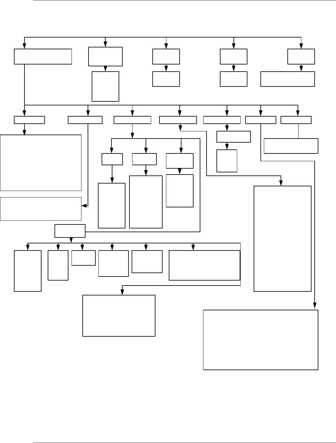
5.18 MENU TREE
Figure 33: Menu Tree
LOCK
RF OFF/
RF ON
PRESETSMAIN MENU/TOP MENU SLEEP/
PWR ON
HOLD BUTTON TO
UNLOCK
DEFAULT
SCREEN
PRESET 1
PRESET 2
PRESET 3
PRESET 4
DEFAULT
SCREEN
Modulation Video SetupRF Setup Audio Setup Edit Presets System Alarms
Frequency: Frequency [Freq Range]
Channel: [Channel range]
Band: [Band GHz range]
Bandwidth: Bandwidth [MHz Range]
Filter: (On/Off)
TX Power: TX Power [TX power range]
Constellation: (QPSK, 16QAM, 64QAM)
Code Rate: 1/2, 2/3,3/4, 5/6, 7/8)
Guard Interval: (1/32, 1/16, 1/8,1/4)
(Test Off,
SMPTE
Bars, Zone
Plate Lip
Sync)
IP/GOP:
(I Frames
only, IP
GOP 15, IP
GOP 10, IP
GOP 6, IP
GOP 5)
(NTSC, PAL,
480P, 576P,
720P, 1080i,
1080PsF)
Frame Rate:
(Rate)
Chroma:
(4:2:0-4:2:2)
Presets 1-4
Recall
Store
Name
Menu Timeout: (None, 10, 20, 30 Seconds).
LCD Brightness: (Day mode, Night mode).
RF Enable: (Disable, Enable).
Power Control: (TXPwr Auto OFF, TXPwr Auto ON).
Factory Default: (No-resume ops, Yes-defaults).
Telemetry: (Enable, Disable).
TX Name: (CAMPAC2 -Label).
SW Version: (Sidepanel, Baseband, UpConverter, FPGA).
Security Key: (Serial Number, Enter Key, HD Licensed).
Lists any alarm indications
(HD/SDI,
Composite,
Y Pr Pb,
S-Video,
Test Modes
Ext ASI
(BNC)
INPUT FORMAT TEST
MODES
Options
Delay:
Normal
Low
Lowest
Delay
Pedestal:
On/Off ASI Out Sel:
Modulator
Encoder
Video Loss:
No Change
Go to Bars
PTS Edit:
PTS Selection (Manual/Automatic)
Video PTS [Range]
Audio PTS (Range)
PID Edit:
Vid PID 0x0031 (Set to Range)
Aud0 PID 0x0034 (Set to Range)
Aud1 PID 0x0035 (Set to Range)
PMT PID 0x003f (Set to Range)
PCR PID 0x0134 (Set to Range)
Inputs: (Mic/Line, Mic/AES,
AES/AES, Embedded SDI,
Tone, Beef, Tone & Beep).
Audio Level dB:
CH1: (Range)
CH2: (Range)
CH3: (Range)
CH4: (Range)
Limiter:
CH1: (On/Off)
CH2: (On./Off)
Gang (On/Off)
Phantom:
CH1: (On/Off)
CH2: (On/Off)

CamPac2
M13-0003-00A 41

CamPac2
M13-0003-00A 42
Integrated Microwave Technologies, LLC
101 Bilby Road
Hackettstown, NJ 07840
Tel: 908-852-3700 Fax: 908-813-0399
www.imt-solutions.com