Intel RCM24G Intel Radio Control Module 2.4 GHz User Manual User manual FCC ISED
Intel Corporation Intel Radio Control Module 2.4 GHz User manual FCC ISED
Intel >
Contents
- 1. User_manual_FCC_ISED
- 2. User Manual
User_manual_FCC_ISED

Page 1 of 5
Intel® Radio Control Module 2.4 GHz
Model: RCM24G
Manual (US/CAN)
Revision 1.0
Revision History
Revision
Description
Date
1.0
RCM24G Modular Approval
US/Canada
01.04.2017
Overview
The RCM24G is a data transceiving module for wireless communication between two or more nodes
of this kind.
Instruction
Do only use
- with specified antennas
- within specified supply voltage range
- interfacing via UART/CAN-Bus
Page 2 of 5
Specification:
Module output
(Frequencies)
70 Hopping channels from 2402.5 MHz (Channel 0) to 2471.5MHz
(Channel 69),
1MHz channel spacing, ADFSS
Modulation
MSK modulation
Receiver Bandwidth
232kHz, 540kHz, 812.5kHz
Datarate
50kbit/s, 100kbit/s, 250kbit/s and 500kbit/s
Dwell Time
10ms (500kbit/s) to 28ms (50kbit/s). Fixed amount of useable data per
hop (128 bytes TX and 128 byte RX)
CCA
Inactive
Supply Input range
3.6 VDCV ± 5% / 1A
Testing Antennas
1x Intel® FA5 antenna (HW-Version: Antenna-002) with 5 ports
1x Prestta WLAN Embedded Antenna P/N: 1000418 50 Ohm
unbalanced
Antenna connection
µUFL
Connector type: 50 Ohm nominal
Permissive antenna
type/gain
Type: (Circularly polarized) patch antenna
Max. antenna gain: 4.86 dBi
Type: Dipole
Max. antenna gain: 2.5 dBi
Antenna configuration
1 antenna/module
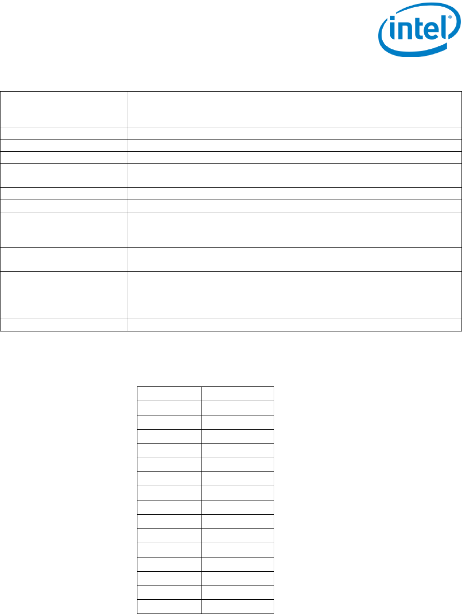
Transmitter Output Power
Channel
Max. power
0-3
10.19 dBm
4-7
10.72 dBm
8-10
12.84 dBm
11-14
14.71 dBm
15-17
16.37 dBm
18-21
17.92 dBm
22-24
19.05 dBm
25-39
19.93 dBm
40-43
18.81 dBm
44-48
17.79 dBm
49-52
16.19 Bm
53-57
14.51 dBm
58-61
12.49 dBm
62-66
10.36 dBm
67-69
9.32 dBm
Table 1 Max. Power Settings
Operational Characteristics
Hopping mode
A user serial number is used to generate a 70 hop long pseudo random hopping sequence which is
contains each channel exactly once and is repeated every 70 hops.
Page 3 of 5
Diversity Mode
The RCM24G module is designed to work in the following diversity mode: Two adjacent modules
transmit parallel with full power. The pseudo random hopping frequency along with dissimilar seeding
ensures that both modules never occupy the same channel at a time. CCA is not performed.
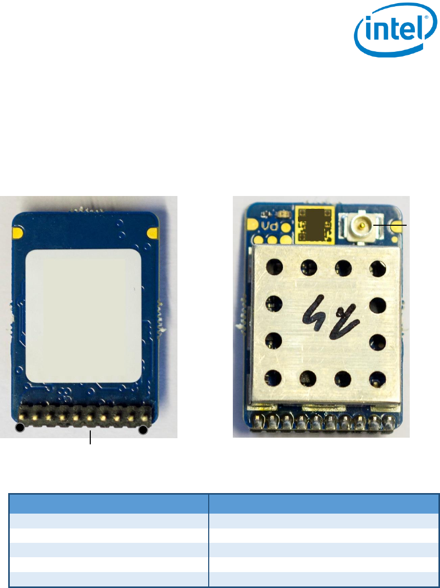
Connection
Figure 1 RCM24G Bottom View
Figure 2 RCM24G Top View
Pin
Signal
Designation
Pin
Signal
Designation
1
V_sup
3.3V
2
GND
GND
3
UART2
TX
4
UART2
RX
5
I/O
General I/O
6
I/O
General I/O
7
UART 3
TX
8
UART 3
RX
9
CAN
RX
10
CAN
TX
Table 2: Transmitter Host Connector
THC (Transmitter Host Connector)
antenna
1
10

Page 4 of 5
FCC and ISED Statement
This device complies with Part 15 of the FCC Rules and with Industry Canada’s licence-exempt RSSs.
Operation is subject to the following two conditions:
(1) this device may not cause harmful interference, and
(2) this device must accept any interference received, including interference that may cause
undesired operation.
Cet appareil est conforme aux CNR d'Industrie Canada applicables aux appareils radio
exempts de licence.
L'autorisation d’exploitation est soumise aux deux conditions suivantes:
(1) l'appareil ne doit pas produire de d’interférences radioélectriques, et
(2) l'appareil doit accepter toute interference radioélectrique subi, même si le brouillage est
susceptible d'en compromettre le bon fonctionnement.
This equipment has been tested and found to comply with the limits for a Class B digital device,
pursuant to part 15 of the FCC Rules. These limits are designed to provide reasonable protection
against harmful interference in a residential installation. This equipment generates, uses and can
radiate radio frequency energy and, if not in-stalled and used in accordance with the instructions, may
cause harmful interference to radio communications.
However, there is no guarantee that interference will not occur in a particular installation.
If this equipment does cause harmful interference to radio or television reception, which can be
determined by turning the equipment off and on, the user is encouraged to try to correct the
interference by one or more of the following measures:
• Reorient or relocate the receiving antenna
• Increase the separation between the equipment and receiver
• Connect the equipment into an outlet on a circuit different from that to which the receiver is
connected
• Consult the dealer or an experienced radio/TV technician for help.
ICES-003 Statement (Canada)
This digital apparatus does not exceed the Class
B limits for radio noise emissions from digital
apparatus set out in the interference-causing
equipment standard entitled “Digital Apparatus,”
ICES-003 of the Canadian Department of
Communications.
Cet appareil numérique respecte les limites
bruits radioélectriques applicables aux appareils
numériques de Classe B prescrites dans la
norme relatives aux interferences causée par du
matériel: “Appareils Numériques”, NMB-003
édictée par le Ministre Canadian des
Communications.
i. the device for operation in the band 5150-5250
MHz is only for indoor use to reduce the
potential for harmful interference to co-channel
mobile satellite systems;
i. Le dispositifs fonctionnant dans la bande
5150-5250 MHz sont réservés uniquement pour
une utilisation à l’intérieur afin de réduire les
risques d’interférence préjudiciable aux
systèmes de téléphonie satellitaire utilisant les
mêmes canaux;
ii. high-power radars are allocated as primary
users (i.e. priority users) of the bands 5250-5350
ii. De plus, les utilisateurs devraient aussi être
avisés que les utilisateurs de radars de haute
puissance sont désignés utilisateurs principaux

Page 5 of 5
MHz and 5650-5850 MHz and that these radars
could cause interference and/or damage to LE-
LAN devices.
(c.-à-d., qu’ils ont la priorité) pour les bandes
5250-5350 MHz et 5650-5850 MHz et que ces
radars pourraient causer des interférenceset/ou
des dommages aux dispositifs LAN-EL.
iii. for devices with detachable antenna(s), the
maximum antenna gain permitted for devices in
the bands 5250-5350 MHz and 5470-5725 MHz
shall be such that the equipment still complies
with the e.i.r.p. limit;
iii. Pour les dispositifs dotés d'antenne (s)
amovible (s), le gain d'antenne maximal autorisé
pour les dispositifs dans les bandes 5250-5350
MHz et 5470-5725 MHz doit être tel que
l'équipement soit toujours conforme aux normes
e.i.r.p. limite;
iv. for devices with detachable antenna(s), the
maximum antenna gain permitted for devices in
the band 5725- 5850 MHz shall be such that the
equipment still complies with the e.i.r.p. limits
specified for point- to-point and non-point-to-
point operation as appropriate
iv. Pour les dispositifs dotés d'antenne (s)
amovible (s), le gain d'antenne maximal autorisé
pour les dispositifs de la bande 5725- 5850 MHz
doit être tel que l'équipement soit toujours
conforme aux normes e.i.r.p. Limites spécifiées
pour les opérations point à point et non point-à-
point selon le cas
Important Note
Changes or modifications made to this equipment not expressly approved by Intel Corporation may
void the FCC authorization to operate this equipment.
The product is provided with an approved antenna. Use only supplied or approved antenna by Intel
Corporation. Any changes or modifications to the Antenna may void the FCC regulatory approvals
obtained for the product.
End-users and installers must be provided with antenna installation instructions and transmitter
operating conditions for satisfying RF exposure compliance.
The antenna(s) used for this transmitter must be installed to provide a separation distance of at least
20 cm from all persons. RF exposure compliance must be ensured by integrator.
Contact
Intel Corporation
2200 Mission College Boulevard
Santa Clara, CA 95054