Intelibs D01T4JX6 Medium power Remote Unit (MRU) User Manual
Intelibs, Inc. Medium power Remote Unit (MRU) Users Manual
UserManual.wiki
>
Intelibs
>
D01T4JX6 User Manual
Users Manual
Navigation menu
Upload a User Manual
Namespaces
Wiki Guide
HTML
PDF
Info
Views
User Manual
Discussion / Help
Navigation

![Intelibs, Inc. Proprietary and Confidential Page 21 21 Configuration guide below shows how to configure and manage MRU system. Figure 2-15 is an example DAS network for the configuration. Figure 4-2 RHU/FHU/MRU network 4.1 GUI connection The on-site local connection between LMT and RHU system can be established via USB interface. [Laptop connection to MHU]](https://usermanual.wiki/Intelibs/D01T4JX6/User-Guide-3247140-Page-21.png)
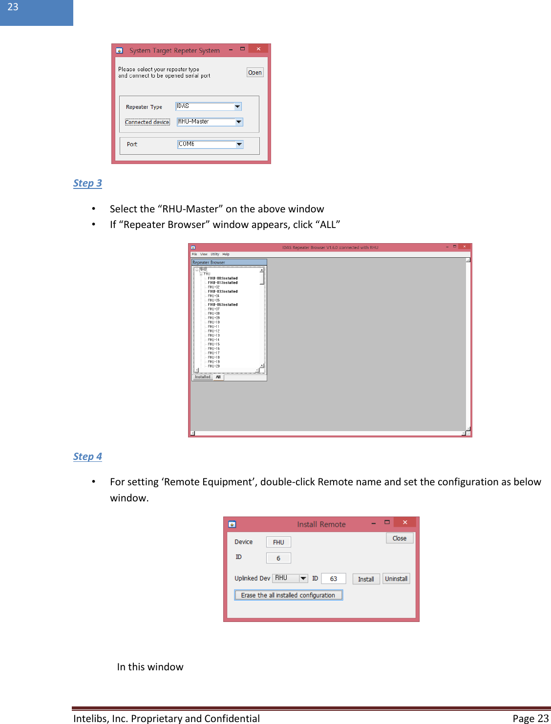
![Intelibs, Inc. Proprietary and Confidential Page 22 22 [Laptop connection to MRU] Figure 4-3 USB connection If the USB connection has been established, LMT is ready to start. Click the short cut icon on your laptop and follows the steps below. Step 1 • Run the IDAS GUI. Step 2 • Select the connection parameters as follows: - Choose [File connect] from GUI window - Repeater Types: IDAS - Connected Device: choose one of RHU-Master, SRU, MRU or FHU - Connections o Serial Port: The port number established via USB](https://usermanual.wiki/Intelibs/D01T4JX6/User-Guide-3247140-Page-22.png)