Intelibs D01T4JX6 Medium power Remote Unit (MRU) User Manual
Intelibs, Inc. Medium power Remote Unit (MRU) Users Manual
Intelibs >
Users Manual

Intelibs, Inc.
Medium power
Remote Unit
Product manual
MRU Operational Manual for GPS-iDAS Application
Version: 1.3
12-16-2016

Intelibs, Inc. Proprietary and Confidential Page 2
2
Contents
1 Introduction .......................................................................................................................................... 4
2 Product Description .............................................................................................................................. 7
2.1 External interface ports and Status Indicators ............................................................................. 8
2.2 Modules ........................................................................................................................................ 9
2.3 Mechanical Drawing ................................................................................................................... 10
2.4 Technical Specifications .............................................................................................................. 11
2.4.1 General specifications ......................................................................................................... 11
2.4.2 Frequency allocation ........................................................................................................... 11
2.4.3 RF specifications .................................................................................................................. 14
2.4.4 Power Specifications ........................................................................................................... 15
3 Installation .......................................................................................................................................... 16
3.1 Installation Tools ......................................................................................................................... 16
3.2 Item Check List ............................................................................................................................ 16
3.3 Unit Mounting ............................................................................................................................. 17
3.4 Antenna ....................................................................................................................................... 17
3.5 Power cable ................................................................................................................................. 18
3.6 Optic cable .................................................................................................................................. 18
4 Configuration and Maintenance ......................................................................................................... 20
4.1 GUI connection ........................................................................................................................... 21
5 Human RF Exposure and Antenna placement guide .......................................................................... 28

Intelibs, Inc. Proprietary and Confidential Page 3
3
FCC WARNING
This equipment generates or uses radio frequency energy. Changes or modifications to this equipment
may cause harmful interference unless the modifications are expressly approved in the instruction
manual. The user could lose the authority to operate this equipment if an unauthorized change or
modification is made.
This is NOT a CONSUMER device. It is designed for installation by FCC LICENSEES and QUALIFIED
INSTALLER. You MUST have an FCC LICENSE or express consent of an FCC License to operate this device.
Unauthorized use may result in significant forfeiture penalties including penalties in excess of $100,000
for each continuing violation.
INFORMATION TO THE USER
This equipment has been tested and found to comply with the limits for a Class B digital device, pursuant
to Part 15 of the FCC Rules. These limits are designed to provide reasonable protection against harmful
interference in a residential installation.
This equipment generates, uses and can generate radio frequency energy and, if not installed and used in
accordance with the instructions, may cause harmful interference to radio communications. However,
there is no guarantee that the interference will not occur in a particular installation. If this equipment
does cause harmful interference to radio or television reception, which can be determined by turning the
equipment off and on, the user is encouraged to try to correct the interference by one or more of the
following measures:
· Reorient or relocate the receiving antenna.
· Increase the separation between the equipment and receiver.
· Connect the equipment to an outlet on a circuit different from that to which the receiver is connected.
· Consult the dealer for technical assistance.
Suitable for use in environmental air space in accordance with Section 300-22 (c) of the National
Electrical Code, and Sections 2-128, 12-010 (3), and 12-100 of the Canadian Electrical Code, Part 1,
C22.1.

Intelibs, Inc. Proprietary and Confidential Page 4
4
1 Introduction
Medium power Remote Unit (MRU) is a part of the Hybrid Distributed Antenna Systems (HDAS) to
provide remote RF coverage solution from the Radio Hub Unit (RHU) fed by the RF source via OTA or
Wireline connection. MRU is built on a small form factor with a single antenna port for dual band
frequencies with the following features:
1. Quadruple-Band support by one box with small form factor
2. Multiple Technology support
3. Low Power consumption fed by PoE or local AC adaptor
4. +33 dBm Down Link Tx Power (Composite power of +36dBm at Antenna port)
5. SNMP based remote management support
6. Single mode Fiber fed with 10 Km distance of 5dBo
7. Auto Gain Control (AGC), Auto power Limit Control (ALC), Auto Shut Down (ASD) and Auto Isolation
detective Gain Control (IGC) function
Including RHU, Hybrid DAS is comprised of the following subsystems:
RHU (Radio Hub Unit): Interface unit between RF source and Remote Units, Convert RF signal into
optical waves.
FHU (Fiber Hub Unit): Fiber distribution and aggregation interface between RHU and multiple RUs.
Each FHU supports up to 4 SRU/MRUs and total up to 16 SRU/MRUs by two level FHU configurations
SRU (Small Remote Unit): Small power (23 dBm per band) remote unit
MRU (Medium Remote Unit): Medium power (33dBm per band) remote unit
RU (Remote Unit): High power (40 dBm per band) remote unit for outdoor/indoor
MU (Master Unit): Element management server
Intelibs, Inc. Proprietary and Confidential Page 5
5
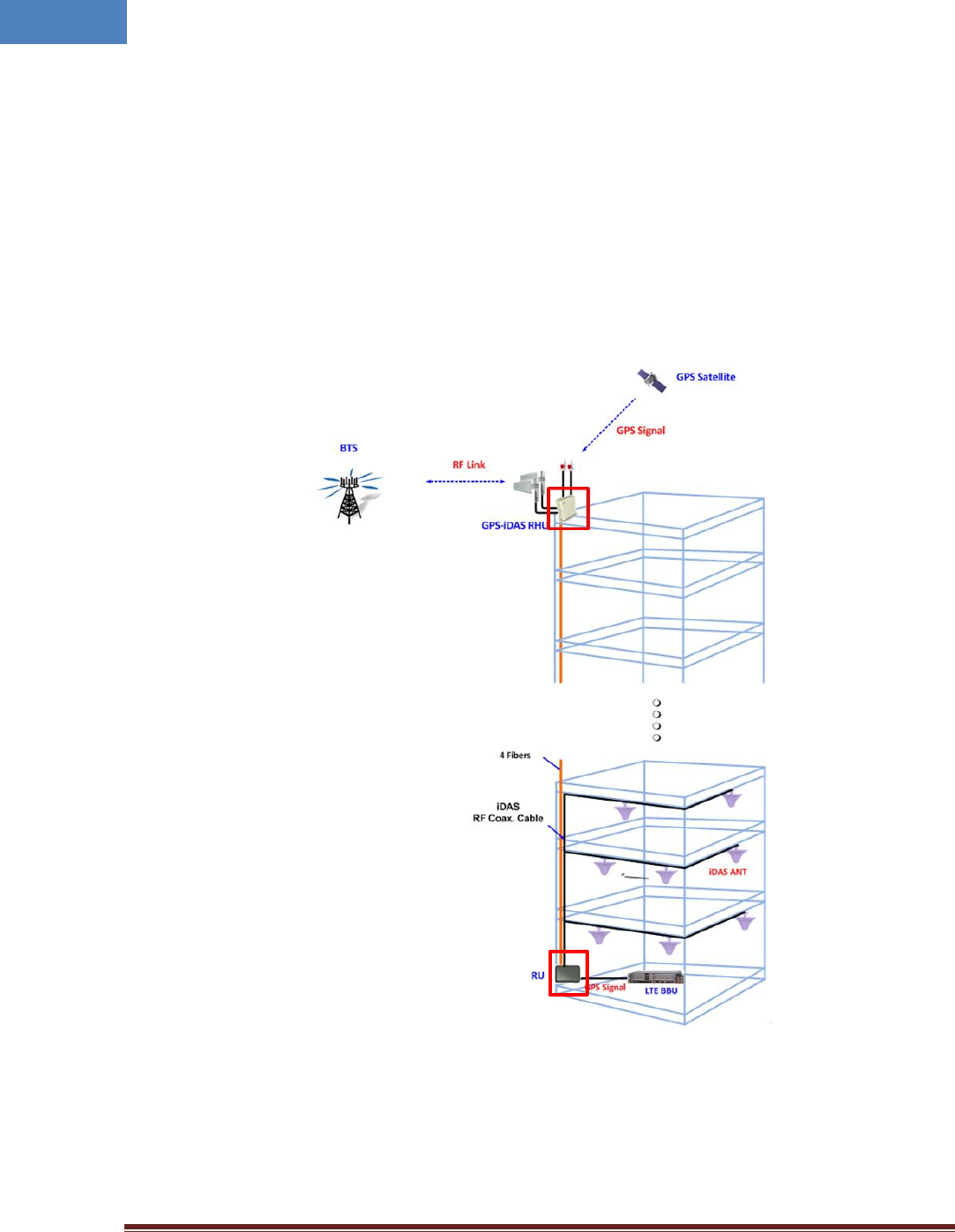
As illustrated in Figure 1-1, Hybrid DAS network is comprised of RHU, FHU, MRU and SRU. Each RHU can
support up to 16 SRU’s that can cover up to 500Ksf2 indoor space or 16MRU’s that can be cover up to
800Ksf2.
(a) RHU-MRU configuration with GPS over fiber
Intelibs, Inc. Proprietary and Confidential Page 6
6
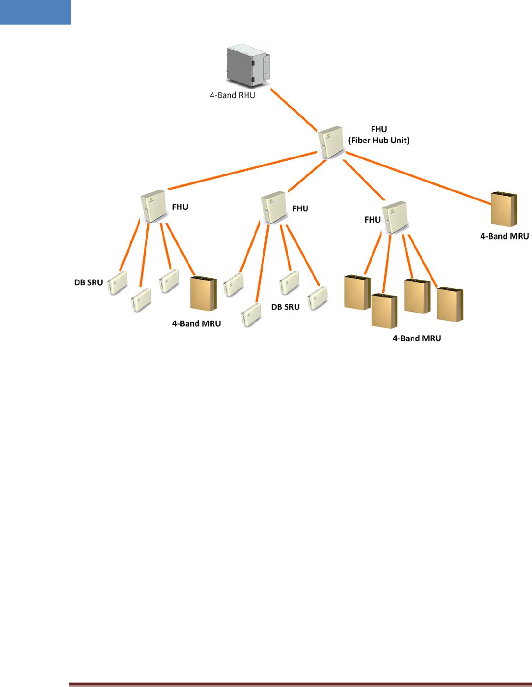
(b) RHU-FHU-MRU/SRU configuration with GPS over fiber
Figure 1-1 Various network diagram using RHU/FHU/MRU/SRU
Intelibs, Inc. Proprietary and Confidential Page 7
7
2 Product Description
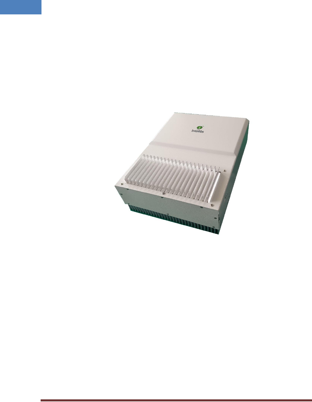
As shown in Figure 2-1, MRU is a compact platform with the natural heat convection. As unified form
factor, MRU services multiple technologies on a single platform with 4 band operating frequencies. It
can be mounted on the wall. Variety of the service antenna can be used from small form factor antenna
to indoor multi-band ceiling Omni antenna (or panel antenna).
Figure 2-1 MRU system
Intelibs, Inc. Proprietary and Confidential Page 8
8
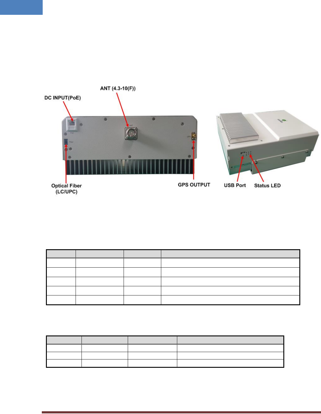
2.1 External interface ports and Status Indicators
MRU has main interface connections at topside of the enclosure, which includes optic, antennas and dc
power input. The status LEDs and USB port for maintenance are located on left side. Figure 2-2 shows
the top and bottom side of MRU.
Figure 2-2 Top and bottom side of MRU
Table 2-1 Interface ports
Port
Connector type
Position
Description
Power
RJ-45
Top
+48V DC inlet, PoE adapter
Debug
USB-A
Left Side
Serial interface for local GUI and debugging
Optic
LC/UPC
Top
Optic fiber connection with FHU or RHU
GPS Out
SMA-Female
Top
GPS signal port to BBU
ANT
4.3-10-Female
Top
Omni ANT connection
Table 2-2 Status indicator LEDs
Name
Normal state
Abnormal state
Description
Power
Green
Off
Power injection status
RUN
Green/Blinking
Off
CPU working status
Alarm
Green
RED
Major Alarm indication
Intelibs, Inc. Proprietary and Confidential Page 9
9
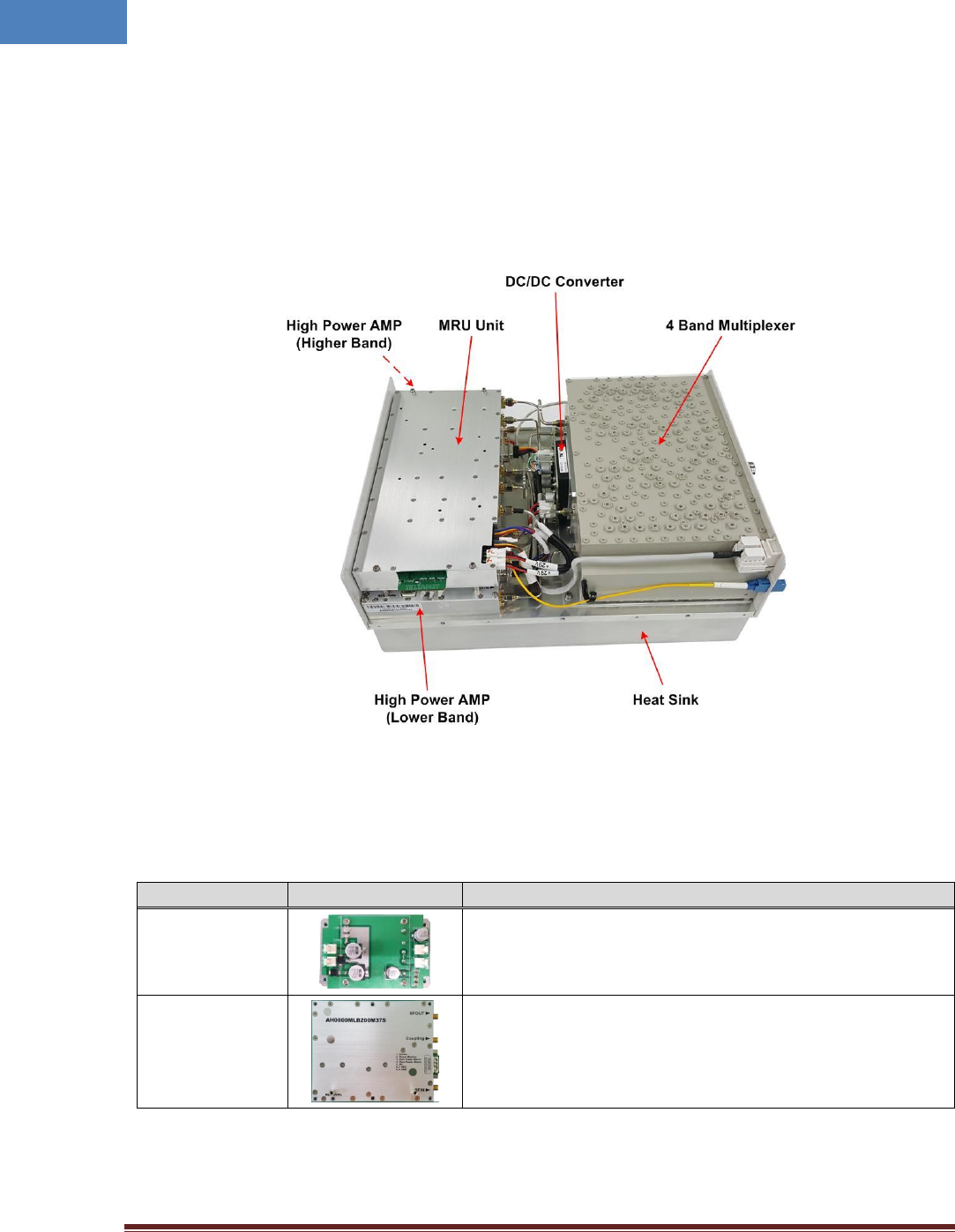
2.2 Modules
MRU is comprised of several internal modules such as 4 Band Multiplexer, DC/DC Converter, MRU Unit
and 2 HPAs which is include FSK modem and main controller. Figure 2-4 shows inside of MRU system.
Figure 2-4 Inside of MRU
Table 2-3 Modules
Module
Picture
Description
DC/DC
Converter
This module converts +48VDC of PoE cable into +29VDC
and provide this DC power to each active module in MRU.
Low Band High
Power Amplifier
This module amplifies low band signal such as 700/850MHz
in order to get high energy and transmit high energy signal
to Multiplexer filter. Composite power can be transmitted
by this amplifier is 2W(33dBm/total).
Intelibs, Inc. Proprietary and Confidential Page 10
10
High Band High
Power Amplifier
This module amplifies high band signal such as
1900/2100MHz in order to get high energy and transmit
high energy signal to Multiplexer filter. Composite power
can be transmitted by this amplifier is 2W(33dBm/total).
RF/Optic
Module
This module converts optic signal from RHU into DL RF
signal and transfer to HPA. In case of Uplink, this module
converts RF UL signal into optic signal to transfer to RHU.
And this module amplifies RF signal to compensate optical
loss. This module has wide band RF matching circuit to
handle 4band signal. And optic wavelength of this module
is 1550nm for Rx and 1310nm for Tx.
Quad Band
Multiplexer
This module filters 4 band(8 path) signal and cut off
unwanted signal strictly. This Quad band multiplexer filter is
at the front-end and cutoff unwanted out of band noise
signals. The combined port of this module is connected to
coverage antenna cable.
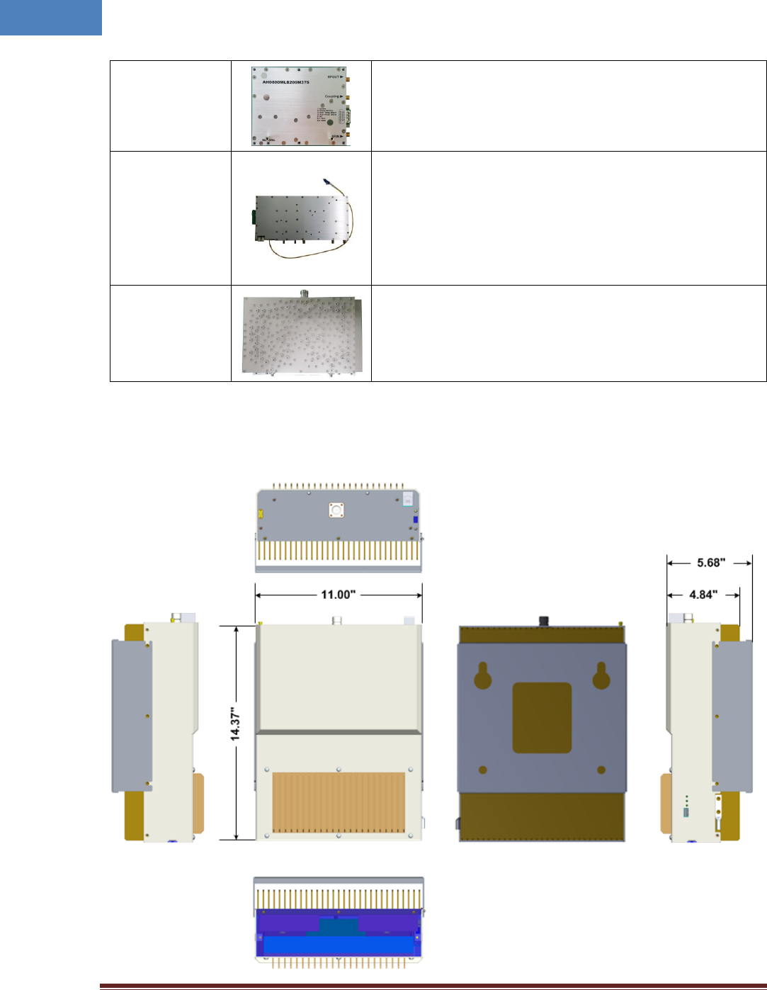
2.3 Mechanical Drawing
Intelibs, Inc. Proprietary and Confidential Page 11
11
Figure 2-5 Exterior in 3-dimension
2.4 Technical Specifications
2.4.1 General specifications
Table 2-4 General Specifications
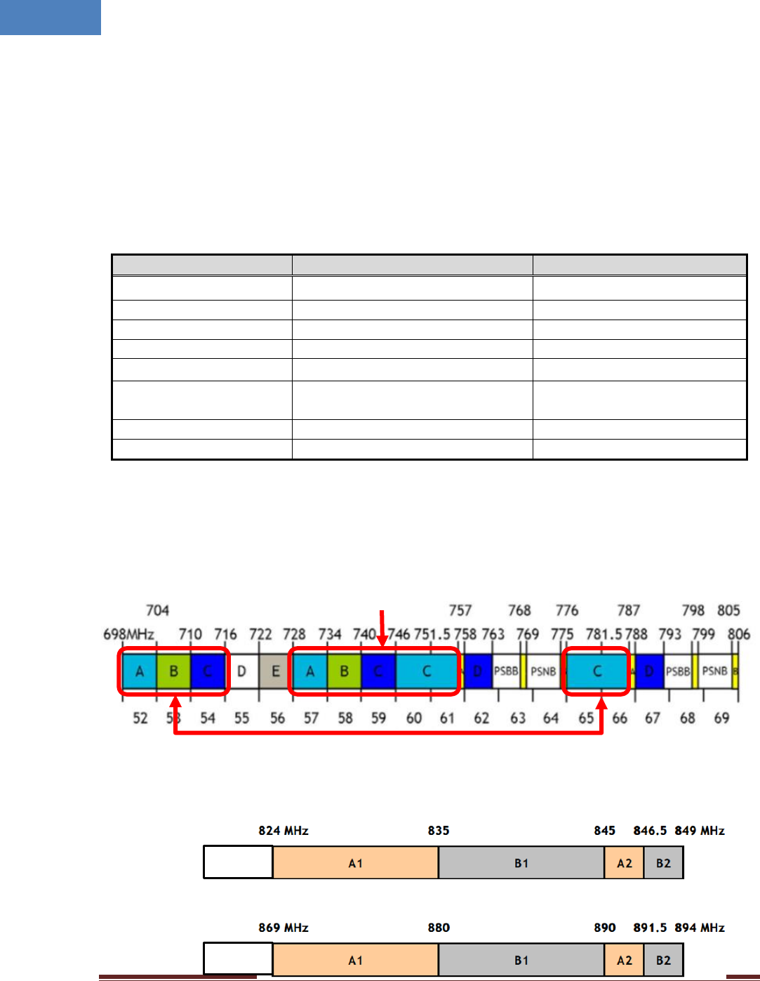
2.4.2 Frequency allocation
2.4.2.1 700MHz band
2.4.2.2 850MHz band
Specification
Values
Remarks
Dimensions
14.37(H) x 11.00(W) x 4.84(D) inch
without holder bracket
Weight
14 Kg (31 lb)
ANT and RF connector
4.3-10 Female
Optic port
LC/UPC type
GUI port
USB A-type
Input Supply Voltage
+48VDC
PoE adapter or AC/DC
converter
Operating Temperature
-10 ~ +45 °C
Humidity
5 ~ 80% Relatively
Down Link
Up Link
817 MHz
862 MHz
Uplink
Downlink
Intelibs, Inc. Proprietary and Confidential Page 12
12
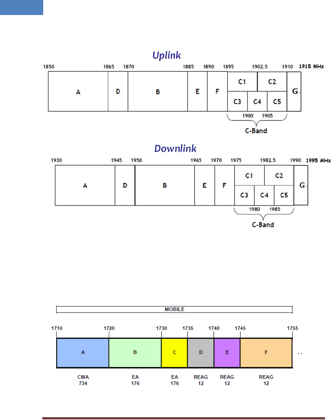
2.4.2.3 1900MHz band
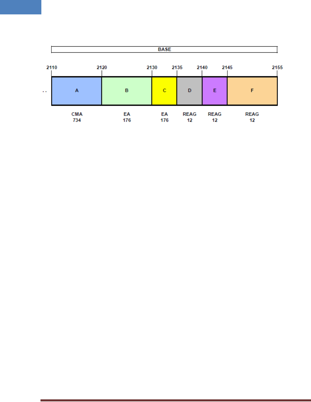
2.4.2.4 AWS band
Up Link
Intelibs, Inc. Proprietary and Confidential Page 13
13
Down Link

Intelibs, Inc. Proprietary and Confidential Page 14
14
2.4.3 RF specifications
2.4.3.1 iDAS MRU specifications
Table 2-5 Power specifications
Specification
Values
Remarks
Frequency Band
DL
700LTE: 728 ~ 757MHz 850MHz: 862 ~ 894MHz
PCS: 1930 ~ 1995MHz AWS: 2110 ~ 2155MHz
UL
700LTE: 698~716/776~787MHz 850MHz: 817 ~ 849MHz
PCS: 1850 ~ 1915MHz AWS: 1710 ~ 1755MHz
System input level
DL
-15 ~ -5dBm/band
@ MRU optic output port
UL
-45dBm/band max.
@ ANT input port of MRU
Composite Power
DL
+33dBm/Total(High/Low)
+30dBm/band max.
@ Composite PWR of MRU
UL
-5dBm/Band max.
@ Optic input port of MRU
System Gain
DL
45dB typ.(50dB max.)
@ Be able to compensate
5dBo fiber loss
UL
45dB typ.(50dB max.)
Gain Control Range
DL
0 ~ 30dB by 1dB step
@ ±0.7dB error at 0~25dB
UL
0 ~ 30dB by 1dB step
Noise Figure
UL
5dB typ. (8dB max.)
@ MRU RHU
VSWR
DL/UL
1.5: 1 Max.
@ All of RF Port
Output spurious
DL/UL
Comply to 3GPP/3GPP2/FCC
@ Composite out power
System Delay
DL/UL
200nsec max.
EVM
DL/UL
Less than 5%
@ CDMA, WCDMA, LTE signal
Optical wavelength
DL
1310nm
@ WDM included
UL
1550nm
Optical loss
DL/UL
5dBo max.
@ RHU 4band RU
Supply Voltage &
/Consumption
RU
+40 ~ +55VDC / 150W typ.
@ When all DL bands are
transmitted by 1W
Connector type
RF
4.3-10 Female
@ ANT port
Optic
LC/UPC
Power
RJ-45 for PoE
@ MS-Female for AC Input
Debug
USB-A type
Temperature
-10 ~ +45°C
@ Indoor type
Humidity
5 ~ 80% Relatively

Intelibs, Inc. Proprietary and Confidential Page 15
15
2.4.4 Power Specifications
Table 2-6 Power specifications
Item
Specification
Rated Input Voltage
1. +40 ~ +55 VDC typ.
Permissible range
2. Tolerance ±5%
Power consumption
150W typ. 170W max.
Intelibs, Inc. Proprietary and Confidential Page 16
16
3 Installation
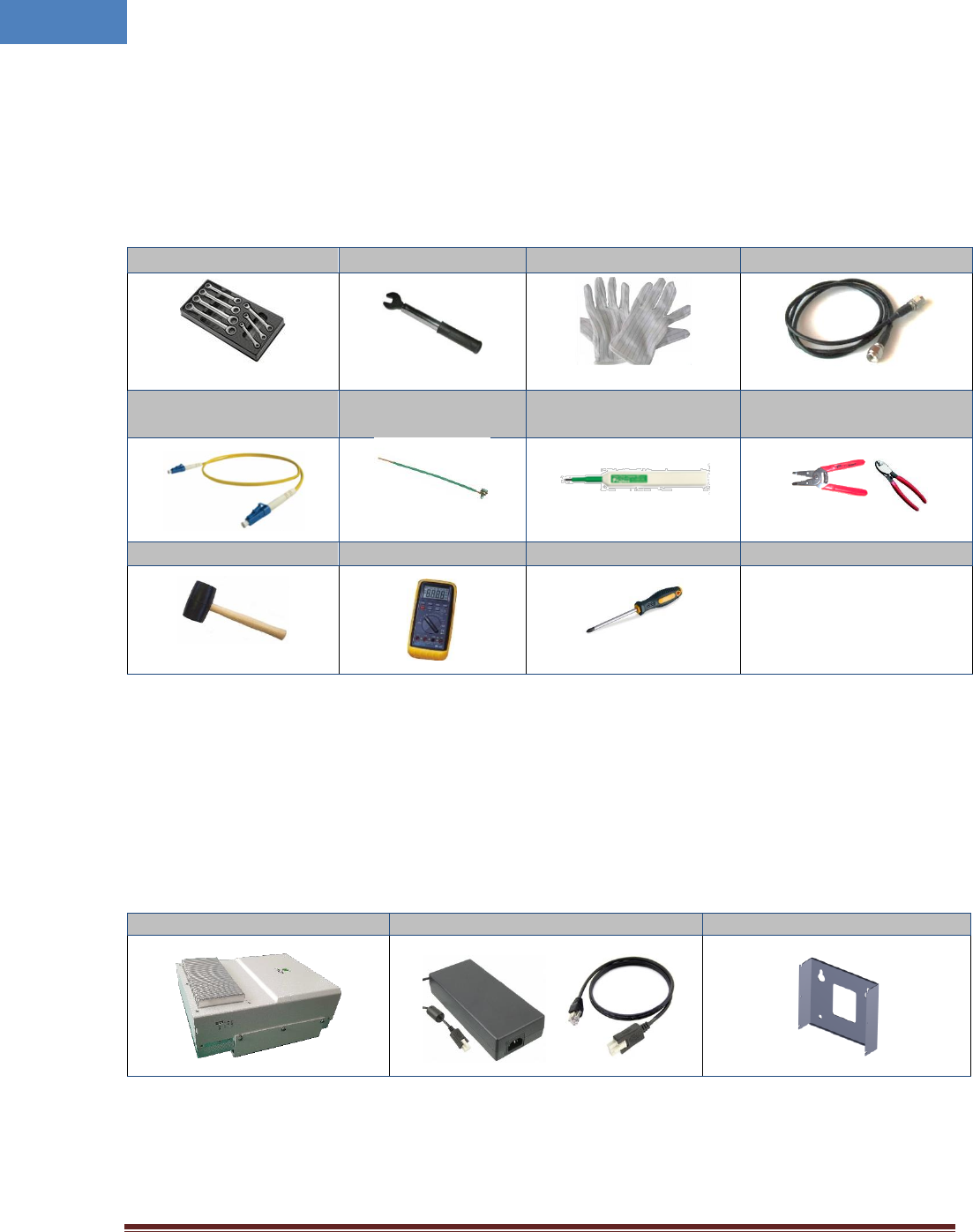
3.1 Installation Tools
Table 3-1 Installation tools
3.2 Item Check List
Check that all the following items have been included with the box delivered. If anything is missing,
please contact Intelibs.
Table 3-2 Item check list
MRU
AC/DC Power Adaptor w/ PoE Cable
Bracket
Torque Wrench
4.3-10 Torque Wrench
ESD Gloves
Antenna cable w/ 4.3-10(M)
LC/UPC-LC/UPC
Optic Fiber, 10m
Ground wire line
Optic connector cleaner
Wire Stripper & Cutter
Rubber Mallet
Digital Multi-meter
Screw Driver
Intelibs, Inc. Proprietary and Confidential Page 17
17
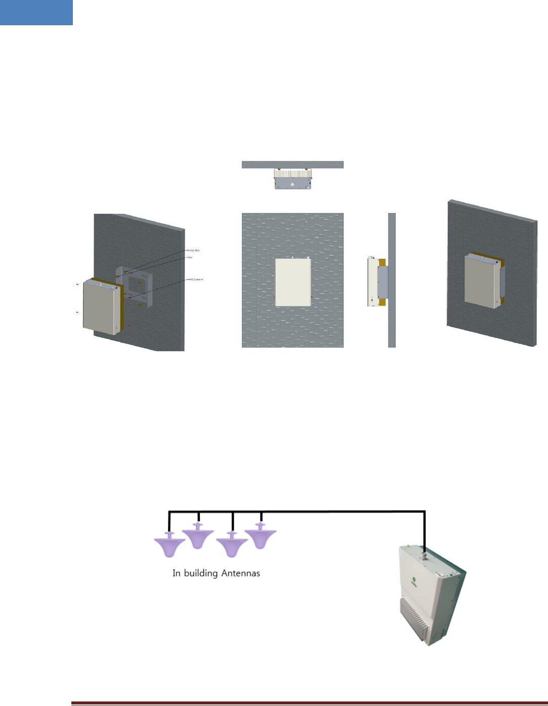
3.3 Unit Mounting
MRU should be installed vertically such as wall mounting because of heat dissipation. If MRU want to be
installed on the rack horizontally, proper cooling devices like fan are required. The following diagrams
illustrate the methods for mounting MRU in a typical wall. The brackets for wall mount are provided
with MRU system.
Figure 3-1 Wall mounting
3.4 Antenna
MRU uses various antennas depends on its application and environment. MRU provides one antenna
port for 4-Band transmission at the top side of the system. Figure 3-2 shows antenna connection with
1/2inch coaxial cable in case of passive DAS.
Figure 3-2 Antenna connection
Intelibs, Inc. Proprietary and Confidential Page 18
18
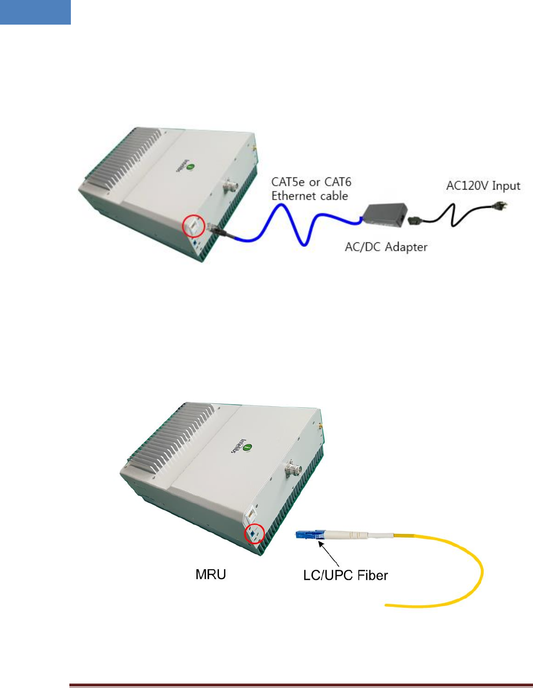
3.5 Power cable
MRU uses +48V DC power by PoE passive injector. For DC power source, AC/DC converter or PoE (Power
over Ethernet) adaptor can be used. Connect DC connector power cable to the “DC” port.
Figure 3-3 Power cable connection
3.6 Optic cable
MRU provides one optic port for upward direction, “Optic” port, and optic connector type is LC/UPC .
Figure 3-4 Optic cable connection
Intelibs, Inc. Proprietary and Confidential Page 19
19
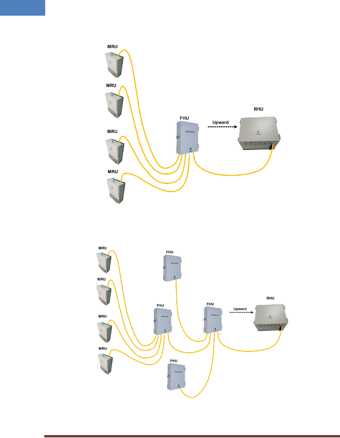
Figure 3-5 and 3-6 shows various optic connection of RHU-FHU-MRU equipment.
Figure 3-5 Optic cabling when cascading DAS systems with one FHU
Figure 3-6 Optic cabling when cascading DAS systems with two-stage FHU
Intelibs, Inc. Proprietary and Confidential Page 20
20
4 Configuration and Maintenance
SRU can be configured in three ways via remote internet connection or local serial port connection.
Local management interface through the internet or serial connection
Web interface through the internet
SNMP interface through the internet
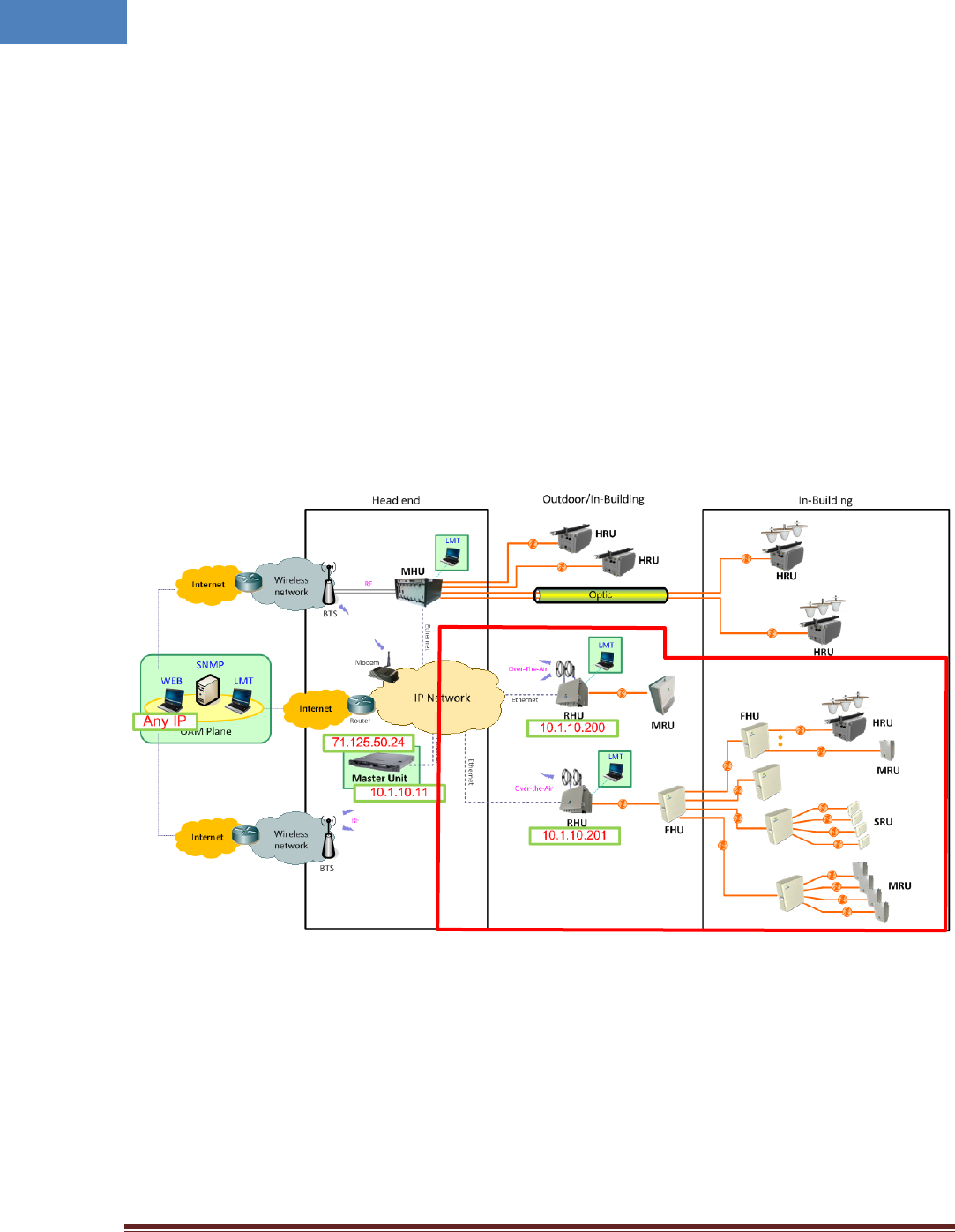
Master Unit is a remote management system that provides SNMP and Web interface, and maintains all
functions of optical DAS system including configurations, monitoring, and real time alarm reporting.
The local management interface can be set up through IP network, serial interface, and Bluetooth.
The configuration and maintenance for SRU is performed by accessing RHU system through any
interfaces provided by RHU.
Figure 4-1 DAS management network and entities
Intelibs, Inc. Proprietary and Confidential Page 21
21
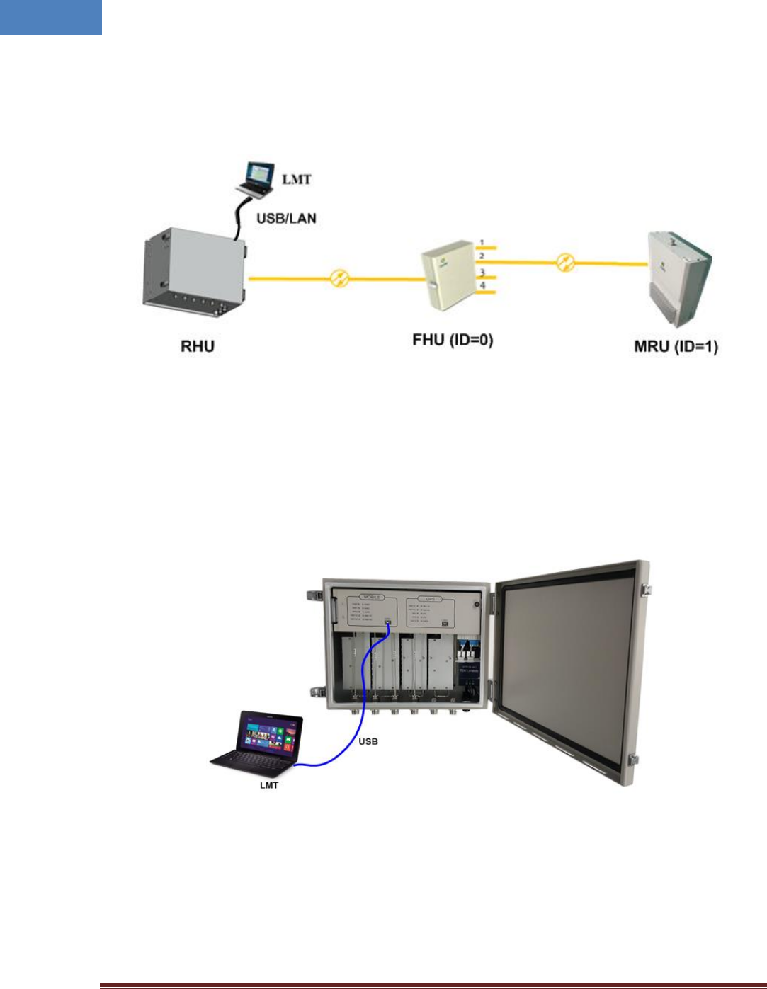
Configuration guide below shows how to configure and manage MRU system. Figure 2-15 is an example
DAS network for the configuration.
Figure 4-2 RHU/FHU/MRU network
4.1 GUI connection
The on-site local connection between LMT and RHU system can be established via USB interface.
[Laptop connection to MHU]
Intelibs, Inc. Proprietary and Confidential Page 22
22
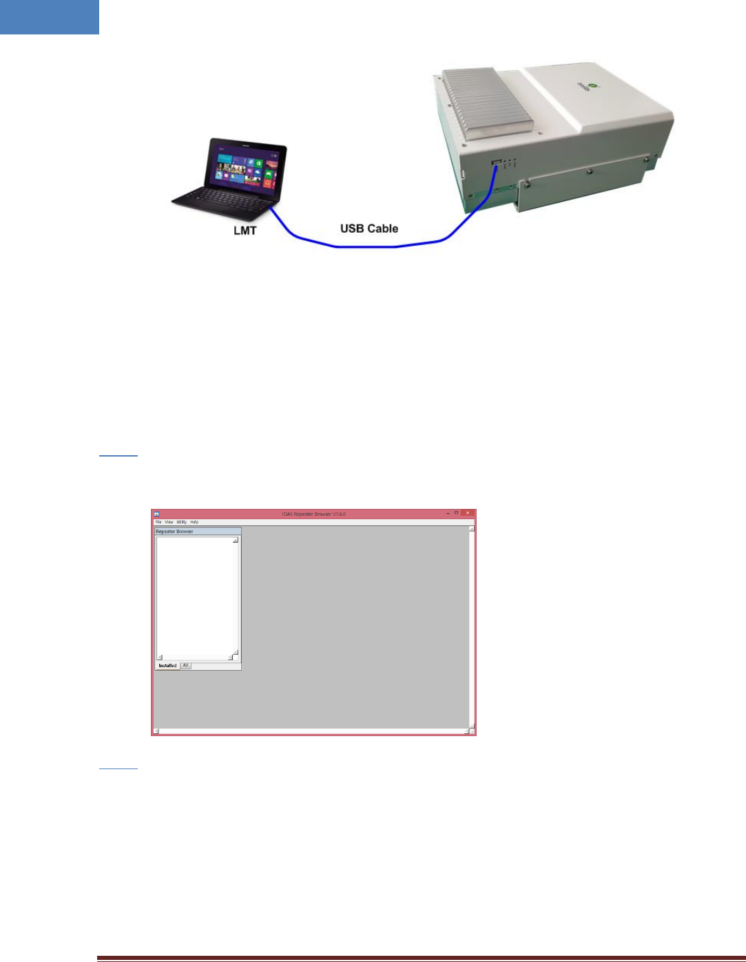
[Laptop connection to MRU]
Figure 4-3 USB connection
If the USB connection has been established, LMT is ready to start. Click the short cut icon on your laptop
and follows the steps below.
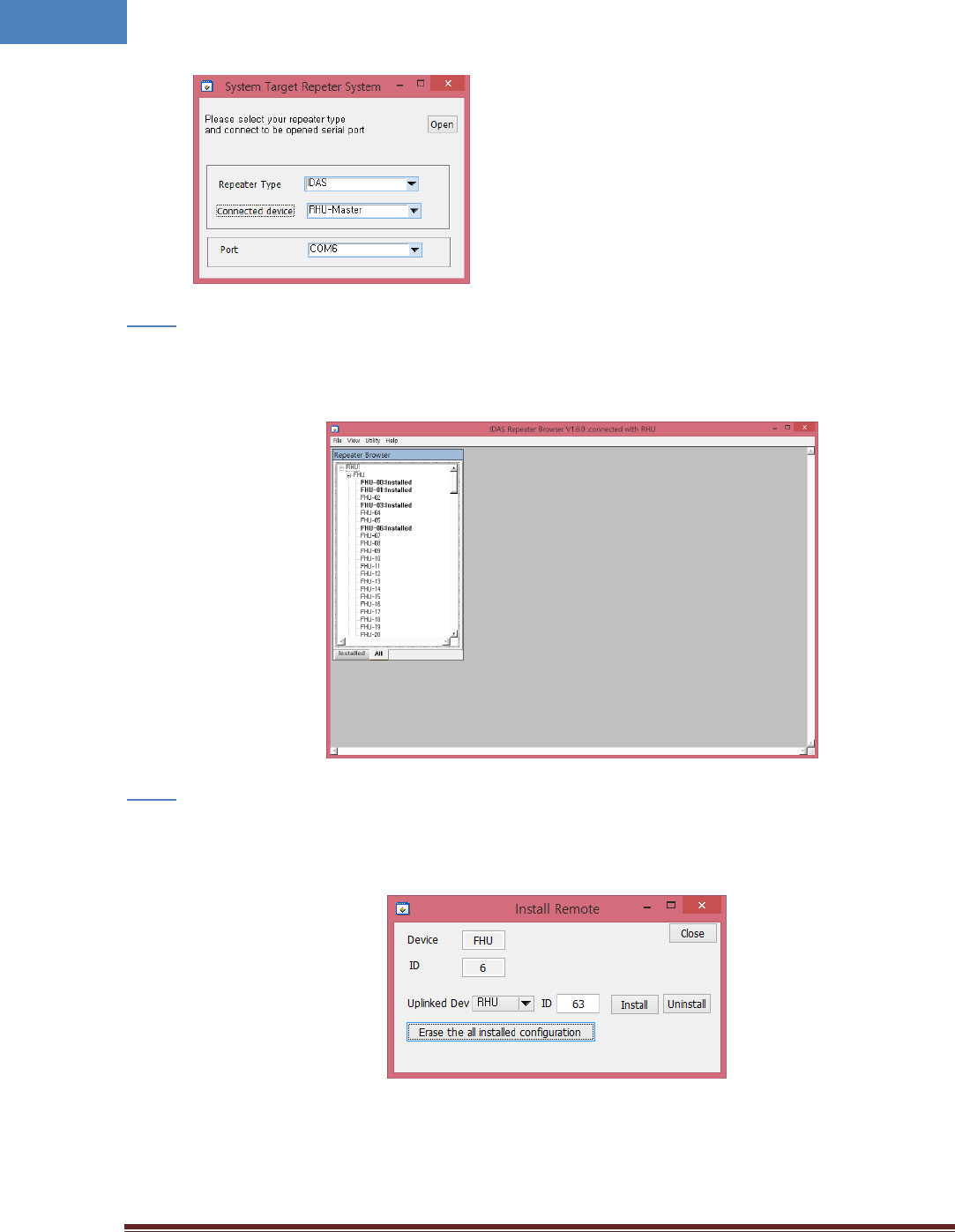
Step 1
• Run the IDAS GUI.
Step 2
• Select the connection parameters as follows:
- Choose [File connect] from GUI window
- Repeater Types: IDAS
- Connected Device: choose one of RHU-Master, SRU, MRU or FHU
- Connections
o Serial Port: The port number established via USB
Intelibs, Inc. Proprietary and Confidential Page 23
23
Step 3
• Select the “RHU-Master” on the above window
• If “Repeater Browser” window appears, click “ALL”
Step 4
• For setting ‘Remote Equipment’, double-click Remote name and set the configuration as below
window.
In this window
Intelibs, Inc. Proprietary and Confidential Page 24
24
- Uplinked Dev : Uplink Device
- ID : Uplinked Device ID
- Install : Add the modules from uplink device
- Uninstall : Remove the modules from uplink device
- Erase the all installed configuration : Remove all modules.
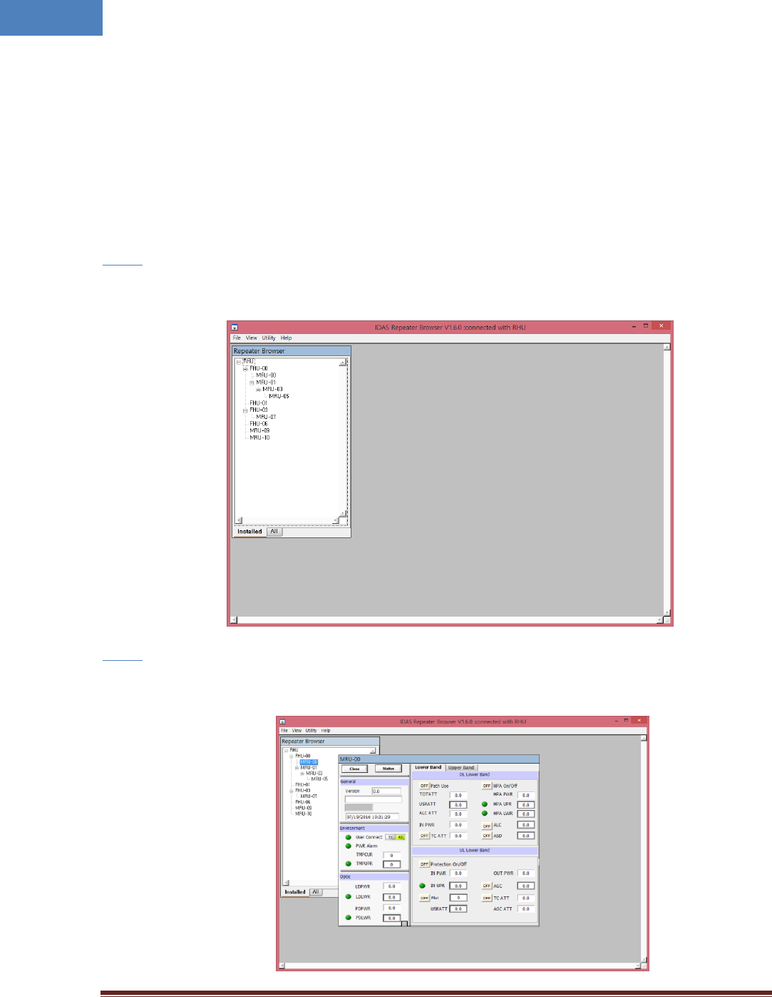
Step 5
• Check the installed device as below browser
Step 6
• Click “MRU” from above browser
Intelibs, Inc. Proprietary and Confidential Page 25
25
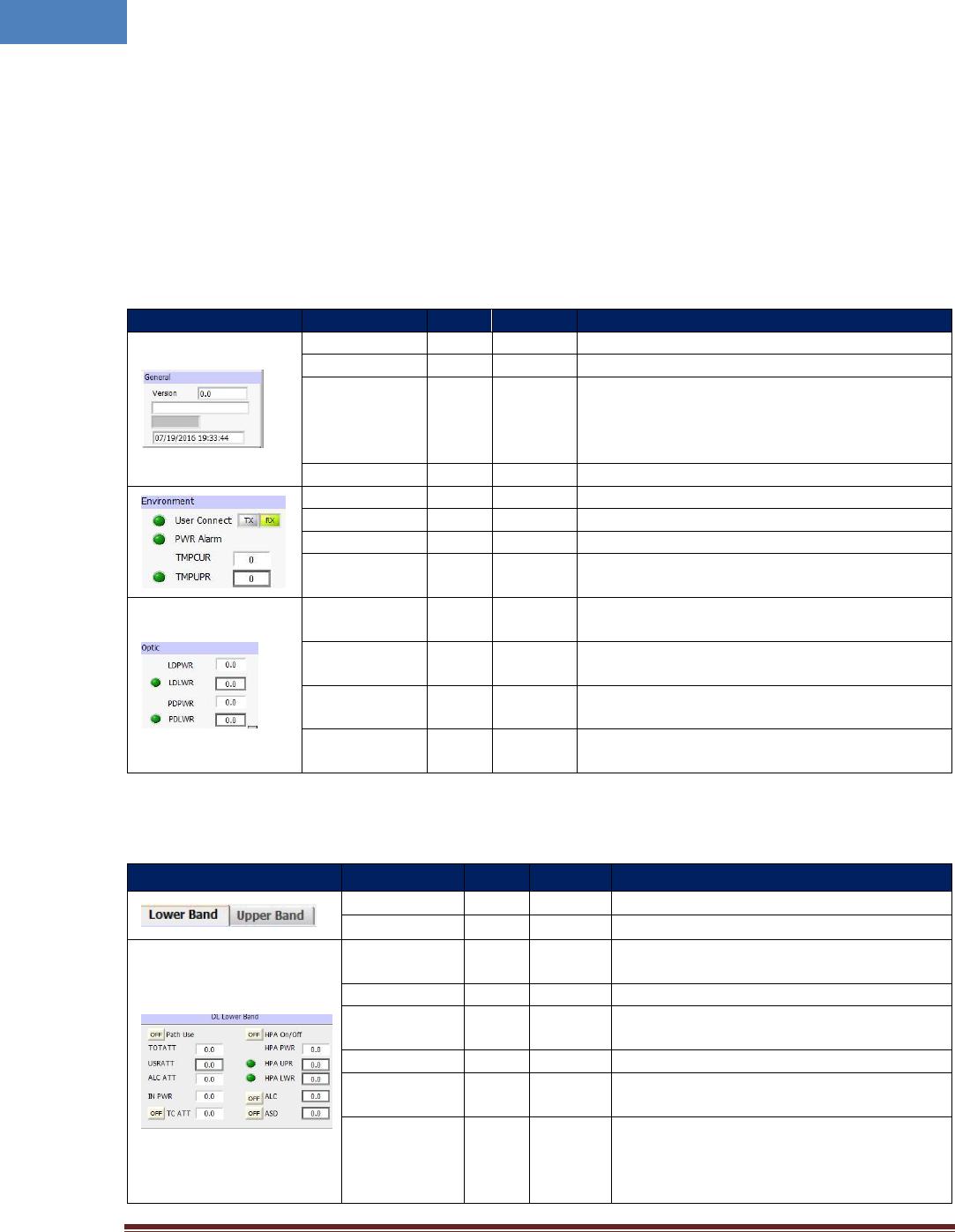
If connection is established successfully, then all parameters of MRU can be set by LMT terminal, and all
status information can be reported to LMT. MRU’s status and parameters controllable by LMT are
described in Table 4-1, 4-2, and 4-3.
Table 4-1 General/Environment/Optic
Status group
Parameters
Status
Control
Description
Version
√
Firmware Version of the Unit
DAS Type
√
The type of the DAS system
Name
√
√
Set following information of the DAS
- Name
- Model Number
- Serial Number
Time/UpTime
√
Current time or Up-time display
User Connect
√
Connection status with RHU
PWR Alarm
√
Display DC Power Alarm
TMPCUR
√
Current chassis temperature of the Unit
TMPUPR
√
√
Set temperature upper limit, and display its value
and alarm status.
LDPWR
√
Current optical output power of LD (Laser Diode)
to transmit to upper unit.
LDLWR
√
√
Set the lower limit of output power of LD, and
display its value and alarm status.
PDPWR
√
Current optical receiving power of PD (Photo
Detector) of optic module connected to MRU.
PDLWR
√
√
Set the lower limit of PD power, and display its
value and alarm status.
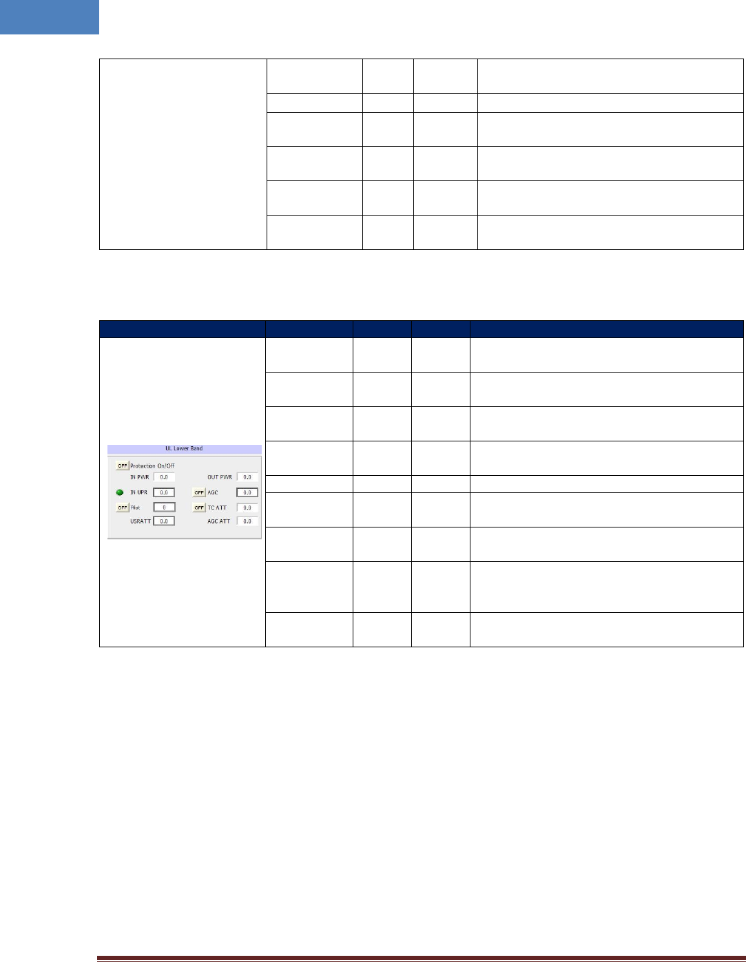
Table 4-2 DL Lower and Upper Band
Status group
Parameters
Status
Control
Description
Lower Band
√
Selects Lower Band (700/850MHz) channel
Upper Band
√
Selects Upper (1900MHz/AWS) channel
Path Use
√
√
Turn On/Off of the usage of this path and
display its status
TOTATT
√
Downlink downlink total attenuation value
USR ATT
√
√
Set user configurable downlink attenuation
value
ALC ATT
√
Attenuation value due to DL ALC function
IN PWR
√
Display the downlink input level coming
from upper unit
TC ATT
√
Displays downlink temperature
compensation attenuation value and
enable/disable downlink temperature
compensation function.
Intelibs, Inc. Proprietary and Confidential Page 26
26
HPA On/Off
√
√
Turn On/Off downlink HPA (High Power
Amplifier).
OUT PWR
√
Display downlink output power to ANT port
OUT UPR
√
√
Set upper limit of downlink output power,
and displays its value and alarm status
OUT LWR
√
√
Set lower limit of downlink output power,
and displays its value and alarm status
ALC
√
√
Set ALC (Automatic Level Control) function’s
activation level, and enable/disable ALC.
ASD
√
√
Set ASD (Automatic Shut Down) function’s
activation level, and enable/disable ASD.
Table 4-3 UL Lower and Upper Band
Status group
Parameters
Status
Control
Description
Protection
On/Off
√
√
Enable/disable uplink protection function.
IN PWR
√
Displays uplink receiving power from ANT
port
IN UPR
√
√
Set upper limit of uplink input power, and
displays its value and alarm status
Pilot
√
√
Enable/disable uplink Pilot signal and selects
uplink CW channel.
ATT
√
√
Set uplink attenuation, and displays its value.
OPWR
√
Displays uplink output power that is
transmitted from MRU
AGC
√
√
Set AGC (Automatic Gain Control) function’s
activation level, and enable/disable AGC.
TC ATT
√
√
Displays uplink temperature compensation
attenuation value, and enable/disable uplink
temperature compensation.
AGC ATT
Displays attenuation value due to AGC
(Automatic Gain Control) operation
Intelibs, Inc. Proprietary and Confidential Page 27
27
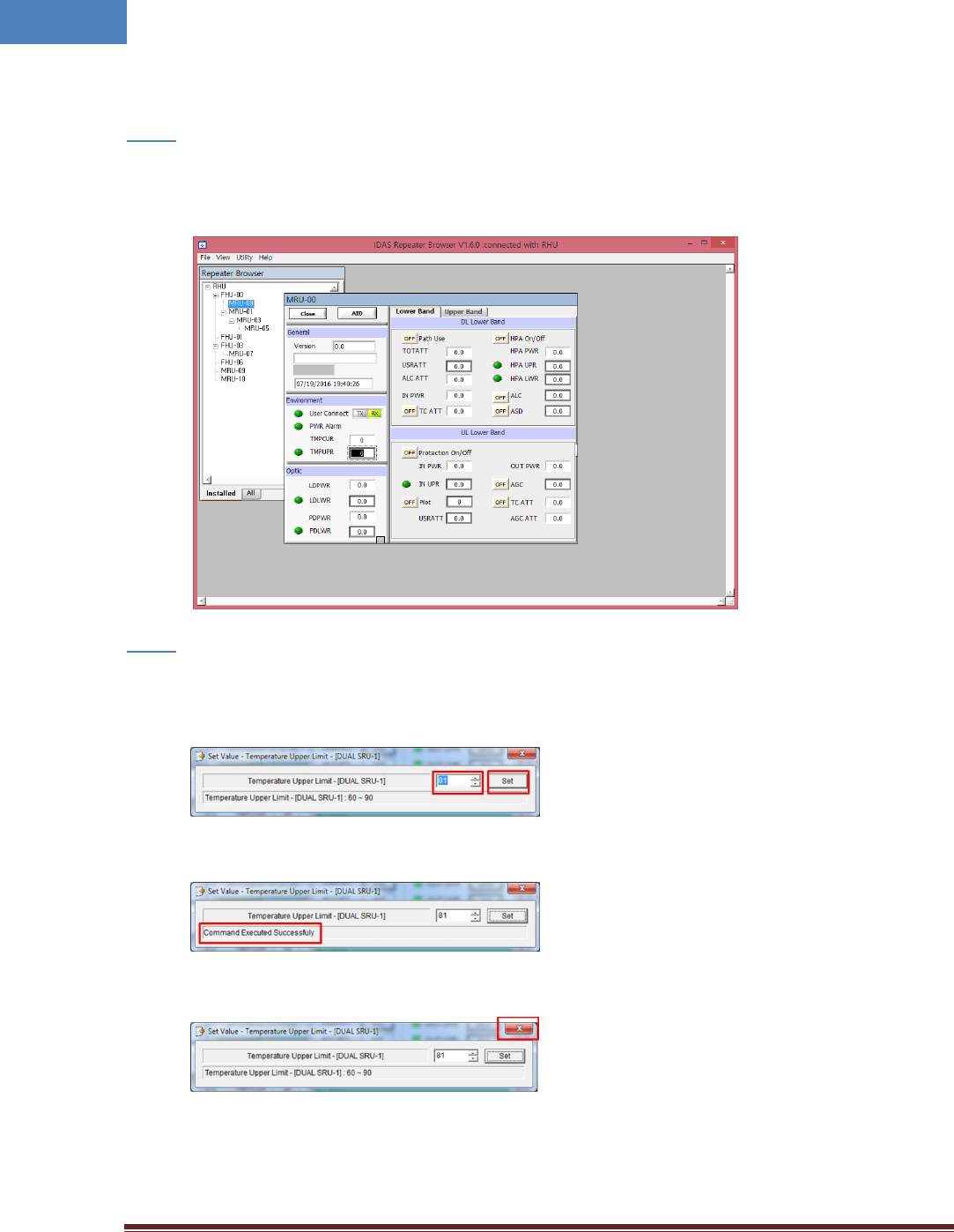
Following is one example of LMT operation which sets the upper limit of MRU chassis’ temperature.
Step 1
• Click the box which is on the right side of “TMPUPR”. A number in the box represents current
upper limit of chassis’ temperature and change the value. And then enter the key.
Step 2
• Enter desired TMPUPR value by clicking arrow button or entering number. Then press “Set”
button.
• Then the bottom of the window shows result of command.
• Press close button on the upper right corner of the window to exit the command window.
The small color box on the left side of “TMPUPR” represents current status of upper limit of
MRU chassis’ temperature. If the box is GREEN, operating status is in normal condition. If the
box is RED, “TMPUPR” alarm occurred and remains.

Intelibs, Inc. Proprietary and Confidential Page 28
28
5 Human RF Exposure and Antenna placement guide
Actual distance is determined upon gain of antenna used. Please maintain a minimum safe distance of at
least 110 cm while operating near the service antennas with maximum permissive antenna gain up to 15
dBi and 10 dBi when 862 – 869 MHz frequency band is serviced.

Intelibs, Inc. Proprietary and Confidential Page 30
30
Two Year Limited Warranty
Intelibs, Inc. (“Intelibs”) offers a standard two year warranty from defects in material and installation.
INTELIBS may at any time exclude from this Agreement any Hardware or Software which (1) has been
modified, repaired or serviced by anyone other than Intelibs’ service staff without the prior written
approval of Intelibs, (2) has been subjected to unusual physical or electrical stress, whether such stress
results from accident, neglect, misuse, lightning, failure of electrical power, air conditioning, humidity
control, transportation, the making of specification or configuration changes requested by Customer, or
any other cause other than ordinary use, and whether or not such stress is the fault of the Customer, (3)
has been purchased from another Vendor and is networked, linked, attached or otherwise intended to
work with the System or (4) has been moved from the place of installation. When the system has been
improperly modified, repaired, stressed, used or moved as described above, Intelibs may, at its option
and subject to the approval of the Customer, perform such corrective work, including any repairs,
replacements and adjustments, as are in Vendor’s opinion necessary to restore the System to the
condition it would have been in if subjected only to normal wear and tear at the Customer’s expense.

Intelibs, Inc. Proprietary and Confidential Page 31
31
Index
3-Way Combiner .............................................. 10
AC Power specifications ............................. 14, 15
AGC .................................................................. 26
Bluetooth ................................................... 20, 21
DAS management network .............................. 20
DAS Type .......................................................... 25
FC-APC .............................................................. 18
FHU ..................................................................... 4
IN ATT ......................................................... 25, 26
IN LWR .............................................................. 26
IN PWR ....................................................... 25, 26
IN UPR .............................................................. 26
LDLWR .............................................................. 25
LDPWR.............................................................. 25
Link Antenna connection ................................. 17
LMT ............................................................ 21, 25
Local management interface ........................... 20
Mounting methods .......................................... 17
MU ..................................................................... 4
NMS Controller ................................................ 10
Optic cable connection .................................... 18
OUT PWR ......................................................... 26
PDLWR ............................................................. 25
PDPWR ............................................................. 25
Power cable connection .................................. 18
PSU ................................................................... 25
Rated Input Voltage ......................................... 15
RHU .................................................................... 4
RU ...................................................................... 4
SNMPv3 ........................................................... 20
SRU ..................................................................... 4
TMPCUR ........................................................... 25
TMPUPR ..................................................... 25, 27
Version ............................................................. 25
Web interface .................................................. 20