Intelibs D01T4X3 DAS Remote Unit-ASW Band User Manual
Intelibs, Inc. DAS Remote Unit-ASW Band
UserManual.wiki
>
Intelibs
>
D01T4X3 User Manual
User Manual
Navigation menu
Upload a User Manual
Namespaces
Wiki Guide
HTML
PDF
Info
Views
User Manual
Discussion / Help
Navigation

![Intelibs, Inc Proprietary and Confidential Page 30 30 4.1 Configuring RU using LMT If one of serial or LAN connection has been established, LMT is ready to start. Launch the Local Management application by clicking the icon “Cherry” and follows the steps below. • Launch the application “Cherry”. Step 1 • Enter the password, click “Login”. • Click “Connect” icon on the left top corner of window or click [File]-[connect] menu. • Select the connection parameters as follows: Step 2 - Repeater Types: VzW LTE Outdoor System - Connected Device: MHU [Dual Band / LTE] - Connections o Serial Port: The port number established via serial interface or o UDP: IP address for the Ethernet interface • Click “Select Done” button.](https://usermanual.wiki/Intelibs/D01T4X3/User-Guide-2169880-Page-30.png)
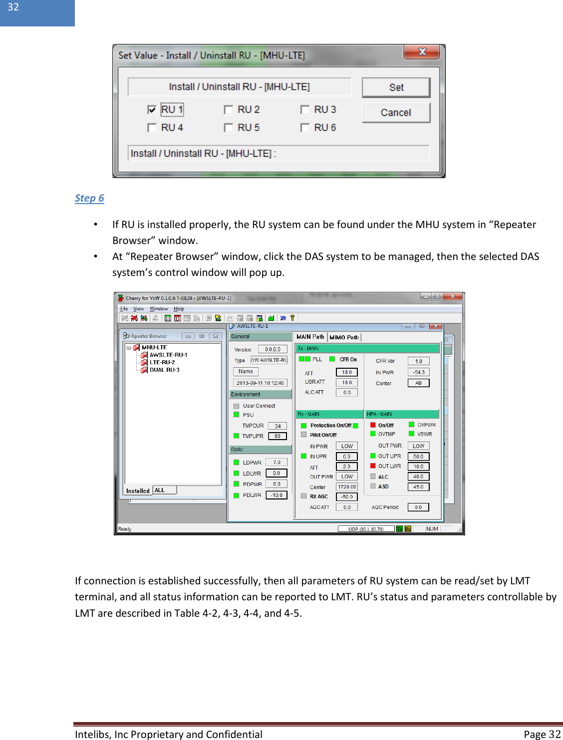
![Intelibs, Inc Proprietary and Confidential Page 31 31 • If “Repeater Browser” window appears, click MHU-LTE system. Step 3 • Click any place inside of “Install” panel area. Step 4 • At “Install / Uninstall RU – [MHU-LTE]” window, click the RU systems that has been installed according to MHU’s port number that is connected via optic cable. Step 5 • Then click “Set” button.](https://usermanual.wiki/Intelibs/D01T4X3/User-Guide-2169880-Page-31.png)