Intelibs D01T4X3 DAS Remote Unit-ASW Band User Manual
Intelibs, Inc. DAS Remote Unit-ASW Band
Intelibs >
User Manual

Intelibs, Inc
AWS Band
Remote Unit
Product Manual
RU-AWS Ope rat ional M anua l
Ve rsion : 1.1
09-30 -2013

Intelibs, Inc Proprietary and Confidential Page 2
2
Contents
1 Introduction .......................................................................................................................................... 6
2 Product Description .............................................................................................................................. 8
2.1 Network configuration .................................................................................................................. 8
2.2 External interface ports ................................................................................................................ 9
2.3 Modules ...................................................................................................................................... 11
2.4 Mechanical Drawing ................................................................................................................... 12
2.5 Technical Specifications .............................................................................................................. 14
2.5.1 General specifications ......................................................................................................... 14
2.5.2 2100 MHz AWS band frequency allocation ........................................................................ 14
2.5.3 RF specifications .................................................................................................................. 15
2.5.4 Power Specifications ........................................................................................................... 16
3 Installation .......................................................................................................................................... 17
3.1 Installation Requirements ........................................................................................................... 17
3.1.1 General Safety Precautions ................................................................................................. 17
3.2 Installation Tools ......................................................................................................................... 18
3.3 Item Check List ............................................................................................................................ 18
3.4 Mounting ..................................................................................................................................... 19
3.5 Link (Donor) Antenna .................................................................................................................. 22
3.6 Power cable ................................................................................................................................. 23
3.7 Optic cable .................................................................................................................................. 23
3.8 RF power setting ......................................................................................................................... 24
3.8.1 Down Link power setting .................................................................................................... 24
3.8.2 Up Link power setting ......................................................................................................... 26
4 Configuration and Maintenance ......................................................................................................... 27
4.1 Configuring RU using LMT ........................................................................................................... 30
4.2 Example: Setting the Temperature Upper Limit ......................................................................... 35
4.3 Web interface ............................................................................................................................. 36
5 Appendix I. Ancillary Devices – Antenna, Cable and other Passive Device ........................................ 42

Intelibs, Inc Proprietary and Confidential Page 3
3

Intelibs, Inc Proprietary and Confidential Page 4
4
FCC WARNING
This equipment generates or uses radio frequency energy. Changes or modifications to this equipment
may cause harmful interference unless the modifications are expressly approved in the instruction
manual. The user could lose the authority to operate this equipment if an unauthorized change or
modification is made.
This is NOT a CONSUMER device. It is designed for installation by FCC LICENSEES and QUALIFIED
INSTALLER. You MUST have an FCC LICENSE or express consent of an FCC Licensee to operate this device.
Unauthorized use may result in significant forfeiture penalties including penalties in excess of $100,000
for each continuing violation.
INFORMATION TO THE USER
This equipment has been tested and found to comply with the limits for a Class A digital device,
pursuant to Part 15 of the FCC Rules. These limits are designed to provide reasonable protection against
harmful interference when the equipment is operated in a commercial environment.
This equipment generates, uses and can generate radio frequency energy and, if not installed and used
in accordance with the instructions, may cause harmful interference to radio communications. However,
there is no guarantee that the interference will not occur in a particular installation. If this equipment
does cause harmful interference to radio or television reception, which can be determined by turning the
equipment off and on, the user is encouraged to try to correct the interference by one or more of the
following measures:
· Reorient or relocate the receiving antenna.
· Increase the separation between the equipment and receiver.
· Connect the equipment to an outlet on a circuit different from that to which the receiver is connected.
· Consult the dealer for technical assistance.
Suitable for use in environmental air space in accordance with Section 300-22 (c) of the National
Electrical Code, and Sections 2-128, 12-010 (3), and 12-100 of the Canadian Electrical Code, Part 1, C22.1.
This device complies with part 15 of the FCC Rules. Operation is subject to the following two conditions:
(1) This device may not cause harmful interference, and (2) This device must accept any interference
received, including interference that may cause undesired operation.

Intelibs, Inc Proprietary and Confidential Page 5
5
CAUTION Any changes or modificat ions not expressly approved by t he manuf act ur er could void t he
user's aut horit y t o operat e t he equipment . This equipment is int ended f or use only wit h Int elibs Hybrid
DAS syst ems.
Important health and safety precautions
When using t his product , t he saf et y precaut ions below must be t aken t o avoid possible legal liabilit ies
and damages. Ret ain and f ollow all product saf et y and operat ing inst ruct ions. Observe all warnings in
t he operat ing i nst ruct ions included wit h t he device.
DANGER Only use ant ennas, t ransceivers and chargers approved by Int elibs. The use of any non-
approved ant enna, t ransceiver and charger may be dangerous.
DANGER Allow only aut horized personnel t o service t he DAS. Unaut horized service can invalidat e t he
warrant y.
CAUTION Any modificat ion of t his product , including opening t he unit , is prohibit ed and will void your
warrant y. Any use of t he product or it s component s f or purposes not expressly aut horized by t his
document , including any use in an airplane or any ot her aviat ion applicat ion, is prohibit ed and will void
your warrant y.
NOTE When using your device f or prolonged periods of t ime, t he device may become warm. In most
cases, t his condit ion is normal and t heref ore should not be int erpret ed as a problem wit h t he device.
Copyright information
© 2013 Int elibs, Inc. All right s reserved. The inf ormat ion cont ained herein is subj ect t o change wit hout
not ice. Int elibs ret ains ownership of and all ot her right s t o t he mat erial expressed in t his document .
Any reproduct ion of t he cont ent of t his document wit hout prior writ t en permission f rom Int eli bs is
prohibit ed. Product names, logos, brands and ot her t rademarks f eat ured or ref erred t o wit hin t his
document are t he propert y of t heir respect ive owners.
The only warrant ies f or Int elibs product s and services are set f ort h in t he express warrant y st at ement s
accompanying such product s and services. Not hing herein should be const rued as const it ut ing an
addit ional warrant y. Int elibs shall not be liable f or t echnical or edit orial errors or omissions cont ained
her ein.

Intelibs, Inc Proprietary and Confidential Page 6
6
1 Introduction
Remote Unit for AWS band (RU-AWS) is a part of the Hybrid Distributed Antenna Systems (HDAS) to
provide remote RF coverage solution from the Master Hub Unit (MHU) fed by the RF source via wireline
connection. RU-AWS is built on a small form factor with two antenna ports for 2100MHz AWS
frequencies with the following features:
• 10W + 10W dual band or MIMO radio for 2100MHz AWS
• Multi-Technology support
• 40 dBm Tx Power per band
• NEMA level 4 with IPX-6
• SNMP based remote management support
• Single mode Fiber fed with 10 Km distance
• Optic fiber sharing between different carriers
• AGC (Auto Gain Control) function
• CFR (Crest Factor Reduction ) function
Including RU-AWS, Hybrid DAS is comprised of the following subsystems:
• MHU (Master Hub Unit): Interface unit between RF source and Remote Units, Convert RF signal to
optical waves.
• RU (Remote Unit): High power (40 dBm per band) remote unit for outdoor/indoor
• MU (Master Unit): Element management server
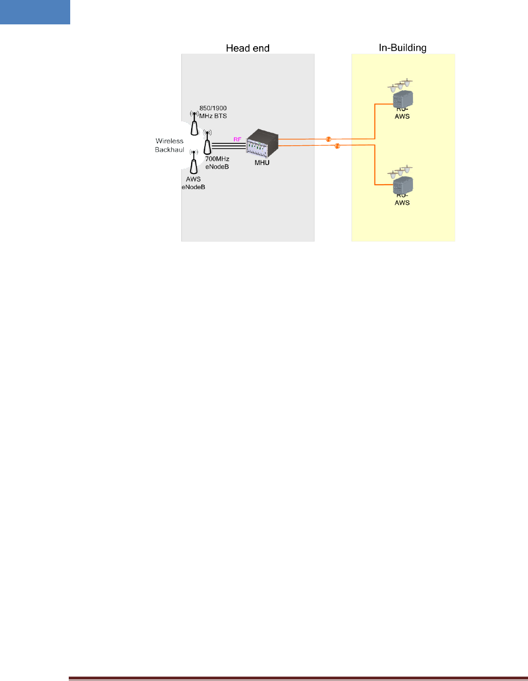
As illustrated in Figure 1-1, Hybrid DAS network is comprised of MHU and RU. Each MHU can support up
to 6 RU’s that can cover up to 500Ksf2 indoor space. An optic cable can be shared between different
carriers by cascading optic connection between MHU systems.
Intelibs, Inc Proprietary and Confidential Page 7
7
Figure 1-1 MHU-RU application
Intelibs, Inc Proprietary and Confidential Page 8
8
2 Product Description
Remote Unit for AWS is a part of the Distributed Antenna System (DAS) to clear RF shadows, to fill
coverage gaps existing among the adjacent cells and to enhance the quality of service of extending
coverage of 2100M AWS.
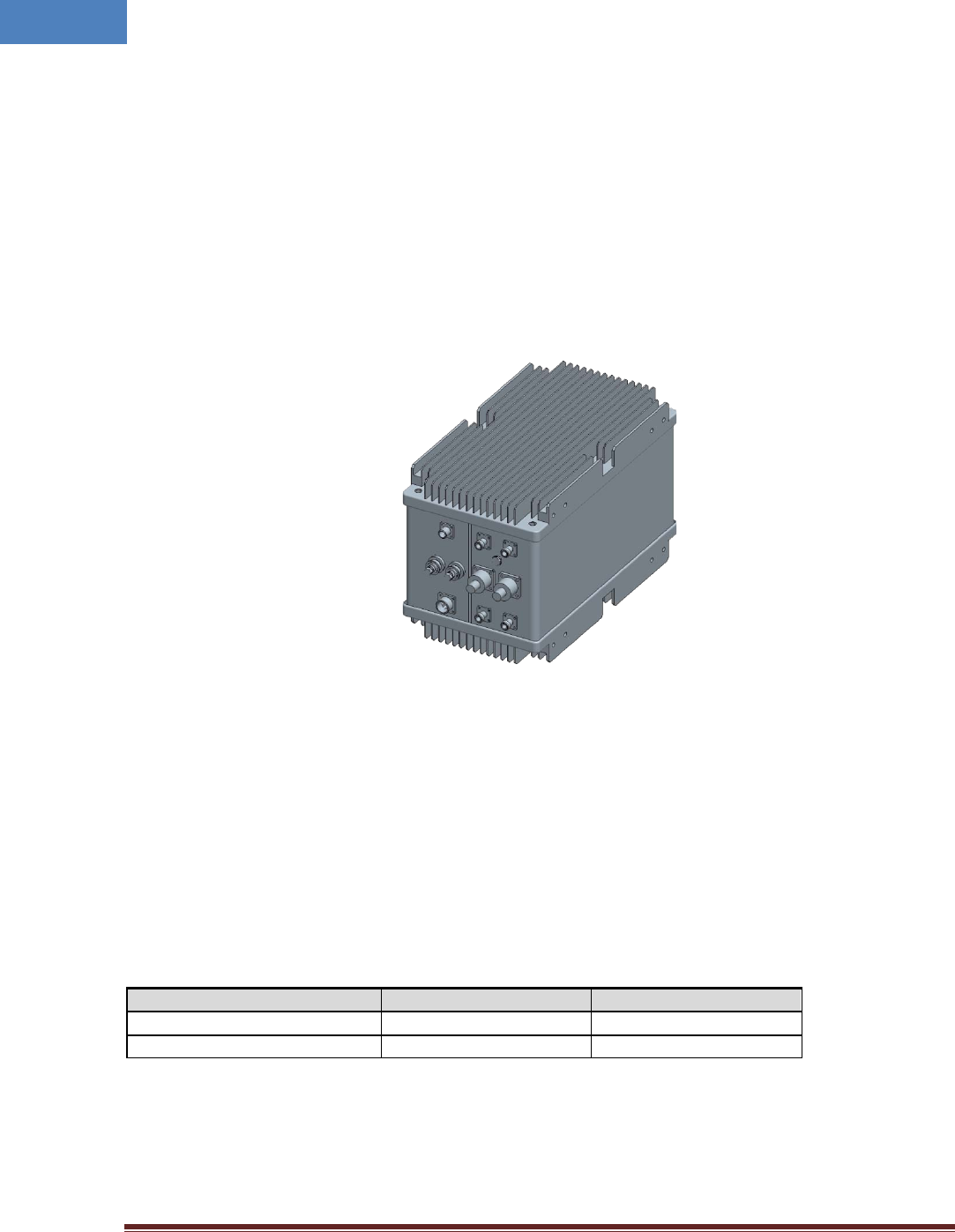
As shown in Figure 2-1, RU is a compact platform with the natural heat convection. As unified form
factor, RU services multiple technologies on a single platform with 2100MHz AWS band operating
frequencies. It can be mounted on the wall or 19” rack. Variety of the service antenna can be used from
short monopole antenna (e.g. rubber ducky antenna) to indoor multi-band ceiling Omni antenna (or
panel antenna).
Figure 2-1 RU system
2.1 Network configuration
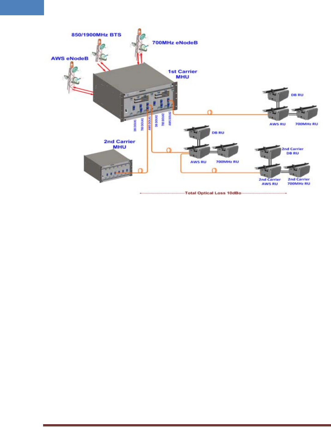
RF signal from a carrier on the 2100MHz AWS band are fed to MHU and directed to fiber optic cable, to
transmit RF signals to remote RU system. MHU can have up to 6 connections with RU systems by
installing DOU cards. A fiber optic cable can be shared between different carriers by cascading optic
connection between MHU systems. Each frequency band signals have their own wavelengths in a single
fiber. Table 2-1 describes those wavelength assignments. Maximum allowed optic loss between MHU
and RU system is 10 dBo.
Table 2-1 Optic wavelength of each frequency band
Frequency band
Downlink Wavelength
Uplink Wavelength
2100MHz AWS
1,310 nm
1,550 nm
Cascading 2nd Carrier
1,350 nm 1,510 nm
RU systems with different operating frequency band can be interconnected via RF cables feed from RU-
AWS system. Typical MHU-RU network diagram is depicted in figure 2-2.
Intelibs, Inc Proprietary and Confidential Page 9
9
Figure 2-2 Typical MHU-RU network diagram
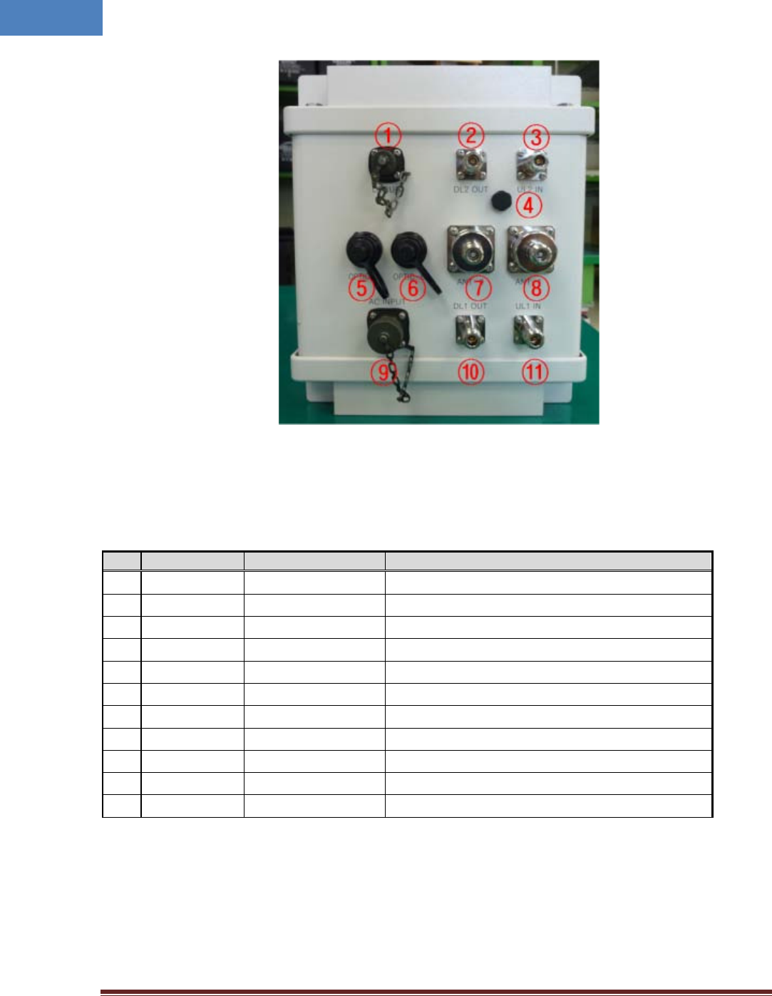
2.2 External interface ports
RU has all interface connections at front side of an enclosure, which includes optic, antennas, power,
and maintenance port. Figure 2-3 shows the front panel of RU system.
Intelibs, Inc Proprietary and Confidential Page 10
10
Figure 2-3 Front view of RU system
Table 2-2 Interface ports
No.
Port
Connector type
Description
1
DEBUG Serial interface for GUI and debugging
2
DL2 OUT N-type Female 850/1900MHz Downlink RF cable connection port
3
UL2 IN N-type Female 850/1900MHz Uplink RF cable connection port
4
Goretex
5 OPTIC-A SC/APC Optic connection port with MHU
6
OPTIC-B SC/APC Optic connection port with 2nd carrier MHU
7
ANT-0 N-type Male AWS MIMO0 Antenna RF cable connection port
8
ANT-1 N-type Male AWS MIMO1 Antenna RF cable connection port
9
AC INPUT MS Connector 110V AC power cable connection port
10 DL1 OUT N-type Female 700MHz LTE Downlink RF cable connection port
11
UL1 IN N-type Female 700MHz LTE Uplink RF cable connection port
Intelibs, Inc Proprietary and Confidential Page 11
11
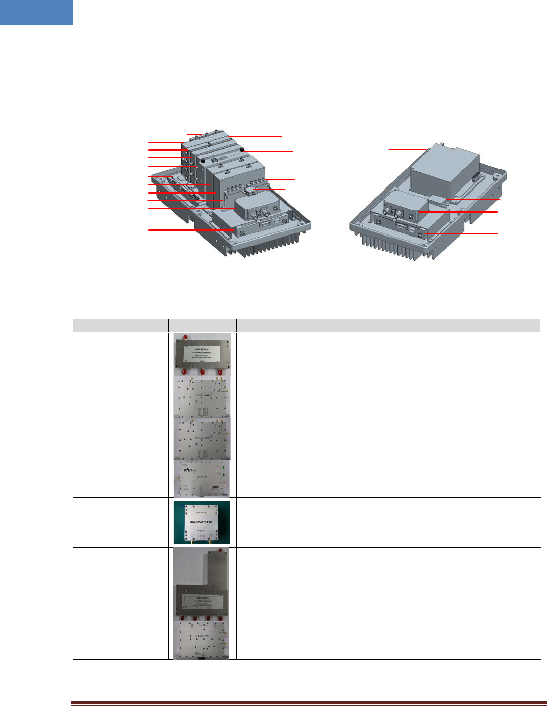
2.3 Modules
RU system is comprised of several internal modules such as combiner, amplifier, optic module, and
filters. Figure 2-4 shows inside of RU system.
Figure 2-4 RU system’s modules
Table 2-3 RU system’s modules
Module
Picture
Description
RFMUX
Divides incoming signals into RF and modem signals, and sends divided
signals to RFBS0/RFBS1 and FSK modem.
RFBS0_AWS
Controls a TX0 path gain, filters downlink frequency band, controls the
TX0 signal’s Crest Factor, and performs the Automatic level Control
(ALC) function. Output of this module is sent to High Power Amp (HPA).
RFBS1_AWS
Controls a TX1 path gain, filters downlink frequency band, controls the
TX1 signal’s Crest Factor, and performs the Automatic level Control
(ALC) function. Output of this module is sent to High Power Amp (HPA).
AWS_SOU
Performs E/O (Electric/Optic) or O/E conversion for downlink and
uplink signals.
AWS_FSK_MODEM
Data modem for out of band communications between MHU and RU
systems. Followings are modem frequencies for downlink and uplink.
- from RU to MHU: 311 MHz
- from MHU to RU: 374 MHz
RRCOM
Combines RX0, RX1, and Modem signals, and sends combined signals
to the AWS_SOU module for E/O conversion.
RRBS0_AWS
Amplifies RX0 signal by low noise high gain amplifier, filters for desired
band frequencies, and controls uplink path gain.
RFMUX
AWS SOU
RRCOM
RRBS1_AWS
RRBS0_AWS
Back Board Ass’y
RFBS1_AWS
RFBS0_AWS
3Way UL
FEU0_AWS
Tx HPA0_AWS
AWS FSK Modem
NMS B’D
3Way DL
PSU(AC/DC)
Noise Filter
FEU1_AWS
Tx HPA1 AWS
10dB Coupler
Intelibs, Inc Proprietary and Confidential Page 12
12
RRBS1_AWS
Amplifies RX1 signal by low noise high gain amplifier, filters for desired
band frequencies, and controls uplink path gain.
HPA_AWS
for MIMO0
Amplifies TX0 signal by 16W (42dBm) high power amplifier, and sends
amplified signal to FE_DUPLEXER_AWS MIMO0 module.
HPA_AWS
for MIMO1
Amplifies TX1 signal by 16W (42dBm) high power amplifier, and sends
amplified signal to FE_DUPLEXER_AWS MIMO1 module.
FE_DUPLEXER_AWS
for MIMO0
Front-end duplex that passes TX0 and RX0 frequencies bands.
FE_DUPLEXER_AWS
for MIMO1
Front-end duplex that passes TX1 and RX1 frequencies bands.
PSU
Converts AC 110V to DC 29V/9V/6.5V/5.5V, and supplies DC converted
voltages to entire modules.
NMS Controller
Monitors status of modules in RU, and controls the configurable
parameters of the RU modules.
Interface BD
Provides interface between NMS and other modules to control and
monitor the modules.
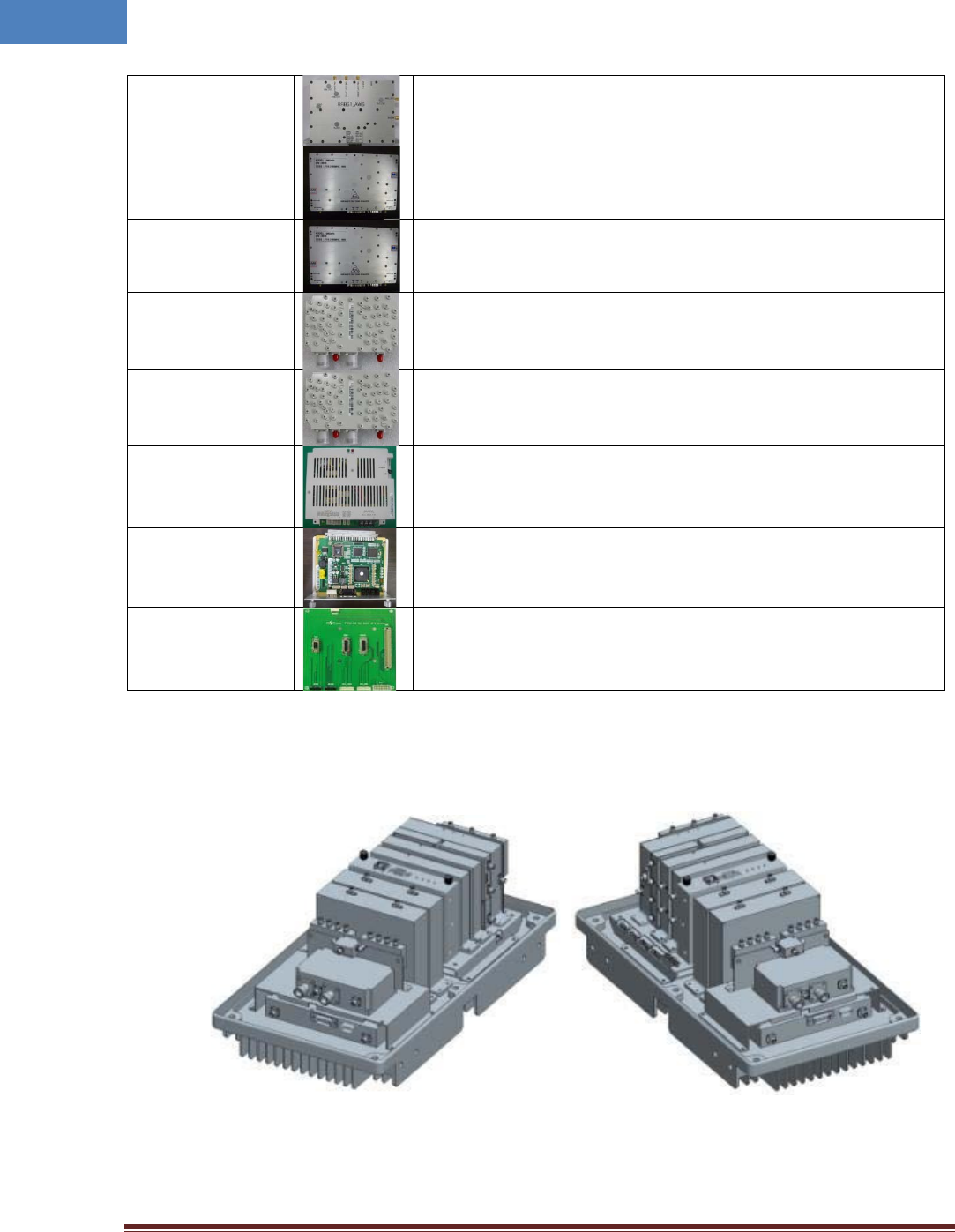
2.4 Mechanical Drawing
Figure 2-5 RF modules
Intelibs, Inc Proprietary and Confidential Page 13
13
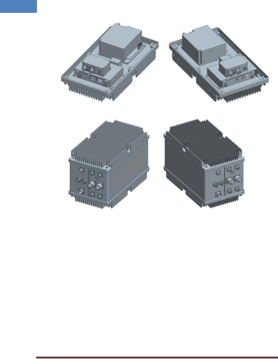
Figure 2-6 PSU module
Figure 2-7 Exterior
Intelibs, Inc Proprietary and Confidential Page 14
14
2.5 Technical Specifications
2.5.1 General specifications
Table 2-4 General Specifications
Specification
Values
Enclosure Type
Cabinet
Dimension (mm) 471.7(H) X 263.4(W) X 304.8(D)mm
Weight
(Kg)
26 Kg
Power Supply 110-120Vac (Tolerance ±10%), 60Hz
Power Connector MS Connecter
RF In/Out Port N Type Female, a side part
Optic Connector Type SC, a side part
Optic Wavelength FWD: 1310nm / RVS: 1550nm AWS DOU 1st Carrier
FWD: 1350nm / RVS: 1510nm AWS DOU 2nd Carrier
Operating Temperature -20℃ ~ 50℃
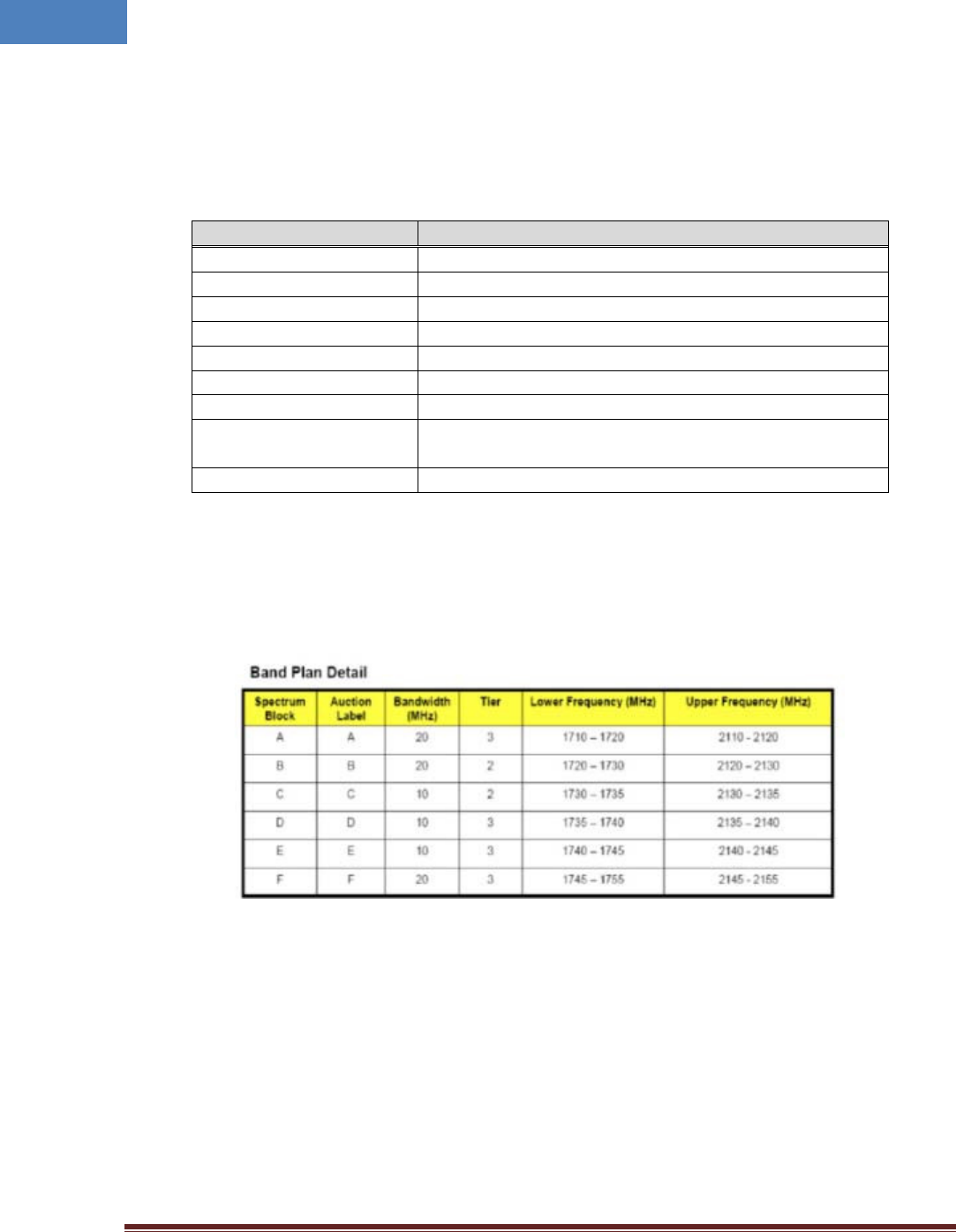
2.5.2 2100 MHz AWS band frequency allocation
Figure 2-11 Frequency allocation of 2100 MHz AWS band

Intelibs, Inc Proprietary and Confidential Page 15
15
2.5.3 RF specifications
Table 2-7 RF specifications
Item Specification Remarks
Tx Frequency
Range Contiguous 25MHz Bandwidth in 2110 ~ 2155MHz
Rx Frequency
Range
Contiguous 25MHz Bandwidth in 1710 ~ 1755MHz
No of Carriers
Supported 2 CH LTE Carrier Max.
FWD Input Power -10 ~ 0dBm/total, -5dBm/total is recommended at MHU IN
FWD Output Power
40dBm/total for 2100MHz RU ANT Port (MIMO0 / MIMO1)
RVS Input Power -45dBm/total max. at RU each ANT Port
RVS Output Power -5dBm/total max. at MHU each Rx Output Port
System Gain FWD: 20dB ~ 40dB RVS:20dB ~ 40dB
FWD Spurious Comply to 3GPP, FCC regulation
RVS Noise Figure 5dB max. @ 40dB Gain Max. Gain
Gain Control Range FWD: 20dB by 1dB Step RVS: 20dB by 1dB Step RU OLC Gain
EVM (Error Vector
Magnitude) 12.5%
Frequency Stability 0.02ppm
Pass-Band Ripple
2dB max. Any CH
System Delay Tx: 5us. Max Rx: 4us. Max Without
optical cable
Tx0-Tx1 Isolation min. 40dBc 700LTE, AWS
Rx0-Rx1 Isolation min. 40dBc 700LTE, AWS
Tx-Rx Isolation 100dB min. @Between RU Tx Output and MHU Rx Output
Impedance
50 Ohm
VSWR 1.5 : 1 max. @ All input/output ports
Optical Wavelength FWD: 1310nm
FWD: 1350nm, 2nd Carrier
RVS: 1550nm
RVS: 1510nm, 2nd Carrier
RF I/O Connector MHU: SMA-type Female RU: N-type Female

Intelibs, Inc Proprietary and Confidential Page 16
16
2.5.4 Power Specifications
Table 2-8 Power specifications
Item
Specification
Rated Input Voltage
110-120V AC, 60 Hz
Permissible range
Tolerance ±10%
Power consumption
250 W, maximum
200 W, typical
Power Connector
MS Connecter

Intelibs, Inc Proprietary and Confidential Page 17
17
3 Installation
3.1 Installation Requirements
Before and during installation, the following should be carefully verified in order to avoid any
problem:
• Faulty Cabling/Connectors: Fiber cable and connectors must be verified prior to plugging
into the RU
• Dirty Connectors and ports
• Faulty Remote Unite (RU) components
• RF source equipment issue
• External RF Interface problem such as antenna port
The following guidelines are required when the Headend unit is installed on the 19” rack:
• Locate the equipment with the space for the sufficient airflow to prevent build-up from
the overheating. Do not compromise the amount of airflow required for safe operation of
the equipment.
• Verify the power connection and Fiber cables prior to turning on the systems.
WARNING: Equipment loading must be verified prior to mounting the equipment on the wall or 19” rack.
3.1.1 General Safety Precautions
The following precautions apply to the RU:
• The units have no user-serviceable parts. Faulty or failed units are fully replaceable through
Intelibs.
• When the Fiber cable is connected to the equipment, the connectors must be free from the dust
and connected according to the cable manufacturer’s instructions. (WARNING: For the safety,
DO NOT conduct eye-contact at the connector ends of the fibers or the port of the MHU and RU
unless equipped with protection goggle. Invisible infrared radiation may be present at the front
panel of the MHU and RU. Do not remove the fiber port dust caps unless the port is going to be
used. Do not stare directly into a fiber port.)
Intelibs, Inc Proprietary and Confidential Page 18
18
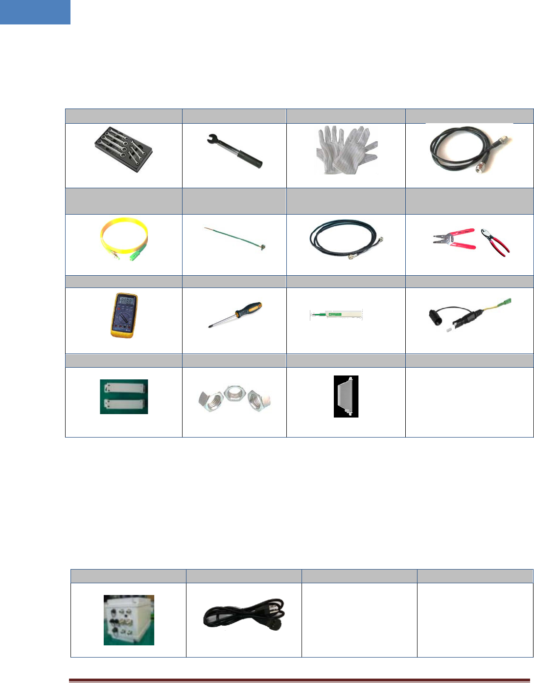
3.2 Installation Tools
Table 3-1 Installation tools
Torque Wrench Torque Wrench ESD Gloves 4ea of 5m SMA cable
FC/APC-SC/APC
Optic Fiber, 10m Ground wire line 2ea of ANT RF Cable Wire Stripper & Cutter
Digital Multi-meter
Screw Driver
Optic connector cleaner
Optic cable, 3m SC/APC
Mounting bracket
Fixing nuts RU ANT for AWS, 2ea
Wall mount bracket, 1 set
3.3 Item Check List
Check that all the following items have been included with the box delivered. If anything is missing,
please contact Intelibs.
Table 3-2 Item check list
RU-AWS
AC power cable
RU equipment: 1 ea
AC power cable:
1.5m, 1 ea
Intelibs, Inc Proprietary and Confidential Page 19
19
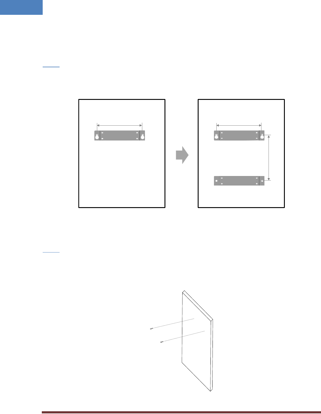
3.4 Mounting
RU supports wall mount. The following diagrams illustrate the methods for mounting RU on a typical
wall.
• Mark the upper position by using the wall mount bracket for upper position.
Step 1
• Mark the lower position by using the wall mount bracket for lower position.
Figure 3-1 Mark the installation position
• Screw two bolts to the upper positions.
Step 2
Figure 3-2 Install the upper bolts
327 mm
(12.87”)
327 mm
(12.87”)
332 mm
(13.07”)
Intelibs, Inc Proprietary and Confidential Page 20
20
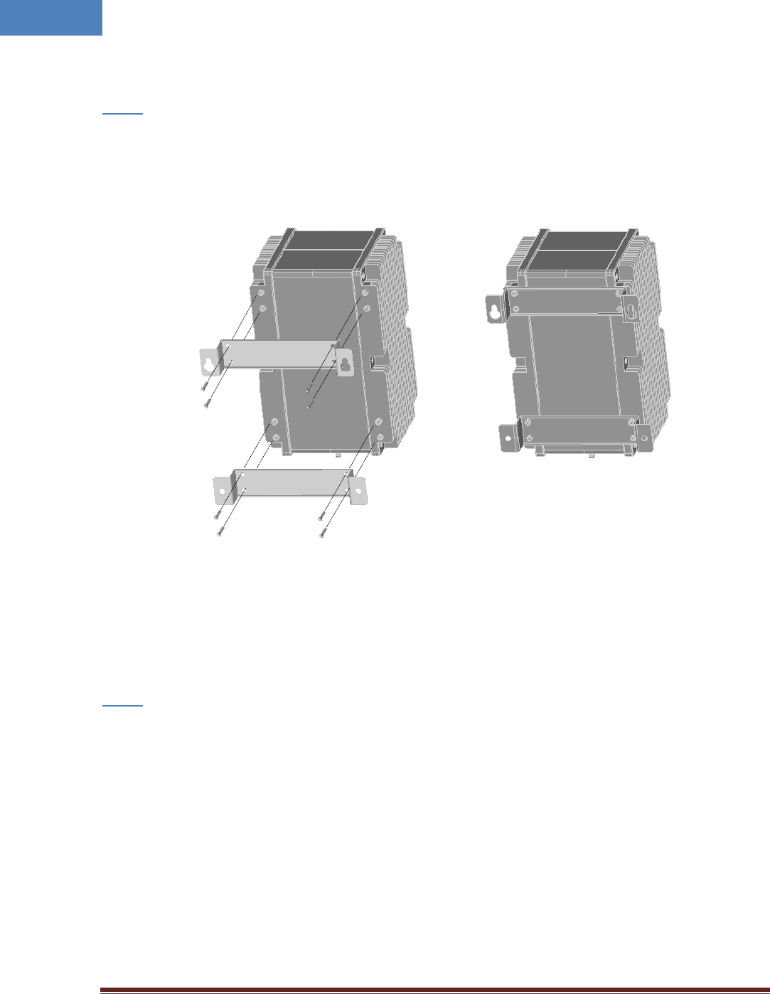
• Install the wall mount brackets as figure below. The wall mount brackets and the bolts are
provided along with RU system.
Step 3
Figure 3-3 Install the wall mount bracket
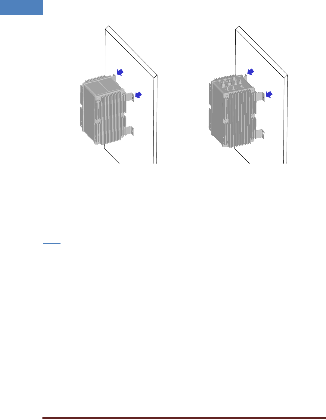
• Insert upper bracket hole into installed bolts on the upper positions.
Step 3
Mounting bracket RU with bracket
Intelibs, Inc Proprietary and Confidential Page 21
21
Figure 3-4 Hanging the upper bracket on the installed bolt
• Screw two bolts to the lower positions.
Step 4
Interface ports on the bottom Interface ports on the top
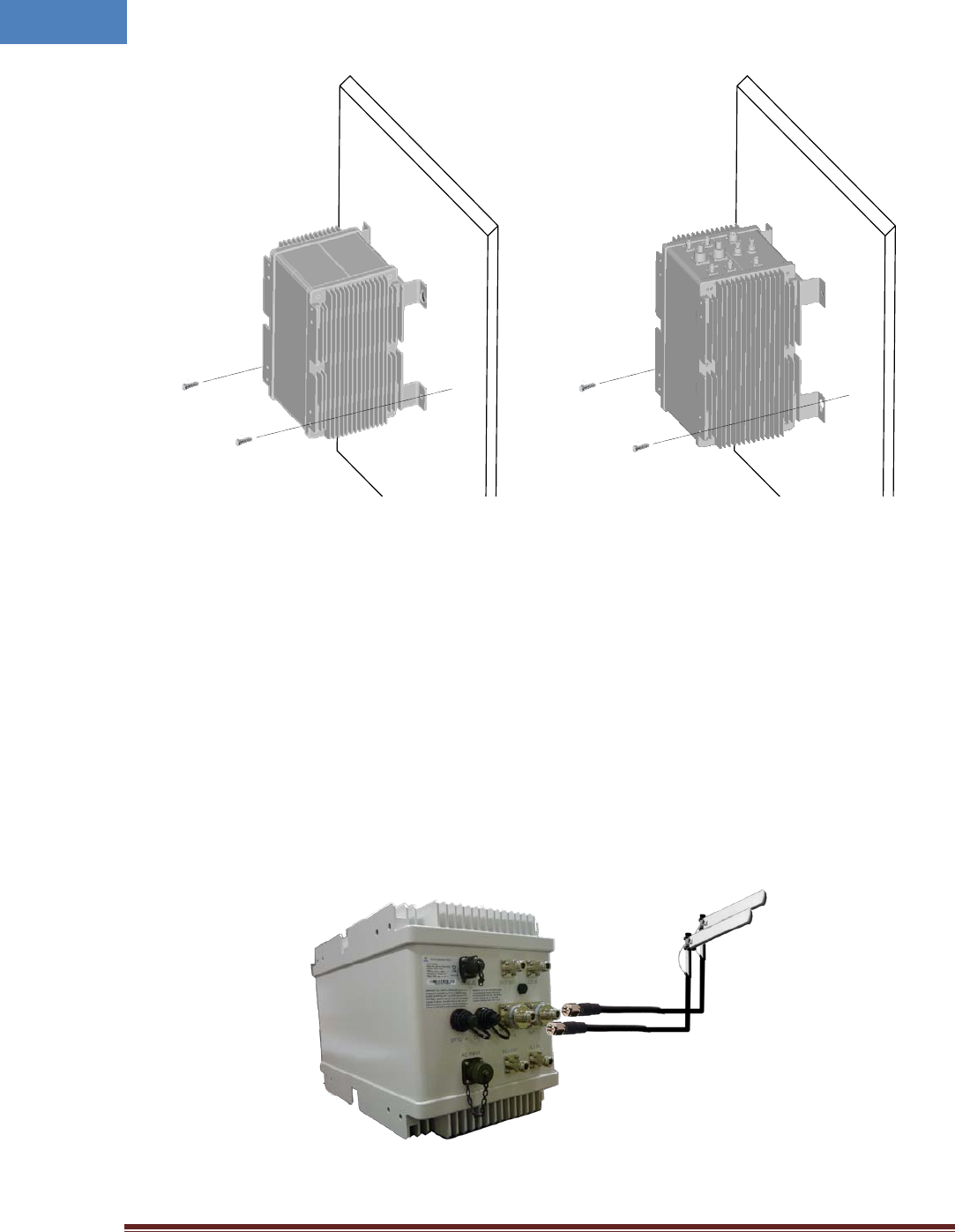
Intelibs, Inc Proprietary and Confidential Page 22
22
Figure 3-5 Install the lower bolts
3.5 Link (Donor) Antenna
RU has two antenna ports. The one is for Cellular/LTE-main/AWS-main channel, the other is for PCS/LTE-
MIMO/ASW-MIMO channel. Connect N-type female antenna cable to the desired antenna port, “ANT-0”
or “ANT-1”, as Figure below.
Figure 3-6 Link Antenna connection
Interface ports on the bottom Interface ports on the top
AWS Main
AWS MIMO
Intelibs, Inc Proprietary and Confidential Page 23
23
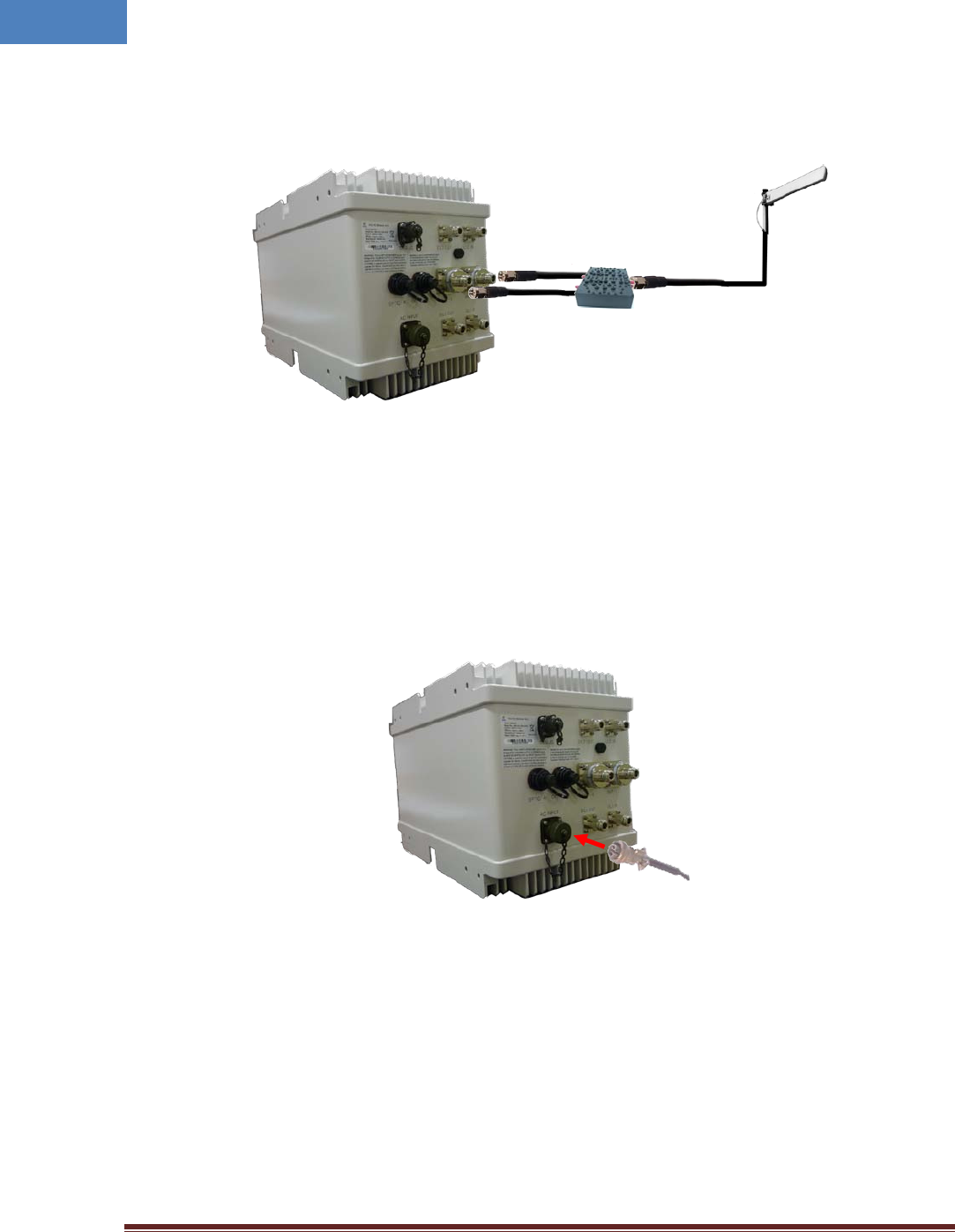
The duplex can be used which combine two port signals into one.
Figure 3-7 Link Antenna connection with Duplex
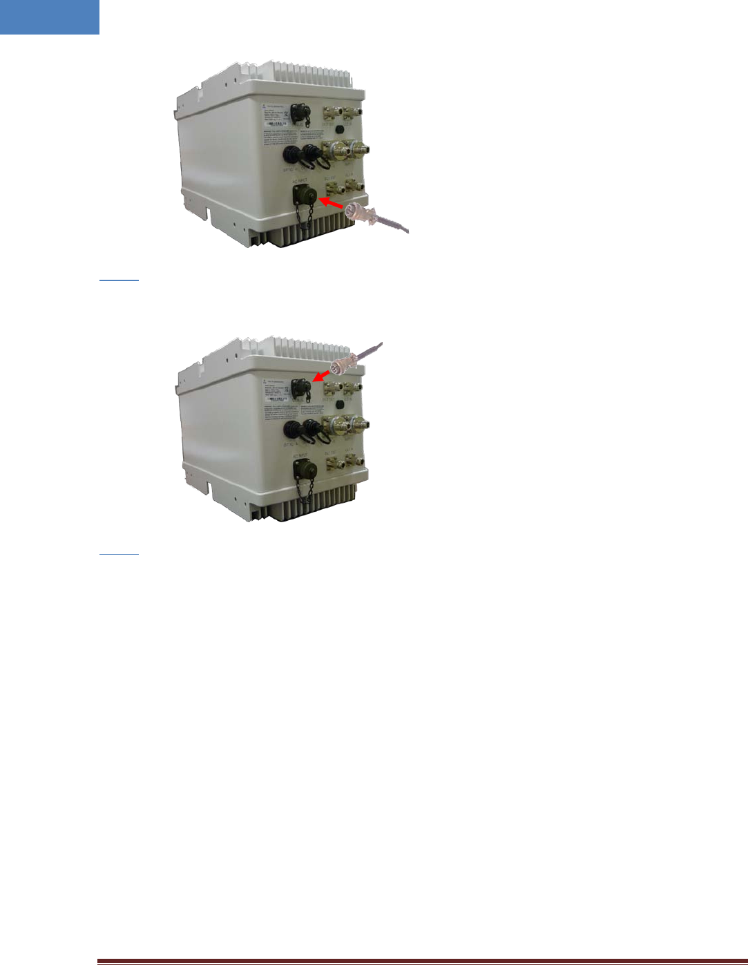
3.6 Power cable
Connect MS connector-type power cable to the “AC-INPUT” port. When connecting the end terminal,
align connector at latch and hole position as marked in red circle in Figure below.
Figure 3-8 Power cable connection
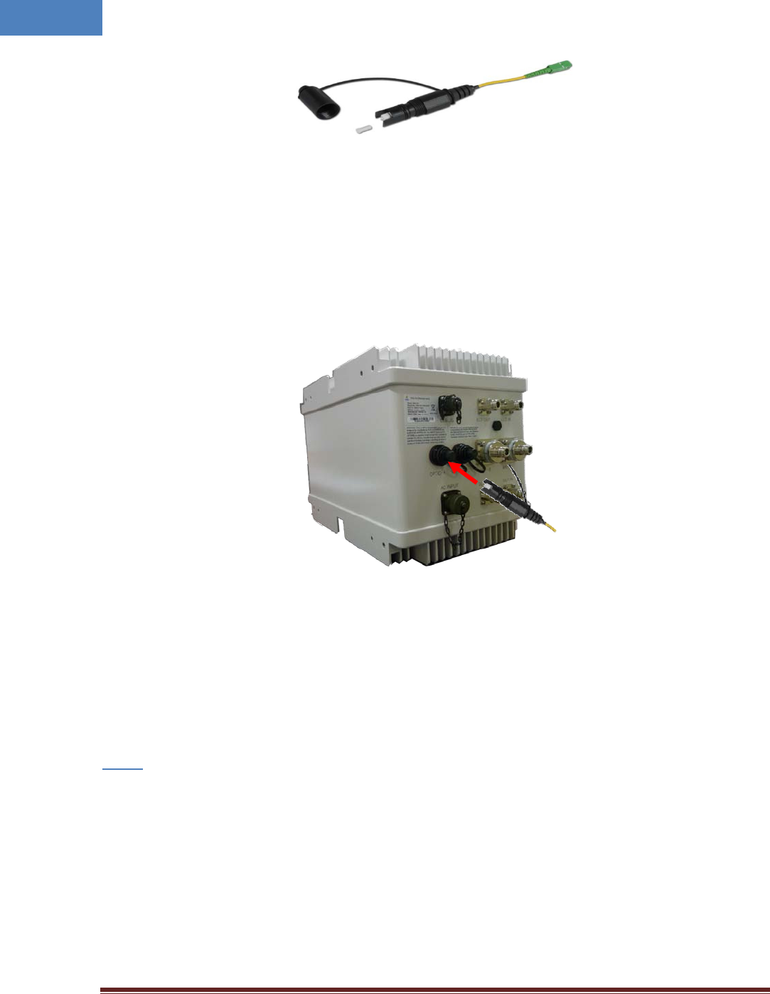
3.7 Optic cable
RU provides two optic ports. The one is for main channel, the other is for cascading purpose. The
connector used for optic interface is an OSP (Outside Plant) hardened SC/APC connector. This
ruggedized connector is compatible with industry standard OSP terminals. Figure 3-9 shows OSP optic
cable supplied with RU system.
Duplex
AWS Main
AWS MIMO
Intelibs, Inc Proprietary and Confidential Page 24
24
Figure 3-9 OSP hardened SC/APC optic cable
Connect ruggedized OSP side optic connector to the desired optic port on RU, “OPTIC-A” as Figure below.
When connecting the optic connector, align the connector at latch position, then plug in and rotate
clockwise tightly.
Figure 3-10 Optic cable connection
3.8 RF power setting
3.8.1 Down Link power setting
• Connect the power cable to RU to turn on the system.
Step 1
Intelibs, Inc Proprietary and Confidential Page 25
25
• Connect USB cable to manage RU through Laptop.
Step 2
• Run LMT application as the procedure described in 2.8.1.1.
Step 3
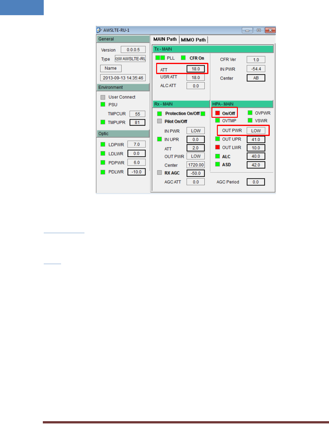
• Adjust parameters as follows:
① Decrease the DL “USER ATT” to 30dB(Minimum gain) and verify that antenna is connected at
antenna port of RU properly.
② Press the “HPA On/Off” button to turn HPA on.
③ Monitor the output power level from “ OUT PWR” parameter, and tune up “USR ATT” to set
the proper output power level.
Intelibs, Inc Proprietary and Confidential Page 26
26
3.8.2 Up Link power setting
• Follow same steps as Downlink power setting.
Step 1 – Step 2
• Run LMT application as the procedure described in 2.8.1.1.
Step 3
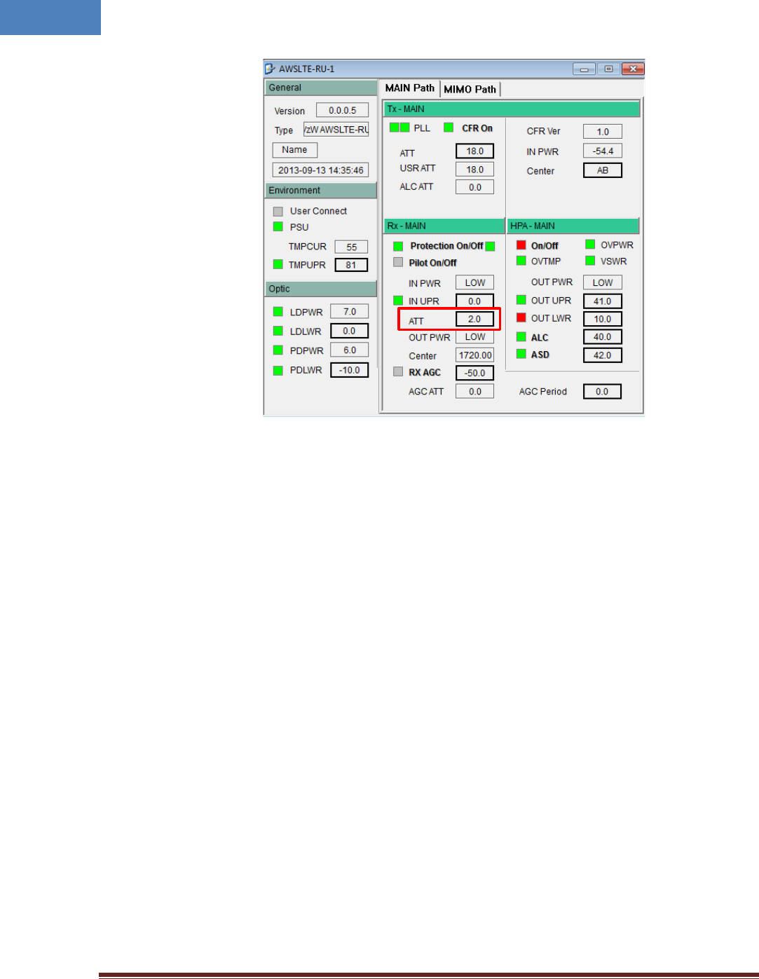
• Adjust parameters as follows:
① Use the “ATT” to control Uplink gain.
② Uplink gain is very important parameter because uplink is connected to RF source of BTS. If
you have wrong uplink gain set, BTS receiver sensitivity may be degraded due to improper
uplink gain.
③ Try to minimize uplink gain with mobile Tx power.
❶
❷
❸
Intelibs, Inc Proprietary and Confidential Page 27
27
4 Configuration and Maintenance
RU can be configured in three ways via remote internet connection or local serial port connection.
• SNMPv3 interface through the internet
• Web interface through the internet
• Local management interface through the internet, serial connection, and Bluetooth
Master Unit is a remote management system that provides SNMP v3 and Web interface, and maintains
all functions of optical DAS system including configurations, monitoring, and real time alarm reporting.
LMT (Local Management Terminal) is local management interface through IP network, serial interface,
and Bluetooth.
The configuration and maintenance for RUs are performed by accessing MHU system through any
interfaces provided by MHU.
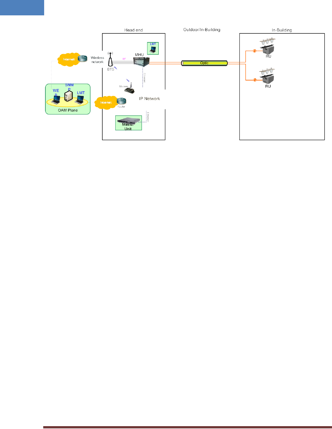
Figure below describes a typical DAS management system network and the entities.
❶
Intelibs, Inc Proprietary and Confidential Page 28
28
Figure 4-1 DAS management network and entities
Intelibs, Inc Proprietary and Confidential Page 29
29
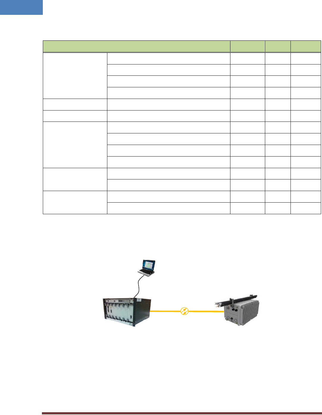
Table 4-1 DAS management entities and their functions
Functions SNMPv3 Web LMT
On-site Installation
Serial interface o
IP address assignment o
ID assignment (for Remote Unit) o
System Password o
System Registration System Registration/Unregister o
Site/Location setting DAS system’s site and location information o
Remote/Local
management
Capture and restore the configuration o
Parameters settings and retrieval o o o
F/W upgrade o o
Alarms o o o
Alarms
Alarm history o
Current Alarm o o o
User management
Creation & Deletion of users o o
Password management o o o
Figure 4-2 MHU/RU network
Figure 4-2 is an example of DAS network using LMT to configure DAS system. Following sections
describes how to configure and manage RU system using LMT via serial/LAN connection or using Web
Interface via Internet.
MHU
RS-232/LAN
LMT
RU
Intelibs, Inc Proprietary and Confidential Page 30
30
4.1 Configuring RU using LMT
If one of serial or LAN connection has been established, LMT is ready to start. Launch the Local
Management application by clicking the icon “Cherry” and follows the steps below.
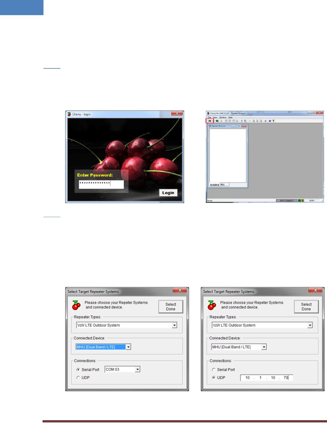
• Launch the application “Cherry”.
Step 1
• Enter the password, click “Login”.
• Click “Connect” icon on the left top corner of window or click [File]-[connect] menu.
• Select the connection parameters as follows:
Step 2
- Repeater Types: VzW LTE Outdoor System
- Connected Device: MHU [Dual Band / LTE]
- Connections
o Serial Port: The port number established via serial interface or
o UDP: IP address for the Ethernet interface
• Click “Select Done” button.
Intelibs, Inc Proprietary and Confidential Page 31
31
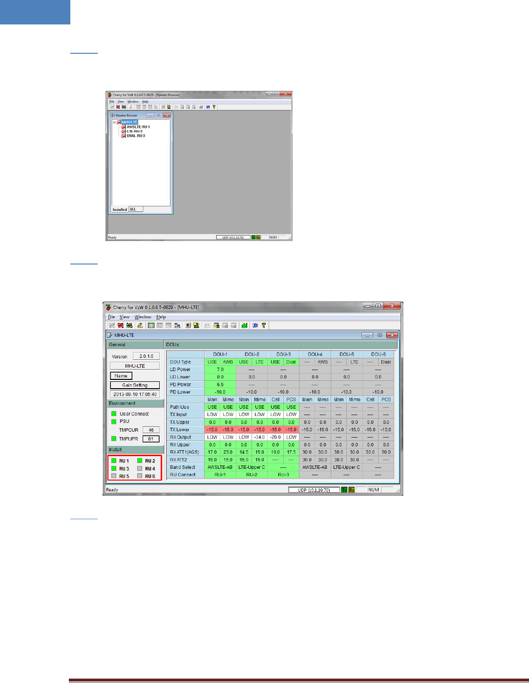
• If “Repeater Browser” window appears, click MHU-LTE system.
Step 3
• Click any place inside of “Install” panel area.
Step 4
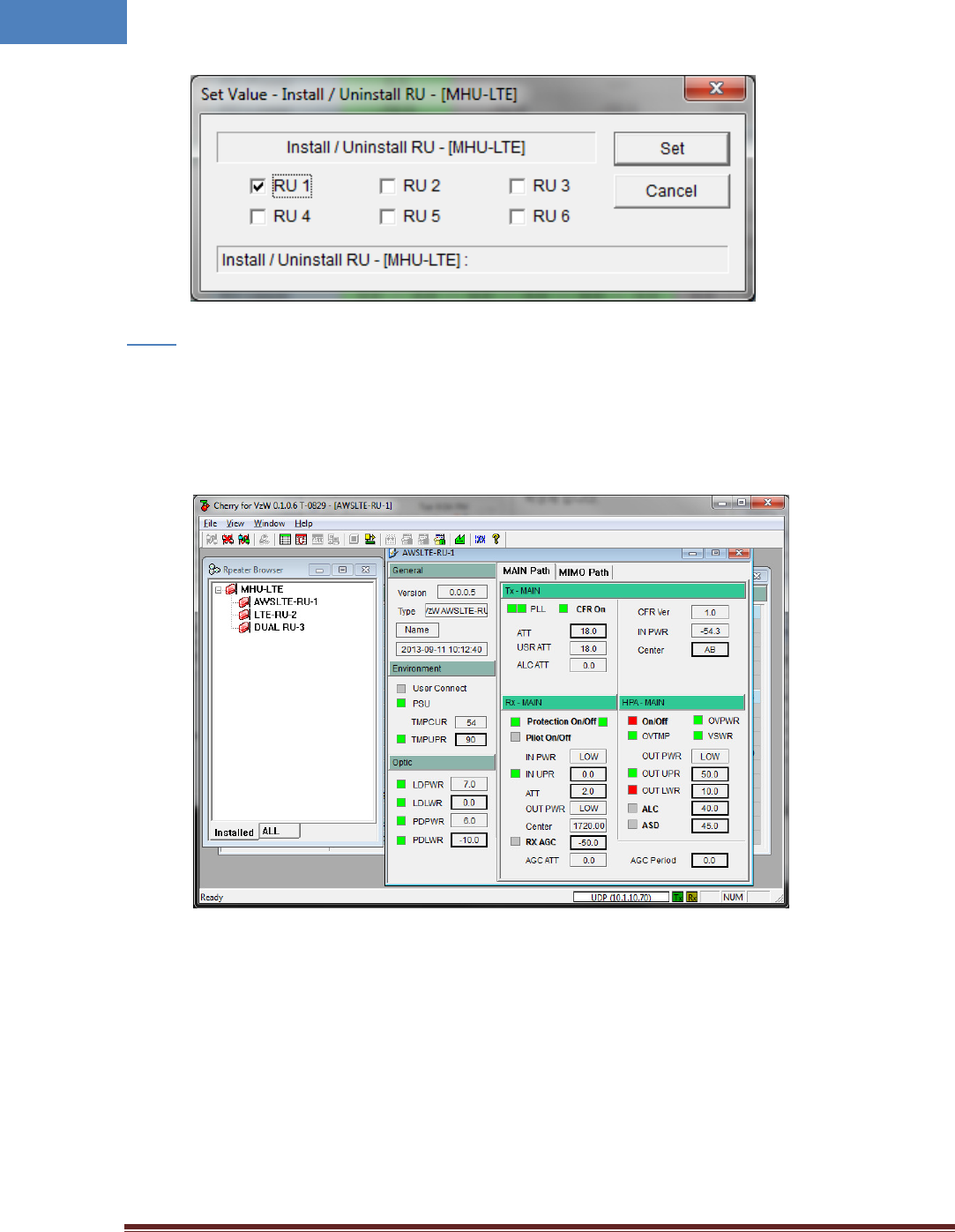
• At “Install / Uninstall RU – [MHU-LTE]” window, click the RU systems that has been installed
according to MHU’s port number that is connected via optic cable.
Step 5
• Then click “Set” button.
Intelibs, Inc Proprietary and Confidential Page 32
32
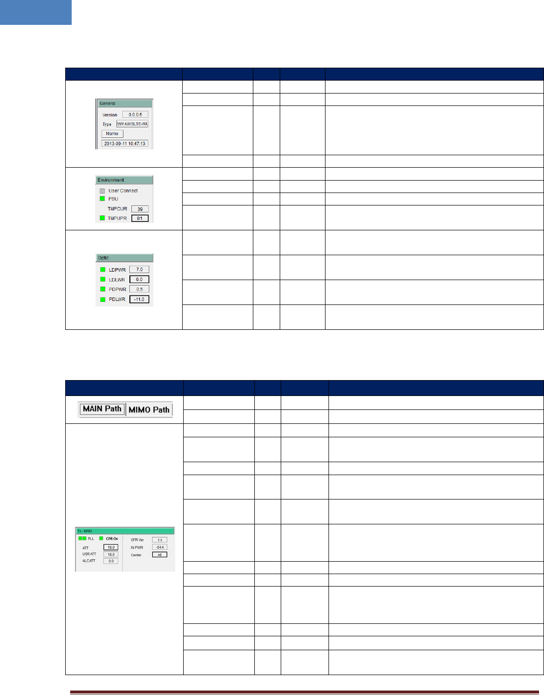
• If RU is installed properly, the RU system can be found under the MHU system in “Repeater
Browser” window.
Step 6
• At “Repeater Browser” window, click the DAS system to be managed, then the selected DAS
system’s control window will pop up.
If connection is established successfully, then all parameters of RU system can be read/set by LMT
terminal, and all status information can be reported to LMT. RU’s status and parameters controllable by
LMT are described in Table 4-2, 4-3, 4-4, and 4-5.
Intelibs, Inc Proprietary and Confidential Page 33
33
Table 4-2 General/Environment/Optic
Status group
Parameters
LED
Settable
Description
Version
Firmware Version of the DAS system
DAS Type The type of the DAS system
Name
√
Sets following information of the DAS
- Name
- Model Number
- Serial Number
Time/UpTime Current time or Up-time
User Connect
√
Connection status with the DAS
PSU
√
Status of Power Supply Unit
TMPCUR
Current chassis temperature of the DAS system
TMPUPR √ √ Sets temperature upper limit, and display its value
and alarm status.
LDPWR
√
Current output power of LD (Laser Diode) of optic
module connected to RU.
LDLWR √ √
Sets the lower limit of output power of LD, and
display its value and alarm status.
PDPWR √ Current input power of PD (Photo Detector) of
optic module connected to RU.
PDLWR √ √ Sets the lower limit of input power of PD, and
display its value and alarm status.
Table 4-3 Tx-MAIN/MIMO
Status group Parameters LED
Clickable Description
MAIN Path
Selects MAIN channel
MIMO Path
Selects MIMO channel
PLL
√
PLL’s Alarm status
CFR ON √ √ ON/OFF status and control of CFR (Crest Factor
Reduction) function
CFR Ver. Version of CFR function currently working
ATT √ Sets ATT value to control downlink Gain.
ATT = USR ATT + ALC ATT
USR ATT Used for downlink Auto Gain Control and fine
tuning of gain.
ALC ATT
Downlink ALC (Automatic Level Control)
attenuation value. Available when ALC function is
activated.
IN PWR
Downlink input power from MHU
Center
√
Sets a center frequency of downlink AWS band.
TC ATT √
Displays downlink temperature compensation
attenuation value, and enable/disable downlink
temperature compensation.
HPA On/Off √ √ Enable/disable downlink HPA (High Power Amp).
OUT PWR
Downlink output power
OUT UPR √ √
Sets upper limit of downlink output power, and
displays its value and alarm status
Intelibs, Inc Proprietary and Confidential Page 34
34
OUT LWR √ √ Sets lower limit of downlink output power, and
displays its value and alarm status
ALC √ √ Sets ALC (Automatic Level Control) function’s
activation level, and enable/disable ALC.
ASD √ √ Sets ASD (Automatic Shut Down) function’s
activation level, and enable/disable ASD.
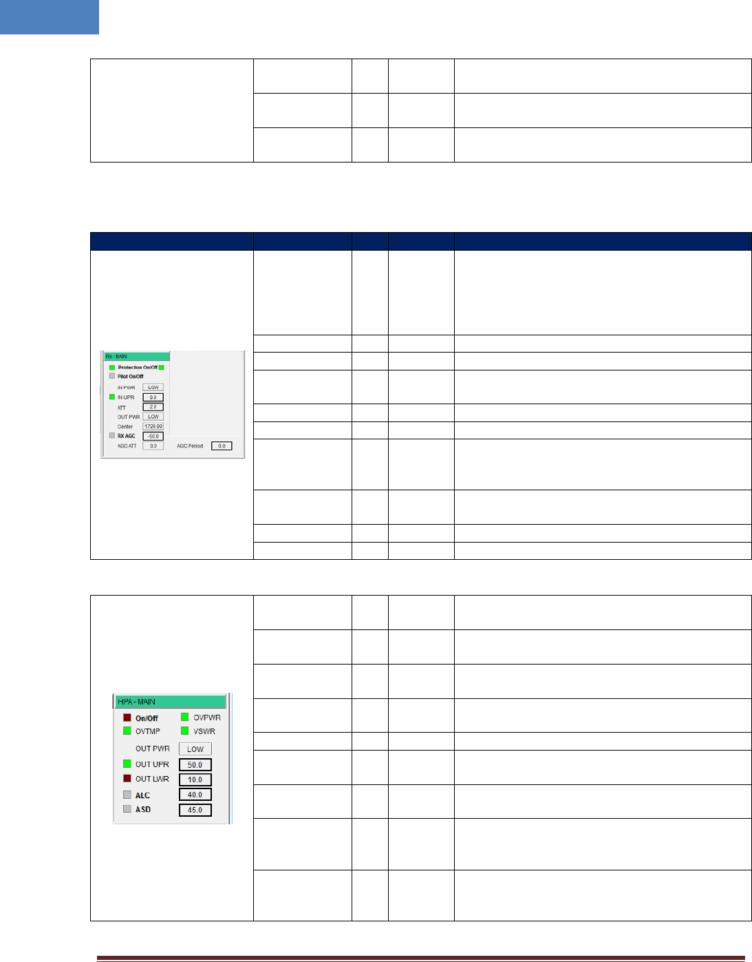
Table 4-4 Rx-MAIN/MIMO
Status group
Parameters
LED
Clickable
Description
Protection
On/Off √ √
Enable/disable uplink Protection function. In
order to protect RU system from unexpected
uplink high input power. If uplink input signal is
higher than “IN UPR” level, RU system is shut
downed and the LED color turns to red color.
Pilot On/Off
√ √ Enable CW signal. It is used for uplink gain setting.
IN PWR
Uplink input power
IN UPR √ √ Sets upper limit of uplink input power, and
displays its value and alarm status
ATT √ Sets uplink attenuation, and displays its value.
OUT PWR Uplink output power
Center
Indicates a frequency of pilot signal, and this
value is changed automatically as downlink center
frequency changed.
RX AGC √ √ Enable uplink path AGC (Automatic Gain Control)
function, and sets its level.
AGC ATT
Attenuation value of uplink path AGC function
AGC Period Time period of uplink path AGC function
Table 4-5 HPA-MAIN/MIMO
On/Off √ √ Enable downlink HPA (High Power Amplifier)
function, and indicates its status.
OVTMP √ Indicates current alarm status of HPA’s over-
temperature.
OVPWR √ Indicates current alarm status of HPA’s over-
Power.
VSWR √ Indicates current alarm status of HPA’s VSWR
(Voltage Standing Wave Ratio).
OUT PWR
Indicates HPA’s output power level.
OUT UPR √ √ Indicates current alarm status of HPA’s output
power upper limit, and sets upper limit value.
OUT LWR √ √ Indicates current alarm status of HPA’s output
power lower limit, and sets lower limit value.
ALC √ √
Indicates ALC (Automatic Level Control) function’s
current on/Off status, and sets ALC activation
level.
ASD √ √
Indicates ASD (Automatic Shut Down) function’s
current on/Off status, and sets ASD activation
level.
Intelibs, Inc Proprietary and Confidential Page 35
35
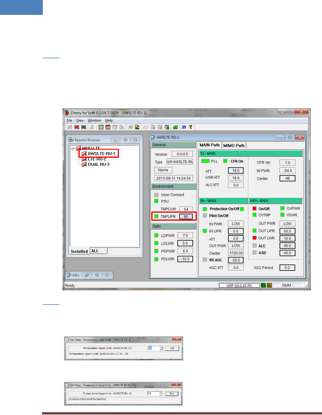
4.2 Example: Setting the Temperature Upper Limit
Following is one example of LMT operation which sets the upper limit of RU chassis’ temperature.
• At “Repeater Browser” window, click the DAS system to be managed, then the selected DAS
system’s control window will pop up.
Step 1
• Click the temperature upper limit box which is on the right side of “TMPUPR”. A number in the
box represents current upper limit of chassis’ temperature.
• Select TMPUPR value by clicking up/down button or enter temperature upper limit. Then click
“Set” button.
Step 2
• The result of operation displays at the bottom of the window.
Intelibs, Inc Proprietary and Confidential Page 36
36
• Click close button on the upper right corner of the window to exit the command window.
The small color box on the left side of “TMPUPR” represents current status of upper limit of RU
chassis’ temperature. If the box is GREEN, operating status is in normal condition. If the box is
RED, “TMPUPR” alarm occurred and remains.
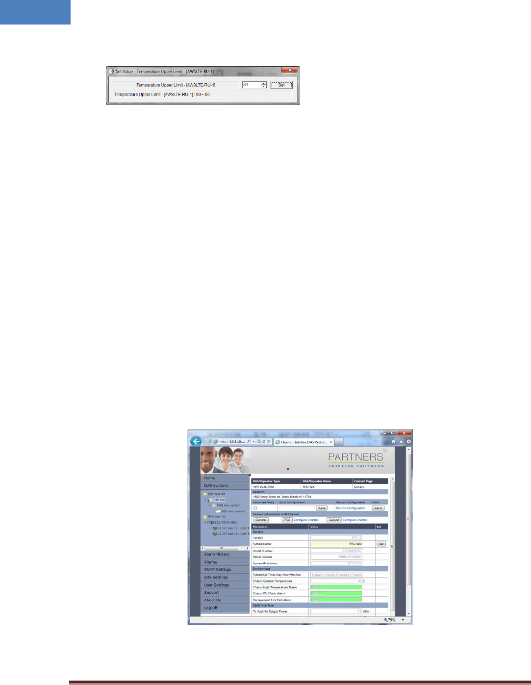
4.3 Web interface
Master Unit provides comprehensive management of the Intelibs optical DAS systems via Web GUI.
Master Unit provides following functions for Web clients:
• Hierarchical view of the DAS systems
• Alarms histories
• Current Alarms
• SNMP agent settings
• Site and location information settings
• Web user settings
• Capture and restore the configuration of the DAS systems
• Parameter settings of the DAS systems
The web GUI is divided into two parts, a menu panel and a Parameter view panel. The menu panel is on
the left side of main window, and the other side is the parameter view panel as shown in Figure 4-3.
Figure 4-3 Web GUI
Menu Panel Parameter view Panel
Intelibs, Inc Proprietary and Confidential Page 37
37
The menu panel contains following menu functions:
• Home: Introductions of Intelibs, Inc, and brief introduction of GUI usage.
• DAS systems: Hierarchical view of registered DAS systems.
• Alarm history: Alarm log of all registered DAS systems.
• Alarms: Current alarms of all registered DAS systems.
• SNMP settings: SNMP environment settings such as trap IP, community, V3 user, etc.
• Site settings: Assign site and location information to each registered Das systems.
• User settings: Add/delete web user and change user’s password
• Support: Intelibs’ support information.
• About us: Redirect to Intelibs’ web page.
• Log Off: Logging off current user’s session.
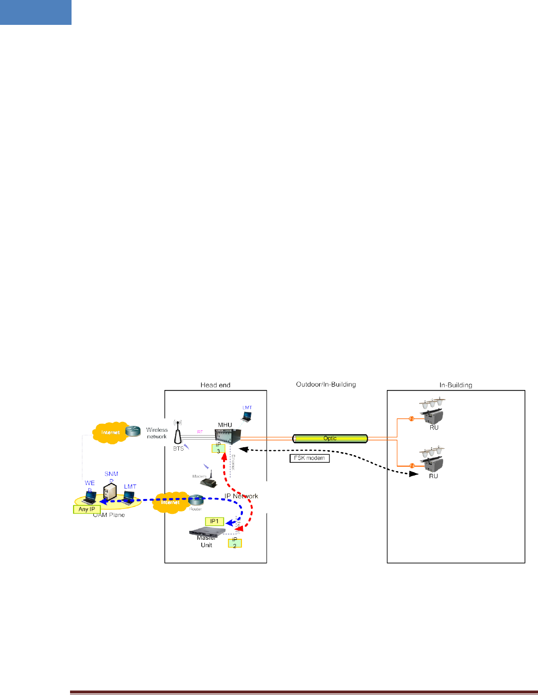
Before using web interface, followings should be assigned and set correctly:
• Master Unit’s IP address
• MHU system’s IP address
• Master Unit’s IP address on MHU system
Figure 4-4 shows web interface flow over IP network.
Figure 4-4 Web interface flow
If IP network connection is established successfully, then parameters of RU can be set by Web browser,
and all status information can be reported to Web browser.
Following is one example of Web operation which sets the upper limit of RU chassis’ temperature.
Intelibs, Inc Proprietary and Confidential Page 38
38
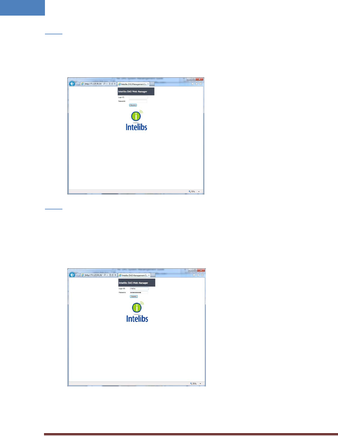
• Open Web browser such as Internet Explorer or Chrome.
Step 1
• Enter Master Unit’s IP address that is assigned for Web interface. Usually the IP address is global
IP or private IP if web client is on the same network where Master Unit is.
• Enter Login ID and Password. (Please contact Intelibs for login ID and password)
Step 2
The web interface provides two level user access, privileged or not. Privileged users can retrieve
and change the advanced parameters that control the DAS system. For example, “TMPUPR”
parameter is an advanced parameter that requires privileged user login.
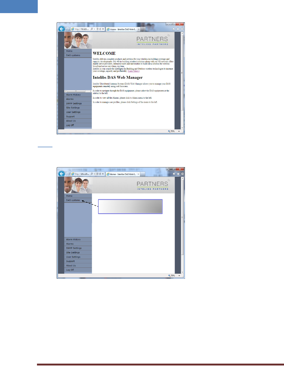
• If ID/PWD matches, Web interface goes to Home page.
Intelibs, Inc Proprietary and Confidential Page 39
39
• Click “DAS systems” menu box to see the Hierarchy view of DAS systems.
Step 3
Clicking this menu box expands
hierarchical tree view of the registered
DAS systems
Intelibs, Inc Proprietary and Confidential Page 40
40
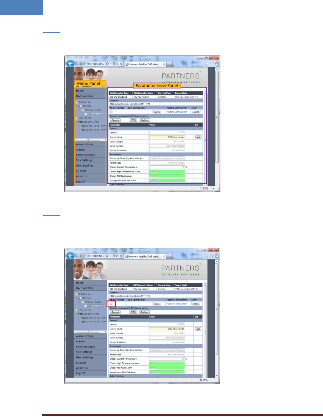
Step 4
• Select a DAS system to control and monitor at the hierarchy view.
Step 5
• Select “Advanced Mode” check box to display advanced parameters, for example “Chassis High
Temperature Alarm Threshold” in the parameter view panel.
Intelibs, Inc Proprietary and Confidential Page 41
41
Step 6
• Enter numbers for “Chassis High Temperature Alarm Threshold”. Then click “Set” button.
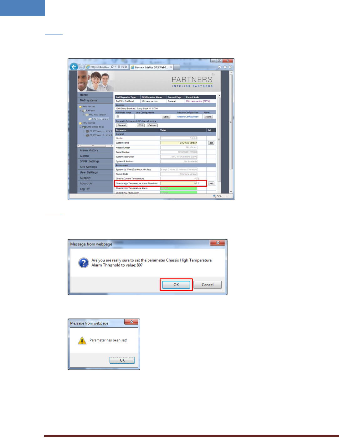
Step 7
• If confirmation window pops up, click “OK” button to confirm changing the parameter value.
• Then result window will pop up.
The column “Chassis High Temperature Alarm” represents upper limit of RU chassis’
temperature. If the value box is GREEN, operating status is in normal condition. If the box is
ORANGE, this indicates “TMPUPR” alarm is turned on.
Intelibs, Inc Proprietary and Confidential Page 42
42
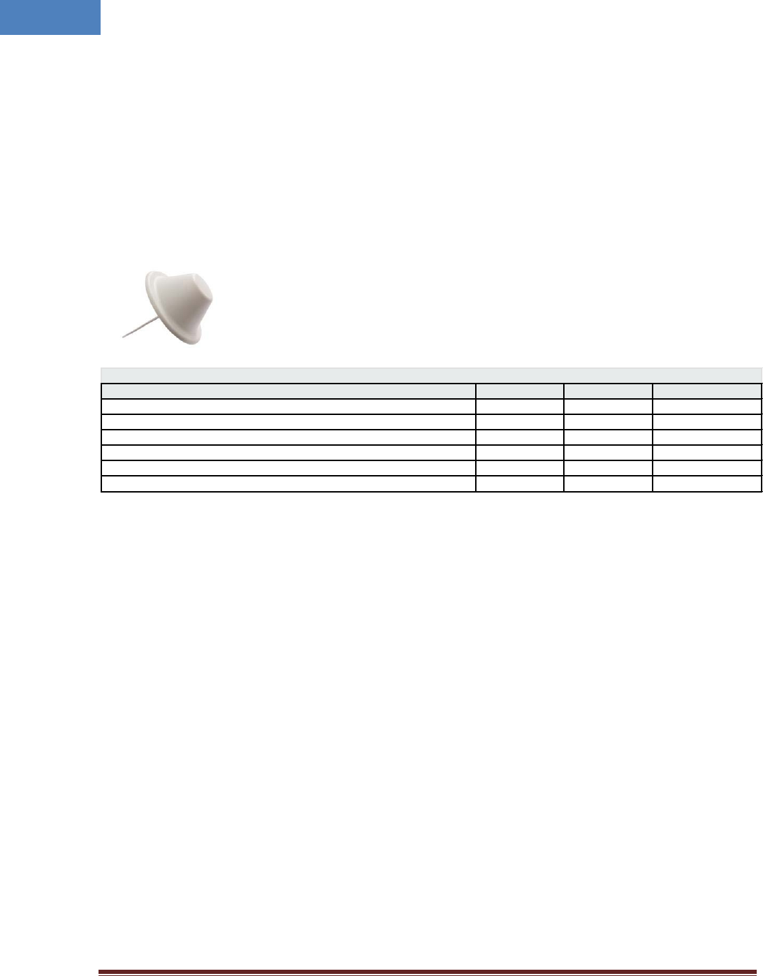
5 Appendix I. Ancillary Devices – Antenna, Cable and other Passive
Device
Intelibs does not provide the ancillary device, however the following or equivalent devices are
recommended:
• Recommended Antenna:
o Commscope
Ele ct rica l Specifica t ions
Freque ncy Ba nd, MHz
6 9 8 –8 0 0
800–9 6 0
1 7 1 0 –2 7 0 0
Gain, dBi
1.5
1.5
5.0
Beam w idt h, Horizont al, degrees
360
360
360
VSWR | Ret urn Loss, dB
1.8 | 10.9
1.5 | 14.0
1.5 | 14.0
I nput Power per Port, m axim um , wat ts
50
50
50
Polar izat ion
Vert ical
Vert ical
Vert ical
I m pedance
50 ohm
50 ohm
50 ohm
• Coaxial Cable:
o RG142 or equivalent coaxial cables
• Fiber Cable:
o SC/APC optical cable

Intelibs, Inc Proprietary and Confidential Page 43
43
Limited Warranty
I nt elibs, I n c ( “I n t elibs” ) offers a st andard t w o year war rant y from defect s in m at er ial and inst allat ion. I NTELI BS m ay at any t im e
exclude from t his Agreem ent any Hardware or Software which (1) has been m odified, repaired or serviced by an yone other than
I nt elibs’ ser v ice staff without t he pr ior wr it ten approval of I n telibs, ( 2) has been subj ect ed t o unusual physical or elect rical st ress,
whet her such st ress result s from accident , neglect , m isuse, lightning, failur e of electr ical power, air condit ion ing, hum idit y cont rol,
tr ansport at ion, t he m ak ing of specificat ion or con figur at ion changes r equest ed by Cust om er , or any ot her cause ot her than ordin ary
use, and whet her or not such st ress is t he fault of t he Cust om er, (3) has been purchased from an ot her Vendor and is net wor k ed,
linked, at tached or ot her wise int ended to wor k w it h the Syst em or ( 4) has been m oved from t he place of inst allat ion. When t he
system has been im proper ly m odified, repaired, st ressed, used or m oved as descr ibed above, I n telibs m ay, at it s opt ion and subject
to t he approval of t he Cust om er, perfor m such correct ive w ork, inclu din g an y repair s, r eplacem ent s and adj ust m ents, as are in
Vendor’s opinion necessar y t o rest ore t he Syst em to t he con dit ion it would have been in if subjected only to nor mal wear and t ear
at the Custom er ’s ex pense.

Intelibs, Inc Proprietary and Confidential Page 44
44
Index
AC Power specifications ................................... 16
Advanced Mode ............................................... 40
AGC .................................................................. 34
Alarm history .................................................... 37
Bluetooth ......................................................... 27
DAS management network .............................. 28
DAS Type .......................................................... 33
Duplex .............................................................. 23
Hierarchical view ........................................ 36, 37
IN ATT ......................................................... 33, 34
IN LWR .............................................................. 34
IN PWR ....................................................... 33, 34
IN UPR ........................................................ 33, 34
LDLWR .............................................................. 33
LDPWR.............................................................. 33
Link Antenna connection ................................. 22
LMT ...................................................... 27, 29, 32
Local management interface ........................... 27
MU ..................................................................... 6
Optic cable connection .................................... 24
OSP ................................................................... 23
OUT PWR ......................................................... 34
PDLWR ............................................................. 33
PDPWR ............................................................. 33
Power cable connection .................................. 23
PSU ................................................................... 33
Rated Input Voltage ......................................... 16
RHU .................................................................... 6
RHU Modules ................................................... 11
RU ...................................................................... 6
SC/APC ............................................................. 23
Site settings...................................................... 37
SNMP settings .................................................. 37
SNMPv3 ..................................................... 27, 29
TMPCUR ........................................................... 33
TMPUPR ............................................... 33, 35, 38
User settings .................................................... 37
Version ............................................................. 33
Web interface .................................................. 27
Web interface flow .......................................... 37