Intelyt orporated ICHIME-M10 Wireless Data Communication Module User Manual
iControl Incorporated Wireless Data Communication Module
User Manual
iControl Incorporated
http://www.iControl-Inc.com
iCHIME™ Module
Operational Manual
Background.
The iCHIME™ Module (iCHIME™ for short) is 2.4GHz bi-directional radio transceiver. A User may
configure the device to operate as a Radio Frequency Identification Device (RFID) to support tracking
shipping containers in a worldwide supply chain using the Marine Asset Tag Tracking System (MATTS)
communication protocol. An iCHIME™ module utilizes a low power, wireless, radio operating in the 2.4
GHz band as its primary mode of communication. The wireless radio operates in compliance with IEEE
Standard 802.15.4-2006. The iCHIME™ utilizes the same radio, processor, and User interface software as
iControl’s iTAG™. The iCHIME™ also supports the same command list as iControl’s iTAG™. The iCHIME™
is User configurable to periodically transmit the iCHIME™’s status via the MATTS radio network. The
module may operate as stand alone device or may be used as a radio transceiver for devices that
communicate data as a part of a larger system.
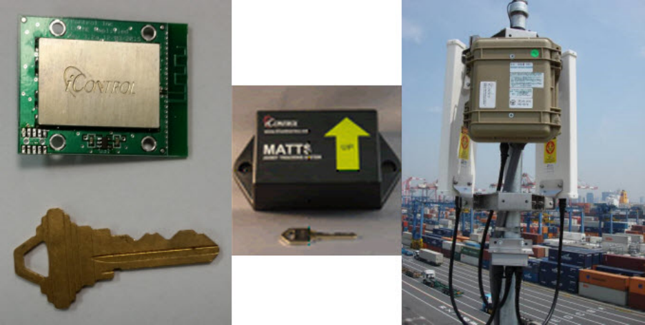
The User interface for the module is a twenty (20) pin connector on the bottom of the module.
Figure 1 iCHIME™ and Network Related Devices (Left to right: iCHIME™ Module, iTAG™ repeater for iCHIME™s,
iCHIME™ and iTAG™ reader)
iControl Incorporated
http://www.iControl-Inc.com
iCHIME™ Module Radio Operation.
This section intentionally blank for long-term confidentiality purposes.
Other Features.
In addition to the wireless radio, the iCHIME™ provides other features for system integration.
1. Two RS-232 serial UARTs are available for the User to communicate to the module from
secondary systems to transmit data via the radio transceiver. The User has complete control for
setting the baud rate, data interval and packet format for data transmission.
2. The iCHIME™ hosts eight channels of 13 bit resolution Analog to Digital conversion. These inputs
can be used to monitor external sensors attached to the iCHIME™ (temperature, pressure,
vibration, etc.). The iCHIME™ user interface includes command and data handling support to
issue alarms or automate behavior based on thresholds for these input.
3. There is an onboard temperature sensor integrated with iCHIME™. The default iCHIME™ data
packet includes the temperature data.
4. iCHIME™ provide date time stamps for all data. The onboard clock for the iCHIME™ is set to UTC
by readers in the network or from an iTAG™ GPS by commands.
iControl Incorporated
http://www.iControl-Inc.com
Functional Block Diagram.
The iCHIME™ module integrates a low power microprocessor and a 2.4Ghz radio The iCHIME™ module
also includes a software User interface for radio control and data transmission. Additionally, the
iCHIME™ can retrieve User data via the two serial UARTs or provide up to 8 channels of analog to digital
data.
Please note that the iCHIME™ uses the same command list as the iTAG™ command list. For iCHIME™
command and control, please refer to the iTAG™ Command List for a complete description of commands
that control the iCHIME™ module.
The iCHIME™ module is equipped with an integrated trace antenna rated at 3.5 dBi. All mobile
applications will utilize the integral antenna provided with the iCHIME™ module.
Optionally, a micro coax connector may be utilized to connect external antenna to the iCHIME™ module.
iControl can provide iCHIME™ modules with external antenna connectors that are certified and licensed
for external antenna operations.
NOTE: Users may not modify the antenna or its connection in anyway or risk violating radio law.
Figure 2 iCHIME™ Module Block Diagram
iControl Incorporated
http://www.iControl-Inc.com
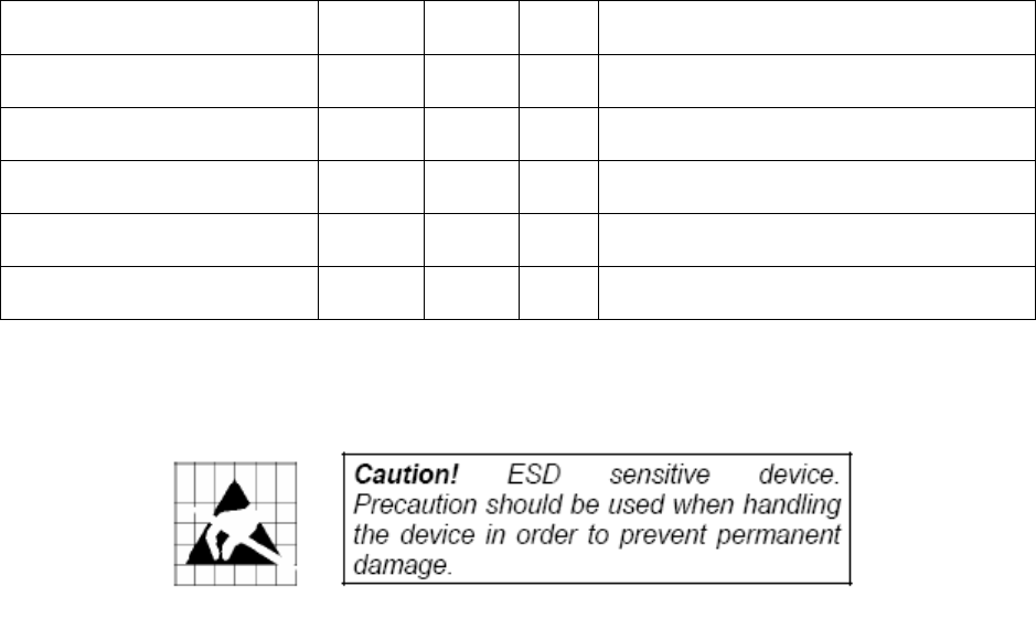
Absolute Maximum Ratings.
Under no circumstances must the absolute maximum ratings giving in this table be violated. Stress
exceeding one or more of the limiting values may cause permanent damage to the device.
Parameter
Min
Max
Units
Condition
Supply Voltage -0.3 5.5 V All supply pins must have same voltage
Voltage on any digital pin -0.3 3.6 V N/A
Input RF level 10 dBm
Storage temperature range -50 150 C
Operating ambient temperature
-40 85 C
Figure 3 Maximum Ratings
iControl Incorporated
http://www.iControl-Inc.com
OEM Installation Instruction:
An OEM integrator utilizes the 2x10 x2mm pin header connector on the bottom of the iCHIME™. To
apply power, utilize serial data, and connect to analog interfaces, the OEM must provide a 2x10 x 2mm
pin socket on their integrating electronics.
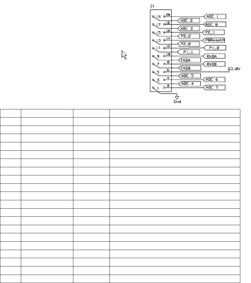
Interface Specification.
The interface diagram noted below is for the mating connector on the User’s electronics. All interfaces
to the radio are buffered to prevent User interface electronics from interfering with the operation of the
radio.
PIN Name Type Description
1 GND PWR Ground
2 Analog 7 I Analog Channel 7 (0-3.3 V input)
3 Analog 4 I Analog Channel 4 (0-3.3 V input)
4 Analog 6 I Analog Channel 6 (0-3.3 V input)
5 Analog 5 I Analog Channel 5 (0-3.3 V input)
6 VIN PWR 3.3-6.0 V input
7 TXDB Output Serial Port B transmit output (0-3.3V)
8 RXDB Input Serial Port B receive input (0-3.3V)
9 TXDA Output Serial Port A transmit output (0-3.3V)
10 RXDA Input Serial Port A receive input (0-3.3V)
11 P1_1 I/O General Purpose I/O (0-3.3 V input)
12 P1_0 I/O General Purpose I/O (0-3.3 V input)
13 P2_0 I/O General Purpose I/O (0-3.3 V input)
14 PBReset Input Reset Pin, Active low, if not used keep float
15 P2_2 I/O General Purpose I/O (0-3.3 V input)
16 P2_1 I/O General Purpose I/O (0-3.3 V input)
17 Analog 3 I Analog Channel 3 (0-3.3 V input)
18 Analog 0 I Analog Channel 0 (0-3.3 V input)
19 Analog 2 I Analog Channel 2 (0-3.3 V input)
20 Analog 1 I Analog Channel 2 (0-3.3 V input)
(Top View) Users Mating Connector for
iCHIME
™
Module
iControl Incorporated
http://www.iControl-Inc.com
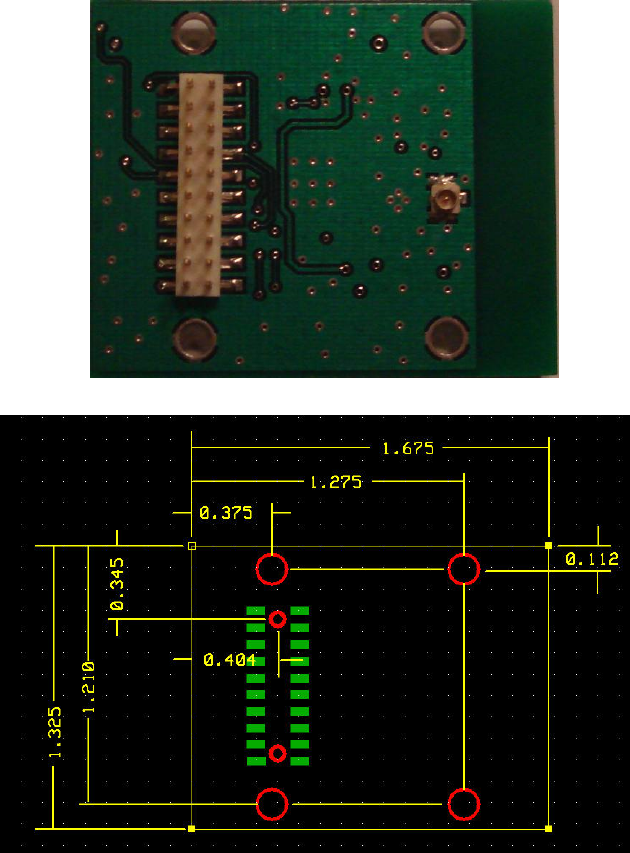
Module Mechanical Specification.
The iCHIME™ module is manufactured on a 0.062” thick FR4 PCB substrate. There are four 0.10”
mounting holes which may be used to secure the module in an enclosure or to mount on a host
motherboard. All radio components are integrated under a mechanically secure, tamperproof RF
shield.
iCHIME™ Module Mechanical Dimensions (in inches)
iControl Incorporated
http://www.iControl-Inc.com
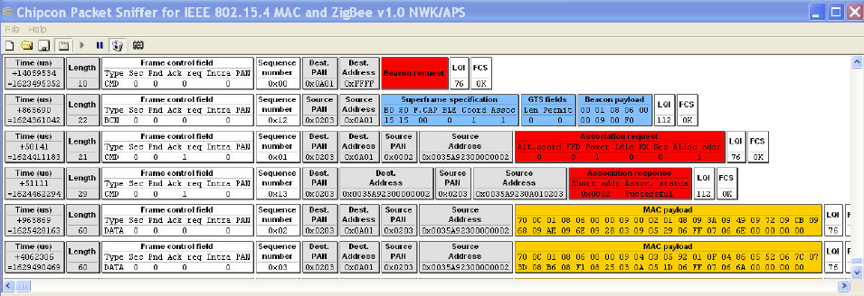
Module Unique Address Identification.
Each iCHIME™ module is assigned a unique 8 byte MAC address by iControl Incorporated. The MAC
address is used for radio network address identification. The MAC address can not be modified by the
User and is located in protected flash memory. Figure 5 depicts the communication protocol between
iControl iCHIME™ and the iGATE™ reader. The communication protocol utilizes a unique 8 byte MAC
address defined by the IEEE 802.15.4 standard.
In Figure 5,
The iCHIME™ address is (0x0035A92300000002).
The iGATE™ address is (0x0035A9230A010203).
Figure 5
iControl Incorporated
http://www.iControl-Inc.com
FCC Compliance:
This equipment has been tested and found to comply with the limits for a Class B digital device, pursuant
to Part 15 of the FCC rules. These limits are designed to provide reasonable protection against harmful
interference in a residential installation. This equipment generates, uses, and can radiate radio frequency
energy and, if not installed and used in accordance with the instructions, may cause harmful interference
to radio communications. However, there is no guarantee that interference will not occur in a particular
installation.
The iCHIME™ Module is not sold to customers or third parties as a stand-alone product at this time. Any
use of the module or system it is integrated into is controlled solely by iControl Incorporated employees.
As such, any system utilizing an iCHIME™ Module and an antenna with gain higher than 7dBi will be
configured by an iControl Incorporated employee to disable radio channel 26. Channel 26 will only be
allowed for use in systems which have antennas with 7dBi or less gain and are configured by an iControl
Incorporated employee to reduce radio transmit power to FCC acceptable levels.
Troubleshooting:
If this equipment does cause harmful interference to radio or television reception, which can be
determined by turning the equipment off and on, the user is encouraged to try to correct the interference
by one or more of the following measures:
1. Reorient or relocate the receiving antenna.
2. Increase the separation between the equipment and receiver.
3. Connect the equipment to an outlet on a circuit different from that to which the receiver is connected.
4. Consult the dealer or an experienced radio/TV technician.
Conditions:
Operation is subject to the following two conditions:
1. This device may not cause harmful interference
2. This device must accept any interference received, including interference that may cause undesired
operation.
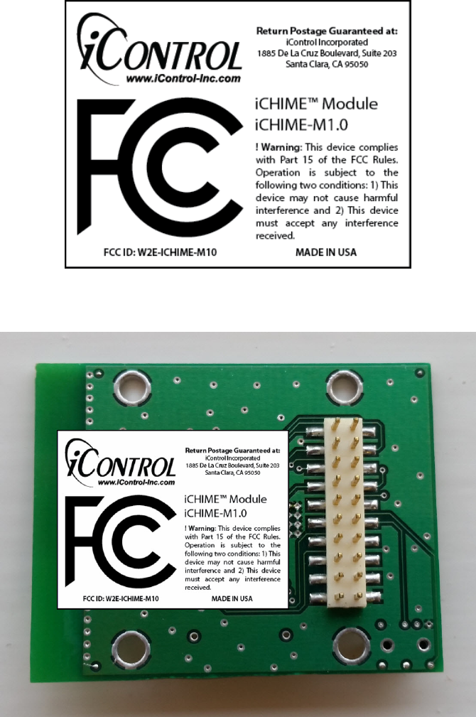
Markings:
To satisfy FCC exterior labeling requirements the following text must be placed on the exterior of the
product. FCC ID: W2E-ICHIME-M10
iControl Incorporated
http://www.iControl-Inc.com
Radio Frequency Exposure:
Notes:
1) For mobile or fixed location transmitters the minimum separation distance is 20cm, even if calculators
indicate the MPE distance is less.
2) This equipment has been evaluated in accordance with the FCC bulletin 56 “Hazards of radio
frequency and electromagnetic fields” and bulletin 65 “ Human exposure to radio frequency and
electromagnetic fields.
3) Safe operation in an uncontrolled environment will result if the following distances from the device
are maintained as a minimum.
Use of Modular Certification:
For a host manufacture’s using a certified modular, if (1) the module’s FCC ID is not visible when
installed in the host, or (2) if the host is marketed so that end users do not have straightforward
commonly used methods for access to remove the module so that the FCC ID of the module is visible;
then an additional permanent label referring to the enclosed module: “Contains Transmitter Module
FCC ID: XYZMODEL1” or “Contains FCC ID: XYZMODEL1” must be used.
iControl Incorporated
http://www.iControl-Inc.com
NCC 警語
- 減少電磁波影響,請妥適使用
(For Reducing RF Influence, Use Properly)
- 為維護隱私權,請妥適使用
(For protect individual privacy, Use Properly)
- 本器材須經專業工程人員安裝及設定,始得設置使用,且不得直接販售給一般消費者。
(This device must be installed by expert and will not be sold directly to the general public through retail
store)
- 低功率電波輻射性電機管理辦法
第十二條
經型式認證合格之低功率射頻電機,非經許可,公司、商號或使用者均不得擅自變更頻率、加大功率或變
更原設計之特性及功能。
第十四條
低功率射頻電機之使用不得影響飛航安全及干擾合法通信;經發現有干擾現象時,應立即停用,並改善至
無干擾時方得繼續使用。
前項合法通信,指依電信法規定作業之無線電通信。
低功率射頻電機須忍受合法通信或工業、科學及醫療用電波輻射性電機設備之干擾。
WARNING
Administrative Regulations on Low Power Radio Waves Radiated Devices warning:
Article 12
Without permission granted by the NCC, any company, enterprise, or user is not
allowed to change frequency, enhance transmitting power or alter original
characteristic as well as performance to an approved low power radio‐frequency
devices.
Article 14
The low power radio‐frequency devices shall not influence aircraft security and
interfere legal communications; If found, the user shall cease operating immediately
until no interference is achieved.
The said legal communications means radio communications is operated in
compliance with the Telecommunications Act.
The low power radio‐frequency devices must be susceptible with the
interference from legal communications or ISM radio wave radiated devices.