Intelyt orporated ITAGV16 Wireless GPS tracking device using 802.15.4 User Manual iTAG QuickStartManual Rev2
iControl Incorporated Wireless GPS tracking device using 802.15.4 iTAG QuickStartManual Rev2
Users Manual
iControlIncorporated
http://www.iControl‐Inc.com
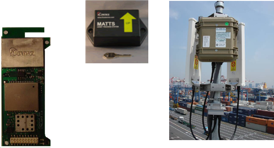
iTAGModule
IntegratediTAG
WithEnclosure
iTAGReaderutilizingan
InternaliTAGModule
iTAGModule
OperatingManual
Background.
TheiTAGis2.4GHzbi‐directionalradiotransceiverthatisintegratedwithaGPSreceiver,motion
detectingsensor,andnon‐volatileflashmemoryfordatastorage.AUsermayconfigurethedeviceto
operateasaRadioFrequencyIdentificationDevice(RFID)fortrackingshippingcontainersina
worldwidesupplychainusingtheMarineAssetTagTrackingSystem(MATTS)communicationprotocol.
AniTAGmoduleutilizesalowpower,wireless,radiooperatinginthe2.4GHzbandasitsprimarymode
ofcommunication.ThewirelessradiooperatesincompliancewithIEEEStandard802.15.4‐2006.The
iTAGGPSreceiverisUserconfigurabletoperiodicallydeterminetheiTAG’sgloballocationusingdata
fromtheUSAFGPSconstellation.Themodulemayoperateasstandalonedeviceormaybeusedasa
radioandGPSreceiverforcommunicationdevicesthatareapartoflargesystemsorsecuritydevices.
TheUserinterfaceforthemoduleisviaatwenty(20)pinconnectoronthebottomofthemodule.
Figure1iTAGDevices
iControlIncorporated
http://www.iControl‐Inc.com
iTAGRadioOperation.
TheiTAGiscontrolledviaaserialportinterfaceforinitialconfigurationandcheckout.Allcommandsfor
controllingtheradioareidentifiedintheiTAGCommandList.OnceaUserascompletedtheinitialiTAG
configuration,completecontrolandoperationoftheiTAGcanbeaccomplishedthroughtheradiolink
interfaceusingthesamecommandsavailableintheiTAGCommandList.
TheradiointheiTAGisnominallyoperatedinapowersavingmodewiththereceiverperiodically
enabledand“listening”forcommandsordatarequests.Akeyelementtothepowersavingmodeis
theprincipleof“tag‐talks‐last”.Inthismode,batterypowerisconservedbyonlyrespondingto
messagesthataresentdirectlytothespecificiTAGMACaddressormutualbroadcastaddress.Fora
majorityofiTAGoperation,theiTAGisinadeeppowersavingmode(~98%ofthetime).TheiTAGwill
onlytransmitwhenitreceivesaproperlyencryptedmessageduringitsreceiveractiveperiod.The
encryptedmessagedirectedtotheiTAGmayincludeinformationaboutwhichchanneltheiTAGshould
useforfurthertransmissions.Once,thecommunicationparametersareexchanged,therewilltypically
beaperiodaseveralsecondsofactiveradiotransmissionastheiTAGrelaysdata.Thedatatransmitted
mayeitherbesecuritydatadestinedforgovernmentservers,and/orcommercialdatadestinedforthe
endcustomer.Thisdatamayoriginatefrominternalflashstorageoritmaybereceivedandrelayed
fromanothercompatibledevice.
OtherComponents.
Inadditiontothewirelessradio,severalotherelectronicdevicesareusedbytheiTAG.
1. Thelow‐powerGPSreceiverispoweredperiodicallytoreceiveGPSsignals.TheGPSreceiveris
typicallypoweredforlessthanoneminuteperhour;howeverthefrequencyofGPSfixesis
highlyconfigurabletoaccommodateavarietyofrequirementsandmayvarybasedonother
inputs.
2. Alow‐powerMEMSaccelerometerisusedtodetectmotion.Usingapatentpendingprocess,
theiTAGutilizethemotiondetectionsensortoestablishifanewGPSfixisrequired.
3. Analogsignalsmaybemonitoredtodetectsecurityrelatedinformation(e.g.temperature,
enclosurebreach,installationsecurityetc.)
4. TwoRS‐232serialUARTsareavailablefortheUsertocommunicatedatatothemodulefrom
secondarysystemstotransmitdataviatheradiotransceiver.
iControlIncorporated
http://www.iControl‐Inc.com
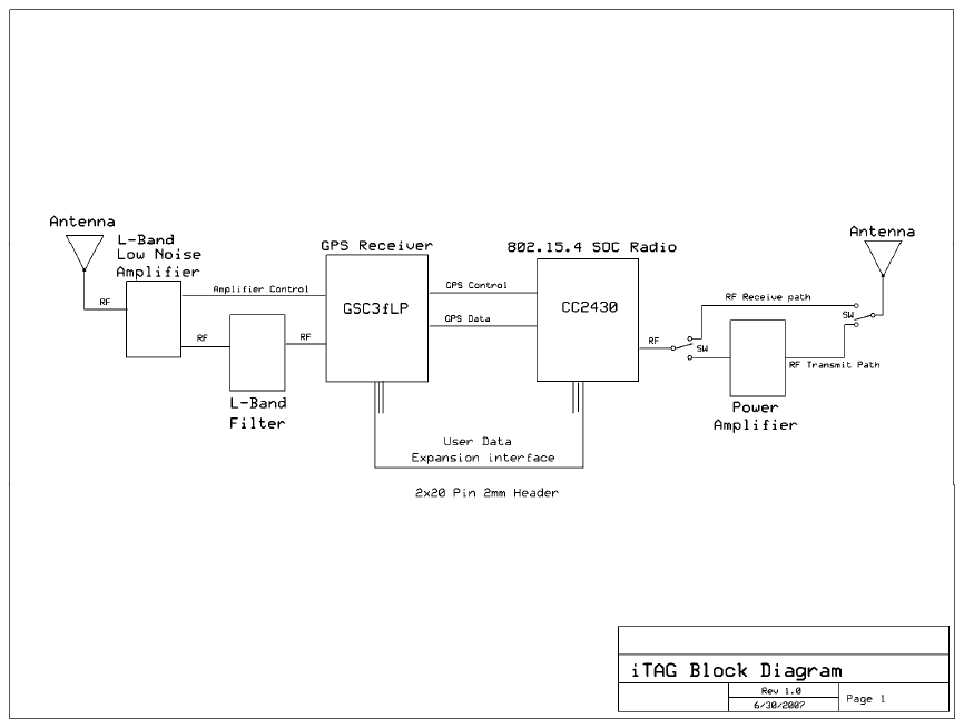
FunctionalBlockDiagram.
TheiTAGmoduleintegratesaGPSreceiver,a2.4Ghzradio,andalowpowermicroprocessor.The
iTAGmodulealsoincludesasoftwareUserinterfacethatprovidescommandsforcontrollingtheradio
functions,sendingdata,retrievingGPSlocation,anduploadingstoreddata.
Note:PleaserefertotheiTAGCommandListforacompletelistofoperatingcommandsthatcontrolthe
iTAGmodule.
TheiTAGmoduleisequippedwithanintegratedtraceantennaratedat3.0dBi.Mostembeddedmobile
applicationswillutilizetheintegralantennaprovidedwiththeiTAGmodule.
Optionally,amicrocoaxconnectormaybeutilizedtoconnectexternalantennatotheiTAGmodule.
iControlcanprovideiTAGmoduleswithexternalantennaconnectorsthatarecertifiedandlicensedfor
externalantennaoperations.
NOTE:Usersmaynotmodifytheantennaorit’sconnectioninanywayorriskviolatingradiolaw.
Figure2iTAGBlockDiagram
iControlIncorporated
http://www.iControl‐Inc.com
AbsoluteMaximumRatings.
Undernocircumstancesmusttheabsolutemaximumratingsgivinginthistablebeviolated.Stress
exceedingoneormoreofthelimitingvaluesmaycausepermanentdamagetothedevice.
Parameter Min Max Units Condition
Supply Voltage -0.3 6.0 V All supply pins must have same voltage
Voltage on any digital pin -0.3 3.6 V
Input RF level 10 dBm
Storage temperature range -50 150 C
Operating ambient temperature -40 85 C
Figure3MaximumRatings
iControlIncorporated
http://www.iControl‐Inc.com
GeneralCharacteristics.
iControlIncorporated
http://www.iControl‐Inc.com
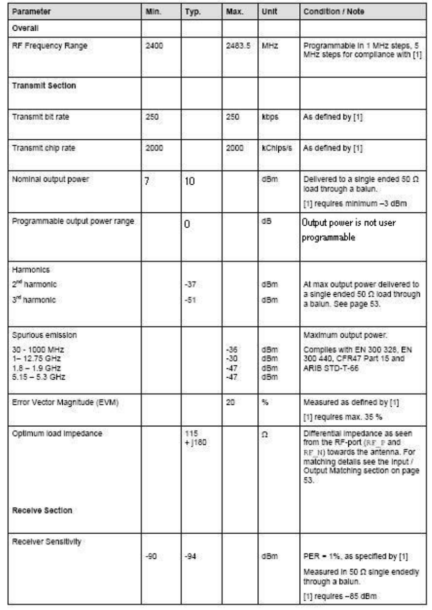
iTAGRadioSpecification(Transmit).

iControlIncorporated
http://www.iControl‐Inc.com
iTAGRadioSpecification(Receive).

iControlIncorporated
http://www.iControl‐Inc.com
OEMInstallationInstruction:
AnOEMintegratorutilizesthe2x10x2mmpinheaderconnectoronthebottomoftheiCHIME.
Toapplypower,utilizeserialdata,andconnecttoanaloginterfaces,theOEMmustprovidea2x10x
2mmpinsocketontheirintegratingelectronics.
InterfaceSpecification.
TheinterfacediagramnotedbelowisforthematingconnectorontheUser’selectronics.All
interfacestotheradioarebufferedtopreventUserinterfaceelectronicsfrominterferingwiththe
operationoftheradio.
PIN Name Type Description
1 GND PWR Ground
2 Analog 7 I Analog Channel 7 (0-3.3 V input)
3 Analog 4 I Analog Channel 4 (0-3.3 V input)
4 Analog 6 I Analog Channel 6 (0-3.3 V input)
5 Analog 5 I Analog Channel 5 (0-3.3 V input)
6 VIN PWR 3.3-6.0 V input
7 TXDB Output Serial Port B transmit output (0-3.3V)
8 RXDB Input Serial Port B receive input (0-3.3V)
9 TXDA Output Serial Port A transmit output (0-3.3V)
10 RXDA Input Serial Port A receive input (0-3.3V)
11 P1_1 I/O General Purpose I/O (0-3.3 V input)
12 P1_0 I/O General Purpose I/O (0-3.3 V input)
13 P2_0 I/O General Purpose I/O (0-3.3 V input)
14 PBReset Input Reset Pin, Active low, if not used keep float
15 P2_2 I/O General Purpose I/O (0-3.3 V input)
16 P2_1 I/O General Purpose I/O (0-3.3 V input)
17 Analog 3 I Analog Channel 3 (0-3.3 V input)
18 Analog 0 I Analog Channel 0 (0-3.3 V input)
19 Analog 2 I Analog Channel 2 (0-3.3 V input)
20 Analog 1 I Analog Channel 2 (0-3.3 V input)
(TopView)UsersMatingConnectorfor
iTAGModule

iControlIncorporated
http://www.iControl‐Inc.com
ModuleMechanicalSpecification.
TheiTAGmoduleismanufacturedona0.062”thickFR4PCBsubstrate.Therearefour0.10”
diametermountingholeswhichmaybeusedtosecurethemoduleinanenclosureortoahost
motherboard.Allradiocomponentsareintegratedunderamechanicallysecure,tamperproofRF
shield.TheGPSantennafortheiTAGmoduleisaceramicpatchantennathatislocatedonthetop
ofthemodule.FornormalGPSoperations,themoduleshouldbeorientedsothattheGPSpatch
antennaispointedskyward.
iTAGModuleMechanicalDimensions(ininches)

iControlIncorporated
http://www.iControl‐Inc.com
ModuleUniqueAddressIdentification.
EachiTAGmoduleisassignedaunique8byteMACaddressbyiControlIncorporated.TheMACaddress
isusedforradionetworkaddressidentification.TheMACaddresscannotbemodifiedbytheUserand
islocatedinprotectedflashmemory.Figure5depictsthecommunicationprotocolbetweeniControl
iTAGandtheiGATEreader.Thecommunicationprotocolutilizesaunique8byteMACaddressdefined
bytheIEEE802.15.4standard.
InFigure5,
TheiTAGaddressis(0x0035A923000000002).
TheiGATEaddressis(0x0035A9230A010203)
Figure10
iControlIncorporated
http://www.iControl‐Inc.com
FCCCompliance:
This equipment has been tested and found to comply with the limits for a Class B digital device, pursuant
to Part 15 of the FCC rules. These limits are designed to provide reasonable protection against harmful
interference in a residential installation. This equipment generates, uses, and can radiate radio frequency
energy and, if not installed and used in accordance with the instructions, may cause harmful interference
to radio communications. However, there is no guarantee that interference will not occur in a particular
installation.
Troubleshooting:
If this equipment does cause harmful interference to radio or television reception, which can be
determined by turning the equipment off and on, the user is encouraged to try to correct the interference
by one or more of the following measures:
1. Reorient or relocate the receiving antenna.
2. Increase the separation between the equipment and receiver.
3. Connect the equipment to an outlet on a circuit different from that to which the receiver is connected.
4. Consult the dealer or an experienced radio/TV technician.
Conditions:
Operation is subject to the following two conditions:
1. This device may not cause harmful interference
2. This device must accept any interference received, including interference that
may cause undesired operation.
Markings:
TosatisfyFCCexteriorlabelingrequirementsthefollowingtextmustbeplacedontheexteriorofthe
product.
ContainsModuleFCCID:FCCID:W2E‐ITAGV16
iControlIncorporated
http://www.iControl‐Inc.com
FCCWarnings:
Modifications: Modifications not expressly approved by the manufacturer could void the user’s
authority to operate the equipment under FCC Rules.
RadioFrequencyExposure:
Notes:
1)Formobileorfixedlocationtransmitterstheminimumseparationdistanceis20cm,evenifcalculators
indicatetheMPEdistanceisless.
2)ThisequipmenthasbeenevaluatedinaccordancewiththeFCCbulletin56“Hazardsofradio
frequencyandelectromagneticfields”andbulletin65“Humanexposuretoradiofrequencyand
electromagneticfields.
3)Safeoperationinanuncontrolledenvironmentwillresultifthefollowingdistancesfromthedevice
aremaintainedasaminimum.