Intelyt orporated ITAGV33 GPS tracking device with 802.15.4 Radio and 3G cell modem User Manual iDAC Mode
iControl Incorporated GPS tracking device with 802.15.4 Radio and 3G cell modem iDAC Mode
UserManual.wiki
>
Intelyt orporated
>
ITAGV33 User Manual
Command List
Navigation menu
Upload a User Manual
Namespaces
Wiki Guide
HTML
PDF
Info
Views
User Manual
Discussion / Help
Navigation

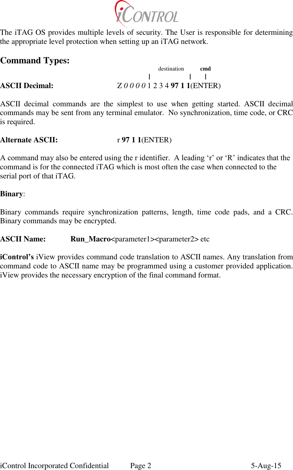
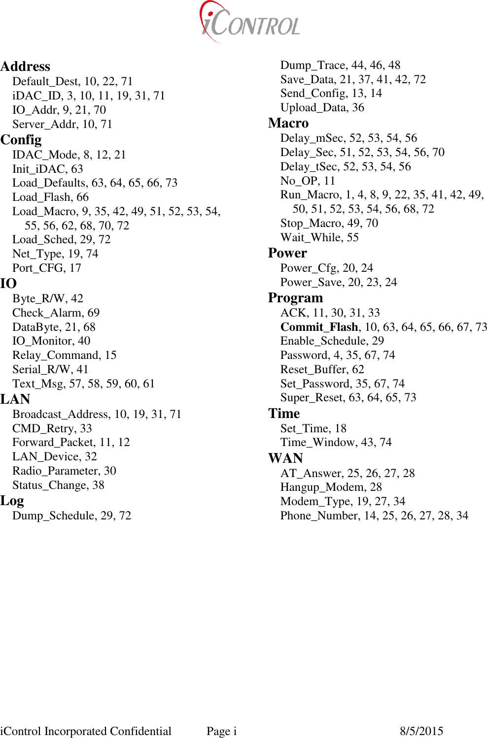
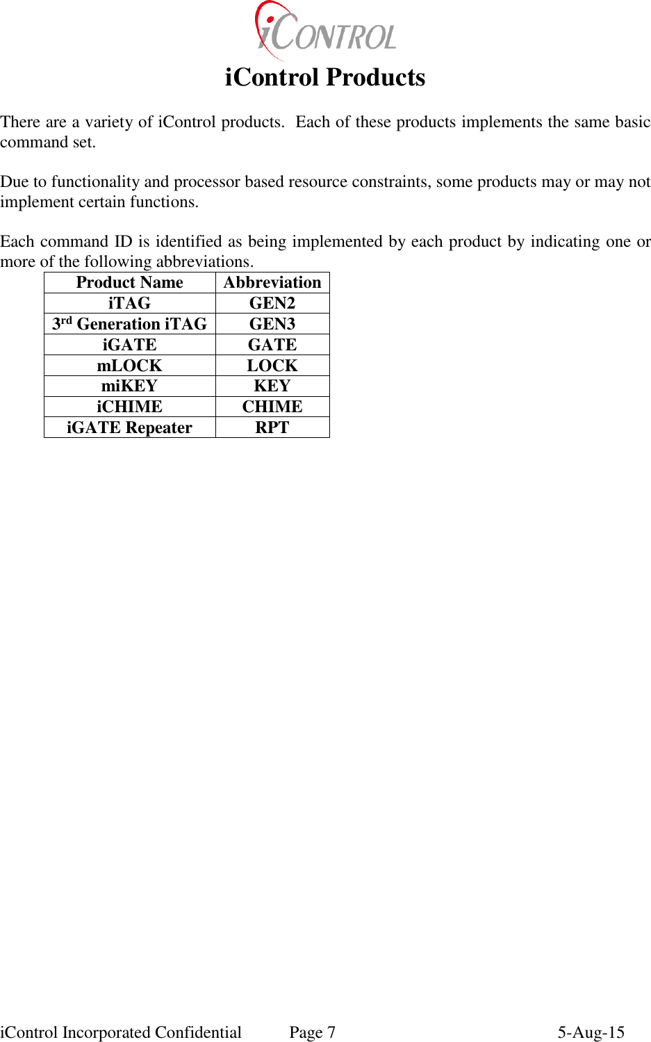
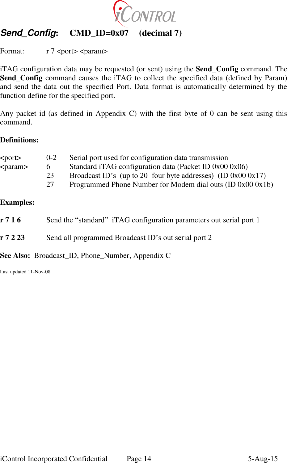
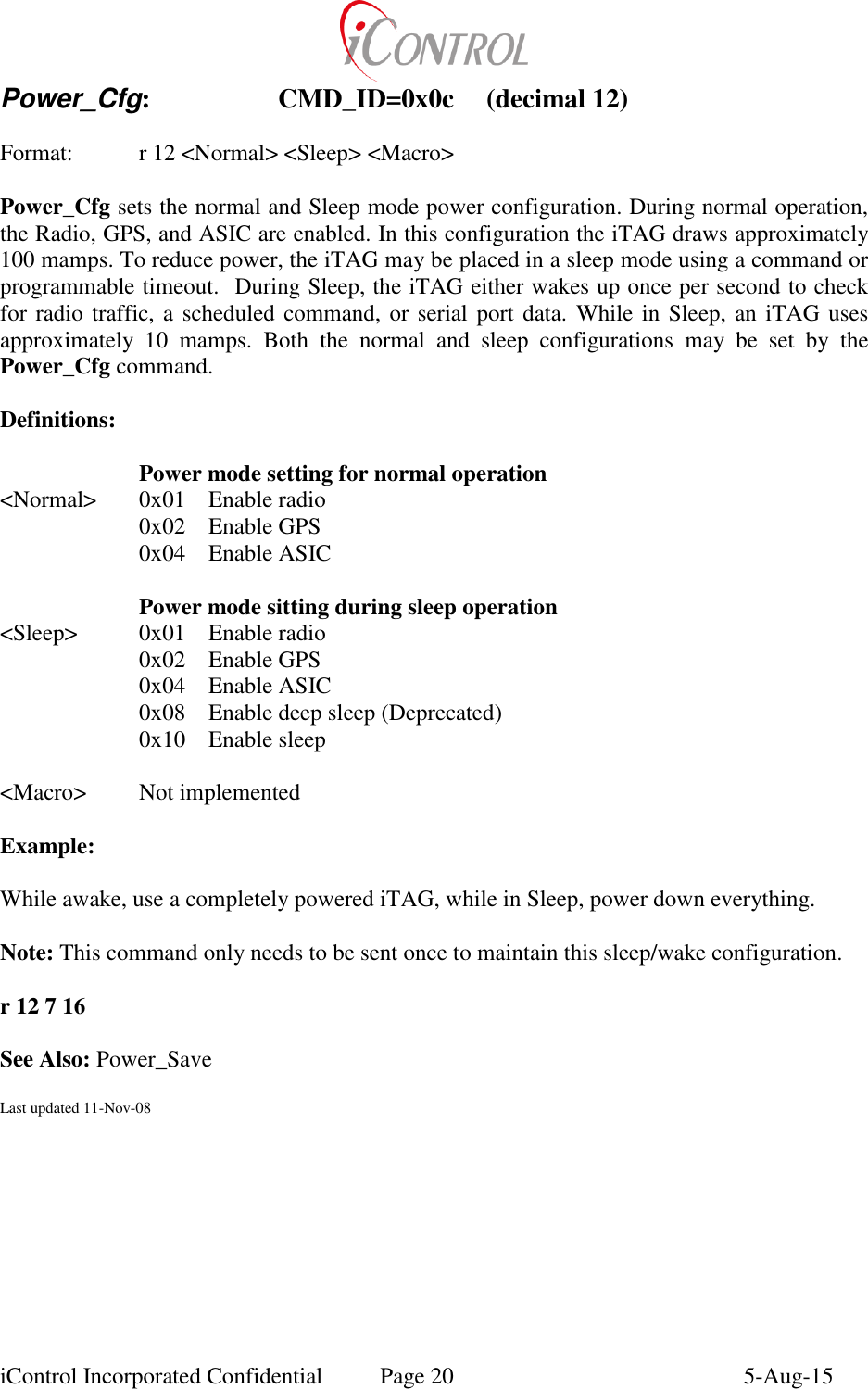
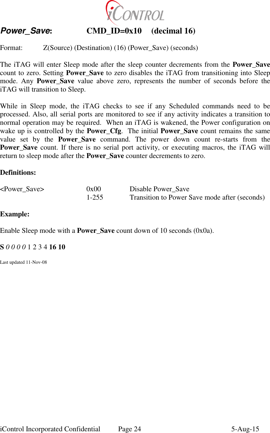
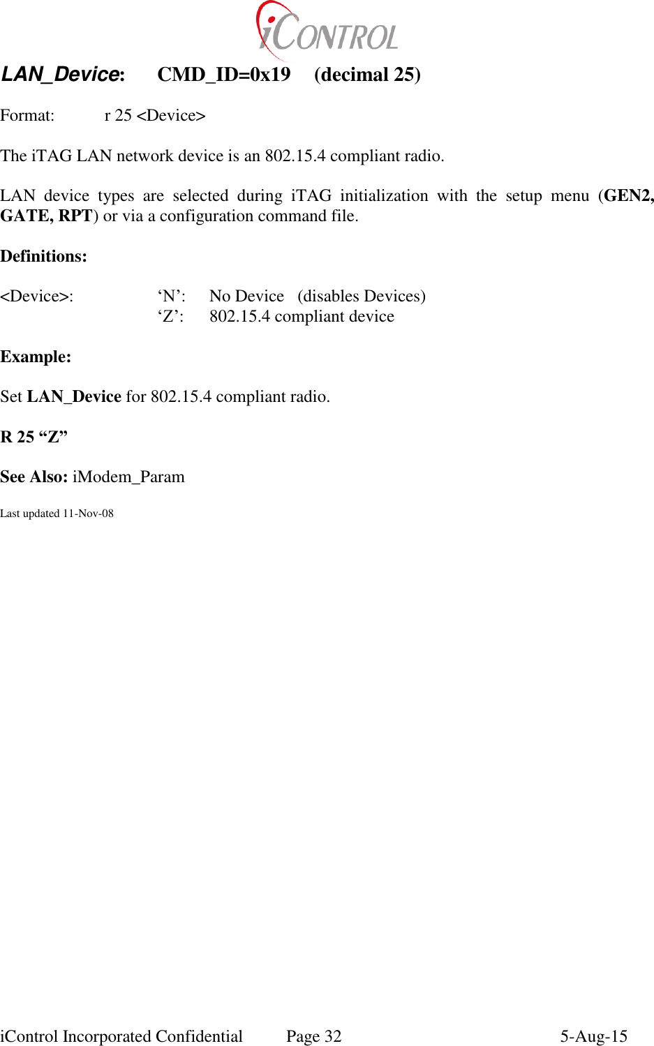
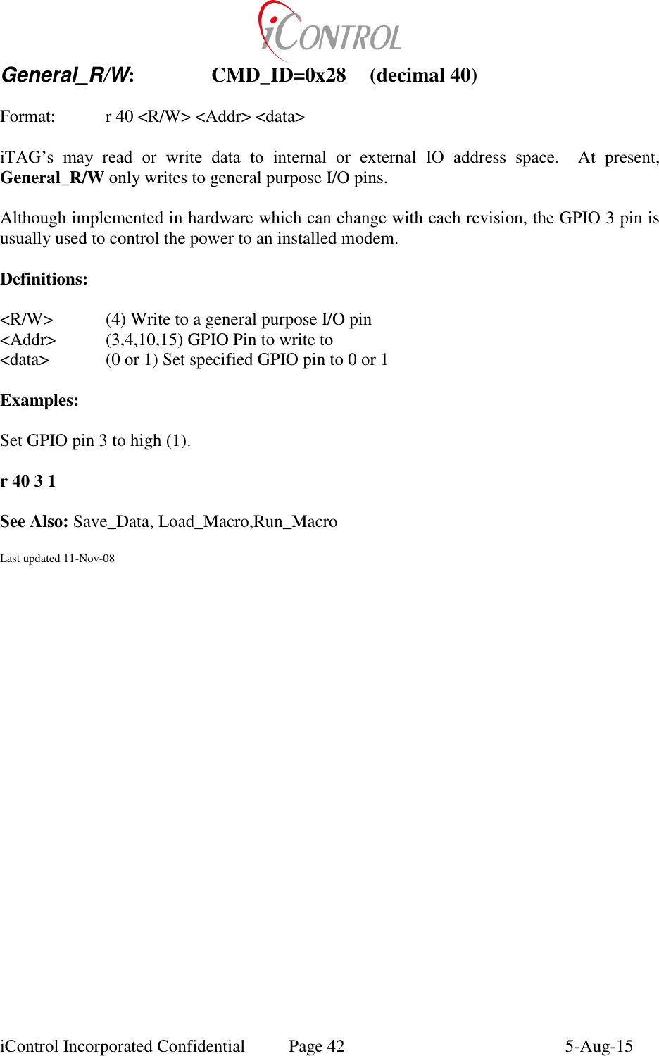
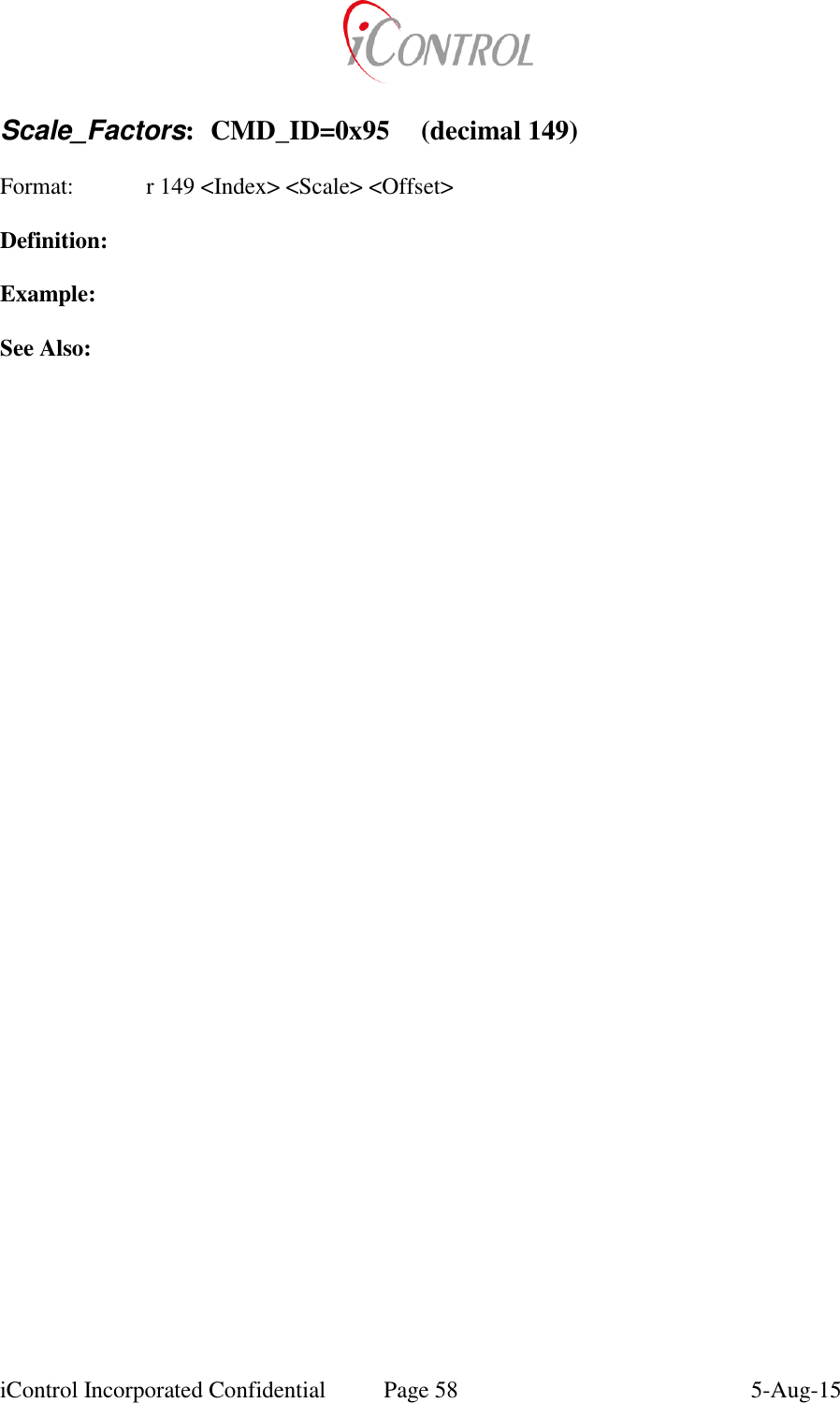
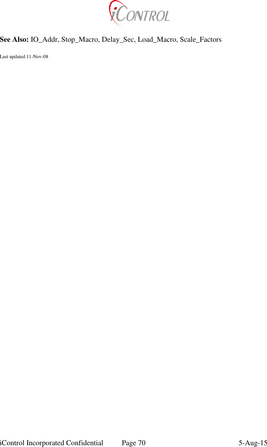
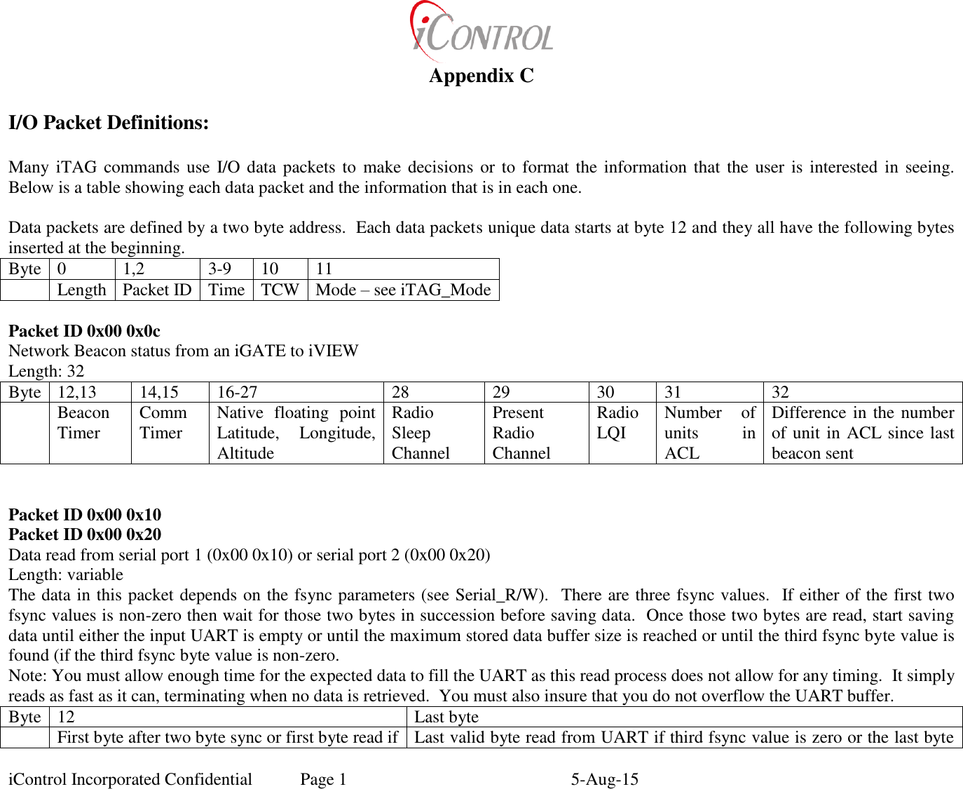
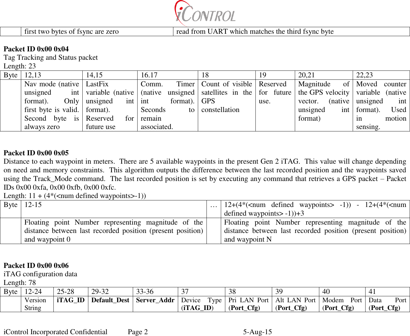
![iControl Incorporated Confidential Page 4 5-Aug-15 ASCII Command Files: iTAG ASCII commands may be grouped in a file and loaded all at once with a terminal emulator or other PC application. The command files may be built using common text editors such as Notepad, Word, etc. iTAG command files may include comment fields and up to 1k bytes of commands to be sent. All characters following a “//” are considered comments and are ignored by the iTAG processing functions. The only iTAG serial ports which are enabled for ASCII commanding are User Port, Modem Port, or DataPort. If password protection is enabled for ASCII commanding, include a Password command at the beginning of the command file. ASCII Command File Examples: The following text may be copied and pasted into a text (.txt) file. If HyperTerminal (or other application) sends this file to an iTAG (via modem, User Port etc) the iTAG will process all commands and commit them to flash. Example1.txt // This File is an iTAG command file. // To load, send file using any terminal emulator with a “Transfer Text” Option // Send file once. The iTAG will begin running its schedule as long as schedule // checking is enabled. // R 253 0 255 255 255 255 23 30 0 97 6 1 // Run Macro 6 at 11:30:00 PM R 253 1 255 255 255 255 4 15 0 97 0 1 // Run Macro 0 at 4:15:00 AM R 253 2 255 255 255 255 19 15 97 0 1 // Run Macro 0 at 7:15:00 PM R 99 0 16 2 18 0 2 17 1 4 100 0 2 120 2 17 0 1 20 // Load Macro 0 R 99 6 5 2 18 1 1 29 // Load Macro 6 R 240 // Commit to flash Example2.txt // This File is an iTAG command file. // To load , send file using any terminal emulator with a “Transfer Text” Option // Send file once. // File loads Macro with Relay cycling Macro. Turns all relays off, delays 0.100 seconds, // Turns all relays on // R 99 0 15 4 8 2 0 0 4 101 0 0 1 4 8 2 255 255// Load Macro 0 w/Relay cmds R 240 // Commit to flash To run Example2, send the command; R 97 0 1 (Run_Macro[0] once)](https://usermanual.wiki/Intelyt-orporated/ITAGV33/User-Guide-2730363-Page-7.png)
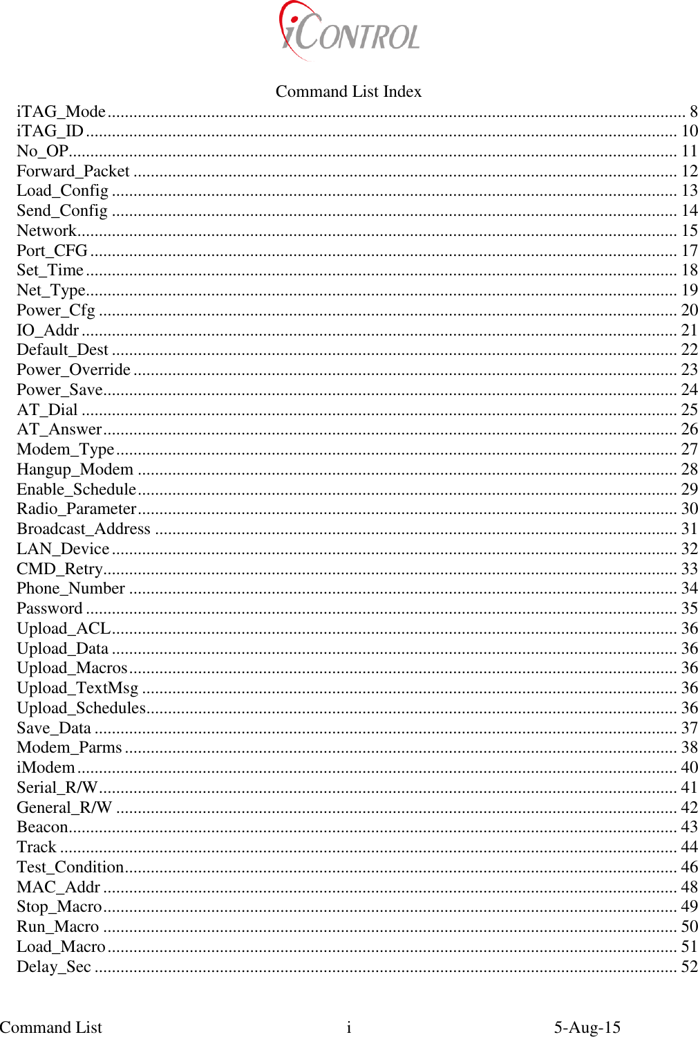
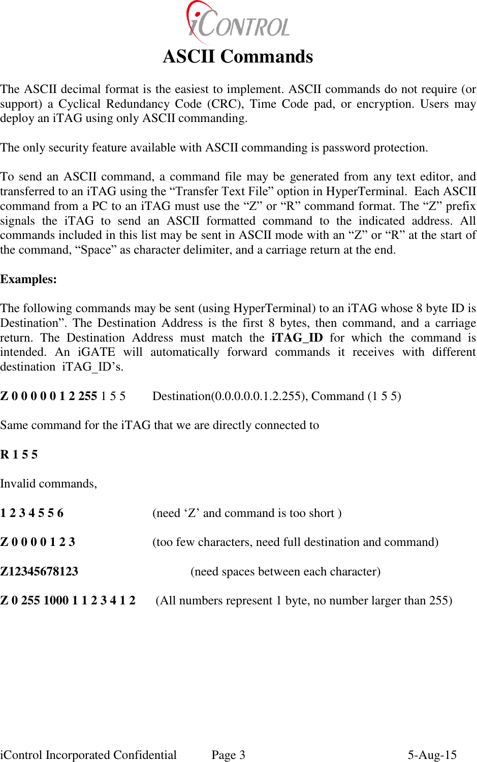
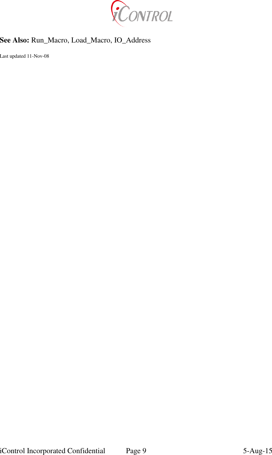
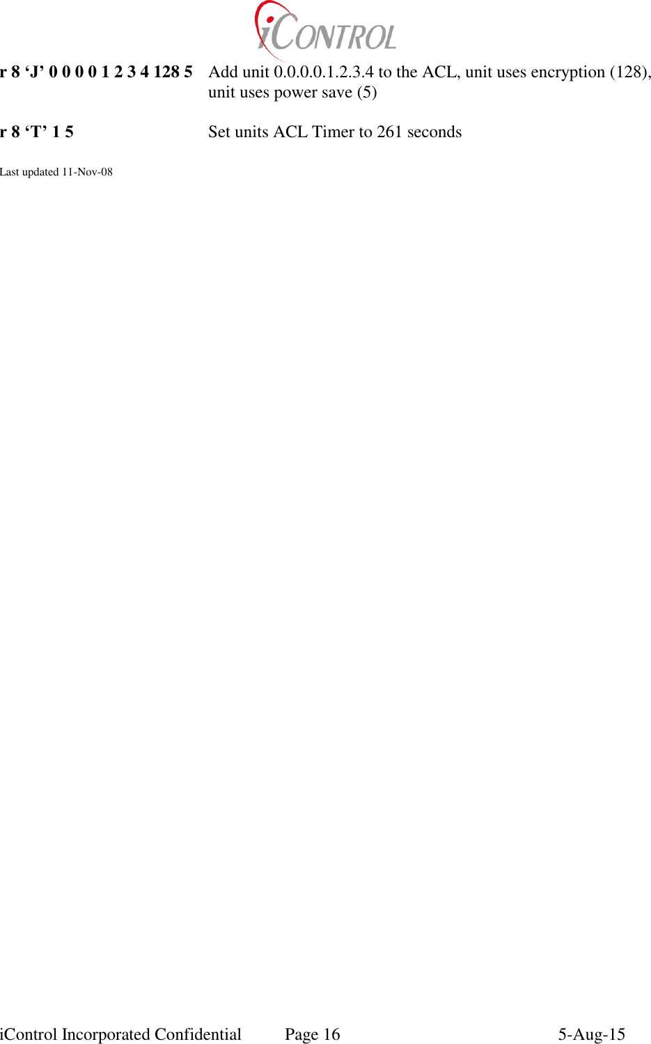
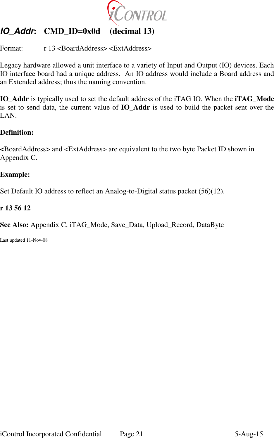
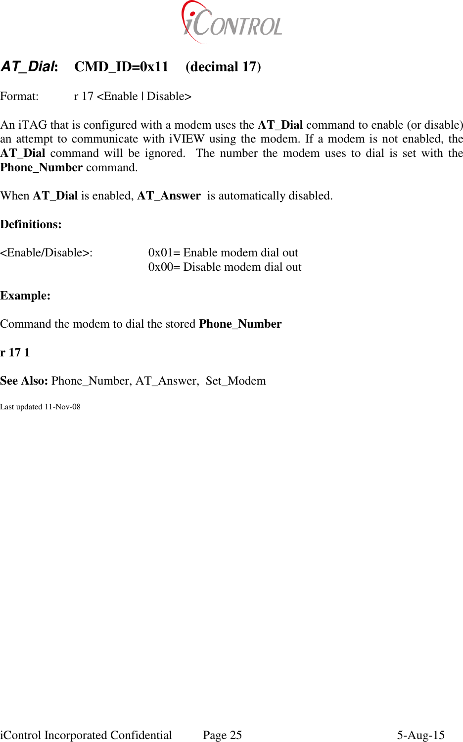
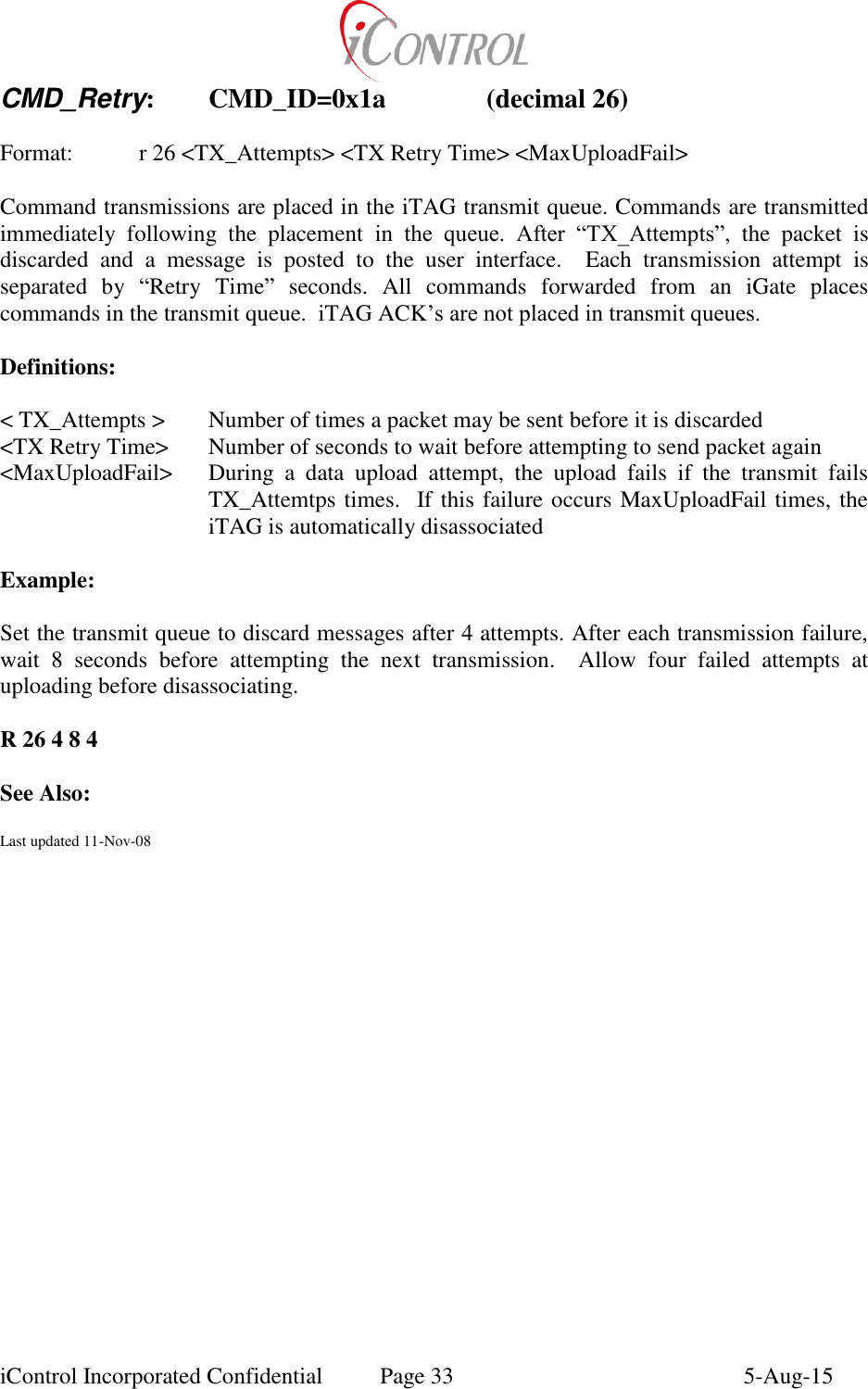
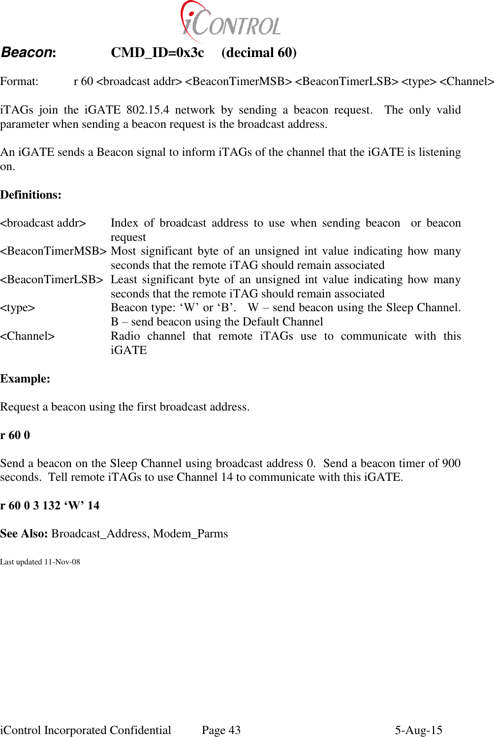
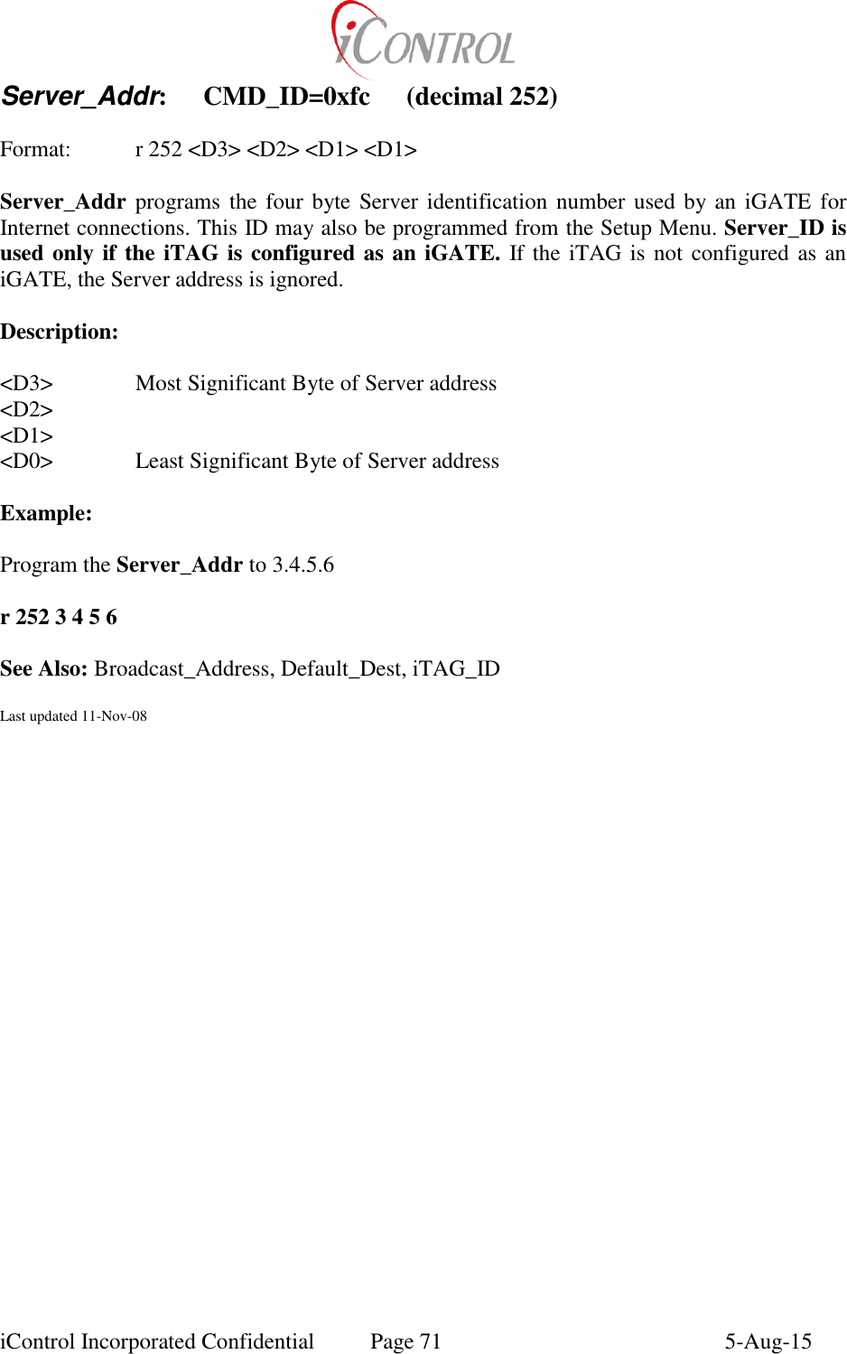
![iControl Incorporated Confidential Page 8 5-Aug-15 Command List iTAG_Mode: CMD_ID=0x01 (decimal 1) Format: r 1 <iTAG_Mode> [Param] iTAG_Mode sets the data reporting function on the iTAG. Additional functionality may also be accomplished by appending Run_Macro commands to the end of the iTAG_Mode command. If a User wishes to execute additional commands while the iTAG is in a broadcast mode, other iTAG functions may be linked to the mode by pointing to a Macro at the end of the iTAG mode command. While the iTAG mode is 0x00 (0) the iTAG is not broadcasting data over the Local Area Network (LAN). Definitions: <Param> <iTAG_Mode> 0x00 Silent N/A 0x01 One Sample N/A 0x02 Stream (1Hz): N/A 0x05 Stream “N” Samples (0<”N”<255) (Once per second) 0x06 Stream Samples (0<”N”<255) (For “N” minutes) 0x0a Send record to default destination P1: IO MSB Address P2: IO LSB Address P3: Xmit Port 0x0b Send record to destination P1: IO MSB Address P2: IO LSB Address P3: Xmit Port P4-P7: Destination Address 0x0c Send record using repeater channel (RPT) P1: IO MSB Address P2: IO LSB Address P3: don’t care P5: 0, use repeater channel Otherwise, indicates channel Example: Append the Run_Macro command at the end of the iTAG_Mode to cause the iTAG to execute Macro_ID (3) once per second while transmitting data over the LAN. r 1 2 97 3 1](https://usermanual.wiki/Intelyt-orporated/ITAGV33/User-Guide-2730363-Page-11.png)
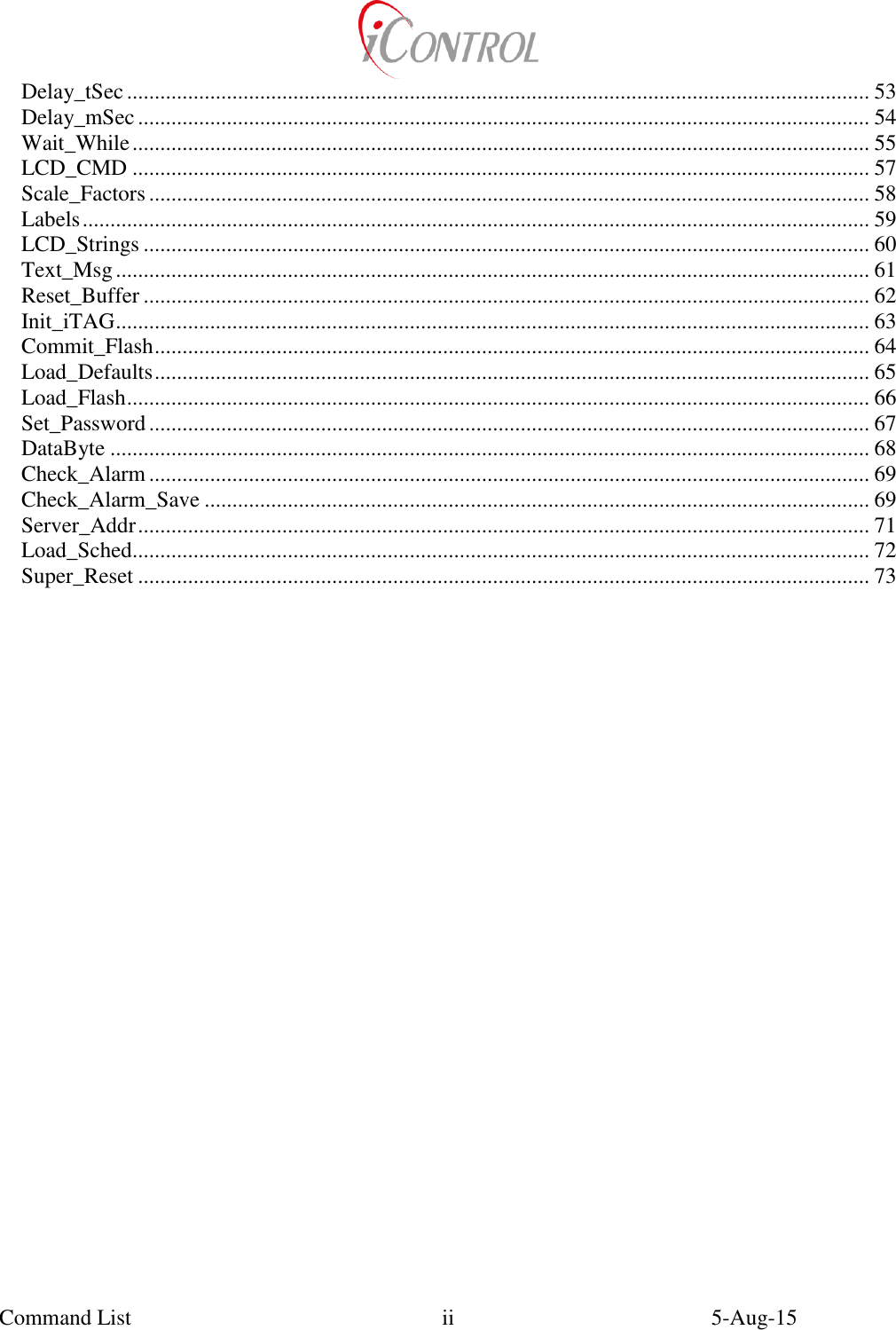
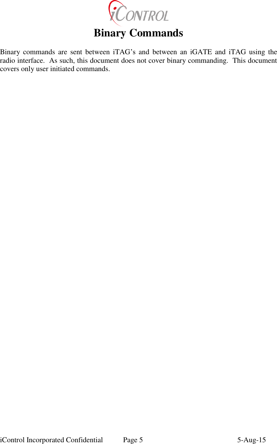
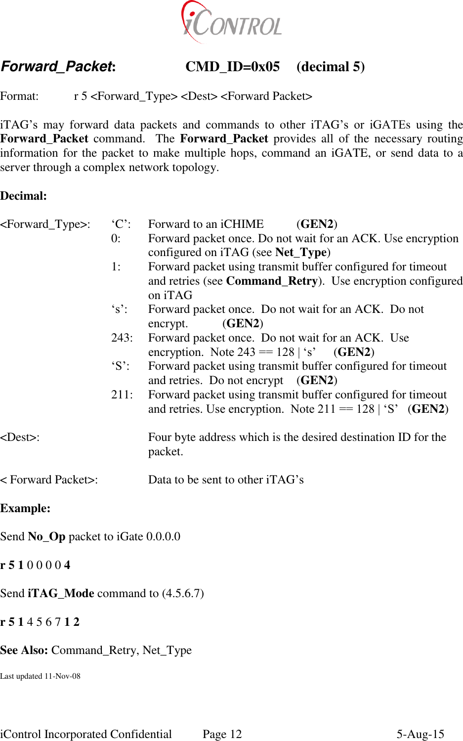
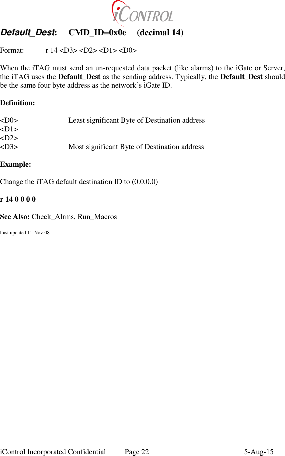
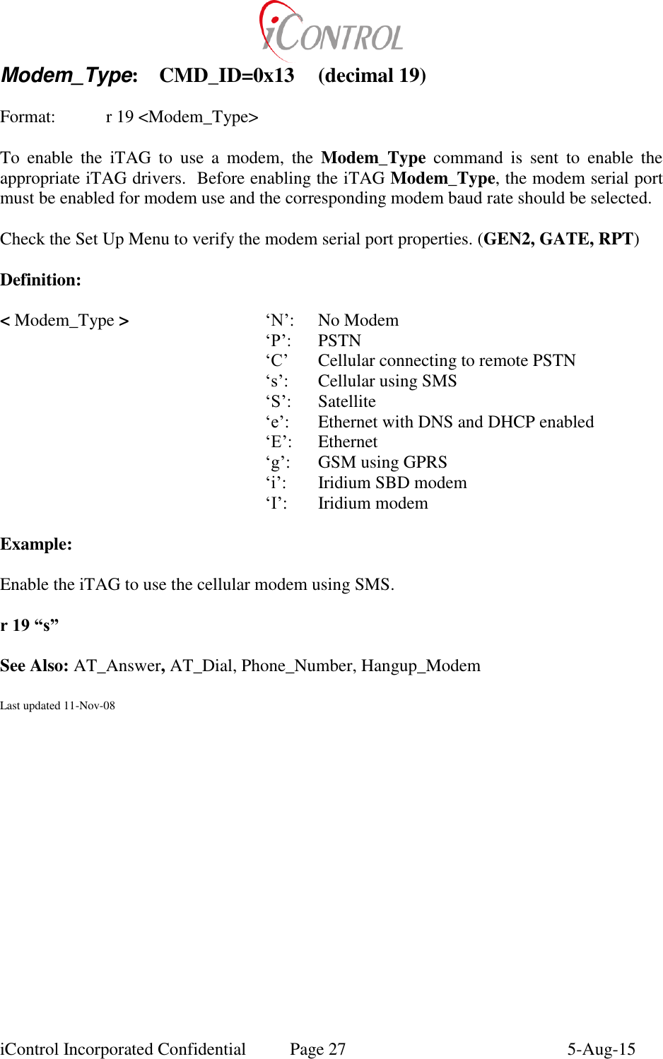
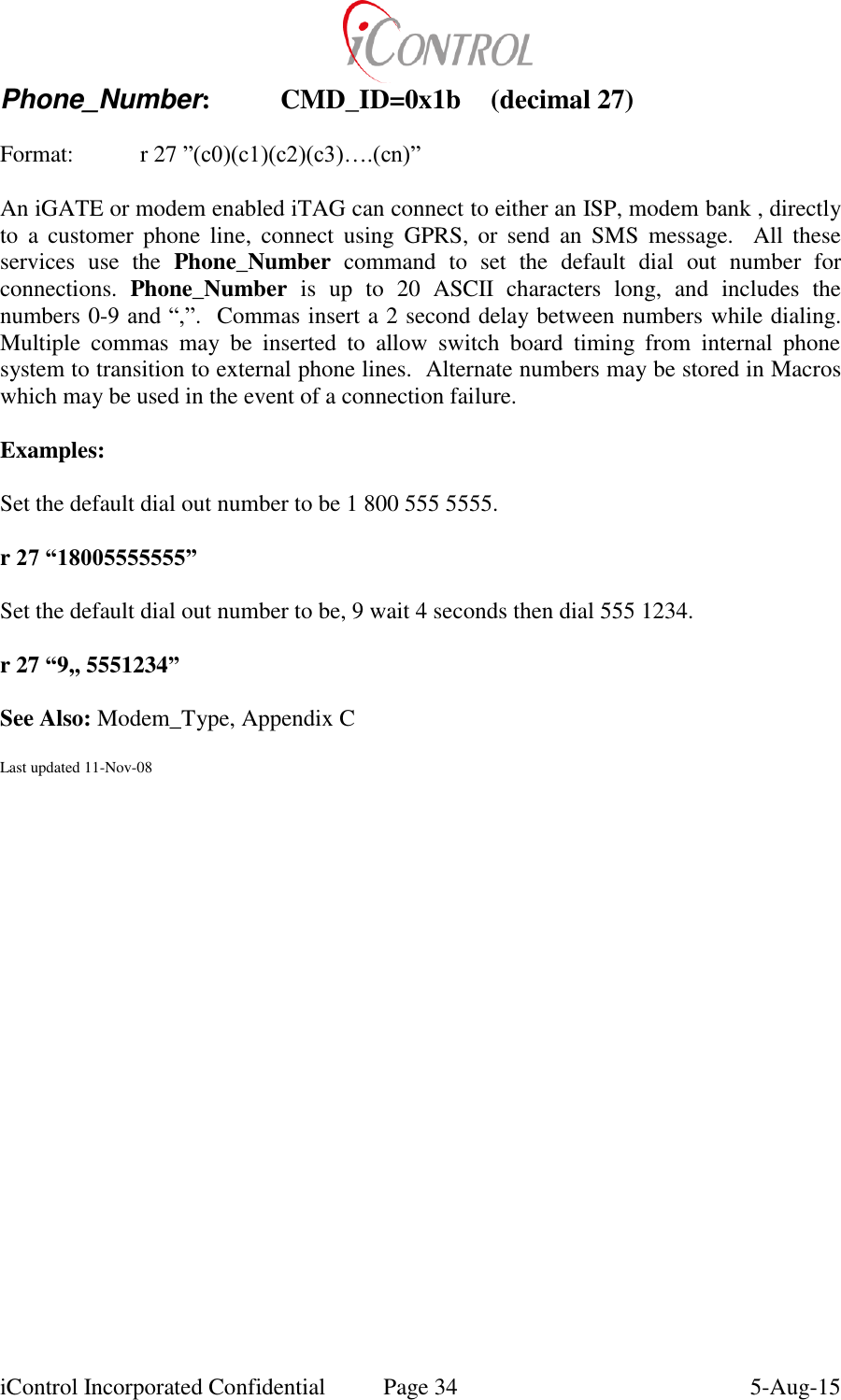
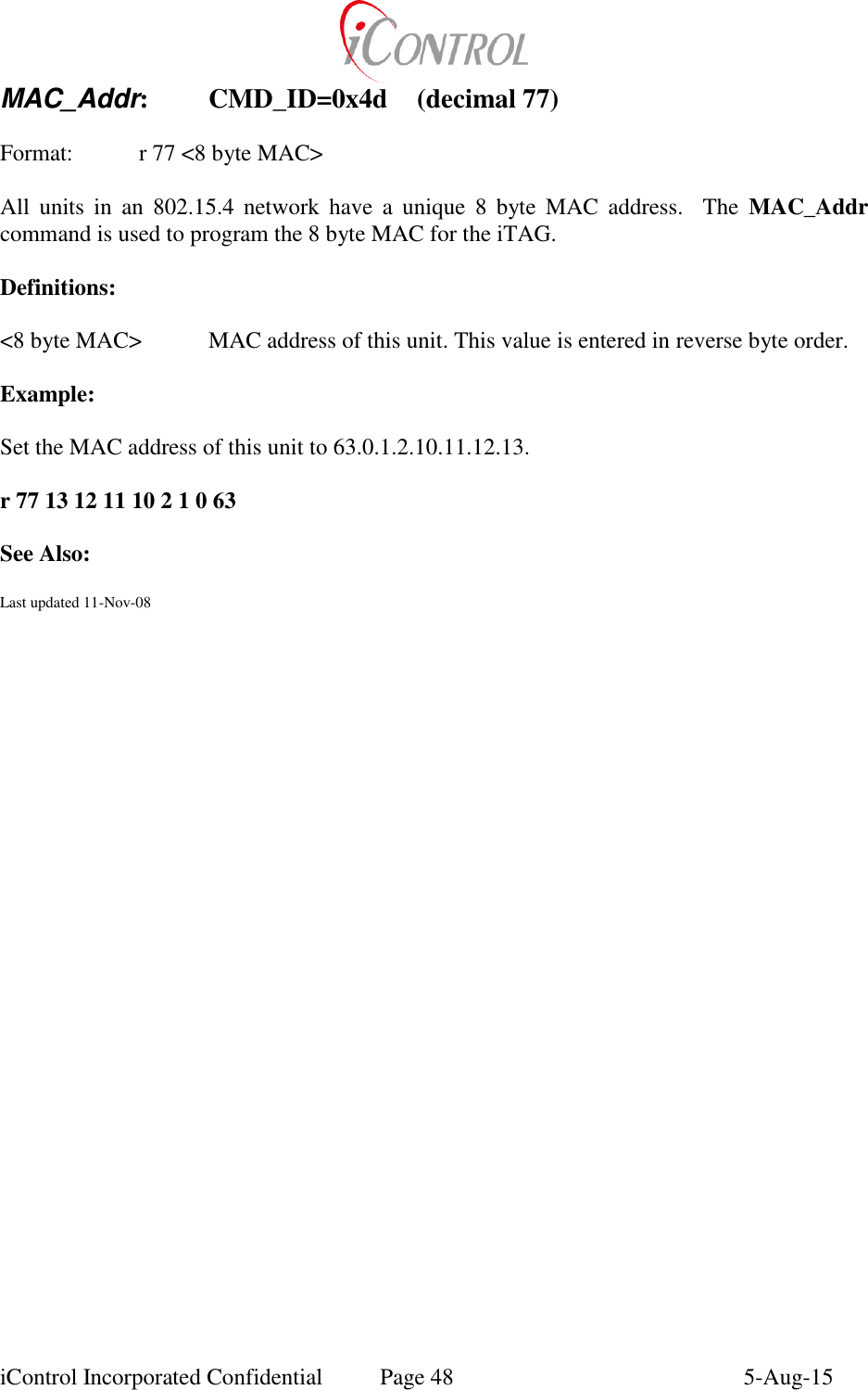
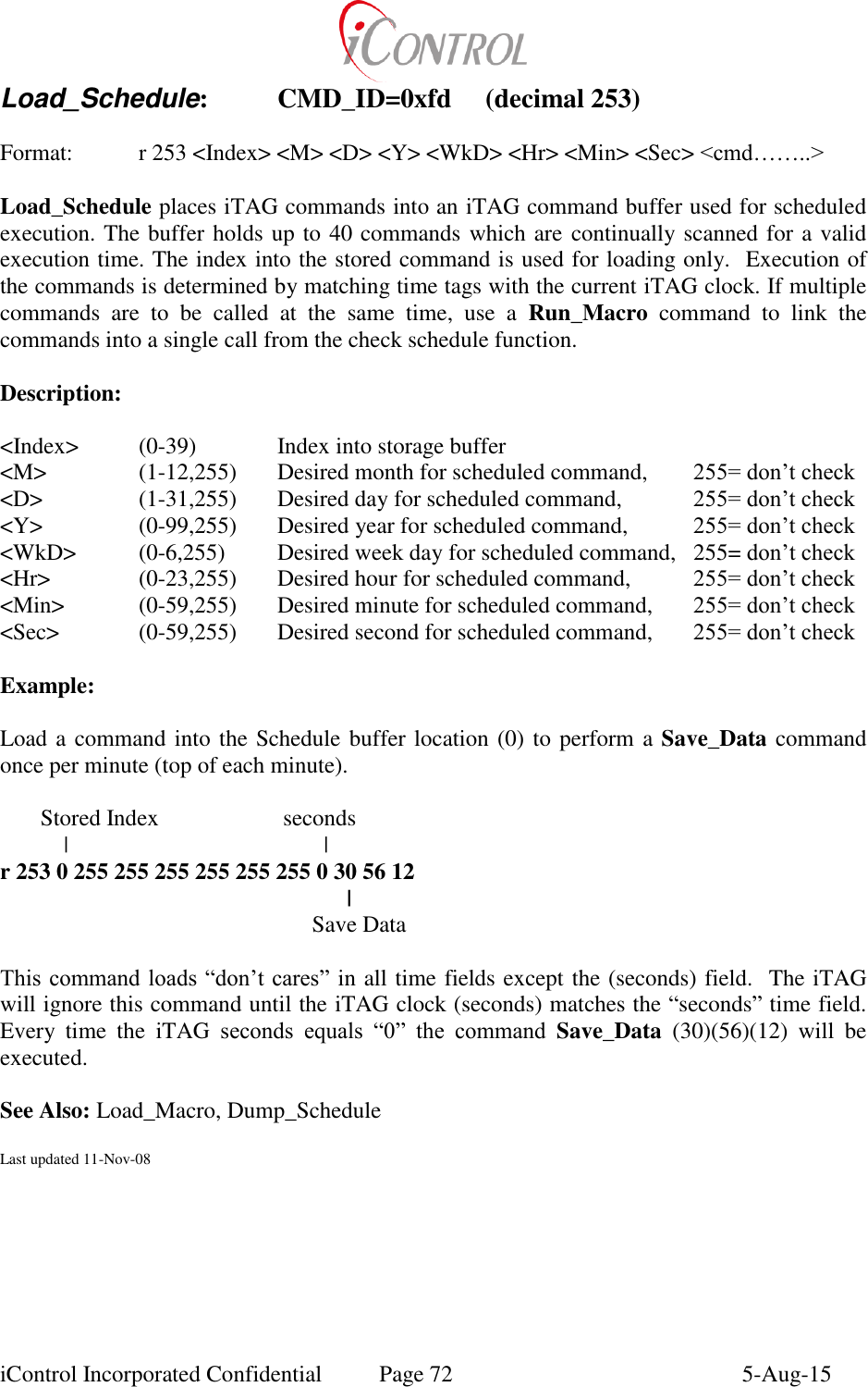
![iControl Incorporated Confidential Page 10 5-Aug-15 iTAG_ID: CMD_ID=0x03 (decimal 3) Format: r 3 <D3> <D2> <D1> <D0> [DeviceType] iTAG_ID sets the four byte iTAG identification number. This ID may also be programmed from the Setup Menu. (GEN2, GATE, RPT) Each iTAG should have a unique four byte address. Group calls for multiple iTAG’s may be achieved by setting Group Call ID’s via the Broadcast_Address command. This command also updates the first four bytes of the MAC_Addr with this entered iTAG_ID value. If DeviceType is included and it is ‘I’, ‘g’, or ‘G’, then the system Device Type variable is also updated. Description: <D3> Most Significant Byte of iTAG address <D2> <D1> <D0> Least Significant Byte of iTAG address [DeviceType] If ‘I’, ‘g’, or ‘G’, then system device type is updated. Example: Program new iTAG_ID (0.1.2.3) r 3 0 1 2 3 See Also: Broadcast_Address, Default_Dest, Server_Address, Commit_Flash Last updated 11-Nov-08](https://usermanual.wiki/Intelyt-orporated/ITAGV33/User-Guide-2730363-Page-13.png)
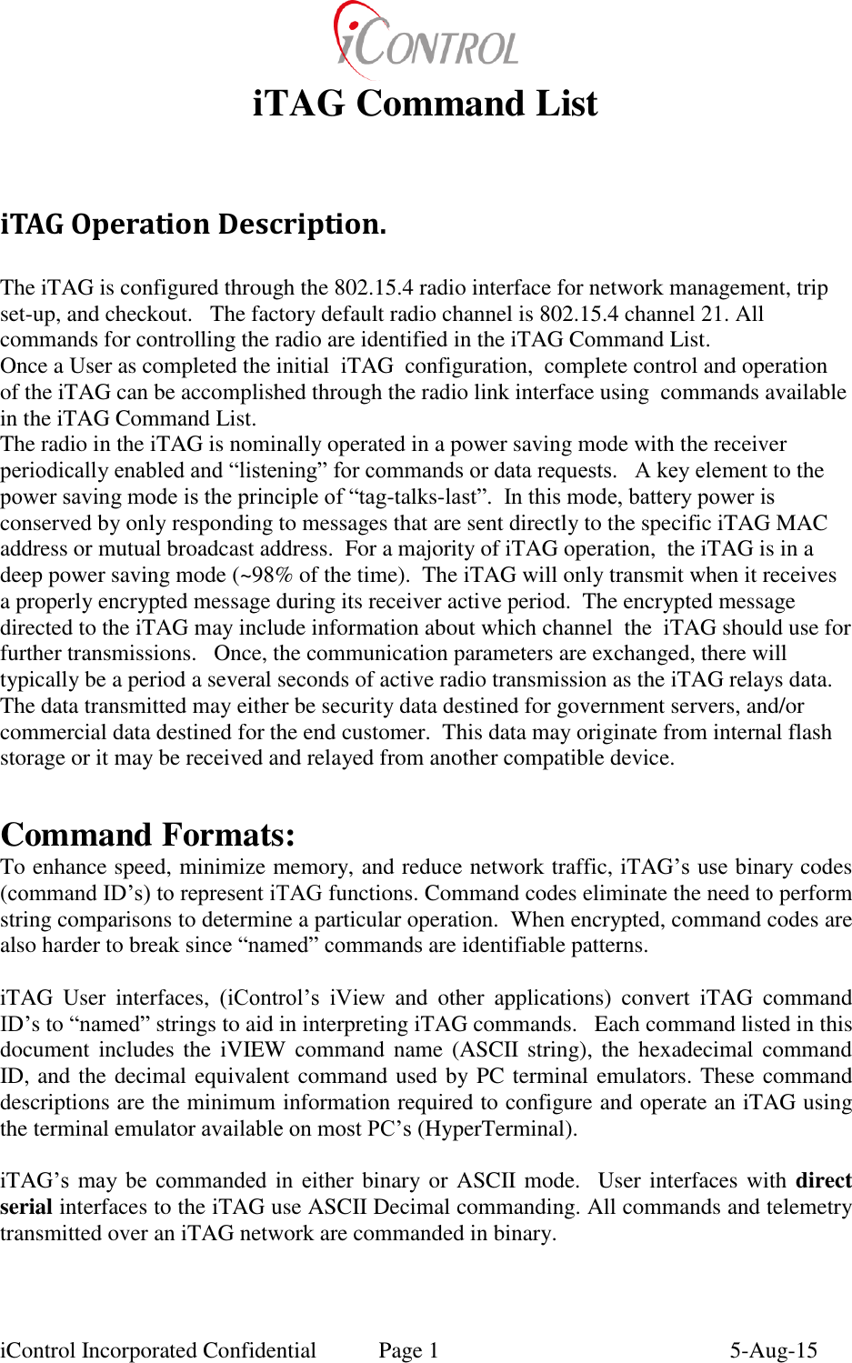
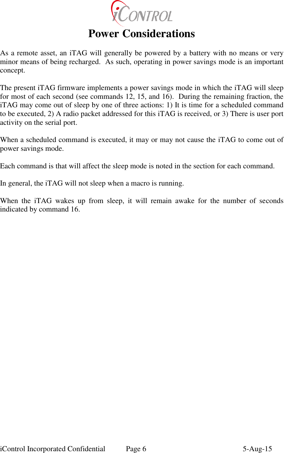
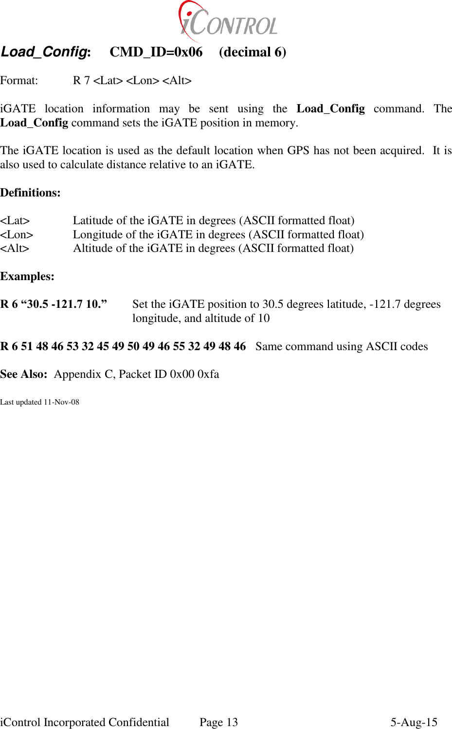
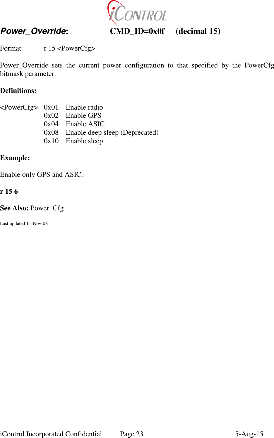
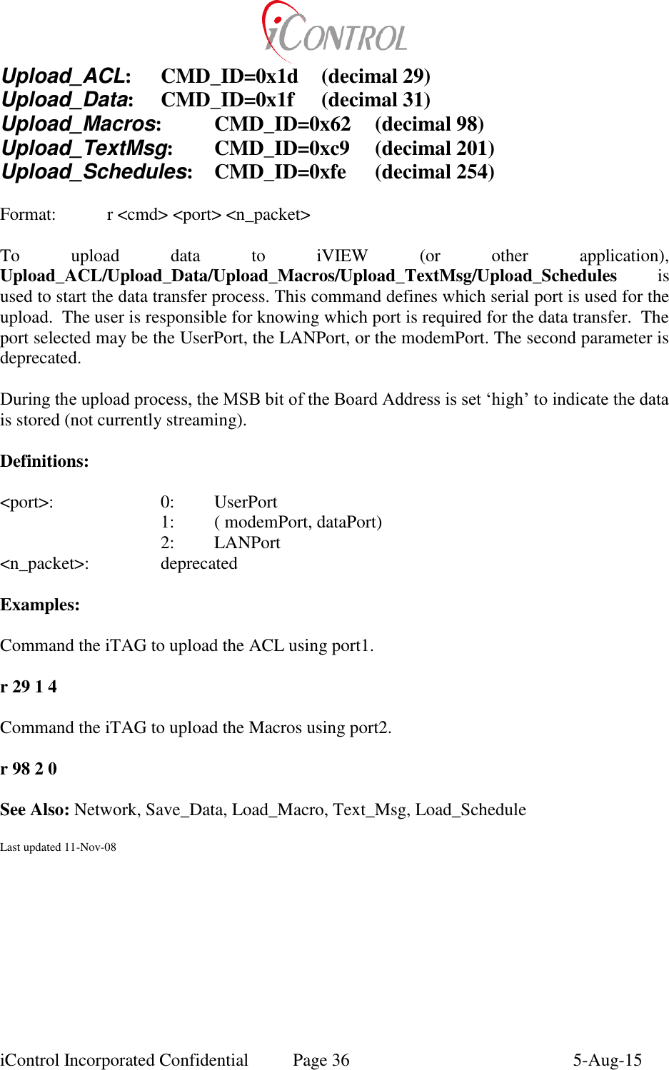
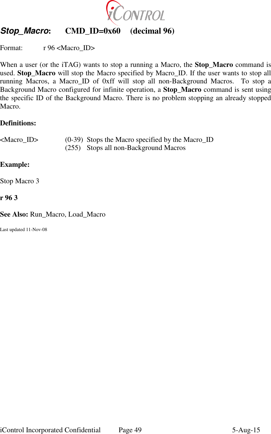
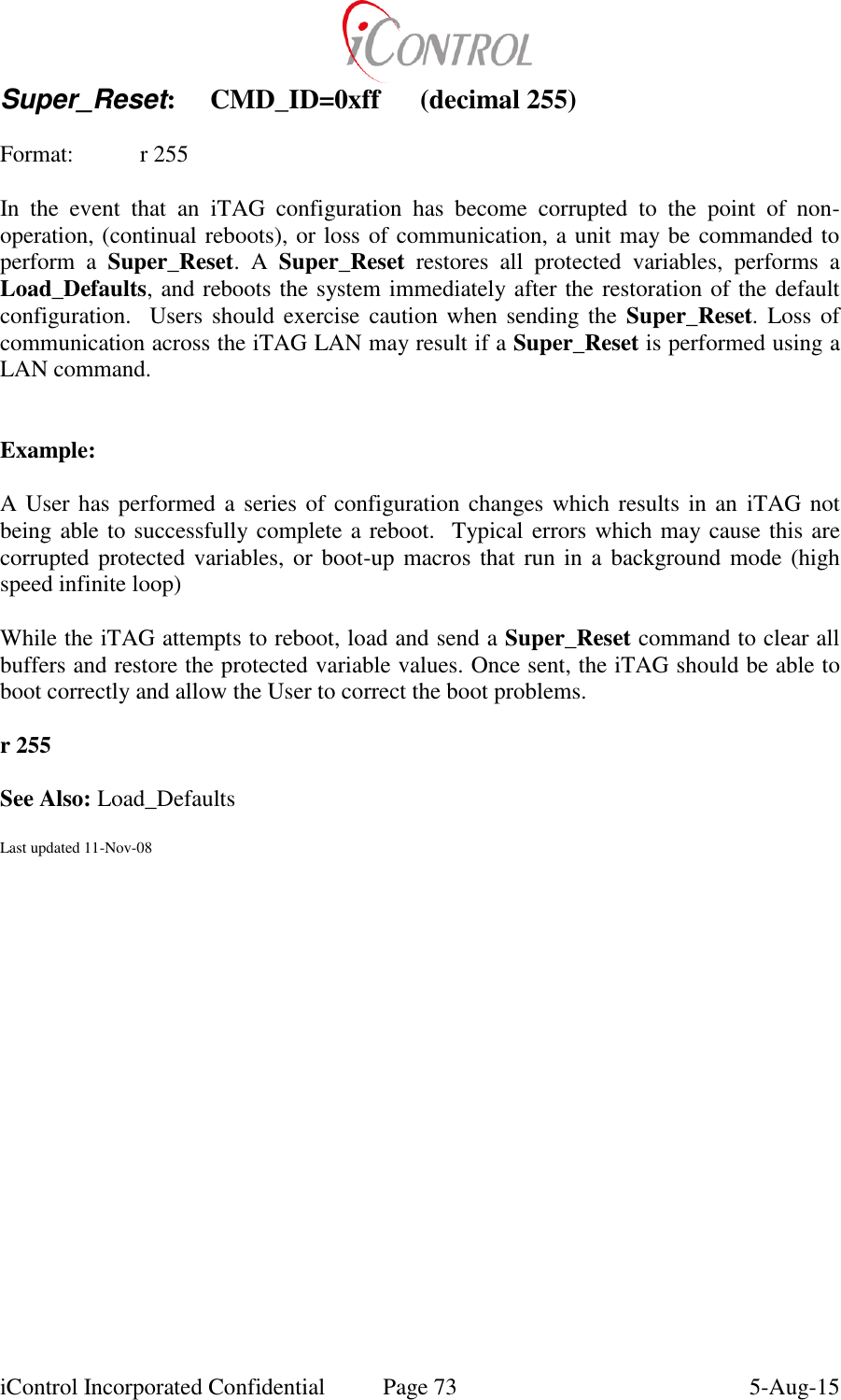
![iControl Incorporated Confidential Page 11 5-Aug-15 No_OP: CMD_ID=0x04 (decimal 4) Format: r 4 [D3] [D2] [D1] [Dn] An iTAG No_Op command is used to test the Network connection to an iTAG. Sending a No_OP command from one iTAG to another causes the receiving iTAG to respond to the Source ITAG with an ACK packet containing the iTAG_ID. A No_OP causes the iTAG to perform no other functions. Data appended to the end of the No_Op command can be used to perform a communication test. The user may send up to 236 bytes of data using the No_OP command. The returned ACK will append the user data to the end of the ACK. A failed CRC error will be written to the iTAG display if a communication error occurs. Examples: Send No_Op packet to iGate 0.0.0.0 This command is useful to establish whether a recently installed iTAG is connected to the iTAG LAN. When an installer sets up an iTAG, the No_OP command can be sent to the network iGATE while at the iTAG location. If networked, the iGATE will respond with an ACK packet to the iTAG. The installed iTAG will print to the screen that an ACK has been received from the iGATE. If available, the Radio signal strength will be displayed when the ACK is received. R 5 1 0 0 0 0 4 (standard No_OP command) R 5 1 0 0 0 0 4 1 2 3 4 5 6 7 8 9 10 11 12 13 14 15 16 (No_OP with test data) See Also: Forward_Packet Last updated 11-Nov-08](https://usermanual.wiki/Intelyt-orporated/ITAGV33/User-Guide-2730363-Page-14.png)
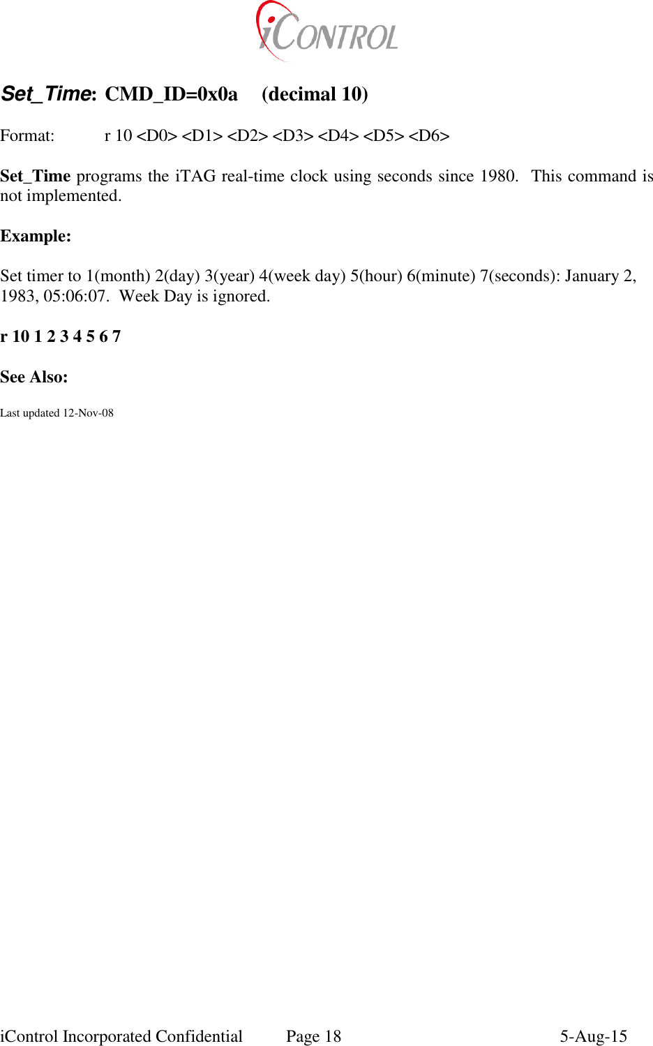
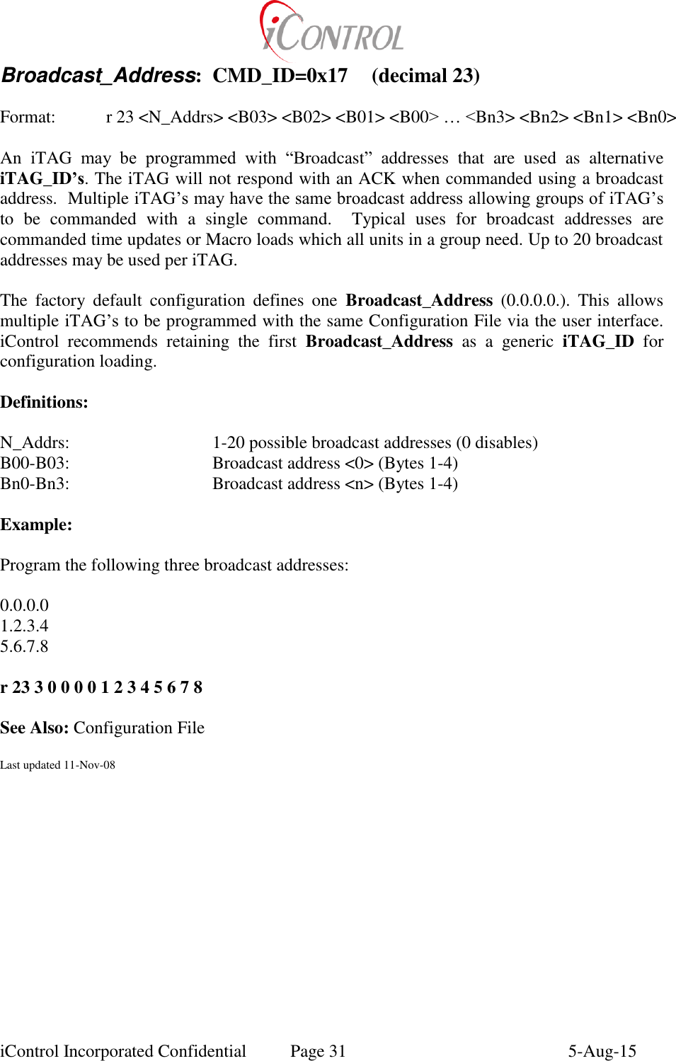
![iControl Incorporated Confidential Page 15 5-Aug-15 Network: CMD_ID=0x08 (decimal 8) Format: r 8 <Type> [Params] iTAG’s use an 802.15.4 radio for LAN communications. Network commands are used to configure the network. Definitions: Params <Type> ‘A’ Force association to specified state (‘l’, ‘L’, ‘N’, ‘S’, ‘W’) P0: association state P1: Comm (Association) timer value – stay associated P1 seconds ‘C’ Set Commissioned state P0: ‘Y’ or ‘N’: Commissioned state is Yes or No. See Test_Condition ‘D’ Action when beacon received from specified address P0: ‘E’-enable macro, ‘D’-disable, ‘C’-command enabled P1-P4: 4 byte address to check against beacon sender P5: Macro number for P0=‘E’, Command length for P0=’C’ P6: Command number for P0=’C’ P7-Pn: Command parameters for P0=’C’ ‘I’ Setup Internetworking for meshing ‘J’ Insert a unit into ACL (Join) P0-P7: 8 byte address to insert into the ACL P8: 0x80 or 0 indicates whether to use encryption or not when communicating with this unit P9: Non zero indicates that this unit has power saving enabled. Send wakeup packets to this unit before trying to communicate. ‘L’ Delete unit form the ACL (Leaving) P0-P7: 8 byte address of unit to remove from the ACL ‘R’ If address is different from destination ID, send an association request P0-P3: 4 byte address to send the association request to ‘T’ Set ACL Timer to specified value. Unit in ACL stay in ACL for this specified number of seconds P0: MSB of ACL timer (unsigned int) P1: LSB of ACL timer (unsigned int) Examples: r 8 ‘C’ ‘Y’ Set commissioned state to Yes r 8 ‘DC’ 14 0 0 1 3 249 10 11 Set DataByte[10]=11 when a beacon from 14 0 0 1 is received](https://usermanual.wiki/Intelyt-orporated/ITAGV33/User-Guide-2730363-Page-18.png)
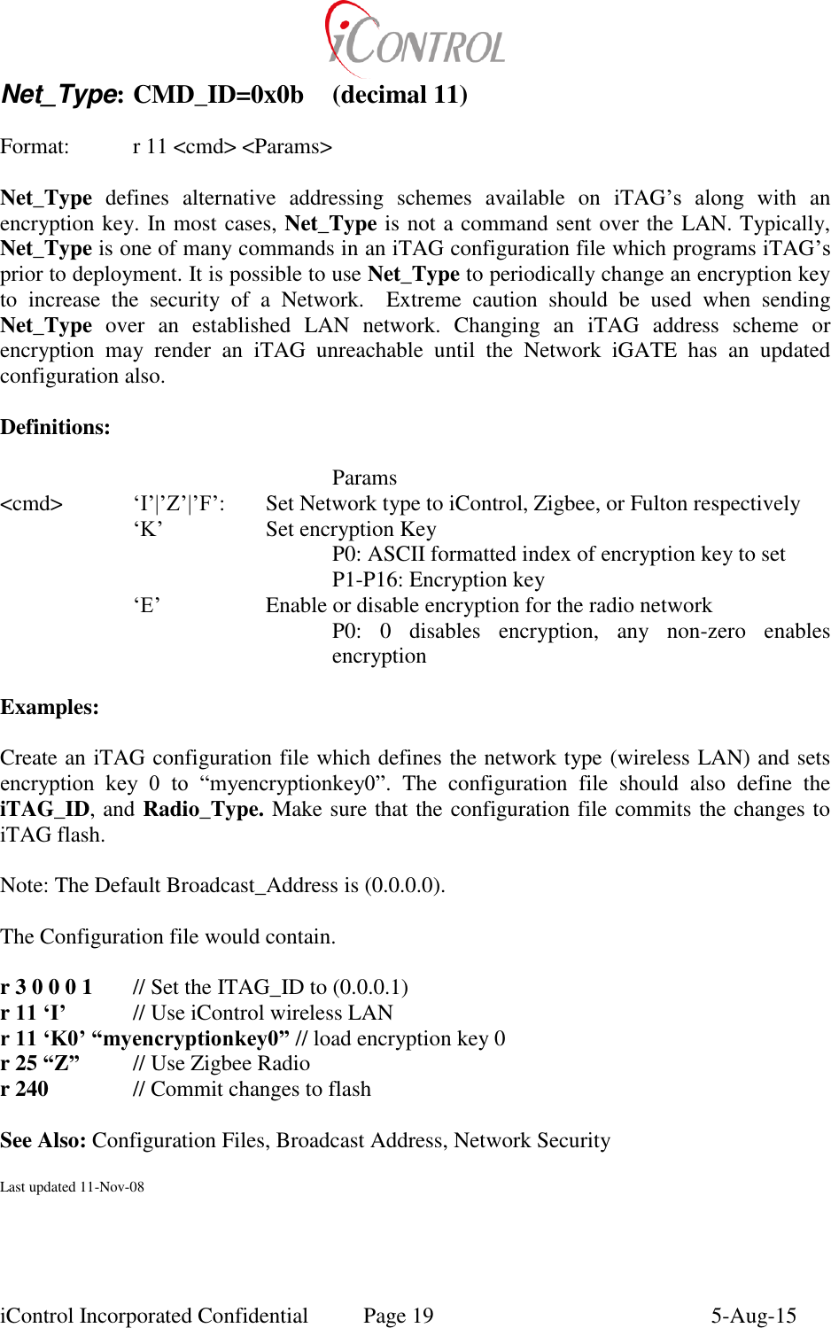
![iControl Incorporated Confidential Page 17 5-Aug-15 Port_CFG: CMD_ID=0x09 (decimal 9) Format: r 9 <port> <baud> <cfg> <function> [Param] Port_CFG remotely (or via a Macro) change a serial port configuration identified by <port>. Once the Port_CFG is executed, the specified port is re-initialized. The iTAG serial ports can be configured via the iTAG Setup Menu. (GEN2, GATE, RPT) Definitions: Param <port> Serial port to be changed (0-2) <baud> New baud rate, ranges from 1.2-115 Kbps (use baud/1200) <cfg> For Radio (port 2) specify radio parameters <function> 2: LANPort[0] 3: LANPort[1] 4: ModemPort 5: DataPort P0: ‘T’ or ‘F’, enables checking of this serial port as a user interface 6: LCD port ‘D’: Disable echo port (Not implemented) P0: Port number to be used as an echo port ‘E’: Set Echo Port (Not implemented) Example: Set Serial Port 1, to 57.6KBps, use for LANPort[1] R 9 1 48 0 3 See Also: Last updated 11-Nov-08](https://usermanual.wiki/Intelyt-orporated/ITAGV33/User-Guide-2730363-Page-20.png)

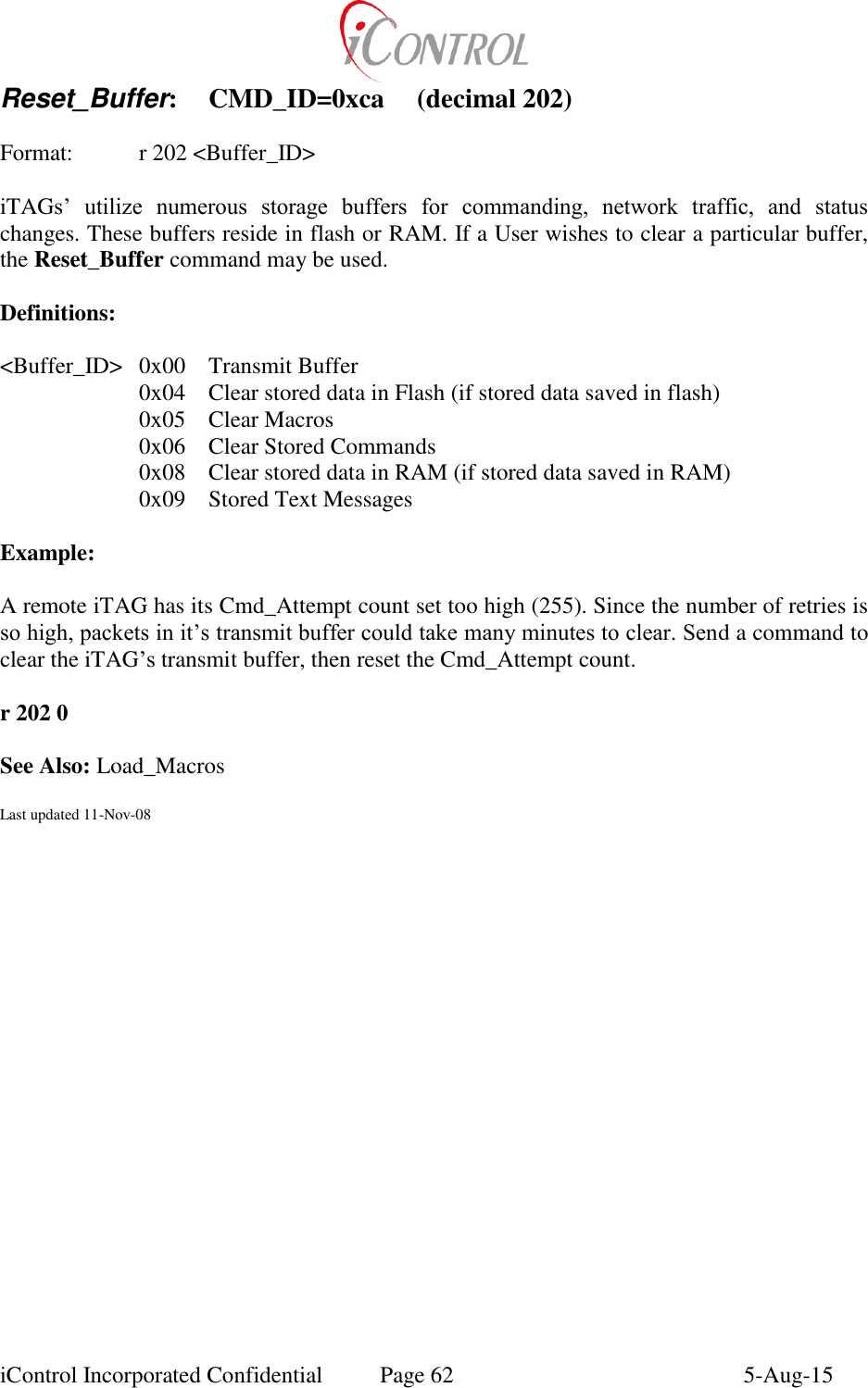
![iControl Incorporated Confidential Page 28 5-Aug-15 Hangup_Modem CMD_ID=0x14 (decimal 20) Format: r 20 [ModemState] For general usage, the Hangup_Modem command ends the present modem connection. In most cases, the ModemState is set to ‘S’ which will (shutdown) power down and disable the modem. For a PSTN modem, if the modem is connected, the iTAG may hang-up the modem and return to command mode using the Hangup_Modem command. The Hangup_Modem command is equivalent to the standard (AT modem command) ATH0. If the user wants to override the modem state (in the iTAG software), an optional parameter can be provided which controls the software state. This feature is useful for writing custom modem drivers using macros, or adapting the iTAG to unsupported modem types. Please Note: Overriding the modem state parameter does not control the external modem, only the iTAG firmware state machine is affected by the ModemState parameter i.e. (commanding ModemState=> Connect, does not mean the modem is connected. The iTAG with “think” it is connected) Definition: < ModemState > ‘I’: Initialize modem ‘C’: Modem State is connected ‘G’: Modem command mode, while online ‘R’: Modem state = ready ‘O’: Modem is offline ‘D’: Modem is dialing a number ‘A’: Modem is answering a call ‘X’: Modem is waiting for a connection ‘S’: Shutdown modem Example: Send command to hang up modem, then reconfigure modem to Answer any incoming call. r 20 // Hangup command r 18 1 // AT_Answer = 1; Enable Answer See Also: AT_Answer, AT_Dial, Phone_Number Last updated 11-Nov-08](https://usermanual.wiki/Intelyt-orporated/ITAGV33/User-Guide-2730363-Page-31.png)
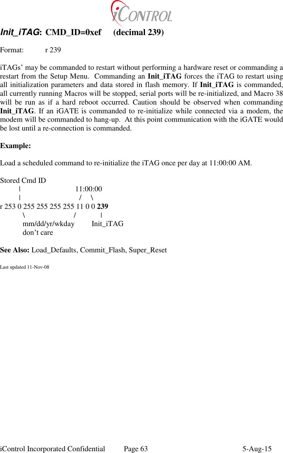
![iControl Incorporated Confidential Page 29 5-Aug-15 Enable_Schedule: CMD_ID=0x15 (decimal 21) Format: r 21 [Enable | Disable] The iTAG Operating System supports stored commands which are executed at User specified times. The stored commands utilize the clock/calendar function on the iTAG to determine when a scheduled command should be executed. Enable_Schedule is used to enable or disable the execution of stored commands. A User may wish to disable schedule checking to prevent an iTAG from “Hanging up” during a commanded connection. Definition: <Enable/Disable>: 0x01= Enable Schedule Checking 0x00= Disable Schedule Checking Example: r 21 1 Enable Schedule checking See Also: Load_Schedule, Dump_Schedule Last updated 11-Nov-08](https://usermanual.wiki/Intelyt-orporated/ITAGV33/User-Guide-2730363-Page-32.png)
![iControl Incorporated Confidential Page 30 5-Aug-15 Radio_Parameters: CMD_ID=0x16 (decimal 22) Format: r 22 <TXpreamble> <TXtail> <bSpacing> An iTAG configured with a LAN radio uses parameters to control the timing for transmit, receipt and RX mode. TXpreamble is deprecated and no longer used, but is reserved for future use. TXtail is the duration of time (milliseconds) that the iTAG waits before sending an ACK. bSpacing is used in the Delay_mSec command. Definitions: <TXpreamble>: Deprecated <TXtail>: 0-255 msec <bSpacing>: 0-255 msec * DataByte[0] to delay in Delay_mSec command Example: Set Radio parameters TXpreamble don’t care TXtail to 150 msec bSpacing 10 msec r 22 0 150 10 See also: Delay_mSec Last updated 11-Nov-08](https://usermanual.wiki/Intelyt-orporated/ITAGV33/User-Guide-2730363-Page-33.png)
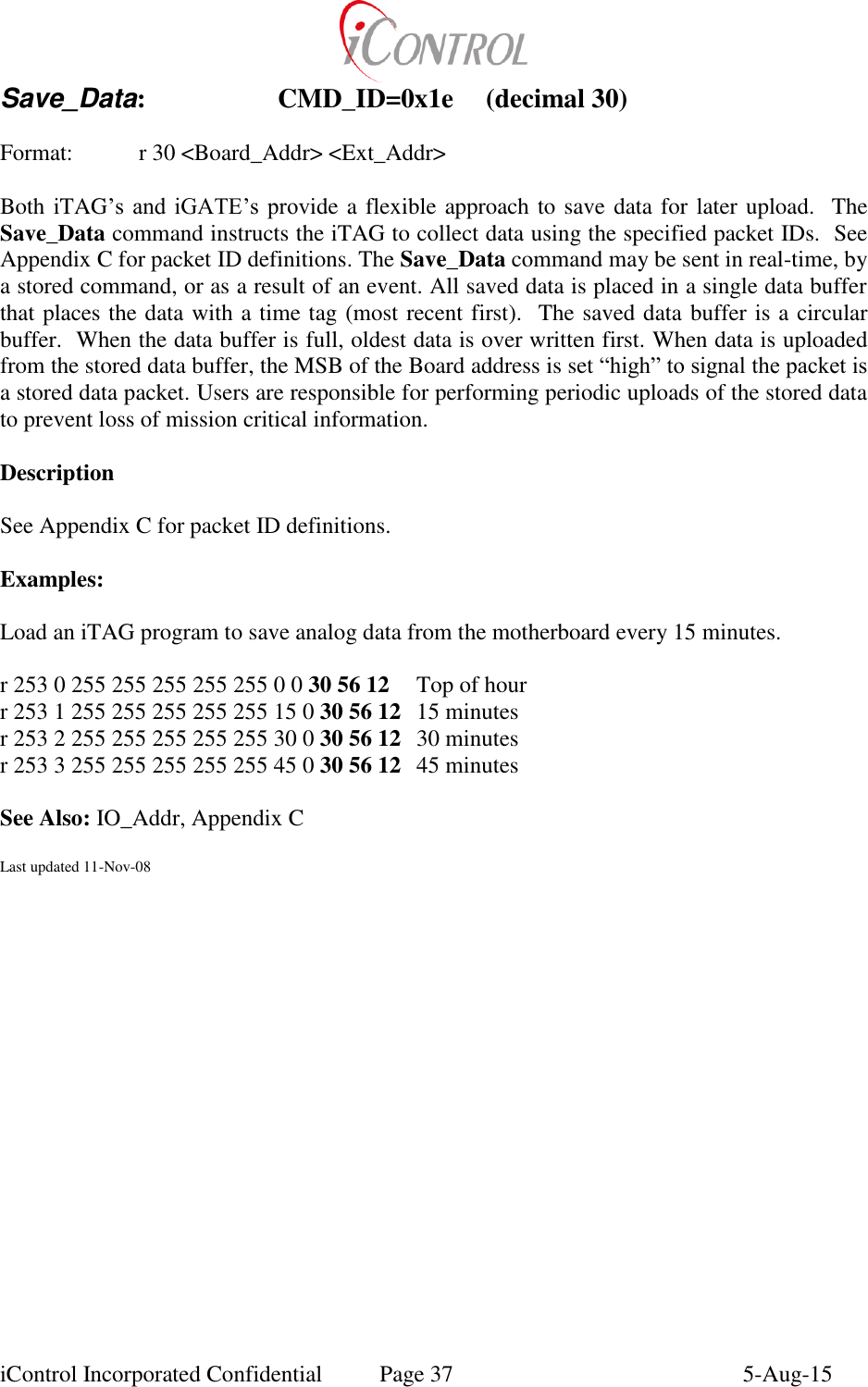
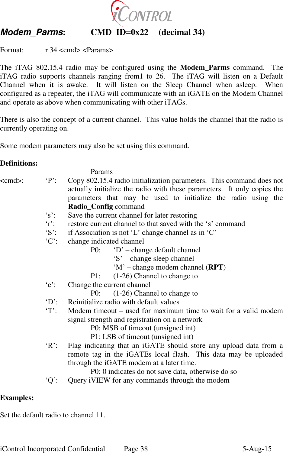
![iControl Incorporated Confidential Page 35 5-Aug-15 Password: CMD_ID=0x1c (decimal 28) Format: r 28 <p0><p1><p2><p3>…<pn> iTAG Set-Up and ASCII command functions may be password protected to prevent accidental or deliberate commands from being executed. Password can be sent remotely through the LAN or via the User Interface. The Password command is functionally the same as entering the Set-Up Menu using the iTAG login via the User Interface. The password is an ASCII alpha-numeric string with no more than 9 characters. Spaces and control characters are not allowed in the password. When the Password command is sent, both the Set Up menu and iTAG command processing functions are enabled. The string which accompanies the Password command is the iTAG password. Sending a zero length string disables both Set-Up Menu access and the command process functions. The Factory default password settings are: Password: “icontrol”. SET-Up Menu: Password Required ASCII Commanding: Access Permitted Examples: An iTAG has its password set to “yourword”. For security purposes, a User programmed Macro[38] sends the password command “0” effectively disabling Set-Up menu access and command processing. Send a command to the iTAG to re-enable ASCII commanding. r 28 “yourword” After the iTAG receives this command, access to the Set Up menu and command processing is enabled. When the user is ready to disable access, send a zero length Password command. R 28 Password may be used remotely to enable/disable iTAG access. See Also: Set_Password, Run_Macro,Load_Macro Last updated 11-Nov-08](https://usermanual.wiki/Intelyt-orporated/ITAGV33/User-Guide-2730363-Page-38.png)
![iControl Incorporated Confidential Page 41 5-Aug-15 Serial_R/W: CMD_ID=0x27 (decimal 39) Format: r 39 <R/W> <port> <data> iTAG’s may send or receive data via the serial ports to communicate with smart sensors. For most applications this operation is performed using the serial port configured as the DataPort. With this command, users define the parameters necessary to prompt MODBUS devices or PLC’s to return data for the iTAG to store or place in telemetry. Definitions: <R/W> (0) Sets message sync characters used for receiving data. There are 3 sync characters. Two start characters and a terminating character. (1) Write <serial message> bytes out specified port (2) Write contents of DataBytes out specified port (3) Reset specified serial port to flush receive buffer <port> 0-2 Serial port for data read write operations Examples: Prompt a GPS receiver to return data. Send appropriate prompt, wait 20 milliseconds, read data into a stored data packet. Assume: a) GPS receiver is hooked to serial port 2 b) “#<ENTER>” Generates data prompt c) Receiver needs 20 milliseconds to respond with data d) Start of returned data packet is a “&=”. e) The terminating character is <ENTER> Load Macro 0 with the following commands, (in a text file they are decimal) r 39 0 2 38 61 13 Sets the message sync and terminating characters r 39 1 2 35 13 Send the Prompt (ASCII decimal #,enter) r 102 20 Delay Macro[0] 20 milliseconds r 30 0 32 Read/save data string from serial port 2 (0x20=32) Each time the user wishes to save data from the GPS receiver, execute Macro 0 with a Run_Macro command. See Also: MS_Delay, Save_Data, Run_Macro Last updated 11-Nov-08](https://usermanual.wiki/Intelyt-orporated/ITAGV33/User-Guide-2730363-Page-44.png)
![iControl Incorporated Confidential Page 44 5-Aug-15 Track: CMD_ID=0x3e (decimal 62) Format: r 62 <Command> [params] Program Track mode and motion sense parameters. The motion sense parameters are used when the iTAG is equipped with an accelerometer. The accelerometer is checked once per second. If the magnitude of the accelerometer axis has changed more than MotionDetect, then increment a counter. If that counter is greater than MotionTimer, indicate that motion has occurred. This counter is reset with each 63 ‘M’ command. The track parameters are used to check for changes related to GPS. The 63 ‘T’ ‘P’ or the 62 ‘t’ ‘P’ command uses the TrackRange value to determine if the iTAG has moved greater than TrackRange meters from Waypoint[0]. Waypoint[0] is overwritten with the present location if the iTAG is greater than TrackRange meters from the previous Waypoint[0] value. The algorithm that uses the TrackVelocity, MovingFix, and StationaryFix is not implemented. The waypoints are used to calculate distance from the present position. These distances can then be formatted into a data packet and used in the Check_Alarm command. All parameters can be saved to non-volatile ram using the 240 command. (GEN2) Definitions: (Params) <Command> C Set Velocity counters (Not presently implemented) P0: Moving Fix MSB of unsigned int P1: Moving Fix LSB of unsigned int P2: Stationary Fix MSB of unsigned int P3: Stationary Fix LSB of unsigned int D Debug/Display parameters – only valid in DN display M Set motion sense parameters P0: Motion Detect MSB of unsigned int P1: Motion Detect LSB of unsigned int P2: Motion Timer MSB of unsigned int P3: Motion Timer LSB of unsigned int t Run track algorithm P0: P | V | T T Set Tracking parameters P0: Track Range (string formatted float) P1: Track Velocity (string formatted float) W Program waypoints P0: ‘C’ – clear all waypoints](https://usermanual.wiki/Intelyt-orporated/ITAGV33/User-Guide-2730363-Page-47.png)
![iControl Incorporated Confidential Page 45 5-Aug-15 P0: Index of waypoint to program P1: Waypoint Lat (string formatted float) P2: Waypoint Long (string formatted float) Example: Set Track Range to 500 meters and Track Velocity to 10.3 meters per second. r 62 ‘T’ “500. 10.3” r 63 84 53 48 48 46 32 49 48 46 51 Set waypoint 2 to 35.12 and -90.01 degrees r 62 ‘W’ 2 “35.12 -90.01” r 62 87 2 51 53 46 49 50 32 45 57 48 46 48 49 Set motion detect to 60 and motion timer to 301. r 62 ‘M’ 0 60 1 45 r 62 77 0 60 1 45 If DataByte[5]==8 and iTAG is associated and GPS is valid, execute macro 20, else do nothing. Note that the ‘x’ value in “G=x” is a don’t care as GPS is either valid or not and this state is not compared to any value that may be set in the firmware. r ‘?d58?A=L?G=xrM’ 20 99 r 63 100 5 8 63 65 61 76 63 71 61 120 114 77 20 99 See Also: Test_Condition, Check_Alarm Last updated 11-Nov-08](https://usermanual.wiki/Intelyt-orporated/ITAGV33/User-Guide-2730363-Page-48.png)
![iControl Incorporated Confidential Page 46 5-Aug-15 Test_Condition: CMD_ID=0x3f (decimal 63) Format: r 63 “<Object>=<Test>rM” <true Macro> <false Macro> Alternate: r 63 “<Object>=<Test>rC” <Command> Alternate: r 63 “d<Index><Value>rM” <true Macro> <false Macro> Alternate: r 63 “d<Index><Value>rC” <Command> iTAG’s have many conditions that may be tested for a certain condition. The Test_Condition command allows logic that will execute a certain macro if a condition is true and a different macro if the condition is false. Alternately, a command may be executed if the condition is true. Tests may be combined, where each test case will be checked in order. The true case is executed if and only if all test cases are true. Definitions: <Object>: iTAG state to be tested <Test>: State of Object for comparison <true Macro>: Macro to run if above comparison is TRUE <false Macro>: Macro to run if above comparison is FALSE <Command>: Command to run if above comparison is TRUE Object Description Possible States for Test A Is iTAG is associated in an 802.15.4 network l: transitory state, iTAG is about to become associated L: iTAG is associated with an iGATE n: transitory state, iTAG is about to become disassociated N: iTAG is not associated S: iTAG is scanning T: iCHIME is associated W: iGATE is associated in a Wide Area Network C Is iTAG commissioned N: iTAG has not been commissioned Any other 8-bit value can be commanded and therefore tested d Test if DataByte[Index]==value Any 8-bit value can be commanded and therefore tested for D Is there stored data None G Is GPS valid None M Has there been motion sensed N: no motion Y: motion has occurred](https://usermanual.wiki/Intelyt-orporated/ITAGV33/User-Guide-2730363-Page-49.png)
![iControl Incorporated Confidential Page 47 5-Aug-15 N Check for a change in the number of members in the ACL None t Check Track status, save data if true None T Check Track status None Power Considerations: If either true or false Macro is a valid macro and that macro will be executed, the iTAG is reset from power savings mode. If a command is to be executed, the power savings mode will be reset according to that specific command. Example: If iTAG is associated, execute macro 5, execute macro 6 otherwise. r ‘?A=LrM’ 5 6 r 63 65 61 76 114 77 5 6 If iTAG is associated, execute command to change mode to flow 5 samples. r ‘?A=LrC’ 1 5 5 r 63 65 61 76 114 67 1 5 5 If DataByte[5]==8, execute macro 20, else do nothing r ‘?d58rM’ 20 99 r 63 100 5 8 114 77 20 99 If DataByte[5]==8 and iTAG is associated and GPS is valid, execute macro 20, else do nothing. Note that the ‘x’ value in “G=x” is a don’t care as GPS is either valid or not and this state is not compared to any value that may be set in the firmware. r ‘?d58?A=L?G=xrM’ 20 99 r 63 100 5 8 63 65 61 76 63 71 61 120 114 77 20 99 See Also: Commissioned, Track, DataByte Last updated 11-Nov-08](https://usermanual.wiki/Intelyt-orporated/ITAGV33/User-Guide-2730363-Page-50.png)
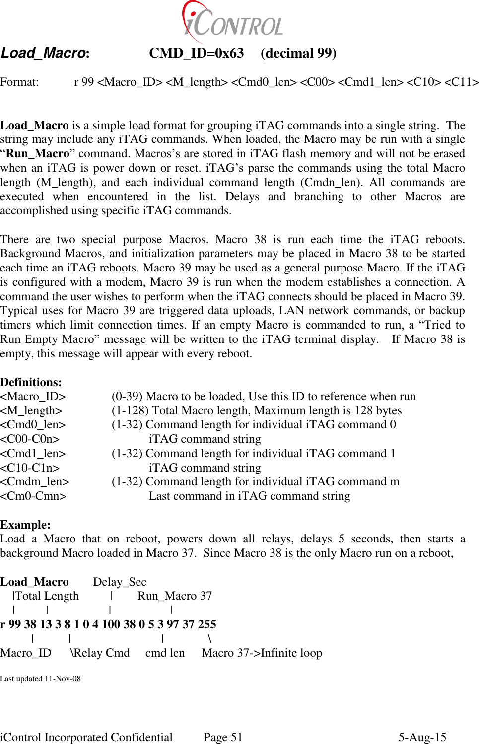
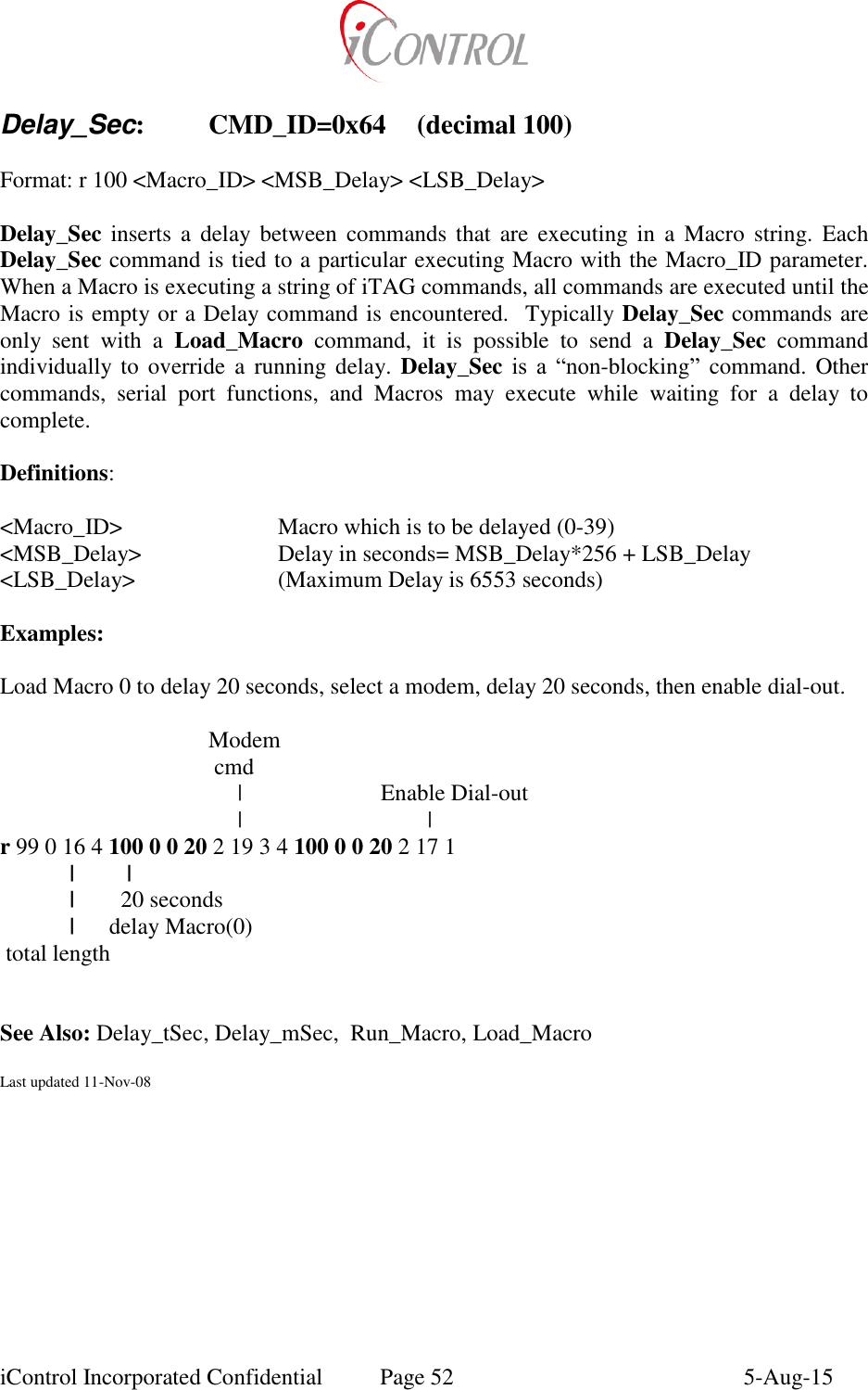
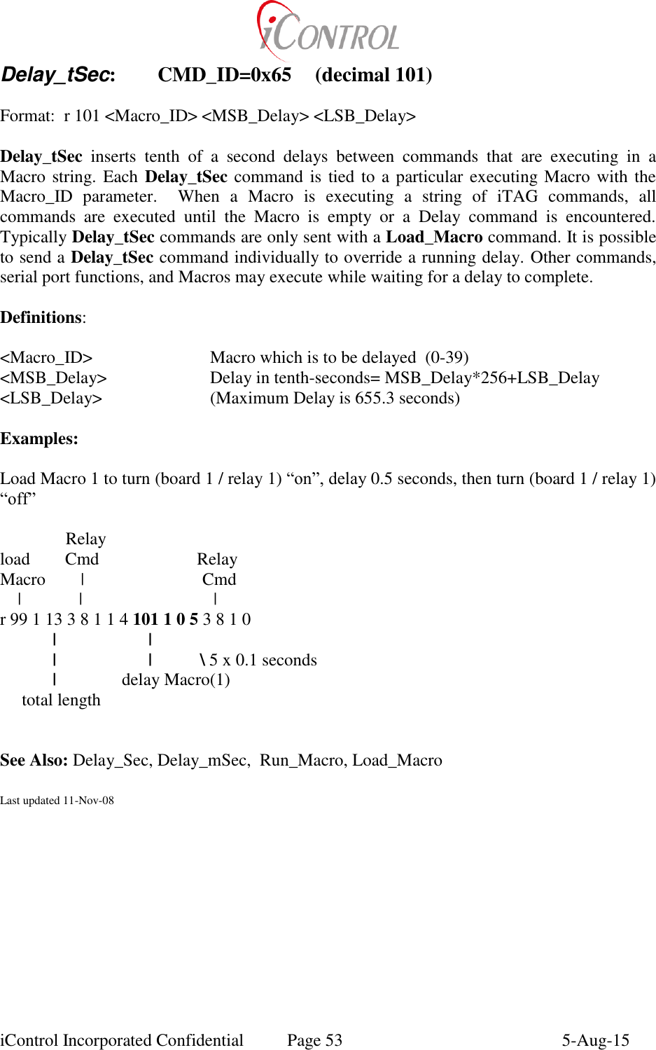
![iControl Incorporated Confidential Page 50 5-Aug-15 Run_Macro: CMD_ID=0x61 (decimal 97) Format: r 97 <Macro_ID> <Loop> A User, remote command, Alarm condition, or another Macro may be used to start a loaded Macro. Macro_ID is used to identify the desired Macro to run. Macros may be run multiple times using the Loop parameter at the end of the Run_Macro Command. A loop value of (255,<0xff>) causes the Macro to run in infinite Background mode. There are two special purpose Macros. Macro[38] is run each time the iTAG reboots. Background Macros and initialization parameters may be placed in Macro[38] to start each time an iTAG reboots. Macro[39] may be used as a general purpose Macro. If the iTAG is configured with a modem, Macro[39] is run when the modem establishes a connection. Any command the user wishes to execute when an iTAG modem connects should be placed in Macro[39]. Typical uses for Macro[39] are triggered data uploads, LAN network commands, or backup timers which limit connection times. If an empty Macro is commanded to run, an error message will be written to the screen. Definitions: <Macro_ID> (0-39) Runs the specified Macro <Loop> (0-254) Runs the specified Macro up to 254 times before stopping 255 Places Macro in an infinite loop (Background) Examples: Command Macro(0) to run 20 times. r 97 0 20 Command Macro(37) to run in Background mode. r 97 37 255 See Also: Last updated 11-Nov-08](https://usermanual.wiki/Intelyt-orporated/ITAGV33/User-Guide-2730363-Page-53.png)
![iControl Incorporated Confidential Page 54 5-Aug-15 Delay_mSec: CMD_ID=0x66 (decimal 102) Format: r 102 <MS_Delay> Delay_mSec inserts milli-second delays between commands that are executing in a Macro string. Delay_mSec commands are not tied to a particular Macro. When a Macro is executing a string of iTAG commands, all commands are executed until the Macro is empty or a Delay command is encountered. Delay_mSec commands are only sent with a Load_Macro command. Delay_mSec is a blocking command, other commands and Macros are suspended while Delay_mSec completes. Definitions: <MS_Delay> (1-50) Delay in milli-seconds (Maximum Delay is 50 milli-seconds) (>50) Delay is DataByte[0]*Bspacing seconds Examples: Load Macro 1 to turn (board 1/relay 1) “on”, delay 0.010 seconds, then turn (board 1/relay 1) “off” Relay Load Cmd Relay Macro | Cmd | | | r 99 1 11 3 8 1 1 2 102 10 3 8 1 0 | | \ | | 10 x 0.001 seconds | delay Macro total length See Also: Delay_tSec, Delay_Sec, Run_Macro, Load_Macro, Radio_Parameters, DataByte Last updated 11-Nov-08](https://usermanual.wiki/Intelyt-orporated/ITAGV33/User-Guide-2730363-Page-57.png)
![iControl Incorporated Confidential Page 55 5-Aug-15 Wait_While: CMD_ID=0x67 (decimal 103) Format: r 103 <Delay Macro “n”> <until Macro “m”> <timeout> Wait_While is a non-blocking delay command which holds execution of Macro_ID “n” until Macro_ID “m” completes. When a Macro is executing a string of iTAG commands, all commands are executed until the Macro is empty or a Delay command is encountered. Wait_While commands are only sent with a Load_Macro command. Serial port functions, commands, and Macros all execute while waiting for a delay to complete. A Wait_While command is placed in the Macro which is required to delay. Command processing will resume after the Macro_ID[m] is finished. The Wait_While command initiates a 65535 count 100 mSec delay for macro n (similar to a 102 n 255 255 command). Only one macro complete value is saved for each macro. The delay is only reset when macro m completes. A Stop_Macro command deletes the completion flag, but does not signal the waiting macro to continue. To illustrate these issues, say macro 5 is to wait for macro 6. If another Wait_While command is executed for macro 10 to wait for macro 6 before 6 completes, then macro 5 will delay until 655.35 seconds have expired because each macro can only signal one other macro after it has completed. Macro 10 will delay until macro 6 completes. If macro 6 is stopped, then both macro 5 and macro 10 will delay until each has waited for 655.35 seconds since their respective 103 commands was executed. There is no interaction when different macros are used for macro m, so macro 5 may wait for macro 6 and macro 10 may wait for macro 20. In each case, macro 5 and macro 10 will resume execution as expected when their respective macros complete execution. Alternately, m may be replace with ‘A’, ‘G’, or ‘U’. In each case, macro n will wait until the iTAG is Associated, GPS is acquired, or a data upload has completed. Only one macro is saved for each flag. That is, a 103 A 5 command will delay macro 5 until Associated or for timeout seconds whichever comes first. A subsequent 103 A 10 command that is executed while macro 5 is still waiting for the iTAG to become associated will cause macro 10 to delay until associated or for timeout seconds whichever comes first and macro 5 will only be waiting for the timeout second timeout and will not continue when the iTAG becomes associated. Furthermore, the associated and GPS delay states are checked every second. The upload complete delay is only terminated when an upload has ended. Definitions: < Delay Macro “n”> (0-39) Macro which will wait until Macro[m] completes < until Macro “m”> (0-39) Macro which is to be waited for completion Example:](https://usermanual.wiki/Intelyt-orporated/ITAGV33/User-Guide-2730363-Page-58.png)
![iControl Incorporated Confidential Page 56 5-Aug-15 Load Macro[4] which will start a second Macro(Macro[24]) . Macro[4] should wait until Macro[24] is complete, then save the resulting data. r 99 4 12 3 97 24 25 3 103 4 24 3 30 4 255 (waits until M24 completes) r 99 24 20 4 8 2 255 0 4 101 24 0 2 4 8 2 0 0 4 101 24 0 2 Load Macro [4] which will initiate a data upload and delay until that upload is complete or 60 seconds whichever comes first. r 103 4 ‘U’ 60 (waits up to 60 seconds until upload completes) See Also: Delay_Sec, Delay_tSec, Delay_mSec, Run_Macro, Load_Macro, Upload_Data Last updated 11-Nov-08](https://usermanual.wiki/Intelyt-orporated/ITAGV33/User-Guide-2730363-Page-59.png)
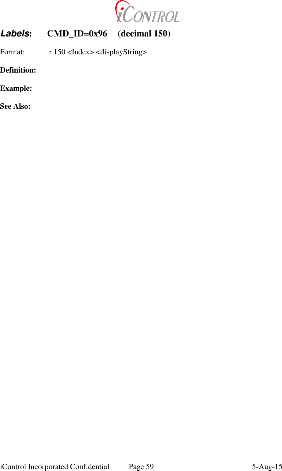

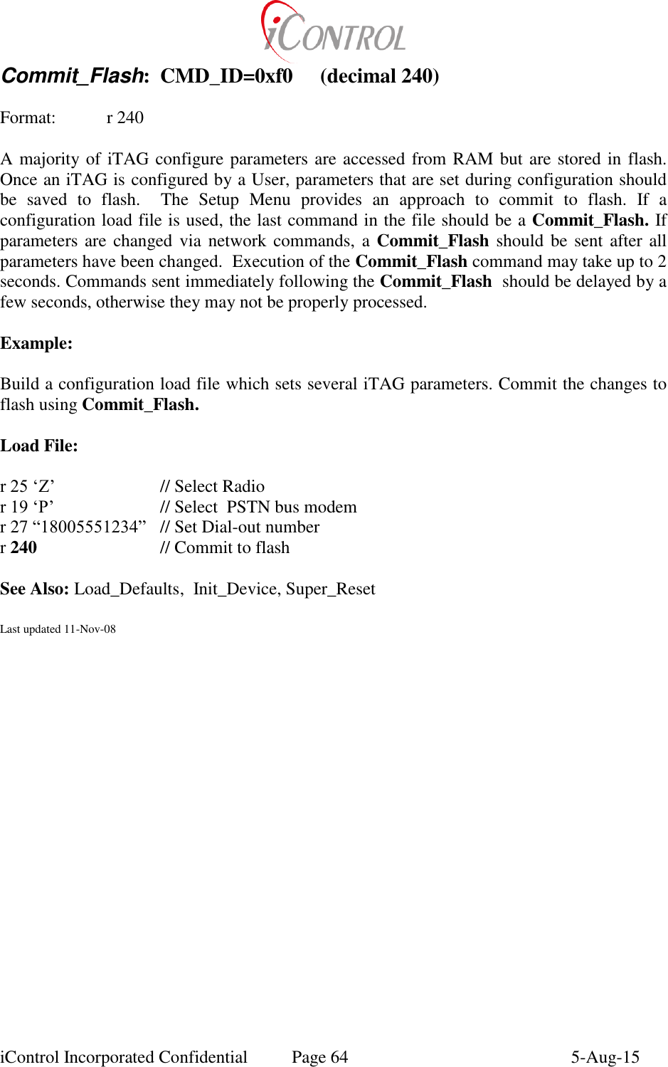
![iControl Incorporated Confidential Page 61 5-Aug-15 Text_Msg: CMD_ID=0xc8 (decimal 200) Format: r 200 [‘#’] <“Text String to be Sent”> Text_Msg is a command which places received text messages into battery backed RAM. The text message buffer is 20 bytes x 40 bytes. Each message is placed on a new line when a carriage return is encountered in the text message. The User at the receiving iTAG may review the text message by using the Text Message Display option. If the first byte after command 200 is a ‘#’ character, then program the unit ID instead of the Text Message. Definition: “Text String” Any ACSII character string not exceeding 40 characters per line String should terminate with a carriage return. Example: Send a text message. r 200 “ET Phone Home!” See Also: Last updated 11-Nov-08](https://usermanual.wiki/Intelyt-orporated/ITAGV33/User-Guide-2730363-Page-64.png)
![iControl Incorporated Confidential Page 68 5-Aug-15 DataByte: CMD_ID=0xf9 (decimal 249) Format: r 249 <Index> <Value> [Params] iTAG’s provide a global data structure which may be used to build user specified data packets. DataByte is a 40 byte structure which may be loaded with data which is sent, received, or alarmed. The DataByte command is used to set the value of a particular Databyte, or if requested, increment or decrement the current DataByte value. A User should make sure that other Macro’s or commands are not affecting the use of a particular DataByte. Definitions: <Index> (0-39) Index identifying which DataByte[] to modify <Value> ‘+’ Current value of DataByte[index] is incremented by one ‘-‘ Current value of DataByte[index] is decremented by one ‘s’ Copy command Params starting at DataByte[Index] to DataByte[Index + number of Params] ‘c’ copy Packet data into DataByte[Index] P0-P1: Packet ID bytes (see Appendix C) P2: start byte in above data packet to start copy from P3: number of bytes to copy (0-255) If an integer is sent, DataByte[index] will be assigned the new value) Example: Use DataByte[3] as an internal counter that is incremented every time Macro [4] is run. Load into Macro[4]: r 99 4 ”Macro Commands……” 249 3+ See Also: Load_Macros, Run_Macros Last updated 11-Nov-08](https://usermanual.wiki/Intelyt-orporated/ITAGV33/User-Guide-2730363-Page-71.png)
![iControl Incorporated Confidential Page 69 5-Aug-15 Check_Alarm: CMD_ID=0xfa (decimal 250) Check_Alarm_Save: CMD_ID=0xfb (decimal 251) Format: r 250 <Board Add> <Extended Add> <Index> <Op> <value> [value2] <Macro_ID> Scheduled or background commands may be used to check iTAG input data or system configuration for alarm conditions (or desired events). Check_Alarms retrieves data using the specified Board Address and Extended Address, performs a comparison using the Op character against the value parameter. If the Op condition is met, Macro[Macro_ID] will be run once. The Check_Alarm_Save command saves the retrieved data if the Op condition is met. Definitions: <Board Add> IO card address (See IO_Add) <Extended Add> IO card address (See IO_Add) 5, 250, 251: copy native floating point for test value 83, 254: copy one byte into floating point test value Default: format floating point test value using sFactors[Index] (See Scale_Factors) <Index> 0-12 Data[index] is value to be checked <Op> > Runs Macro[ID] if Data[index]>value < Runs Macro[ID] if Data[index]<value = Runs Macro[ID] if Data[index]=value ! Runs Macro[ID] if Data[index]!=value “A” Run Macro[ID] if Data[index] < value && Data[index] > value2 “O” Run Macro[ID] if Data[index] & value || Data[index] > value2 “&” Run Macro[ID] if Data[index] & value “|” Run Macro[ID] if Data[index] | value <value> “Threshold” value which triggers Macro[ID] <value2> Second Threshold value <Macro_ID> ID of Macro which is run on an alarm condition Examples: Load Macro[37] with a Check_Alarm command that calls Macro[36]. Macro[37] will be a Background Macro which checks data once per second. The Check_Alarm command executes when motherboard analog[1] is greater than value “128”. Default scale factors are used which indicate to use counts for comparison. r 99 36 7 3 96 37 2 17 1 Stop Macro[37], Enable Dialout r 99 37 13 4 100 37 0 1 7 250 56 12 1> 128 36 Check_Alarm r 99 38 3 97 37 255 Runs Macro[37] on boot up. Loop counter 255 places Macro[37] in an infinite loop](https://usermanual.wiki/Intelyt-orporated/ITAGV33/User-Guide-2730363-Page-72.png)
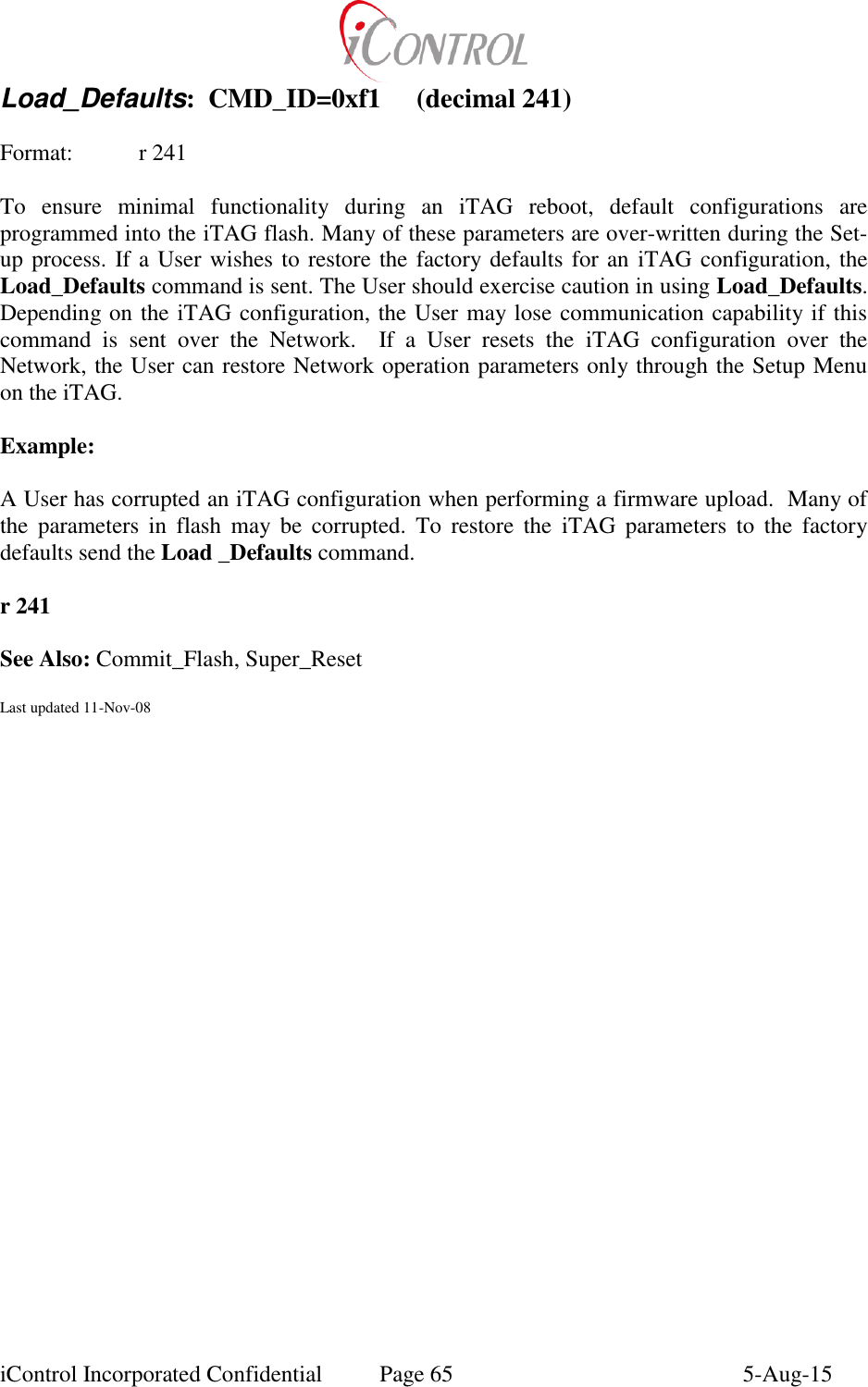
![iControl Incorporated Confidential Page 74 5-Aug-15 Appendix A Security: Password Protection: The only level of protection available for ASCII commanding is password protection. The factory default protection allows password access for the Set-Up Menu and open access to ASCII commanding. To enable password access for commanding, the User should load and enable a “Null” Password command in the boot up Macro (Macro[38]). Once the iTAG is rebooted, password protection will be enabled. When password protection is set, a Password command must be sent prior to sending any ASCII command. The Password command enables commanding until a “Null” Password command is sent, the iTAG reboots, or until a Stored Command executes a “Null” Password. Encryption: A majority of the wireless devices iControl provides include built in encryption. These devices enable a DES encryption algorithm independent of the iTAG OS setting. Setting the radio encryption key is covered by the Radio Manufacturers User Manual included with your purchase. In addition to the radio encryption, iControl offers both LAN and iGATE encryption algorithms that may be used over cellular and satellite links. iControl ships each iTAG unit with encryption disabled (a zero encryption key). Use the Net_Type command to set the iTAG OS encryption key. In addition to the encryption key, Users should be aware of Time_Window. Time_Window specifies the valid duration of time for an iTAG command. Time_Window reduces the possibility of recorded (even if encrypted) commands being recorded and played back by un-authorized parties. See Also: Password, Set_Password, Time_Window, Net_Type](https://usermanual.wiki/Intelyt-orporated/ITAGV33/User-Guide-2730363-Page-77.png)
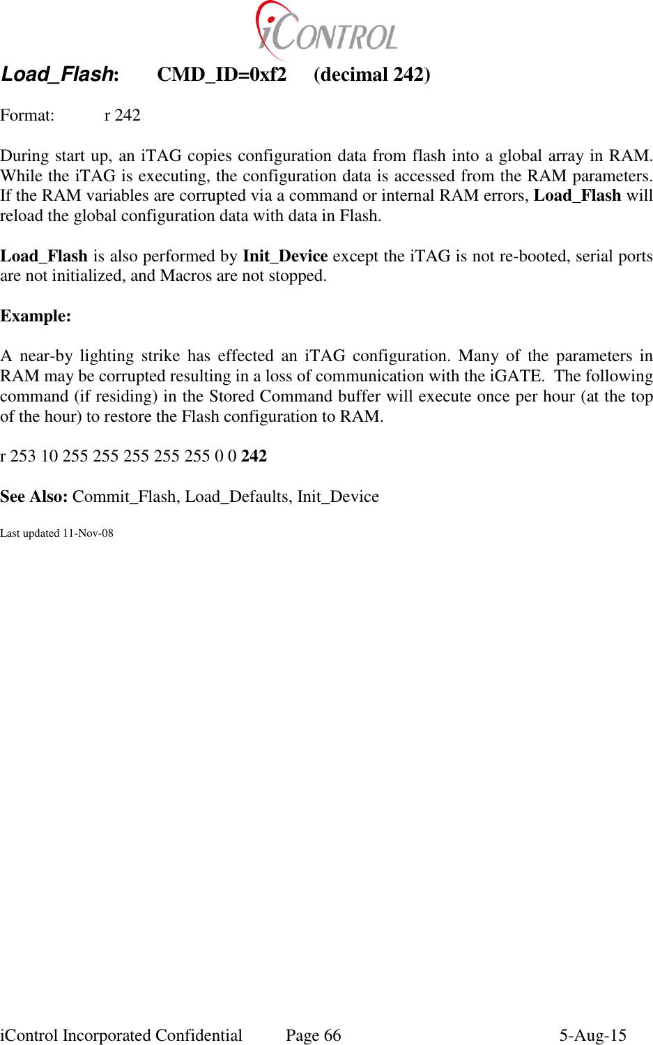
![iControl Incorporated Confidential Page 75 5-Aug-15 Appendix B Cyclical Redundancy Code (CRC): The following ‘C’ source code may be utilized by Users to develop binary protocols for interfacing to iTAG’s and iGATE’s. Two bytes are returned which represent the 16 bit CRC for any input string. iTAG’s apply CRC’s to all binary communication packets. void getCRC(char *buf, int len, char *value) { //CCITT CRC // buf: pointer to string which is to have CRC computed // len: Number of bytes in buf which are used for CRC computation // value: Two bytes representing 16 bit CRC // unsigned int crcval, temp; int i; crcval = 0xffff; for (i=0; i<len; ++i) { temp = crcval ^ (unsigned int)buf[i]; temp = (temp ^ (temp << 4)) & 0xff; crcval = (crcval >> 8) ^ (temp << 8) ^ (temp << 3) ^ (temp >> 4); } crcval = ~crcval; value[0]= (char)(crcval & 0x00ff); // return LSB (sent first) value[1]= (char)((crcval & 0xff00)>>8); // return MSB (sent second) }](https://usermanual.wiki/Intelyt-orporated/ITAGV33/User-Guide-2730363-Page-78.png)
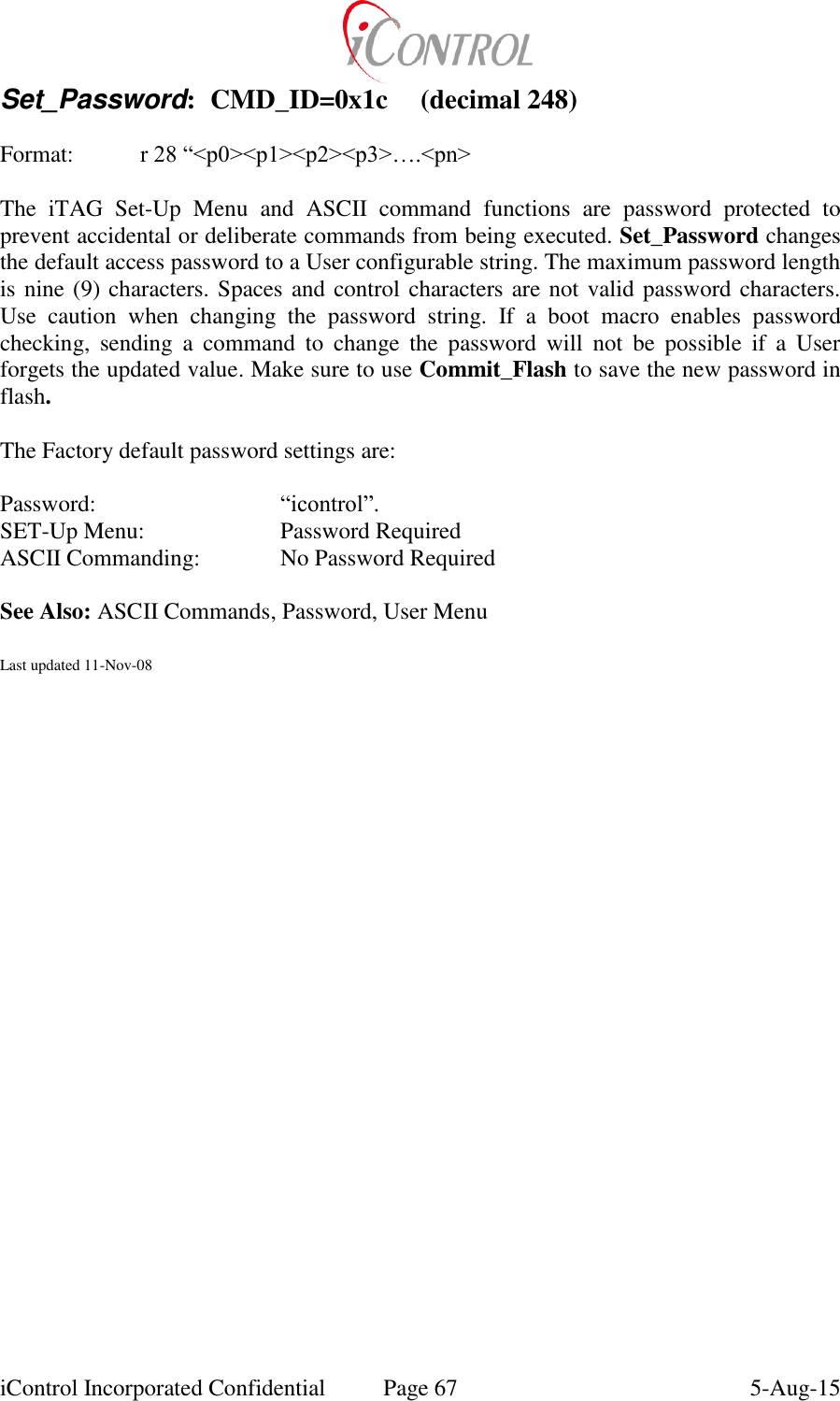
![iControl Incorporated Confidential Page 3 5-Aug-15 Byte 42-44 45 46 47 48 49 Baud rate of ports 0,1,2. Value=Baud/12 Reserved for future use Tpreamble/4 Not Used TXTail (Radio_Parameters) Present radio channel (Modem_Parms) Nav Mode. See Chip doc Byte 50 51 52 53 54 55 Power_Save Wake Power Config (Power_Config) Sleep Power Config (Power_Config) Present Power Config (Power_Config, Power_Override) Radio Status Byte. See chip doc Lower 8 bits of comm. Timer Byte 56 57 58 59 60 61 Reboot counter – incremented with each soft reboot TX_Attempts (CMD_Retry) TX Retry Time (CMD_Retry) Default Channel (Modem_Parms) Sleep Channel (Modem_Parms) Primary Radio (LAN_Device) Byte 62 63 64 65 66 67 Alt Radio Enable_Schedule Modem_Type Modem State AT_Answer AT_Dial Byte 68 69 70 71 72-76 77,78 Data Port User Interface flag (Port_Cfg) Flag indicating flash has been initialized Network ‘E’: Encryption enabled ‘N’: Disabled Bit mask indicating Macro is running or not ACL Timer (native unsigned int format) Packet ID 0x00 0x17 Broadcast IDs set with command 23 Length: 12 + (4*<number of broadcast groups>) Byte 12 13-16 [13+(n*4)] – [16+(n*4)] Number of valid Broadcast groups (n) Broadcast Group 1 Broadcast Group n Packet ID 0x00 0x22 Radio initialization parameters set with command 34 Length: 29 Packet ID 0x00 0x1b Telephone number used for modem communication. Number starts at byte 12. Length does not include null terminator. Length: 11 + length of telephone number Packet ID 0x00 0xfa](https://usermanual.wiki/Intelyt-orporated/ITAGV33/User-Guide-2730363-Page-81.png)
![iControl Incorporated Confidential Page 4 5-Aug-15 Difference between present GPS position and last recorded iGATE position. GPS solution must be valid, otherwise length of data packet is zero. Length: 42 Byte 12-15 16-19 20-23 24-27 28-31 32-35 36-39 40,41 42 Difference in meters between iGATE latitude and latitude of present location Difference in meters between iGATE longitude and longitude of present location Altitude – indeterminate value Northern Velocity as measured by present GPS solution Eastern Velocity as measured by present GPS solution Downward Velocity as measured by present GPS solution Magnitude of distance between iGATE position and present location in meters. Ignores Altitude. GPS Nav Mode. See Chip documentation for description. Radio LQI Packet ID 0x00 0xfb Packet ID 0x00 0xfc GPS position. If GPS solution is invalid and associated with an iGATE, report the iGATE position. If GPS solution is invalid and not associated with an iGATE, length of data is zero. Length: 42 Byte 12-15 16-19 20-23 24-27 28-31 32-35 36-39 40,41 42 Lattitude in degrees Longitude in degrees Altitude Northern Velocity as measured by present GPS solution Eastern Velocity as measured by present GPS solution Downward Velocity as measured by present GPS solution Magnitude of the present velocities GPS Nav Mode. See Chip documentation for description. Radio LQI Packet ID 0x00 0xfc (Deprecated) Floating point State Variables Length: 42 Packet ID 0x00 0xfe DataByte variables. . The value of DataByte[0] defines the number of DataByte values to output in this packet. Length: 11 + DataByte[0]](https://usermanual.wiki/Intelyt-orporated/ITAGV33/User-Guide-2730363-Page-82.png)
![iControl Incorporated Confidential Page 5 5-Aug-15 Byte 12 … 12+DataByte[0] DataByte[1] DataByte[DataByte[0]] Packet ID 0x20 0xXX (Deprecated) Address of parallel processor connected via serial port Packet ID 0x01 0xNN Packet ID 0x30 0xNN (Deprecated) Packet ID 0x38 0xNN Status information including Analog-to-Digital converter data. NN defines the number of bits in each 2-byte A/D value. This NN value is only used when decoding the A/D values as it records the maximum counts for the A/D values, it is not used by internal firmware. Although the connections to the individual A/D channels is totally dependent on hardware connections, A8 (A0 being the first channel) is connected to a voltage divider indicating the voltage powering the unit. Length: 42 Byte 12-35 36 37 37 37 38 39 40 41 42 12 channels of A/D data (2-bytes each) Reboot counter – incremented with each soft reboot Lower 5 bits of comm. timer Bit 6 – flag indicating in range of an 802.15.4 radio network Bit 7 – flag indicating that there is stored data Clock source 0: SW 1: RTC 2: GPS Last DataByte value Radio LQI Last RSSI indicated from an attached modem ‘N’ - not commissioned ‘Y’ – commissioned Last updated 12-Nov-08](https://usermanual.wiki/Intelyt-orporated/ITAGV33/User-Guide-2730363-Page-83.png)