MobileView Fleet Manager User Manual
2015-09-28
: InterLogix Fleet Manager User Manual Fleet Manager User Manual mobileview-training resources
Open the PDF directly: View PDF ![]() .
.
Page Count: 64
- Summary
- Content
- About this manual
- Product overview
- Features
- System requirements
- Other requirements
- Installing AutoArchiver
- Installing Fleet Manager
- Starting AutoArchiver
- Starting Fleet Manager
- Exiting AutoArchiver
- Exiting Fleet Manager
- Fleet Management System window
- Connecting to depot servers
- Configuring the system
- Working with Fleet Manager
- Fleet maintenance
- Troubleshooting
- Contacting us
- Online resources

MobileView Fleet Manager
User Manual
P/N 1056729 • REV E • ISS 08DEC10
Copyright © 2010 UTC Fire & Security. All rights reserved.
Disclaime
r
The information in this document is subject to change without notice.
UTC Fire & Security, Inc. assumes no responsibility for inaccuracies
or omissions and specifically disclaims any liabilities, losses, or risks,
personal or otherwise, incurred as a consequence, directly or
indirectly, of the use or application of any of the contents of this
document. For the latest documentation, contact your local supplier
or visit us online at www.interlogix.com.
This publication may contain examples of screen captures and
reports used in daily operations. Examples may include fictitious
names of individuals and companies. Any similarity to names and
addresses of actual businesses or persons is entirely coincidental.
Trademarks and
patents The MobileView Fleet Manager name and logo are trademarks of
UTC Fire & Security.
GE and the GE monogram are trademarks of the General Electric
Company and are under license to UTC Fire & Security, 9 Farm
Springs Road, Farmington, CT 06034-4065, USA
Other trade names used in this document may be trademarks or
registered trademarks of the manufacturers or vendors of the
respective products.
Manufacture
r
UTC Fire & Security Americas Corporation, Inc.
2955 Red Hill Avenue, Costa Mesa, CA 92626-5923, USA
Version This document applies to MobileView Fleet Manager PENTA.
Intended use Use this product only for the purpose it was designed for; refer to the
data sheet and user documentation for details. For the latest product
information, contact your local supplier or visit us online at
www.interlogix.com.
FCC compliance This equipment has been tested and found to comply with the limits
for a Class A digital device, pursuant to part 15 of the FCC Rules.
These limits are designed to provide reasonable protection against
harmful interference when the equipment is operated in a
commercial environment. This equipment generates, uses, and can
radiate radio frequency energy and, if not installed and used in
accordance with the instruction manual, may cause harmful
interference to radio communications.
You are cautioned that any changes or modifications not expressly
approved by the party responsible for compliance could void the
user's authority to operate the equipment.
Contact information For contact information, see www.interlogix.com.
MobileView Fleet Manager User Manual i
Content
Chapter 1 Introduction 1
About this manual 2
Product overview 2
Features 3
System requirements 3
Other requirements 4
Chapter 2 Installation 5
Installing AutoArchiver 6
Installing Fleet Manager 8
Chapter 3 Using Fleet Manager 11
Starting AutoArchiver 12
Starting Fleet Manager 12
Exiting AutoArchiver 12
Exiting Fleet Manager 12
Fleet Management System window 13
Connecting to depot servers 15
Configuring the system 15
Working with Fleet Manager 28
Fleet maintenance 38
Chapter 4 Troubleshooting and support 53
Troubleshooting 54
Contacting us 54
Online resources 55
Index 57
ii MobileView Fleet Manager User Manual
MobileView Fleet Manager User Manual 1
Chapter 1
Introduction
Summary
This chapter gives you an overview of the Fleet Manager software. It summarizes
the functions and lists the system requirements for Fleet Manager.
Content
About this manual 2
Product overview 2
Features 3
System requirements 3
Other requirements 4
Chapter 1: Introduction
2 MobileView Fleet Manager User Manual
About this manual
The MobileView Fleet Manager User Manual introduces the system and explains:
• How to install the software
• How to use the software with the MobileView equipment
• How to contact technical support
To use this document effectively, you should have:
• A basic knowledge of CCTV systems and components
• A basic knowledge of computers and networks
Read these instructions and all related documentation before installing or
operating this product. The most current versions of this and related
documentation are available from technical support. Refer to “Technical
support” on page 54 for instructions on contacting technical support.
Note: This manual describes how to use the Fleet Manager software. For
specific information on MobileView digital video recorders (DVRs), please refer to
the appropriate user manual for your model.
Product overview
MobileView is a digital video recording system (DVR) designed for vehicles such
as inner-city transit buses or paratransit vans, light passenger rail, and other
transit vehicles. The central component of the MobileView system is a high-
quality DVR, which records images from up to 16 cameras (monochrome or
color) with dual-channel audio along with information such as the time, date, and
vehicle identification. Three software applications support and add value to a
MobileView solution: Video Manager, AutoArchiver, and Fleet Manager.
Video Manager is primarily used to review surveillance and event-based video
stored on the DVR and in local or remote archive files. Video Manager is also
used to configure MobileView operating parameters.
AutoArchiver is a server-based application that automates many of the data
transfer functions found in Video Manager. The application also collects health
and status of online MobileView units. The automated functions and collected
information are realized and accessible through the Fleet Manager application.
Fleet Manager is a client-based application used with AutoArchiver. The
application provides a GUI interface to configure the AutoArchiver’s automated
functions, and review health and status information from compatible MobileView
recorders. When deployed alongside Video Manager, operators can easily
review, investigate, download, and archive a wide array of live and historic data.
Chapter 1: Introduction
MobileView Fleet Manager User Manual 3
The GUI uses a tabular display format along with a variety of context-sensitive
menus to simplify management MobileView equipped vehicles.
Features
Fleet Manager does the following:
• Automatically schedules and downloads CCTV bookings when vehicles are
available at the garage.
• Receives CCTV bookings from authorized staff and schedules numerous
simultaneous data requests from multiple vehicles.
• Performs multiple concurrent downloads and sends an e-mail notification that
new information is ready for review.
• Automatically downloads driver-tagged events (such as panic button
activations) and notifies response staff.
• Transfers, consolidates, and manages surveillance data from a fleet of
MobileView systems within the same network.
• Provides remote access to centralized fleet CCTV data.
• Uses wireless-and-fixed LAN infrastructure to transfer CCTV and other
vehicle operating data across the network.
• Performs daily status checks and reports on the condition of hard drive units,
CCTV capture equipment, power supply modules, fans and cooling systems,
central processor units, and other equipment.
• Performs automated, periodic snapshot of camera images to help owners
verify camera alignment and image quality.
System requirements
The minimum requirements for the Fleet Manager software are:
• Windows XP OS with SP2 and all current updates (or Vista)
• .NET Framework SP1.1 and 2.0
• Intel Core 2 dual 2.4 GHz recommended
• Intel 945 chipset recommended
• 2 GB recommended
• SVGA monitor (1024 x 768 pixel resolution)
• NVIDIA 8XXX series GPU, 9XXX series recommended)
Chapter 1: Introduction
4 MobileView Fleet Manager User Manual
• 160 GB hard disk space (360 GB recommended)
• DVD-RW drive
• Ethernet crossover cable
Other requirements
You will also need:
• A depot server with AutoArchiver software
• A network LAN
• Windows 2003 Server (to install AutoArchiver software)
• Wireless connection to the MobileView DVR
AutoArchiver software installation is described in the following section. For further
information regarding the depot server, please contact our Technical Support
department. Contact details are listed at the end of the manual.

Chapter 2: Installation
6 MobileView Fleet Manager User Manual
Installing AutoArchiver
AutoArchiver is the backend server application for the MobileView Garage
Archive Management System. The application is provided on the same CD as
the Fleet Manager and Video Manager applications.
AutoArchiver is installed on a file server running Windows 2003 Server Standard
Edition. The server is commonly called the Depot Server. Running a server class
OS provides several data protection options not found in a desktop OS. These
include high security credential authentication and built-in RAID for high
availability and data backup.
Caution:
• AutoArchiver may not be installed on the same computer as Video Manager.
• AutoArchiver is not supported on Windows Small Business Server.
Fleet Manager is not normally loaded to the Depot server.
To install AutoArchiver:
1. Insert the installation CD into the CD drive.
2. When the launch screen opens, select AutoArchiver from the list of options.
3. On the Welcome page, click Next.
4. Select whether to restore all options to factory default or to uninstall the
previous version.
Both “Restore to factory defaults” and “Uninstall previous version” apply to
systems with a pre-existing or current installation.
Restore to factory defaults will restore customized system configurations back
to defaults before the new installation begins. This eliminates incompatible or
archaic configurations settings.
Uninstall previous version will initiate the previous version uninstall routine to
facilitate removal of the previous version. Upon completion of the uninstall
process, the new install will resume.
Chapter 2: Installation
MobileView Fleet Manager User Manual 7
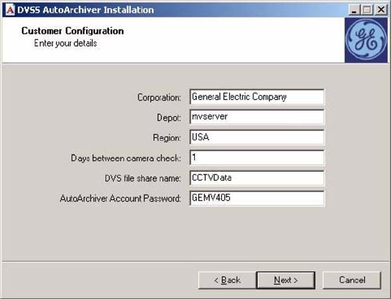
5. Supply Customer Configuration details as shown below and click Next.
6. Supply e-mail addresses to send the specified information to Email
Configuration page, and click Next.
7. Select whether to perform camera check testing.
Camera check testing has specific requirements to work properly and is not
generally applicable to all customers. See “Viewing test images from fleet
DVRs” on page 46 section before selecting this check box.
8. Read the license agreement, click I agree, and then click Next.
9. Unless a special requirement exists, accept the default folder location for
AutoArchiver, and click Next.
10. Unless a special requirement exists, accept the default folder location for
CCTV_Data and click Next.
11. On the Ready to Install page, click Install.
12. Follow additional prompts to complete and finish the installation.
Chapter 2: Installation
8 MobileView Fleet Manager User Manual
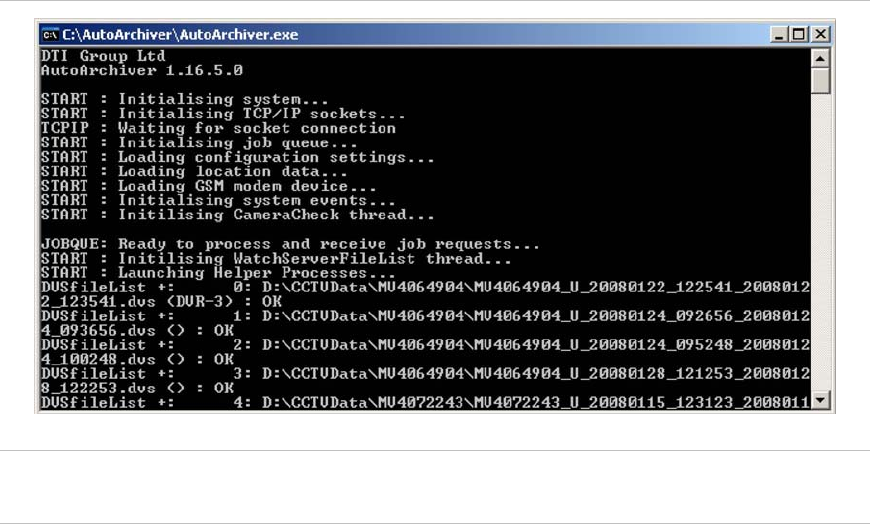
When AutoArchiver installation is complete, double-click the desktop icon to
launch the AutoArchiver application. A console window similar to that shown
in Figure 1 below will open.
Figure 1: AutoArchiver console window
Caution: Do not close this window. Closing the AutoArchiver console window
closes the application. This application must remain open to transfer data.
Installing Fleet Manager
The Fleet Manager software is provided on a CD. This software is installed on a
workstation.
Note: If you have a firewall installed on your computer, configure it to allow this
application.
To install the software:
1. Insert the installation CD into the CD drive.
2. When the launch screen opens, select Fleet Manager from the list of options.
3. On the Welcome page, click Next.
4. Select whether to restore all options to factory default or to uninstall the
previous version.
Both “Restore to factory defaults” and “Uninstall previous version” apply to
systems with a pre-existing or current installation.
Chapter 2: Installation
MobileView Fleet Manager User Manual 9
Restore to factory defaults will restore customized system configurations back
to defaults before the new installation begins. This eliminates incompatible or
archaic configurations settings.
Uninstall previous version will initiate the previous version uninstall routine to
facilitate removal of the previous version. Upon completion of the uninstall
process, the new install will resume.
5. On the Welcome page, click Next.
6. Read the license agreement, click I agree, and then click Next.
7. On the Ready to Install page, click Install.
8. Follow additional prompts to complete and finish the installation.
Chapter 2: Installation
10 MobileView Fleet Manager User Manual
Chapter 3: Using Fleet Manager
12 MobileView Fleet Manager User Manual
Starting AutoArchiver
AutoArchiver is configured to start automatically on system startup. You can also
start the program:
• Via the AutoArchiver icon located on the desktop
— or —
• Navigate to the directory c:\AutoArchiver and execute the application
AutoArchiver.exe
Starting Fleet Manager
Fleet Manager is not configured to start automatically on system startup. You
must start the program:
• Via the Fleet Manager icon located on the desktop
— or —
• Via the Start > Programs > DVSS Fleet Manager menu
Exiting AutoArchiver
Note: Closing the AutoArchiver console window exits the program.
You can exit the AutoArchiver by:
• Clicking inside the console window and pressing the letter “Q” for quit and
exit.
— or —
• Clicking the Close button (the X button in the top-right corner).
Clicking the X button will cause an error. Ignore the error and the console will
close automatically.
Exiting Fleet Manager
Note: Closing the Fleet Management System window exits the program.
You can exit the Fleet Manager by:

Chapter 3: Using Fleet Manager
MobileView Fleet Manager User Manual 13
• Clicking Connection > Exit.
— or —
• Clicking the Close button (the X button in the top-right corner).
Fleet Management System window
The workspace for Fleet Manager is the Fleet Management System window. This
window contains a title bar, menu bar, toolbar, and a status bar. The window is
divided into two panes, a management pane and a maintenance pane. Figure 2
shows the Fleet Management System window and identifies window controls and
panes.
Figure 2: The Fleet Management System window
1
5
6 7
8
3
2
4
4

Chapter 3: Using Fleet Manager
14 MobileView Fleet Manager User Manual
1. Title bar
2. Menu bar
3. Toolbar
4. Tabs
5. Status bar
6. Management pane
7. Maintenance pane
8. Close button
See Table 1 below for additional details.
Table 1: Fleet Management system - window controls
Control Description
Title bar Identifies the Fleet Manager application.
Menu bar Gives access to application commands.
Toolbar Contains buttons for commonly-used application commands. See Table 2
below.
Tabs Display sets of related options.
Status bar Displays application status messages and shows the connection status of
the vehicle, data, jobs, and depot servers.
Management pane Contains vehicle status information on three tabbed pages. See:
“Managing vehicles” on page 28
“How color is used to indicate status” on page 30
““Vehicle shortcut menu” on page 31
“Requesting video footage” on page 34
Maintenance pane Contains the details of vehicles selected in the list, on seven tabbed
pages. See:
“Viewing information about fleet DVRs” on page 39
“Live vehicle GPS data” on page 40
“Data storage on fleet DVRs” on page 42
“Diagnostics” on page 44
“Viewing the DVR interface settings for fleet vehicles” on page 46
“Viewing test images from fleet DVRs” on page 46
“Viewing the status of a DVR during its latest communication” on page 50
Close button Closes the window and exits the application.
Table 2: Fleet Management System - toolbar commands
Button Description
Connect Launches the Connection Manager for connecting to depot servers. See
“Connecting to depot servers” on page 15.
Disconnect Disconnects Fleet Manager from the depot server.

Chapter 3: Using Fleet Manager
MobileView Fleet Manager User Manual 15
Button Description
Vehicles Opens the Vehicle Management tab, which displays status information for fleet
vehicles. See “Managing vehicles” on page 28.
Jobs Opens the Job Request and Transfer Management tab, which displays the
status of requests. See “Vehicle shortcut menu” on page 31.
Files Opens the CCTV and Vehicle Data Management tab, which displays the status
of job requests that are stored in the personal data directory. See “Managing
CCTV and vehicle data files” on page 36.
Refresh Refreshes the display with current information from the depot server.
Viewer Opens the Viewer, which lets you view footage from completed job requests.
See “Viewing requested video footage” on page 37.
Map Shows where each vehicle was located the last time it communicated with the
depot server.
Print (Future) Future Print Option – Option is grayed out.
DVD Burns selected footage onto a DVD.
Delete Deletes the currently selected video archive. You must have sufficient rights to
the file.
Config Launches the Configuration Manager, which lets you change specific settings in
Fleet Manager. See “Configuring the system” below.
Connecting to depot servers
The Connection Manager lets you connect to depot servers.
To connect to a depot server:
1. Click the Connect button.
2. In the Depot Connection dialog box, enter the depot server host name or IP
address, and then click Connect.
Previously connected depot servers will be listed in the drop down list.
Configuring the system
This section describes how to configure your system.
Chapter 3: Using Fleet Manager
16 MobileView Fleet Manager User Manual
Accessing the Configuration Manager
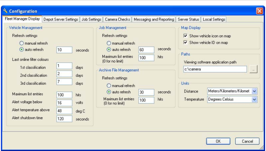
To access the Configuration Manager, click the Config button. The Configuration
dialog box displays as shown in Figure 3 below.
Figure 3: Configuration — Fleet Manager Display tab
Configuring the display of data
The Fleet Manager Display tab of the Configuration Manager gives you control
over the way the system displays data. It lets you configure:
• Vehicle management settings
• Job management settings
• Archive file management settings
• Map display settings
• Paths
• Units

Chapter 3: Using Fleet Manager
MobileView Fleet Manager User Manual 17
Table 3: Fleet Manager Display tab
Option Description
Vehicle Management
Refresh settings Controls how Fleet Manager display is updated with information from depot
servers. Choose one of the following options:
• Manual refresh. The display updates when you click the Refresh button.
• Auto refresh. The display updates automatically at the interval you
specify. The default setting is 60 seconds.
Caution: Since highlighted user selections are deselected during a refresh,
setting the auto refresh time too low can hinder operator interaction.
Last online filter
colors Establishes the duration of three groups that are used to indicate how
recently a specific DVR was online. A specific color is applied to the entries
in each group. (See “How color is used to indicate status” on page 30.) The
three color groups are:
• Dark Green: No setting provided, used to indicate DVR is online
• Light green. The default setting is 1 day.
• Light blue. The default setting is 2 days.
• Pink. The default setting is 4 days.
Note: Color selections are not configurable.
Maximum list
entries Controls the maximum number of entries shown on the Vehicle
Management tab. The default setting is 100. The maximum is 2,000.
Alert voltage below The corresponding “volts” cell on the Vehicle Management tab is highlighted
in pink for online vehicles whose voltage is below the threshold specified
here. Offline vehicles are not highlighted. Vehicles whose threshold is in
tolerance are not highlighted.
Alert temperature
above The corresponding “temp” cell on the Vehicle Management tab is highlighted
in pink for online vehicles whose temperature is above the threshold
specified here. Vehicles whose threshold is in tolerance are not highlighted.
Alert shutdown
time The Shutdown cell on the Vehicle Management tab turns pink for online
vehicles whose shutdown time is above the threshold specified here.
Job Management
Refresh settings Controls how the Jobs Request and Transfer Management display is
updated with information from the depot server. Choose one of the following
options:
• Manual refresh. Information is updated when you click the Refresh
button.
• Auto refresh. The information is updated at the interval you specify here.
The default setting is 60 seconds.
Caution: Since highlighted user selections are deselected during a refresh,
setting the auto refresh time too low can hinder operator interaction.

Chapter 3: Using Fleet Manager
18 MobileView Fleet Manager User Manual
Option Description
Maximum list
entries Controls the maximum number of entries shown on the Job Request and
Transfer Management tab. The default setting is 100. The maximum is
2,000.
Caution: Setting the maximum job count too high can result in excessive
refresh times. Users must adjust the refresh and job count for the specific
installation.
Archive File Management
Refresh settings Controls how the CCTV and Vehicle Data File Management tab is updated
with information from the depot server. Choose one of the following options:
• Manual refresh. Information is refreshed when you click the Refresh
button.
• Auto refresh. The information is refreshed at the interval you specify (in
seconds). The default setting is 30 seconds.
Caution: Since highlighted user selections are deselected during a refresh,
setting the auto refresh time too low can hinder operator interaction.
Maximum list
entries Controls the maximum number of entries shown on the CCTV and Vehicle
Data File Management tab. The default setting is 100. The maximum is
2,000.
Caution: Setting the maximum entries too high can result in excessive
refresh times. Users must adjust the refresh and entries count for the
specific installation.
Map Display
Show vehicle icon
on map Configures Fleet Manager to display vehicle icons on the system map.
Press the Map button to display a map showing each vehicle’s last known
location.
Show vehicle ID on
map Configures Fleet Manager to display the vehicle ID on the system map.
Press the Map button to display a map showing each vehicle’s last known
location.
Paths
Viewing software
application path The directory path of the Video Manager application executable file,
“DVSS_Client.exe”. The default location is C:\Camera.
Units
Distance Displays distance in meters, kilometers, or miles.
Temperature Displays temperature in degrees Celsius or degrees Fahrenheit.
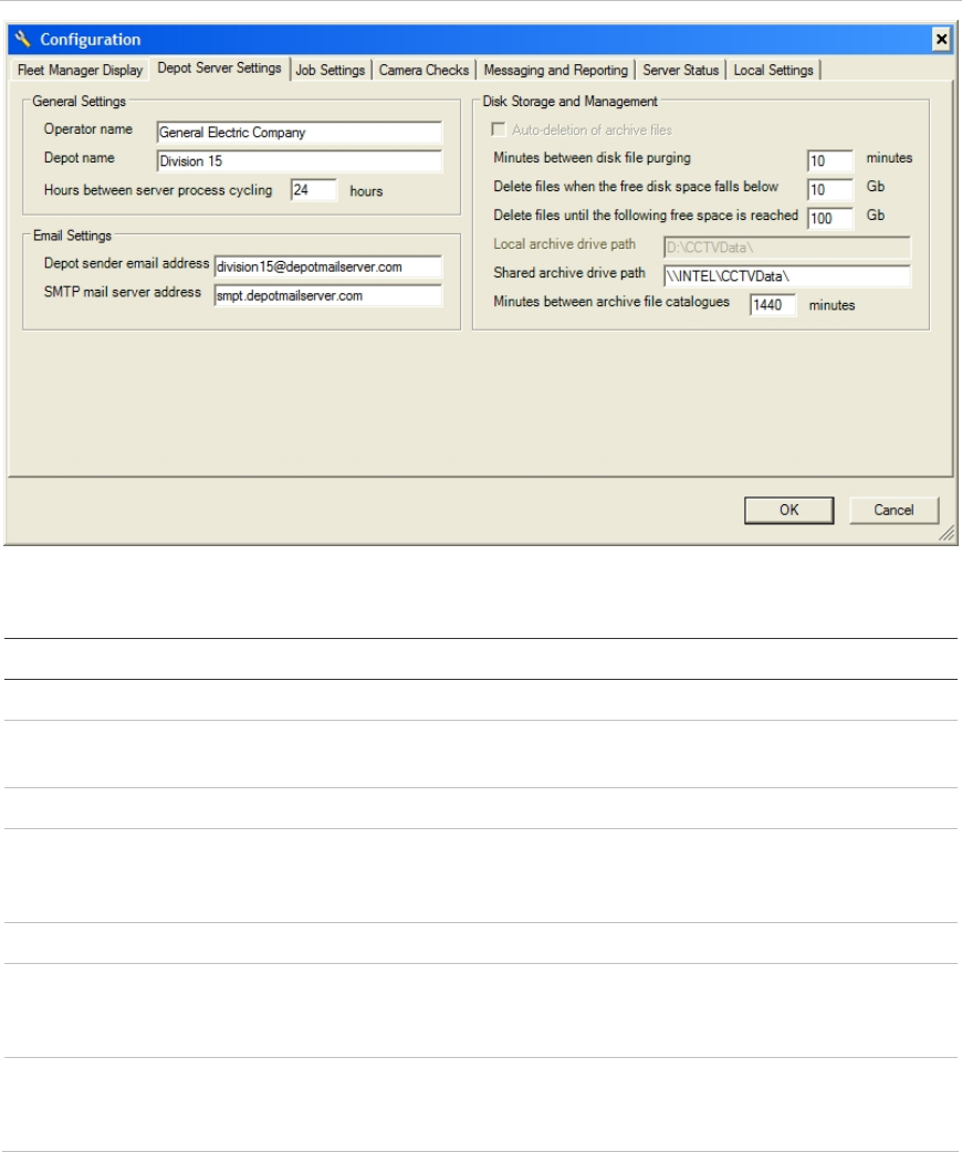
Configuring the depot server
The Depot Server Settings tab lets you configure:
• General settings
Chapter 3: Using Fleet Manager
MobileView Fleet Manager User Manual 19
• E-mail settings
• Disk storage and management
These settings are specific to the depot server. They have no configuration
affect on the Fleet Manager application running on the local machine.
Figure 4: Depot Server Settings tab
Table 4: Depot Server Settings tab
Option Description
General Settings
Operator name This entry identifies the corporation operating the depot server. This is
specified during AutoArchiver installation but can be changed here.
Depot name Identifies the depot the specific installation of AutoArchiver services.
Hours between server
process cycling Controls the frequency of server process cycling. The default setting is
24 hours. This is a watchdog control facility and the server automatically
restarts according to the duration of this setting.
E-mail Settings
Depot sender e-mail
address Contains the address or distribution list where depot email messages
are sent. This is specified during AutoArchiver installation but can be
changed here.
SMTP mail server
address Contains the SMTP mail server. This is specified during AutoArchiver
installation but can be changed here. Set this value to N during
installation if you don’t have this information at hand.

Chapter 3: Using Fleet Manager
20 MobileView Fleet Manager User Manual
Option Description
Disk Storage and Management
Minutes between disk
file purging Sets the number of minutes to wait after completion of the previous
purge process before beginning the subsequent purge process. This
affects files with DVS extensions stored in the CAMDATA share
specified in this same tab section. The default setting is 10 minutes.
Delete files when the
free disk space falls
below
Sets the minimum amount of free space on the physical HDD containing
the CAMDDATA share before automatic file deletion initiates. The
default setting is 0 GB.
Delete files until the
following free space is
reached
Sets the amount of remaining space at which file deletion stops. The
default setting is 200 GB.
Local archive drive
path Defines the path to the AutoArchiver data folder on the AutoArchiver
computer. This parameter is set during AutoArchiver application install
and cannot be changed. The default location is D:\CCTVData.
Shared archive drive
path Defines the Windows network share name of the AutoArchiver data
folder specified above. The default name is \\ServerName\CCTVData.
ServerName refers to the machine name of the AutoArchiver server.
Minutes between
archive catalogs Defines the number of minutes that must elapse before re-indexing the
video file list from the shared location. The default of 1440 minutes
equals 24 hours or 1 day.
Note: New user jobs (CCTV Request) will appear in the CCTV and
Vehicle Data File Management tab at the next refresh. Auto Download
Vehicle Event and Alarm type jobs will not appear until the next archive
catalog index.
Chapter 3: Using Fleet Manager
MobileView Fleet Manager User Manual 21
File Purge Operation
Every X minutes, as set by the “Minutes between disk file purge”, files with the
DVS extension are purged from the CCTVData share if the CCTVData free
space drops below the “Delete files when the free disk space fall below”
parameter. File deletion will continue until such time as the disk free space rises
above the “Delete files unitl the follow free space is reached” parameter. File
deletion starts with the oldest DVS files and continues to the newest until free
space exceeds the value specified by the "Delete files until the follow free space
is reached" parameter.
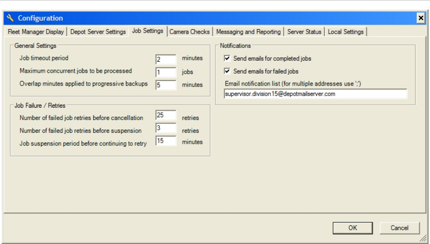
Configuring job settings
In the Fleet Management System window, a job is a request for video footage or
event data. The Job Settings tab lets you set parameters for downloading data
files. This includes:
• General settings
• Job failures and retries
• E-mail notifications
Figure 5: Job Settings tab

Chapter 3: Using Fleet Manager
22 MobileView Fleet Manager User Manual
Table 5: Job Settings tab
Option Description
General Settings
Job timeout period Sets the duration (in minutes) of inactivity in jobs, caused by a
broken connection between the DVR and the AutoArchiver, at
which the system requeues the job. The “Failed attempts” cell
increments each time a job is requeued. The default setting is 2
minutes.
Maximum concurrent jobs to be
processed Sets the number of simultaneous downloads the AutoArchiver
will process. The default setting is 1 job. The maximum value is
5 jobs.
Note: Setting this variable to high can impact system
performance. Generally 3 simultaneous jobs is the maximum
practical limit.
Job Failure/Retries
Number of failed job retries
before cancellation Specifies the number of times you want the system to retry
when a job fails before canceling the job. The default setting is
25 retries.
Number of failed job retries
before suspension Specifies the number of times you want the system to retry
when a job fails before suspending the job for a period of time.
This allows time for the vehicle to move to a new location where
service is available. The default setting is 3 retries.
Job suspension period before
continuing to retry Specifies how long (in minutes) the system suspends a job
before initiating the next round of retries. The default setting is
15 minutes.
Notifications
Send e-mails for completed
jobs The default setting is Enabled.
Send e-mails for failed jobs The default setting is Enabled.
E-mail notification list List of e-mail address recipients.
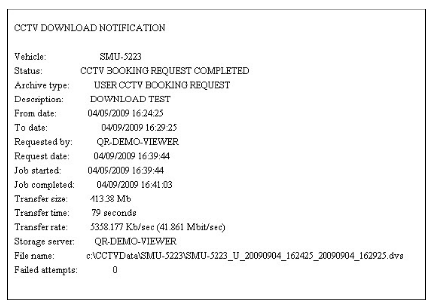
E-mail notifications
If enabled, Fleet Manager can send e-mail notifications for completed or failed
jobs. Simply enter emails addresses into the supplied box separated by a
semicolon “;”. Figure 6 on page 23 shows a sample of an e-mail notification.
Table 5 above describes the options available in configuring notifications.
Chapter 3: Using Fleet Manager
MobileView Fleet Manager User Manual 23
Figure 6: E-mail notification sample
Chapter 3: Using Fleet Manager
24 MobileView Fleet Manager User Manual
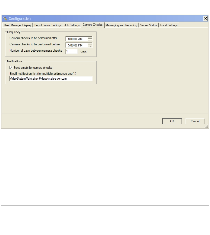
Configuring camera testing
Fleet Manager can automatically download sample images from cameras
attached to MobileView systems. This reduces camera testing and validation
time. This feature is configured in the Camera Checks tab.
Figure 7: Camera Checks tab
Caution: For best image results, camera check times should be set for daylight
hours. Camera check hours must progress from an earlier time to a later time.
Table 6: Camera Checks tab
Option Description
Frequency
Camera checks to be performed after Specifies the time after which testing can be
performed. The default setting is 8:00:00 a.m.
Camera checks to be performed before Specifies the time after which testing stops. The
default setting is 5:00:00 p.m.
Number of days between camera checks Specifies the number of days between camera tests.
The default setting is 1 day.
Chapter 3: Using Fleet Manager
MobileView Fleet Manager User Manual 25
Option Description
Notifications
Send e-mails for camera checks Notifies the e-mail recipient of the camera check
activity.
E-mail notification list List of e-mail address recipients.
Note:
Camera checks occur between the specified times only while the MobileView is
online to the AutoArchiver. Camera checks will not occur if the vehicle is offline
during the specified times.
The email feature requires the AutoArchiver computer connect to a SMTP mail
server. This configuration is explained in Table 4 on page 19.
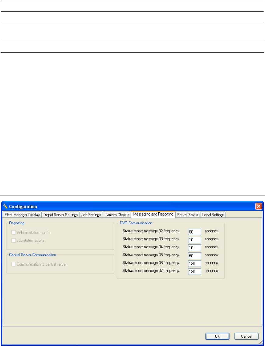
Configuring messages and reporting
The Reporting and Central Server Communication settings shown on the
Messaging and Reporting tab are read-only. If you need to change the settings,
contact technical support. (See “Contacting us” on page 54.)
Figure 8: Messaging and Reporting tab
The variables under DVR communication control how often AutoArchiver polls
the DVR fleet for specific information. Information is broken into different
message types. Table 7 on page 26 provides a description for each message
type.

Chapter 3: Using Fleet Manager
26 MobileView Fleet Manager User Manual
Note: Each frequency variable has been set to yield the best performance in a
broad range of environments. Changing these values may degrade system
performance. Refer to Table 8 below for recommended default values.
Table 7: Status report message description
Number Description
32 System voltages and temperatures
33 Analog/digital input/output status
34 DVR GPS location
35 Data storage status
36 General status (software version, serial ID, IP addresses, etc.)
37 Cumulative status report including average/minimum/maximum
temperatures, shutdown reasons, and image/sound/GPS records recorded
Table 8: Messaging and Reporting tab default values
Option Description
Status report message 32 frequency The default setting is 60 seconds
Status report message 33 frequency The default setting is 10 seconds
Status report message 34 frequency The default setting is 10 seconds
Status report message 35 frequency The default setting is 60 seconds
Status report message 36 frequency The default setting is 120 seconds
Status report message 37 frequency The default setting is 120 seconds
Viewing server status data
The Server Status tab displays generic depot server settings. These values are
read-only.
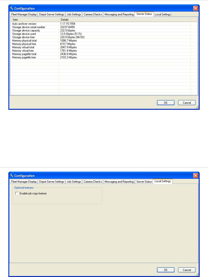
Chapter 3: Using Fleet Manager
MobileView Fleet Manager User Manual 27
Figure 9: Server Status tab
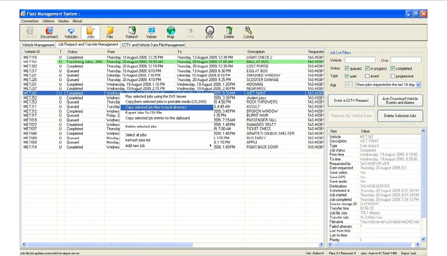
Configuring local settings
The Local Settings tab gives you the option to copy completed jobs to your local
PC or laptop directory.
Figure 10: Local Settings tab
To enable job copy feature, check the “Enable job copy feature” check box.
To disable job copy feature, clear the “Enable job copy feature” check box.
Chapter 3: Using Fleet Manager
28 MobileView Fleet Manager User Manual
Figure 11: Job Copy Feature
To access this feature once enabled, right-click on the selected job, and then
click “Copy selected job files to local directory”, as shown in Figure 11 above.
Working with Fleet Manager
This section provides information about the Fleet Manager workspace and gives
instructions for performing common tasks.
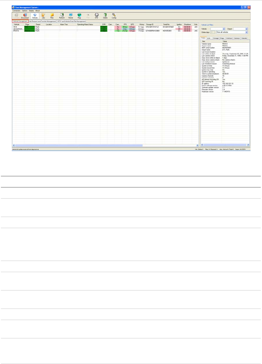
Managing vehicles
You can view the status of vehicles in your fleet, request event data or video, set
up camera testing, and perform other tasks on the Vehicle Management tab
(shown in Figure 12 on page 29).
Chapter 3: Using Fleet Manager
MobileView Fleet Manager User Manual 29
Figure 12: Vehicle Management tab
Table 9: Items displayed on the Vehicle Management tab
Item Description
Vehicle Displays the vehicle ID number.
Rego Displays the vehicle registration or license plate number. (Frequently the
same as the vehicle number described above.)
Depot Identifies the depot (or garage) server to which the recorder is assigned.
Location Indicates the vehicle’s location within the depot. Available for DVRs with
GPS units in garages where the parking sections are mapped. Maps are
stored in the C:\Camera\Maps directory and only show the location of the
DVR while in the depot.
Alarm Time Displays the last time an alarm was triggered.
Operating/Alarm
Status Displays the operating or alarm status of the DVR unit.
DVR Indicates the number of days since the DVR’s last contact with the depot
server.
Cam Check Indicates the number of days since the last camera check.
FPS Indicates the average, overall frames per second recorded by the DVR
during the last reporting period.
GPS Indicates the average of positions per minute recorded during the last
reporting period. Positions per minute refers to the latitude and longitude
coordinate updates provided to the GPS module.
History Indicates number of days of video footage currently stored on the DVR.

Chapter 3: Using Fleet Manager
30 MobileView Fleet Manager User Manual
Item Description
Storage ID Contains the serial number of the DVR’s hard drive.
Serial No Contains the serial number of the DVR.
Ignition Indicates the on/off state of the vehicle ignition.
Shutdown Indicates the length of time before the unit shuts down. This countdown
timer activates when the vehicle ignition shuts off. If it’s set to 00:00:00, the
DVR is either already OFF or the ignition is still ON.
Volts Indicates the minimum voltage recorded by the DVR during the past
recording period.
Vavg Indicates the average voltage recorded by the DVR during the past
recording period.
Temp Indicates the maximum temperature during the past recording period.
Tavg Indicates the average temperature during the past recording period.
SW Vers Indicates the software version running on the DVR.
Model Contains the model number of the DVR.
Map Indicates whether or not the DVR has position data and is displayed on the
map.
How color is used to indicate status
Colored highlights are applied to cells in the Fleet Management System window
to show how recently each DVR was online. Table 10 below shows how the
highlighting is applied.
Table 10: Colored highlighting in the Fleet Management System window
Color Most recent communication with DVR [1]
Dark green Currently online
Light green 1 day ago
Light blue 2 to 4 days ago
Pink 4 or more days ago
[1] Except for dark green, the number of days in each color group can be changed. The color
selection is not configurable. See “Last online filter colors” in Table 3 on page 17.
Chapter 3: Using Fleet Manager
MobileView Fleet Manager User Manual 31
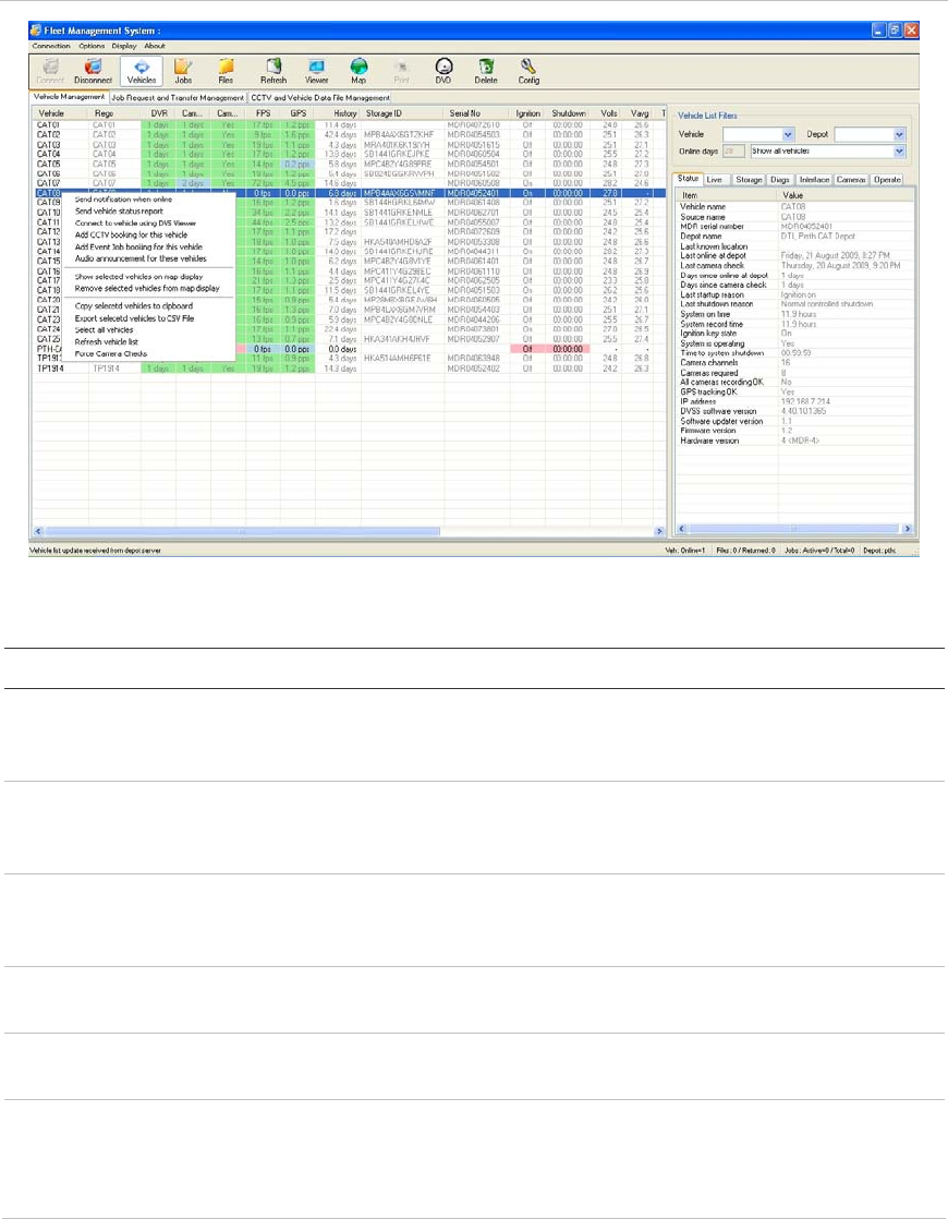
Vehicle shortcut menu
Additional Vehicle Management commands are available on a shortcut menu. To
open the shortcut menu, right-click any vehicle.
Figure 13: Vehicle shortcut menu
Table 11: Vehicle shortcut menu commands
Command Description
Send notification when online When the vehicle returns to the garage and connects to the
depot server, an e-mail is automatically sent to the specified e-
mail address.
Send vehicle status report Sends a vehicle status report to the specified e-mail address.
The report includes the most recent image of each camera
stored on the server for the selected vehicle.
Connect to vehicle using DVS
Viewer Automatically launches Video Manager and connects to the
selected vehicle to show live video data if the vehicle is at the
garage and online.
Add CCTV booking to this
vehicle Opens the CCTV booking window for the selected vehicle.
Add event job booking to this
vehicle Opens the event job booking window for the selected vehicle.
Show selected vehicle on map
display Opens the map display window and shows the selected vehicle
on the map. This requires map data for the respective area. All
vehicles that have previously reported in with position data can
be shown on the map display.

Chapter 3: Using Fleet Manager
32 MobileView Fleet Manager User Manual
Command Description
Remove selected vehicle from
map display Removes the selected vehicle from the map display window.
Copy selected vehicles to
clipboard Copies vehicle data for the selected vehicles to the Windows
clipboard.
Export selected vehicles to csv
file Exports data for the selected vehicle to a file in csv format. The
csv format can then be opened by Microsoft Excel for analysis.
Refresh vehicle list Updates the vehicle list with the most current information.
Force camera checks Forces a camera check on the selected vehicle. This function is
useful during the commissioning of a bus to obtain an image of
each camera for commissioning purposes.
Working with job requests and transfers
The Job Request and Transfer Management tab, shown below, displays the
status of existing video and data requests. In addition to checking the status of
existing requests, you can use the maintenance pane tab to:
• Request video footage
• Set up automatic download of vehicle event and alarm data
• Retrieve all vehicle data
Figure 14: Job Request and Transfer Management tab

Chapter 3: Using Fleet Manager
MobileView Fleet Manager User Manual 33
Job request and transfer data is provided in both the management and
maintenance panes. Since information in the maintenance pane is more
complete, Table 12 below provides a description of each information item.
Table 12: Job Request and Transfer Management tab
Item Description
Vehicle ID Contains the vehicle ID number.
Description Contains the archive description entered by the system operator when the
download job was entered.
Type Indicates the type of job request:
• (U) user request = CCTV request
• (A) auto/ event request = Autodownload vehicle events and alarms
• (P) progressive request = Retrieve all Vehicle data
Job status Indicates the status of the requested jobs. There are three statuses:
• Queued = waiting for connection
• In progress = transferring data
• Completed = the job is done
• Failed = job request failed
From time The start date & time of the selected surveillance archive.
To time The end date & time of the selected surveillance archive.
Requested by Identifies the server or computer which requested the footage.
Date requested Date and time the surveillance archive request was entered.
Save video Indicates whether the surveillance archive contains video data. Shown as V
in the management pane.
Save GPS Indicates whether the surveillance archive contains GPS data. Shown as G
in the management pane.
Save audio Indicates whether the surveillance archive contains audio data. Shown as A
in the management pane.
Destination Identifies the depot server to which data will be downloaded.
Scheduled at Indicates when the download is scheduled to take place.
Job started Indicates when the job started.
Job completed Indicates when the job was completed.
Source Storage ID Serial number of the media from which the surveillance archive was
downloaded.
Transfer time Indicates the amount of time required to transfer the requested data from
the vehicle to the server.
Job file size Indicates the size (in bytes) of the job output file.
Transfer rate Indicates the rate (in bytes/sec.) at which the data was transferred.
Filename Identifies the surveillance archive filename and location as stored on depot
server.

Chapter 3: Using Fleet Manager
34 MobileView Fleet Manager User Manual
Item Description
Failed attempts Indicates how many failed attempts occurred during download.
Priority Indicates the priority assigned to the request.
Requesting video footage
You can request video footage from a local or remote vehicle. The footage will be
downloaded as soon as the vehicle returns to the depot and comes within range
of the wireless network.
To request video footage:
1. Click “Enter a CCTV Request.” The User Data Request Form opens.
2. Enter the required information. See Table 13 below for information about the
values required.
3. Click Add job.
Table 13: User Data Request Form details
Setting Information required
Vehicle ID This field is automatically populated with the vehicle ID from the
select drop down box..
Select Allows selection of the vehicle ID from a drop down box or direct
entry into the select box. You can type the vehicle ID manually or
select it from the list of available vehicles in the drop down box.
Description Type a description of the footage for future reference.
From Time
and To Time Enter the beginning and ending times of the video segment being
requested. To do this, click the arrow to open the calendar, and then
select the date.
User name and password Provide a user name and password for the system identified next to
the “Enter details for:” entry. Credentials for the AutoArchiver
computer are required if if the checkbox “Autoarchiver
Authentication” is selected. Otherwise, enter credentials for the
DVR.
Save data Select checkboxes next to “Save Video”, “Save Audio”, or “Save
GPS” to save the identified data types. Clear the selection for
undesired data types.
Schedule at Click the up or down arrows to schedule a date and time for the
download.
Destination This the name of the destination server. It is not user configurable.

Chapter 3: Using Fleet Manager
MobileView Fleet Manager User Manual 35
Setting Information required
Priority Select the download priority from the dropdown list. Setting
download priority affects how the DVR reacts during the save
process. Low has no effect. Medium temporarily reduces the DVR
frame rate by half its normal setting. High reduces the DVR frame
rate to 1 frame per second. (This setting works with MobileView 4
only.)
Channel filter Enter channels from which to download data. For example, enter “1,
2” to download surveillance data from channels 1 and 2 only..
Frame filter Enter the maximum frame rate of the saved surveillance file. This
setting reduces the frame rate of each saved camera to the
specified quantity in the saved file only. The setting does not
change the frame rate on the DVR.
E-mail notification list Enter the e-mail addresses of persons to be notified when the job is
complete. Click the drop down to select a previously entered e-mail
address from a list. Use a semicolon (;) to separate multiple e-mail
addresses.
Requesting automatic download of event data and video
Fleet Manager allows automatic download and update of several data types.
These are listed below.
• Log files
• Camera checks
• Health & Status
• Video footage placed in the vehicle’s archive space
Download of all the above items are automatically enabled when the Auto
Download Vehicles Event and Alarms form is completed. (See Table 14 on page
36.)
Note: Recorder status and health information will not be shown unless an auto
download event is configured for the recorder.
To configure automatic downloading:
1. Click Auto Download Vehicle Events and Alarms. The Event Archive Auto-
Download Request Form opens.
2. Enter the required information. See Table 14 on page 36 for information about
the values required.
3. Click Add job.

Chapter 3: Using Fleet Manager
36 MobileView Fleet Manager User Manual
Table 14: Event Archive Auto-Download Request Form details
Setting Information required
Vehicle ID This field is automatically populated with the vehicle ID from the
select drop down box.
Available Allows selection of the vehicle ID from a drop down box or direct
entry into the select box. You can type the vehicle ID manually or
select it from the list of available vehicles in the drop down box.
Description Enter a description of the footage for future reference.
Leave archive on
vehicle Select this checkbox to leave the archive on the vehicle after it has
been automatically downloaded. This box is normally deselected.
User name and
password Provide a user name and password for the system identified next to
the “Enter details for:” entry. Credentials for the AutoArchiver
computer are required if if the checkbox “Autoarchiver
Authentication” is selected. Otherwise, enter credentials for the
DVR.
Destination Enter the destination for the download.
E-mail notification list Enter the e-mail addresses of anyone you want notified. Separate
each address with a semicolon (;).
Note: Recorder status and health information will not be shown unless an auto
download event is configured for the recorder.
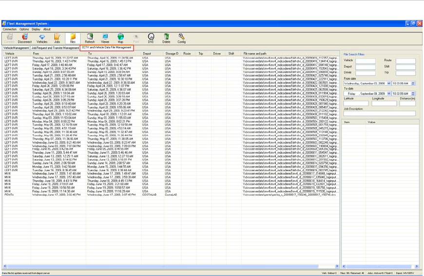
Managing CCTV and vehicle data files
The CCTV and Vehicle Data Management tab displays the status of CCTV
download requests.
Chapter 3: Using Fleet Manager
MobileView Fleet Manager User Manual 37
Figure 15: CCTV and Vehicle Data Management tab
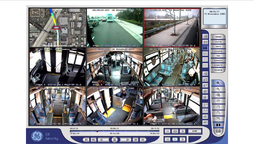
Viewing requested video footage
When a requested video is received, the status of the request changes to
Completed. Fleet Manager displays the time range and a description of the
requested video segment, along with the user who entered the request (for user
requests only — this information is not given for automatic downloads).
To view requested video:
1. Select the completed request from the management pane (with the CCTV
and Vehicle Data Management tab selected).
2. Click the Viewer toolbar button to automatically open Video Manager and
begin playback of the selected surveillance file.
Chapter 3: Using Fleet Manager
38 MobileView Fleet Manager User Manual
Figure 16: Fleet Manager Viewer
Notes:
• If Video Manager is already open, it must be closed before clicking the Viewer
button.
• If Fleet Manger is being run on the depot server, Video Manager will not
launch.
• CCTV requests transfer a large amount of data. Network bandwidth
limitations may affect the playback performance. If this occurs, use the “Copy
selected job entries to local directory” feature to make a local copy of the file
for playback.
Fleet maintenance
The Maintenance pane occupies the right side of the Fleet Management System
window. When you select the Vehicle Management tab, the maintenance pane
shows the details about the selected vehicles on a series of seven tabs. These
are:
• Status
• Live
• Storage
• Diagnostics
Chapter 3: Using Fleet Manager
MobileView Fleet Manager User Manual 39
• Interface
• Cameras
• Operate
Details about each tab are given below.
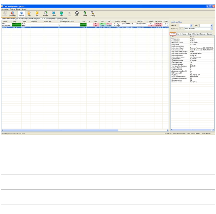
Viewing information about fleet DVRs
The Status tab in the maintenance pane displays operational and maintenance
information about fleet DVRs.
Figure 17: Status tab
Table 15: Status tab — information on DVRs
Item Description
Vehicle name Contains the vehicle ID number.
Source name Contains the registration or license plate number of the vehicle
which may be the same as the vehicle number.
MDR serial number Contains the serial number of the recorder. MDR is a generic
mnemonic meaning Mobile Data Recorder.
Depot name Identifies the depot (or garage) that has been selected.

Chapter 3: Using Fleet Manager
40 MobileView Fleet Manager User Manual
Item Description
Last known location Indicates the vehicle’s location within the garage. (Available for
DVRs with GPS units in garages where the parking sections are
mapped.)
Last online at depot Contains the date of the DVR’s last contact the depot server.
Last camera check Contains the date of the DVR’s last camera check.
Days since online at depot Indicates the number of days since the DVR’s last contact with the
depot server.
Days since camera check Indicates the number of days since the last camera check.
Last startup reason Indicates the circumstance of the DVR’s most recent startup.
Last shutdown reason Indicates the circumstance of the DVR’s most recent shutdown.
System on time Indicates number of hours that the DVR was on before connecting
to the depot server.
System record time Indicates number of hours recorded before the DVR was connected
to the depot server.
Ignition key state Indicates the last known on/off state of the vehicle ignition key.
System is operating Indicates the system operating state during its last communication
with the depot server.
Time to system shutdown Indicates the length of time after ignition shutoff until the DVR turns
off.
Camera channels Contains the number of camera channels on the DVR.
Cameras required Contains the number of cameras configured for the DVR.
All cameras recording OK Indicates the current status of the cameras connected to the DVR.
GPS tracking OK Indicates the current status of the GPS.
IP address Contains the IP address of the DVR.
DVSS software version Contains the software version of the DVR application.
Software updater version Contains the version of the DVR software updater.
Firmware version Contains the DVR firmware version.
Hardware version Contains the DVR hardware version.
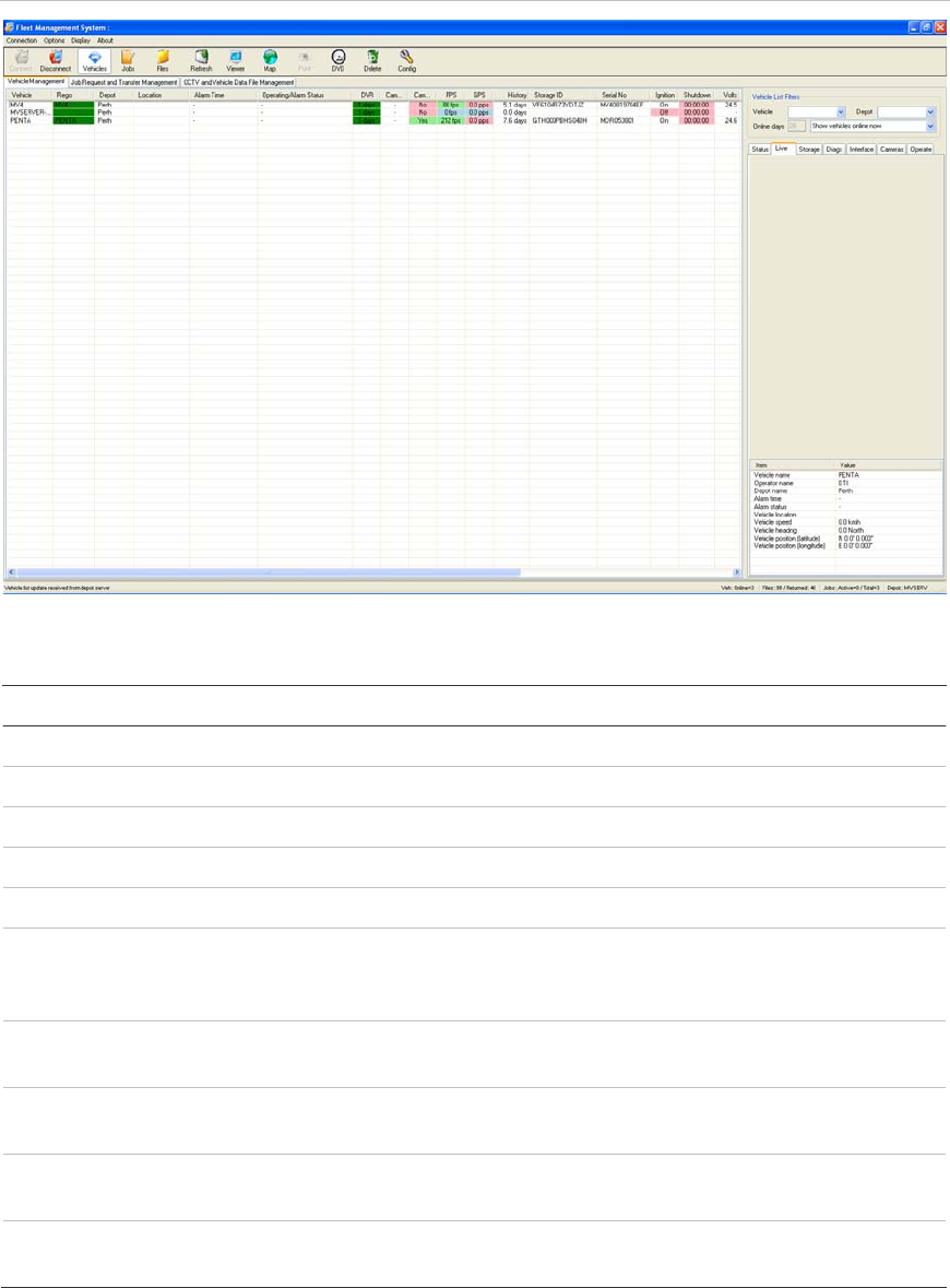
Live vehicle GPS data
For DVRs with GPS installed and enabled, the Live tab gives information useful
for locating a vehicle, such as the vehicle’s location, speed, and direction of
travel during its most recent communication with the depot server.
Chapter 3: Using Fleet Manager
MobileView Fleet Manager User Manual 41
Figure 18: Live tab
Table 16: Live tab — vehicle GPS data
Item Description
Vehicle name Contains the vehicle number.
Operator name Contains the corporation name registered in the AutoArchiver.
Depot name Identifies the depot server.
Alarm time Contains the date of the last alarm activation.
Alarm status Indicates whether or not the alarm is activated.
Vehicle location Indicates the vehicle’s location within the garage. (Available for
DVRs with GPS units in garages where the parking sections are
mapped.)
Vehicle speed Contains the speed at which the vehicle was traveling during its
last communication with the depot server.
Vehicle heading Contains the vehicle’s direction of travel during its last
communication with the depot server.
Vehicle position (latitude) Contains the vehicle’s latitude during its last communication with
the depot server.
Vehicle position (longitude) Contains the vehicle’s longitude during its last communication with
the depot server.
Chapter 3: Using Fleet Manager
42 MobileView Fleet Manager User Manual
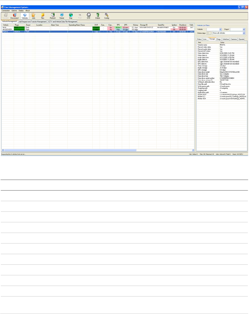
Data storage on fleet DVRs
The Storage tab displays information about data storage on the fleet DVRs.
Figure 19: Storage tab
Table 17: Storage tab — data storage on DVRs
Item Description
Vehicle name Contains the vehicle number.
Record video data Indicates whether video is being recorded.
Record audio data Indicates whether audio is being recorded.
Record GPS data Indicates whether GPS is being recorded.
Video data from Contains the earliest date of the video data.
Video data to Contains the latest date of the video data.
Audio data from Contains the earliest data of the audio data.
Audio data to Contains the latest date of the audio data.
GPS data from Contains the earliest date of the GPS data.
GPS data to Contains the latest date of the GPS data.
Video storage Indicates the number of days of video storage currently stored on
the DVR.

Chapter 3: Using Fleet Manager
MobileView Fleet Manager User Manual 43
Item Description
Audio storage Indicates the number of days of audio storage currently stored on
the DVR.
GPS storage Indicates the number of days of GPS storage currently stored on
the DVR.
Data drive model Contains the model of the DVR’s hard drive.
Data drive size Contains the size of the DVR’s hard drive.
Data drive free Contains the amount of free space on the DVR’s hard drive.
Data drive serial number Contains the serial number of the DVR’s hard drive.
Data drive volume ID Contains the volume ID of the hard drive.
Writing to alternate drive Indicates whether the DVR is storing data on an alternate drive.
Data file path Contains the file path to the DVR’s data file.
Workspace path Contains the workspace path within the DVR.
Outgoing path Contains the path for outgoing data within the DVR.
Logging path Contains the path to where log files are stored within the DVR.
Application path Contains the path to where the application within the DVR is
located.
INI file MDR Contains the path to where the MDR INI file is located within the
DVR.
INI file FLT Contains the path to where the FLT INI file is located within the
DVR.
INI file VEH Contains the path to where the VEH INI file is located within the
DVR.
Chapter 3: Using Fleet Manager
44 MobileView Fleet Manager User Manual
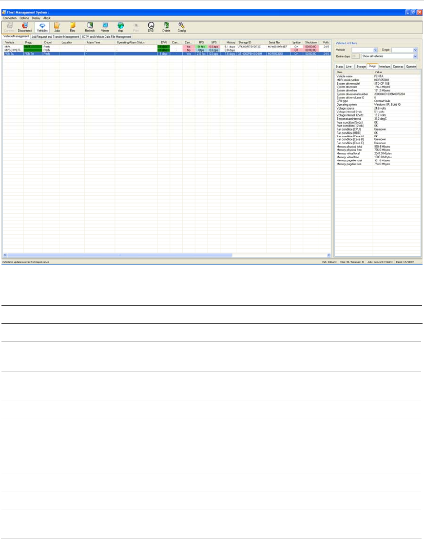
Diagnostics
The Diagnostics (Diags) tab displays alarm status and vehicle speed, direction,
and location.
Figure 20: Diagnostics tab
Table 18: Diagnostics tab — alarm status and vehicle speed, direction, and location
Item Description
Vehicle name Contains the vehicle ID number.
MDR serial number Contains the serial number of the MDR/DVR. MDR is the low-
level name for the DVR Mobile Data Recorder.
System drive model Identifies the model of the drive on the depot server that contains
the operating system and applications .
System drive size Contains the size of the DVR’s drive.
System drive free Indicates the amount of free space remaining on the drive.
System drive serial number Contains the drive’s serial number.
System drive volume ID Contains the drive’s volume ID.
CPU type Contains the DVR’s CPU type.
Operating system Contains the DVR’s operating system type and build.
Voltage source Contains the DVR’s input voltage during the last communication
with the depot server.

Chapter 3: Using Fleet Manager
MobileView Fleet Manager User Manual 45
Item Description
Voltage internal 5 VDC Contains the voltage of the internal 5 V power supply during the
DVR’s last communication with the depot server
Voltage internal 12 VDC Contains the voltage of the internal 12 V power supply during the
DVR’s last communication with the depot server.
Temperature internal Contains the DVR’s internal temperature during the last
communication with the depot server.
Fuse condition (5vdc) Contains the condition of the DVR’s 5 V power out fuse.
Fuse condition (12vdc) Contains the condition of the DVR’s 12 V power out fuse.
Fan condition (CPU) Contains the condition of the DVR’s CPU fan.
Fan condition (HDD) Contains the condition of the DVR’s HDD fan.
Fan condition (Case A) Contains the condition of the DVR’s case A fan. This applies only
to MobileView PENTA.
Fan condition (Case B) Contains the condition of the DVR’s case B fan. This applies only
to MobileView 4.
Fan condition (Case C) Contains the condition of the DVR’s case C fan. This applies only
to MobileView 4.
Memory physical total Contains the DVR’s total physical memory.
Memory physical free Contains the DVR’s free memory.
Memory virtual total Contains the DVR’s total virtual memory.
Memory virtual free Contains the DVR’s free virtual memory.
Memory pagefile total Contains the DVR’s total memory page file size.
Memory pagefile free Contains the DVR’s free memory page file size.
Chapter 3: Using Fleet Manager
46 MobileView Fleet Manager User Manual
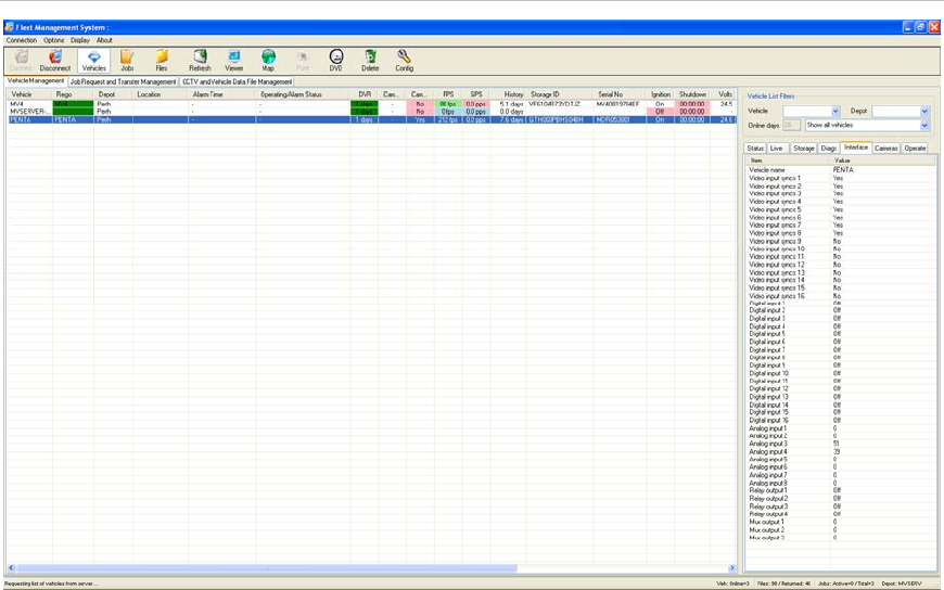
Viewing the DVR interface settings for fleet vehicles
The Interface tab displays the interface settings applied to the selected DVR
during its last communication with the depot server. This tab lets you view the
settings of the DVR’s video, analog, digital, and multiplexer inputs.
Figure 21: Interface tab
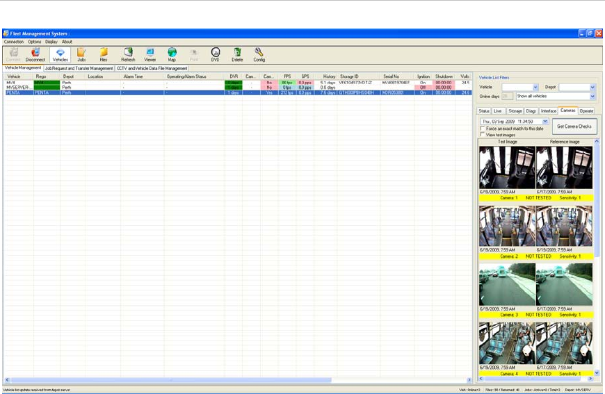
Viewing test images from fleet DVRs
The cameras tab provides a side-by-side comparison of recent camera images
from the selected DVR against previously established reference images. This
time saving feature provides a centralized means of checking whether a camera
image has changed to an unacceptable degree.
Camera image updates, called test images, can be obtained up to a maximum of
once per day when the DVR is online to the depot server. If an image has
changed, historic query of past test images helps identify when the change
occurred. This can aid with investigations if the change was vandal related.
Chapter 3: Using Fleet Manager
MobileView Fleet Manager User Manual 47
Figure 22: Cameras tab
Fleet Manager provides a means of updating a camera’s reference image if the
camera has been replaced or its field of view changed.
Update a reference image:
1. Select the DVR to be checked.
2. Select the cameras tab in the maintenance pane
3. Select the date containing the desired reference image.
4. Click “Get camera checks”.
The current reference and test image for the selected date will display.
If the selected date does not have a test image, the latest available image
before the selected date will be displayed.
If the selected date does not have a test image and “Force an exact match to
this date” is checked, an error will display indicating no information is
available on the specified date.
5. Double-click any image to expand it.
6. Clicking the “Set as Reference” box will update the current image to be the
reference image.

Chapter 3: Using Fleet Manager
48 MobileView Fleet Manager User Manual
If camera check testing was selected during AutoArchiver installation, the user
may check test results of a test from a particular date.
To check a camera for alignment, focus, and graffiti:
1. Select the DVR to be checked.
2. Select the cameras tab in the maintenance pane
3. Select the date containing the desired reference image.
4. Check the “View test images” box
5. Click “Get camera checks”.
The current reference and test image for the selected date will display.
If the selected date does not have a test image, the latest available image
before the selected date will be displayed.
If the selected date does not have a test image and “Force an exact match to
this date” is checked, an error will display indicating no information is
available on the specified date.
6. Double-click any image to expand it.
7. Use the scroll bar to check test results from each camera configured on the
vehicle. Results are color coded per Table 20 below.
Notes
• Camera test checks occur with the same frequency as camera checks and
the features are interdependent.
• Camera test checks are available only if the vehicle was within range of the
wireless network during the hours specified in the configuration.
• For information on configuring camera check frequency and times, see
“Configuring camera testing” on page 24.
If the “View test images” box is checked, the image columns may display “ghost”
images. This is due to the algorigthm averaging the images and is normal.
Table 19: Camera check status color description
Color Description
Green Camera check was successful.
Red Camera check was unsuccessful. This indicates the image
comparison made by the algorithm did not match. This does
not necessarily mean that the camera is not working. The
camera test only determines if there are major differences
between the two images.
Chapter 3: Using Fleet Manager
MobileView Fleet Manager User Manual 49
Ghost images
On a daily basis, the DVR generates multiple test images for each camera on a
vehicle. These are sent to the AutoArchiver for camera checks. Before the
AutoArchiver executes the camera check test algorithm, it gathers all the images
for a vehicle on a given day and averages them into one image. The blended
image may have ghost images. This averaged image removes unwanted artifacts
that can cause false positives. The AutoArchiver generates the averaged image
after all the individual images for the current day have been received.
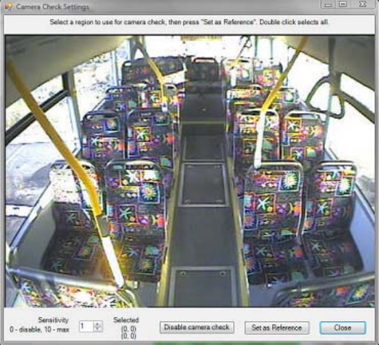
Modifying a reference image or hotspot
Fleet Manager allows user to define the specific image area the camera check
test function compares. This fine tuning helps eliminate section of the image that
are known to change. Examples are windows and seats.
To modify an existing reference image or set a hotspot:
1. After conducting a camera check and setting a reference image, double-click
the image that will have a comparison area defined. A Camera Check
Settings dialog box displays as shown in the figure below.
2. Modify the comparison sensitivity level. Experimentation is required to find an
optimum setting. The range is 1 (lowest) to 10 (highest). Starting with a
sensitivity level of 1 (default) is recommended.
3. Place the mouse within the image and define a reference region. The region
will be the area checked by the comparison algorithm.
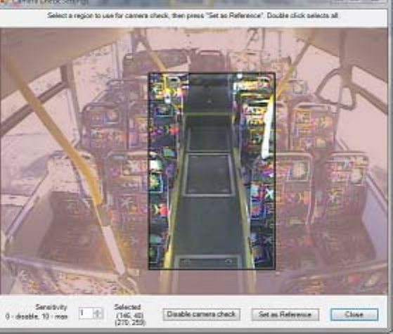
Chapter 3: Using Fleet Manager
50 MobileView Fleet Manager User Manual
4. Click Set as Reference. This will set a new reference image for future camera
checks and tests.
5. Click Close to exit the screen.
Viewing the status of a DVR during its latest
communication
The Operate tab displays information about the status of a selected DVR during
its last communication with the depot server.

Chapter 3: Using Fleet Manager
MobileView Fleet Manager User Manual 51
Figure 23: Operate tab
Table 20: Operate tab
Item Description
Vehicle name Contains the vehicle number.
Last location Contains the location of the vehicle when it last communicated
with the depot server.
Last online at depot Contains the last time that the DVR communicated with the
depot server.
Last shutdown reason Contains the reason for the last shutdown of the DVR.
System on time Contains the amount of time that the DVR system has been on
at the time the DVR last communicated with the server.
System record time Contains the amount of time that the DVR system has recorded
at the time the DVR last communicated with the server.
Images recorded Contains the number of images recorded in the last recording
period.
Images total size Contains the size of the images recorded during the last
recording period.
Average frame rate Contains the average recording period in the last recording
period.
GPS positions recorded Contains the number of GPS positions recorded during the last
recording period.

Chapter 3: Using Fleet Manager
52 MobileView Fleet Manager User Manual
Item Description
Startups Contains the total number of startup events, plus individual
totals for ignition, software, and maintenance startups.
Shutdown Contains the number of shutdowns, including the ignition,
power loss, software, watchdog, fault, maintenance, over
temperature, under temperatur, over voltage, under voltage,
and total.
Voltage source Contains the input voltage to the DVR for the last recording
period, including the minimum, average, and maximum.
Voltage 5 VDC Contains the voltage of the 5 V supply for the last recording
period, including the minimum, average, and maximum. This
setting is not used.
Voltage 12 VDC Contains the voltage of the 12 V supply for the last recording
period, including the minimum, average, and maximum.
Temperature - system Contains the temperature of the DVR for the last recording
period, including the minimum, average, and maximum.
MobileView Fleet Manager User Manual 53
Chapter 4
Troubleshooting and
support
Summary
This chapter provides information to help you troubleshoot problems and contact
technical support in case you need assistance with your equipment.
Content
Troubleshooting 54
Contacting us 54
Technical support 54
Online resources 55

Chapter 4: Troubleshooting and support
54 MobileView Fleet Manager User Manual
Troubleshooting
Failure Possible reasons
Job request failure. Wrong user name and password. Ensure that you have
the correct user name and password.
Autodownload job request failure. When entering autodownload jobs and the AutoArchiver
authentication box is checked, the system authenticates
with the server. If the user does not exist on the server
with administrator rights, the system ignores the
autodownload job.
Ensure the following:
• Date and time are set correctly on the server and
client initiating the request.
• Create autodownload jobs directly from the server.
• Check the AutoArchiver authentication box.
• Use the AutoArchiver user account to create the
job.
• Ensure that you do not create more than ten auto
download jobs at a time.
No vehicles are displaying in the main
window when searching for vehicles. Make sure the Vehicle box in the Vehicle List Filters
area of the Vehicle Management tab is clear of any
characters, including blank characters.
Contacting us
For help installing, operating, maintaining, and troubleshooting this product, refer
to this document and any other documentation provided. If you still have
questions, contact us during business hours (Monday through Friday, excluding
holidays, between 5 a.m. and 5 p.m. Pacific Time).
Technical support
North America
T 1 888 437.3287 (Toll-free in the US, Puerto Rico, and Canada)
Note: Be ready at the equipment before calling.

Chapter 4: Troubleshooting and support
MobileView Fleet Manager User Manual 55
Online resources
Here are some useful links on our website www.interlogix.com.
Link Description
Warranty and terms information From the Customer Support menu, select Return and
Warranty Policy Statement or Sales Terms and Conditions.
Customer service and technical
support From the Customer Support menu, select Customer Service
or Technical & Application . Select the appropriate product
category for the contact information or use the menu to
select a location outside the US.
Many UTC Fire & Security documents are provided in English only as PDFs. To read these
documents, you will need Adobe Reader, which you can download free from Adobe’s website at
www.adobe.com.
Chapter 4: Troubleshooting and support
56 MobileView Fleet Manager User Manual
MobileView Fleet Manager User Manual 57
Index
A
Accessing
Configuration Manager, 16
alarm events
autodownload of, 35
alarms
autodownloading, 35
downloading automatically, 35
alignment of camera, checking, 48
archive files
configuring display of, 16, 17
archiving
job output, 27
audio
storage on DVR, 42, 43
Auto Download Vehicle Events and Alarms
dialog box
information required, 35
AutoArchiver
installing, 6
AutoArchiver console window, image, 8
autodownloading
vehicle events and alarms, 35
autodownloading events and alarms, 35
C
camera, 48
camera checks
configuring, 24
configuring notifications, 24
Camera checks
autodownloading, 35
camera Checks tab
Notifications, 24
Camera Checks tab
frequency, 24
cameras
test images, viewing, 46
Cameras tab, image, 47
CCTV, 36
autodownloading, 35
requesting, 34
CCTV and Vehicle Data Management tab,
image, 37
checks, camera
configuring, 24
configuring notifications, 24
closing Fleet Manager, 12
color, use of, 17, 30
commands, 14
communicating with a depot server, 15
completed requests
viewing, 15, 37
Configuration Manager
configuring map display, 16, 17
Fleet Manager Display tab, image, 16
Job Management, 16, 17
Local Settings tab, image, 27
Message and Reporting tab, image, 25
opening, 16
path to Viewer, 16, 17
Server Status tab, image, 27
units, 16, 17
Vehicle Management, 14, 16, 30
Configuration Manager Message and
Reporting tab, information displayed on,
26
configuring
camera testing, 24
depot server, 18
depot server disk storage, 18, 19
depot server server, 18
display, 16
display of archive files, 17
e-mail settings, 18, 19
job failures, 21
job status reports, 26
jobs, 17, 21
local settings, 27
map display, 17
Index
58 MobileView Fleet Manager User Manual
notifications, camera testing, 24
path to Viewer, 16, 17
requests, 21
retries, 21
status report messages, 25, 26
units, 16, 17
vehicle status reports, 26
connecting to a depot server, 15
contact information, 54
D
data storage on DVRs, 42
depot
connecting to, 15
depot server
configuring, 18
connecting to, 15
Depot Server Settings tab
disk storage and management,configuring,
18, 19
email settings, 19
general settings, 19
Diagnostics tab, image, 44
Diagnostics tab, information displayed on, 44
disk storage, depot server
configuring, 18, 19
Display
configuring display of data, 16
Download
vehicle events and alarms, 35
downloading
vehicle events and alarms, 35
DVRs
data storage on, 42
E
e-mail messages
configuring, 21
e-mail settings
configuring, 18, 19
enable/disable
GraffitiDetect, 27
job copy feature, 27
Events, autodownloading, 35
exiting Fleet Manager, 12
F
Fleet Management System
menu commands, 14
Fleet Management System window
controls, 14
Fleet Management System window, image, 13
Fleet Manager Display tab
archive files management, 16, 17
configuring map display, 16, 17
Job Management, 16, 17
path to Viewer, 16, 17
units, 16, 17
Vehicle Management, 14, 16, 30
focus of camera, checking, 48
frequency
scheduling camera tests, 24
G
GPS data
storage on DVR, 43
sub, 41
graffiti on camera
checking for, 48
GraffitiDetect
enable/disable, 27
H
hardware requirements, 3
I
images
Viewing, 46
Installing
AutoArchiver, 6
Fleet Manager, 8
Interface tab, image, 46
J
job copy feature
enable/disable, 27
job failure
configuring, 21
job output
archiving, 27
Job Request and Transfer Management tab,
image, 32
Job Request and Transfer Management,
information displayed on, 33
job requests
video, 34
Job Settings tab
general, 21
job failure/retries, 21
notifications, 21
job status reports
configuring, 26
jobs
Index
MobileView Fleet Manager User Manual 59
configuring, 21
configuring display of, 16, 17
configuring general settings, 21
configuring job failure/retries, 21
L
Live tab, information displayed on, 41
local settings
configuring, 27
Local Settings tab, image, 27
Log files
autodownloading, 35
M
main
sub, 16, 17
Maintenance pane, 14
Cameras tab, image, 47
Diagnostics tab, image, 44
Diagnostics tab, information displayed on,
44
Interface tab, image, 46
Live tab, image, 41
Operate tab, image, 51
Operate tab, information displayed on, 51
Status tab, data storage on DVRs, 42
Status tab, image, 39
Status tab, information displayed on, 39, 42
Storage tab, image, 42
Management pane, 14
Job Request and Transfer Management
tab, image, 32
Job Request and Transfer Management,
information displayed on, 33
Vehicle Management tab, image, 29
Vehicle Management tab, information
displayed on, 29
Management pane, Maintenance pane, image,
13
map
configuring display of, 16, 17
menu commands, 14
Message and Reporting tab, image, 25
N
notification
of camera tests, configuring, 24
notifications
configuring, 21
O
Operate tab
information displayed on, 51
Operate tab, image, 51
P
path to Viewer
configuring, 16, 17
progressive backup of all vehicle data, 36
R
report messages
configuring, 25
reporting
configuring, 26
requesting
vehicle data, 36
video, 34
requests
automatic download, 35
configuring, 21
configuring display of, 16, 17
configuring general settings, 21
configuring job failure/retries, 21
viewing, 37
requirements, 3, 4
retries
configuring, 21
retrieving
all vehicle data, 36
S
scheduling camera tests, 24
Server Status tab, image, 27
Settings displayed on the Vehicle Management
tab, 29
starting Fleet Manager, 12
status
use of color to indicate, 30
status report messages
configuring, 25, 26
Status tab, Maintenance pane, 39
data storage on DVRs, 42
information on DVRs, 39
storage
depot server, configuring, 19
support, 54
system requirements, 3
Index
60 MobileView Fleet Manager User Manual
T
technical support, 54
test images
Viewing, 46
Tests
autodownloading, 35
tests, camera
configuring, 24
configuring notifications, 24
Tests, camera
configuring, 24
time
scheduling camera tests, 24
U
units, configuring, 17
User Data Request Form, information required,
34
V
vehicle data
configuring display of, 14, 16, 30
vehicle data, all
retrieving, 36
vehicle events
autodownload of, 35
autodownloading, 35
downloading automatically, 35
vehicle heading, 41
vehicle location, 41
vehicle position, latitude, 41
vehicle position, longitude, 41
vehicle speed, 41
vehicle status reports
configuring, 26
video
difficulty viewing remotely, 38
requesting, 34
storage on DVR, 42
viewing, 15, 37
Video
autodownloading, 35
Viewer
configuring path to, 17
Viewer, image, 38
viewing
requested video, 15, 37
test images, 46
