4661034 Itif Ultra Gard & Custom Versions Installation Instructions Apr 1997
2015-08-27
: InterLogix Ultragard & Custom Versions Installation Instructions Apr 1997 UltraGard & Custom Versions_Installation Instructions_Apr 1997 library
Open the PDF directly: View PDF ![]() .
.
Page Count: 64
- Special Installation Requirements
- Requirements for UL-Listed Installations
- Canada Listings
- California State Fire Marshall Listing
- Installing the System
- Determining the Panel Location
- Running Wires to the Panel Location
- Mounting the Panel
- Installing the Panel Antennas
- Wiring the Panel
- Setting the Optional Energy Saver Module (ESM), Hardwire Input Module (HIM) and Hardwire Output M...
- Installing the Backup Battery
- Powering Up the Panel
- Adjusting Status Sound Volume
- Programming the Panel
- Clearing Memory
- Entering and Exiting Program Mode
- Deleting Sensor Text
- Programming Sensor Text
- Adding (Learning) Wireless Sensors
- Adding (Learning) Hardwire Sensors
- Deleting Sensors and Hardwire Zones
- Programming Upper Sensors
- Programming Optional Feature Numbers
- Adding (Learning) Wireless Touchpads
- Programming Panel Configuration Options
- Programming the Primary Phone Number
- Programming the Phone Format
- Programming the Siren Time-out
- Programming the Install Code
- Programming the Account Number
- Programming the Entry Delay
- Programming the Extended Delay
- Programming the Exit Delay
- Programming the Activity Time-out
- Programming the House Code
- Programming the Energy Saver Module Freeze and Set Temperatures
- Programming the Touchpad Options
- Programming the Touchpad Unit Number
- Programming the Touchpad Quiet
- Programming Touchpad Key Beeps
- Programming the Interrogator 200 Audio Verification Module Mode, Time-out, and Access Code
- Programming HOM Points
- Programming the Time Zone
- Viewing or Programming the User-Programmable System Settings
- The Duress Code
- Adjusting the Alphanumeric Touchpad Display Brightness
- Requesting CS-4000/Downloader Programming
- Installing Line Carrier Devices
- Installing and Programming the Wireless Interior Siren (WIS)
- Setting the WIS DIP Switches and Installing the Battery
- Connecting an External Siren to the WIS
- Programming the WIS House Code
- Installing X-10 Lamp Modules
- Testing the System
- Testing Sensors
- If a Sensor Fails the Sensor Test
- Testing the Energy Saver Module (ESM)
- Testing the Hardwire Input Module (HIM)
- Testing the Hardwire Output Module (HOM)
- Testing the X-10 Lamp Modules
- Testing Phone Communication
- Testing Central Station Communication
- Displaying the Panel Version Code
- Appendix A: Command Summary
- User Operating Command Summary
- System Settings (User-Programming) Command Summary
- Appendix B: Troubleshooting
- Appendix C: Programming Tables
- Appendix D: System Planning Worksheets
- Appendix E: Panel Connections and Wiring
- Appendix F: UL Requirements

Contents
This document describes the basic procedures
necessary for an experienced installer to install, set
up, and program an UltraGard™ Security System.
[Check with your central station to verify they have
updated their CS-4000 with version 6.0 or later soft-
ware, for full UltraGard support.]
Installation Instructions
Document Number: 466-1034-01-ITI Rev. F
April 1997
Special Installation Requirements 1
Requirements for UL-Listed Installations 1
Canada Listings 1
California State Fire Marshall Listing 1
Installing the System 1
Determining the Panel
Location 2
Running Wires to the Panel Location 2
Mounting the Panel 2
Installing the Panel Antennas 3
Wiring the Panel 3
Setting the Optional Energy Saver Module
(ESM), Hardwire Input Module (HIM) and Hard-
wire Output Module (HOM) Unit Number DIP
Switches 4
Installing the Backup Battery 4
Powering Up the Panel 5
Adjusting Status Sound Volume 5
Programming the Panel 6
Clearing Memory 7
Entering and Exiting Program Mode 7
Deleting Sensor Text 8
Programming Sensor Text 8
Adding (Learning) Wireless Sensors 9
Adding (Learning) Hardwire Sensors 10
Deleting Sensors and Hardwire Zones 10
Programming Upper Sensors 11
Programming Optional Feature Numbers 11
Adding (Learning) Wireless Touchpads 11
Programming Panel Configuration Options 12
Programming the Primary Phone Number 12
Programming the Phone
Format 12
Programming the Siren
Time-out 13
Programming the Install Code 13
Programming the Account Number 13
Programming the Entry Delay 14
Programming the Extended Delay 14
Programming the Exit Delay 14
Programming the Activity Time-out 14
Programming the House Code 15
Programming the Energy Saver Module Freeze
and Set Temperatures 15
Programming the Touchpad Options 15
Programming the Touchpad Unit Number
16
Programming the Touchpad Quiet 16
Programming Touchpad Key Beeps 17
Programming the Interrogator 200 Audio Verifi-
cation Module Mode, Time-out, and Access Code
17
Programming HOM Points 18
Programming the Time Zone 18
UltraGard
and Custom Versions
Contents
Viewing or Programming the User-Programma-
ble System Settings 18
The Duress Code 19
Adjusting the Alphanumeric Touchpad Display
Brightness 20
Requesting CS-4000/Downloader Program-
ming 20
Installing Line Carrier Devices 21
Installing and Programming the Wireless Interior
Siren (WIS) 21
Setting the WIS DIP Switches and Installing
the Battery 21
Connecting an External Siren to the WIS 22
Programming the WIS House Code 22
Installing X-10 Lamp Modules 22
Testing the System 23
Testing Sensors 23
If a Sensor Fails the Sensor Test 24
Testing the Energy Saver Module (ESM) 24
Testing the Hardwire Input Module (HIM) 25
Testing the Hardwire Output Module (HOM) 25
Testing the X-10 Lamp Modules 25
Testing Phone Communication 26
Testing Central Station Communication 26
Displaying the Panel
Version Code 26
Appendix A: Command Summary 27
User Operating Command Summary 27
System Settings (User-Programming) Command
Summary 28
Appendix B: Troubleshooting 29
Appendix C: Programming Tables 37
Appendix D: System Planning Worksheets 42
Appendix E: Panel Connections and Wiring 50
Appendix F: UL Requirements 53
Notices
This manual may refer to products that are announced but are not yet available.
FCC Notices
This equipment has been tested and found to comply with the limits for a class B digital device, pursuant to part 15 of the FCC rules. These limits are designed to provide
reasonable protection against harmful interference in a residential installation. This equipment generates, uses, and can radiate radio frequency energy and, if not installed and
used in accordance with the instructions, may cause harmful interference to radio communications. However, there is no guarantee that interference will not occur in a particular
installation. If this equipment does cause harmful interference to radio or television reception, which can be determined by turning the equipment off and on, the user is en-
couraged to try to correct the interference by one or more of the following measures:
• Install a quality radio or television outdoor antenna if the indoor antenna is not adequate.
• Reorient or relocate the panel.
• Move the panel away from the affected equipment.
• Move the panel away from any wire runs to the affected equipment.
• Connect the affected equipment and the panel to separate outlets, on different branch circuits.
• Consult the dealer or an experienced radio/TV technician for help.
• Send for the FCC booklet How to Identify and Resolve Radio-TV Interference Problems, available from the U.S. Government Printing Office, Washington, D.C.
20402. Stock Number: 004-000-00345-4.
This device complies with part 15 of the FCC rules. Operation is subject to the following two conditions: (1) this device may not cause harmful interference, and (2) this
device must accept any interference received, including interference that may cause undesired operation.
This equipment complies with part 68 of the FCC rules. On the FCC label affixed to this equipment is the FCC Registration Number and Ringer Equivalence Number (REN)
for this equipment. If requested, provide this information to your telephone company.
The REN is used to calculate the maximum number of devices your telephone line will support with ringing service. In most areas the sum of all device RENs should not
exceed 5.0. Contact your local telephone company to determine the maximum REN for your calling area.
If your telephone equipment causes harm to the telephone network, your telephone company may temporarily disconnect your service. If possible, you will be notified in
advance. When advance notice is not practical, you will be notified as soon as possible. You will also be advised of your right to file a complaint with the FCC.
Your telephone company may make changes in its facilities, equipment, operations, or procedures that could affect the proper operation of your equipment. You will be given
advanced notice in order to maintain uninterrupted service.
If you experience trouble with this equipment, please contact
Interactive Technologies, Inc.
2266 Second Street North
North Saint Paul, MN 55109
1-800-777-1415
for service and repair information. The telephone company may ask you to disconnect this equipment from the network until the problem has been corrected or until you are
sure that the equipment is not malfunctioning.
This equipment may not be used on coin service provided by the telephone company. Connection to party lines is subject to state tariffs.
Canada Notice
The Canadian Department of Communications label identifies certified equipment. This certification means that the equipment meets certain telecommunications network pro-
tective, operational, and safety requirements. The department does not guarantee the equipment will operate to the user’s satisfaction.
Before installing this equipment, users should ensure that it is permissible to be connected to the facilities of the local telecommunications company. The equipment must also
be installed using an acceptable method of connection. In some cases, the company’s inside wiring associated with a single-line individual service may be extended by means
of a certified connector assembly (telephone extension cord). The customer should be aware that compliance with the above conditions may not prevent degradation of service
in some situations.
Repairs to certified equipment should be made by an authorized Canadian maintenance facility designated by the supplier. Any repairs or alterations made by the user to this
equipment, or equipment malfunctions, may give the telecommunications company cause to request the user to disconnect the equipment.
For your protection, make sure that the electrical ground connections of the power utility, telephone lines, and internal metallic water pipe system, if present, are connected
together.
Caution
Do not attempt to make connections yourself. Contact the appropriate electrician or electric inspections authority.
The Load Number (LN) assigned to each terminal device denotes the percentage of the total load to be connected to a telephone loop that is used by the device to prevent
overloading. The termination on a loop may consist of any combination of devices subject only to the requirement that the total of the LNs of all the devices does not exceed
100. Load Number: 0.4B

“AVIS: - L ´étiquette du ministère des Communications du Canada identifie le matériel homologué. Cette étiquette certifie que le matériel est conforme a certaines normes de
protection, d ´ exploitation et de sécurité des réseaux de télécommunications. Le ministère n ´ assure toutefois pas que le matériel fonctionnera a la satisfaction de l ´ utilisateur.
Avant d ´ installer ce matériel, l ´ utilisateur doit s ´ assurer qu´ il est permis de le raccorder aux installations de l ´ enterprise locale de télécommunication. Le matériel doit
également etre installé en suivant une méthod acceptée de raccordement. Dans certains cas, les fils intérieurs de l´ enterprise utilisés pour un service individuel a ligne unique
peuvent etre prolongés au moyen d´ un dispositif homologué de raccordement (cordon prolongateur téléphonique interne). L ´ abonné ne doit pas oublier qu ´ il est possible
que la conformité aux conditions énoncées ci-dessus n ´ empechent pas le dégradation du service dans certaines situations. Actuellement, les enterprises de télécommunication
ne permettent pas que l ´ on raccorde leur matériel a des jacks d ´ abonné, sauf dans les cas précis prévus pas les tarrifs particuliers de ces enterprises.
Les réparations de matériel homologué doivent etre effectuées pas un centre d ´ entretien canadien autorisé désigné par le fournisseur. La compagne de télécommunications
peut demander a l ´ utilisateur de débrancher un appareil a la suite de réparations ou de modifications effectuées par l ´ utilisateur ou a cause de mauvais fonctionnement.
Pour sa propre protection, l ´ utilisateur doit s ´ assurer que tous les fils de mise a la terre de la source d ´ énergie électrique, des lignes téléphoniques et des canalisations d ´´
eau métalliques, s ´ il y en a, sont raccordés ensemble. Cette précaution est particulièrement importante dans les régions rurales.
Avertissment. - L ´ utilisateur ne doit pas tenter de faire ces raccordements lui-meme; il doit avoir recours a un service d ´ inspection des installations électriques, ou
a electricien, selon le cas”.
Une note explicative sur les indices de charge (voir 1.6) et leur emploi, a l ´ intention des utilisateurs du matériel terminal, doit etre incluse dans l ´ information qui accompagne
le materiel homologué. La note pourrait etre rédigée selon le modèle suivant:
“L ´ indice de charge (IC) assigné a chaque dispositif terminal indique, pour éviter toute surcharge, le pourcentage de la charge totale qui peut etre raccordée a un circuit télé-
phonique bouclé utilisé par ce dispositif. La terminaison du circuit bouclé peut etre constituée de n ´ import somme des indices de charge de l ´ ensemble des dispositifs ne
dépasse pas 100.”
L ´ Indice de charge de cet produit est ____________.
Trademarks
ITI is a registered trademark of Interactive Technologies, Inc. UltraGard is a trademark of Interactive Technologies, Inc. X-10 is a registered trademark of X-10 (USA), Inc.

1
Special Installation
Requirements
This security system can be used as a fire warning
system, an intrusion alarm system, an emergency no-
tification system, or any combination of the three.
Some installations may require certain configurations
dictated by city codes, state codes, or insurance re-
quirements. The following information indicates the
components of various listings.
Requirements for UL-Listed
Installations
If the system is to comply with UL household require-
ments, there are specific guidelines you must follow.
Refer to appendix F for a list of compatible accesso-
ries, programming and wiring requirements in UL-
listed systems.
Canada Listings
The ULC (UL Canada) listing is pending.
CSA Certified Accessories
Residential Fire Warning System Control Unit
(ULC-S545-M89)
Basic system as described in appendix F for UL-listed
systems plus:
• Wireless Smoke Sensor (60-506), Wireless
Smoke Sensor (60-645-95), or Hardwire Smoke
Detector (13-360) (ESL 449AT) with Power
Supervision Module (60-391)
• Option F21 (Immediate Trouble Beeps) set ON
• SUPSYNC (Supervisory Synchronization) set to
2 (hours)
Note
SUPSYNC cannot be programmed from the panel. Refer to
the “Requesting CS-4000/Downloader Programming” sec-
tion for more information.
For 24-hour backup, external power drain is limited to 150
mA continuous using the heavy duty 6.5AH battery.
Residential Burglary Alarm System Unit
(ULC-S309)
Basic system as described in appendix F for UL-listed
installations plus:
• Learn Mode Door/Window Sensors (60-362)
California State Fire Marshall
Listing
The California State Fire Marshall listing is pending.
Installing the System
This section describes how to install the system con-
trol panel. Plan your system layout using the work-
sheets provided in appendix D before starting the
installation.
Installing the system consists of the following:
• Determining the Panel Location
• Running Wires to the Panel Location
• Mounting the panel
• Installing the panel antennas
• Wiring the panel
• Setting the optional Energy Saver and Hardwire
Input Module unit number dip switches
• Installing the backup battery
• Powering up the panel
• Adjusting status sound volume
Installing the System
2
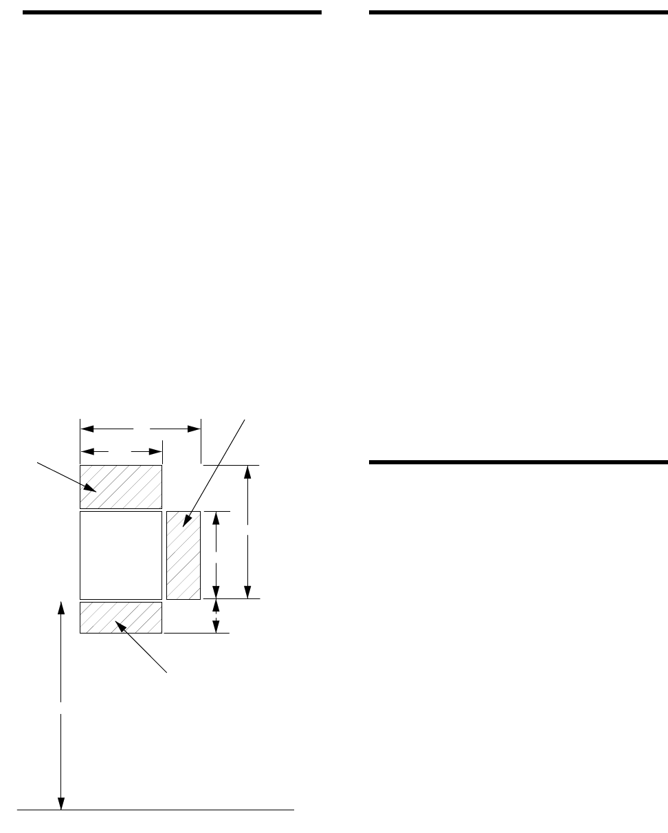
Determining the Panel
Location
Before permanently mounting the panel, determine
panel location using the following guidelines:
• Centrally locate the panel with relation to wire-
less sensor locations, whenever possible.
• Avoid locations with excessive metal such as
HVAC ducts, foil wallpaper, gas/water pipes, and
electrical wiring.
• Mount the panel at a comfortable working height
(about 45 to 55 inches from the floor to the bot-
tom of the panel, as shown in figure 1).
• Allow a minimum of 10.5 inches above the panel
for the antennas, as shown in figure 1.
• Allow 6.5 inches to the right or left of the panel
for wiring, phone jack, and optional module
mounting.
• Allow at least 24 inches in front of the panel for
access to panel components.
Figure 1 Determining Panel Location
Running Wires to the Panel
Location
Once you have determined the ideal panel location,
run any necessary wires to that location, including:
• Power transformer
• Phone line
• Sirens/speakers
• SuperBus* Alphanumeric Touchpads
• Hardwire zones
• Optional SuperBus* modules (such as Energy
Saver Module [ESM], Hardwire Input Module
[HIM], Hardwire Output Module [HOM], etc.)
* SuperBus is an improved technology bus configura-
tion and is not compatible with older bus modules.
Refer to table E.3 in appendix E for wire size and type
recommendations. If you are using the same cable
type for several wire runs, use labels to mark the wires
at the panel location to help identify these wires.
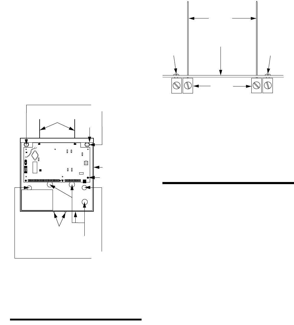
Mounting the Panel
Use the procedure below to mount the panel to the
wall or wall studs, using the supplied mounting hard-
ware and the panel mounting holes shown in figure 2.
Caution
Make sure you are free of static electricity whenever you
work on the panel with the cover removed. To discharge
any static, first touch the metal panel chassis, and then stay
in contact with the chassis when touching the circuit board.
An approved grounding strap is recommended.
To mount the panel:
1. Unlock the panel cover (if cover has a key lock
installed) or remove the panel cover retaining
screws at the bottom of the panel and remove the
panel cover.
2. Swing the panel cover out and up to remove it
from the enclosure.
3. Remove the necessary wiring knockouts. Be
careful not to damage the circuit board.
4. Place the enclosure in position against the wall.
PANEL
21"
14.5"
14.5"
25"
8"
45-55"
PHONE JACK AND
OPTIONAL MODULE
MOUNTING AREA
ANTENNA
AREA
ACCESS FOR
PANEL COVER
SCREWS
NOTE
ALLOW AT LEAST 24"
IN FRONT OF PANEL
FOR ACCESS TO PANEL
COMPONENTS
FLOOR
8557G04A.DS4
Installing the System
3
Make sure enclosure is level and mark the loca-
tions of the two mounting holes and two keyhole
mounting holes. Remember to leave room for the
panel antennas, which extend 9 inches above the
top of the enclosure.
5. Use the appropriate anchors and screws. Partially
insert screws into the two anchors at the two top
keyhole locations, and then hang the panel chas-
sis on the two screws.
6. Recheck for level, insert the two lower screws,
and then tighten all four mounting screws.
Figure 2 Mounting the Panel
Installing the Panel Antennas
Caution
You must be free of static electricity before handling elec-
tronic circuit boards. Touch a grounded, bare metal surface
before handling circuit boards to discharge yourself of static
electricity or wear a static grounding strap.
Insert one antenna into the inside screw terminal of
each terminal block and gently tighten the screws us-
ing a small pocket-size screwdriver (figure 3).
Figure 3 Installing the Panel Antennas
Caution
Do not overtighten the terminal block screws; if you do, per-
manent damage may result.
Wiring the Panel
Refer to appendix E for panel terminal descriptions,
wire recommendations, and typical system wiring di-
agram.
Refer to appendix F for panel programming and typi-
cal system wiring diagram for UL-listed installations.
Refer to appendix D, table D.2 to calculate the hard-
wire device power consumption for the system.
For more detailed information on installing hardwire
devices, refer to the installation instructions that ac-
company each device.
8557G08A.DS4
BACKUP
BATTERY
CONTROL
PANEL
CIRCUIT
BOARD
CONTROL
PANEL
ENCLOSURE
ANTENNAS COVER
LIP
KEYHOLE
MOUNTING
HOLES
MOUNTING
HOLES
WIRING
KNOCKOUTS
COVER
SCREWS
EARTH GROUND
CHASSIS SCREW
PANEL CIRCUIT BOARD
ANTENNA
TERMINAL
STRIPS
ENCLOSURE
ANTENNA
GROUNDING
SCREW
ANTENNA
GROUNDING
SCREW
ANTENNAS
8557G49A.DS4

Installing the System
4
Setting the Optional Energy
Saver Module (ESM), Hardwire
Input Module (HIM) and Hard-
wire Output Module (HOM)
Unit Number DIP Switches
All devices connected to the panel’s SuperBus hard-
wire bus have individual unit numbers assigned. Al-
phanumeric touchpad unit numbers are changed in
software during programming. The Energy Saver
Module (ESM), Hardware Input Module (HIM), and
Hardware Output Module (HOM) are set with DIP
switches inside the modules. For unit number setting
details, refer to the installation instructions provided
with the bus device.
Duplicated unit numbers will prevent those bus devic-
es from operating. Refer to table D.3 in appendix D
for recommended SuperBus device unit number set-
tings.
To set your ESM, HIM, or HOM unit number:
1. Set the module unit number DIP switches to the
desired unit number as shown the figure 4 per the
recommendations in table D.3 in appendix D.
The unit number is set to 0 (zero) at the factory
and is OK for most single touchpad and single
ESM, HIM, or HOM module applications. Make
sure that no bus devices (including hardwire
touchpads) share the same unit number (device
address).
Caution
The alphanumeric touchpad unit number defaults to 1 (one).
Do not set the ESM, HIM, or HOM unit number to 1. Doing
so will prevent the touchpad from functioning.
2. Turn the control panel power switch off and then
back on so the bus module can read the unit num-
ber switch settings into its memory.
3. Enter and exit PROGRAM MODE by switching
the panel PROGRAM/RUN switch to PRO-
GRAM and back to RUN so the panel can
“learn” the new bus device unit numbers.
If the alphanumeric touchpad (or other SuperBus de-
vice) no longer seems to function, check if the same
unit number assigned is to more than one device. Su-
perBus devices cannot share the same unit number.
Figure 4 Setting the ESM, HIM, or HOM Unit Num-
ber Dip Switches
Note
All SuperBus devices such as Energy Saver, Hardwire In-
put, and Hardwire Output Modules and alphanumeric touch-
pads must have unique unit number (address) settings.
Devices with the same (conflicting) address will not function
properly. Module address switches 1–5 must remain down
(off).
Installing the Backup Battery
The panel uses one rechargeable, sealed 12V lead-
acid backup battery.
Note
Both standard (60-681) 12V, 4AH and heavy duty (60-680)
12V, 6.5AH backup batteries are available. Always replace
with the same battery type and size.
8557G32A.DS4
UNIT NUMBER 0
UNIT NUMBER 1
UNIT NUMBER 2
UNIT NUMBER 3
UNIT NUMBER 4
UNIT NUMBER 5
UNIT NUMBER 6
UNIT NUMBER 7
678
12345
678
12345
678
12345
678
12345
678
12345
678
12345
678
12345
678
12345

Installing the System
5
To install (or replace) the backup battery:
1. Make sure the panel power switch is OFF and
that the transformer is unplugged from the outlet.
While AC power is applied to the panel, the
charging voltage is present at the battery leads
even with the power switch off.
2. Verify all wiring at the panel and devices for cor-
rect terminations.
3. Place the battery in the lower left or right portion
of the panel enclosure, with the terminals facing
up.
4. Connect the supplied black battery wire from the
panel circuit board negative (-) battery spade lug
(located near the power switch) to the negative (-
) battery terminal.
5. Connect the red battery wire from the panel cir-
cuit board positive (+) battery spade lug to the
positive (+) battery terminal.
WARNING!
Never short-circuit or reverse the battery wires. Possi-
ble injury to you and/or permanent damage to the panel
could result.
Powering Up the Panel
After wiring all devices to the panel and installing the
backup battery, you are ready to power up the panel.
Note
If the installation includes more than one alphanumeric
touchpad, disconnect all but one from their wiring harness-
es to reduce the possibility of a unit number (address) con-
flict. When powering up and programming are completed,
connect the remaining touchpads to their wiring harnesses.
For complete details on adding additional alphanumeric
touchpads to a working system, refer to the
SuperBus Al-
phanumeric Touchpad Installation Instructions
included
with each touchpad.
To power up the panel:
1. Plug the transformer into an outlet that is not
controlled by a switch.
2. Make sure the panel PROGRAM/RUN switch
located between the two panel terminal strips is
set to RUN (up).
3. Turn ON the panel power switch located on the
left edge of the panel and note the following:
The green power LED on the panel turns on.
Interior sirens and piezos sound one beep and in-
terior speakers announce the message Alarm sys-
tem is off.
Alphanumeric touchpad displays 1 - OFF.
Note
If the power LED is off or flashing and no beeps or voice
messages sound, turn off the panel power switch, discon-
nect the backup battery, and unplug the transformer. Refer
to appendix B, “Troubleshooting.”
4. Turn the panel power switch OFF, unplug the
transformer, and remove the existing screw
securing the AC outlet cover.
WARNING!
Use extreme caution when securing the transformer to
a metal outlet cover. You could receive a serious shock
if a metal outlet cover drops down onto the prongs of
the plug while you are securing the transformer and
cover to the outlet box.
5. Hold the outlet cover in place and plug the trans-
former into the lower receptacle.
6. Use the screw supplied with the transformer to
secure the transformer to the outlet cover.
7. Turn the panel power switch ON.
Adjusting Status Sound
Volume
The panel allows you to set the volume level for status
sounds and status messages from speakers connected
to panel terminals 8 and 9 (VOICE). Alarm sounds
and messages are preset to full volume.
To adjust the status sound volume:
1. Locate the speaker volume adjustment potenti-
ometer on the panel (above terminal 8).
Caution
Never adjust the potentiometer labeled “Do Not Adjust” lo-
cated near the power switch. Permanent damage to the
panel could result.
Programming the Panel
6
2. Press STATUS + STATUS on the alphanumeric
touchpad for a long system status display and
voice message.
Note
User-programmable system setting 77 (Quiet Exit) must be
off for voice sounds to be announced. (See Viewing or Pro-
gramming the User-Programmable System Settings.)
3. While listening to the message, increase the vol-
ume level by turning the volume potentiometer
clockwise.
4. Repeat steps 2 and 3 until the desired volume
level is reached.
Programming the Panel
The alphanumeric touchpad is the main programming
device for the system on-site. This touchpad is used to
enter values into panel memory, such as sensors, sen-
sor text, and system-specific configuration informa-
tion. During programming, the alphanumeric
touchpad prompts you for information in a certain or-
der. You can cycle through this order of prompts to
get to the desired programming area. For example,
you can cycle past the prompts for sensor text to enter
the system configuration information and later return
to programming sensor text.
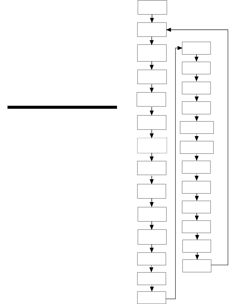
Figure 5 shows the order of the prompts, and the area
of programming related to these prompts. Once you
know this order of prompts, you will be able to move
forward and backward in the prompt sequence to lo-
cate the programming item you need.
Examine the flowchart shown in figure 5 to familiar-
ize yourself with the sequence in which the program-
ming procedures appear. The programming software
is like a menu of choices displayed in a scroll. The di-
rection of the chart arrows represents pressing the
BYPASS button to scroll forward. To scroll back-
ward, press the STATUS button. You can also go di-
rectly to the menu choice by entering the two-digit
number shown.
When you use the alphanumeric touchpad to program
the system, the touchpad buttons have special pro-
gramming meanings and functions. Table 1 describes
the programming buttons.
Figure 5 Programming Flow Chart
AVM
TIME-OUT
AVM MODE
TOUCHPAD
OPTIONS
ACTIVITY
TIME-OUT
HOUSE
CODE
FREEZE
TEMPERATURE
SET
TEMPERATURE
EXIT DELAY
EXTENDED
DELAY
ENTRY
DELAY
ACCOUNT
NUMBER
PHONE
NUMBER
PHONE
FORMAT
SIREN
TIME-OUT
INSTALL
CODE
8557G45B.DS4
22
20
19
18
17
16
15
14
13
12
11
10
09
08
LEARN
SENSORS
DELETE
SENSORS
UPPER
SENSORS
LEARN
TOUCHPADS
07
05
04
03
F
OPTIONS
06
21
PROGRAM
MODE
DELETE
TEXT
01
PROGRAM
SENSOR
TEXT
02
AVM CODE
23
HOM
SETUP
24
25
TIME
ZONE

Programming the Panel
7
Programming the panel includes the following proce-
dures:
• Clearing memory
• Entering and exiting program mode
• Deleting and programming sensor text
• Adding and deleting wireless sensors and hardwire
zones
• Programming upper sensor numbers
• Programming optional feature numbers
• Adding wireless touchpads
• Programming panel configuration options
• Programming the phone number and format
• Programming the siren time-out
• Programming the install code
• Programming the account number
• Programming the entry, extended, and exit delays
• Programming the activity time-out
• Programming the house code
• Programming the freeze and set temperatures
• Programming the touchpad options
• Programming the Audio Verification Module
mode, time-out, and access code
• Programming HOM Setup
• Programming the Time Zone
• Viewing or programming the user-programmable
system settings
• The duress code
• Adjusting the alphanumeric touchpad display
brightness
• Requesting CS-4000/Downloader programming
Note
All on-site programming must be done using a SuperBus Al-
phanumeric Touchpad. The Alphanumeric Touchpad can
be removed once the system has been programmed.
Clearing Memory
Clear memory on all newly installed panels before
programming.
Note
Since all programming information is contained in memory,
clearing memory deletes all existing programming informa-
tion except sensor text (if any). Sensor text can be deleted
separately.
To clear panel memory:
1. Open and remove the panel door.
2. Turn the panel power switch OFF and then ON.
3. Immediately (within 1 minute after turning panel
power ON), press and hold the memory clear
button located on the upper left edge of the panel
until a relay click is heard at the panel or until
interior speakers announce Memory good-bye.
Entering and Exiting Program
Mode
The panel must be in program mode to perform any of
the on-site programming operations.
Table 1 Alphanumeric Touchpad
Programming Button Functions
Button Programming Function
Numeric
Buttons Used to enter numeric values such as
delays and sensor numbers. Also used
to enter text characters or word codes
during sensor text programming.
STATUS Scrolls backward to previous program-
ming function. Displays previous sensor
text library character during sensor text
programming. Also used to “lock in” new
alphanumeric touchpad unit numbers.
BYPASS Scrolls forward to next programming
function. Displays next sensor text
library character during sensor text pro-
gramming.
COMMAND Used to proceed or confirm displayed
entry. Displays next character/word posi-
tion in sensor text programming. Also
used to toggle between values, such as
yes/no or on/off.
FIRE Cancels and exits displayed program-
ming command (if pressed before COM-
MAND).
Backs out to previous menu level.
AUXILIARY Scrolls long display messages.
POLICE Used to clear (blank) an access code.
Used to program a pause in central sta-
tion phone number.
Used to clear HOM points.

Programming the Panel
8
To enter program mode:
1. Open and remove the panel door.
2. Set the panel PROGRAM/RUN switch to PRO-
GRAM (down).
Alphanumeric touchpads display PROGRAM MODE
and interior speakers, sirens, and piezos sound six
beeps every minute as a reminder that the panel is in
the program mode.
Note
If touchpad(s) do not display
PROGRAM MODE
after
switching the PROGRAM/RUN switch to PROGRAM
(down), a special install code has been programmed into
the panel and now must be entered into the touchpad using
the number buttons. The touchpad will display
PROGRAM
MODE
once the correct install code is entered.
The program mode of operation must be exited for the
system to operate normally (RUN). You can exit from
program mode at any time.
To exit program mode:
1. Switch the panel PROGRAM/RUN switch to
RUN (up).
2. The alphanumeric touchpad will display 1 - OFF
to signal that the system is in the normal mode of
operation.
3. When you are finished programming or working
in the control panel, replace and secure the panel
door with either the panel door screws or key
lock.
Deleting Sensor Text
You can delete all sensor text (if any)—before pro-
gramming or reprogramming, for example—by doing
the following procedure.
To delete all existing sensor text:
1. In PROGRAM MODE, press BYPASS or STA-
TUS until DELETE TEXT is displayed.
2. Press COMMAND. Flashing RDY is displayed.
Caution
Deleted text cannot be retrieved and must be repro-
grammed.
3. Press POLICE to delete all sensor text. DELETE
TEXT DONE is displayed.
4. Press FIRE to exit.
Programming Sensor Text
This section describes how to program sensor names.
Use the word and character numbers you recorded in
appendix D (using table C.2 in appendix C) to pro-
gram sensor text.
Before programming sensor text the first time, delete
all existing text (if any) as detailed above.
To program sensor text:
1. In PROGRAM MODE, press BYPASS or STA-
TUS until the display reads PROG SENSOR
TEXT.
2. Press COMMAND and the display reads S01
[Group number assigned, if any] [“-” if nor-
mally closed, “*” if normally open] [existing
sensor text, if any].
3. Enter the desired sensor number from 01 to 76
and the display reads S## [existing sensor text, if
any].
4. Press COMMAND and the display reads A 00.
5. Enter the appropriate word number or character
number from table C.2 in appendix C.
6. Press COMMAND and the display reads B 00.
7. Repeat steps 5 and 6 until the whole sensor name
is entered.
Note
Because the touchpad can only display a limited number of
characters, in some cases—such as alarms—all text may
not be displayed.
8. Press FIRE. The display shows the sensor num-
ber and name. Lines longer than the display will
scroll horizontally. If desired, press AUXIL-
IARY to scroll the long-line display again.
9. Press BYPASS to cycle to the next sensor num-
ber and repeat steps 4 through 8 until all sensor
names are programmed.
10. Press FIRE to exit.

Programming the Panel
9
Adding (Learning) Wireless
Sensors
Programming wireless and hardwire sensors involves
switching the panel to the program mode of operation
and setting sensor identification numbers and group
numbers for each wireless sensor and hardwire sensor
loop. Once sensors IDs and group assignments are
added (learned) into panel memory, the panel can re-
spond appropriately for each sensor detection. Sen-
sors can be added (learned) into or deleted from panel
memory.
Use table C.1 in appendix C for selecting sensor
groups and complete the group assignment for each
wireless sensor in the system planning worksheets in
appendix D.
Use the following procedure to add (learn) all Learn
Mode wireless sensors.
To add Learn Mode wireless sensors into panel
memory:
1. In PROGRAM MODE, press the touchpad
BYPASS or STATUS button repeatedly until
LEARN SENSOR is displayed.
2. Press the COMMAND button to display
GROUP __ __.
3. Enter the desired group number (00 to 29, 32).
4. Press the COMMAND button to display SEN-
SOR ##.
5. Press the COMMAND button if the sensor num-
ber displayed is OK or enter another number
from 01 to 76, and then press COMMAND
again.
6. The display reads TRIP - ##. Trip the wireless
sensor tamper switch as shown in table 2 or as
described in the sensor’s installation instructions.
When the sensor has been added (learned) the
display reads TRIP - ## [next #] and interior
speakers announce Sensor # okay. Sensor [next #
to be learned].
Note
To trip a wireless sensor with an external hard-wire contact
connected to its screw terminals, check that the external
contact is in its alarm state, and then trip the sensor.
The alarm state is either open or closed, depending on the
normal condition of the sensor. Multiple normally closed
switches are wired in series and tripped while the loop is
open. Multiple normally open switches are wired in parallel
and tripped while the loop is closed.
For high-security installations, always remove both internal
reed switches when connecting an external contact to the
wireless sensor terminals.
Only the normally closed configuration can be used in UL-
listed installations.
Do not attempt to use the built-in reed switch
and
an exter-
nal contact on the same wireless sensor.
7. Continue adding sensors into the current group
number by repeating step 6 for each sensor. Press
BYPASS, STATUS, or number buttons to select
new sensor numbers (other than what is automat-
ically displayed).
8. To add sensors into other groups, press FIRE
and follow steps 3 through 7.
Table 2 Tripping Learn Mode Wireless
Sensors
Sensor * Action
Door/Window †Open sensor cover.
Fire Pull Station Open the sensor cover located
inside the Fire Pull Station.
Freeze Open sensor cover.
Glass Guard Open sensor cover.
Portable Emergency But-
tons Press the appropriate emer-
gency button(s).
PIR Motion Open PIR case.
Keychain Touchpad Simultaneously press arm and dis-
arm until the LED flashes.
Rate-of-Rise Heat Open sensor cover and press learn
switch on circuit board.
Recessed Door/Window Open sensor cover and remove
transmitter circuit board.
Shock †Open sensor cover.
Slim Line Door/Window Remove sensor from mounting
base.
Sound Open sound sensor cover, after
spring is installed.
System Sensor Smoke
System Sensor 2300RF ITI
Press test button and hold for
30 seconds, until test alarm
begins sounding.
With sensor removed from base,
press the test button for at least
1 second.
* Refer to the particular sensor’s installation instructions for
more details on tripping Learn Mode wireless sensors.
† When using an external contact with this sensor, the contact
must be in the alarm state while tripping the sensor to properly
learn it into memory.

Programming the Panel
10
9. Press FIRE to exit. Proceed to your next pro-
gramming task.
10. If you are finished programming, switch the
panel PROGRAM/RUN switch to RUN (up).
The touchpad will display 1 - OFF to signal that
the system is in the normal (RUN) mode of oper-
ation.
Adding (Learning) Hardwire
Sensors
After planning the installation, use table C.1 in appen-
dix C to select sensor groups and complete the group
assignment for each wireless sensor in the system
planning worksheets in appendix D.
Use the following procedure to add (learn) all hard-
wire sensors and zones into panel memory.
To add (learn) hardwire sensors:
1. Place all hardwire sensors in their normal (non-
alarm) state.
2. In PROGRAM MODE, press the touchpad
BYPASS or STATUS button repeatedly until
LEARN SENSOR is displayed.
3. Press the COMMAND button to display
GROUP __ __.
4. Enter the desired group number (00 to 29, 32).
5. Press the COMMAND button to display SEN-
SOR ##.
6. Press the COMMAND button if the sensor num-
ber displayed is correct or enter another number
from 01 to 76, and then press COMMAND
again.
7. The display reads TRIP - ##. Trip the sensor by
placing it into the alarm state (open the door or
window) or as described in the sensor’s installa-
tion instructions. The display reads TRIP - ##
[next #] and interior speakers announce Sensor #
okay. Sensor [next # to be learned].
Note
The alarm state is either open or closed, depending on the
normal condition of the sensor. Multiple normally closed
switches are wired in series and tripped while the loop is
open. Multiple normally open switches are wired in parallel
and tripped while the loop is closed.
On hardwire zones containing multiple sensors, only one
sensor per zone needs to be added (learned) into panel
memory.
If the system uses hardwire sensors only, turn off upper
sensor 94 (Receiver Failure) in the panel.
Only the normally closed configuration can be used in UL-
listed installations.
8. Continue adding sensors into the current group
number by repeating step 7. Press BYPASS,
STATUS, or number buttons to select new sen-
sor numbers.
9. To add sensors into other groups, press FIRE
and follow steps 4 through 8.
10. Press FIRE to exit. Proceed to your next pro-
gramming task.
11. If you are finished programming, switch the
panel PROGRAM/RUN switch to RUN (up).
The touchpad will display 1 - OFF to signal that
the system is in the normal (RUN) mode of oper-
ation.
Deleting Sensors and Hard-
wire Zones
If you want to reassign a sensor or hardwire zone to
another group, you must first delete that sensor or
zone.
To delete a sensor from the panel:
1. In PROGRAM MODE, press STATUS or
BYPASS until the display reads DELETE SEN-
SOR.
2. Press COMMAND and the display reads
DELETE ## [sensor text, if any].
Note
After pressing COMMAND in step 2, the display shows the
lowest programmed sensor number.
3. If the sensor number displayed is not correct,
enter the desired number (01 to 76).
4. Press COMMAND and the display reads DEL
## OK.
5. Continue deleting sensors by repeating steps 3
and 4.

Programming the Panel
11
6. Press FIRE to exit.
Note
Sensor text is not deleted when its sensor is deleted.
Programming Upper Sensors
Upper sensors are optional values (see appendix D,
table D.7) you turn on or off depending on your cus-
tomer’s equipment and needs.
Note
We recommend that you do not change upper sensors that
default ON. Factory default settings will work for most appli-
cations.
Use the settings recorded in appendix D, table D.7
when programming upper sensors.
To program upper sensor numbers:
1. In PROGRAM MODE, press BYPASS or STA-
TUS until UPPER SENSOR is displayed.
2. Press COMMAND and the display reads 77 -
OFF TOUCHPAD TAMPER. (Press AUXIL-
IARY to scroll any long messages sideways.)
3. Press COMMAND to toggle upper sensor 77
ON, if desired, or press BYPASS to cycle to the
next upper sensor.
Note
To jump directly to a particular upper sensor, enter its two-
digit number instead of pressing BYPASS.
4. Repeat step 3 until all upper sensors are pro-
grammed to suit the installation.
5. Press FIRE to exit.
Programming Optional
Feature Numbers
Optional feature numbers are system features (see ap-
pendix D, table D.8) you turn on or off depending on
your customer’s needs.
Note
We recommend that you do not change feature numbers
that default ON. Factory default settings will work for most
applications.
Use the settings recorded in table D.8 when program-
ming optional feature numbers.
To program feature numbers:
1. In PROGRAM MODE, press BYPASS or STA-
TUS until F OPTIONS is displayed.
2. Press COMMAND to display 00 - ON REMOTE
ACCESS. (Press AUXILIARY to scroll long
messages in the display.)
3. Press COMMAND again to toggle the feature
number ON or OFF as desired.
4. Press BYPASS to display the next feature num-
ber.
Note
To jump directly to a particular feature number, enter its
number instead of pressing BYPASS.
5. Repeat steps 3 and 4 for all of the remaining fea-
ture numbers.
6. Press FIRE to exit.
Adding (Learning) Wireless
Touchpads
You can add up to four wireless touchpads to the sys-
tem (including keychain touchpads).
To add (learn) wireless touchpads:
1. In PROGRAM MODE, press BYPASS or STA-
TUS until LEARN TOUCHPAD is displayed.
2. Press COMMAND to display PRESS BYP TP -
1.
3. Press BYPASS on the wireless touchpad (press
and hold both lock and unlock buttons on the
wireless keychain touchpad) until the display
reads PRESS BYP TP 2 and One OK, Two is
heard.
4. Repeat step 3 for each wireless touchpad until
they are all added.
5. Press FIRE to exit.

Programming the Panel
12
Caution
After exiting from learning touchpads, reentering the learn
touchpads menu by pressing COMMAND automatically de-
letes all learned touchpads. When adding wireless touch-
pads to the system, you must also relearn existing
touchpads.
Programming Panel
Configuration Options
This section describes how to program the following:
• Primary phone number and phone format
• Siren time-out
• Install code
• Account number
• Entry, extended, and exit delays
• Activity time-out
• House code
• Energy Saver Module (ESM) freeze and set tem-
peratures
• Touchpad unit number, quiet, and key beeps
options
• Audio Verification Module (AVM) mode, time-
out, and code
• HOM setup
• Time zone
• User-programming system settings
• Duress code
Use the panel configuration settings you recorded in
table D.5 to program the system.
Programming the Primary
Phone Number
The panel can report alarms and all other reports to a
central monitoring station by programming the prima-
ry phone number (or central station’s phone number)
into panel memory. The default phone number is
blank (none).
To program the central monitoring station tele-
phone number:
1. In PROGRAM MODE, press BYPASS until the
display reads PHONE NUMBER.
2. Press COMMAND. The display shows [existing
phone number, if any].
3. Enter the central station receiver phone number
(up to 18 digits). If you need a pause between
digits, press POLICE for each 1-second pause
desired.
4. Press COMMAND. The display reads [new
phone number].
5. Press FIRE to exit.
Programming the Phone
Format
The phone format determines the type of communica-
tion the panel uses to report to the central monitoring
station’s receiver. The default phone format is “ITI.”
To program the panel telephone format:
1. In PROGRAM MODE, press BYPASS until the
display reads PHONE FORMAT.
2. Press COMMAND to display the currently
selected format. For example, ITI FMT.
3. Press BYPASS or STATUS to cycle to the
desired setting: SET ITI, -1400, or -2300.
Note
Phone format must be set to “ITI” for the panel to correctly
communicate with the ITI ToolBox Downloader.
4. Press COMMAND and the display reads SET
[selected format] OK.
5. Press FIRE to exit.

Programming the Panel
13
Programming the Siren
Time-out
The siren time-out determines how long sirens sound
an alarm condition, if no one is present to disarm the
system. The default siren time-out is 4 minutes.
To program a different siren time-out:
1. In PROGRAM MODE, press BYPASS until the
display reads SIREN TIMEOUT.
2. Press COMMAND and the display reads SIREN
- ## MIN.
3. Enter the desired two-digit time (01 to 30 min-
utes).
4. Press COMMAND and the display reads SIREN
- ## MIN.
5. Press FIRE to exit.
Programming the Install Code
The install code is a special access code used to pre-
vent accidental or unauthorized changes to system
programming. The default install code is blank
(****).
Caution
Always install and test all wired touchpads before entering
an install code. Programming an install code before all
touchpads are installed and tested is risky. It can lead to a
situation where memory must be cleared to get into pro-
gram mode. This can happen if a bus conflict renders the al-
phanumeric touchpad useless (and there are no wireless
touchpads and phone control is turned off). In this situation,
there is no way to enter an install code—there is no way to
get back into the program mode except to erase the install
code (and all other programming) by clearing memory.
If an install code is desired, program it after installation is
complete and just before you leave the site.
Note
Once an install code is entered, it will start a 1-hour timer.
For the next hour, the install code will not be required. This
timer is cleared by entering dealer sensor test.
To program an install code:
1. In PROGRAM MODE, press BYPASS until the
display reads INSTALL CODE.
2. Press COMMAND to display INSTALL - ****.
3. Enter any four digits from 0001 to 9998.
Note
See table D.6 in appendix D for code number defaults and
restrictions.
To return the install code to blank (****) press the POLICE
button instead of a four-digit code.
4. Press COMMAND. INSTALL - #### is dis-
played.
5. Press FIRE to exit.
Programming the Account
Number
The account number is a five-character panel identifi-
cation for central monitoring stations. Used when the
panel sends reports. The default account number is
00-000.
To program an account number:
1. In PROGRAM MODE, press BYPASS until the
display reads ACCOUNT NUMBER.
2. Press COMMAND to display ACCOUNT -
#####.
3. Enter any five digits.
4. Press COMMAND. ACCOUNT - ##### is dis-
played.
5. Press FIRE to exit.
Note
Only numbers can be programmed locally though the alpha-
numeric touchpad. Letters can be programmed though the
CS-4000 or Downloader and will display correctly with the
panel in program mode.

Programming the Panel
14
Programming the Entry Delay
The entry delay determines the time a user has to enter
the premises and disarm the system, before it goes
into alarm. The default entry delay is 32 seconds.
To program a different entry delay:
1. In PROGRAM MODE, press BYPASS until the
display reads ENTRY DELAY.
2. Press COMMAND and the display reads ENTRY
- ### SEC.
3. Enter the desired three-digit time (008 to 120
seconds).
Note
The system automatically rounds off the entry to the nearest
multiple of eight.
4. Press COMMAND and the display reads ENTRY
- ### SEC.
5. Press FIRE to exit.
Programming the Extended
Delay
The extended delay affects both entry and exit delay
times for sensors in groups 11 (extended delay) and
12 (twice extended delay). The extended delay setting
determines how much time system users have to leave
the premises after arming and how much time users
have to disarm after entering, without causing an ac-
cidental alarm. The default extended delay is 4 min-
utes.
To program a different extended delay:
1. In PROGRAM MODE, press BYPASS until the
display reads EXTENDED DELAY.
2. Press COMMAND. The display reads DELAY -
## MIN.
3. Enter the desired two-digit time (01 to 08 min-
utes).
4. Press COMMAND and the display reads
DELAY - ## MIN.
5. Press FIRE to exit.
Programming the Exit Delay
The exit delay determines how much time system us-
ers have to leave the premises through a designated
delay door without causing an alarm, after arming the
system. The default exit delay is 32 seconds.
To program the exit delay:
1. In PROGRAM MODE, press BYPASS until the
display reads EXIT DELAY.
2. Press COMMAND and the display reads EXIT -
### SEC.
3. Enter the desired three-digit time (008 to 184
seconds).
Note
The system automatically rounds off the entry to the nearest
multiple of eight.
4. Press COMMAND and the display reads EXIT -
### SEC.
5. Press FIRE to exit.
Programming the Activity
Time-out
The activity time-out determines how many hours of
system non-use are sensed, before sending a report to
the central monitoring station. The default activity
time-out is 24 hours.
To program a different activity time-out:
1. In PROGRAM MODE, press BYPASS until the
display reads ACTIVITY TIMEOUT.
2. Press COMMAND to display ACTIVITY - ## H.
3. Enter the desired two-digit time (01 to 24 hours).
4. Press COMMAND. ACTIVITY - ## H is dis-
played.
5. Press FIRE to exit.
Note
Upper sensor S79 (No Activity) must be on for the activity
timer to function. S79 default is off.

Programming the Panel
15
Programming the House Code
The house code is a three digit number used to com-
municate panel signals to line carrier devices such as
Wireless Interior Sirens (WIS) and X-10 Lamp and
Appliance Modules. The default house code is 001(X-
10 module house code “B”).
To program a different house code:
1. In PROGRAM MODE, press BYPASS until the
display reads HOUSE CODE.
2. Press COMMAND to display HOUSE CODE -
### [X-10 module unit code A–P].
3. Enter the desired three digit house code number
(001 to 254).
4. Press COMMAND. HOUSE CODE - ### [X-10
module unit code A–P] is displayed.
5. Press FIRE to exit.
Programming the Energy
Saver Module Freeze and Set
Temperatures
The freeze temperature setting determines when the
Energy Saver Module’s freeze sensor activates,
sounding interior sirens and reporting to the central
monitoring station. The default freeze temperature is
42° F.
Note
Upper sensor 78 (Freeze Sensor) must be ON to enable the
freeze alarm. Upper sensor 78 defaults to OFF.
To program the Energy Saver Module freeze tem-
perature:
1. In PROGRAM MODE, press BYPASS until the
display reads FREEZE TEMP.
2. Press COMMAND and the display reads
FREEZE TEMP - ##.
3. Enter the desired two-digit temperature (40 to
90).
4. Press COMMAND and the display reads
FREEZE TEMP - ##.
5. Press FIRE to exit.
The Energy Saver Module set (readout) temperature
setting lets you adjust the module to match the on-pre-
mises thermostat. The default set temperature is the
unadjusted ESM temperature.
To adjust the Energy Saver Module temperature
readout, make sure that the module is wired and
working, then:
1. In PROGRAM MODE, press BYPASS until the
display reads SET TEMP.
2. Press COMMAND to display TEMPERATURE
- ##.
3. Enter present two-digit room temperature (32 to
99).
4. Press COMMAND and the display reads TEM-
PERATURE - ##.
5. Press FIRE to exit.
Programming the Touchpad
Options
The touchpad options setting lets you set the touchpad
unit number, touchpad quiet, and touchpad key beeps
options.
To program the alphanumeric touchpad options:
1. In PROGRAM MODE, press BYPASS until
TOUCHPAD OPTIONS is displayed.
2. Press COMMAND to display UNIT NUMBER.
3. Press BYPASS to display the various touchpad
options.
4. Continue with the following touchpad option
procedures.

Programming the Panel
16
Programming the Touchpad
Unit Number
The touchpad unit number lets the panel identify spe-
cific touchpads connected to the bus. Each alphanu-
meric touchpad must be assigned a unit number,
different than any other bus device. Use the following
guidelines when changing touchpad unit numbers:
• Always start with one touchpad connected to the
panel and get it operational with the panel, before
connecting additional touchpads.
• Whenever possible, such as in new installations,
assign alphanumeric touchpad unit numbers
before all other panel programming.
• Always work from one touchpad location when
assigning unit numbers for installations with
multiple touchpads.
For complete details on installing additional alphanu-
meric touchpads to a working system, refer to the Su-
perBus Alphanumeric Touchpad Installation
Instructions included with each touchpad.
The default touchpad unit number is 001.
Note
On systems with multiple alphanumeric touchpads, the fol-
lowing procedure puts all touchpads into the address set
mode.
Caution
Always delete (blank) the install code before adding wired
touchpads or changing wired touchpad unit (address) num-
bers. The default install code is blank (****).
Programming an install code before all touchpads are in-
stalled and tested may prevent correct touchpad installation
and may require clearing memory and reprogramming. If an
install code is desired, program it after installation is com-
plete and just before you leave the site.
To delete (blank) the install code prior to changing
the touchpad unit number:
1. In PROGRAM MODE, press BYPASS until the
display reads INSTALL CODE.
2. Press COMMAND to display INSTALL - ####.
3. Press the POLICE button. INSTALL - ****
(blank) is displayed.
4. Press FIRE to exit.
To change the alphanumeric touchpad unit num-
ber:
1. In PROGRAM MODE, press BYPASS until
TOUCHPAD OPTIONS is displayed.
2. Press COMMAND. Display reads UNIT NUM-
BER.
3. Press COMMAND to display the present unit
number DA ###.
4. Press COMMAND to display ENTER _.
5. Enter the desired three digit touchpad unit num-
ber (000 to 007).
6. Press STATUS to lock in the new unit number.
Note
The touchpad will be nonfunctional after its unit number is
changed until it is reactivated as follows.
7. Switch the panel PROGRAM/RUN switch to
RUN (up) and back to PROGRAM (down) to
reactivate the touchpad with its new unit number.
Touchpad will display PROGRAM MODE.
Programming the Touchpad
Quiet
The touchpad quiet option determines whether status
sounds are heard from a specific touchpad. If there is
more than one touchpad, the following procedure
must be done at each touchpad you want changed.
The touchpad quiet default is N (no—not quiet).
To changed the alphanumeric touchpad quiet op-
tion:
1. In PROGRAM MODE, press BYPASS until
TOUCHPAD OPTIONS is displayed.
2. Press COMMAND. Display reads UNIT NUM-
BER.
3. Press BYPASS or STATUS until the display
reads TOUCHPAD QUIET N (no) or Y (yes).
4. Press COMMAND to toggle from Y or N.
5. Press FIRE to exit.

Programming the Panel
17
Programming Touchpad Key
Beeps
The touchpad key beeps option determines whether
key-press sounds are heard from a specific touchpad.
The following procedure must be done at the specific
touchpad you want changed.
The touchpad key beeps default is Y (yes—keys beep
when pressed).
To change alphanumeric touchpad key beeps:
1. In PROGRAM MODE, press BYPASS until
TOUCHPAD OPTIONS is displayed.
2. Press COMMAND. Display reads UNIT NUM-
BER.
3. Press BYPASS or STATUS until the display
reads KEYBEEPS N (no) or Y (yes).
4. Press COMMAND to toggle Y or N.
5. Press FIRE to exit.
Note
The key beeps option does not actually change until the
panel RUN/PROGRAM switch is changed from PROGRAM
to RUN.
Programming the Interrogator
200 Audio Verification Module
Mode, Time-out, and Access
Code
The optional Interrogator 200 Audio Verification
Module* (AVM) allows for two-way voice communi-
cation with the monitoring station in the event of an
alarm. The AVM mode, time-out, and access code
need to be programmed. The default AVM mode is 03
(instant).
* Not intended for use with UL-listed systems.
To change the Audio Verification Module mode of
operation:
1. In PROGRAM MODE, press BYPASS until
AVM MODE is displayed.
2. Press COMMAND to display AVM MODE -
[present AVM mode number].
3. Enter the desired two-digit AVM mode number:
01 - One-ring
02 - One-ring Silent
03 - Instant
09 - One-ring Fire Siren Shutdown
10 - One-ring Silent Fire Siren Shutdown
11 - Instant Fire Siren Shutdown
4. Press COMMAND. AVM MODE - [new mode
number] is displayed.
5. Press FIRE to exit.
The AVM time-out determines how long the AVM
will wait without hearing a command before hanging
up. The default AVM time-out is 90 seconds.
To change the Audio Verification Module time-
out:
1. In PROGRAM MODE, press BYPASS until
AVM TIME-OUT is displayed.
2. Press COMMAND to display AVM TIME-OUT
- [present time-out in seconds].
3. Enter the desired three digit AVM time-out (030
to 300 seconds in 2-second increments).
4. Press COMMAND. AVM TIME-OUT - [new
time-out] is displayed.
5. Press FIRE to exit.
The AVM access code helps prevent unauthorized lis-
ten-in/talk-back audio sessions. The default AVM ac-
cess code is blank (****).
To program the Audio Verification Module access
code:
1. In PROGRAM MODE, press BYPASS until
AVM CODE is displayed.
2. Press COMMAND to display AVM CODE -
[present access code].
3. Enter the desired four-digit AVM access code
(0001 to 9998) or press POLICE to clear the dis-
played code.
Note
See table D.6 in appendix D for code number defaults and
restrictions.
4. Press COMMAND. AVM CODE - [new access
code] is displayed.
5. Press FIRE to exit.

Programming the Panel
18
Programming HOM Points
The optional HOM (Hardwire Output Module) has 4
programmable output points that can be used to acti-
vate other devices, based on the system event (alarm,
trouble, etc.). For example, a HOM output can be con-
figured to activate CCTV during an intrusion alarm,
turn on lights during a fire alarm, or activate cellular
phones or long-range radios if primary phone com-
munications are out of service.
The following describes the basic HOM output point
configuration steps. For complete HOM setup and
programming, see the SuperBus Hardwire Output
Module Installation Instructions (466-1127) included
with each HOM.
To program HOM output point configurations:
1. In PROGRAM MODE, press BYPASS until
HOM SETUP is displayed.
2. Press COMMAND to display POINT 01-#####
(the first point and it’s previously programmed
configuration code [if any]). Blank or unpro-
grammed points are displayed as
POINT ##- * * * * *.
3. To display other points, press STATUS,
BYPASS or enter the desired two-digit point
number.
4. Press COMMAND to change the displayed
point’s configuration code. The display will
show POINT ##-_ _ _ _ _. Or press POLICE to
enter a blank number for this point.
5. Enter the point’s new 5 digit configuration num-
ber. The display will blink as you start entering
numbers. To escape this sequence without chang-
ing the previously programmed number, press
FIRE.
6. Press COMMAND to enter the new point con-
figuration into panel memory. The display will
stop blinking.
Note: If the entered number is invalid, the dis-
play reverts to the points previously programmed
configuration number.
7. To display and/or change other points, press
STATUS or BYPASS.
8. When finished, press FIRE once to return to the
Main menu.
Programming the Time Zone
The TIME ZONE menu option is used to set the time
zone where the panel is installed.
To program the panel’s time zone:
1. In program mode, press BYPASS until TIME
ZONE is displayed.
2. Press COMMAND to display the current time
zone setting (default = 05).
3. Enter the 2-digit number (see Table 3) that corre-
sponds to the time zone where the panel is
located.
4. Press COMMAND to display the new pro-
grammed time zone.
5. Press FIRE to exit.
Viewing or Programming the
User-Programmable System
Settings
Certain system settings can be user programmed
while the system is in the normal (RUN) operating
mode. These are:
• Primary access code
• Secondary access codes
• Arm-disarm access codes
• High and low Energy Saver Module tempera-
tures
• Quiet exit
• Downloader enable
Table 3 Time Zone Settings
Time Zone Touchpad
Entry
Eastern 05
Central 06
Mountain 07
Pacific 08
Hawaii 10

Programming the Panel
19
Use the settings recorded in appendix D, table D.6,
when programming user-programmable system set-
tings.
To view or program the user-programmable sys-
tem settings:
1. Press ACCESS CODE + STATUS + 8. SYS-
TEM SETTINGS is displayed and System mem-
ory open is announced.
Note
User programming is automatically exited after 1 minute if
no buttons are pressed.
2. Press BYPASS to display 00 - ARM CODE 1234
(default primary access code).
Note
You don’t have to program these settings in order. Press
BYPASS repeatedly to display the desired setting.To jump
directly to a system setting, enter its two-digit number (table
D.6 in appendix D) instead of pressing BYPASS.
3. Press COMMAND to display _ _ _ _.
4. Enter the desired new four-digit primary access
code (0001 to 9998).
Note
See table D.6 in appendix D for access code number de-
faults and restrictions.
5. Wait 5 seconds or press COMMAND to set the
new code. OK is displayed.
6. Press BYPASS to display 01 - ARM CODE ****
(the first blank default secondary access code).
7. Press COMMAND to display _ _ _ _.
8. Enter the desired new four-digit secondary
access code (0001 to 9998).
Note
See table D.6 in appendix D for access code number de-
faults and restrictions.
To delete a secondary or arm/disarm code, enter the same
number as the primary code.
9. Wait 5 seconds or press COMMAND to set the
new code. OK is displayed.
10. Press BYPASS to display 02 - ARM CODE ****
(the second blank default secondary access
code).
11. Press COMMAND to display _ _ _ _.
12. Enter the desired new four-digit secondary
access code (0001 to 9998).
Note
See table D.6 in appendix D for access code number de-
faults and restrictions.
To delete a secondary or arm/disarm code, enter the same
number as the primary code.
13. Wait 5 seconds or press COMMAND to set the
new code. OK is displayed.
14. Repeat steps 10–13 for the remaining secondary
and arm-disarm access codes 03 though 23.
15. Press BYPASS to display 53 - ES LOW 50
(default Energy Saver Module low temperature
setting).
16. Press COMMAND to display _ _.
17. Enter the desired two-digit ESM low temperature
setting (45–89° F).
18. Wait 5 seconds or press COMMAND to set the
new temperature. OK is displayed.
19. Press BYPASS to display 54 - ES HIGH 90
(default Energy Saver Module high temperature
setting).
20. Press COMMAND to display _ _.
21. Enter the desired two-digit ESM high tempera-
ture setting (46–90° F).
22. Wait 5 seconds or press COMMAND to set the
new temperature. OK is displayed.
23. Press BYPASS to display 77 - QUIET OFF
(default Quiet setting).
24. Press COMMAND to change the current quiet
setting to OFF or ON. OK is displayed.
25. Press BYPASS to display 88 - DOWNLOAD
OFF (default downloader setting).
26. Press COMMAND to change the current down-
load setting to OFF or ON. OK is displayed.
27. Press BYPASS to display 99 - EXIT.
28. Press COMMAND to exit user-programmable
system settings. Good bye is announced and 1-
OFF is displayed.
The Duress Code
The optional duress code (if enabled) lets a system
user send a silent alarm report to the central monitor-
ing station by entering any programmed access code,
with the last two digits reversed. You don’t have to
enter a specific duress code. For example, if the pri-

Programming the Panel
20
mary access code is 1234, the duress code is automat-
ically 1243.
Caution
Since the use of duress access codes often result in false
alarms due to keystroke errors, it is strongly recommended
that the duress access code remain disabled (off). Enable
only if absolutely necessary. If duress access codes are
needed, their use in conjunction with the Interrogator 200
Audio Verification Module is highly recommended to reduce
false alarms and accidental dispatches.
Note
Upper Sensor number 86 (Duress Alarm) must be on to en-
able the duress alarm. Upper sensor 86 defaults to off.
Although the panel will not allow access codes with the
same last two digits to be programmed through the touch-
pad, they are allowed using the CS-4000 or Downloader.
Access codes with the same last two digits will
not
send a
duress alarm report.
Adjusting the Alphanumeric
Touchpad Display Brightness
The alphanumeric touchpad vacuum fluorescent
(blue/green) display brightness and LCD (silver/
black) display background brightness is adjustable.
(Display brightness on touchpads having LED (red)
type displays is not adjustable.)
To change display brightness:
Press and hold the 1, 2, 3, or 4 touchpad button for the
desired brightness level.
Once a dimmed level is set, pressing any button mo-
mentarily returns the display to full brightness.
Requesting CS-4000/Down-
loader Programming
Although most information can be programmed from
the panel, some optional information must be pro-
grammed remotely from the central station CS-4000
or Downloader. Use the information you recorded in
appendix D, table D.9 to inform the central station of
your installation’s special programming require-
ments.
To set up for remote CS-4000 Central Station pro-
gramming:
1. Contact your central station and ask the operator
to program the panel for the values you recorded
in appendix D, table D.9.
2. Give the operator the panel’s account number
and the phone number of the premises, and ask
them to call back immediately.
3. Hang up the phone.
4. When the phone rings, enter ACCESS CODE +
8 at the alphanumeric touchpad. The display
reads 8 - PHONE TEST and communication will
start.
5. When the central station releases the panel, 1 -
OFF is displayed. The operator may call you to
discuss the programming.
Note
Feature number F33 (Downloader Access Enable) or user-
programmable system setting 88 (Download Enable) must
be set to on in order for remote downloader programming to
be enabled. These are two different ways to change the
same value, which defaults to off.
To initiate an ITI ToolBox download session:
1. Contact your download station and ask the oper-
ator to prepare to download to the panel.
2. In PROGRAM MODE, enter the phone number
of the downloader as the panel primary phone
number.
3. Program the desired panel account number.
4. Make sure feature number F33 (Download
Access Enable) is on. F33 defaults to off.
5. Exit PROGRAM MODE.
6. Enter ACCESS CODE + 8 at an alphanumeric
touchpad.
7. The display reads 8 - PHONE TEST, the panel
speaker and all interior sirens sound one long
beep, and the speaker announces Phone test is
on.
8. When the panel completes the test, the system
returns to level 1 and the speaker announces Sys-
tem phone test is OK. Alarm system is OFF.
9. If the panel announces Phone test failure, or Sys-
tem phone test is invalid, call the downloader sta-
tion to verify the Downloader phone number and
that the Downloader is set up properly.
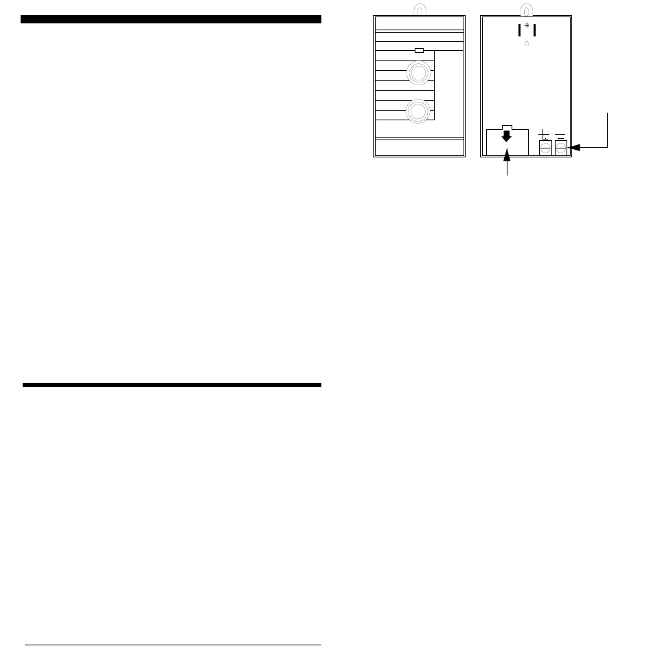
Installing Line Carrier Devices
21
Installing Line Carrier Devices
This section describes how to install the following
line carrier wireless devices:
• Wireless Interior Siren (WIS)
• X-10 Lamp Module
Notes
The Class II Line Carrier Power Transformer (60-678) is re-
quired for line carrier device operation.
The operation of the lamp module is for supplementary pur-
poses only.
Installing and Programming
the Wireless Interior Siren
(WIS)
Installing and programming the Wireless Interior Si-
ren (WIS) includes the following:
• Setting the WIS DIP switches and installing the
battery
• Connecting an external siren to the WIS
• Programming the WIS house code
Setting the WIS DIP Switches
and Installing the Battery
A 9V backup battery (not included) powers the WIS
during an AC power failure. The battery type can be
alkaline, lithium, or NiCd. When backup battery volt-
age gets low, the WIS sounds a single beep every 60
seconds until the battery is replaced.
To set DIP switches and install the backup batter-
ies:
1. Remove the battery cover on the back of the WIS
as shown in figure 61.
Figure 6 WIS Battery Cover Location
2. Set DIP switches as appropriate (see below).
DIP Switch 1—Battery Type
• OFF—Install an alkaline or lithium type battery.
• ON—Activates a trickle charge circuit for use
with a NiCd battery.
WARNING!
Never turn on DIP switch 1 when using an alkaline or
lithium battery. Personal injury and equipment damage
may result if these batteries are recharged, short-cir-
cuited, punctured, or discharged at higher than accept-
able rates.
DIP Switch 2—External Siren Delay
• OFF—External siren terminals activate immedi-
ately during an alarm condition.
Use this setting when the siren connected to the
external siren terminals is located inside the pre-
mises.
• ON—External siren terminals activate 15 sec-
onds after an alarm condition occurs.
Use this setting when the siren connected to the
external siren terminals is located outside. This
helps prevent disturbing neighbors in cases of ac-
cidental alarms that last fewer than 15 seconds.
DIP Switches 3 and 4—Status Tones
• 3 and 4 OFF—The WIS internal piezos and
external siren do not produce any status tones.
Use this setting when the WIS is installed in or
near sleeping areas.
• 3 ON, 4 OFF—The WIS internal piezos produce
normal-volume status tones.
Use this setting when the WIS is installed in areas
where status tones need to be heard.
BATTERY COMPARTMENT
(DIP SWITCHES INSIDE)
TERMINALS
FOR WIRING
OPTIONAL
HARDWIRE
EXTERIOR
SIREN
(13-046)
8557G21A.DS4
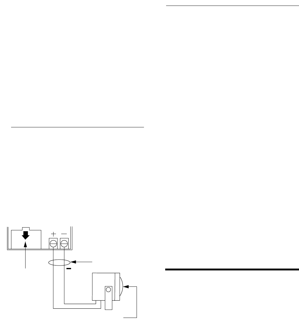
Installing Line Carrier Devices
22
• 3 OFF, 4 ON—The WIS internal piezos and
external siren produce high-volume status tones.
Use this setting when status tones need to be
heard in remote areas, inside and outside of the
premises.
Caution
Never turn on both DIP switches 3 and 4; doing so may per-
manently damage the WIS.
3. Connect the battery to the battery clip and insert
the battery into the compartment.
4. Replace the battery cover.
Connecting an External Siren
to the WIS
Figure 7 shows how to connect the Hardwire Exterior
Siren (13-046) to the WIS terminals. These terminals
activate for alarms only and provide 100 mA maxi-
mum current at 6 VDC.
Caution
Only the Hardwire Exterior Siren (13-046) can be connected
to the WIS terminals. Other sirens may draw more current
than the WIS can provide and can cause permanent dam-
age to the WIS.
Figure 7 Wiring the Hardwire Exterior Siren to the
WIS
Programming the WIS House
Code
1. Plug the WIS into an outlet that is not controlled
by a switch.
2. Press CODE + 1 on the alphanumeric touchpad.
3. The WIS sounds one beep and the WIS LED
flashes, indicating the WIS received the signal
from the panel.
Note
If WIS DIP switches 3 and 4 are set to OFF, no beep will be
heard. You must cause an alarm for the WIS to sound.
4. If the WIS does not respond, unplug it and dis-
connect the battery. Wait at least 30 seconds, and
then reconnect the battery and repeat steps 1 and
2. If the WIS still does not respond, proceed to
appendix B, “Troubleshooting.”
5. To permanently mount the WIS, unplug it and
remove the outlet cover screw.
6. Plug the WIS into the outlet and secure it with
the outlet screw.
WARNING!
Use extreme caution when securing the WIS to a metal
outlet cover. You could receive a serious shock if the
metal outlet cover drops down onto the prongs of the
plug while you are securing the WIS and cover to the
outlet box.
Installing X-10 Lamp Modules
When installing X-10 Lamp Modules:
• Use only incandescent lamps.
• Do not plug X-10 Lamp Modules into outlets con-
trolled by a switch.
• Do not use extension cords to connect several
lamps to one module.
Caution
Use X-10
Lamp
Modules to control light fixtures. Do not use
X-10
Appliance
Modules. Appliance Modules are not con-
trolled during an alarm.
OBSERVE
POLARITY
BATTERY
COMPARTMENT
(DIP SWITCHES
INSIDE)
HARDWIRE EXTERIOR SIREN (13-046)
100 mA MAXIMUM DRAW
+
8557G23A.DS4

Testing the System
23
To install X-10 Lamp Modules:
1. Plug the lamp cord into the bottom of the lamp
module.
2. Plug the module into a lower AC outlet.
3. Refer to table D.5 in appendix D for the house
code you programmed into the panel, and then
find the letter that corresponds to that house code
from table C.3 in appendix C. Each letter setting
represents 16 possible panel house codes. For
example, house code 113 corresponds with “B”
on the X-10 Lamp Module’s house dial.
4. Set the house dial on the module to the appropri-
ate letter.
5. Set the unit number dial from 1 to 9 as shown in
table C.4 in appendix C.
Note
X-10 Lamp Module unit numbers 1 and 2 have special sys-
tem functions: unit 1 provides entry and exit lighting, and
unit 2 provides visual indication of arming level. X-10 Appli-
ance Modules assigned to units 3–9 can be individually con-
trolled from the touchpad and are automatically turned off
during police alarms.
Testing the System
This section describes how to perform the following
test procedures:
• Testing sensors
• Testing the Energy Saver Module
• Testing the Hardwire Input Module
• Testing the X-10 Lamp Modules
• Testing phone communication
• Testing central station communications
You should test the system after installing, after ser-
vicing, and after adding or removing devices from the
system. Refer to the troubleshooting chart in appendix
B for troubleshooting help.
Testing Sensors
We recommend that you test the sensors after all pro-
gramming is completed and whenever a sensor-relat-
ed problem occurs.
Note
While the sensor test is a valuable installation and service
tool, it only tests sensor operation for the current conditions.
You should perform a sensor test after any change in envi-
ronment, equipment, or programming.
1. Set the panel PROGRAM/RUN switch to RUN
(up) and attach, close, and secure the panel cover.
2. Place all sensors in their secured (nonalarm)
state.
3. Enter ACCESS CODE + STATUS + 9 (dealer
sensor test) at an alphanumeric touchpad.
4. The speaker announces “Sensor test is on,” inte-
rior sirens and speakers sound one long beep, and
the display reads 9 - SENSOR TEST.
5. Trip each sensor one at a time.
6. Interior sirens and speakers sound transmission
beeps as each sensor is tripped. Each beep repre-
sents one data round.
7. Count the number of transmission beeps and
refer to table 3 for minimum requirements.
8. After the beeps, [sensor #] OK is displayed con-
firming the sensor number tested. If the system
does not respond, or if the sensor does not meet
the minimum transmission beep requirements,
refer to the “If a Sensor Fails the Sensor Test”
section.
9. Press the STATUS button when you think all
sensors are tested. The system announces any
untested sensor numbers.
If all sensors have been tested, the alphanumeric
touchpad displays ALL SENSOR OKAY and the
speaker announces “Sensor test is on. All sensor
test okay.”
10. Test all untested sensors. The system stays in
sensor test for 15 minutes, preserving the list of
untested sensors. After 15 minutes the panel dis-
arms to level 1, automatically.
11. Enter ACCESS CODE + STATUS + 9 while
the system is still in sensor test if you need more
time to complete the sensor test.
12. Enter ACCESS CODE + 1 to exit sensor test.
13. The system disarms to level 1, and the speaker
announces “Alarm system is off.”
Note
While in dealer sensor test, a sensor will not beep unless
there is at least 10 dB of wireless signal margin.

Testing the System
24
If a Sensor Fails the Sensor
Test
If sirens do not beep when a sensor is tripped, use an
ITI RF Sniffer (60-401) test tool to verify that the sen-
sor is transmitting. Constant beeps from the RF Sniff-
er indicate a runaway (faulty) sensor. Remove the
sensor’s battery and replace the sensor.
If possible, locate sensors within 100 feet of the panel.
While a transmitter may have a range of 1,000 feet or
more out in the open, the environment at the installa-
tion site can have a significant effect on transmitter
range. Sometimes a change in sensor location can
help overcome adverse wireless conditions.
To improve sensor communication, you can
• reposition the sensor,
• relocate the sensor,
• if necessary, replace the sensor.
To reposition a sensor:
1. Rotate the sensor and test for improved sensor
communication at 90 and 180 degrees from the
original position.
2. If poor communication persists, relocate the sen-
sor as described as follows.
To relocate a sensor:
1. Test the sensor a few inches from the original
position.
2. Increase the distance from the original position
and retest until an acceptable location is found.
3. Mount the sensor in the new location.
4. If no location is acceptable, replace the sensor.
To replace a sensor:
1. Test a known good sensor at the same location.
2. If the transmission beeps remain below the mini-
mum level, avoid mounting a sensor at that loca-
tion.
3. If the replacement sensor functions, contact ITI
for repair or replacement of the problem sensor.
Testing the Energy Saver
Module (ESM)
Note
Upper sensor number 88 must be on to enable the Energy
Saver Module.
To test the Energy Saver Module:
1. Press STATUS + STATUS to display the sys-
tem status, ENERGY SAVER OFF, and the
present TEMPERATURE ##. The temperature
displayed (and/or announced) should match the
house thermostat. If the temperatures do not
match, refer to “Programming the Energy Saver
Module Freeze and Set Temperatures” section or
the “Troubleshooting” table in appendix B.
2. Press COMMAND + 5 to turn the energy saver
function on. The display will indicate ENERGY
SAVER ON and the ESM relay will click once.
3. Press COMMAND + 5 again to turn the energy
saver function off. The display will indicate
ENERGY SAVER OFF.
Note
There is a 5-minute delay after the Energy Saver Module re-
turns control to the furnace/AC before it will override the fur-
nace/AC again.
If the red ESM LED is not flashing continuously, set the pan-
el PROGRAM/RUN switch to RUN and turn off the panel
power switch. Verify that all wiring is correct and that all bus
devices (including hardwire touchpads) are set with differ-
ent unit numbers.
Whenever the ESM unit number is changed, you must turn
off the panel power switch, turn it back on, and then enter
the program mode for the panel and ESM to communicate
successfully.
Table 4 Minimum Transmission Beeps
Type of Sensor Number of
Beeps
Wireless Intrusion Sensors 7–8 beeps
Wireless Smoke & Heat Sensors 7–8 beeps
Wireless Environmental/Panic Buttons 7–8 beeps
Hardwire Loops 1
Panel Emergency Buttons 1

Testing the System
25
Testing the Hardwire Input
Module (HIM)
To test the optional Hardwire Input Module:
1. Verify that all wiring at the panel and the HIM
are correct.
2. Turn on the panel power switch.
Note
If the red HIM LED is not flashing continuously, set the panel
PROGRAM/RUN switch to RUN and turn off the panel pow-
er switch. Verify that all wiring is correct and that all bus de-
vices (including hardwire touchpads) are set with different
unit ID numbers.
Whenever the HIM unit ID number is changed, you must
turn off the panel power switch, turn it back on, and then en-
ter the program mode for the panel and HIM to communi-
cate successfully.
If the system uses hardwire sensors only, turn off upper
sensor 94 (Receiver Failure) in the panel.
3. Set the panel’s PROGRAM/RUN switch to
PROGRAM.
If the alphanumeric display continues to read 1-
OFF and the 1 is flashing, you must enter the in-
stall code (four digit install access code) to get the
panel into the program mode.
The alphanumeric display should read PRO-
GRAM MODE and the red HIM LED should be
flashing continuously, indicating successful bus
communication with the panel.
4. Set the panel’s PROGRAM/RUN switch to RUN
and refer to the “Testing Sensors” section for
testing hardwired sensors connected to the HIM.
Testing the Hardwire Output
Module (HOM)
To test the optional Hardwire Output Module:
1. Verify that all wiring at the panel and the HOM is
correct.
2. Turn on the panel power switch.
3. Set the panel’s PROGRAM/RUN switch to
PROGRAM.
If the alphanumeric display continues to read 1-
OFF and the 1 is flashing, you must enter the in-
stall code (four digit install access code) to get the
panel into the program mode.
The alphanumeric display should read PRO-
GRAM MODE and the red HOM LED should be
flashing continuously, indicating successful bus
communication with the panel.
4. Set the panel’s PROGRAM/RUN switch to
RUN.
5. Activate each of the programmed system trigger-
ing events to verify correct HOM output
response.
Note
If the red HOM LED is not flashing continuously, set the
panel PROGRAM/RUN switch to RUN and turn off the pan-
el power switch. Verify that all wiring is correct and that all
bus devices (including hardwire touchpads) are set with dif-
ferent unit ID numbers.
Whenever the HOM unit ID number is changed, you must
turn off the panel power switch, turn it back on, and then en-
ter the program mode for the panel and HOM to communi-
cate successfully.
Testing the X-10 Lamp
Modules
Refer to table C.4 in appendix C for X-10 lamp and
appliance module control operation.
To test the X-10 Lamp Modules:
1. Press COMMAND + 0 repeatedly to turn all
lights on and off together. Appliance modules, if
any, are all turned off by pressing COMMAND
+ 0 but are not all turned on this way.
2. Press BYPASS + 1 repeatedly to turn light 1 on
and off.
3. Repeat step 2 for remaining assigned lamp and
appliance module unit numbers.
4. Press ACCESS CODE + 3 to arm the system to
Level 3-Away. Unit 1 light should turn on and
stay on for 5 minutes. Unit 2 light should blink
three times to indicate the arming level. All
remaining lights should be unaffected.
5. Press ACCESS CODE + 1 to disarm the system.
If Unit 1 light was on for an entry or alarm, it

Testing the System
26
will turn off in 5 minutes. Unit 2 light should
blink once to indicate arming Level 1-Off. All
remaining lights should be unaffected.
6. Lights should turn on and remain on during fire
and auxiliary/medical alarms and flash during a
police or an intrusion alarm.
Testing Phone Communication
Perform a phone test to check the phone communica-
tion between the panel and the central station.
To perform a phone test:
1. Enter ACCESS CODE + 8 at an alphanumeric
touchpad.
2. The display reads 8 - PHONE TEST, the panel
speaker and all interior sirens sound one long
beep, and the speaker announces Phone test is
on.
3. When the panel completes the test, the system
returns to level 1 and the speaker announces
Phone Test is OK. Alarm system is OFF.
4. If the panel announces Phone test failure, pro-
ceed to the following instructions.
If the phone test fails:
1. Check that the panel is plugged into the RJ-31X/
CA-38A phone jack.
2. Enter ACCESS CODE + 8 again.
3. If the phone test fails again, check the phone
number programmed into the panel.
4. If the phone test fails again, check the phone con-
nection wiring.
Testing Central Station
Communication
After performing sensor and phone tests, check that
the system is reporting alarms successfully to the cen-
tral station.
To test communication with the central station:
1. Call the central station and tell the operator that
you will be testing the system.
2. Arm the system.
3. Test each of the touchpad and wireless panic but-
tons and trip at least one sensor of each type—
fire, intrusion, etc.—to verify that the appropriate
alarms are working correctly.
4. If an Audio Verification Module is installed, ver-
ify that it is operating correctly and that the cen-
tral station can both listen-in and talk-back
through it.
5. When you finish testing the system, call the cen-
tral station to verify that the alarms were
received.
Note
If you experience trouble communicating with the central
station (or Downloader), verify the panel’s primary phone
number and also that panel feature number F33 (Download-
er Access Enable) is turned on. Also verify panel feature
number F43 (Demo Kit Mode) is turned off (default setting).
If F43 is on, the account number defaults to “UD-EMO” to let
the central station know that the panel is in the demo kit
mode of operation and that special demo defaults and spe-
cial alarm handling is in force.
Displaying the Panel
Version Code
After testing and troubleshooting the system (as out-
lined in this section and in appendix B) you may re-
quire Technical Support assistance. To precisely
identify the panel hardware and software to support
personnel, you can display the panel hardware/soft-
ware version code.
To display/announce the panel version code:
1. Set the panel RUN/PROGRAM switch to RUN.
2. Enter primary ACCESS CODE + STATUS + 7.
The alphanumeric touchpad will display
YYY*XXX and System YYY Level XXXX will be
announced. YYY represents the panel family
(hardware) product code and XXXX represents
the EEPROM (software) version code.

Appendix A: Command Summary
27
Appendix A: Command Summary
This appendix contains a summary of all system user commands and what each command does. For operating
command details refer to the Security and Home Automation Owner’s Manual.
User Operating Command Summary
Table A.1 provides a description of all commands for operating the system. For commands that require an access
code, use either the primary or secondary access code unless otherwise indicated. While these are called user
operating commands, you may need to use some or all of these commands during the installation and program-
ming process. In the table, CODE represents the four-digit access code (default is 1234).
Table A.1 Summary of User Operating Commands
Action Command Short Command Voice Message Confirmation
Disarm to level 1-Off CODE + 1 Alarm system is off.
Arm to level 2-Stay CODE + 2 COMMAND + 2 *Alarm system is on, level 2.
Arm to level 2, no
delay CODE + 2 + 4 COMMAND + 2 + 4 *Alarm system is on, level 2, no delay.
Arm to level 2, indi-
rect bypass CODE + 2 + BYPASS Alarm system is on, level 2. Sensor
[sensor #] bypassed.
Arm to level 3-Away CODE + 3 COMMAND + 3 *Alarm system is on, level 3.
Arm to level 3, no
delay CODE + 3 + 4 COMMAND + 3 + 4 *Alarm system is on, level 3, no delay.
Arm to level 3, indi-
rect bypass CODE + 3 + BYPASS Alarm system is on, level 3. Sensor
[sensor #] bypassed.
Direct bypass †CODE + BYPASS + [sensor #] Sensor [sensor #] bypassed.
Unbypass ‡ CODE + BYPASS + [sensor #] Sensor [sensor #] okay.
Energy Saver Mod-
ule on/off CODE + 5 COMMAND + 5 Energy Saver is on/off.
Chime on/off CODE + 7 COMMAND + 7On, off.
Phone test on CODE + 8 Phone test is on.
Sensor test on CODE + 9 Sensor test is on.
All lights on/off CODE + 0 COMMAND + 0On, off.
Individual lights on/
off BYPASS + n (n= 1-9) [Unit #] on/off.
Review alarm mem-
ory CODE + STATUS + 5 COMMAND +
STATUS Alarm memory is okay, or
Sensor [sensor #] [alarm name]
alarm memory.
Review short panel
status STATUS Alarm system is [status message].
(continued)

Appendix A: Command Summary
28
System Settings (User-Programming) Command Summary
Table A.1 provides a description of all user-programming commands. For commands that require an access code
(CODE), use the primary access code (default is 1234).
To enter the user-programming mode, press CODE + STATUS + 8. The system will announce System memory
open. Press BYPASS or STATUS buttons to scroll through the list of system settings. Proceed to any of the
desired actions listed in table D.6.
To exit user-progamming mode at any time, press BYPASS + 99 + COMMAND + COMMAND. Or, wait 1
minute—system will automatically announce Good-bye and return to the normal mode of operation..
Review long panel
status CODE + STATUS + 1 STATUS + STATUS Hello alarm system is... (see Owner’s
Manual for possible messages)...Good-
bye.
Panel Version CODE + STATUS + 7
System yyy
(product code)
Level xxxx
(EEPROM code)
Adjust alphanumeric
display brightness Press and hold buttons 1–4
(1–full dim, 4–full bright)
* Feature number F37 (Quick Arming) must be on to enable short arming commands. This short command only works
when arming to a higher level.
† This command only works if the sensor you are bypassing is active in the current security level.
‡ This command only works when upper sensor 87 is off and you are unbypassing a sensor that is already bypassed.
Table A.2 Summary of System Settings (User-Programming) Commands
Action Command Display/Voice Message Confirmation
Enter new primary
access code 00 00 + COMMAND + COMMAND
+ [new CODE] + COMMAND [new primary access code], okay.
Enter new secondary
access code (01-04) [01–04] + COMMAND + COM-
MAND + [new CODE] + COM-
MAND
[new secondary access code], okay.
Enter new arm/dis-
arm code 05–23 [05–23] + COMMAND + COM-
MAND + [new CODE] + COM-
MAND
[new arm/disarm access code], okay.
Enter new Energy
Saver Module low
temperature setting
53 + COMMAND + COMMAND
+ [new low temp.] + COMMAND [new ESM low temperature], okay.
Enter new Energy
Saver Module high
temperature setting
54 + COMMAND + COMMAND
+ [new high temp.] + COM-
MAND
[new ESM high temperature], okay.
Turn quiet exit on or
off 77 + COMMAND + COMMAND [On or off]
Turn download
enable on or off 88 + COMMAND + COMMAND [On or off]
Table A.1 Summary of User Operating Commands (Continued)
Action Command Short Command Voice Message Confirmation

Appendix B: Troubleshooting
29
Appendix B: Troubleshooting
This appendix contains a summary of system troubleshooting suggestions.
Table B.1 Troubleshooting System Problems
Feature Problem Solution
Access Code
Customer cannot remember access code(s).
1. Check your records to see if you have the customer’s access
code(s) on file.
2. If panel is monitored, trap the panel and read the access code(s)
from the CS-4000 or read the access code(s) from the Downloader.
3. If panel is not monitored, clear memory and reprogram the panel
locally.
Installer cannot remember install code.
1. Check your records to see if you have the install code on file.
2. If panel is monitored, trap the panel and read the access code(s)
from the CS-4000 or read the access code(s) from the downloader.
3. If the panel is not monitored and has no access to downloading,
clear memory and reprogram the panel locally.
Some access codes do “strange things.”
1. Codes containing the number 6 are reserved. 6 is used for phone
sensor bypassing.
2. Codes 7777, 8888, and 9999 are reserved for phone panic alarms.
3. Access code’s last two digits must not be the same for correct
duress code operation. (See duress code feature in this table.)
Arming/Disarming
System won’t arm.
1. If arming to level 2, make sure all monitored perimeter doors and
windows are closed.
2. If arming to level 3, make sure all perimeter and interior sensors are
closed.
3. Press STATUS for an indication of the problem.
Batteries
Touchpad indicates
CPU low battery
and/or
System battery failure
is heard.
Check the panel backup battery and connections and replace if nec-
essary. Also, refer to the panel power LED section in this table.
Touchpad indicates
[sensor #] trouble
and/or
Sensor [sensor #] low battery
is heard.
Replace the indicated sensor’s battery.

Appendix B: Troubleshooting
30
Bypass
Touchpad indicates
Fail
and/or
Invalid
is heard when you attempt to bypass a sensor.
Sensor may already be bypassed or you are trying to bypass a 24-
hour sensor that cannot be bypassed or a sensor that is not active in
the current security level.
System cancels sensor bypass when you try to arm to level 2 or 3.
Arm to the desired level before bypassing a sensor.
Central Station Reporting
Central station is not receiving reports from panel.
1. Check that the DB-8 Cord is plugged into the panel phone jack and
into the RJ-31X/CA-38A Jack.
2. Check for proper RJ-31X/CA-38A Jack to phone line wiring.
3. Verify with the central station operator that the correct receiver line
phone number is programmed into the panel. Reprogram the phone
number and retest, if necessary.
4 Verify that the correct phone format (ITI or 4/2) is being used.
5. Replace faulty RJ-31X/CA-38A Jack.
6. Replace faulty DB-8 Cord.
7. Check that the premises phone line is working.
8. Perform a phone test.
Duress Code
Optional duress code is not working.
1. Make sure last two digits of access code are not the same. (See
access code feature in this table.)
2. Check that upper sensor 86 (duress alarm) is on.
False Alarm
Alarm is being sent by mistake.
Enter ACCESS CODE + 1 immediately to cancel the alarm. This com-
mand bypasses the alarm if done within 15 seconds after activation
(feature number F06 [Dialer Abort] must be on). The system will
announce alarm bypassed and report will not be sent to the monitor-
ing station.
Note
Fire alarms and duress detections cannot be bypassed.
Hardwire Alphanumeric Touchpad
Touchpad display seems “stuck” in the program mode.
Check that panel PROGRAM/RUN switch is set to RUN (up).
Touchpad displays incorrectly or displays
DA ###
and does not respond to buttons.
1. If panel has been preprogrammed with an install code, enter the
four-digit install code at a working touchpad or from a telephone .
2. Check for hardwire bus address confilct (two devices having the
same device address).
3. Check for out-of-range device address number. Should be 000–
007.
Table B.1 Troubleshooting System Problems (Continued)
Feature Problem Solution

Appendix B: Troubleshooting
31
Hardwire Alphanumeric Touchpad (Continued)
Touchpad displays
**********
’ and does not respond to buttons.
1. Reset the touchpad by switching into and out of program mode.
Switch the panel PROGRAM/RUN switch from RUN to PROGRAM.
Enter the four-digit install code if panel has been preprogrammed with
one using a working touchpad or telephone. Switch the panel PRO-
GRAM/RUN switch back to RUN again.
2. Check for hardwire bus miswiring.
Touchpad appears “dead” (no display or response to buttons).
1. Check that the wiring connector is plugged into the back of the
touchpad.
2. Check for hardwire bus miswiring, opens, or shorts.
3. Check panel fuse F2.
Hardwire Output Module
LED is off (not blinking).
1. Check HOM and panel fuses.
2. Check wiring at HOM and panel.
3. Check that HOM unit number setting is different from all other con-
nected bus devices.
4. Check for proper panel/HOM initialization after changing unit num-
bers.
LED stays on.
1. Reinitialize panel and HOM by turning panel power off and on.
2. HOM circuit failure. Replace HOM.
LED blinks but outputs don’t activate.
1. Check panel/HOM programming.
One output never activates.
1. Check panel/HOM programming.
2. Check that the point (HOM output) programmed trigger event actu-
ally occurs.
3. Check wiring at HOM terminals and connected device.
Output(s) activates only momentarily.
1. Check that the panel/HOM point programming (HOM output) uses
the correct response configuration.
Output(s) activates randomly.
1. Check HOM and panel fuses.
2. Check wiring routing and length between panel and HOM.
3. Check that HOM unit number setting is different from all other con-
nected bus devices.
Hardwire Output Module (Continued)
HOM tamper input is inoperable.
Table B.1 Troubleshooting System Problems (Continued)
Feature Problem Solution

Appendix B: Troubleshooting
32
1. Some panels and panel versions do not “read” the HOM’s built-in
tamper input status. Connect the HOM tamper switch to a panel or
HIM zone input.
One output stays activated.
1. Check to see if the point is programmed for a 3-minute “on” time
and if the triggering event for the point is repeatedly resetting the 3-
minute timer.
2. Output may have failed or been overloaded. Reprogram to use a
different (unused) output.
Hardwire Siren
Exterior sirens are not producing alarm sounds.
1. Check for 12 to 22 VDC between panel terminals 3 and 4 and
for 12 VDC between terminals 4 and 12.
2. Check panel fuses F1 and F2.
3. Check for correct wiring at the siren and panel terminals.
4. Check for required jumper wire between panel terminals 5 and 12.
Exterior sirens produce status sounds.
Check for correct wiring at the siren and panel terminals.
Interior sirens are not producing sounds.
1. Check for 12 VDC between panel terminals 17 and 18 with siren
on.
2. Check panel fuses F1 and F2.
3. Check for correct wiring at the siren and panel terminals.
4. Make sure that F11 (Interior Siren Sounds Disable) feature is off.
Hardwire Zones
Panel does not respond to hardwire zone input.
1. Check that zones are programmed into panel and add if missing.
2. Make sure that zone is in a restoral-required group or make sure
that system is armed to active level before tripping sensor.
3. If optional HIM zone, check that the HIM LED is blinking to show
communication with panel.
Note
Panel hardwire zones are ignored for 1 minute following power-on
(HIM zones are not ignored for this period).
Touchpad indicates
[sensor #], trouble
and/or
Sensor [sensor #], trouble
is heard.
1. Check that the 4.7K ohm end-of-line resistor is correctly installed in
the zone loop circuit.
2. Check normally open (N/O) circuit for a break in the wires.
3. Check normally closed (N/C) circuit for a short in the wires.
Lights
Light fixture using X-10 Lamp Module does not work.
Table B.1 Troubleshooting System Problems (Continued)
Feature Problem Solution

Appendix B: Troubleshooting
33
See X-10 Lamp Modules feature in this table.
Panel
Panel does not power up. Panel LED is off and alphanumeric touchpad display is dark.
1. Check that panel power switch is on.
2. Check the AC circuit breaker to be sure the circuit is live.
3. Check that the backup battery is installed correctly, the battery
wires are connected, and the AC power transformer is plugged in.
4. Check for proper panel and transformer wiring.
5. Measure the incoming AC voltage at the panel terminals. Should
read from 16 to 18.5 VAC at panel terminals 1 and 2.
No incoming AC voltage at panel terminals 1 and 2.
1. Unplug the AC power transformer and disconnect the wires from
the transformer and the panel.
2. Check transfomer to panel wire for short or open circuits.
3. Plug in the transformer and check for 16.5 VAC at the transformer
unconnected terminals. If zero (0) volts, replace the transformer.
Panel power LED is on constantly, display indicates
CPU Low Battery
or voice sounds
Battery failure.
1. Check that the backup battery is installed correctly, the battery
wires are connected, and the AC power transformer is plugged in.
2. Measure the incoming AC voltage at the panel terminals. It should
read from 16 to 18.5 VAC at panel terminals 1 and 2.
3. Remove the backup battery power by disconnecting the battery’s
red (positive) wire.
4. Check for 13.5 to 13.9 VDC battery charging voltage between
panel terminal 4 (GND) and the disconnected battery red wire. If the
charging voltage is not within range, call Technical Services.
5. Check for 11.5 to 13.9 VDC battery voltage between the backup
battery’s spade lugs. If the battery voltage is not within the recom-
mended range, replace the battery.
Note
When the panel is running a backup battery test, the reading at the
connected battery can range from 11.4 to 13.7 VDC. The panel auto-
matically runs a backup battery test under the following conditions:
(1) on initial power-up. (2) during sensor test (not dealer sensor test),
(3) once every minute when backup battery has failed, (4) once every
24 hours, at the programmed STIME.
6. Restore the backup battery power by reconnecting the battery’s red
wire.
Note
While the AC power transformer is plugged in, the panel automatically
charges the battery. While the battery is charging for the first time it is
normal for the system to indicate
System battery failure
. This can
take a number of hours depending on the battery’s initial charge.
Once the battery reaches 12.5 VDC (full charge as measured while in
battery test), the arming level stops flashing. If the trouble condition
persists after 24 hours, replace the backup battery.
Panel (Continued)
Table B.1 Troubleshooting System Problems (Continued)
Feature Problem Solution

Appendix B: Troubleshooting
34
Panel power LED is flashing, and after pressing STATUS the touchpad indicates
AC
power failure
. (Panel continues to operate from backup battery.)
1. Check the AC circuit breaker to be sure the circuit is live.
2. Check for proper panel and transformer wiring.
3. Check that the transformer is plugged into a nonswitched outlet and
secured with the provided screw.
4.Check that the transformer is supplying AC to the panel. (Trans-
former internal fuse may be blown.)
WARNING!
Be careful when securing the transformer to an outlet with a metal
cover. Hold the cover tightly in place. You could receive a serious
shock if the metal outlet cover drops down onto the prongs of the plug
while you are securing the transformer and cover to the outlet box.
Phones
Loss of dial tone on premises phones after wiring the RJ-31X Jack or connecting the
DB-8 Cord.
1. Wait 2 minutes and try again. The panel may be busy trying to
report to the CS-4000.
2. Check the RJ-31X Jack’s wiring.
3. Check the panel connection to the DB-8 Cord.
4. Replace the RJ-31X Jack.
5. Replace the DB-8 Cord.
6. Perform a phone test after troubleshooting the phone line.
Constant dial tone, preventing dial out on premises phones.
Polarity-sensitive phones exist on the premises. Reverse the phone
wires connected to the brown and gray wire terminals on the RJ-31X
Jack.
Phone does not work.
Disconnect the panel DB-8 Cord from the RJ-31 Jack. If the phone
still doesn’t work, the system is okay and the problem is in the wiring.
Sensor
Touchpad indicates
[sensor #] trouble
and/or
Sensor [sensor #] trouble
is heard.
Replace the sensor’s cover, if it is off. Trip the sensor.
Touchpad indicates
[sensor #] supervisory
and/or
Sensor [sensor #] failure
is heard.
The sensor is not communicating with the panel.
Touchpad indicates
Sensor [sensor #] trouble
and/or
Sensor [sensor #] low battery
is
heard.
Replace the indicated sensor’s battery.
Smoke Sensor
Beeps once every minute.
Batteries are low. Replace all of the smoke sensor batteries.
Trouble Beeps (see also
Panel
)
Table B.1 Troubleshooting System Problems (Continued)
Feature Problem Solution

Appendix B: Troubleshooting
35
Press STATUS for an indication of the problem. Doing a status or disarm (level 1) dis-
ables the trouble beeps for 10 hours.
Wireless Interior Siren (WIS)
No sound or LED activity from the siren.
1. Check that the panel AC transformer is plugged into an outlet.
2. Check that the WIS is not plugged into an outlet controlled by a
switch. Relocate to a different outlet, if necessary.
3. Program the house code into the panel and set the WIS DIP
switches.
4. Check that the panel is powered by the special two-wire Class II
Line Carrier Power Transformer.
5. Make sure that the WIS is on the same electrical phase wiring as
the AC power transformer. Relocate the WIS to various outlets to
identify compatible locations.
6. Move the WIS to a circuit that is not used by any other appliances.
Intermittent siren operation.
1. Check that the WIS is not plugged into an outlet controlled by a
switch. Relocate to an unswitched outlet.
2. Move the WIS to a circuit that is not used by any other appliances.
The WIS beeps once every minute.
The WIS may have a low battery. Replace with the appropriate battery
based on the setting of DIP switch 1. (ON = NiCd, OFF = alkaline or
lithium.)
Wireless Sensors
The panel does not respond to sensor activity. There are no alarm, chime, or sensor test
sounds.
1. Check that the wireless sensor battery is installed.
2. Check the sensor battery for low voltage. Replace batteries, if nec-
essary.
3. Use an RF Sniffer (60-401) to verify that sensor is transmitting.
4. Check that the sensor is programmed (learned) into panel memory.
Learn the sensor, if necessary.
5. Verify that both panel antennas are installed and connections tight.
The panel responds intermittently to wireless sensor signals.
1. Rotate the sensor position from 90 to 180 degrees.
2. Mount the sensor in a different location.
3. Verify that both panel antennas are installed and connections tight.
Wireless Touchpads
The panel does not respond to wireless touchpad commands.
1. Operate touchpads from different locations to locate areas of inter-
mittent operation.
2. Check and/or replace wireless touchpad battery.
3. Program or reprogram the touchpad(s) into the panel.
X-10 Lamp Modules
Table B.1 Troubleshooting System Problems (Continued)
Feature Problem Solution

Appendix B: Troubleshooting
36
Light fixtures controlled by the X-10 Lamp Module are not working.
1. Check that the lamp has a working bulb and that the lamps switch
is on.
2. Confirm the lamp’s operation at a working outlet.
3. Check that the lamps are plugged into X-10 Lamp Modules and the
X-10 Lamp Modules are plugged into outlets that are not controlled by
a switch. Relocate to nonswitched outlets, if necessary.
4. Check that the panel is powered by the special two-wire Class II
Line Carrier Power Transformer ((60-678).
5. Check that the HOUSE dial on the X-10 Lamp Module matches the
house code programmed into the panel.
Table B.1 Troubleshooting System Problems (Continued)
Feature Problem Solution

Appendix C: Programming Tables
37
Appendix C: Programming Tables
This appendix contains tables for selecting sensor group numbers and X-10 Lamp and Appliance Module house
and unit codes. Table notes appear at the bottom of the table, on the next page.
Table C.1 Sensor Group Characteristics
No. Name Application Alarm Delay Restoral Supervisory CS
Report Chime Active
Levels
00 Fixed
Panic 24-hour audible fixed emergency but-
tons. Police Instant √ √ 1, 2, 3
01 Portable
Panic 24-hour audible portable emergency
buttons. Police Instant √1, 2, 3
02 Fixed
Panic 24-hour silent fixed emergency buttons. Silent Instant √ √ 1, 2, 3
03 Portable
Panic 24-hour silent portable emergency but-
tons. Silent Instant √1, 2, 3
04 Fixed
Auxiliary 24-hour auxiliary sensor, such as Pen-
dant Panic or holdup button. Auxiliary Instant √ √ 1, 2, 3
05 Fixed
Auxiliary 24-hour auxiliary emergency button.
Siren shutoff confirms CS report. Auxiliary Instant √ √ 1, 2, 3
06 Portable
Auxiliary 24-hour portable auxiliary alert button. Auxiliary Instant √1, 2, 3
07 Portable
Auxiliary 24-hour portable auxiliary button. Siren
shutoff confirms CS report. Auxiliary Instant √1, 2, 3
08 Special
Intrusion Special belongings, such as gun cabi-
nets and wall safes. Police Instant √ √ √ 1, 2, 3
09 Special
Intrusion Special belongings, such as gun cabi-
nets and wall safes. Police Standard √ √ √ 1, 2, 3
10 Entry/Exit
Delay Entry and exit doors that require a stan-
dard delay time. Police Standard √ √ √ √ 2, 3
11 Entry/Exit
Delay Garage doors and entrances that
require an extended delay time. *Police Extended √ √ √ √ 2, 3
12 Entry/Exit
Delay Driveway gates and entrances that
require a twice extended delay time. *Police Twice
Extended √ √ √ √ 2, 3
13 Instant
Perimeter Exterior doors and windows. Police Instant √ √ √ √ 2, 3
14 Instant
Interior Interior doors. Police Follower √ √ √ 2, 3
15 Instant
Interior Interior PIR motion sensors. *Police Follower √ √ 2, 3
16 Instant
Interior Interior doors. Police Follower √ √ √ 3
17 Instant
Interior PIR motion sensors. *Police Follower √ √ 3
18 Instant
Interior PIR motion sensors subject to false
alarms. * †Police Follower √ √ 3
(continued)
19 Delayed
Interior Interior doors that initiate a delay before
going into alarm. *Police Standard √ √ √ 3

Appendix C: Programming Tables
38
20 Delayed
Interior PIR motion sensors that initiate a delay
before going into alarm. *Police Standard √ √ 3
21 Local
Instant
Interior
24-hour local alarm zone protecting
anything that opens and closes. Police Instant √ √ 1, 2, 3
22 Local
Delayed
Interior
Same as group 21, plus activation ini-
tiates a delay before going into alarm. Police Standard √ √ 1, 2, 3
23 Local
Instant
Auxiliary
24-hour local alarm zone protecting
anything that opens and closes. ‡ Auxiliary Instant √ √ 1, 2, 3
24 Local
Instant
Auxiliary
24-hour local alarm zone protecting
anything that opens and closes. Sirens
shut off at restoral. *
Auxiliary Instant √ √ 1, 2, 3
25 Local
Special
Chime
Notify the user when a door is opened.
Sounds emit from a local annunciator. *Special
Chime Instant √1, 2, 3
26 Fire 24-hour fire, rate-of-rise heat, and
smoke sensors. §Fire Instant √ √ √ 1, 2, 3
27 Output
Module Hardwire Output Module (HOM) lamp
control or other customer feature. ‡Silent Instant √ √ 1, 2, 3
28 Output
Module HOM, PIR motion sensor, sound sen-
sor, or pressure mat. ‡Silent Instant √1, 2, 3
29 Auxiliary Freeze sensor. Auxiliary Instant √ √ 1, 2, 3
32 Output
Module HOM, PIR motion sensor, sound sen-
sor, or pressure mat. ‡Silent Instant 1, 2, 3
Note: Check marks (√) represent characteristics present in a group.
* This group is not certified as a primary protection circuit for UL-listed systems and is for supplementary use only.
† Sounds instant police siren if two or more sensors are tripped within 4 minutes. Otherwise sensors are followers to delayed
sensors. If central station feature 15 (Alarm Verification) is on, group 18 functions like group 17.
‡ This group has not been investigated by UL.
§ This group is required for UL-listed residential fire alarm applications.
Table C.1 Sensor Group Characteristics (Continued)
No. Name Application Alarm Delay Restoral Supervisory CS
Report Chime Active
Levels

Appendix C: Programming Tables
39
Table C.2 Sensor Text Numbers
Text No. Text No. Text No. Text No.
Null 00 0 30 Floor 60 Shock 90
A 01 1 31 Freeze 61 Side 91
B 02 2 32 Front 62 Sliding 92
C 03 3 33 Gallery 63 Smoke 93
D 04 4 34 Garage 64 Sound 94
E 05 5 35 Hall 65 South 95
F 06 6 36 Heat 66 Stairs 96
G 07 7 37 Kitchen 67 Top 97
H 08 8 38 Laundry 68 West 98
I09 939 Level69 Window99
J10 Area40 Library70
K 11 Attic 41 Living 71
L 12 Basement 42 Main 72
M 13 Bathroom 43 Master 73
N 14 Bedroom 44 Mat 74
0 15 Bottom 45 Medical 75
P 16 Breezeway 46 Motion 76
Q 17 Cabinet 47 North 77
R 18 Carpet 48 Office 78
S 19 Closet 49 Panic 79
T20 Den50 Patio80
U 21 Desk 51 Police 81
V 22 Dining 52 Pool 82
W 23 Door 53 Porch 83
X24 Drawer54 Rear84
Y 25 East 55 Room 85
Z 26 Entry 56 Safe 86
Space (blank) 27 Family 57 Screen 87
Apostrophe (‘) 28 Fire 58 Second 88
Dash (-) 29 First 59 Sensor 89

Appendix C: Programming Tables
40
Table C.3 X-10 Lamp and Appliance Module House Code Settings
X-10
Codes Corresponding Panel House Codes
A16 32 48 64 80 96 112 128 144 160 176 192 208 224 240
B1* 17 33 49 65 81 97 113 129 145 161 177 193 209 225 241
C2 183450668298114130146162178194210226242
D3 193551678399115131147163179195211227243
E4 20 36 52 68 84 100 116 132 148 164 180 196 212 228 244
F5 21 37 53 69 85 101 117 133 149 165 181 197 213 229 245
G6 22 38 54 70 86 102 118 134 150 166 182 198 214 230 246
H7 23 39 55 71 87 103 119 135 151 167 183 199 215 231 247
I8 24 40 56 72 88 104 120 136 152 168 184 200 216 232 248
J9 25 41 57 73 89 105 121 137 153 169 185 201 217 233 249
K10 26 42 58 74 90 106 122 138 154 170 186 202 218 234 250
L11 27 43 59 75 91 107 123 139 155 171 187 203 219 235 251
M12 28 44 60 76 92 108 124 140 156 172 188 204 220 236 252
N13 29 45 61 77 93 109 125 141 157 173 189 205 221 237 253
O14 30 46 62 78 94 110 126 142 158 174 190 206 222 238 254
P15 31 47 63 79 95 111 127 143 159 175 191 207 223 239 255 †
* Default setting.
† This house code is reserved for demo panels only.

Appendix C: Programming Tables
41
Table C.4 X-10 Lamp and Appliance Module Operation
Condition Lamp Module
Unit No. 1 Lamp Module
Unit No. 2 Lamp Module
Unit Nos. 3–9
Appliance
Module Unit
Nos. 3–9
On Arming to Level 1-Off
(Not if disarming to level 1 after an
alarm–see below)
Unchanged if ini-
tially off
On for 5 more
minutes if initially
on
1 Blink Unchanged Unchanged
On Arming to Level 2-Stay On for 5 minutes 2 Blinks Unchanged Unchanged
On Arming to Level 3-Away On for 5 minutes 3 Blinks Unchanged Unchanged
On Disarming Any Alarm to Level 1 On for 5 minutes 1 Blink On for 5 minutes If on, off after 5
minutes
On Fire Alarm* On† On† On† Unchanged†
On Police Alarm* Flashing† Flashing† Flashing† Off
On Auxilliary Alarm* On† On† On† Unchanged†
After Fire or Auxiliary Alarm Time-
out On† On† On† Unchanged
COMMAND + 0 (All Lights On) On On On Unchanged
COMMAND + 0 (All Lights Off) Off Off Off Off
*Fire alarms have priority over both police and auxiliary alarms. Police alarms have priority over
auxilliary alarms.
†Stays on until manually turned off or until 5 minutes after the system is disarmed to Level 1-Off.

Appendix D: System Planning Worksheets
42
Appendix D: System Planning
Worksheets
Fill in customer information about this installation:
* Not UL listed; not intended for use in UL listed systems.
Table D.1 Wireless Sensors
Part No. Description Qty.
60-362 Learn Mode Door/Window Sensor
60-409 Learn Mode Recessed Door/Win-
dow Sensor
60-499 Learn Mode Slim Line Door/Win-
dow Sensor
60-461* Learn Mode Shock Sensor
60-459* Learn Mode Sound Sensor (ITI)
60-462* Learn Mode Glass Guard Sensor
60-506 Learn Mode System Smoke Sen-
sor
60-460 Rate-of-Rise Heat Sensor
60-589* Manual Fire Pull Sensor
60-504* Learn Mode Freeze Sensor
60-452 Learn Mode Pendant Panic Sensor
60-458 Single Button Panic Sensor
60-457 Dual Button Panic Sensor
60-578 Water-Resistant Panic Sensor
60-348 Handheld Wireless Touchpad
60-453 Wall-Mount Wireless Touchpad
60-511 Learn ModeDS924i PIR Motion
Sensor
60-592 DS926 PIR Ceiling Mount Motion
Sensor
60-582 Learn Mode Sound Sensor
(IntelliSense)
60-645-95 Wireless Smoke Sensor
(System Sensor 2300RFITI)
Customer
________________________________________
_
Address
_________________________________________
_
City
_____________________
State/Zip
_________________
_
Country
__________________
Phone
___________________
_
Table D.2 Hardwire Devices
Part No. Description Qty. mA SubTot.
Hardwire Sensors/Detectors
13-068* Magnetic Contact
3/8” press fit N/A
13-070* Magnetic Contact –
surface mount N/A
13-360 ESL 449AT Smoke/
Heat Detector 15 mA
13-391 Power Supervision
Module 20 mA
79-004* Fire Pull Station N/A
13-028* PIR Motion Detector 10 mA
Hardwire Sirens
60-252 Hardwire Interior
Speaker & Piezo 5 mA
60-278 Hardwire Interior Siren
& Piezo 75 mA
60-483-
01 Slim Line Hardwire
Interior Siren & Piezo 85 mA
13-046 Hardwire Exterior
Siren 145 mA
Miscellaneous Components
60-584 Superbus Hardwire
Input Module (HIM) 18 mA
60-586 Superbus Alphanu-
meric Touchpad 75 mA
60-620 Superbus Energy
Saver Module (ESM) 10 mA
60-661 Superbus 2-Line, LCD
Alphanumeric TP 115 mA
60-662 Superbus 2-Line, V/F
Alphanumeric TP 120 mA
60-677* Interrogator 200 Audio
Verification Module
(AVM)
10 mA
Total power consumption not to exceed: 750 mA
Table D.3 Recommended Superbus Device
Unit Numbers (addresses)
Superbus Device Factory
Default Recom
mened Actual
Setting
First Alpha. Touchpad 1 1
Second Alpha. Touchpad 1 2
Third Alpha. Touchpad 1 3
Fourth Alpha. Touchpad 1 4
Hardwire Output Module
(HOM) 05
Hardwire Input Module (HIM) 0 6
Energy Saver Module (ESM) 0 7

Appendix D: System Planning Worksheets
43
Table D.4 Sensor Groups and Locations
No. Group Type and Location
01
02
03
04
05
06
07
08
09
10
11
12
13
14
15
16
17
18
19
20
21
22
23
24
25
26
27
28
29
30
31
32
33
34
35
36
37
38
39
40
41
42
43
44
45
46
47
48
49
50
51
52
53
54
55
56
57
58
59
60
61
62
63
64
65
66
67
68
69
70
71
72
73
74
75
76
Table D.4 Sensor Groups and Locations
No. Group Type and Location

Appendix D: System Planning Worksheets
44
Table D.5 Panel Configuration Settings
Feature Choices Default Setting
Primary Phone
Number 2 to 18 digits,
incl. pauses –
Phone Format - ITI
- 4/2, 1400Hz†
- 4/2, 2300Hz†
ITI
Siren Time-out 01–30 min. 4 min.
Install Code 0001–9998 or
****(blank) ****
Account Number 00000–99999 00–000
Entry Delay 008–120 sec. 32 sec.
Extended Delay 01–08 min. 4 min.
Exit Delay 008–184 sec. 32 sec.
Activity Time-out 01–24 hr. 24 hr.
House Code 001–254 001
Freeze Temp (ESM) 40–90° F 42° F
Set Temp (ESM) 32–99° F –
Touchpad Options:
Unit Number 000–007 1
Touchpad Quiet Y or N N
Key Beeps Y or N Y
AVM Mode 01–03, 09–
11† 03
AVM Time-out 030–300 sec. 90 sec.
AVM Code 0001–9998* or
****(blank) ****
HOM Setup ‡
Time Zone 05 (Eastern)
06 (Central)
07 (Mountain)
08 (Pacific)
10 (Hawaii)
05
* Any four digit sequence different than primary, install,
secondary, or arm-disarm access codes, 7777, 8888,
9999, or any number of 6s. Last two digits cannot be the
same.
† If the Phone Format is set to 4/2 1400 or 2300Hz for-
mat, upper sensor 98—Events Report must be off.
If the AVM Mode is set to instant modes 3 or 11 and the
Phone Format is set for 4/2 1400 or 2300Hz format, the
central station must be set with the panel’s account num-
ber in the ATRAP (audio trap) table. The panel will not
hang up the phone when the report is complete, but will
remain on the line for the AVM Time-out duration.
‡ For HOM setup refer to the Hardwire Output Module
(HOM) Installation Instructions document 466-1032,
included with each HOM.
Table D.6 HOM Configuration Settings
Unit
No. Output Point Configuration Number
0101
202
303
404
1105
206
307
408
2109
210
311
412
3113
214
315
416
4117
218
319
420
5121
222
323
424
6125
226
327
428
7129
230
331
432

Appendix D: System Planning Worksheets
45
Table D.7 System Settings
NO. Feature Choices Setting
System Setting (default)
00 Arm Code
(Primary) 0001–9998
(Default: 1234)
01 Arm Code
(Secondary) 0001–9998 or
****(blank)
02 Arm Code
(Secondary) 0001–9998 or
****(blank)
03 Arm Code
(Secondary) 0001–9998 or
****(blank)
04 Arm Code
(Secondary) 0001–9998 or
****(blank)
05 Arm Code
(Arm-Disarm) 0001–9998 or
****(blank)
06 Arm Code
(Arm-Disarm) 0001–9998 or
****(blank)
07 Arm Code
(Arm-Disarm) 0001–9998 or
****(blank)
08 Arm Code
(Arm-Disarm) 0001–9998 or
****(blank)
09 Arm Code
(Arm-Disarm) 0001–9998 or
****(blank)
10 Arm Code
(Arm-Disarm) 0001–9998 or
****(blank)
11 Arm Code
(Arm-Disarm) 0001–9998 or
****(blank)
12 Arm Code
(Arm-Disarm) 0001–9998 or
****(blank)
13 Arm Code
(Arm-Disarm) 0001–9998 or
****(blank)
14 Arm Code
(Arm-Disarm) 0001–9998 or
****(blank)
15 Arm Code
(Arm-Disarm) 0001–9998 or
****(blank)
16 Arm Code
(Arm-Disarm) 0001–9998 or
****(blank)
17 Arm Code
(Arm-Disarm) 0001–9998 or
****(blank)
18 Arm Code
(Arm-Disarm) 0001–9998 or
****(blank)
19 Arm Code
(Arm-Disarm) 0001–9998 or
****(blank)
20 Arm Code
(Arm-Disarm) 0001–9998 or
****(blank)
21 Arm Code
(Arm-Disarm) 0001–9998 or
****(blank)
22 Arm Code
(Arm-Disarm) 0001–9998 or
****(blank)
23 Arm Code
(Arm-Disarm) 0001–9998 or
****(blank)
53 ES Low (ESM) 45-89° F (50°)
54 ES High (ESM) 46-90° F (90°)
77 Quiet Exit ON or (OFF)
88 Download
Enable ON or (OFF)
Notes:
1. 6s should not be used in any part of an access code,
since such a code interferes with bypassing sensors
from a touch-tone phone.
2. Access codes cannot be programmed as 7777, 8888,
or 9999 since these codes are reserved for fire, police,
and auxiliary panics from a touch-tone phone.
3. Each access code whether primary, secondary, arm-
disarm, or AVM must be unique. No two codes can be
the same.
4. 4s or 0s should not be programmed as the first digit in
an access code, since this can interfere with system
disarming.
5. The last two digits of an access code cannot be the
same.
Table D.7 System Settings (Continued)
NO. Feature Choices Setting

Appendix D: System Planning Worksheets
46
Table D.8 Upper Sensor Numbers
No. Sensor Name Description Default Setting
77 Touchpad Tamper Reports a touchpad tamper to the Central Station (CS) if 40 digits are
entered without a valid access code. OFF
78 Freeze Sensor On will activate and report a Freeze Alarm when the room temperature
reaches the programmed freeze temperature. When on, and no tempera-
ture data is received from the Energy Saver Module (ESM), a 78 TROUBLE
alarm is reported.
OFF
79 No Activity When on, if no activity is detected on the premises within the programmed
Activity Time-out, the auxiliary siren will sound. The panel reports to the CS
if the alarm is not canceled within 5 minutes.
OFF
80 Touchpad Fire
Panic On enables the FIRE button on all touchpads (and telephones if F35 is on). ON
81 Touchpad Police
Panic ON enables the POLICE button on all touchpads (and telephones if F35 is
on). ON
82 Touchpad Auxiliary
Panic On enables the AUXILIARY button on all touchpads (and telephones if F35
is on). ON
83 Manual Phone
Test Allows the user to instruct the system to dial CS and report a phone test. ON
84 Opening Report Reports to the CS when the user disarms the system. OFF
85 Closing Report Reports to the CS when the user arms the system. OFF
86 Duress Alarm Reports a silent POLICE EMERGENCY to the CS. OFF
87 Force Armed Reports a FORCE ARMED when user directly or indirectly bypasses any
sensor. Security level and bypassed sensor are reported. (Auto Force
Armed is always reported.)
OFF
88 Energy Saver
Enable When on, the Energy Saver Module (ESM) is able to override the con-
nected thermostat. When on and no temperature data is received from the
ESM, an 88 TROUBLE alarm is reported.
OFF
89 Wireless Touch-
pad Supervisory
or Low Battery
When on, the panel checks for and reports supervisory conditions on Wall
Mount Wireless touchpads. Reports a SUPERVISORY alarm to the alpha-
numeric touchpad if the panel doesn't hear from each touchpad within the
set time (SUPSYNC). If on, the panel will report a touchpad low battery
when any touchpad has a low battery condition.
OFF
90 AC Power Failure If on, reports an AC FAILURE to the CS if the panel has been without AC
power for 15 minutes. OFF
91 Low Panel Battery If on, reports LOW CPU BATTERY to the CS if the panel's back-up battery
voltage drops below 11.4 VDC. ON
92 Panel Tamper If on and armed to level 2 or 3, changing from run to program will activate
and report a CPU TAMPER alarm. ON
93 Automatic Phone
Test If on, the panel reports to the CS at a programmed interval (from daily to
every 255 days). OFF
94 Receiver Failure If on, the panel reports to the CS if the panel does not hear from any wire-
less transmitter for 2 hours. Trouble beeps alert user of the problem. ON
95 Panel Back In
Service When on, the panel reports to the CS at power-up and if a panel reset
occurs. ON
96 Phone Failure If the panel is unsuccessful reporting to the CS after the third of eight
attempts, the panel activates a FAIL TO COMMUNICATE alarm. It contin-
ues to dial the remaining five attempts.
ON
98 Events Report If on (and panel is set up for ITI phone format), the panel automatically
reports to the CS when 28 events are accumulated in the event buffer. If off,
the panel doesn’t report but still accumulates events in the buffer.
Note: Must be off if panel is set up for 4/2 Phone Format.
OFF

Appendix D: System Planning Worksheets
47
.
Table D.9 Feature Numbers
No. Feature Name Description Default Setting
F00 Remote Phone Access On enables, off disables remote phone access. Works in conjunction
with feature F01 below. Off-premises accessing must be done with
primary access code.
ON
F01 Ring Twice–Hang-up–
Ring–Answer On = call premises and let phone ring twice, hang-up and wait 10 sec-
onds, call back premises and panel answers after first ring.
Off = call premises and wait for panel to answer (about 12 rings).
ON
F02 Exterior Siren Delay On = exterior siren activation is delayed 15 seconds.
Off = exterior siren activation is immediate. ON
F03 Toll Saver Determines on which ring the panel answers an alarm or trouble situ-
ation. On = 8 rings, Off = 12 rings. ON
F04 Low Battery Reports On = sensor low-battery conditions are reported weekly.
Off = sensor low-battery conditions are reported daily. ON
F05 Sensor Supervisory
Reports Determines uncorrected supervisory trouble conditions to re-report
daily (off) or weekly (on). ON
F06 Dialer Abort Determines if the phone dialer aborts calls canceled by the owner
before panel dialing is completed. ON
F07 Access Key Type On = ‚ phone key accesses the panel.
Off = ƒ phone key accesses the panel. OFF
F11 Interior Siren Sounds
Disable On = Interior sirens sound alarms only.
Off = Interior sirens sound alarms and status. OFF
F12 Alarm Restoral Reports On = sensor/zone alarm restorals are reported to the CS.
Off = sensor/zone alarm restorals are not reported to the CS. OFF
F13 Low Battery Restoral
Reports On = sensor battery restorals are reported to the CS.
Off = sensor battery restorals are not reported to the CS. OFF
F14 Hourly Phone Test On enables and off disables the hourly phone line voltage test. OFF
F15 Alarm Verification On = panel reports alarm to CS only if two different sensors (in
groups 10–20) are tripped within 4 minutes.
Off = panel reports alarms to CS without second sensor trip.
OFF
F16 Trouble Beeps Disable On = no trouble beeps and panel protests open sensors only.
Off = trouble beeps sound for sensor low-batterty/supervisory condi-
tions and panel protests upon arming when these conditions exist.
Must be off for UL-investigated systems.
OFF
F17 24-Hour Sensor
Tamper Alarm On = sensor tamper alarms are generated in any protection level.
Off = sensor tamper alarms are generated only if the system is armed
to a level where the sensor is active.
OFF
F20 Audio Verification Mod-
ule (AVM) Enable On enables and off disables 2-way voice communication with the
Central Station during an alarm. OFF
F21 Immediate Trouble
Beeps On = trouble beeps sound immediately when a supervisory condition
is detected. Must be on for UL-investigated systems.
Off = trouble beeps sound within 10 hours.
OFF
F22 Touch-Tone Dialing On = DTMF(tone). Off = pulse. ON
F23 Event Control On = only arming level and time changes are logged in event buffer.
Off = all event buffer flagged events are logged. OFF
F25 Keychain Touchpad
Direct Arming On = pressing Lock button once arms system to Level 3-Away with No
Delay.
Off = pressing Lock button once arms system to level Level 2-Stay; to
Level 3-Away when pressed again.
OFF
F32 Keychain Touchpad
Energy Saver/No Delay On = * button activates No Delay feature.
Off = * button turns Energy Saver on and off. OFF
(continued)

Appendix D: System Planning Worksheets
48
F33 Downloader Access
Enable On enables, off disables remote downloader station programming.
(Same as option 88 in User-Programming menu.) OFF
F35 Telephone Panics On enables, off disables phone button panics and upper sensors 80,
81, and 82 are not generated from the telephone. OFF
F36 On-Premise Telephone
Control On enables, off disables on-premise phone control of panel. ON
F37 Quick Arming On enables, off disables touchpad quick-arming commands. ON
F40 Smoke Verification On = if a hardwire smoke sensor trips, the panel resets all hardwire
smoke sensors and waits for a second trip (within 5 minutes) before
alarm is generated. An alarm is also generated if the panel doesn’t
receive a restoral after the first trip.
Off = panel only requires one trip.
OFF
F41 Interior Siren Verifica-
tion On = panel monitors interior siren wiring for shorts/opens. OFF
F42 Source Reporting On = panel reports source of alarm (which touchpad/device) to the
central station when S77 and S80-87 reports are sent. ON
F43 Demo Kit Mode On enables, off disables special demo kit mode of operation. OFF
F44 Constant Exterior Siren On = exterior siren relay output latches and remains latched for intru-
sion alarms, for siren timeout duration or until alarm is canceled.
OFF = exterior siren relay output modulates between open and
closed states for normal intrusion alarm output.
OFF
F45 Keyswitch Control
(Arming/Disarming) On = allows zone 1 to arm and disarm the system, using a keyswitch
or dry relay contact output of an access system connected to a panel
hardwire input, HIM, or door/window sensor terminals.
Off = no keyswitch arming/disarming
OFF
F46 Daylight Savings Time On automatically adjusts the panel clock at 2:00am on the first Sun-
day in April for daylight-savings time and the last Sunday in October
for standard time. These changes are logged in the event buffer.
ON
F47 4-Hour Trouble Timer On = group 26 (fire) sensors reporting a low battery, tamper, pre-
alarm, or trouble condition cause the system to sound trouble beeps.
Pressing STATUS or changing arming level stops trouble beeps for 4
hours. Trouble beeps sound again in 4 hours if problem is not fixed.
Must be on for UL Listed installations.
Off = group 26 sensors initiate trouble beeps immediately or within
10-hours (as per F21 setting).
ON
Table D.9 Feature Numbers (Continued)
No. Feature Name Description Default Setting

Appendix D: System Planning Worksheets
49
Table D.10 Central Station Programming
Feature Choices Default Setting
ACCOUNT ##-###. Numbers or Letters 00-000
AVBEEPDLY
(Audio Verifica-
tion Beep Delay)
0–300 seconds in 2-second
increments. 002
seconds
PHONE2
(Secondary
phone number)
Up to 14 digits, including *,#,
and D. (none)
PMODE (Phone
Dialer Mode) 0 (ITI and 4/2 formats) - All
reports to phone 1. Phone 2 not
used.
1 (ITI and 4/2 formats) - All
reports to phone 1. Phone 2
used if other attempts fail.
3 (ITI format only) - All alarms,
opening, and closing reports to
phone 1. All reports to phone 2.
5 (ITI and 4/2 formats) - All
alarms, opening, and closing
reports to phone 1 using 4/2 for-
mat. All reports to phone 2 using
ITI format.
0
PTFREQ (Auto-
matic Phone Test
Frequency)*
1–255 days in cycle, 1–255 days
remaining. 7,7 days
STIME (Supervi-
sory Time) 00–23 hours:00–59 minutes 12 hours
after any
power-
up.
SUPSYNC
(Supervisory
Synchronization)
02–24 hours 12 hours
XTENDELAY 2 - OFF or ON OFF
(X-10 Module 3 - OFF or ON OFF
Delay) 4 - OFF or ON OFF
5 - OFF or ON OFF
6 - OFF or ON OFF
7 - OFF or ON OFF
8 - OFF or ON OFF
9 - OFF or ON OFF
TRIPTIME (HOM
Momentary
Response Trip
Time)
01–12 seconds 04
seconds
* This feature only functions if upper sensor 93 is on.

Appendix E: Panel Connections and Wiring
50
Appendix E: Panel Connections and Wiring
This appendix contains a description of the control panel terminal connections, wire recommendations, and a
typical system wiring diagram (figure E.1, last page of document). Refer to appendix F for UL requirements.
Table E.1 Panel Terminal Strip 1 Connections
Terminal Name What It’s Used for
1 16.5 VAC 16.5 VAC power transformer connection (or negative [-] DC connection if operating
from an external DC source or battery).
Warning
Never connect both AC power transformer and an external DC source at the same
time. Permanant damage to transformer, DC source, and panel could result.
2 16.5 VAC 16.5 VAC power transformer connection (or positive [+] DC connection if operating
from external DC source or battery). See above warning.
3 + DC
(SIREN) Hardwire device DC power supply. Unregulated 12-24 VDC@ 0.75 amp maximum.
Fused (F1).
Note
For 24 VDC sirens and bells only.
4 GND Common ground connection for hardwire and other devices
5 SIREN COM Common (C) side of external siren dry relay N/C and N/O contacts (terminals 6 and 7)
6 SIREN N/C Normally closed (N/C) (opens on alarm) external siren dry relay contact connection
7 SIREN N/O Normally open (N/O) (closes on alarm) external siren dry relay contact connection
8 VOICE
SIREN One side of speaker and Interrogator 200 AVM talk-back speaker connection
Warning
The maximum number of speakers connected to terminals 8 and 9 is two. Connect
multiple speakers in series only. Connecting more than two speakers or connecting
multiple speakers in parallel could result in permanant damage to the panel.
9 VOICE
SIREN Other side of speaker and Interrogator 200 AVM talk-back speaker connection
10 TP VOICE Reserved for future use.
11 TP VOICE Reserved for future use.
12 +12V DC
OUT Superbus, Fail-to-Communicate, Interrogator 200 AVM and exterior siren DC power
supply. Regulated 12 VDC@ 0.75 amp maximum. Fused (F2).
13 BUS A Superbus communication connection
14 BUS B Superbus communication connection
15 GND Superbus, AVM, FTC, etc, common ground connection
16 FTC One side of Failure-to-Communicate (FTC) device connection. 12 VDC@100 mA
maximum. Other side to DC OUT terminal 12. (Other side to GND terminal 4 if wired to
external contact of a wireless door/window sensor.)
(continued)

Appendix E: Panel Connections and Wiring
51
17 + INT SIREN Positive (+) side of interior siren connection. 12 VDC@100 mA maximum. Other side
to - INT SIREN terminal 18. Connect multiple piezos in parallel. A 1N4001 diode (in
series) is required at each piezo location. A 4.7K ohm EOL resistor (in parallel) is reqi-
uired at the peizo or at the last peizo in a chain (see wiring diagram). This terminal nor-
mally measures zero volts (to GND).
18 - INT SIREN Negative (-) side of interior siren connection. 12 VDC@100 mA maximum. Other side
to + INT SIREN terminal 17. This terminal normally measures +12 volts (to GND)
when siren is off. This is the normal monitoring (supervision) voltage.
19 GND Interrogator 200 AVM microphone (listen-in) common ground connection
20 AVM MIC Interrogator 200 AVM microphone (listen-in) connection
WARNING!
The maximum number of microphones to be connected to terminals 19 and 20 is two.
Connect multiple microphones in parallel.
Table E.2 Panel Terminal Strip 2 Connections
Terminal Name What It’s Used For
21 +12V DC
SW Smoke and Rate-of-Rise Heat sensor power supply. Switched 12 VDC @100 mA
maximum.
22 GND Common ground for hardwire zones 1 and 2, Smoke, and Rate-of-Rise Heat sensors
23 ZONE 1 Hardwire zone 1
24 ZONE 2 Hardwire zone 2
25 GND Common ground for zones 3 and 4
26 ZONE 3 Hardwire zone 3
27 ZONE 4 Hardwire zone 4
28 GND Common ground for zones 5 and 6
28 ZONE 5 Hardwire zone 5
30 ZONE 6 Hardwire zone 6
Table E.1 Panel Terminal Strip 1 Connections (Continued)
Terminal Name What It’s Used for

Appendix E: Panel Connections and Wiring
52
* Run Interrogator 200 AVM speaker and microphone wires in separate cables to prevent cross talk. Some applications may
require shielded cable for long or electrically noisy microphone wire runs.
Table E.3 Wire Recommendations
Device Minimum
Gauge Type Maximum
Length (feet) Maximum
Resistance
AC Power Transformer 18 Stranded 25 –
Earth Ground 14 Solid or stranded 25 –
Superbus Devices (Touchpads,
ESM, HIM, etc.) 22
18 Stranded
Stranded 500
1,000 –
Hardwire Zones and Devices 22 Stranded (See resis-
tance) 50 ohms per zone
(including device resis-
tance)
Sirens, Piezos, and Speakers 18 Stranded 500 –
Interrogator 200 AVM Micro-
phone* 22 Stranded/shielded 500 –
Telephone 22 Phone grade solid or
stranded ––

Appendix F: UL Requirements
53
Appendix F: UL Requirements
This appendix contains a description of the requirements for UL-listed systems and a UL-listed system wiring
diagram. This section describes the minimum system configurations for UL-listed Grade A (supervised) sys-
tems. Also refer to the other appendices for proper programming and other compatible sensors.
Basic System
All UL-listed systems require the following basic components. The basic system does not require sensors and
can use the Handheld Wireless Touchpad (60-348) as a signaling device.
• Control Panel (60-650)
• Superbus Alphanumeric Touchpad (60-586)
• Class II Line Carrier Power Transformer (60-678)
• Heavy Duty 6.5AH Backup Battery (60-680)
• Wireless Interior Siren and Piezo (WIS) (60-353-235), Hardwire Exterior Siren and Piezo (13-046), or
Slim Line Hardwire Interior Siren (60-483-01)
Household Fire Warning System (UL 985)
Basic system as described above plus:
• Wireless Smoke Sensor (60-506), Wireless Smoke Sensor (60-645-95), or Hardwire Smoke/Heat Detector
(13-360) (ESL 449AT) with Power Supervision Module (60-391). This shall be programmed as Sensor
Group 26.
• When utilizing a hardwire zone for fire alarm (Group 26), the panel shall not be connected to earth ground.
• Option F21 (Immediate Trouble Beeps) set to ON
• Option F47 (4-Hour Trouble Timer) set to ON
• SUPSYNC (Supervisory Synchronization) set to 2 (hours)
Note
SUPSYNC can not be programmed from the panel. Refer to the “Requesting CS-4000/Downloader Programming” section
for more information.
For 24-hour backup, external power drain is limited to 150 mA continuous using the heavy duty 6.5AH battery.
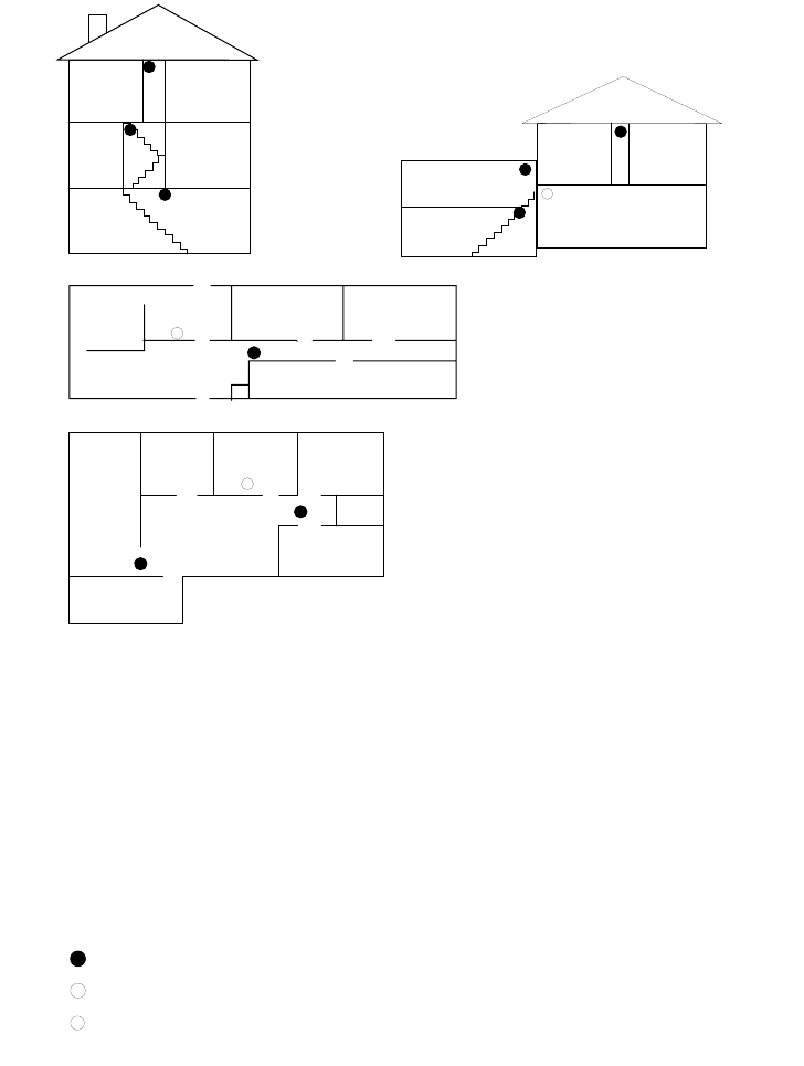
Appendix F: UL Requirements
54
The smoke detector installation shall adhere to the following:
Household Burglar Alarm System (UL 1023)
Basic system as described above plus:
• Learn Mode Door/Window Sensors (60-362)
Living
Room
Dining
Room
Basement
x
H
Hall
Bedroom Bedroom
Living
Room Recreation
Room
Basement
Hall
Bedroom Bedroom
Living
Room
Dining
Room
Hall
Bedroom Bedroom
Bedroom
Kitchen
A smoke detector should
be located on each level.
Smoke detectors should
be located between the
sleeping area and the rest
of the family living unit.
NOTE: Do not install smoke detectors where normal ambient temperatures are above
100°F or below 40°F. Also, do not locate detectors in front of AC/ Heat
registers or other locations where normal air circulation will keep smoke
from entering the detector.
NOTE: Additional information on household fire warning is available at nominal
cost from: The National Fire Protection Association, Batterymarch Park,
Quincy, MA 02269. Request Standard No. NFPA74.
H
x
Living
Room
Bedroom
Bedroom
Bedroom
Dining
Room Kitchen
TV
Room
In family living units with more
than one sleeping area, locate a
smoke detector at each area.
H
NOTE: Ceiling-mounted smoke detectors should be located in the center of the room
or hall, or not less than 4 inches from the wall. When the detector is mounted
on the wall, the top of the detector should be 4 to 12 inches from the ceiling.
Required smoke detector
Heat detector
Indicates smoke detector is optional if door is not provided between
basement and recreation rooms.
8557144a

Appendix F: UL Requirements
55
Home Health Care Signaling Equipment
(UL 1637)
Basic system as described above plus:
• Water-Resistant Panic Sensor (60-578-10-95)
The following wireless sensors and hardwire devices may be used in a UL-listed system:
Part No. Description
Wireless Sensors
60-362 Learn Mode Door/Window Sensor
60-409 Learn Mode Recessed Door/Window Sensor
60-499 Learn Mode Slim Line Door/Window Sensor
60-506 Learn Mode System Smoke Sensor
60-460 Rate-of-Rise Heat Sensor
60-452 Learn Mode Pendant Panic Sensor
60-458 Single Button Panic Sensor
60-457 Dual Button Panic Sensor
60-578 Water-Resistant Panic Sensor
60-348 Handheld Wireless Touchpad
60-453 Wall-Mount Wireless Touchpad
60-511 Learn ModeDS924i PIR Motion Sensor
60-592 DS926 PIR Ceiling Mount Motion Sensor
60-582 Learn Mode Sound Sensor (IntelliSense)
60-645-95 Wireless Smoke Sensor
(System Sensor 2300RFITI)
Hardwire Sensors/Detectors
13-360 ESL 449AT Smoke/Heat Detector
13-391 Power Supervision Module
Hardwire Sirens
60-252 Hardwire Interior Speaker & Piezo
60-278 Hardwire Interior Siren & Piezo
60-483 Slim Line Hardwire Interior Siren & Piezo
13-046 Hardwire Exterior Siren
Miscellaneous Components
60-584 SuperBus Hardwire Input Module (HIM)
60-585 SuperBus Hardwire Output Module (HOM)
60-586 SuperBus Alphanumeric Touchpad
60-620 SuperBus Energy Saver Module (ESM)
60-661 SuperBus 2-Line, LCD Alphanumeric TP
60-662 SuperBus 2-Line, V/F Alphanumeric TP

Appendix F: UL Requirements
56
The following Sensor Groups are not to be used as a primary protection circuit for UL-listed systems and are
for supplementary use only:
The following Sensor Groups shall not be used in UL-listed systems:
The following panel configuration settings shall be followed:
Note:
Common user access codes such as 1111 or 1234 should not be programmed.
The Upper Sensor Numbers shall be set as follows:
* If wall-mount touchpads are used.
No. Name
11 Extended Enty/Exit Delay
12 Twice Extended Delay
15 Instant Interior
17 Instant Interior
18 Instant Interior
19 Delayed Interior
20 Delayed Interior
24 Local Instant Auxiliary
25 Local Special Chime
No. Name
27 Output Module
28 Output Module
32 Output Module
Feature Required Setting
Phone Format ITI
Siren Time-Out 4 min., minimum
Entry Delay 40 sec., maximum
Exit Delay 56 sec., maximum
No. Sensor Name Required Setting
89 Wireless Touchpad
Supervisory or Low
Battery
ON*
90 AC Power Failure ON
91 Low Panel Battery ON
93 Automatic Phone Test ON
96 Phone Failure ON

Appendix F: UL Requirements
57
The Feature Numbers shall be programmed as follows:
The following Central Station programming shall be made:
PTFREQ: 1,1 (Automatic Phone Test Frequency = 1 day in cycle, 1 day remaining.)
No. Sensor Name Required Setting
F04 Low Battery Reports ON
F12 Alarm Restoral Reports ON
F13 Low Battery Restoral Reports ON
F15 Alarm Verification OFF
F16 Trouble Beeps Disable OFF
F20 Audio Verification Module
(AVM) Enable OFF
F21 Immediate Trouble Beeps ON
F40 Smoke Verification OFF
F41 Interior Siren Verification ON
F43 Demo Kit Mode OFF
F47 4-Hour Trouble Timer ON
Appendix F: UL Requirements
58
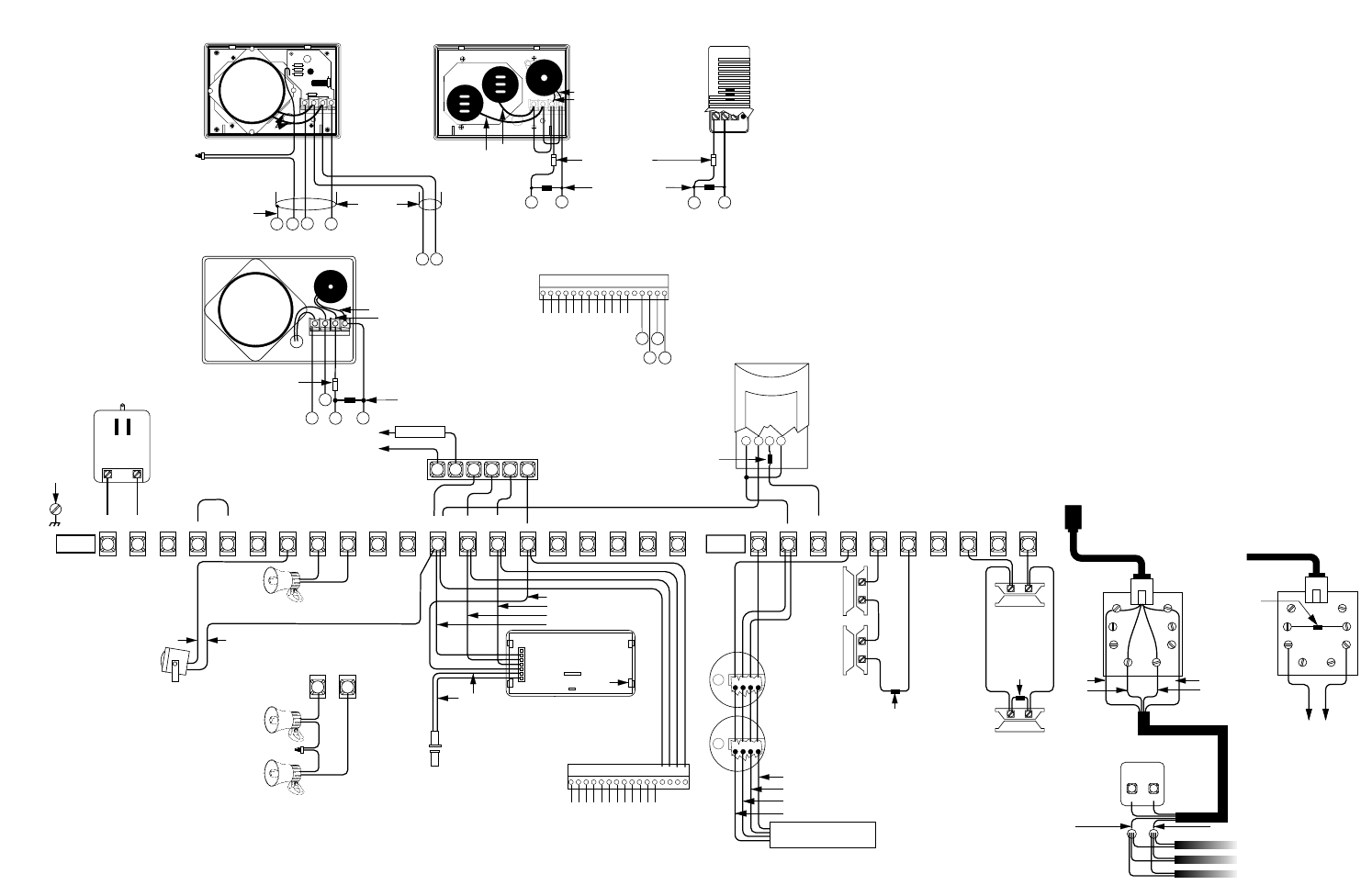
Figure E.1 Typical System Wiring
NOTE 6
LOWER
RIGHT
CHASSIS
SCREW
EARTH
GROUND
8 9
NOTE 3: 13-060 (15 WATT)
OR
NOTE 3: 13-061 (30 WATT)
8 - OHM SPEAKER
NOTE 3: 2 8-OHM SPEAKERS
IN SERIES (16 OHMS)
SPLICE
YELLOW
NOT USED
WIRING
HARNESS
49-283 TAB SLOT (4)
NOTE: 11
HARDWIRE
LOOP INPUT
BLACK
WHITE
GREEN
RED
NOTE 4: HARDWIRE
EXTERIOR SIREN
13-046
LINE
CLASS 2
16.5 VAC 50 VA
LOAD
NOTE 5: LINE CARRIER
TRANSFORMER
60-678
6
12 3 4 5
NOTE 8 & 9: SUPERBUS
ENERGY SAVER MODULE
60-620
TO FURNACE
THERMOSTAT
RED
BLACK
NOTES 2 & 3: SPEAKER/PIEZO
60-252
1 2 3 4 5 6 7 8 9 10 11 12 13 14 15 16 17 18 19 20
16.5
VAC 16.5
VAC +DC
(SIREN) GND SIREN
COM SIREN
N/O
SIREN
N/C VOICE
SIREN VOICE
SIREN TP
VOICE TP
VOICE +12V
DC OUT GND
BUS
ABUS
B FTC GND
+INT
SIREN -INT
SIREN AVM
MIC
TERMINAL
STRIP 1
NOTES 8 & 10: SUPERBUS
ALPHANUMERIC TOUCHPAD
60-586
4.7k Ohm
EOL RESISTOR 49-365
(LOCATE AT PIEZO)
BLACK
RED
VOICE
SIREN VOICE
SIREN
OR
NOTE 5: STANDARD
TRANSFORMER
60-679
IN 4001 DIODE 07-001
(LOCATE AT PIEZO)
1
23
4
21 22 23 24 25 26 27 28 29 30
+12V
DC SW GND ZONE
1
TERMINAL
STRIP 2
ZONE
2GND ZONE
3ZONE
4GND ZONE
5ZONE
6
BRN GRY
GRN RED
RED
GREEN
WHITE OR YELLOW
BLACK
TELCO
PROTECTOR
BLOCK
GRN RED
(A) (B)
SPLICE
WIRE
GREEN(C) RED(D)
BLACK WHITE OR YELLOW
TO
PREMISES
PHONES
NOTE 16: RJ-31X
(CA-38A)
PHONE JACK
NOTE 13:
NORMALLY
OPEN
(N/O)
CONTACTS
IN PARALLEL
4.7k Ohm
EOL RESISTOR
49-365
4.7k Ohm
EOL RESISTOR
49-365
NOTE 13:
NORMALLY
CLOSED
(N/C)
CONTACTS
IN SERIES
LP
NOTE 13: PIR MOTION SENSOR
13-082
-
+LN
4.7k Ohm
EOL RESISTOR
49-365
(LOCATE AT
SENSOR)
PHONE
CONNECTIONS
DUAL DB-8
PHONE CORD
49-426
NOTES 13,14 & 15:
LISTED HARWIRE
SMOKE/HEAT
DETECTOR SUCH
AS ESL 449AT
1
23
4
NOTES 14 & 15:
POWER SUPERVISON MODULE
60-391
RED
BLACK
GREEN
WHITE
NOTE 17: TAMPERING THE
RJ-31X (CA-38A)
PHONE JACK (OPTIONAL)
4.7k Ohm
EOL RESISTOR
49-365
DUAL DB-8
PHONE CORD 49-425
TO PANEL
6, BLU
7, YEL
3, ORG
2, BLK
TO PANEL HARDWIRE
ZONE TERMINALS.
NOTE 2: HARDWIRE INTERIOR SIREN, 60-278
IN 4001 DIODE 07-001
(LOCATE AT SIREN)
4.7k Ohm
EOL RESISTOR 49-365
(LOCATE AT SIREN)
NOTES 2 & 7: SLIM LINE HARDWIRE
INTERIOR SIREN AND PIEZO, 60-483-01
BLACK
SPLICE YELLOW
CABLE
SHIELD
WIRE
WIRE IN
SEPARATE
CABLES
NOTE1: AUDIO VERIFICATION MODULE, 60-677
BLACKRED
BLACK
RED
12345678910 11 12 13 14 15 16
LOOP 1
COMMON
LOOP 2
LOOP 3
LOOP 4
COMMON
LOOP 5
LOOP 6
LOOP 7
LOOP 8
COMMON
COMMON
NOTES 8,12,13 & 14: SUPERBUS
HARDWIRE INPUT MODULE
(HIM) 60-584
8557139C.DS4
NOTE 4
NOTE 18
18
17
18
17
9
8
420 19 12
18
17
8
9
(INSTALL AT LAST DEVICE)
USE IN AND OUT
(DAISY-CHAIN)
WIRING METHODS ONLY
13
1 COM
1 N/C
1 N/O
2 COM
2 N/C
2 N/O
3 COM
3 N/C
3 N/O
4 COM
4 N/C
4 N/O
12345678910 11 12 14 15 16 17
13
NOTE 8
SUPERBUS HARDWIRE OUTPUT
MODULE (HOM) 60-585
12 14
15
Table E.4 System Wiring Notes
1. A maximum of two Audio Verification Modules are allowed. Wire multiple speakers in series and the remaining
(power and microphone) wires in parallel. Use shielded cables to prevent cross talk between the speaker and
microphone.
2. Wire multiple piezo locations in parallel (daisy chain). Mount the required diode at each piezo location as
shown with the cathode (band marking) towards the piezo device terminal. Mount a single EOL resistor at the
last piezo in the chain.
3. A maximum of two speakers are allowed. Wire multiple speakers in series only. Wiring more than two speak-
ers or multiple speakers in parallel can result in permanent damage to the panel.
4. Jumper terminals 4 to 5 to supply GND to exterior SIREN COM terminal. To avoid bothering neighbors unnec-
essarily during initial system testing, leave exterior siren(s) disconnected at the panel until you are ready to
test them.
5. Both line carrier (60-678) and nonline carrier (60-679) AC power transformer types are wired the same. Do not
plug transformer into any AC receptacle controlled by a switch. AC power must not be interrupted. Do not
short the transformer outputs together. The transformer contains an internal fuse that will permanently disable
the output if shorted.
6. Connect the right-bottom panel board mounting screw to electrical ground (if the installation site has a true
electrical ground). Cold water pipe grounding can be used if it is an uninterrupted metal pipe.
7. Only high-volume Slim-Line siren sounds are used. Internal jumpers and switches have no effect.
8. All SuperBus devices such as Energy Saver, Hardwire Input and Output Modules, and Alphanumeric Touch-
pads must have unique unit number (address) settings. Devices with the same (conflicting) address will not
function properly. Default settings are ok for one module and one touchpad. Refer to instructions text for set-
ting unit numbers (addresses).
9. Refer to the Installation Instructions shipped with the Energy Saver Module for thermostat wiring details.
10. If more than one alphanumeric touchpad is required, wire all touchpad harnesses in parallel, but only connect
one touchpad until programming is complete and tested. Additional touchpads require their touchpad unit
numbers to be changed from the factory default. Refer to touchpad installation instructions text.
11. The touchpad hardwire loop is supplementary and is not intended for use as a primary initiating circuit
because the loop is not end-of-line supervised.
12. Wire Hardwire Input Module hardwire zones as shown for the panel. Mount a single EOL resistor as shown at
the last device in the chain.
13. Zone (loop) terminal shown is an example. Any zone (loop) terminal may be used. Install EOL resistors across
all unused zone (loop) inputs and GND (common on Hardwire Input Module).
14. Power Supervision Module is required for supervised (UL-investigated) applications. Wire multiple or super-
vised hardwire smoke/heat detectors only as shown.
15. For nonsupervised applications, replace the power supervision module with single EOL resistor across termi-
nals 3 and 4 of the last detector in the chain.
16. Some telephones are polarity-sensitive. Green and red wires may need to be reversed.
17. Phone jack tampering is optional. If used, assignment to sensor group 8 (special intrusion) is recommended.
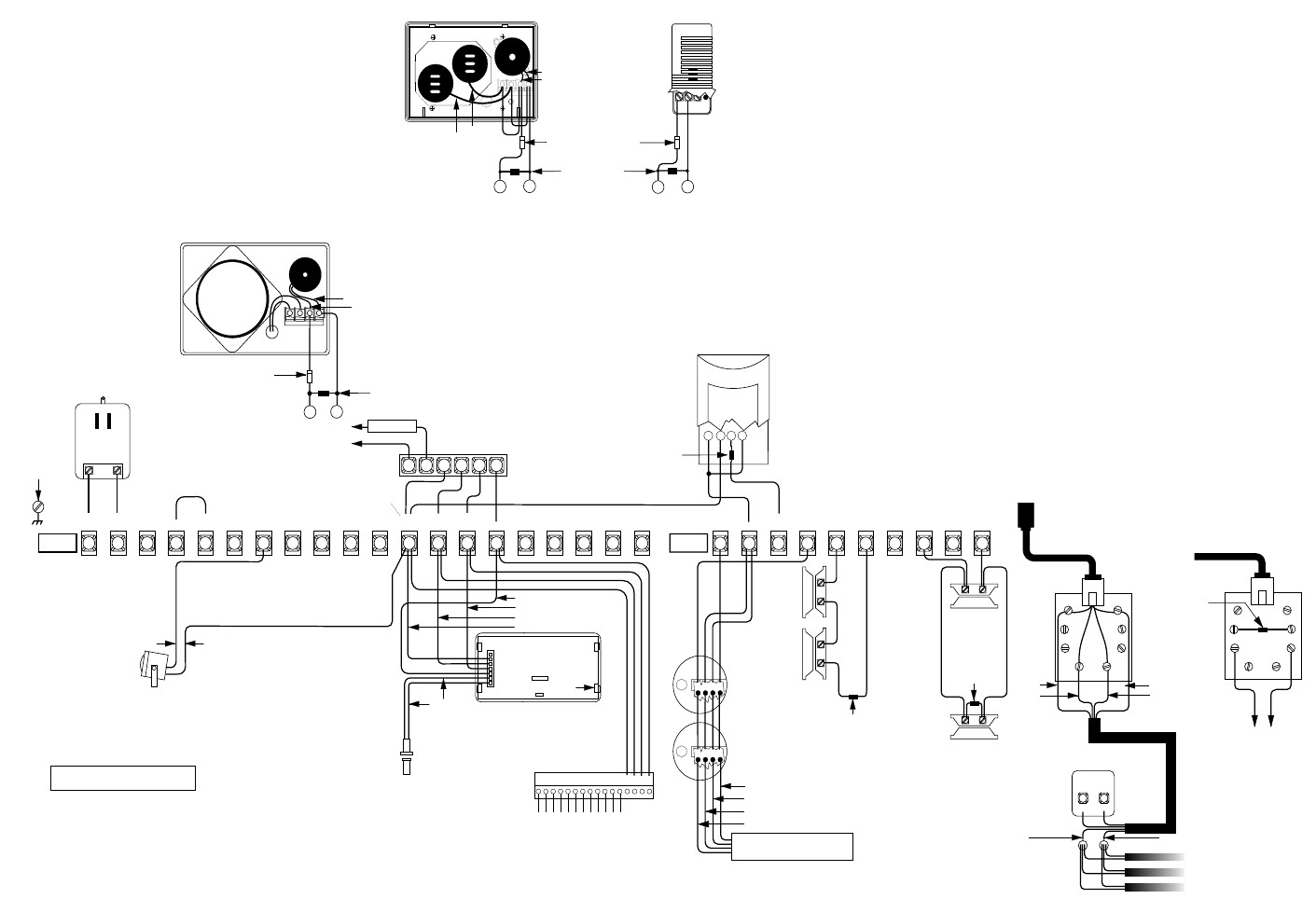
NOTE 5:
LOWER
RIGHT
CHASSIS
SCREW
EARTH
GROUND
YELLOW
NOT USED
WIRING
HARNESS
49-283 TAB SLOT (4)
NOTE 10:
HARDWIRE
LOOP INPUT
BLACK
WHITE
GREEN
RED
NOTE 3: HARDWIRE
EXTERIOR SIREN
13-046
LINE
CLASS 2
16.5 VAC 50 VA
LOAD
NOTE 4: LINE CARRIER
TRANSFORMER
60-678
6
12 3 4 5
NOTE 7 & 8: SUPERBUS
ENERGY SAVER MODULE
60-620
TO FURNACE
THERMOSTAT
RED
BLACK
NOTES 1 & 2: SPEAKER/PIEZO
60-252
1 2 3 4 5 6 7 8 9 10 11 12 13 14 15 16 17 18 19 20
16.5
VAC 16.5
VAC +DC
(SIREN) GND SIREN
COM SIREN
N/O
SIREN
N/C VOICE
SIREN VOICE
SIREN TP
VOICE TP
VOICE +12V
DC OUT GND
BUS
ABUS
BFTC GND
+INT
SIREN -INT
SIREN AVM
MIC
TERMINAL
STRIP 1
NOTES 7 & 9: SUPERBUS
ALPHANUMERIC TOUCHPAD
60-586
4.7k Ohm
EOL RESISTOR
ITI PART NO. 49-365
(LOCATE AT PIEZO)
BLACK
RED
OR
NOTE 4: STANDARD
TRANSFORMER
60-679
ITI PART NO. 07-001 DIODE
(LOCATE AT PIEZO)
1
23
4
21 22 23 24 25 26 27 28 29 30
NOTE 17
+12V
DC SW GND ZONE
1
TERMINAL
STRIP 2
ZONE
2GND ZONE
3ZONE
4GND ZONE
5ZONE
6
BRN GRY
GRN RED
RED
GREEN
WHITE OR YELLOW
BLACK
TELCO
PROTECTOR
BLOCK
GRN RED
(A) (B)
SPLICE
WIRE
GREEN(C) RED(D)
BLACK WHITE OR YELLOW
TO
PREMISES
PHONES
NOTE 16: RJ-31X
(CA-38A)
PHONE JACK
NOTE 12:
NORMALLY OPEN
(N/O) CONTACTS
IN PARALLEL
4.7k Ohm
EOL RESISTOR
ITI PART
NO. 49-365
4.7k Ohm
EOL RESISTOR
ITI PART NO. 49-365
NOTE 12:
NORMALLY
CLOSED
(N/C)
CONTACTS
IN SERIES
LP
NOTE 12: LISTED PIR MOTION SENSOR
-
+
LN
4.7k Ohm
EOL RESISTOR
ITI PART NO. 49-365
(LOCATE AT SENSOR)
PHONE
CONNECTIONS
DUAL DB-8
PHONE CORD
49-426
NOTES 12 & 13:
LISTED HARDWIRE
SMOKE/HEAT
DETECTOR SUCH
AS ESL 449AT
1
23
4
NOTES 13: POWER SUPERVISON
MODULE
ITI PART NO. 60-391
RED
BLACK
GREEN
WHITE
NOTE 15: TAMPERING THE
RJ-31X (CA-38A)
PHONE JACK (OPTIONAL)
4.7k Ohm
EOL RESISTOR
49-365
DUAL DB-8
PHONE CORD 49-425
TO PANEL
6, BLU
7, YEL
3, ORG
2, BLK
TO PANEL HARDWIRE
ZONE TERMINALS.
NOTE 1: HARDWIRE INTERIOR SIREN, 60-278
ITI PART NO. 07-001 DIODE
(LOCATE AT SIREN)
4.7k Ohm
EOL RESISTOR
ITI PART NO. 49-365
(LOCATE AT SIREN)
NOTES 1 & 6: SLIM LINE HARDWIRE
INTERIOR SIREN AND PIEZO, 60-483-01
BLACKRED
BLACK
RED
12345678910 11 12 13 14 15 16
LOOP 1
COMMON
LOOP 2
LOOP 3
LOOP 4
COMMON
LOOP 5
LOOP 6
LOOP 7
LOOP 8
COMMON
COMMON
NOTES 7,11,12 & 13: SUPERBUS
HARDWIRE INPUT MODULE
(HIM) 60-584
8557150B.DS4
NOTE 3
18
17
18
17
18
17
N/C – INDICATES NO CONNECTION
SHALL BE MADE.
N/C N/C N/C N/C N/C N/C
(INSTALL AT LAST DEVICE)
USE IN AND OUT
(DAISY-CHAIN)
WIRING METHODS ONLY
NOTE 16
Figure F.1 UL-Listed System Wiring
Table F.1 UL-Listed System Wiring Notes
1. Wire multiple piezo locations in parallel (daisy chain). Mount the required diode at each piezo location as
shown with the cathode (band marking) towards the piezo device terminal. Mount a single EOL resistor at the
last piezo in the chain.
2. A maximum of two speakers are allowed. Wire multiple speakers in series only. Wiring more than two speakers
or multiple speakers in parallel can result in permanent damage to the panel.
3. Jumper terminals 4 to 5 to supply GND to exterior SIREN COM terminal. To avoid bothering neighbors unnec-
essarily during initial system testing, leave exterior siren(s) disconnected at the panel until you are ready to test
them.
4. Both line carrier (60-678) and nonline carrier (60-679) AC power transformer types are wired the same. Do not
plug transformer into any AC receptacle controlled by a switch. AC power must not be interrupted. Do not short
the transformer outputs together. The transformer contains an internal fuse that will permanently disable the
output if shorted.
5. Connect the right-bottom panel board mounting screw to electrical ground (if the installation site has a true
electrical ground). Cold water pipe grounding can be used if it is an uninterrupted metal pipe.
6. Only high-volume Slim-Line siren sounds are used. Internal jumpers and switches have no effect.
7. All superbus devices such as Energy Saver and Hardwire Input Modules and Alphanumeric Touchpads must
have unique unit number (address) settings. Devices with the same (conflicting) address will not function prop-
erly. Default settings are ok for one module and one touchpad. Refer to instructions text for setting unit numbers
(addresses).
8. Refer to Installation Instructions shipped with the Energy Saver Module for thermostat wiring details.
9. If more than one alphanumeric touchpad is required, wire all touchpad harnesses in parallel, but only connect
one touchpad until programming is complete and tested. Additional touchpads require their touchpad unit num-
bers to be changed from the factory default. Refer to touchpad installation instructions text.
10. The touchpad hardwire loop is supplementary and is not intended for use as a primary initiating circuit because
the loop is not end-of-line supervised. Refer to touchpad installation instructions text for further restrictions.
11. Wire Hardwire Input Module hardwire zones as shown for the panel. Mount a single EOL resistor as shown at
the last device in the chain.
12. Zone (loop) terminal shown is an example. Any zone (loop) terminal may be used. Install EOL resistors across
all unused zone (loop) inputs and GND (common on Hardwire Input Module).
13. Power Supervision Module is required. Wire multiple or supervised hardwire smoke/heat detectors only as
shown.
14. Some telephones are polarity-sensitive. Green and red wires may need to be reversed.
15. Phone jack tampering is optional. If used, assignment to sensor group 8 (special intrusion) is recommended.
16. Terminal 12 (+12VDC OUT) is rated 10.4 to 12VDC; refer to installation instructions for maximum current rat-
ings.
17. Terminal 17 (+12VDC SW) is rated 9.9 to 12VDC: refer to installation instructions for maximum current ratings.
