9 XXX Name Installation Sheet 466 5444 A Interlogix Rcr Rex Install Guide
2018-11-08
: Interlogix 466-5444-A-Interlogix Rcr Rex Install-Guide 466-5444-a-interlogix_rcr_rex_install-guide library
Open the PDF directly: View PDF ![]() .
.
Page Count: 7
- RCR-REX Request-to-Exit Dual Technology Motion Sensor Installation Guide
- Introduction
- Installation
- Figure 1: Open the cover
- Figure 2: Remove the circuit board and cradle
- Figure 3: Mounting and wiring access
- Figure 4: Basic hook-up
- Figure 5: Spike Protection
- Figure 6: RCR-REX and a keycard reader
- Figure 7: Monitor door contacts (first option)
- Figure 8: Monitor door contacts (second option)
- Figure 9: Panic Button
- Initial Power Up
- Figure 10: PIR Detection Pattern
- Figure 11: PIR Pattern Adjustment
- Figure 12: Radar Detection Pattern
- Figure 13: Range Adjustment Control
- Operation
- Figure 14: Fail Safe/Fail Secure Modes Relay Contacts
- Figure 15: Mask installation
- Specification
- Product Ordering
- FCC Compliance
- Disclaimer
© 2018 UTC Fire & Security. All rights reserved. 1 / 7 P/N 466-5444 • REV A • 8NOV18
RCR-REX Request-to-Exit
Dual Technology Motion Sensor
Installation Guide
Introduction
This is the Interlogix RCR-REX Request-to-Exit Dual
Technology Motion Sensor Installation Instructions for
models RCR-REX-W, RCR-REX-B, and RCR-REX-G.
Installation
Determine if the sensor will be ceiling or wall mounted. Avoid
locating the sensor between double doorways where objects
can be inserted through a crack to gain unauthorized entry.
CAUTION: When handling the sensor, do not touch the lens
window.
To install the sensor, do the following:
1. To open the front cover, insert a small screwdriver into
the bottom of the locking tab and pull upward (Figure 1).
Figure 1: Open the cover
CAUTION: You must be free of static electricity before handling
sensor circuit boards. Touch a grounded, bare metal
surface before touching circuit boards or wear a
grounding strap.
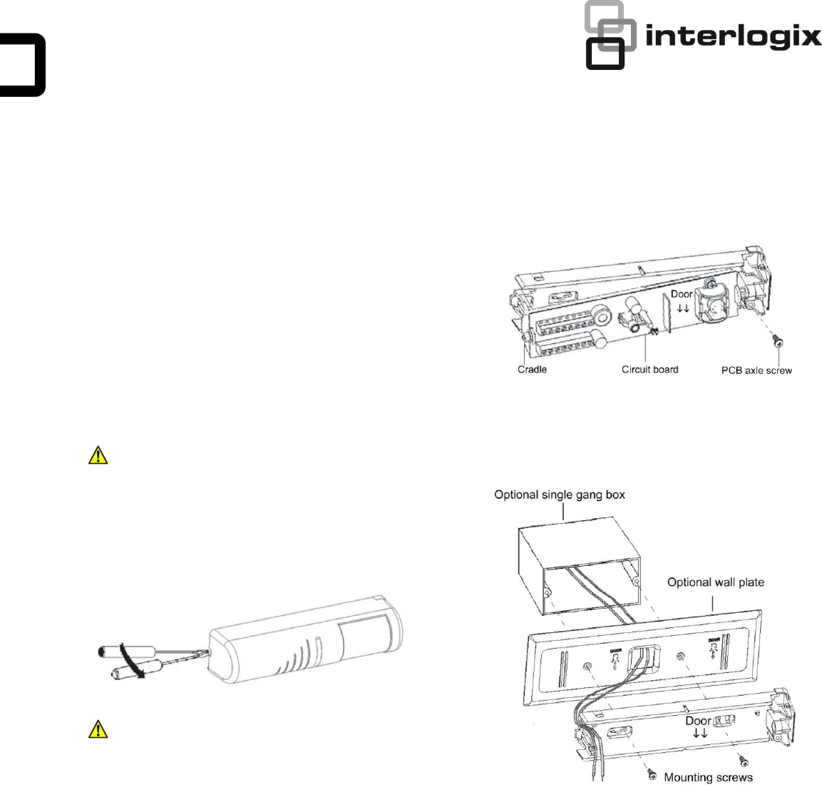
2. Remove the screw holding the circuit board (PCB)
cradle axle to the back housing and carefully remove
the circuit board with cradle from the housing (Figure 2).
Figure 2: Remove the circuit board and cradle
3. Route wiring to the sensor mounting location. If you are
using the wall plate, pull the wires through the cable
entry hole (Figure 3).
Figure 3: Mounting and wiring access
4. Insert the mounting screws into the back (wall mount) or
top (ceiling mount) mounting screw holes to fasten the
back housing and wall plate, if used, to the wall or
ceiling (Figure 3).
5. Reinstall the PCB/cradle and secure in place with the
PCB axle screw (Figure 2).
6. Complete wiring connection (See Wiring on page 2).
7. Swing the front cover in place and walk test the sensor
for appropriate coverage and function (see Initial power
up on page 4.
2 / 7 P/N 466-5444 • REV A • 8NOV18
Wiring
This section provides examples of different wiring options.
The options are all shown in the failsafe mode.
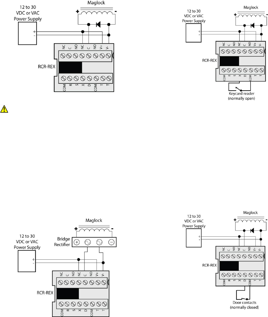
Basic Hook-up
Figure 4 shows the basic hook-up for the RCR-REX, a
power supply and a magnetic lock. When the sensor sees
motion, power is removed from the magnetic lock.
Figure 4: Basic hook-up
CAUTION: For DC powered systems, if the door lock does not
contain a diode across the coil winding, install a diode
across the door lock to prevent degradation of the lock
relay contacts. The diode should have a current rating
greater than the maximum lock current. Install the
diode so that the cathode end with the bar is
connected to the positive side of the coil.
Spike Protection
Many magnetic locks and electric door strikes have built in
spike (diode) protection. If the lock is not spike protected,
install a bridge rectifier, such as a KBL005, between the
relay contacts and the magnetic lock/door strike as shown in
Figure 5.
Figure 5: Spike Protection
Note: Failure to spike protect the sensor may result in shortening
the life of the relay contacts.
RCR-REX and a Keycard Reader
Figure 6 shows the wiring normally used when a keycard
reader is on one side of the door and the RCR-REX is on the
other side of the door. Both swiping a keycard or the
detection of motion by the RCR-REX will remove power from
the magnetic lock.
Figure 6: RCR-REX and a keycard reader
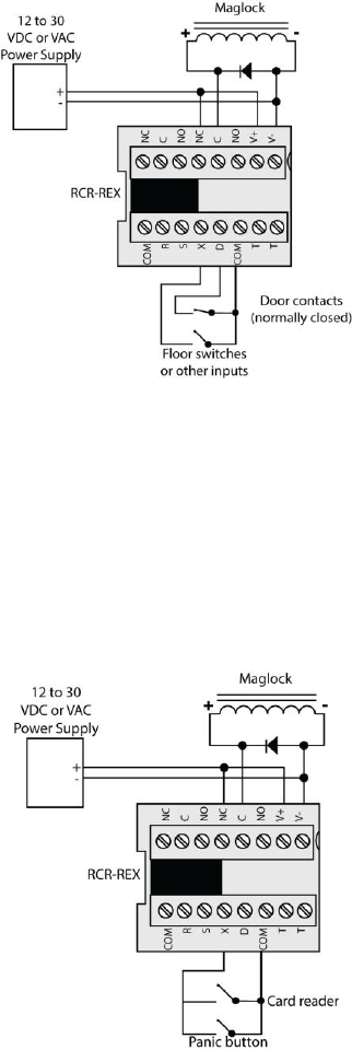
Monitor Door Contacts (first option)
In the monitor door contacts mode, a person entering the
sensor’s field of view will activate the relay and timer. Door
contacts connected to terminal D will monitor if the door is
open or closed. If the relay timer gets to ten seconds or less
(if set for 16 seconds or greater) and the door is still open,
the RCR-REX internal sounder will activate. The sounder will
also active if the door is opened without first activating the
sensor or keycard input. The sounder will remain on until the
door is closed or by someone moving in the field of view
(Figure 7).
Figure 7: Monitor door contacts (first option)
P/N 466-5444 • REV A • 8NOV18 3 / 7
Monitor Door Contacts (second option)
If the sensor is activated but the door is not opened, the
relay will drop out after ten seconds. If the sensor is
activated and the door is opened, and then closed, the relay
will drop out after two seconds. This prevents unauthorized
people from entering (Figure 8).
Figure 8: Monitor door contacts (second option)
Panic Button
Many fire codes require a panic button to be part of the
installation. The RCR-REX has an X (external) input (see X
(input) external) for a normally open panic button or an
internal timer panic button. When X input is grounded, the
door will open. Two normally open devices may be
connected to the X input (Figure 9).
Figure 9: Panic Button
NC, C, NO (I/O) Monitor Relay Section
Connect the monitor relay terminals across the normally
closed contacts (NC) of the door switch and across the
access control system. If there is no access control system,
connect the normally closed contacts of the door switch
across the monitor relay terminals.
R (input) Arm
This pin is used to enable and disable the unit with an
external signal. The unit will be disabled when R is grounded
for more than 10 seconds. Thereafter, when R is
ungrounded, the unit will be enabled. Motion detected by the
unit up to 10 seconds after R is grounded and at least 100
milliseconds after R is ungrounded will start the relay timer.
This pin must be switched with a dry contact or an open
collector transistor referenced to COM (ground).
S (input) Sounder
This pin allows external control of the sounder that takes
precedence over all other sounder modes. If the unit is
powered up with S ungrounded, then the unit assumes that
S is unused.
Whenever S is grounded after power up, the unit assumes
that S is being used to externally activate the sounder.
Thereafter, when S is ungrounded for at least 100
milliseconds, the sounder will unconditionally turn on and
stay on until S is grounded.
This pin must be switched with a dry contact or an open
collector transistor referenced to COM (ground).
X (input) External
This pin can be used by card readers, keypads, remote push
buttons, and key locks to cause the sensor to start a timing
cycle.
If X is pulled to ground for at least 500 milliseconds and less
than 3 seconds, the lock/monitor relay will unlock the door
and the lock timer will start as if a person walked into the
detection area. If X is grounded for more than 3 seconds,
then the relay will stay in the unlocked state until X is
allowed to go high. When X goes high and if the door is still
open, the sounder will produce a beeping tone and the relay
will remain in the unlocked state until the door closes. When
the door closes, the relay will lock the door and shunt the
door switch.
This pin must be switched with a dry contact or an open
collector transistor referenced to COM (ground).
D (input) Door
This pin is used to detect the state of the door switch. The
door switch must be connected between pins D and COM
(ground). If the unit is powered up with D ungrounded, the
unit assumes that D is unused. If D is ever grounded after
the unit is powered up, the unit assumes that D is being
used to sense door position and the sounder will beep (if
enabled) when the door is left open.
If used, this pin must be switched with a dry contact or an
open collector transistor referenced to COM (ground). See
S2-7 (door monitor mode) on page 4.
4 / 7 P/N 466-5444 • REV A • 8NOV18
T and T Tamper Switch
These two pins connect to the tamper switch, which opens
when the housing cover is opened.
COM (I/O) Common or Ground
These two pins are connected to ground and serve as the
ground reference when using pins R, S, X, and D.
DIP Switch Options
The factory default (D) setting is on for all switches.
S2-1 (sounder enable)
On. Sounder is enabled for all modes (D).
Off. Sounder is completely disabled.
S2-2 (LED control)
On. LED is enabled (D).
Off. LED is disabled except during warm-up.
S2-3 (timer reset mode)
On. Relay timer does not reset with motion (D).
Off. Relay timer resets with motion.
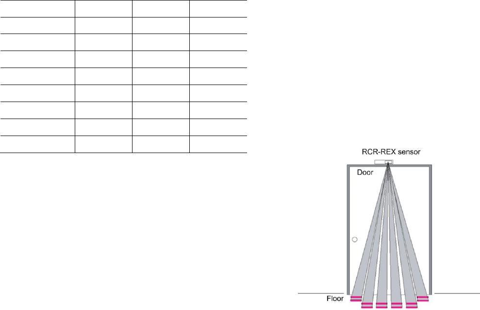
S2-4, S2-5, S2-6 (relay time)
These switches determine how long the lock relay stays
energized when motion is detected (Table 1).
Table 1: Relay Time Settings
Relay time
S2-4
S2-5
S2-6
1/2 seconds (D)
On
On
On
1 second
On
On
Off
2 seconds
On
Off
On
4 seconds
On
Off
Off
8 seconds
Off
On
On
16 seconds
Off
On
Off
32 seconds
Off
Off
On
64 seconds
Off
Off
Off
S2-7 (door monitor mode)
On. Monitor the door switch (D).
Off. Do not monitor the door switch.
S2-8 (relay mode)
On. Fail safe mode (D) is enabled.
Off. Fail secure mode is enabled.
Initial Power Up
After mounting and wiring the sensor, apply AC or DC power
to the input power terminals (V+ and V-). Allow at least 2
minutes following power up for the sensor to stabilize before
conducting any tests.
To walk test the detection pattern, approach the door from all
directions and watch the walk test LED for detection. See
Pattern Adjustment if changes are required in the detection
area.
Reassemble the sensor and completely walk test again
following any lens adjustment.
To select the appropriate relay time, set the DIP switches as
shown in DIP Switch Options on page 4.
LED Indicator
The LED turns red for the duration of the lock relay time
when motion is detected and flashes twice per second
during the 20-second warm-up period. The LED turns yellow
when the radar detects motion. The LED turns green when
the passive infrared (PIR) detects motion.
Internal Sounder
A continuous tone will sound 15 seconds prior to the end of
the relay timer period. A beeping tone will sound at the end
of the external input (X) signal if the door is open.
Pattern Adjustment
The RCR-REX has both PIR and radar detection patterns
that may be adjusted independently.
PIR Detection Pattern
Figure 10 shows the passive infrared (PIR) detection pattern.
Figure 10: PIR Detection Pattern
P/N 466-5444 • REV A • 8NOV18 5 / 7
To adjust the PIR detection pattern toward or away from the
door opening, do the following:
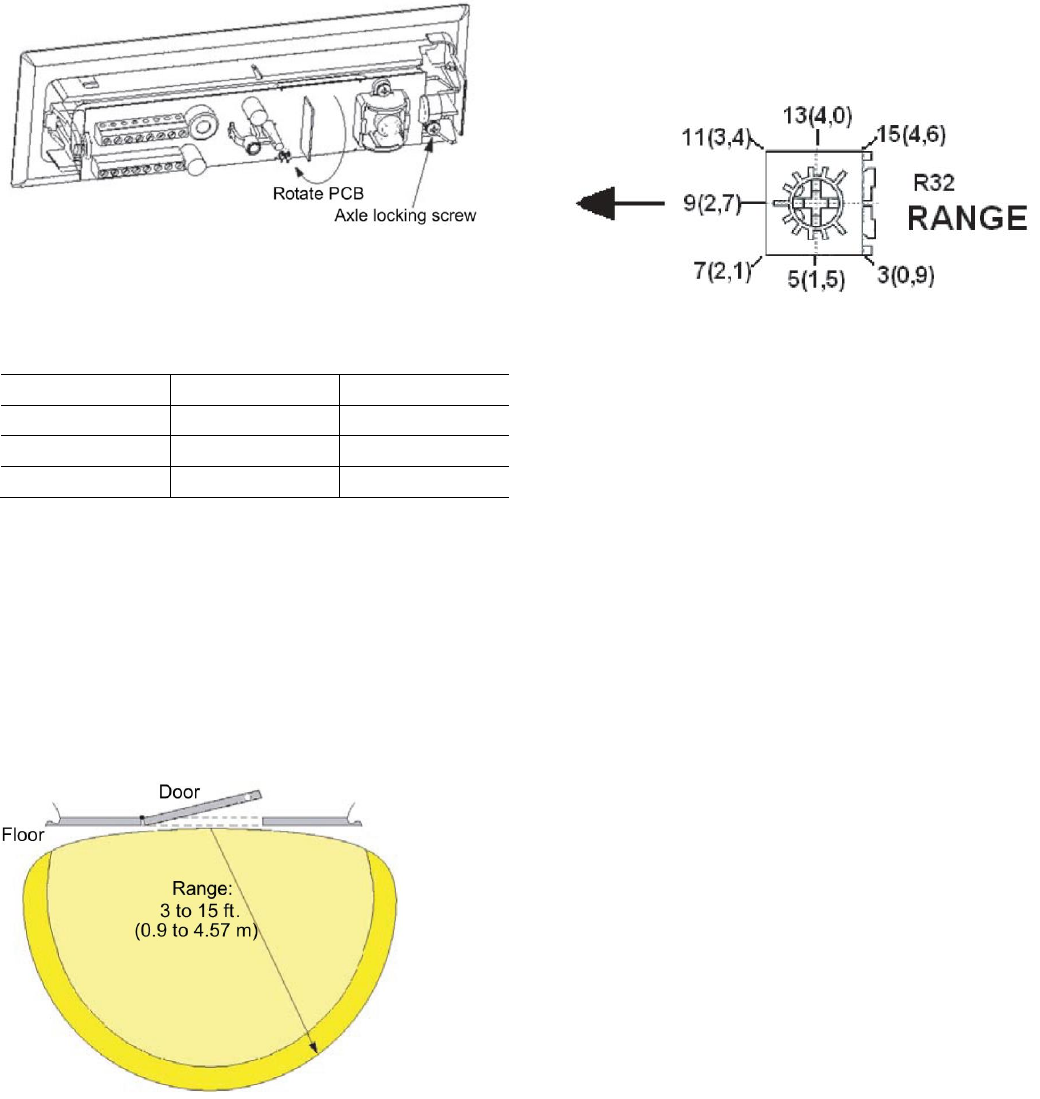
1. Open the sensor cover; see “Figure 1: Open the cover”
on page 1 and loosen the PCB axle screw (Figure 11).
Figure 11: PIR Pattern Adjustment
2. Rotate the PCB to the desired position and tighten the
PCB axle screw. Table 2 gives the suggested angle for
a given mounting height.
Table 2: Suggested Angles
Mounting height
Wall angle
Ceiling angle
7 ft. (2.1 m)
-10°
+10°
10 ft. (3.0 m)
-20°
+20°
15 ft. (4.6 m)
-30°
+30°
3. Close the cover.
4. Test to be sure undesired sources of motion will not be
detected.
Radar Detection Pattern
Figure 12 shows the radar detection pattern.
Figure 12: Radar Detection Pattern
You can adjust the radar range from 3 to 15 ft. (0.9 to 4.57
m). To adjust the range, rotate the range adjustment control
(Figure 13) to the desired position. The radar range is not
affected by the PCB rotation during PIR range adjustment.
The radar range can be set to just above the floor, to prevent
door activation from objects that have been slipped under
the door. After adjusting the radar range, carefully test to be
sure undesired sources of motion will not be detected.
Figure 13: Range Adjustment Control
Operation
By connecting the lock relay in series with the door lock and
the monitor relay in parallel to the door switch and alarm
circuit, the sensor will allow normal egress and will monitor
alarms from the door being held or forced open. The sensor
will monitor the operation of the door switch without affecting
the access control system.
When the sensor detects motion, the lock relay contacts
open, unlocking the door, and the monitor relay contacts
close, preventing an alarm from being sent to the access
control system for a fixed time. The time is selected with the
DIP switch from 1/2 to 64 seconds or until reset by the
sensor. See DIP switch options on page 4.
If the sensor does not detect the opening of the door switch
within 10 seconds of sensor activation; the lock and monitor
relays will return to their normal condition. If the relay timer is
set to 8 seconds or shorter, the lock relay will change back
to the normal condition when the relay timer times out. After
the door switch opens and closes, the sensor will
automatically cancel any remaining relay time if the door
switch remains closed for at least 2 seconds.
The sensor’s sounder will produce a continuous tone to warn
of an open door 15 seconds before the timer closes the lock
relay contacts and opens the monitor relay contacts. Closing
the door will silence the sounder. New movement within the
detection area will restart the timer and reset the sounder. If
the door is still open when the timer ends, the monitor relay
contacts will open, which will cause an alarm signal to be
sent to the access control system.
6 / 7 P/N 466-5444 • REV A • 8NOV18
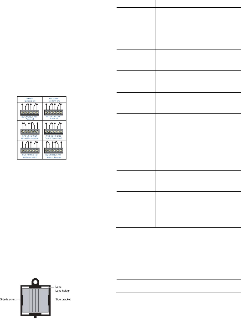
Fail Safe/F ail Secure Modes
The lock relay operates in the failsafe mode (factory default)
when the lock relay state during alarm is the same state as
when the unit is not powered. During the power up period,
the relay will be in the same state as during normal
unalarmed operation. The lock relay operates in the fail
secure mode where the lock relay state during normal
unalarmed operation is the same as when the unit is not
powered. During the power up period, the relay will be in the
same state as during the alarm period.
Note: The fail secure mode must be authorized by your local
authority. Listed panic hardware shall be used to allow
emergency exit from the protected area.
Figure 14 shows the fail safe and fail secure modes relay
contacts.
Figure 14: Fail Safe/Fail Secure Modes Relay Contacts
Mask Installation
The RCR-REX has a mask included that allows you to adjust
the PIR field of view. This may be necessary for some
installations when the unit may be tripped by non-exiting foot
traffic or other erroneous sources that are with the detection
area.
To install the mask, do the following:
1. Remove the appropriate segments of the mask to
include the desired area of detection.
2. Open the RCR-REX cover and locate the PIR lens.
3. Slip the mask into the two side brackets that hold the
PIR lens in place (Figure 15). Be careful not to dislodge
the lens.
4. Close the cover.
Figure 15: Mask installation
Specification
Voltage
12 to 30 VAC or VDC
Current
23mA typical, 27mA maximum at 12 VDC
15mA typical, 17mA maximum at 24 VDC
31mA typical, 38mA maximum at 12 VAC
26mA typical, 29mA maximum at 24 VAC
Time delay
1/2, 1, 2, 4, 8, 16, 32, 64 seconds ± 10%,
selectable
Alarm output
DPDT (2 Form C)
Maximum loop
rating
2 A at 30 V AC/DC
Loop type
Closed, open
Tamper output
50 mA at 30 VDC
Wire gauge
AWG 14 to 22 (18 to 22 recommended)
Operating
temperature
-20 to 122°F (-29 to 50°C)
Relative humidity
10 to 95% non-condensing
RFI immunity
20V/meter from 80 MHz to 1 GHz
Static immunity
8k V
Lightning
immunity
2.4kV, 1.4 Joules
Radar frequency
5.84 GHz
Range
Depth
Width
3 to 15 ft. (0.9 to 4.57 m)
7.9 ft. (2.4 m)
Mounting height
7 to 15 ft. (2.13 to 4.57 m) typical
Dimensions (W x
H x D)
7.4" x 1.76" x 1.85"
(187.8 x 44.7 x 47 mm)
Color
Off-white, black, gray
Listings
C UL-US
Industry Canada
CE (pending)
FCC
Product Ordering
Product
Description
RCR-REX-W
RCR-REX request-to-exit dual technology
motion sensor, off-white
RCR-REX-B
RCR-REX request-to-exit dual technology
motion sensor, black
RCR-REX-G
RCR-REX request-to-exit dual technology
motion sensor, gray
Note: The equipment should be installed in accordance with the
National Electrical Code, ANSI / NFPA70.

P/N 466-5444 • REV A • 8NOV18 7 / 7
FCC Compliance
This device complies with Part 15 of the FCC rules.
Operation is subject to the following three conditions:
1. This device may not cause harmful interference.
2. This device must accept any interference received,
including interference that may cause undesired
operation.
3. Changes or modifications not expressly approved by the
party responsible for compliance could void the user’s
authority to operate the equipment.
FCC ID: CGGAA2
Disclaimer
Information in this document is subject to change without
notice. No part of this document may be reproduced or
transmitted in any form or by any means, electronic or
mechanical, for any purpose, without the express written
permission of UTC Fire & Security Americas Corporation,
Inc.
Contact Information
www.utcfireandsecurity.com or www.interlogix.com
For customer support, see www.interlogix.com/customer-support
© 2018 UTC Fire & Security Americas Corporation, Inc.
Interlogix is part of UTC Climate Controls & Security, a unit
of United Technologies Corporation. All rights reserved.
November 8, 2018
