Ultrasync Modular Hub Reference Manual
2018-03-05
: Interlogix Ultrasync-Modular-Hub-Reference-Manual ultrasync-modular-hub-reference-manual library
Open the PDF directly: View PDF ![]() .
.
Page Count: 261 [warning: Documents this large are best viewed by clicking the View PDF Link!]
Modular Hub
P/N 466-5261 • REV D * ISS 17NOV17 ©2016 United Technologies Corporation
REFERENCE MANUAL
Security
&
Home Automation

2 P/N 466-5261 • REV D ISS 17NOV17 UltraSync Modular Hub Reference Manual ©2016 United Technologies Corporation
PLEASE READ THE IMPORTANT SAFETY AND LEGAL INFORMATION INCLUDING
WARNINGS, WARRANTY DISCLAIMERS, AND LIMITATIONS OF LIABILITY BEFORE
USING THIS PRODUCT.
THIS INFORMATION CAN BE FOUND IN THE PRODUCT WARNINGS AND
DISCLAIMERS SECTION BEGINNING ON PAGE 237.
About navigating this electronic document:
Throughout this document there are navigational links.
Wherever you see this symbol
...C...
you can click on it to return to the table of contents.
Wherever you see this symbol
...... I.....
you can click on it to return to the index.
Wherever you see underlined blue text you can click on it to navigate to that reference.
Whenever you navigate to a new page, you can go back using Alt + (left arrow)
3 P/N 466-5261 • REV D ISS 17NOV17 UltraSync Modular Hub Reference Manual ©2016 United Technologies Corporation
Contents
Welcome .............................................................................................................................. 7
Features & Benefits ........................................................................................................... 7
System Capacity ............................................................................................................... 7
System Components .......................................................................................................... 9
1.1 CPU ...................................................................................................................... 9
1.2 Touch Screen Keypad ........................................................................................ 11
1.3 Zone Expansion Modules ................................................................................... 12
1.4 Relay Expansion Modules .................................................................................. 14
1.5 Wireless Expansion Modules .............................................................................. 16
1.6 Cellular Module ................................................................................................... 17
1.7 Residential Plastic Enclosure .............................................................................. 18
1.8 Commercial Metal Enclosure .............................................................................. 19
1.9 Smart Power Supply ........................................................................................... 20
1.10 Batteries ............................................................................................................. 26
1.11 Transformer ........................................................................................................ 26
2 Hardware Installation ..................................................................................................... 27
Minimum System Requirements ..................................................................................... 27
Choose a Location .......................................................................................................... 27
2.1 Power Requirements .......................................................................................... 27
2.2 Grounding ........................................................................................................... 28
2.3 Shielding ............................................................................................................. 28
2.4 Termination Jumpers .......................................................................................... 28
2.5 Cable Requirements ........................................................................................... 28
2.6 Ferrite Installation ............................................................................................... 29
2.7 Wiring Diagram ................................................................................................... 30
2.8 Terminal Diagram ............................................................................................... 32
2.9 LED Diagram ...................................................................................................... 33
3 Programming Methods .................................................................................................. 34
3.1 Programming via Web Server ............................................................................. 35
3.1.1 Connect to LAN .................................................................................................. 35
3.1.2 Retrieve the CPU IP address .............................................................................. 35
3.1.3 Manually Assign an IP Address .......................................................................... 35
3.1.4 Login to the Web Server ..................................................................................... 36
3.1.5 Troubleshooting LAN Connections ..................................................................... 36
3.2 Programming via UltraSync ................................................................................ 36
3.2.1 Set Up a Web Access Passcode for UltraSync ................................................... 36
3.2.2 Connect via UltraSync Application ...................................................................... 37
3.2.3 Check LAN Connection to UltraSync Servers ..................................................... 39
3.2.4 Troubleshooting UltraSync Setup ....................................................................... 40
3.3 Programming via DLX 900 Management Software ............................................. 41
3.3.1 Enable Remote Access for DLX 900 .................................................................. 41
3.3.2 Connect using DLX 900 on LAN ......................................................................... 41
3.3.3 Remotely Connect using DLX 900 on UltraSync ................................................ 41
3.4 Programming via On-Site Keypad ...................................................................... 42
3.5 Recommended Items to Change ........................................................................ 42
4 The UltraSync App ......................................................................................................... 44
4.1 Install UltraSync App .......................................................................................... 44
4 P/N 466-5261 • REV D ISS 17NOV17 UltraSync Modular Hub Reference Manual ©2016 United Technologies Corporation
4.1 Using the App ..................................................................................................... 45
4.2 UltraSync Color Codes ....................................................................................... 48
5 System Settings ............................................................................................................. 50
5.1 Learn in Sensors ................................................................................................. 50
5.2 Learn in a Keyfob ................................................................................................ 55
5.3 Programming Areas ............................................................................................ 58
5.4 Programming the System ................................................................................... 61
5.5 Programming Reporting and Notifications .......................................................... 64
5.6 Programming the Network .................................................................................. 66
5.7 Programming Automations (Scenes) .................................................................. 69
5.8 Programming Schedules .................................................................................... 72
5.9 Programming Holidays ....................................................................................... 74
5.10 Lock PIN Share ................................................................................................... 76
5.11 Programming Cameras ....................................................................................... 77
Add a Camera Method 1 – Automatic Discovery.......................................................... 77
Viewing Cameras in UltraSync ..................................................................................... 77
5.12 Check Event History ........................................................................................... 78
5.13 Check Connection Status ................................................................................... 79
5.14 Check Details ...................................................................................................... 79
6 Advanced Programming Using Web Server ................................................................ 80
6.1 Advanced Programming, System ....................................................................... 82
6.2 Advanced Programming, Sensors ...................................................................... 93
6.3 Advanced Programming, Areas .......................................................................... 97
Notes on Force Arming, Bypass, and Auto-Bypass ................................................... 101
6.4 Advanced Programming, Reporting and Notifications ...................................... 108
Configure Email Reporting ......................................................................................... 111
6.5 Advanced Programming, Communicator .......................................................... 112
6.6 Advanced Programming, Schedules ................................................................. 121
6.7 Advanced Programming, Actions ...................................................................... 123
6.8 Advanced Programming, Auto Arm-Disarm ...................................................... 128
6.9 Advanced Programming, Devices and Enrollment ............................................ 130
6.9.1 System Devices ............................................................................................... 130
6.9.1.1 Control Devices ............................................................................................. 131
6.9.1.1.1 Control Outputs .......................................................................................... 132
6.9.1.1.2 Enrollment .................................................................................................. 135
6.9.1.2 Keypads ........................................................................................................ 138
6.9.1.3 Zone and Wireless Expansion Modules ........................................................ 141
6.9.1.4 Relay Expansion Modules ............................................................................. 142
6.9.1.5 Power Supplies ............................................................................................. 144
6.9.2 Interlogix Transmitters ...................................................................................... 144
6.9.3 Z-Wave Devices ............................................................................................... 145
6.9.4 Tablet Keypads ................................................................................................. 145
6.10 Advanced Programming, Permissions .............................................................. 146
6.11 Advanced Programming, Area Groups ............................................................. 150
6.12 Advanced Programming, Menus ....................................................................... 151
6.13 Advanced Programming, Holidays .................................................................... 152
6.14 Advanced Programming, Sensor Types ........................................................... 153
Sensor Types Table ................................................................................................... 156
6.15 Advanced Programming, Sensor Options ......................................................... 157
Sensor Options Table ................................................................................................ 160
6.16 Advanced Programming, Event Lists ................................................................ 161
5 P/N 466-5261 • REV D ISS 17NOV17 UltraSync Modular Hub Reference Manual ©2016 United Technologies Corporation
6.17 Advanced Programming, Channel Groups ....................................................... 162
Customize Reporting Codes ...................................................................................... 164
Reporting Fixed Codes in Contact I.D. ....................................................................... 166
6.18 Advanced Programming, Action Groups ........................................................... 167
6.19 Advanced Programming, Scenes ..................................................................... 167
6.20 Advanced Programming, Speech Tokens ........................................................ 169
6.21 Advanced Programming, Cameras ................................................................... 169
Add a Camera Method 2 – Manual Entry ................................................................... 169
Removing a Camera .................................................................................................. 169
6.22 Advanced Programming, Network Servers ....................................................... 170
7 Users and Permissions ............................................................................................... 172
7.1 Add Users ......................................................................................................... 172
7.2 Users Submenus .............................................................................................. 174
7.3 Permissions ...................................................................................................... 175
8 Expansion Module Installation ................................................................................... 178
9 Cellular Radio Setup .................................................................................................... 180
9.1 Install Optional Cellular Radio ........................................................................... 180
9.2 Check Signal Strength ...................................................................................... 182
9.3 Check cellular connection to UltraSync servers ................................................ 184
10 UltraSync Touchscreen Setup .................................................................................. 186
10.1 Quick Setup ...................................................................................................... 186
10.2 Set up Wi Fi ...................................................................................................... 187
10.3 Enroll the Touchscreen ..................................................................................... 188
10.4 Touchscreen Settings ....................................................................................... 189
10.5 Mounting ........................................................................................................... 189
10.6 Upgrading Firmware ......................................................................................... 190
10.7 Other ................................................................................................................. 190
11 Camera Setup Instructions ....................................................................................... 192
11.1 Quick Setup ...................................................................................................... 192
11.2 Setting up Ethernet/Wi Fi transmission ............................................................. 192
11.3 Wi Fi Signal Strength ........................................................................................ 193
11.4 Add Camera via Wi Fi for iOS Device ............................................................... 194
11.5 Add Camera via Wi Fi for Windows PC ............................................................ 194
11.6 Add Camera via Ethernet for iOS Device (non DHCP) ..................................... 195
11.7 Add Camera via Ethernet for Windows PC (non DHCP) .................................. 196
11.8 Add Camera via Ethernet (DHCP) .................................................................... 196
11.9 Add Camera to UltraSync ................................................................................. 196
11.10 View Live Stream and Latest Clip ..................................................................... 198
11.11 Program Event Triggered Camera Clips ........................................................... 198
11.12 View event triggered clips in History ................................................................. 200
11.13 Remove Camera from UltraSync (if needed) .................................................... 200
11.14 Change Default Camera Settings (Via TruVision Navigator) ............................ 200
11.15 Camera Troubleshooting .................................................................................. 201
12 Arming and Disarming the System .......................................................................... 202
12.1 Keypress Tamper ............................................................................................. 202
12.2 Arm Your System in Away Mode ...................................................................... 202
12.3 Arm Your System in Stay Mode ........................................................................ 202
12.4 Disarm One or More Areas ............................................................................... 203
12.5 Activate SOS Feature ....................................................................................... 203
6 P/N 466-5261 • REV D ISS 17NOV17 UltraSync Modular Hub Reference Manual ©2016 United Technologies Corporation
13 Glossary ..................................................................................................................... 204
Appendices ..................................................................................................................... 208
A.1 DLX 900 Software ............................................................................................. 208
A.2 Troubleshooting DLX 900 ................................................................................. 210
A.3 Firmware Upgrade using DLX 900 .................................................................... 211
A.4 Voice Library ..................................................................................................... 212
A.5 System Status Messages ................................................................................. 213
A.6 App and Web Error Messages .......................................................................... 214
A.7 Z-Wave Messages ............................................................................................ 215
A.8 History Events ................................................................................................... 216
A.9 Event Reporting Class Table ............................................................................ 218
A.10 Action Events: Category and Types .................................................................. 219
A.11 Action Results Category and Action Results Event Types ................................ 220
A.12 System Building Blocks .................................................................................... 221
A.13 System Menu Tree ........................................................................................... 223
A.14 Calculating Maximum Bus Cable Length .......................................................... 224
A.15 Z-Wave Home Automation Hub ........................................................................ 229
Adding Z-Wave Devices ............................................................................................. 229
Programming Z-Wave Siren ....................................................................................... 231
Removing Z-Wave Devices ........................................................................................ 232
Adding UltraSync Modular Hub to existing Z-Wave network as Secondary Controller233
Removing UltraSync Modular Hub from existing Z-Wave network as Secondary
Controller ................................................................................................................... 234
Adding UltraSync Modular Hub to existing Z-Wave network as Primary Controller ... 235
Relinquish Primary Control of UltraSync Modular Hub to another Controller ............. 236
Replacing a Failed Node ............................................................................................ 237
Removing a Failed Node ............................................................................................ 238
Send User PINs to Z-Wave Door Lock ....................................................................... 238
UltraSync + app and Web Server Error Messages .................................................... 240
Specifications ................................................................................................................. 241
S.1 CPU Power Input Specifications ....................................................................... 241
S.2 System General Features ................................................................................. 241
S.3 Current Consumption* ...................................................................................... 242
S.4 Battery Capacity Calculations ........................................................................... 243
S.5 Environmental ................................................................................................... 244
S.6 Physical Dimensions ......................................................................................... 244
S.7 Fuses ................................................................................................................ 244
S.8 Maintenance ..................................................................................................... 244
S.9 System Monitoring ............................................................................................ 244
S.10 SIA and CID Reporting Code Descriptions ....................................................... 245
UL Specification .............................................................................................................. 250
Product Warnings ........................................................................................................... 256
Warranty Disclaimers .................................................................................................... 257
Disclaimer ..................................................................................................................... 257
Intended Use ................................................................................................................. 257
Copyright ....................................................................................................................... 257
Trademarks and Patents ............................................................................................... 257
Manufacturer ................................................................................................................. 258
Contact Information ....................................................................................................... 258
Customer Support ......................................................................................................... 258

7 P/N 466-5261 • REV D ISS 17NOV17 UltraSync Modular Hub Reference Manual ©2016 United Technologies Corporation
Certification ................................................................................................................... 258
Advisory messages ....................................................................................................... 258
Regulatory Notices ........................................................................................................ 259
Index Click on entries to navigate .......................................... 260
Welcome
Please read through this document before starting the installation.
Features & Benefits
With the ability to protect up to 500 zones, 96 areas and 256 users, the system can scale to
meet requirements from small homes and businesses, even in demanding installations. The
system can be fully customized to meet the needs of virtually any scenario.
System Capacity
500 Zones
96 Areas
64 Keyfobs
64 Expansion Modules
192 Wireless Sensors
256 Users
128 User Permissions
REFERENCE GUIDE
UltraSync
Modular Hub

...C... 9 P/N 466-5261 • REVA • ISS 11NOV16 UltraSync Modular Hub Reference Manual ©2016 United Technologies Corporation .... .I.....
System Components
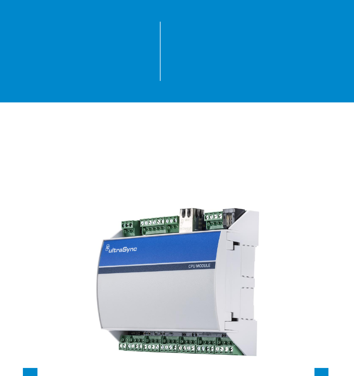
1.1 CPU
The CPU is the core component of the system and is the building block of every installation.
There are eight on-board hardwired zones that can be zone doubled to 16. Alarm reporting
and interactive services are supported by on board Ethernet connectivity. An optional cellular
module is available to provide a cellular failover path in the event of a failure of the Ethernet
connection. Additionally, a PSTN connection is available for alarm reporting. The default
reporting path is over the Ethernet connection and PSTN reporting is disabled by default.
1
REFERENCE GUIDE
UltraSync
Modular Hub

...C... 10 P/N 466-5261 • REVA • ISS 11NOV16 UltraSync Modular Hub Reference Manual ©2016 United Technologies Corporation .... .I.....
There are five on-board outputs supporting siren/speaker/strobe and smoke detector
functionality. All are programmable via Actions.
Additional capacity and functionality can be added to the system with the addition of
expansion modules via the encrypted RS-485 communication bus. Available expansion
modules include keypads, hardwired zones, wireless sensors and relay devices.
The overall sensor capacity is a combination of hardwired and wireless sensors. Wireless
sensor capacity is limited to 192. Keyfob capacity is 64 and is not affected by the number of
wireless sensors that are learned into the system.
There are multiple ways to configure the system:
• A built in web server is available for simple web browser configuration
— Local and remote access is supported
• UltraSync™ application for Android and Apple devices
• DLX 900 Upload/Download software
— Local and remote access is supported
• UM-1820E touch screen keypad
...C... 11 P/N 466-5261 • REVA • ISS 11NOV16 UltraSync Modular Hub Reference Manual ©2016 United Technologies Corporation .... .I.....
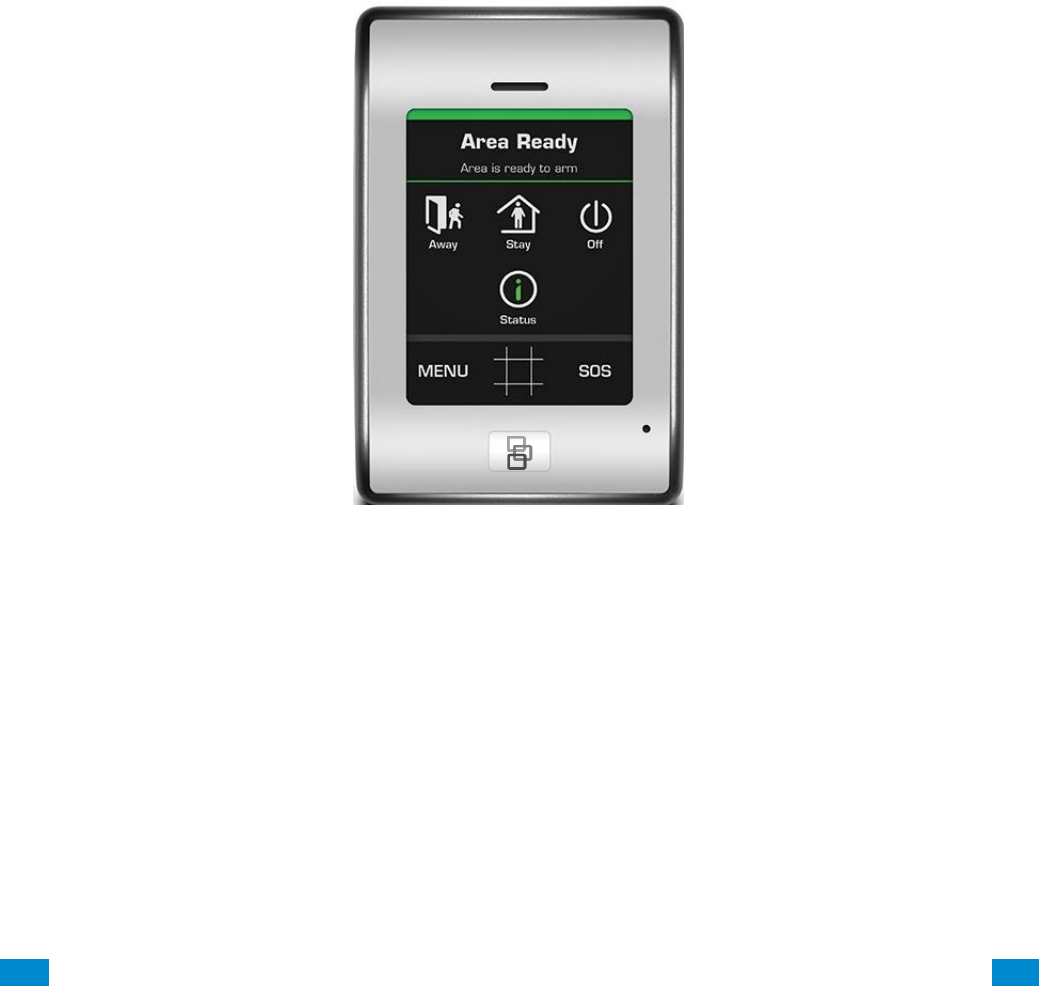
1.2 Touch Screen Keypad
The UM-1820E touch screen keypad is the primary on-premise user interface. It has an
intuitive user interface that allows the installer to fully configure the system. It also allows end
users to interact with the security system based on their assigned permission level.
...C... 12 P/N 466-5261 • REVA • ISS 11NOV16 UltraSync Modular Hub Reference Manual ©2016 United Technologies Corporation .... .I.....
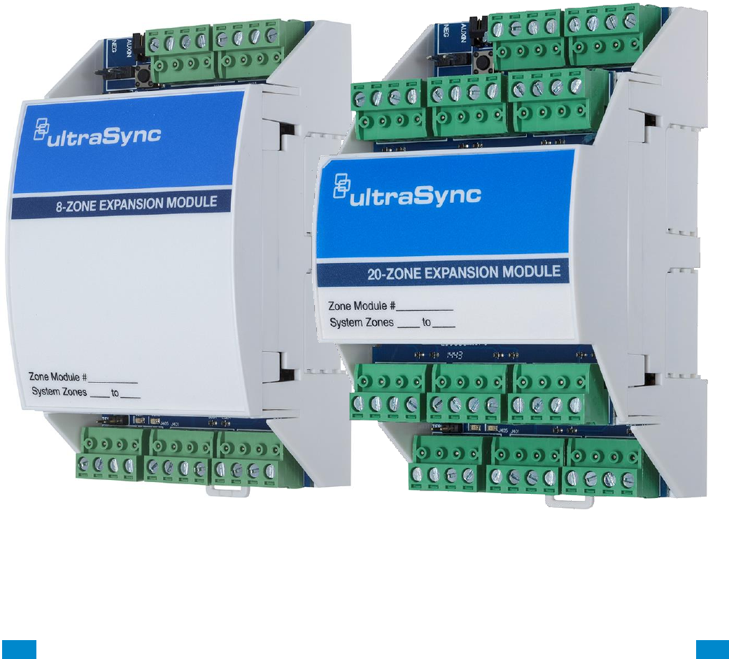
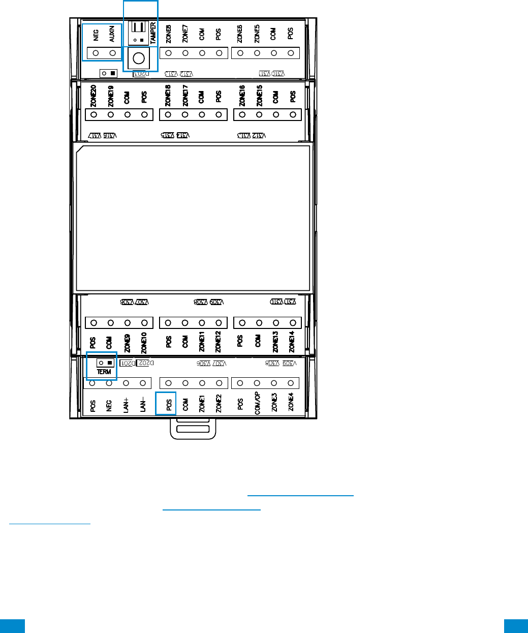
1.3 Zone Expansion Modules
Hardwired zone capacity of the system can be augmented using zone expansion modules.
Eight and 20 zone versions are available. Flexible programming options allow the installer to
maximize the efficiency of the zone expansion modules so the entire system capacity can be
utilized. For example, if only five zones are hardwired to a zone expansion module, the
system can be configured to only utilize those five zones from the module, leaving the
remaining unused zones available for the system.
...C... 13 P/N 466-5261 • REVA • ISS 11NOV16 UltraSync Modular Hub Reference Manual ©2016 United Technologies Corporation .... .I.....
Each zone expansion module must have its Zone Start and End programmed. To operate as
a smoke detector reset, see Expander Options. For details on enrolling Zone Expanders see
Enroll Function in Advanced Programming, Devices and Enrollment.
3
20 Zone Expander
1. Tamper input.
Disabled by default. Connect tamper
switch when mounted in a separate
enclosure from CPU. Enable in
\Devices\System Devices\Relay
Expanders\Expander Options.
2. Neg, Aux, not used
3. Enroll button
4. Termination jumper
5. Power available on terminals for sensors.
5
4
4
2
1
...C... 14 P/N 466-5261 • REVA • ISS 11NOV16 UltraSync Modular Hub Reference Manual ©2016 United Technologies Corporation .... .I.....
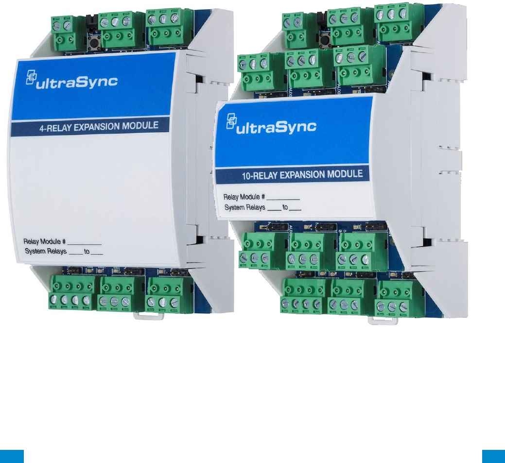
1.4 Relay Expansion Modules
Hardwired relay output capability can be added to the system using relay expansion
modules. Versions are available with 4 and 10relays. Single Pole Double Throw (SPDT)
Form C relays can be configured in 3 different modes to support different applications.
Flexible programming options allow the installer to setup manual control or automatically
control the relays. Relays can be controlled based on events including but not limited to
panel state, events (alarms, tamper, and trouble), low battery, AC, Cellular or Ethernet
failure.
Each output module adds 32 more actions to the system. Seven output modules will provide
a maximum of 256 actions.
...C... 15 P/N 466-5261 • REVA • ISS 11NOV16 UltraSync Modular Hub Reference Manual ©2016 United Technologies Corporation .... .I.....
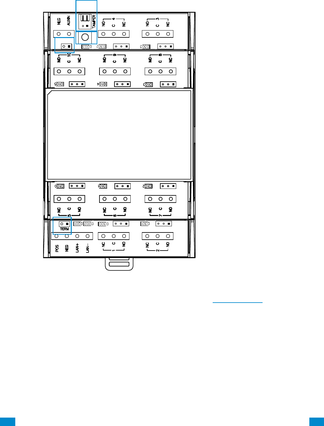
For details on enrolling Relay Output Expansion Modules, see Enroll Function in Advanced
Programming, Devices and Enrollment.
Three switching modes are available on these relays; Dry Contact and Negative or Positive
switching. For details see the relay installation sheet.
10 Relay Expander
1. Tamper input.
Disabled by default. Connect tamper
switch when mounted in a separate
enclosure from CPU. Enable in
\Devices\System Devices\Relay
Expanders\Expander Options.
2. Bus jumper
Not installed –
Relay Auxin comes from Auxin terminal.
Installed – Relay Auxin is connected to
LAN (bus) POS terminal.
3. Manual enroll button
4. Termination jumper
4
4
2
3
1
...C... 16 P/N 466-5261 • REVA • ISS 11NOV16 UltraSync Modular Hub Reference Manual ©2016 United Technologies Corporation .... .I.....
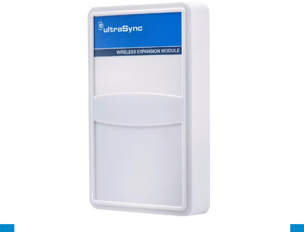
1.5 Wireless Expansion Modules
Wireless sensor capability of the system is added via the wireless sensor expansion module.
In addition to providing wireless sensor capability to the system, the wireless expansion
module also can provide support for two hardwired zones and one relay.
Up to192 wireless sensors and 64 keyfobs are supported. Multiple wireless sensor
expansion modules can be enrolled into the system to improve wireless reception
performance; however, the overall wireless sensor capacity is not increased. Each sensor is
learned into the CPU, not the module, greatly simplifying the installation process and
improving overall system performance when multiple wireless expansion modules are
installed:
• With two wireless expansion modules installed in close proximity to each other,
redundancy is automatically built into the system (e.g. if one wireless receiver fails, the other
will continue to receive wireless sensor transmissions).
• If a large coverage area is desired, multiple wireless expansion modules can be distributed
throughout the area for expanded coverage purposes.
Wireless sensors will be received by multiple wireless expansion modules, providing a
receive “diversity” benefit in a changing wireless environment. The CPU will process all
sensor transmissions received from each wireless expansion module providing wireless
sensors multiple reception paths to improve reliability and performance.
...C... 17 P/N 466-5261 • REVA • ISS 11NOV16 UltraSync Modular Hub Reference Manual ©2016 United Technologies Corporation .... .I.....
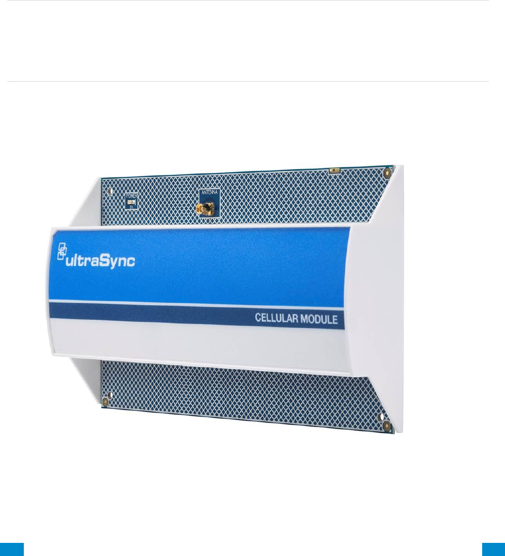
1.6 Cellular Module
An optional cellular radio module provides a backup communication path over a cellular
network if the Ethernet or PSTN connection fails. This provides a plug and play connection
with no configuration needed in most cases. The only requirement is good cellular reception.
To connect via cellular service, you only need to install the cellular radio module and
provision the panel for cellular service grade reporting in the UltraSync portal.
For details see the cellular module installation sheet.
Note: The cellular module is not a bus connected device. It installs directly to the CPU.
Caution: Electrostatic discharge may cause damage and void the warranty. Proper ESD
precautions must be used during installation. Remove all power (AC and battery) to the CPU
before proceeding. Failing to do so could result in possible damage to the product. System
components should be kept in the antistatic packaging when not in use.
...C... 18 P/N 466-5261 • REVA • ISS 11NOV16 UltraSync Modular Hub Reference Manual ©2016 United Technologies Corporation .... .I.....
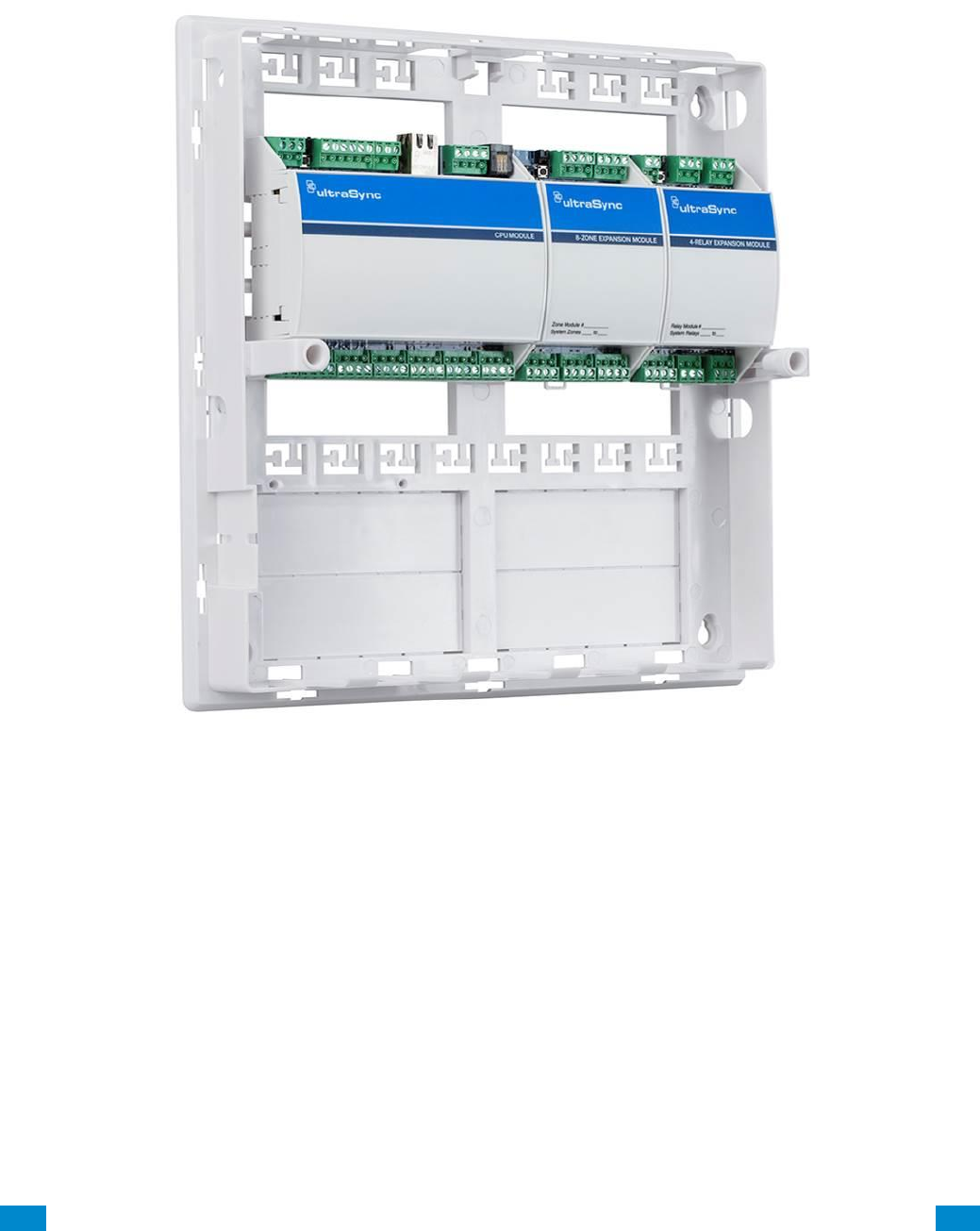
1.7 Residential Plastic Enclosure
The plastic enclosure features a DIN rail for mounting modules, a tamper switch, and
integrated cable management.
The lid can be removed by releasing the two screws using the supplied Allen key.
The enclosure should be installed indoors under the following operating conditions:
• Temperature range: +14°F to 131°F (-10 to +55°C)
• Humidity range: Average 95% relative humidity, non-condensing
...C... 19 P/N 466-5261 • REVA • ISS 11NOV16 UltraSync Modular Hub Reference Manual ©2016 United Technologies Corporation .... .I.....
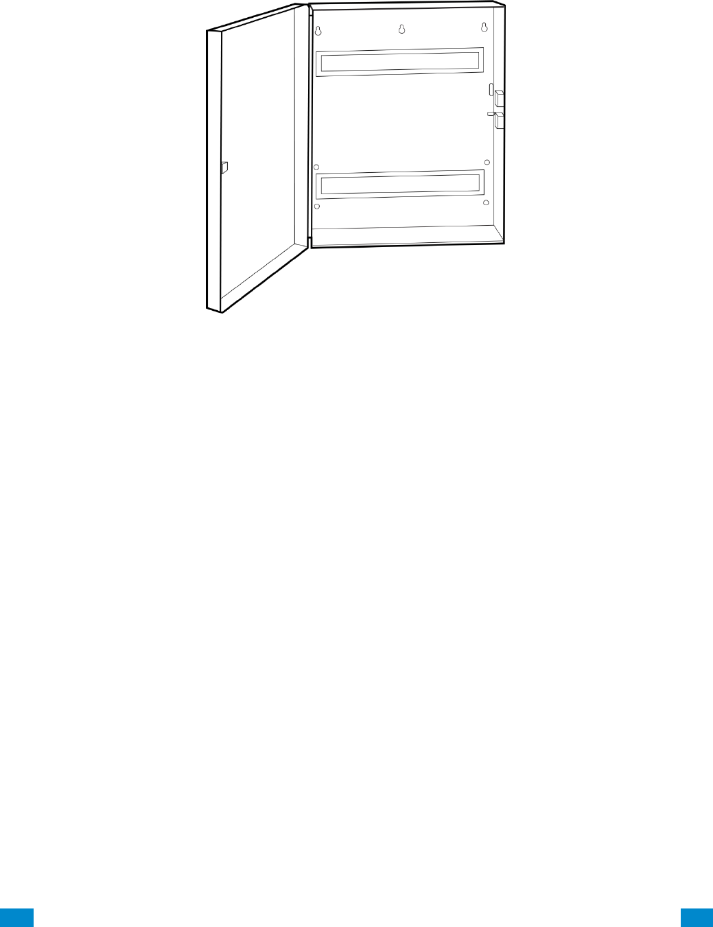
1.8 Commercial Metal Enclosure
A metal enclosure is available for commercial applications, installations where additional
zone and/or output expansion modules are required or situations where a larger backup
battery is required. The UM-CME metal enclosure includes a tamper switch and two metal
DIN rails.
The enclosure should be installed indoors under the following operating conditions:
• Temperature range: +14°F to 131°F (-10 to +55°C)
• Humidity range: Average 95% relative humidity, non-condensing
...C... 20 P/N 466-5261 • REVA • ISS 11NOV16 UltraSync Modular Hub Reference Manual ©2016 United Technologies Corporation .... .I.....
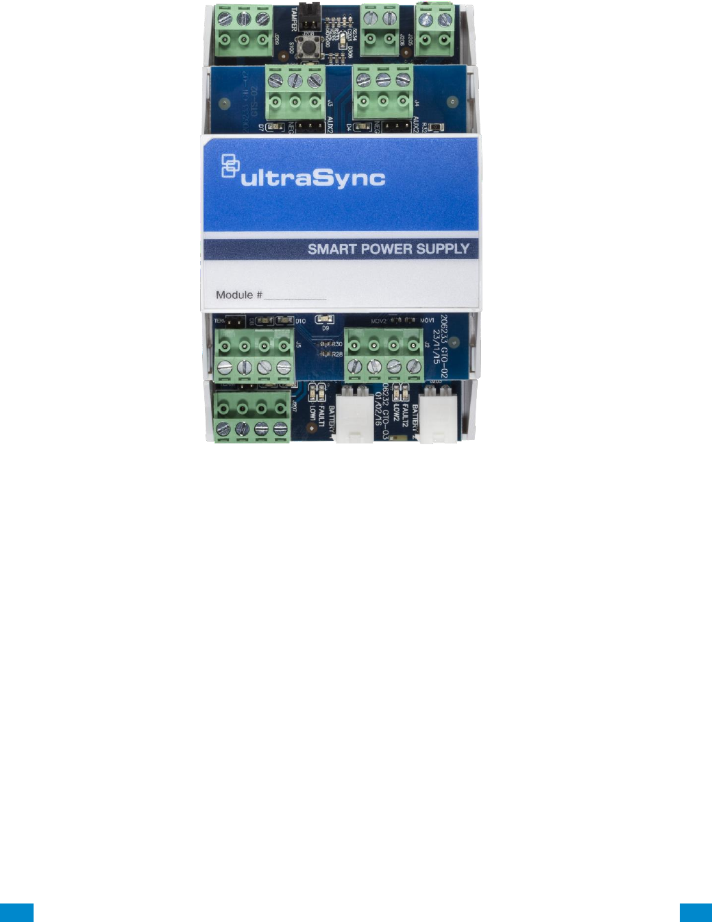
1.9 Smart Power Supply
The UM-SPS smart power supply provides additional battery and current capacity to
UltraSync Modular Hub installations. The smart power supply also offers two zone inputs
and two programmable SPDT relay outputs. The module has a tamper connector that can be
used to supervise the enclosure in which it is mounted. Both the main power input and
batteries are monitored. The module provides the option to extend the RS-485 bus length up
to an additional 2,600 ft. (800m). The extended RS-485 bus is optically isolated in this
configuration.
Up to 8 smart power supplies can be used per system. One smart power supply can be used
on each bus segment in a star configuration. The UM-SPS does not support a cascaded
architecture of multiple units in a daisy chain configuration.
Power Outputs
The smart power supply has three auxiliary power outputs to power three separate bus
segments. The available current on each output is determined by the number of batteries
that are connected to the unit. See below for details.

...C... 21 P/N 466-5261 • REVA • ISS 11NOV16 UltraSync Modular Hub Reference Manual ©2016 United Technologies Corporation .... .I.....
Battery Connection
1. The smart power supply supports one or two battery configurations. If additional battery
backup capacity is required, a second battery can be installed. Up to two 17.2 AH
batteries can be connected to the unit.
2. Install batteries before connecting power.
3. Connect a single battery to the Battery 1 input.
4. If a second battery is required, connect it to the Battery 2 input.
Battery 2 becomes enabled once the battery test passes. A battery test will occur when
power is connected to the smart power supply, daily battery test, or when a user manually
activates a battery test. See keypad manual for instructions on performing a manual battery
test.
Connect Transformer and Tamper
1. A 16.5 VAC/40 VA transformer (recommended Interlogix PN 600-1023 or 600-1023-CN)
must be utilized with the unit. Connect the transformer secondary voltage (16.5 – 18.0
VAC) to the smart power supply AC/DC IN connection.
2. If enclosure tamper monitoring is required, connect the tamper switch of the housing to
the TAMPER input. You must enable tamper monitoring on the smart power supply in the
device expander options menu (tamper monitoring is disabled by default).
Over Current Protection
The smart power supply provides over current monitoring and protection. When more current
is drawn from the power supply than the transformer can provide, the device will send an
“Over Current” message to the Modular Hub CPU. The transformer is disconnected within 10
seconds of the over current condition event.
Operation continues on battery supply until the condition is removed, or batteries are
exhausted.
LAN Wiring and Topology
The UM-SPS smart power supply can be used as power supply unit or as a bus
extension/isolator. Depending in which mode the unit is applied in the field, a different RS-
485 LAN wiring is required.
In power supply mode (option 1), only the LAN connection terminal on the bottom board of
the UM-SPS is used. Wire this terminal to the Modular Hub CPU.
See diagram Wiring Option 1.
In bus extension/isolator mode (option 2), the xGen panel LAN needs to be wired to the
ISOLATED LAN terminal on the top board of the UM-SPS. Any bus device wired to the LAN
connection terminal on the bottom board is now optically isolated.
See diagram Wiring Option 2.
...C... 22 P/N 466-5261 • REVA • ISS 11NOV16 UltraSync Modular Hub Reference Manual ©2016 United Technologies Corporation .... .I.....
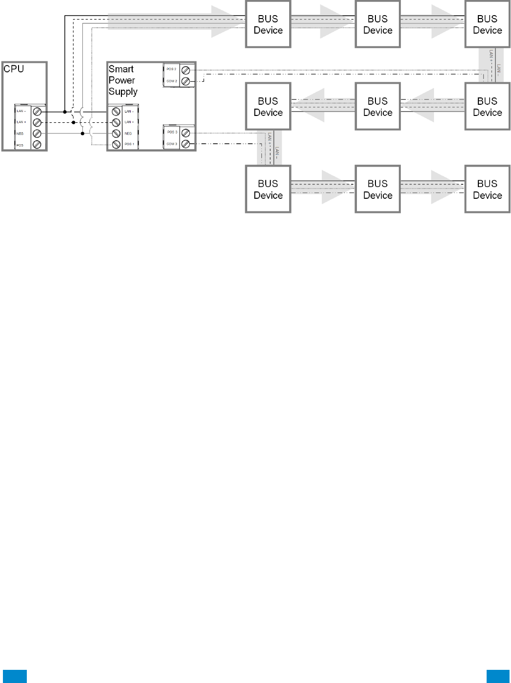
Option 1 – Power supply mode, no bus isolation
This option provides additional power to connect more devices.
1. Connect a 40 VA 16.5 VAC transformer to the smart power supply.
2. DO NOT connect CPU POS to the Smart Power Supply POS 1 terminal.
3. Connect the CPU NEG, LAN+ and LAN- to the UM-SPS smart power supply’s NEG,
LAN+ and LAN- terminal located on the bottom board. This provides data communication
and a common ground.
4. Use POS1/NEG, COM2/POS2 and COM3/POS3 to power additional devices.
5. DO NOT use the ISOLATED LAN terminal located on the top board (POS B, NEG B,
LAN B+, and LAN B-).
6. In this configuration, multiple smart power supplies can be cascaded to form a long daisy
chain configuration.
7. It is recommended to utilize this configuration when multiple smart power supplies need
to be cascaded to form a long daisy chain topology.
...C... 23 P/N 466-5261 • REVA • ISS 11NOV16 UltraSync Modular Hub Reference Manual ©2016 United Technologies Corporation .... .I.....
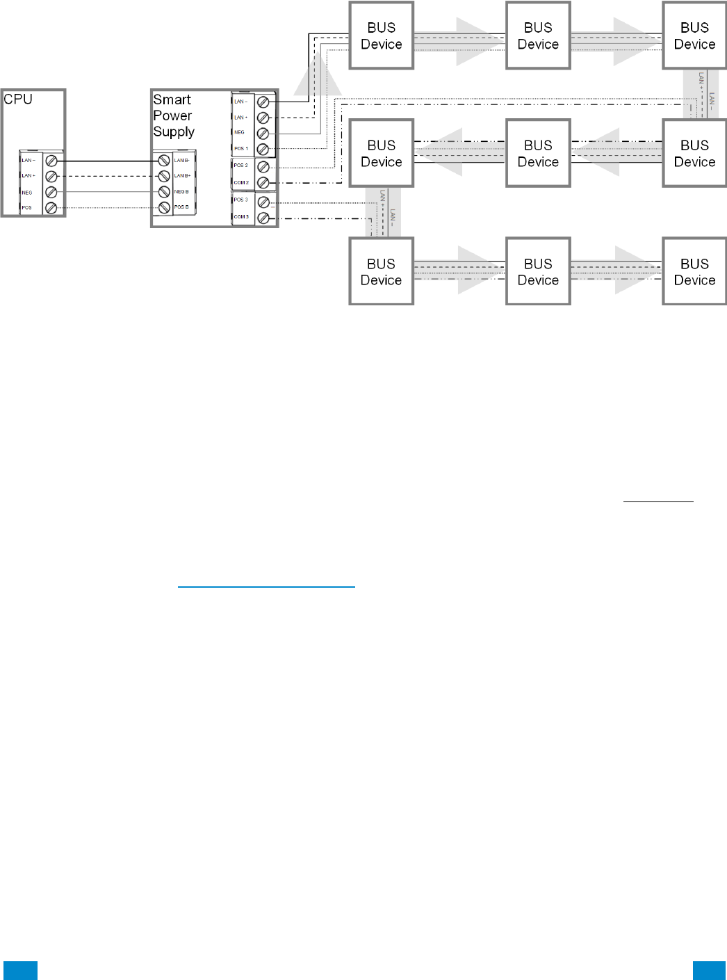
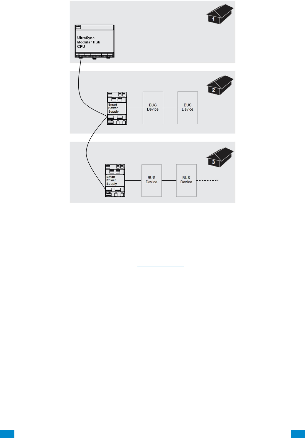
Option 2 – Extension/isolator mode
For larger sites requiring longer cable runs and/or more power, up to eight UM-SPS smart
power supplies can be added.
This topology provides additional power and an optically isolated LAN bus between the
Modular Hub CPU and each UM-SPS smart power supply. This is useful for connecting the
bus between buildings which may require electrical isolation and/or optical isolation to avoid
ground loops.
1. Connect the CPU terminals POS, NEG, LAN+ and LAN- to the Smart Power Supply
ISOLATED LAN terminal POS B, NEG B, LAN B+, and LAN B-, located on the top board.
The CPU will power the smart power supply's isolated LAN B+ and LAN B- terminals.
2. Do not connect the EARTH terminal on the Smart Power Supply to EARTH terminal on
the CPU if you require electrical isolation. Follow the guidelines contained in Section 2.2
for connecting the EARTH ground terminal.
3. Use POS1/NEG, COM2/POS2 and COM3/POS3 to power additional devices.
4. USE LAN + and LAN – to connect additional devices on the isolated bus.
5. In this configuration, multiple smart power supplies can NOT be cascaded to form a long
daisy chain configuration.
6. It is recommended to utilize the optical isolation mode in most situations as it also
isolates bus noise generated on one bus segment from transferring to other bus
segments.
7. See below for typical topology in this configuration.
...C... 24 P/N 466-5261 • REVA • ISS 11NOV16 UltraSync Modular Hub Reference Manual ©2016 United Technologies Corporation .... .I.....
Connect Relay Outputs
Two relay outputs are available on the smart power supply which can be programmed to
activate when certain actions occur on the system. See how to program power supplies in
Advanced Programming, System Devices Section 6.9.1.5.
...C... 25 P/N 466-5261 • REVA • ISS 11NOV16 UltraSync Modular Hub Reference Manual ©2016 United Technologies Corporation .... .I.....
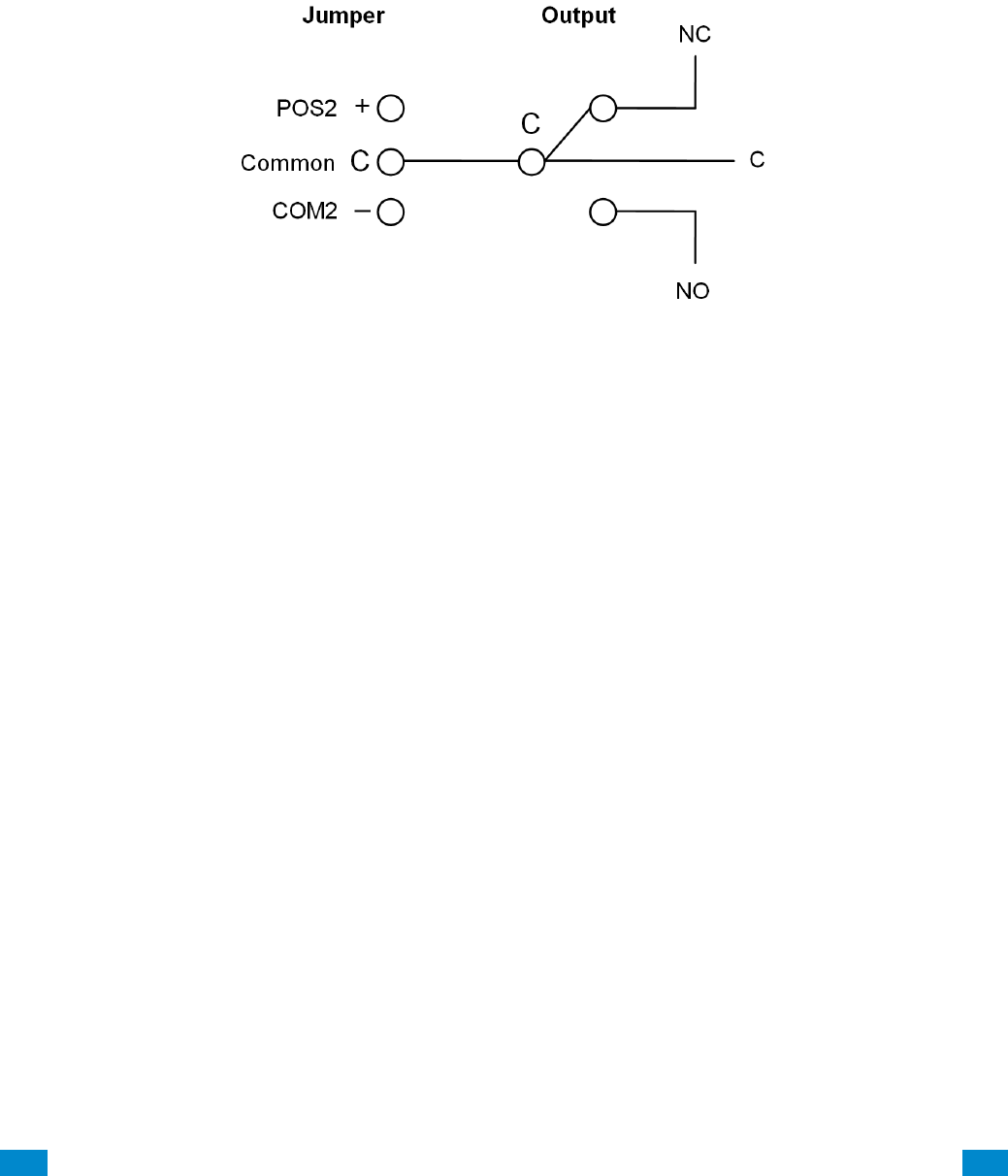
Relay Modes
The two Single Pole Double Throw (SPDT) Form C relays can be configured in 3 different
modes to support different applications.
The relays are connected to the output terminals with Normally Open and Normally Closed
connections for your convenience.
Use the jumper next to the relay to select the mode suitable to your requirements.
Default is no jumper with relay in NC position.
Red LEDs light up when the respective relay is energized.
No Jumper
Dry contact closure provided to output terminal.
Maximum Load 30 VAC @ 0.5 A or 24 VDC @ 1 A.
Jumper between C and COM2
Smart power supply common connection provided to output terminal @ typical 0 V. Do not
exceed relay rating which is maximum load 30 VAC @ 0.5 A or 24 VDC @ 1 A.
Jumper between POS2 and C
Smart power supply voltage provided to output terminal @ typical 12-13 VDC.
Do not exceed relay rating.

...C... 26 P/N 466-5261 • REVA • ISS 11NOV16 UltraSync Modular Hub Reference Manual ©2016 United Technologies Corporation .... .I.....
1.10 Batteries
A lead acid rechargeable battery must be installed in the system to provide power in the
event of main AC power failure. Several options are available as detailed in the table below.
Select the appropriate battery based on your system configuration and required battery
backup time. See specification section S.4 for battery backup calculation details. Maximum
battery capacity connected to the CPU is 12 Amp Hours.
Battery Options
Part Number
Capacity
60-681
4 Amp Hours
60-680
7 Amp Hours
Warning:
Make sure batteries are stored and worked on in a well ventilated area. ALWAYS wear
approved safety glasses and face shield or splash proof goggles when working on or near
batteries:
Always wear proper eye, face and hand protection.
Keep all sparks, flames and cigarettes away from the battery.
Never try to open a battery with non-removable vents.
Make sure work area is well ventilated.
Exercise caution when working with metallic tools or conductors to prevent short circuits
and sparks.
Always read and follow all precautionary labels on the product.
1.11 Transformer
A 16.5 VAC transformer is used to power the system. Select the appropriate transformer
from the options shown in the table below.
Transformer Options
Part Number
Description
600-1023
Class 2 Transformer, 16.5V, 40VA
600-1023-CN
Class 2 Transformer, 16.5V, 40VA (Canada)

...C... 27 P/N 466-5261 • REVA • ISS 11NOV16 UltraSync Modular Hub Reference Manual ©2016 United Technologies Corporation .... .I.....
2 Hardware Installation
Minimum System Requirements
CPU
Enclosure
Power Supply/Transformer
Keypad
Siren/Speaker
Battery
Choose a Location
When choosing a location for the system components, there are a number of appliances and
areas to avoid which could interfere with the system.
Choose a location that optimizes signal strength (319.5, Z-Wave, Cellular)
Avoid TV and other electronic appliances
Avoid microwave ovens
Avoid wet and moist areas such as bathrooms and kitchens
Avoid cordless telephones
Avoid computers and other wireless equipment
Do not run bus wiring any closer than 6 inches to an AC or other communication lines.
When crossing other lines, always run perpendicular
2.1 Power Requirements
The UltraSync Modular Hub is designed to be used with a 16.5 VAC transformer.
Alternatively, an 18-26 VDC source can be utilized to power the system.
2
REFERENCE GUIDE
UltraSync
Modular Hub
...C... 28 P/N 466-5261 • REVA • ISS 11NOV16 UltraSync Modular Hub Reference Manual ©2016 United Technologies Corporation .... .I.....
2.2 Grounding
The CPU’s Earth terminal must be earth grounded for lightning protection to work effectively.
The terminal should be tied to a verified cold water pipe or a dedicated, grounded copper rod
6’ to 10’ long. Use 16 gauge wire.
2.3 Shielding
If shielded cable is used, the shielding of all cables should only be connected on one end of
the cable to one common grounding point in a building. If a shielded LAN cable is routed via
more than one plastic device, the shielding from incoming and outgoing cables must be
connected (e.g. multiple plastic enclosures that are daisy chained together).
2.4 Termination Jumpers
Correct RS-485 termination reduces communication issues with signal reflections.
For a single long cable run, put a jumper across the terminal labeled TERM on the CPU and
the furthest bus device.
For installations with multiple long cable runs, (star configurations) do not place a terminator
on the CPU; rather place one at the end of each of the two longest cable runs.
Where the keypad is the last bus device, use the terminal labeled S202.
2.5 Cable Requirements
The system’s RS-485 communication bus is used to connect keypads and other devices to
the CPU.
• 2 pair twisted, 22 AWG cable is recommended.
Minimum 4 twists per foot
Less than 16 pF per foot
Characteristic impedance of 100 to 120 ohms
The system’s screw terminals support 30-16 AWG wire
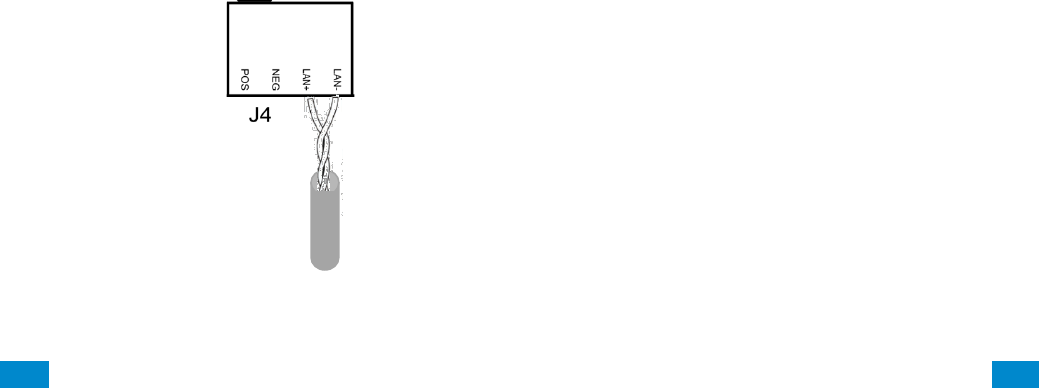
The individual wires comprising the twisted pair must be connected to the LAN+ and LAN-
terminals to receive the noise immunity benefits of twisted pair cable. See figure below. Do
not combine the individual wires of the twisted pair to increase the effective wire gauge of
the cable run.
...C... 29 P/N 466-5261 • REVA • ISS 11NOV16 UltraSync Modular Hub Reference Manual ©2016 United Technologies Corporation .... .I.....
• Maximum RS-485 bus length is 2,600 ft. (800 m) when run as a single serial cable run. If a
star configuration is utilized, the maximum total bus length may be reduced substantially
depending on the number of branches, the length of the branches and a multitude of other
factors. It is recommended to reduce the number of branches and the cable length when
utilizing a star configuration.
• Device maximum: 64 bus devices.
• A separate power supply may be required for long cable runs with multiple devices due to
voltage drop on the bus wire. If a device is powered with a separate power supply, do not
connect “POS” from the CPU. Connect “+” of the local power supply to “POS” on the
device, and connect 0 volts from the power supply and NEG from the CPU to the keypad
terminal marked “NEG−”.
See Appendix A.14 Calculating Maximum Bus Cable Length, for more details on determining
when an additional power supply is required.
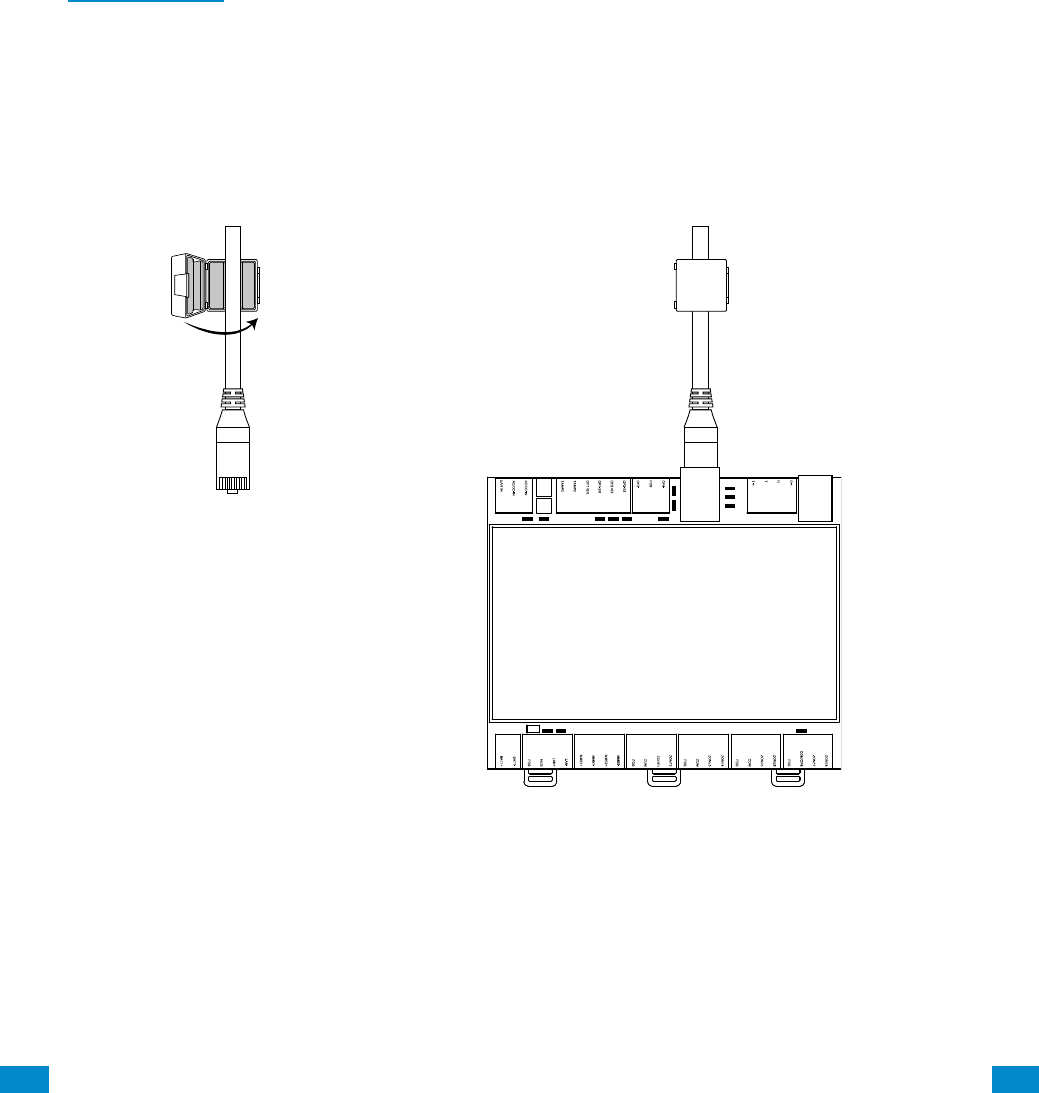
2.6 Ferrite Installation
Install the supplied ferrite on the Ethernet cable before attaching the cable to the intrusion panel.

...C... 32 P/N 466-5261 • REVA • ISS 11NOV16 UltraSync Modular Hub Reference Manual ©2016 United Technologies Corporation .... .I.....
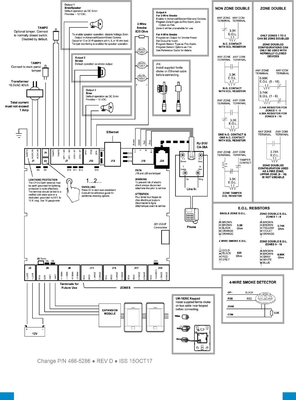
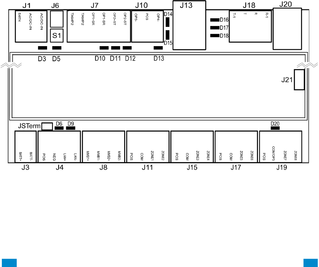
2.8 Terminal Diagram
• J1 – Terminals for power inputs
• J6 – Box Tamper (disabled by default)
• S1 – Enrollment button: Hold button down for 3s to activate automatic device enrollment
feature; Holding the button down while powering up resets the Installer user type
to a Master Installer user type.
• J7 – Terminals for Tamper 2 (disabled by default), Output 1 (Siren) and Output 2 (Strobe)
• J10 – Terminals for Output 3 (Siren) and Output 4 (2 and 4 wire smoke)
• J13 – RJ45 socket for Ethernet (IP/LAN) connection
• J18 – Terminals for telephone line, bridged to J20
• J20 – RJ11 6P4C socket for telephone line, bridged to J18 output. This connector is
accessible after removing the plastic cover on the top of the CPU housing.
• J21 – 5-pin connector for USBUP device. This connector is accessible after
removing the plastic cover on the side of the CPU housing. USBUP device can be
used to update firmware or CPU configuration.
• J3 – Terminals for backup battery
• J4 – Terminals for RS-485 bus and auxiliary power connection
• J8 – Terminals for future use
• J11 – Terminals for Zone 1 and 2
• J15 – Terminals for Zone 3 and 4
• J17 – Terminals for Zone 5 and 6
• J19 – Terminals for Zone 7 and 8. Common terminal shared with output 5 (output 5
disabled by default)
...C... 33 P/N 466-5261 • REVA • ISS 11NOV16 UltraSync Modular Hub Reference Manual ©2016 United Technologies Corporation .... .I.....
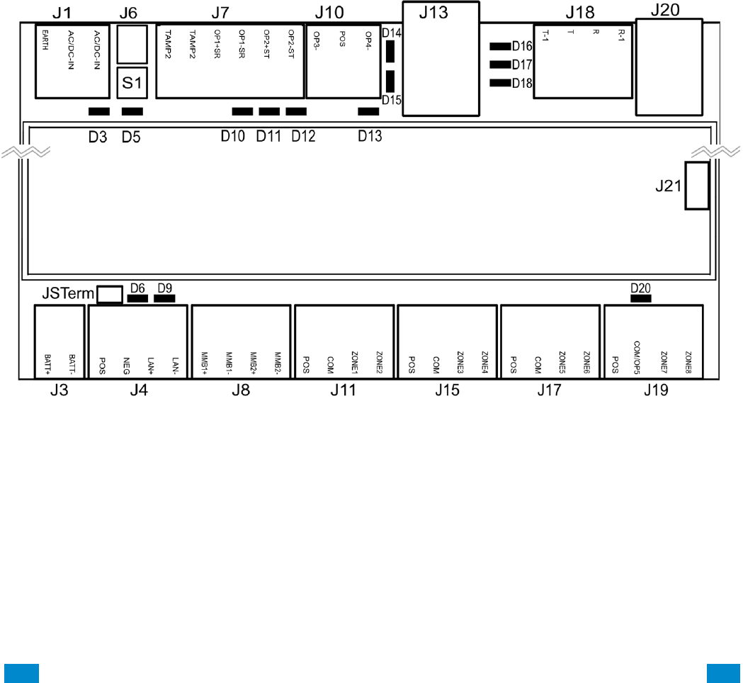
2.9 LED Diagram
• D3 – Red LED: 5 V internal power present
• D5 – Red LED:
• Enrollment mode active, slow flash means Automatic enrollment, fast flash means
Manual enrollment
• During a default it will toggle during each menu default
• When communicating over the phone line it will turn on when a valid handshake
tone or kiss off tone is present
• During a phone session it will turn on when a DTMF digit is detected
• D10 – Red LED: follows Output 1 (BELL output), typically used for indoor speaker
• D11 – Red LED: follows Output 2 (Strobe)
• D12 – Red LED: follows Output 3 (Outdoor Siren)
• D13 – Red LED: follows Output 4 (Power)
• D14 – Red LED: Ethernet Link Present
• D15 – Green LED: Ethernet Activity
• D16 – Green LED: UltraSync Ethernet Link Present
• D17 – Green LED: UltraSync Cellular Link Present
• D18 – Red LED: Heartbeat, should flash every second
• D6 – Red LED: RS485 Transmitting
• D9 – Green LED: RS485 Receiving
• D20 – Red LED: follows Output 5 (Power)

...C... 34 P/N 466-5261 • REVA • ISS 11NOV16 UltraSync Modular Hub Reference Manual ©2016 United Technologies Corporation .... .I.....
3 Programming Methods
Once your hardware has been installed, there are four (4) ways to program your system.
1) Onboard Web Server
2) UltraSync Application
3) DLX 900
4) On-site keypad
Programming includes such tasks as enrolling bus devices, configuring the operation of the
security system, adding IP cameras and Z-Wave devices.
It is required to first have a UM-1820E touchscreen keypad enrolled in the system before
proceeding. Before any bus devices are connected to the CPU, connect a single UM-1820E
to the bus and power up the system. To automatically enroll the keypad, push the ENROLL
button on the CPU until the LED begins to flash indicating that the automatic enrollment
process has been initiated.
On Board Web Server – The recommended method, this allows access to all programming
menus from the built-in web server using a PC or smart device without the need to install
any software. Local and remote access is supported. Remote access requires UltraSync
Portal login credentials. Before you can utilize the local method, you will be required to
retrieve the IP address of the CPU. Please see Section 3.1.2 of this document for retrieving
the IP address.
UltraSync App – This provides access to the Hub via a smart device running the UltraSync
application. The screens and menus in the UltraSync application are similar to the Web
Server screens. Before you can utilize the UltraSync App, you will have to enable this
functionality in the CPU by programming the Web Access Passcode. This can be
accomplish via the UM-1820E touch screen keypad or the on board web server. Please see
Section 3.2 for additional details.
DLX 900 Upload/Download Management Software – An alternative way to program your
system from a PC. Before you can utilize DLX 900, you will have to enable this functionality
in the CPU by programming the Download Access Code. This can be accomplish via the
UM-1820E touch screen keypad or the on board web server. Please see Section 3.3 for
additional details.
On-site Keypad – The UM-1820E touchscreen offers a programming menu allowing full
system configuration. Refer to the installation manual.
3
REFERENCE GUIDE
UltraSync
Modular Hub

...C... 35 P/N 466-5261 • REVA • ISS 11NOV16 UltraSync Modular Hub Reference Manual ©2016 United Technologies Corporation .... .I.....
3.1 Programming via Web Server
This system has a built in web server which makes it easy and simple to set up your system
from a web browser instead of the keypad.
Access to the Web Server is available locally when the computer or smart device is
connected to the same LAN that the CPU is connected to. The Web Server is also available
from remote locations when logged into the UltraSync portal.
3.1.1 Connect to LAN
The CPU is shipped to automatically receive its IP address from the local router. Simply
connect the CPU to the local router via the Ethernet cable then turn on the power to your
system. It will take approximately 10 seconds for the local router to assign the system an
IP address.
3.1.2 Retrieve the CPU IP address
Retrieve the system’s IP address via the keypad.
From the UM-1820E press:
Menu – Program – ▼– Communicator – IP Configuration – IP Address
Write down the IP address of the CPU.
In the unlikely event that the router is not configured to automatically assign an IP
Address, you will have to manually program an IP address for the system. Instructions to
manually assign the network settings follows in section 3.1.3 below.
3.1.3 Manually Assign an IP Address
If you are unable to get an IP address from the router automatically, then your router may
not be configured to automatically assign an IP address (via DHCP) or certain security
settings may be enabled. Contact the router’s network administrator for assistance and
the assignment of the network settings for the CPU.
1. Turn DHCP off on the CPU.
On the keypad press:
Menu – Program – – Communicator – IP Configuration – – – IP Options –
Enable DHCP. The display should show “N” to indicate that DHCP is disabled.
2. Manually assign network settings
a. Press Menu – Program – – Communicator – IP Configuration
b. Assign the following values that were provided by the network administrator:
1. IP Host Name (optional)
2. IP Address
3. Gateway
4. Subnet
5. Primary DNS
6. Secondary DNS (optional)
3. Connect your computer or smart device to the same router that the system is connected
to. This connection to the router can be via Ethernet or Wi-Fi. Open your web browser
on the device. If DHCP has been disabled in the router, you will have to manually
...C... 36 P/N 466-5261 • REVA • ISS 11NOV16 UltraSync Modular Hub Reference Manual ©2016 United Technologies Corporation .... .I.....
assign an IP address/network settings to your computer or smart device. Consult with
the network administrator if required.
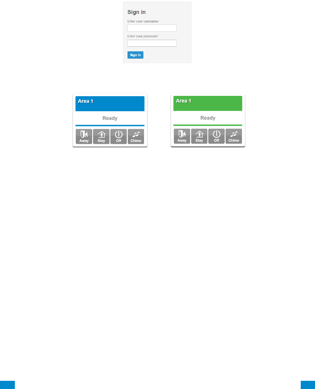
3.1.4 Login to the Web Server
4. Enter the IP address of the CPU into a web browser. The login screen shown below
should appear. Some browsers may require you to enter http:// plus the system’s IP
address.
Enter your username and password. By default this is: installer and 9–7–1–3.
You should now see a screen similar to one of the below:
Your system is now successfully connected to your Ethernet network.
Press Settings or Advanced to program your system.
3.1.5 Troubleshooting LAN Connections
• Check your router settings and try again.
• On the Touch Screen keypad press Menu – [PIN] – [ENTER] – Program –
Communicator – IP Configuration – IP Options, this will allow you to modify
connection settings including DHCP.
• If the panel is connected to a local router which provides internet access, open up a
web browser on your computer or smart device and verify that you have internet access
(make sure cellular service is disabled on cellular enabled devices such as tablets and
smart phones when connecting over the LAN).
3.2 Programming via UltraSync
UltraSync is an app that allows cloud-based remote management and remote access to the
system from an Apple® iPhone/iPad, or Google Android device.
Download the UltraSync app. Carrier charges may apply and an Apple iTunes or Google
account is required.
3.2.1 Set Up a Web Access Passcode for UltraSync
For security, remote access via the UltraSync app is disabled by default. Follow these
steps to enable it:
Select Settings - Network from the Web Server. Enable remote access for the UltraSync
app by changing the Web Access Passcode (WAP). This is an eight digit code that
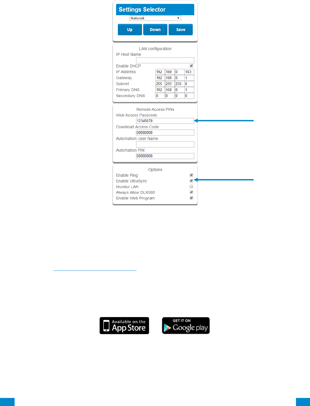
...C... 37 P/N 466-5261 • REVA • ISS 11NOV16 UltraSync Modular Hub Reference Manual ©2016 United Technologies Corporation .... .I.....
permits access from the UltraSync application. The default Web Access Passcode of
00000000 prevents remote access.
Enter a Web Access Passcode.
Press Save.
Follow this sequence to program the Web Access Passcode using the keypad:
Menu – PIN – Enter – Program – Network Servers – Web Access Passcode
For a detailed explanation of the function of the Web Access Passcode please see
Section 5.6, Programming the Network.
3.2.2 Connect via UltraSync Application
On Apple® devices go to the App Store™. On Android devices go to the Google Play™
store.
Search for UltraSync.
Install the app.
Press the icon on your device to launch it.
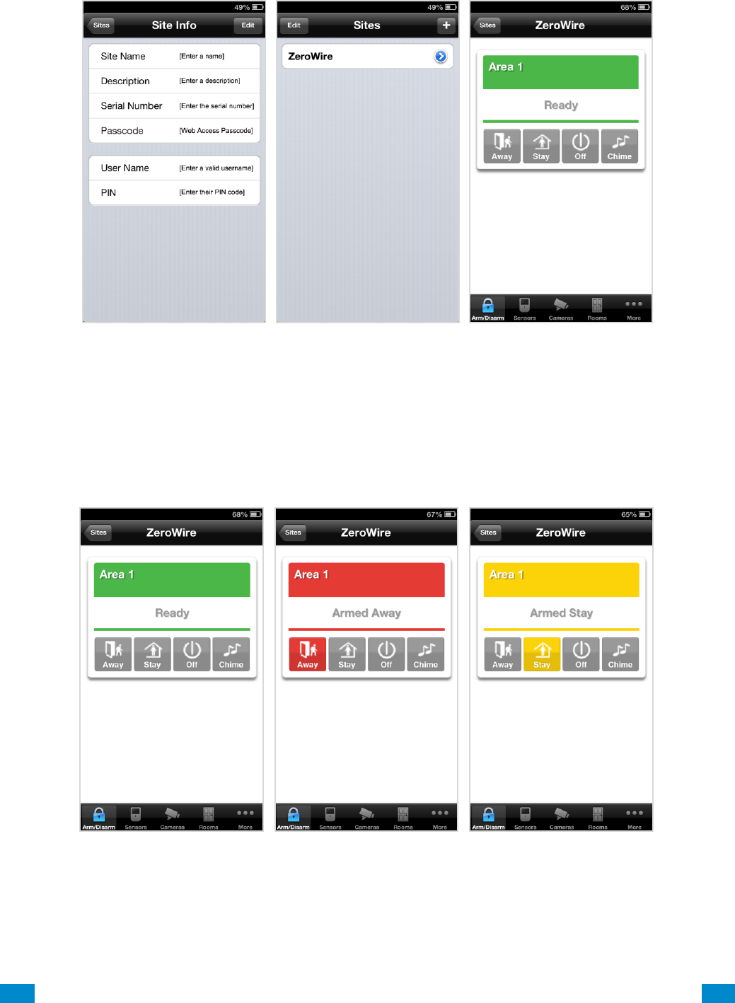
Press + on the top right to add a new site, or the blue arrow to edit an existing site.
Enter the details of the security system.
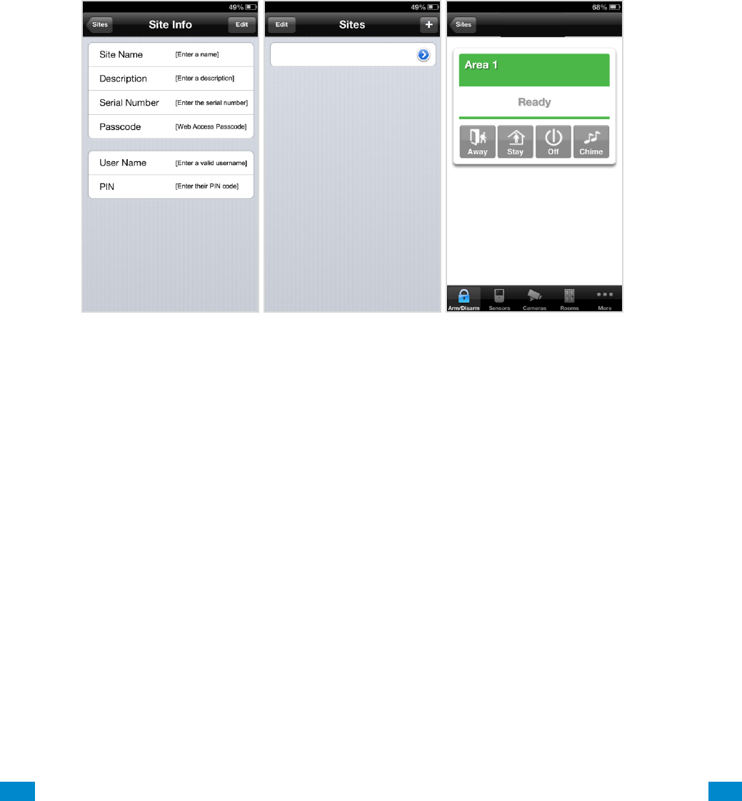
...C... 38 P/N 466-5261 • REVA • ISS 11NOV16 UltraSync Modular Hub Reference Manual ©2016 United Technologies Corporation .... .I.....
The serial number is printed on the back of the panel. Alternatively login to the Web
Server and go to Settings – Details to view it. You can also retrieve the serial number from
the keypad. On the Touch Screen keypad press Menu – [PIN] – [ENTER] – Program –
System – Status – Device Serial.
The default username and PIN code for the installer is: installer and 9–7–1–3. The default
username and PIN code for User 1, the Master User is User 1 and 1–2–3–4. You may
also use any other valid user account. Users will only see and have access to menus at
their permission level.
Press the Done button to save the details, then Sites to go back.
Press the name of the Site; the app will now connect you to your system.
...C... 39 P/N 466-5261 • REVA • ISS 11NOV16 UltraSync Modular Hub Reference Manual ©2016 United Technologies Corporation .... .I.....
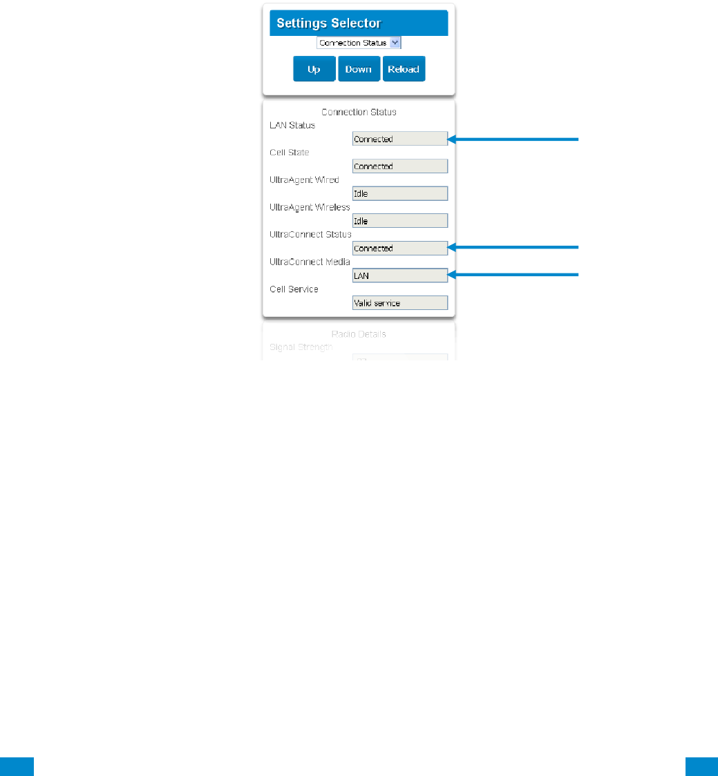
3.2.3 Check LAN Connection to UltraSync Servers
1. Login to the UltraSync Web Server as shown above
2. Click Settings
3. Select Connection Status in the drop down menu
4. Check:
• LAN Status should display Connected.
• UltraSync Status should display Connected.
• UltraSync Media should display LAN.
If it does not: Check cable connection and router settings.
...C... 40 P/N 466-5261 • REVA • ISS 11NOV16 UltraSync Modular Hub Reference Manual ©2016 United Technologies Corporation .... .I.....
3.2.4 Troubleshooting UltraSync Setup
1.
UltraSync Site Creation fails
Cause
Solution
Settings are entered incorrectly
Check the serial number, web access passcode, user
name and PIN codes match those in the system.
Web Access Passcode must not be 00000000.
User Name must be entered with a space between the
first and last name and with correct capitalization.
2.
Cannot see local Wi Fi access point from smartphone
Cause
Solution
Some hotspot access points may not accept
802.11g connections.
Ensure your Wi Fi access point is able to accept
802.11b or 802.11g.
3.
Network connections fail
Cause
Solution
Ethernet not working
If connected by Ethernet, check that the cable is plugged
in and the connection is working.
Network not set
Check Settings – Network – Enable UltraSync is
checked.
4.
Cannot get IP address
Cause
Solution
The wireless/router may not be configured for
automatic DHCP or certain security settings may be
enabled.
Check with the router’s network administrator and
configure the system as required.
5.
Cannot access internet
Cause
Solution
Mobile device has no access
Open a web browser on your mobile device to double
check access.
Try disabling Wi Fi on your device once the system is
configured and using the 3G/4G data connection of your
device with the UltraSync app.
6.
Server connections fail
Cause
Solution
Server addresses are incorrect
Check the UltraSync servers are correct. See
Advanced Programming, Network Servers for reference.
a. Ethernet Server 1 - zw1.UltraSync.com:443
b. Ethernet Server 2 - zw1.UltraSync Modular
Hub.com:443
c. Wireless Server 1 - zw1w.UltraSync.com:8081
d. Wireless Server 2 - zw1w.UltraSync Modular
Hub.com:8081
7.
Configuration setting changes fail
Cause
Solution
Devices are not responding to inputs
Re-initialize equipment. Power cycle connected
equipment including customer supplied router(s).

...C... 41 P/N 466-5261 • REVA • ISS 11NOV16 UltraSync Modular Hub Reference Manual ©2016 United Technologies Corporation .... .I.....
3.3 Programming via DLX 900 Management Software
Another method to manage your system is to use the DLX 900 up/download software. DLX
900 supports a variety of connection methods:
1. Connection over LAN (local)
2. Remote connection
3. Remote connection over dial-up PSTN
3.3.1 Enable Remote Access for DLX 900
For security, remote access is disabled by default. Follow these steps to enable remote
access for DLX 900:
Select Settings - Network from the Web Server. Enable remote access to the Hub by
changing the Web Access Passcode (WAP). This is an eight digit code that permits
remote access to the Hub. The default Web Access Passcode of 00000000 prevents
remote access.
The Download Access Code enables remote access for DLX 900. Select Settings -
Network from the Web Server. Enable remote DLX 900 access by changing Download
Access Code. This is an eight digit code. The default Download Access Code of
00000000 prevents remote DLX 900 access.
3.3.2 Connect using DLX 900 on LAN
1. Turn on power to your system
2. Connect an Ethernet cable from your laptop to the local router (or via Wi-Fi c
connection) and wait 10 seconds for the local router to assign an IP address.
3. On the keypad press Menu – [PIN] – [ENTER] – Installer – Communicator – IP
Configuration – IP Address and note the IP address displayed.
4. Install DLX 900 on a suitable computer.
5. Start DLX 900
6. Create a new customer
7. Enter the IP address of your system in DLX 900
8. Click Save
9. Click Connect via TCP/IP
10. Click Read All
3.3.3 Remotely Connect using DLX 900 on UltraSync
In order for DLX 900 to connect to a panel remotely, you will need to know the Download
Access Passcode and the unit must be enabled to allow remote connections. Please see
section 3.5.1.
1. Install DLX 900 on a suitable computer; refer to DLX 900 installation instructions.
2. Start DLX 900
3. Create a new customer
4. Enter the serial number, Download Access Passcode and Web Access Passcode of
the system
5. Click Save
6. Click Connect via TCP/IP
7. Click Read All
...C... 42 P/N 466-5261 • REVA • ISS 11NOV16 UltraSync Modular Hub Reference Manual ©2016 United Technologies Corporation .... .I.....
3.4 Programming via On-Site Keypad
To Program the Web Access Passcode on the keypad press Menu – [PIN] – [Enter] –
Program – Network Servers – Web Access Passcode.
Reserved: Future Content
3.5 Recommended Items to Change
INSTALLER PIN Always change this to prevent unauthorized
access to the security system. Select Change PIN from the main menu to change the
installer PIN.
Add your support contact information to the UM-1820E touchscreen keypad. When a user
taps the SOS key then Installer, the Service Provider name and Contact number you enter
will be displayed on the keypad. Program this information into each keypad by tapping
"menu" then "settings" then "labels" then "Installer” to access this portion of the keypad
programming.
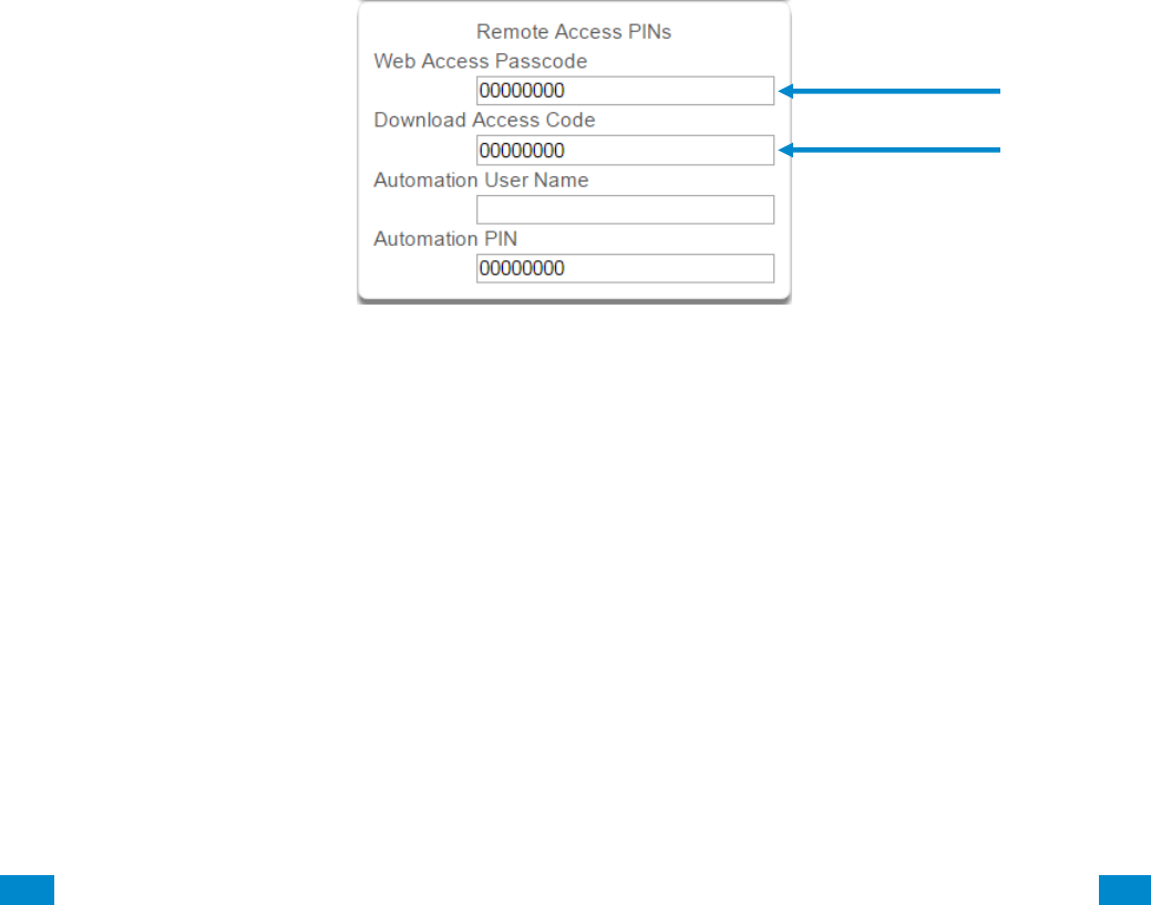
WEB ACCESS PASSCODE AND
DOWNLOAD ACCESS CODE These provide remote access to the UltraSync
Web Server via the UltraSync app and DLX 900 management software.

...C... 44 P/N 466-5261 • REVA • ISS 11NOV16 UltraSync Modular Hub Reference Manual ©2016 United Technologies Corporation .... .I.....
4 The UltraSync App
4.1 Install UltraSync App
UltraSync is an app that allows you to control your hub from an Apple® iPhone/iPad, or
Google Android device. First set up the hub’s Web Server then download this app. Carrier
charges may apply and an Apple iTunes or Google account is required.
On Apple® devices go to the App Store™. On Android devices go to the Google Play™ store.
Search for UltraSync.
Install the app.
Press the icon on your device to launch it.
Press + on the top right to add a new site, or the blue arrow to edit an existing site.
Enter the details of your security system and choose the language you want to use.
The serial number is printed on the back of the panel. Alternatively login to UltraSync Web
Server and go to Settings – Details to view it.
The default Web Access Passcode of 00000000 disables remote access. To change it, login
to the hub’s Web Server and go to Settings - Network.
The default username and PIN code is: installer and 9-7-1-3, and User 1 and 1-2-3-4. You
may also use any other valid user account. Users will only see and have access to menus at
their permission level.
Press the Done button to save the details, then Sites to go back.
4
REFERENCE GUIDE
UltraSync
Modular Hub
...C... 45 P/N 466-5261 • REVA • ISS 11NOV16 UltraSync Modular Hub Reference Manual ©2016 United Technologies Corporation .... .I.....
Press the name of the Site; the app will now connect you to your hub.
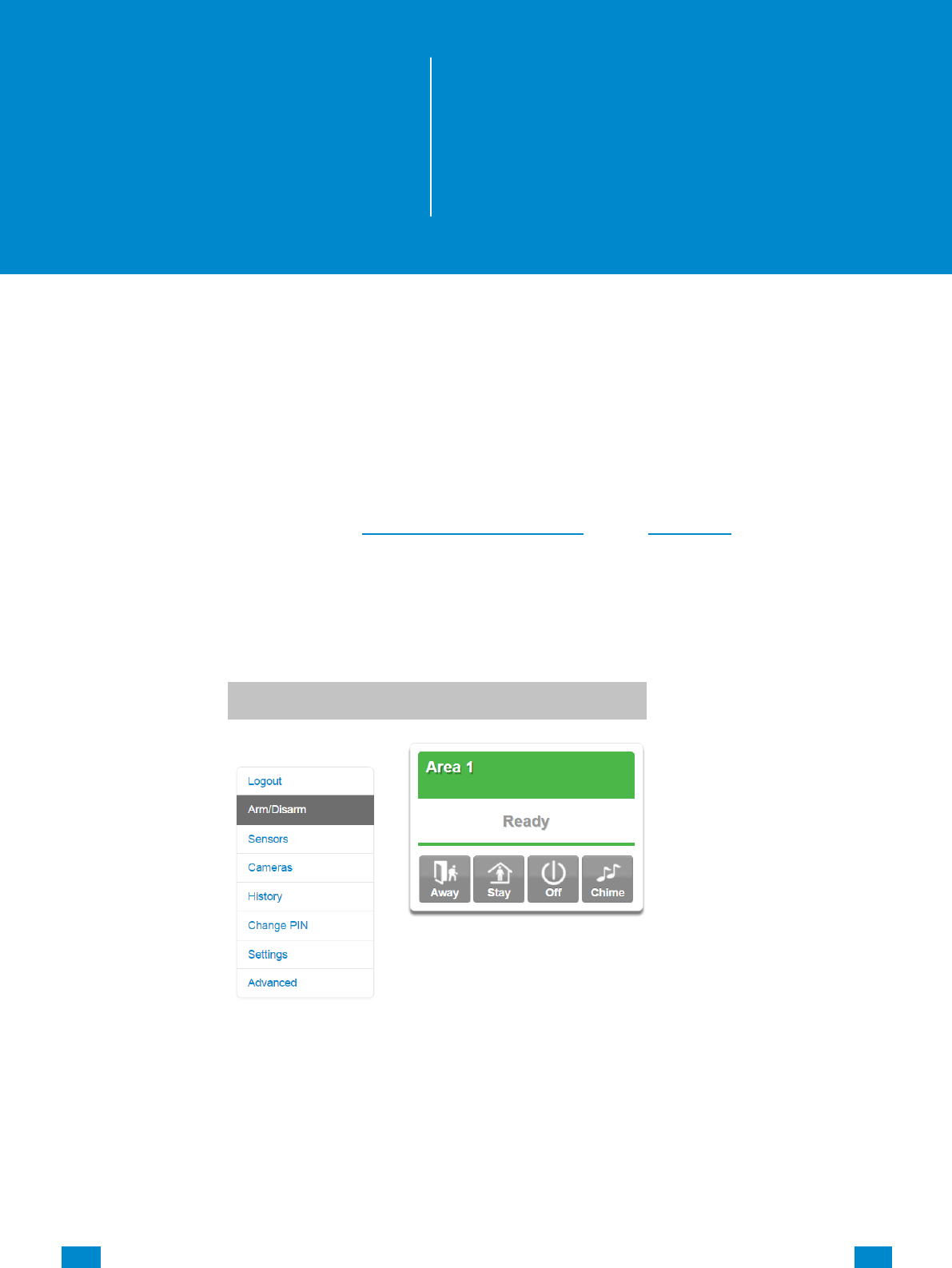
4.1 Using the App
The first screen that will appear once you connect is Arm/Disarm. This will display the status
of your system and allows you to arm or disarm areas by pressing Away, Stay, or Off. From
this screen you can also enable or disable Chime mode.
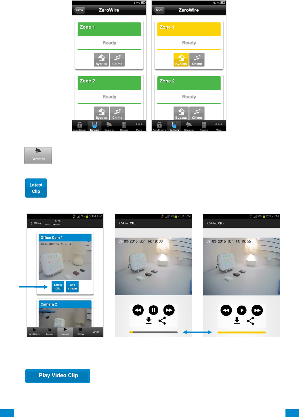
The menu bar is located along the bottom of the screen. Press Sensors to view sensor
status. From the Sensors screen you can press Bypass to ignore a sensor or press it again
to restore it to normal operation. You may also add or remove a sensor from the Chime
feature.
...C... 46 P/N 466-5261 • REVA • ISS 11NOV16 UltraSync Modular Hub Reference Manual ©2016 United Technologies Corporation .... .I.....
Press to view any cameras connected to the system.
This is a live view of the camera.
Press to view the last recorded clip by that camera.
You can also access video clips linked to History events.
Press from the History screen.
clip progress
...C... 47 P/N 466-5261 • REVA • ISS 11NOV16 UltraSync Modular Hub Reference Manual ©2016 United Technologies Corporation .... .I.....
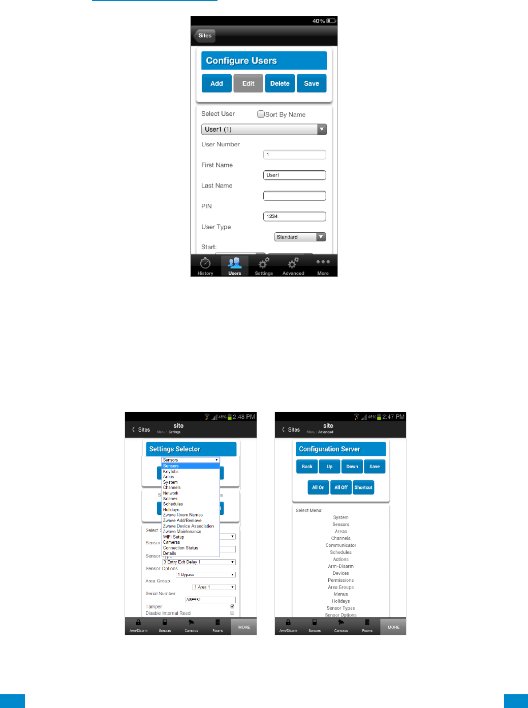
Master users will have access to the full Users menu for creating and managing users.
See Section 7, Users and Permissions for definitions of user levels and permissions.
When you login with the Installer account you will also have access to additional menus for
setting up and programming the system.
Installer menu, Advanced
Installer menu, Settings
...C... 48 P/N 466-5261 • REVA • ISS 11NOV16 UltraSync Modular Hub Reference Manual ©2016 United Technologies Corporation .... .I.....
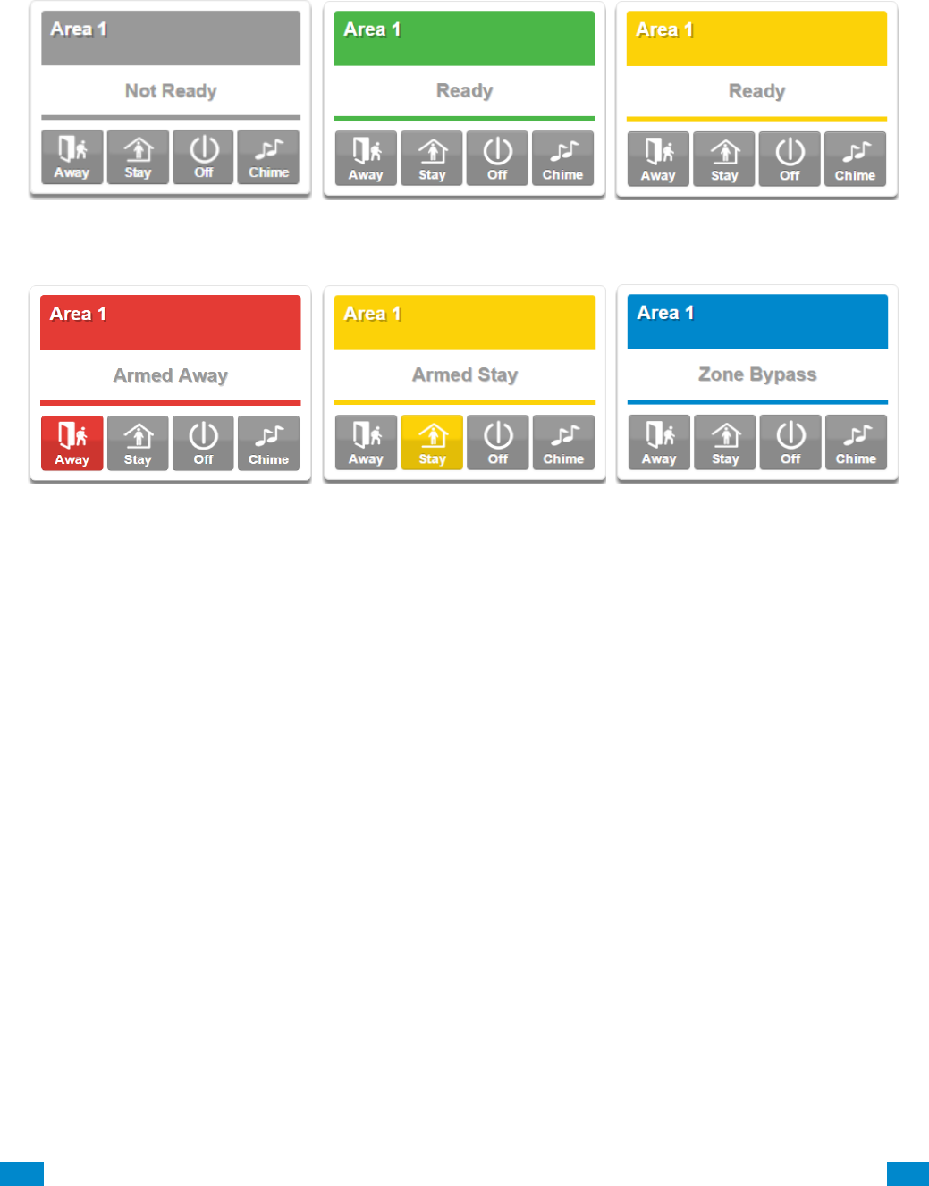
4.2 UltraSync Color Codes
UltraSync’s display tiles are color coded for easy recognition.
Armed, Away
Armed, Stay
Message, Error
Ready
Not Ready
Ready with at least 1 sensor
bypassed

...C... 50 P/N 466-5261 • REVA • ISS 11NOV16 UltraSync Modular Hub Reference Manual ©2016 United Technologies Corporation .... .I.....
5 System Settings
These instructions describe how to program the system. The description and screenshots
depicted below show the procedure utilizing the Web Server. Utilizing the UltraSync app is
virtually identical.
5.1 Learn in Sensors
Connect to the system (either via Web Server Configuration, or the UltraSync app).
Enter your username and password. By default this is installer and 9–7–1–3.
Press Sign In.
You should see a screen similar to one of the below:
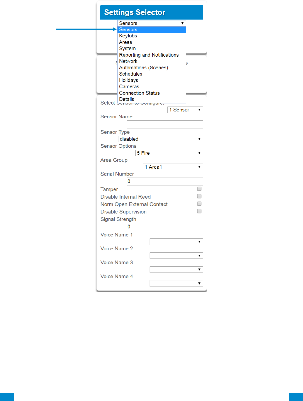
Click on the Settings bar, and then select Sensors from the menu to see the list of
programmable items.
5
REFERENCE GUIDE
UltraSync
Modular Hub
...C... 51 P/N 466-5261 • REVA • ISS 11NOV16 UltraSync Modular Hub Reference Manual ©2016 United Technologies Corporation .... .I.....
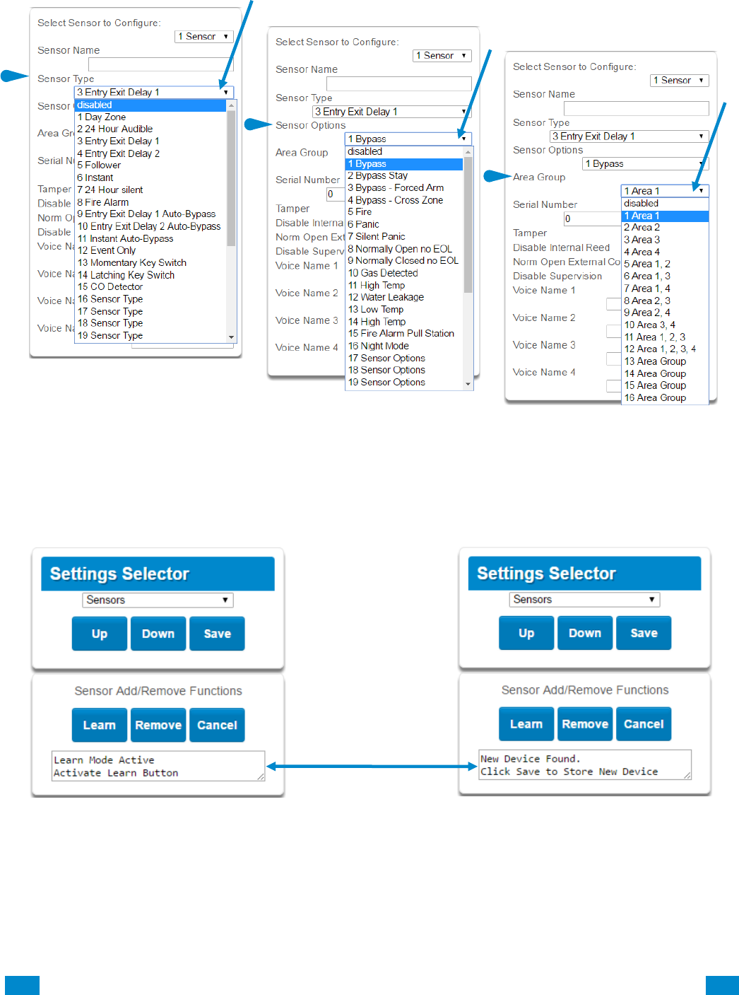
At this point you can type the name of the sensor and define its profile, by determining the
sensor type (Entry, 24 hour, fire, key switch, etc.) and the sensor options (bypass, force arm,
Cross Zone, stay mode, etc.). You can also assign it a specific area. Each of these has a
drop down menu to make selections.
...C... 52 P/N 466-5261 • REVA • ISS 11NOV16 UltraSync Modular Hub Reference Manual ©2016 United Technologies Corporation .... .I.....
When all of your programming definition for the sensor is complete, press Learn if this is a
wireless sensor. A notification box will appear below the learn button. Activate the sensor.
Consult the sensor manual for instructions; generally this is performed by opening the case
and manipulating the tamper activator. This will send a tamper signal. The notification box
will alert you that a new device was found.
Sensor Type
Sensor Options
Sensor Area Group
...C... 53 P/N 466-5261 • REVA • ISS 11NOV16 UltraSync Modular Hub Reference Manual ©2016 United Technologies Corporation .... .I.....
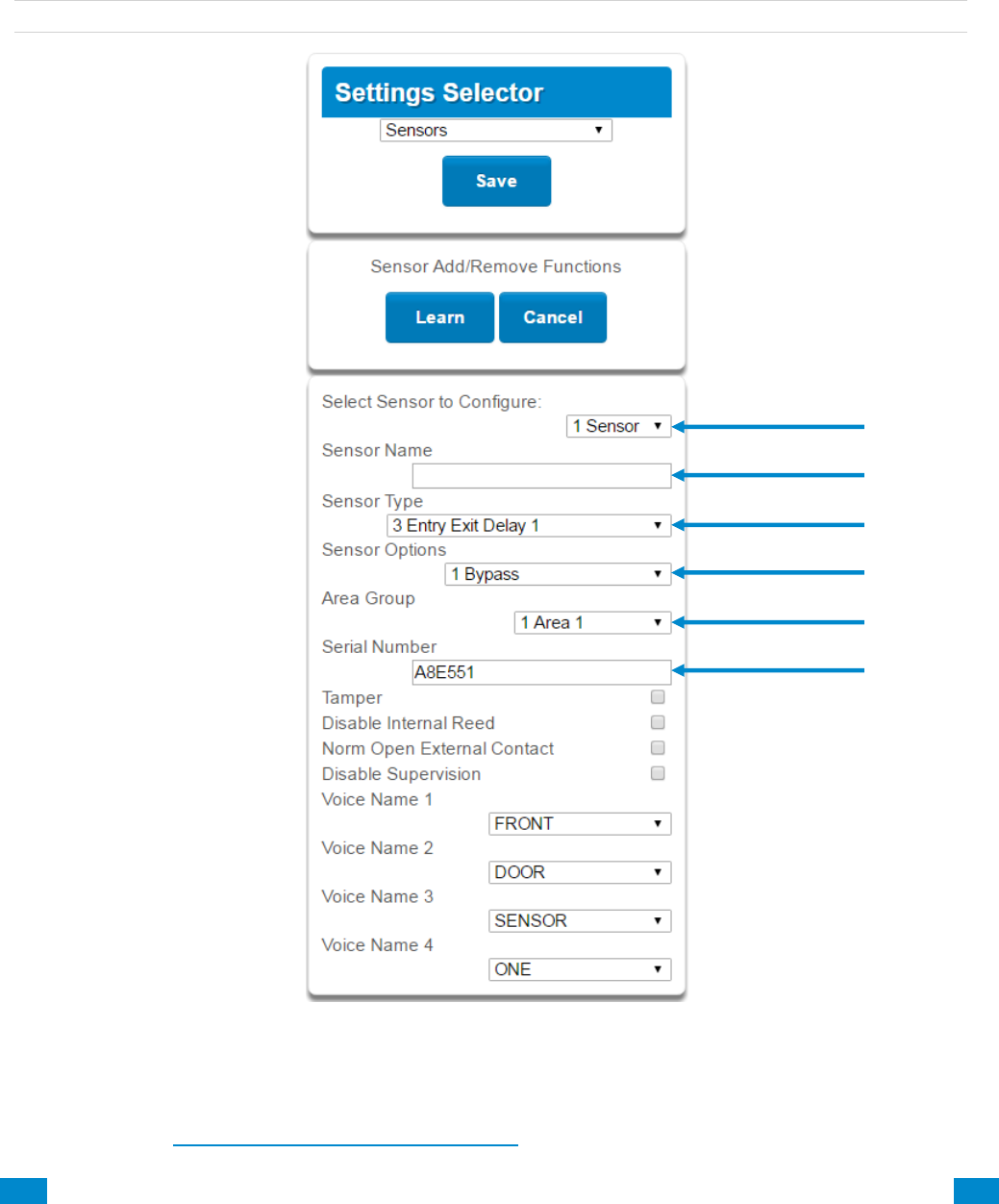
The screen below shows a sensor learned in.
Name: Front Door
Type: Entry Exit Delay 1
Option: Bypass
Area Group: Area 1
Serial Number: A8E551
Note: The sensor’s Serial Number field is populated after learning in the sensor.
Explanations of the sensor configurations appear on the next page.
Also reference Advanced Programming, Sensors, Section 6.
...C... 54 P/N 466-5261 • REVA • ISS 11NOV16 UltraSync Modular Hub Reference Manual ©2016 United Technologies Corporation .... .I.....
S e n s o r C o n f i g u r a t i o n M e n u
Option
Default
Function
Select Sensor to Configure
1 Sensor
Choose among 64 sensors.
Sensor Name
Blank
Custom 32 character name
Sensor Type
3 Entry Exit
Delay 1
Sensor types determine the sensor attributes such as
entry/exit, instant, etc. Additionally sensor types
determine the siren attributes.
Sensor Option
1 Bypass
Sensor options determine the sensor attributes such
as a sensor’s ability to be bypassed, force arm, Cross
Zone, stay mode, etc. Additionally sensor options
determine the sensors reporting attributes.
Area Group
1 Area 1
Assigning a sensor to an area will enable it to report.
Serial Number
Blank
This is the TXID of the wireless sensor, it can be
manual entered or the sensor can be "Learned" into
panel.
Tamper
On
Tamper switch on the wireless sensor is enabled or
disabled.
Disable Internal Reed
Off
The internal reed switch(es) on the wireless device can
be disabled. Applies if the sensor is a device type 10.
Norm Open External Contact
Off
The external input on wireless sensors can be
enabled. Check this box when external contact is
normally open. If the 60-362N-10-319.5 sensor is used
the jumper pin does not have to be used. Applies if the
sensor is a device type 10.
Disable Supervision
(Wireless Sensors)
Off
At default the hub monitors its connections to wireless
sensors, which broadcast supervisory packets to the
panel. Disabling supervision makes the hub
unresponsive to supervisory packets sent from that
sensor. Typically used for mobile sensors such as wrist
panic devices.
Voice Name 1
Blank
This feature uses the internal voice vocabulary to
name the sensor. These names will be announced in
sequence when the sensor is opened while in the
Chime mode.
Voice Name 2
Blank
Voice Name 3
Blank
Voice Name 4
Blank
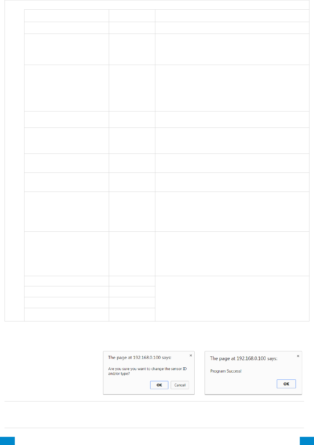
These dialogue boxes appear after any changes to the system are attempted/registered.
Note: After you have finished programming a sensor, be sure to advance the sensor number
in the drop down menu when programming the next sensor. Otherwise you will over-write
the sensor configuration you just programmed.
When you are finished programming the Sensor,
Press the Save button.
A dialogue box appears.
Press the OK button.
A dialogue box appears.
Press the OK button.
...C... 55 P/N 466-5261 • REVA • ISS 11NOV16 UltraSync Modular Hub Reference Manual ©2016 United Technologies Corporation .... .I.....
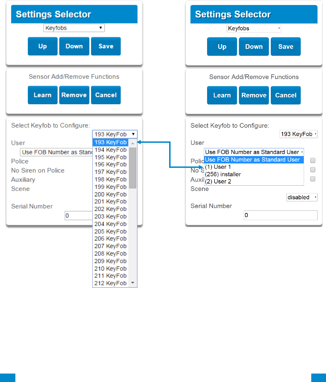
5.2 Learn in a Keyfob
Click on the Settings bar, and then select Keyfobs from the menu to see the list of
programmable items.
With the keyfobs screen selected you can choose the keyfob number to configure and select
the user number to link to the keyfob.
Give the keyfob a number (you are giving the keyfob a sensor number). Select the user and
press Learn. A notification box will appear below the learn button. Activate the keyfob.
Consult the keyfob manual for instructions; this is performed by simultaneously pressing the
lock and unlock buttons. This will send a tamper signal.
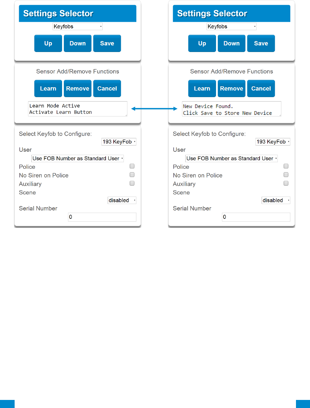
...C... 56 P/N 466-5261 • REVA • ISS 11NOV16 UltraSync Modular Hub Reference Manual ©2016 United Technologies Corporation .... .I.....
The notification box will alert you that a new device (keyfob) was found. The keyfob Serial
Number box will be populated. Explanations of the Keyfob configurations appear on the next
page.
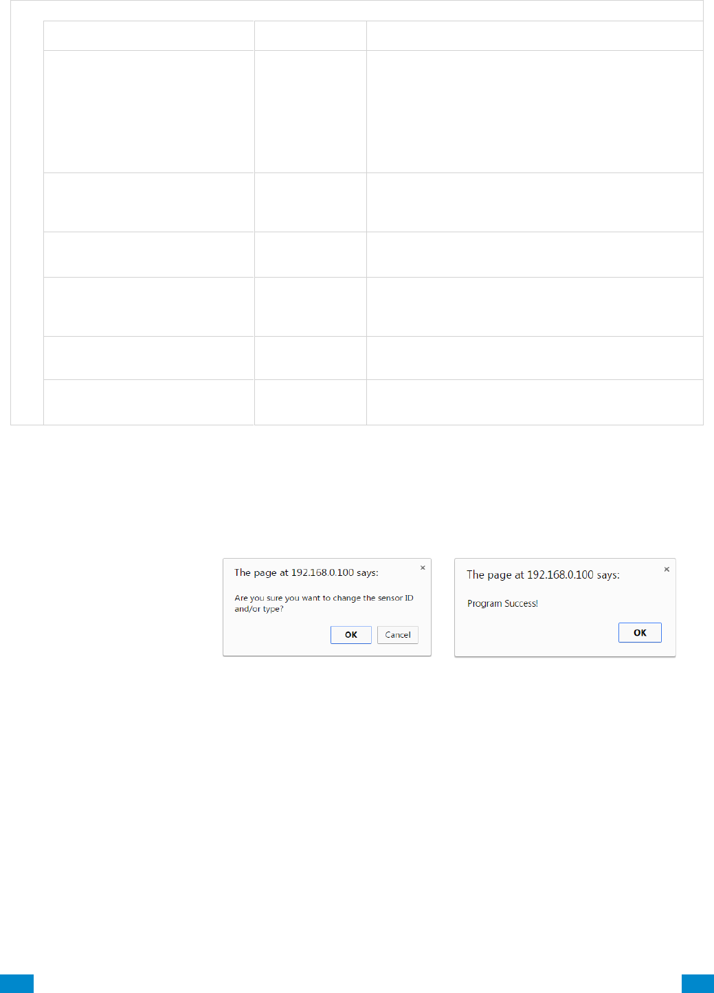
...C... 57 P/N 466-5261 • REVA • ISS 11NOV16 UltraSync Modular Hub Reference Manual ©2016 United Technologies Corporation .... .I.....
Keyfob Configuration Menu
Option
Default
Function
Select Keyfob to Configure
193 Keyfob
This is the starting Sensor number for Keyfobs.
User
Use FOB
Number as
Standard User
If "Use FOB Number as Standard User” is used,
when there is an activation on that Fob the Central
Station report will come in with that sensor number.
If there is a user assigned to the fob that user
number will come in on the Central Station Report. If
no user is assigned it will show as user 999 in the
Central Station Report.
Police
Off
Enabling this will enable the Police / Panic on the
Fob, this will also be audible at the panel (top 2
buttons press at the same time).
No Siren on Police
Off
With this enabled it will make the Police / Panic
silent at the panel.
Auxiliary
Off
Enabling this will enable the Medical / Aux on the
Fob. This will be an audible alarm at the panel.
(bottom 2 buttons pressed at the same time)
Scene
Off
By using the drop down menu one of 16 scenes can
be activated.
Serial Number
Blank
This is the TXID of the Fob, it can be manually
entered or the sensor can be "Learned" into panel.
These dialogue boxes appear after any changes to the system are attempted/registered.
When you are finished programming the Keyfob,
Press the Save button.
A dialogue box appears.
Press the OK button.
A dialogue box appears.
Press the OK button.

...C... 58 P/N 466-5261 • REVA • ISS 11NOV16 UltraSync Modular Hub Reference Manual ©2016 United Technologies Corporation .... .I.....
5.3 Programming Areas
Click on the Settings bar, and then select Areas from the drop down menu to see the list of
programmable items.
With the Areas screen selected you can choose an Area number to configure, give the area
a name, and define attributes for that area.
The system can support a total of 4 areas; each area is configured with its entry and exit
times, area options, area timers, area type and reporting characteristics.
Explanations of the Area configurations appear on the following pages.
Also reference Advanced Programming, Areas, Section 6.3.
Note: When programming Areas 2 and above, a value of 0 for any Area Timer forces the
system to utilize the Area 1 settings for the timer value. Also, a selection of “disabled” for the
Area Channels option forces the system to utilize the Area 1 setting for the Area Channels.

...C... 59 P/N 466-5261 • REVA • ISS 11NOV16 UltraSync Modular Hub Reference Manual ©2016 United Technologies Corporation .... .I.....
A r e a s C o n f i g u r a t i o n M e n u
Option
Default
Function
Select Area to Configure
Area 1
Use the drop down menu to select which of the
4 areas to program.
Area Name
Blank
Each area can be configured with a custom 32
character name. The area name is displayed
wherever an area is referenced on the system.
Area Timers
Entry Time 1 (30-240)
Seconds
30
Provides time to enter into the premises to
deactivate the alarm system.
Exit Time 1 (45 - 255)
Seconds
60
Provides time to exit the premise without
activating the alarm system.
Entry Time 2 (30 - 240)
Seconds
30
If there is a second entry door that requires
more time to deactivate the alarm system.
Exit Timer 2 (45 -255)
Seconds
60
If there is a second exit door that requires more
time to leave.
Stay Enter Timer (30 - 240)
Seconds
30
When the system is armed to "STAY" this will
be the entry time to deactivate the alarm
system.
Area Options
Quick Arm Away (No PIN)
Off
If enabled, the area can be armed in away
mode with a single press. When area is armed
via quick away mode, the closing user number
is the default user of 999.
Quick Disarm - Stay Mode
Off
If enabled, this will allow the stay mode to be
disarmed by pressing the stay key on the
keypad. If the system is in alarm a PIN must be
used.
Manual Panic
On
Enables or Disables the Keypad Panic
Manual Fire
On
Enables or Disables the Keypad Fire
Manual Auxiliary
On
Enables or Disables the Keypad Auxiliary
Force Arm With Bypass
Off
If enabled, the area can be armed even if
sensors are not ready. Any sensors that are not
ready will NOT be automatically be bypassed
and may cause an alarm condition because
they could still be in a not ready state once the
area becomes armed.
This option is overridden if the Force Arm With
Auto-Bypass is enabled.
Individual sensors can be made “force arm-able
without auto-bypass” by leaving this area option
off, then enabling Forced Arm Enable in Sensor
options, and disabling Sensor Inhibit (Bypass)
in the Sensor Type Profile.
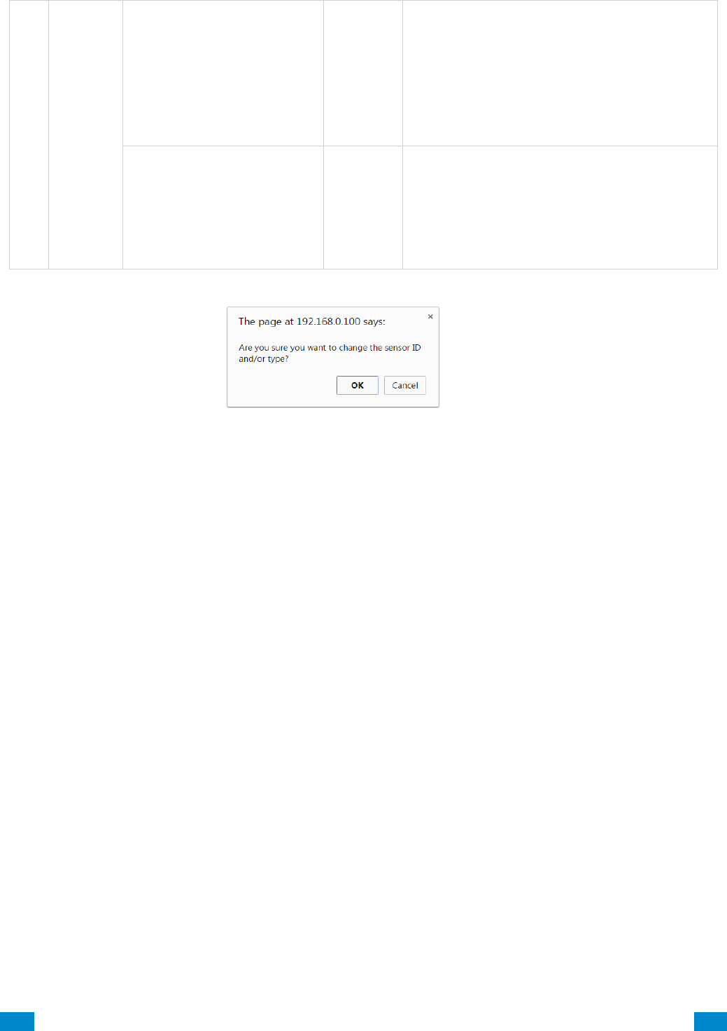
...C... 60 P/N 466-5261 • REVA • ISS 11NOV16 UltraSync Modular Hub Reference Manual ©2016 United Technologies Corporation .... .I.....
Areas Configuration Menu
Area Reporting
Area Account
0
This account number is ONLY used when
sending an email. This should be the same
as the Central Station account number,
however if it is not this will not affect the
Central Station reporting
Area Channels
1
Channel
Group
This determines which channel will be used
to report area events to the Central Station.
The channel must be configured in the
Channel option programming.
When you are finished
programming the Area
settings, remember to
save your changes.
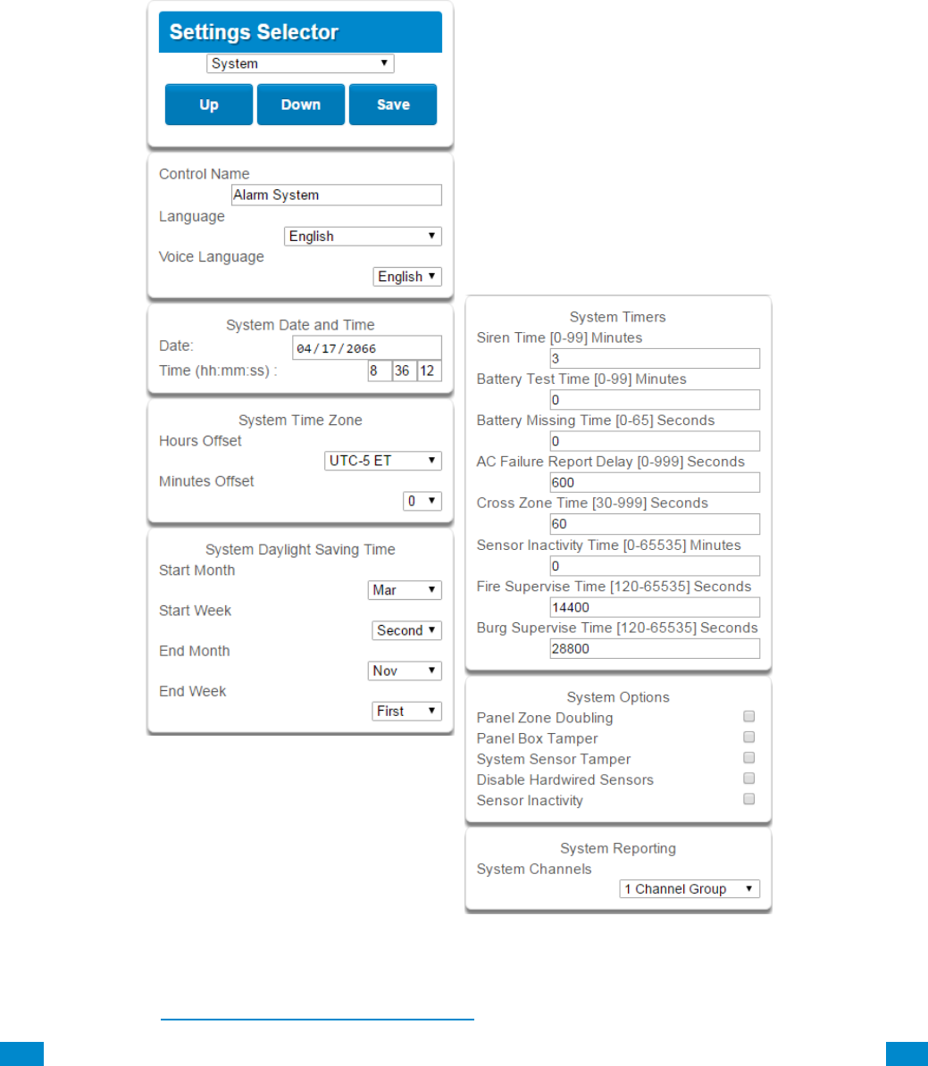
...C... 61 P/N 466-5261 • REVA • ISS 11NOV16 UltraSync Modular Hub Reference Manual ©2016 United Technologies Corporation .... .I.....
5.4 Programming the System
Click on the Settings bar, and then select System from the drop down menu to see the list of
programmable items.
When the System screen is selected you can program several system wide settings,
including the system clock and timers, as well as sensor options and reporting.
When you are finished programming the System settings, remember to save your changes.
Explanations of the System configurations appear on the following pages.
Also reference Advanced Programming, System, Section 6.1.

...C... 62 P/N 466-5261 • REVA • ISS 11NOV16 UltraSync Modular Hub Reference Manual ©2016 United Technologies Corporation .... .I.....
Option
Default
Function
System Configuration Menu
Date
&Time
Date
Once it is connected to UltraSync the Date and time are
automatically synced.
Time (hh:mm:ss)
Once it is connected to UltraSync the Date and time are
automatically synced.
Time
Zone
Hours Offset
UTC 5 ET
EST is UTC-5, CST is UTC-6, MT is UTC-6, PST is UTC-7.
Minutes Offset
0
This is used in other locations throughout the world.
Daylight
Saving Time
Start Month
Mar
Standard
Start Week
Second
Standard
End Month
Nov
Standard
Start Month
First
Standard
System Timers
Siren Time (0-99)
Minutes
4
The siren time sets the time in minutes that the siren output
is active.
Battery Test Time (0-
99) Minutes
2
The battery test time sets the duration in minutes that the
system will perform a dynamic battery test. The system will
perform a dynamic battery test at the disarming of the first
area or at midnight once each 24-hour cycle. Dynamic
battery test is disabled when the test duration is set to 0.
Dynamic battery test can also be run manually from a
keypad.
Battery Missing Time
(0-65) Seconds
0
The battery missing time sets the interval in seconds that
the system will perform a missing battery test. This option
is disabled when the test interval is set to 0.
AC Failure Report
Delay (0-999)
Seconds
300
The AC fail report delay sets the duration in seconds that
the AC power is lost or restored before a communication is
initiated.
AC restore will report when power is maintained for this
same duration.
Cross Zone Time
(30-999) Seconds
300
The Cross Zone time sets the duration in seconds whereby
two or more sensors must trip before an alarm condition
will be registered or the one sensor must trigger twice
within this time period, or a continuous trip longer than 10
seconds. This feature only applies to sensors with the
Cross Zone feature set in sensor options.
Sensor Inactivity Time
(0-65535) Minutes
0
Sensors programmed with Sensor Inactivity in the Sensor
Options must be opened and closed within the time
programmed here (in minutes). If they do not, a Sensor
Inactivity will report. This feature can be enabled in the
System Options menu.
Default Sensor Inactivity option is off and this timer is set to
10080 minutes (7 days).

...C... 63 P/N 466-5261 • REVA • ISS 11NOV16 UltraSync Modular Hub Reference Manual ©2016 United Technologies Corporation .... .I.....
System Configuration Menu
Option
Default
Function
System Timers
Fire Supervise Time
(120-65535)
Seconds
14400
This applies only to wireless sensors programmed as
fire type. Sensors send a reduced packet count
supervisory signal every 60 minutes (check your sensor
manual for most up to date details). If no supervisory
signal is received by the panel within the time specified
here then the sensor will be reported as missing.
When set to 0 the default of 14,400 seconds (4 hours)
will be used. Check your local regulations for the
correct value to use.
Burg Supervise
Time (120-65535)
Seconds
14400
This applies only to wireless sensors programmed as
non-fire type. Sensors send a reduced packet count
supervisory signal every 60 minutes (check your sensor
manual for most up to date details). If no supervisory
signal is received by the panel within the time specified
here then the sensor will be reported as missing.
When set to 0 the default of 43,200 seconds (12 hours)
will be used. Check your local regulations for the
correct value to use.
System Options
Panel Zone
Doubling
Off
If enabled, the eight (8) hardwired sensor inputs will be
doubled to support sixteen (16) sensors. The terminals
for Sensor 1 will represent sensors 1 and 9, and the
terminals for sensor 2 will represent sensor 2 and 10
etc. This option cannot be selected for sensors other
than the eight sensors on the main CPU. This option
cannot be used in conjunction with the DEOL option.
Panel Box Tamper
Off
The system has a built-in normally closed tamper
switch that will sound the siren if the tamper switch is
opened or the wires are cut. This option will enable or
disable this tamper switch.
System Sensor
Tamper
Off
If enabled, the system will monitor all sensors, except
fire sensors, for Dual End of Line (DEOL). A short or
open circuit on a DEOL will activate sensor tamper
alarms. This feature cannot be used if Panel Zone
Doubling is enabled.
Disable Hardwire
Sensors
Off
If enabled, the system will disable all hardwired sensor
inputs on the CPU.
Sensor Inactivity
Off
If enabled, the system will monitor each sensor for
activations. If no activations occur within the sensor
activity time then a failed sensor activity report may be
reported via the selected communication channel and a
failed sensor activity message set in the system event
log. For a sensor to be eligible for activity monitoring, it
must have Sensor Inactivity Test set in Advanced
Programming, Sensor Options.
The Sensor Inactivity Time is set in Advanced
Programming, System – System Timers.
System
Reporting
System Channel
1 Channel
Group
The Channel Group that the system will send system
events to.
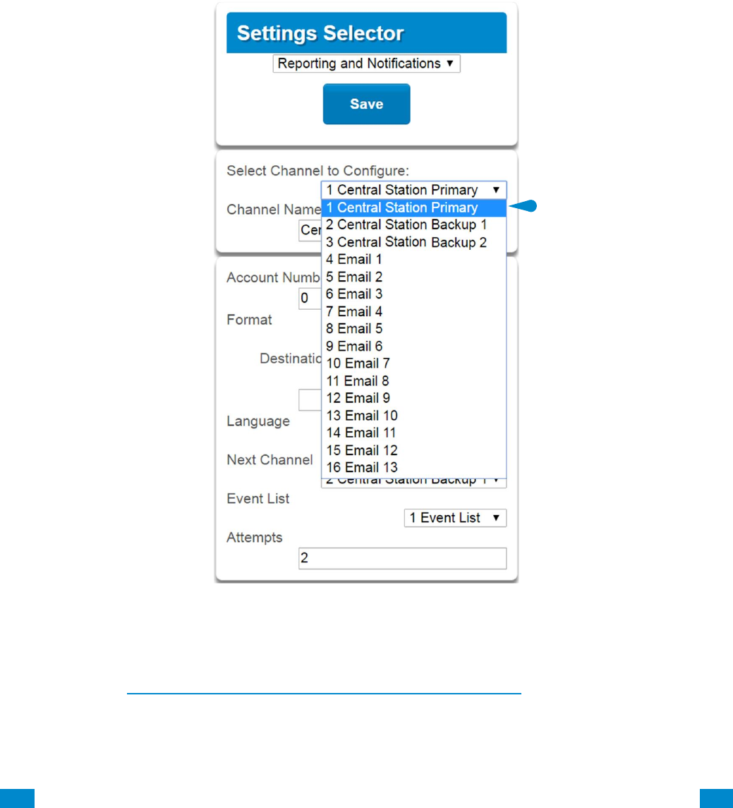
...C... 64 P/N 466-5261 • REVA • ISS 11NOV16 UltraSync Modular Hub Reference Manual ©2016 United Technologies Corporation .... .I.....
5.5 Programming Reporting and Notifications
Click on the Settings bar, and then select Reporting and Notifications from the drop down
menu to see the list of programmable items.
With the Channels screen selected you can program a communication path for events to be
sent from the system to a selected destination.
The system can support a total of 16 channels; each channel is identified by a unique
channel number, which cannot be altered, and remains as the key reference for each
channel.
Choose a channel in the drop down menu and assign it attributes.
Explanations of the Channel Configuration menu appear on the following page.
Also reference Advanced Programming, Reporting and Notifications, Section 6.4.
When you are finished programming the Channel settings, remember to save your
changes.

...C... 65 P/N 466-5261 • REVA • ISS 11NOV16 UltraSync Modular Hub Reference Manual ©2016 United Technologies Corporation .... .I.....
Reporting and Notifications C o n f i g u r a t i o n M e n u
Option
Default
Function
Select Channel to Configure
1 Central Station Primary
Channel Name
Central Station Primary
Custom names of the selected channel
can be created here.
Account Number
Blank
This is the Account Number that will be
reported with the event in email reports.
When UltraSync format is selected, this
field will not be used.
Format
UltraSync
This is the communication format for the
selected channel. Select from:
Use as Backup
CID
SIA 300
SIA 110
UltraSync
Email-Push Notification
Dest Phone, Email or Push
Notification
Blank
The phone number or email address of
the selected destination.
Next Channel
Central Station Backup 1
Central Station Backup 2
Email 1
Email 2
Email 3
Etc.
If the channel selected is unable to
deliver the event to the selected
destination, the system will use this
backup channel if the primary channel
fails. The Next Channel specified here
must be greater than the Channel
Number.
Event List
1 Event List
Select the pre-programmed list of events
that will be sent via this channel. The
specific event in each event list is
programmed in Advanced Programming,
Event Lists.
Attempts
2
Enter the number of times the system
should try to send the events to the
UltraSync server. After the number of
attempts has been exhausted the system
will try the Next Channel if specified.
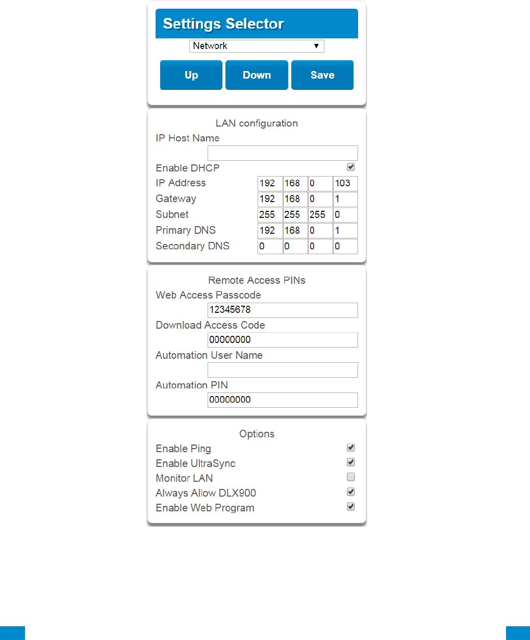
...C... 66 P/N 466-5261 • REVA • ISS 11NOV16 UltraSync Modular Hub Reference Manual ©2016 United Technologies Corporation .... .I.....
5.6 Programming the Network
Click on the Settings bar, and then select Network from the drop down menu to see the list
of programmable items.
Enter your network settings on this page.
Explanations of the Network Configuration Menu appear on the following pages. Remember
to save your changes when you are finished programming the Network settings.

...C... 67 P/N 466-5261 • REVA • ISS 11NOV16 UltraSync Modular Hub Reference Manual ©2016 United Technologies Corporation .... .I.....
Network Configuration Menu
Option
Default
Function
LAN Configuration
IP Host Name
-
The default IP Host Name is xgen. To access the web
server without an IP address, simply type http://xgen into
the web browser. Some browsers to not require http://.
To change the IP Host Name, enter a new IP Host Name
and hit the Save button. The saved change does not
take effect until you log out of the Web server. PC’s
typically cache this address for about 10 minutes. If you
used the default xgen host name and then change it, the
new host name will not be useable for this time frame.
Note: This feature is not supported with Internet
Explorer. This only works on the local LAN and with a
Windows® PC, or an Apple MAC. The PC or MAC must
have Netbios Name Service (NBNS) enabled. It does
not work remotely over the internet. Remote access to
the server is supported via the UltraSync Portal.
Enable DHCP
off
Allows the system to be automatically assigned an IP
address by the network.
IP Address
-
The IP address assigned to the system which enables it
to connect to the local LAN. This will allow you to access
the embedded web server from the system to program
and view the status of the system. It is also used for
alarm reporting.
Gateway
-
If required, the IP address of the router which is needed
when remote IP communications are used.
Subnet
-
The subnet mask for the network. For example,
255.255.255.0 is the network mask for 192.168.1.0/24
Primary DNS
-
The IP address of the Primary Domain Name Server.
The DNS is used to translate host names for time
servers and UltraSync servers.
Secondary DNS
-
The IP address of the Secondary Domain Name Server,
used if the Primary DNS is not available.
Remote Access PINS
WEB Access Passcode
0
The UltraSync app requires the Web Access Code to get
remote access to the panel. The default Web Access
Passcode of 00000000 disables remote access. The
system allows for an 8 digit numeric (only) code. Each
owner should have a unique number.
Download Access Code
0
Enables remote access for DLX 900. This is a variable
length code for the computer user. This code gives the
DLX 900 software complete authority over all menus
including those that are locked. For convenience DLX
900 will also try installer and 9–7–1–3 to allow a
connection if the Download Access Code does not work.
This is why changing the default installer PIN code is
important. The default Download Access Passcode of
00000000 prevents remote access.
Automation User Name
Blank
Used when there is API integration
Automation PIN
Blank
Used when there is API integration
Options
Enable Ping
On
Allows the system to respond to the PING command.

...C... 68 P/N 466-5261 • REVA • ISS 11NOV16 UltraSync Modular Hub Reference Manual ©2016 United Technologies Corporation .... .I.....
Option
Default
Function
Network Configuration Menu
Enable UltraSync
On
This is an automatic feature. It is recommended you
leave this setting on.
Enable this option to allow the system to send email
reports via the UltraSync servers. This is independent
of the Web Access Passcode which when set to
00000000 will prevent the UltraSync app from
connecting.
If any channel is set to Email format reporting, then
the system will override ignore this setting and allow
email reporting via UltraSync cloud servers.
If you wish to prevent connections to the system’s
cloud servers, then uncheck this option and do not use
the UltraSync reporting format.
Also reference the table in Advanced Programming,
Communicator.
Monitor LAN
Off
When the Monitor LAN option is enabled the panel will
monitor the Ethernet port for a valid Ethernet cable. If
the Ethernet cable is disconnected while this option is
enabled and the panel is unable to communicate, it
will log a Fail To Communicate event.
Always Allow DLX 900
On
Enabling this option will allow DLX 900 to connect at
any time if the correct Download Access Code is
provided.
Disabling this option provides greater security by only
allowing DLX 900 to connect when program mode is
active. This allows the system to have DLX 900
access disabled until a user on site with physical
access to the keypad enters program mode with a
valid PIN code.
The system will be in program mode if a user gains
authorized access to the program menu via the
keypad.
Enable Web Programming
On
Enabling this option will cause UltraSync Web Server
and UltraSync app to always display Installer menus
regardless of if the panel is in program mode or not.
Disabling this option will hide the Installer menus on
UltraSync Web Server and UltraSync app unless
program mode is active. This provides greater security
by keeping web programming disabled unless a user
on site with physical access to the keypad enters
program mode with a valid PIN code.
The system will be in program mode if a user gains
authorized access to the program menu via the
keypad.
UltraSync app requires the Web Access Code to
access to the panel.
...C... 69 P/N 466-5261 • REVA • ISS 11NOV16 UltraSync Modular Hub Reference Manual ©2016 United Technologies Corporation .... .I.....
5.7 Programming Automations (Scenes)
Click on the Settings bar, and then select Automations (Scenes) from the drop down menu
to see the list of programmable items.
With the Scenes screen selected you can create scenes on schedules and determine which
event types and device triggers will activate them.
Each scene can trigger up to 16 consecutive scene actions when certain conditions are met.
This can save users time by automatically running multiple actions. A scene can be triggered
manually, through a schedule, or via a system event.
Remember to save your changes when you are finished programming the Scene settings.
Explanations of the Scene Configuration Menu appear on the following pages.
Also reference Advanced Programming, Scenes, Section 6.18.
S c e n e C o n f i g u r a t i o n
S e q u e n c e
During
IF
Does
Then
Perform
Up
To
Action
Action
Activate
Schedule
Area,
Sensor,
Schedule,
User, or
Action
Activate
Event
Type
1
16
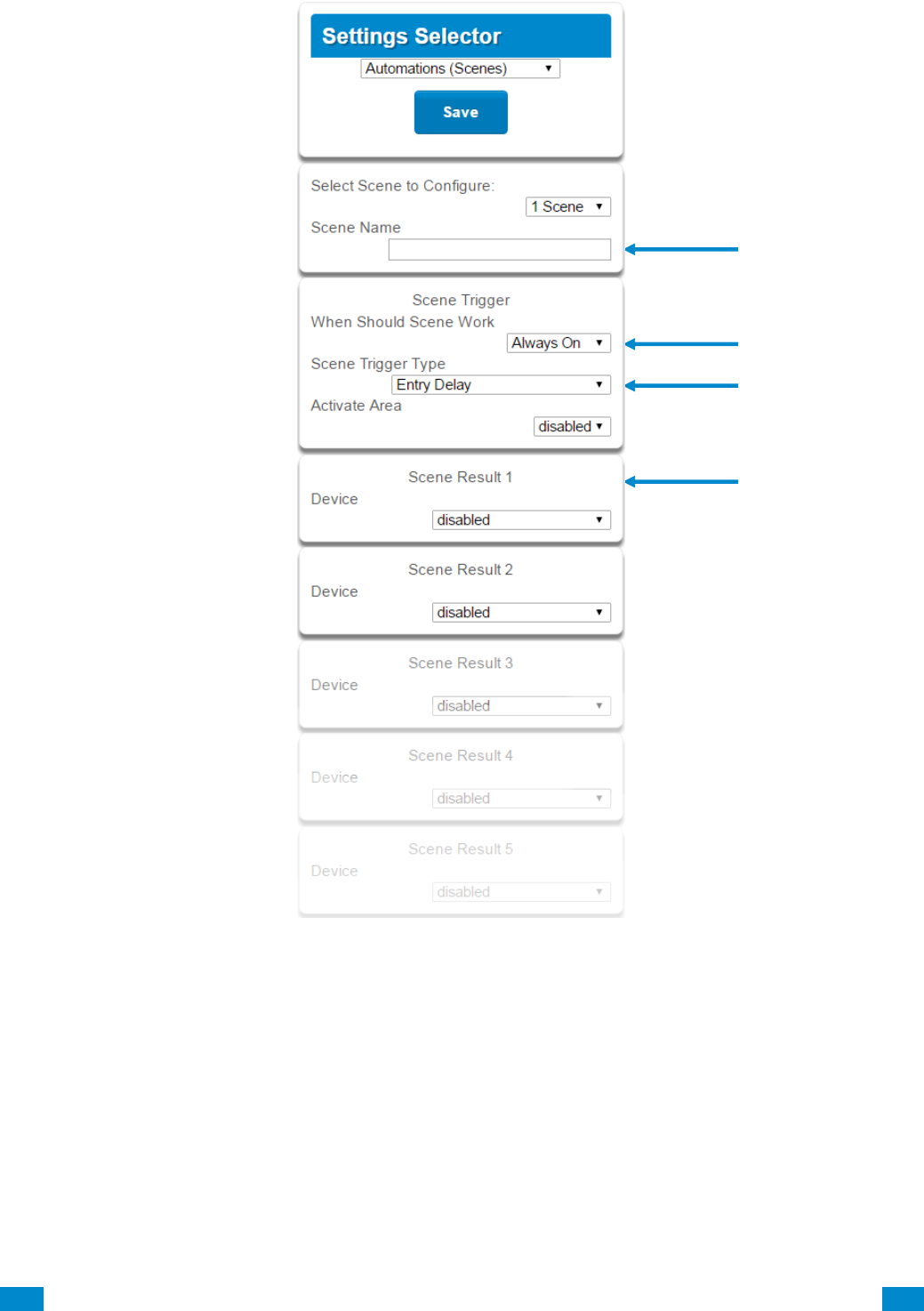
...C... 70 P/N 466-5261 • REVA • ISS 11NOV16 UltraSync Modular Hub Reference Manual ©2016 United Technologies Corporation .... .I.....
Example Scene
1. Enter a scene name.
2. Select the When Should Scene Work drop down menu to restrict when the scene will be
enabled.
3. Select the event that will trigger the automation using the Scene Trigger Type drop
down menu. Choices here dynamically change the “Activate” selections.
4. Select Activate ( - - - - ) to assign what that triggers applies to.
5. Select the Scene Result.
6. Press Save.

...C... 71 P/N 466-5261 • REVA • ISS 11NOV16 UltraSync Modular Hub Reference Manual ©2016 United Technologies Corporation .... .I.....
S c e n e C o n f i g u r a t i o n M e n u
Option
Default
Function
Select Scene to Configure
The system can support a total of 16 Scenes.
Each Scene is identified by a unique number, which
cannot be altered, and remains the key reference for
each Scene.
Scene Name
Each Scene can be configured with a custom 32
character name. The name is displayed wherever a
Scene is referenced on the system.
Scene Trigger
When
Should
Scene
Work
Always On
Select the Schedule that controls when this Scene is
active. If the current date and time is outside of the
selected schedule, then the Scene will not run.
Scene
Trigger
Type
Disable
Select the event that will trigger this Scene. Choices
here dynamically change the “Activate” selections.
You can reference Activate Events list in Advanced
Programming, Scenes.
Activate
( - - - - )
Disabled
Select what triggers the Scene.
Scene Result 1
Device
Disabled
Each scene can perform up to 16 Scene Actions.
These are simplified actions that allow you to control
devices on your system.
There are two types of Results
1. Alarm System Results
2. Z-Wave Device Results.
Alarm System Results
Result Type - The event of the Action Result to
perform. See Advanced Programming, Scenes and the
Scene Action and Scene Action Events Types for
reference.
Result Number - Select the area / scene / camera
number to control:
Z-Wave Device Result
To display Z-Wave Result Types you must first learn in
a Z-Wave device. The Z-Wave device name will then
appear.
Device – select the Z-Wave device you want to control
Z-Wave Type 8 Setting 1 – depends on Z-Wave device.
May include options such as On, Off, Heat, Cool, Auto,
Up, Down, Lock, Unlock.
Scene Result 2
Device
Disabled
Scene Result 3
Device
Disabled
Scene Result 4
Device
Disabled
Scene Result 5
Device
Disabled
Scene Result 6
Device
Disabled
Etc.
Etc.
Etc.
Etc.
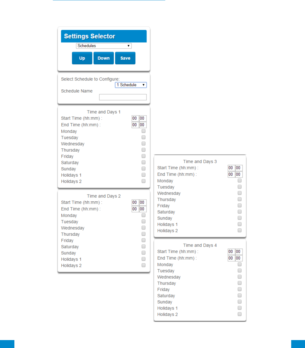
...C... 72 P/N 466-5261 • REVA • ISS 11NOV16 UltraSync Modular Hub Reference Manual ©2016 United Technologies Corporation .... .I.....
5.8 Programming Schedules
Click on the Settings bar, and then select Schedules from the drop down menu to see the
list of programmable items.
With the Schedules screen selected you can create up to 96 schedules, each having four
time and day periods.
Explanations of the Schedules Configuration menus appear on the following pages.
Also reference Advanced Programming, Schedules, Section 6.6.
Remember to save your changes when you are finished programming the Schedules
settings.

...C... 73 P/N 466-5261 • REVA • ISS 11NOV16 UltraSync Modular Hub Reference Manual ©2016 United Technologies Corporation .... .I.....
S c h e d u l e s C o n f i g u r a t i o n M e n u
Option
Default
Function
Select Schedule to Configure
1 Schedule 1
The system can support a
total of 96 schedules. Each
schedule is identified by a
unique schedule number,
which cannot be altered, and
remains as the key reference
for each schedule.
Schedule Name
Schedule 1
Each schedule can be
configured with a custom 32
character name. The area
name is displayed wherever a
schedule is referenced on the
system.
Time and Days 1 -16
Up to 16 Start and Stop times can be created.
Note: The system handles schedules that span midnight automatically
Start Time (hh:mm)
-
Enter in the start time
End Time (hh:mm)
-
Enter in the stop time
Monday
-
Enter in the days of the week
the schedule is to be active
Tuesday
-
Wednesday
-
Thursday
-
Friday
-
Saturday
-
Sunday
-
Holiday 1
-
Enter in the holiday that this
schedule will be following.
Note: When the holiday is
enabled the schedule will not
be active.
Holiday 2
-
Same as Holiday 1
Holiday 3
-
Same as Holiday 1
Holiday 4
-
Same as Holiday 1
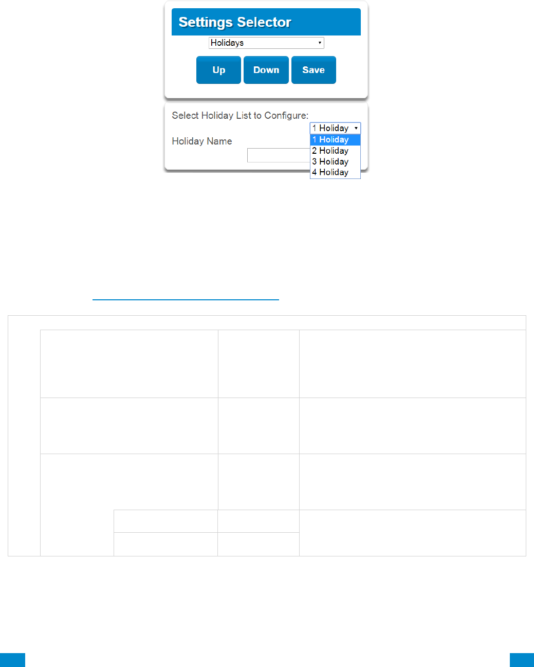
...C... 74 P/N 466-5261 • REVA • ISS 11NOV16 UltraSync Modular Hub Reference Manual ©2016 United Technologies Corporation .... .I.....
5.9 Programming Holidays
Click on the Settings bar, and then select Holidays from the drop down menu to see the list
of programmable items.
With the Holidays screen selected you can create up to four sets of holiday dates for the
system. Set the number, name and date range for each holiday. Holidays are then assigned
to the schedules and used to deactivate the schedule while the holiday is active.
Remember to save your changes when you are finished programming the Holidays settings.
Explanations of the Holiday configurations appear below.
Also reference Advanced Programming, Holidays, Section 6.13.
Holiday Configuration Menu
Option
Default
Function
Select Holiday
List to Configure
n/a
The system supports up to 4 sets of holiday
dates, each set can have up to 16 date ranges.
Holidays are used as part of Schedules to
control access to the system on specified
dates.
Holiday #
1 Holiday
2 Holiday
3 Holiday
4 Holiday
n/a
The system can support a total of 4 Holiday
Sets. Each set is identified by a unique
number, which cannot be altered, and remains
as the key reference for each area.
Holiday Name
n/a
Each holiday can be configured with a custom
32 character name. The name is displayed
wherever a Holiday is referenced on the
system.
Start
-End
Start Date
n/a
Select the date range for the Holiday by
specifying the start and stop date. A total of 16
ranges can be entered for each Holiday.
End Date
n/a
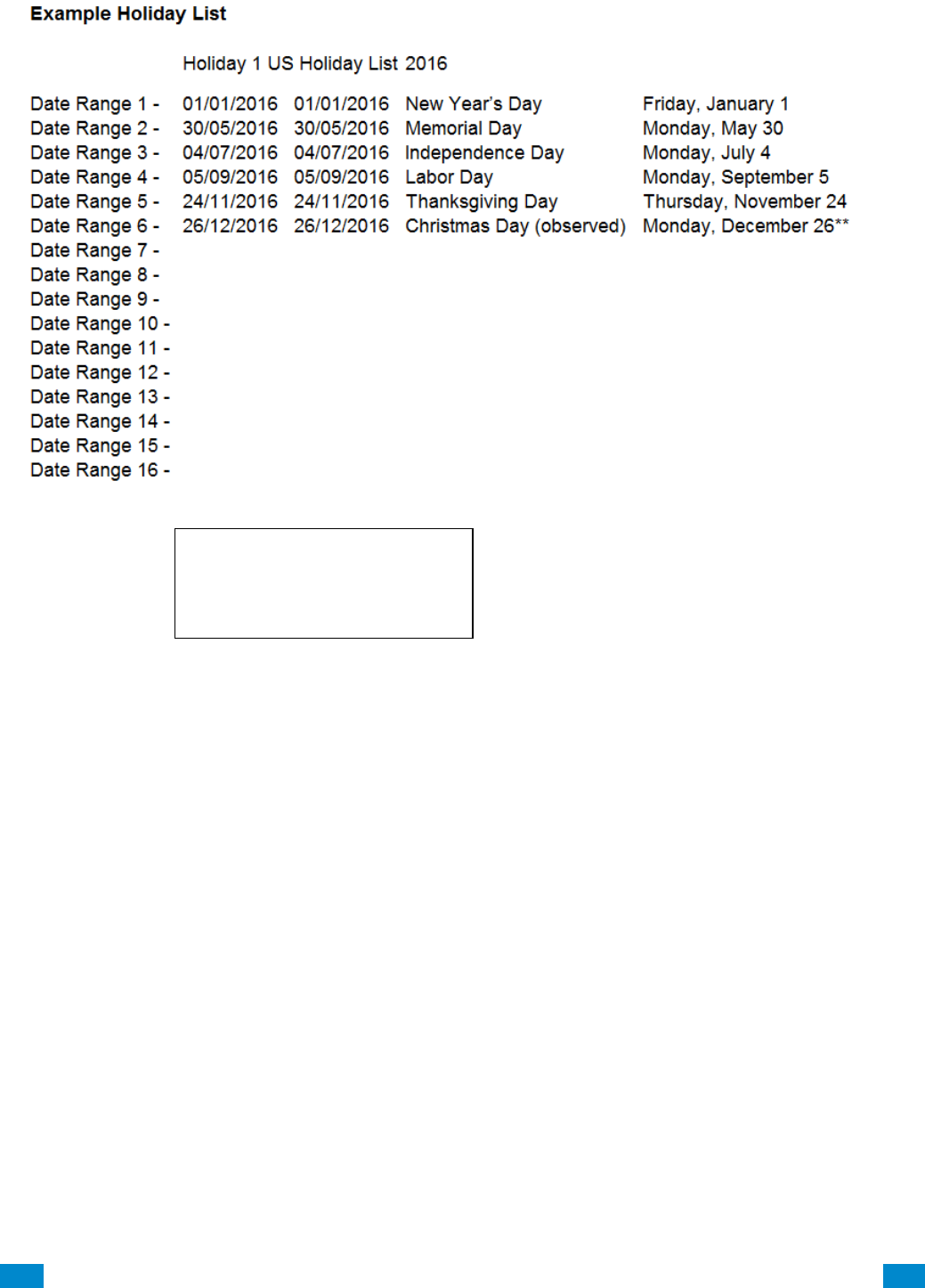
...C... 75 P/N 466-5261 • REVA • ISS 11NOV16 UltraSync Modular Hub Reference Manual ©2016 United Technologies Corporation .... .I.....
Example
An office is not staffed during a public holiday and you want to prevent access to the
building from staff on this date. First program the holiday dates in this section under
“Holiday 1”, then go to Schedules and check “Holidays 1”, then assign that schedule to the
User.
Office Worker
User Permission 1 – All Areas
Permission Schedule 1 – 8am-
8pm M-F, Holidays 1 (checked)
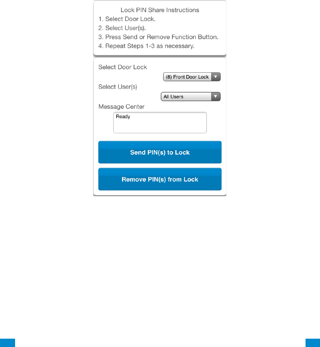
...C... 76 P/N 466-5261 • REVA • ISS 11NOV16 UltraSync Modular Hub Reference Manual ©2016 United Technologies Corporation .... .I.....
5.10 Lock PIN Share
Select Lock PIN Share from the drop down menu.
This function allows you to send user PINs to Z-Wave door locks from the panel.
Select the door lock you want to assign a PIN. Select an existing user (for their PIN) to send
their PIN to the lock. You may also select all users at once.
You may also remove user PINs from a lock, either all at once or by individual user.
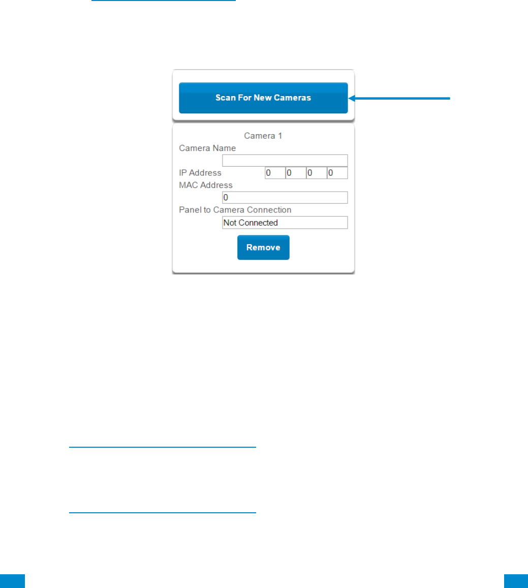
...C... 77 P/N 466-5261 • REVA • ISS 11NOV16 UltraSync Modular Hub Reference Manual ©2016 United Technologies Corporation .... .I.....
5.11 Programming Cameras
Click on the Settings bar, and then select Cameras from the drop down menu to see the list
of programmable items.
The system supports selected IP cameras. Contact your supplier for the correct model(s).
Install camera according to the manual supplied with the camera. Once the camera has
been connected to the same network as the system, proceed with the scanning of the
camera from the system.
Also reference Camera Setup Instructions, Section 9.
Add a Camera Method 1 – Automatic Discovery
Press Scan for New Cameras.
The scan results in an IP address and MAC address listing in the form fields shown.
Viewing Cameras in UltraSync
1. Log in to UltraSync app.
2. Press Cameras.
3. You will now be able to view the live camera feed.
Add a Camera Method 2 – Manual Entry
Reference Advanced Programming, Cameras, Section 6.20.
Removing Cameras
Reference Advanced Programming, Cameras, Section 6.20.
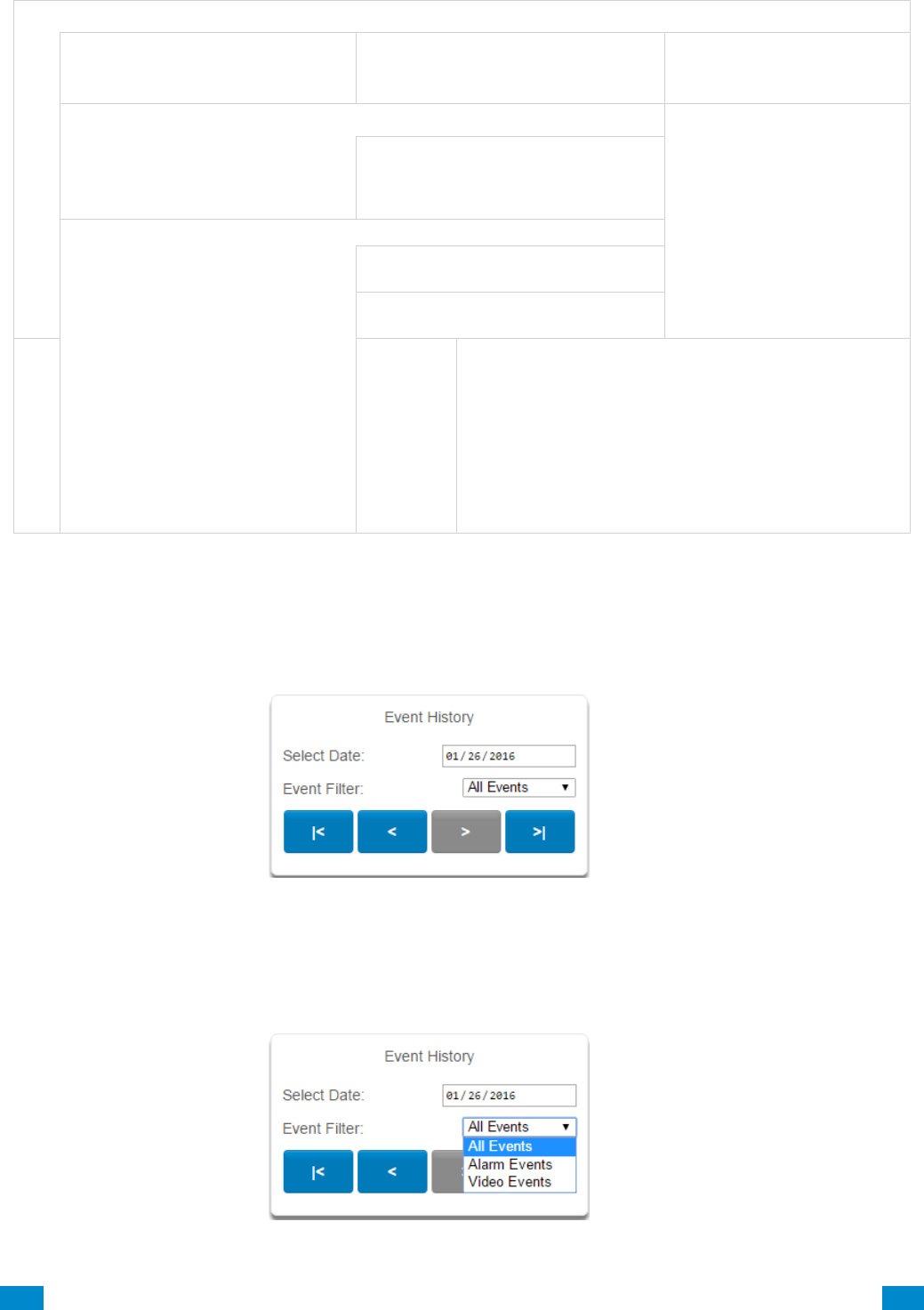
...C... 78 P/N 466-5261 • REVA • ISS 11NOV16 UltraSync Modular Hub Reference Manual ©2016 United Technologies Corporation .... .I.....
C a m e r a M e n u
Option
Default
Function
Scan For New Cameras
-
Finds cameras added to the
same IP network as the
system.
Camera Configuration
Notification
Camera Name drop down (all cameras)
This name can be up to 32
characters. Make sure the name
matches the name you have set up
in the camera app.
Camera Network Configuration
IP Address
IP address assigned to the camera
by the premises network
MAC address
MAC address assigned to the
camera by the premises network
Panel to Camera Connection
-
Displays the last attempt by the panel to communicate
with the camera on the LAN. The panel will try to
communicate when:
1. A clip is triggered
2. Scan for New Cameras function is performed
3. Once per day
Note: This does not indicate a camera to server or
cloud connection; only the LAN.
5.12 Check Event History
The UltraSync Modular Hub allows you to check the history of events that have occurred in
the system. Press History and this menu will appear:
Navigate to events recorded in the system with the arrow buttons. You can select the date
for finding events and use the Event Filter dropdown menus to select among alarm events or
video events. The system stores 1024 alarm events and 1024 video events. The display
shows 10 events at a time.

...C... 79 P/N 466-5261 • REVA • ISS 11NOV16 UltraSync Modular Hub Reference Manual ©2016 United Technologies Corporation .... .I.....
5.13 Check Connection Status
Click on the Settings bar, and then select Connection Status from the drop down menu to
see the system connection status.
Also reference Advanced Programming, System, Section 6.1.
5.14 Check Details
Click on the Settings bar, and then select Details from the drop down menu to view the
system details.
Device Details
Detail
Detail Status
Control Name
Set in System Settings
Device Unique ID (UID)
Unique ID number of the system
Ethernet MAC Address
Ethernet MAC address assigned to the system by the premises network
Control Model
Firmware Version
of the system
Hardware Version
" " "
Bootloader
" " "
Voice Version
" " "
Website Version
" " "
Memory Map Version
" " "
Menu String Version
" " "
Connection Status Menu
Connections
Options
Function
Connection Status
Notification - Diagnostic
LAN Status
Not Linked, Configuring, Connected (system connection status)
Cellular State
1. Idle
2. Getting Details
3. Configuring Modem
4. Modem Connected
5. Configuring PPP
6. Authenticating
7. Configuring Protocol
8. Getting Echo
9. Connected
10. Terminating
11. Idle
UltraSync Status
1. Idle
2. Selecting Server
3. Making Connection
4. Disconnecting
5. Retry Delay
6. Getting Server Hello
7. Connected
UltraSync Path
IP, Cellular
Cellular Radio Details
Cell Service
No Service, Restricted Service, Valid Service
Signal Strength
-113 to -51
Operator ID
Radio Technology
GSM, UMTS
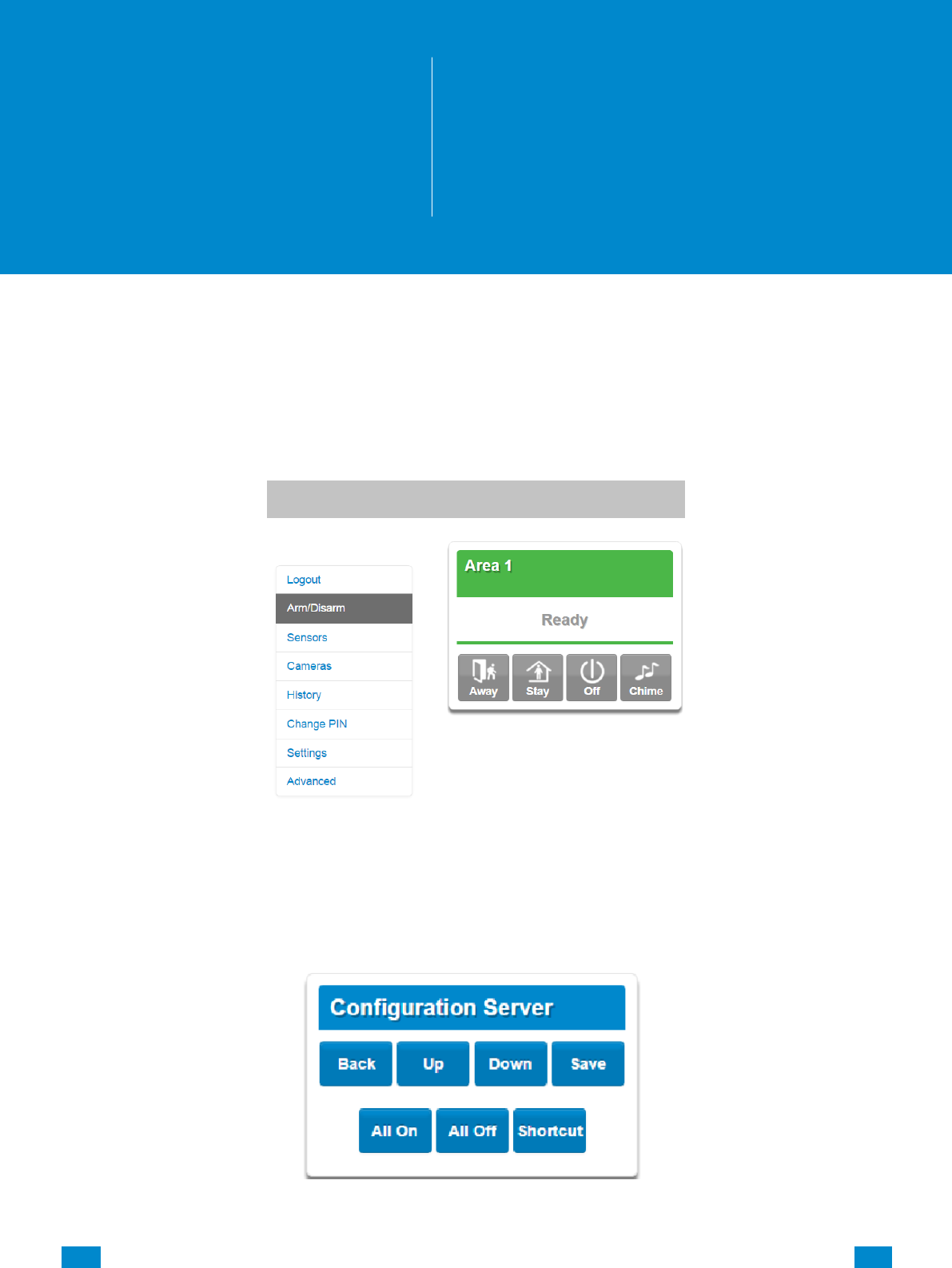
...C... 80 P/N 466-5261 • REVA • ISS 11NOV16 UltraSync Modular Hub Reference Manual ©2016 United Technologies Corporation .... .I.....
6 Advanced Programming Using Web Server
Advanced settings are only accessible via the UltraSync Web Server, UltraSync app, or DLX 900.
Click the Advanced bar to display the advanced menu.
The Configuration Server page main tile contains different buttons than the settings tile.
BACK: Moves you back to the main selection.
UP: Moves you up one option through the programming options.
DOWN: Moves you down one option through the programming options.
6
REFERENCE GUIDE
UltraSync
Modular Hub
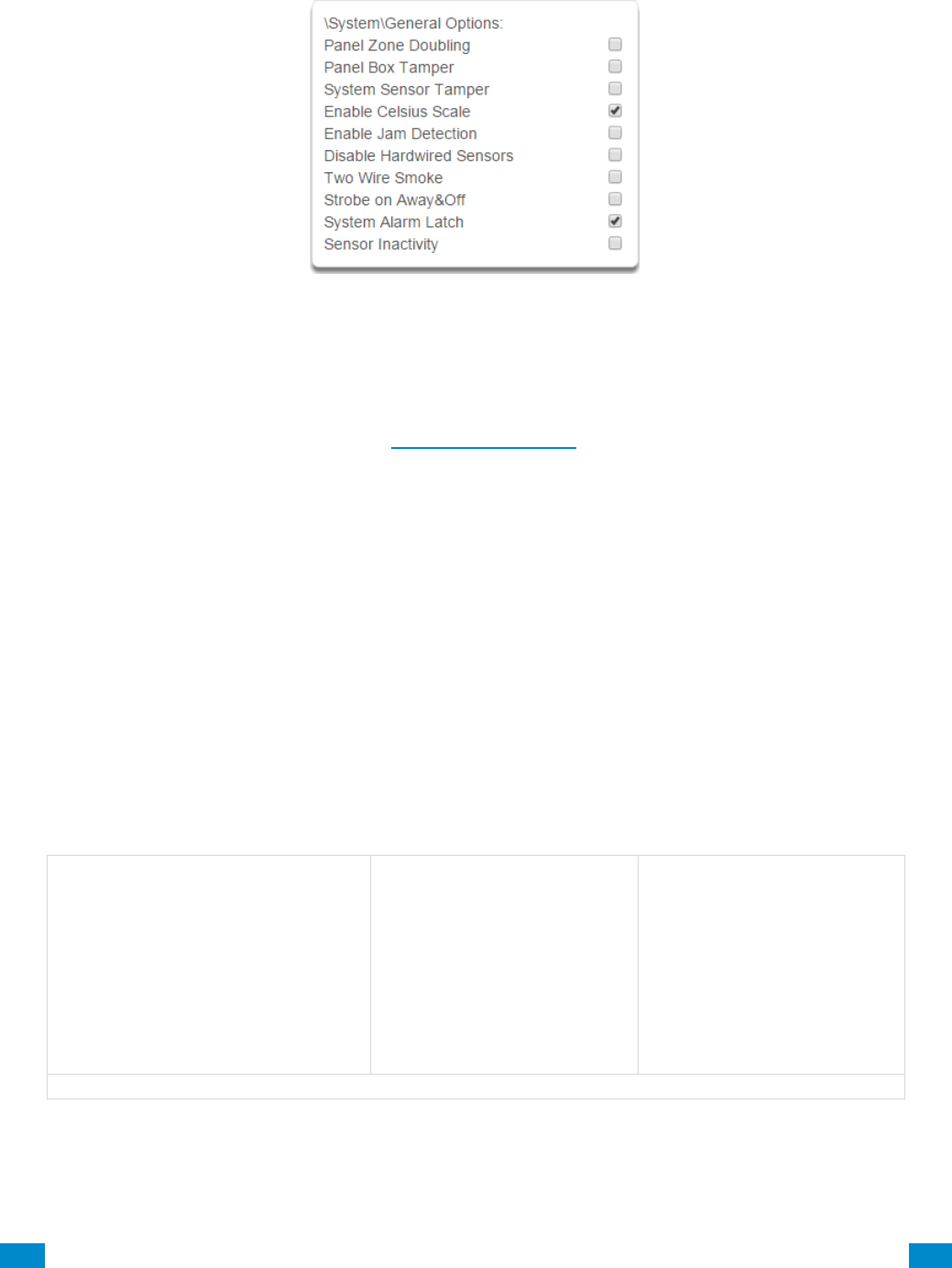
...C... 81 P/N 466-5261 • REVA • ISS 11NOV16 UltraSync Modular Hub Reference Manual ©2016 United Technologies Corporation .... .I.....
ALL ON / ALL OFF: Allows selecting or deselecting all the check boxes in menus like below.
SHORTCUT: Allows quick navigation to the Advanced menu items or defaulting the system.
Quick navigation to Advanced menu:
A prompt will ask you to enter the Menu Shortcut. The format of the entry will be in a
numerical format (X.Y.Z) following the System Menu Tree in Appendix 13. The first digit
designates the top level menu. The second digit designates either the next menu level item
or a specific the
For example, to navigate to the System, General Options, enter a 2.2.1.
To navigate to Sensor # 3, enter 3.3.
Defaulting the system:
A prompt will ask you to enter the Menu Shortcut.The shortcut can be used to either default
the entire system or individual menus. The format is entered in a numerical format (910.xxx).
A value of 910.910 defaults the entire sytem.
To default an individual menu, enter 910.xx where xx designates the menu item to default.
For example, a value of 910.2 will default the System menu items. A value of 910.22 will
default the Cameras menu. See the table below for the numerical value of each menu item.
910.1 Users
910.2 System
910.3 Sensors
910.4 Areas
910.5 Reporting and Notification
910.6 Communicator
910.7 Schedules
910.8 Actions
910.9 Auto Arm-Disarm
910.10 Devices
910.11 Permissions
910.12 Area Groups
910.13 Menus
910.14 Holidays
910.15 Sensor Types
910.16 Sensor Options
910.17 Event Lists
910.18 Channel Groups
910.19 Action Groups
910.20 Scenes
910.21 Speech Tokens
910.22 Cameras
910.23 Network Servers
Table of Menu Default Values
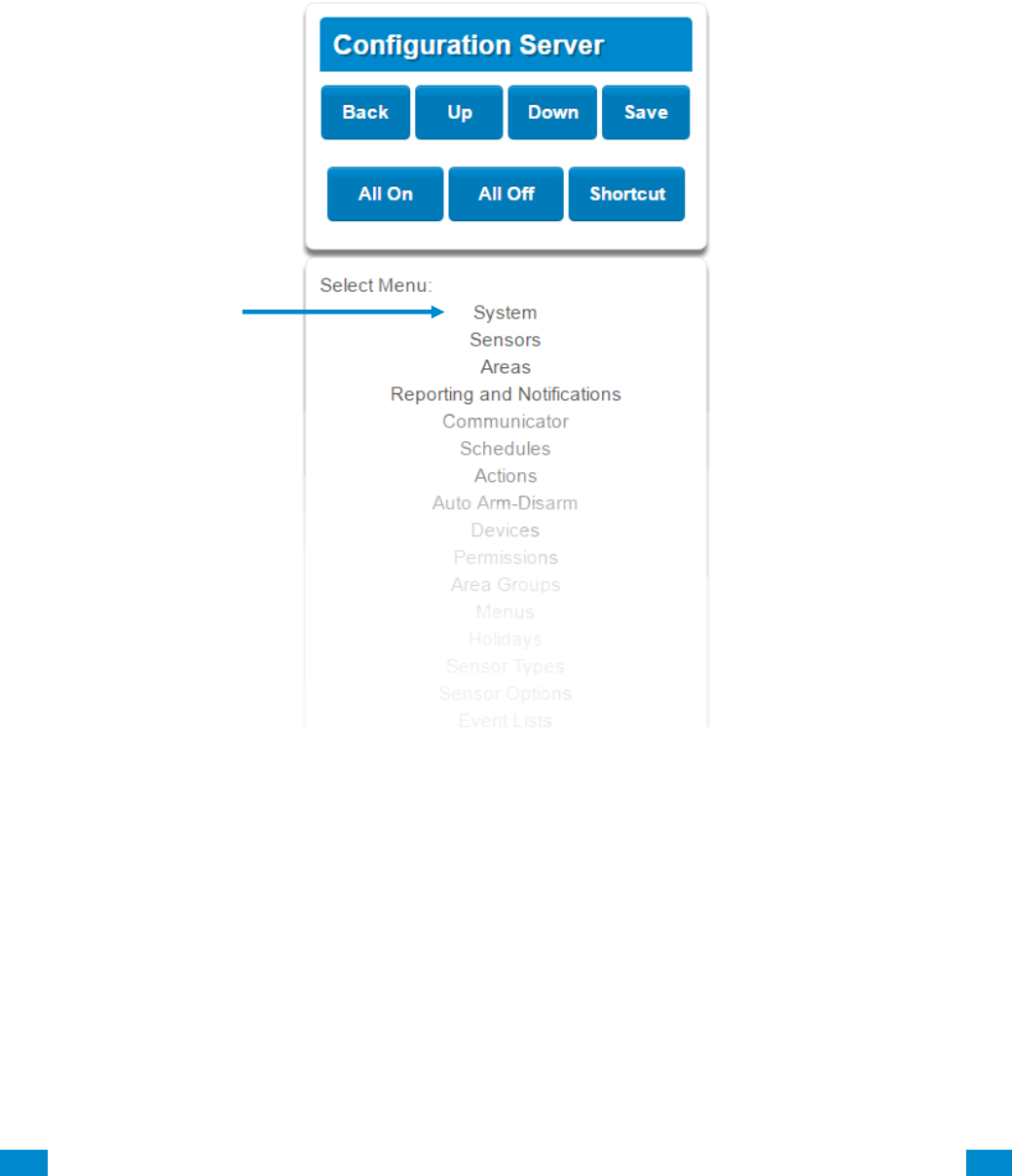
...C... 82 P/N 466-5261 • REVA • ISS 11NOV16 UltraSync Modular Hub Reference Manual ©2016 United Technologies Corporation .... .I.....
6.1 Advanced Programming, System
Click the Advanced bar and select System from the menu to program system options.
System Options is used to configure system wide options, such as time and dates, system
timers and maintenance.
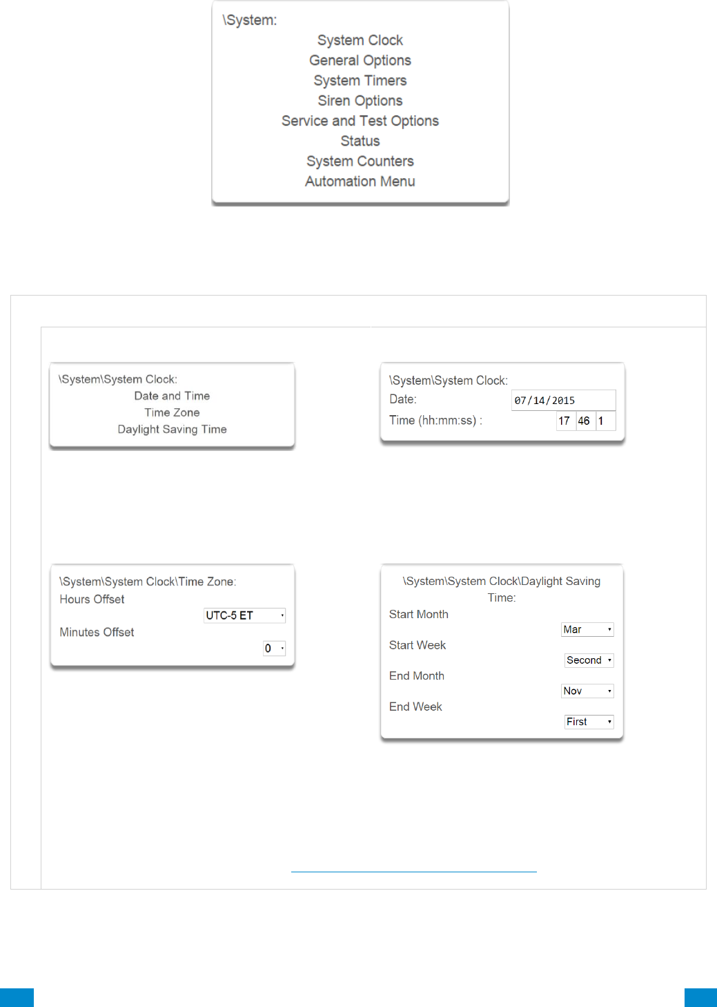
...C... 83 P/N 466-5261 • REVA • ISS 11NOV16 UltraSync Modular Hub Reference Manual ©2016 United Technologies Corporation .... .I.....
S y s t e m S u b m e n u s
S y s t e m C l o c k
1 System Clock
2 Clock Date and Time
The system clock can manage day, time, time sensor, and day light saving time settings to ensure
ongoing accurate time.
3 Time Zone Hours Offset / Minutes Offset
4 Daylight Saving Time
Start Of DLST – Month 1 to 12 of year; Week of
month 1 to 4 and last
End Of DLST– Month 1 to 12 of year; Week of
month 1 to 4 and last
When connected to an IP network the system clock can synchronize its time and date automatically with
an Internet Time Server if configured in Advanced Programming, Communicator.
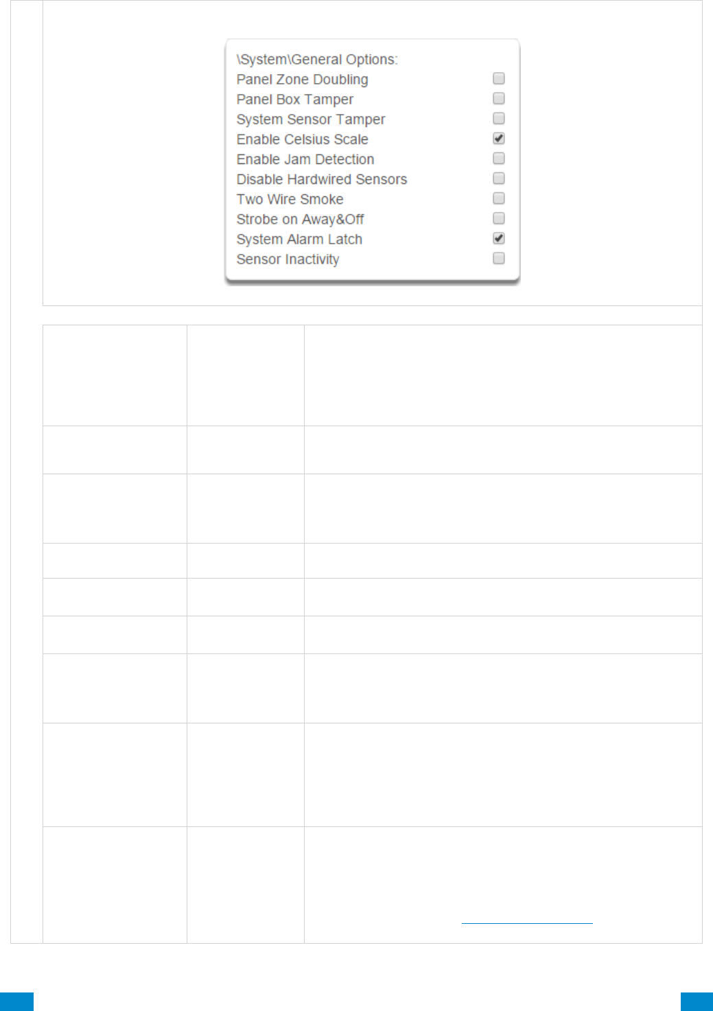
...C... 84 P/N 466-5261 • REVA • ISS 11NOV16 UltraSync Modular Hub Reference Manual ©2016 United Technologies Corporation .... .I.....
S y s t e m G e n e r a l O p t i o n s
1 General Options
Option
Default
Function
Panel Zone Doubling
Off
If enabled, the two (2) hardwired sensor inputs will be doubled
to support four (4) sensors. The terminals for Sensor 1 will
represent sensors 1 and 3, and the terminals for sensor 2 will
represent sensor 2 and 4. This option cannot be selected for
sensors other than the two sensors on the main panel. This
option cannot be used in conjunction with the DEOL option.
Panel Box Tamper
Off
The system has a built-in normally closed tamper switch that
will sound the siren if the tamper switch is opened or the wires
are cut. This option will enable or disable this tamper switch.
System Sensor
Tamper
Off
If enabled, the system will monitor all sensors, except fire
sensors, for Dual End of Line (DEOL). A short or open circuit
on a DEOL will activate sensor tamper alarms. This feature
cannot be used if Panel Zone Doubling is enabled.
Enable Celsius
Scale
Off
Enable Celsius vs. Fahrenheit Scale.
Disable Hardwire
Sensors
Off
If enabled, the system will disable all hardwired sensor inputs
on the CPU.
Two Wire Smoke
If enabled, the system will accept installed two wire smoke
detectors.
Strobe on Away & Off
Off
If enabled, the system strobe will flash when an area is set in
away mode. The strobe outputs must be configured follow the
area alarm event condition. The strobe is not activated on
Disarm or Stay.
System Alarm Latch
On
If enabled, system alarms such as tampers, low battery, A/C
fail and trouble requires a user with “Reset System Alarms”
enabled in their current Permission Options to reset the alarm
condition.
If disabled, system alarms do not latch and can be reset when
a user arms or disarms an area.
Sensor Inactivity
Off
If enabled, the system will monitor each sensor for activations.
If no activations occur within the sensor activity time then a
failed sensor activity report may be reported via the selected
communication channel and a failed sensor activity message
set in the event log. For a sensor to be eligible for activity
monitoring, it must have Sensor Inactivity Test set Advanced
Programming, Sensor Options.

...C... 85 P/N 466-5261 • REVA • ISS 11NOV16 UltraSync Modular Hub Reference Manual ©2016 United Technologies Corporation .... .I.....
S y s t e m T i m e r s
1 System Timers
Option
Default
Function
Siren Time (0-99)
Minutes
4
The siren time sets the time in minutes that the siren output is
active.
Walk Test Time (0-
99) Minutes
15
The walk test time is the duration in minutes before a zone
walk test will automatically end.

...C... 86 P/N 466-5261 • REVA • ISS 11NOV16 UltraSync Modular Hub Reference Manual ©2016 United Technologies Corporation .... .I.....
S y s t e m T i m e r s
Option
Default
Function
Strobe Time (0-99)
Hours
3
The strobe time is the duration in hours that output(s)
programmed to follow the strobe time will activate. The valid time
selection in this segment is 0 to 99 hours, where ‘0’ disables the
Strobe Output. Output 2 on the CPU defaults to follow the Strobe
Time when it is not assigned to an action.
Battery Missing
Time (0-65)
Seconds
0
The battery missing time sets the interval in seconds that the
system will perform a missing battery test. This option is disabled
when the test interval is set to 0.
Battery Test Time
(0-99) Minutes
2
The dynamic battery test time sets the duration in minutes that
the system will perform a dynamic battery test. The system will
perform a dynamic battery test at the disarming of the first area or
at midnight once each 24-hour cycle. Dynamic battery test is
disabled when the test duration is set to 0. Dynamic battery test
can also be run manually from a keypad.
AC Failure Report
Delay (0-999)
Seconds
300
The AC fail report delay sets the duration in seconds that the AC
power is lost or restored before a communication is initiated.
AC restore will report when power is maintained for this same
duration.
Phone Fault Delay
(0-6000) Seconds
0
The phone fault delay sets the duration in minutes before the
phone line fault alarm condition is activated.
Phone Restore
Delay (0-99)
Seconds
0
The phone restore delay sets the duration in seconds that the
phone line fault condition must be restored before the phone fault
alarm is reset.
Cross Zone Time
(30-999)
300
The Cross Zone Time sets the duration in seconds whereby two
or more sensors must trip before an alarm condition will be
registered or the one sensor must trigger twice within this time
period, or a continuous trip longer than 10 seconds. This feature
only applies to sensors with the Cross Zone feature set in sensor
options.
Report Delay (15-
45) Seconds
30
The report delay is the duration in seconds that non-24 hour and
non-fire type sensors will delay before reporting. This provides a
valid user the opportunity to reset an unintended alarm condition
before that event is reported.
Holdup Delay
(0-999) Seconds
0
The holdup delay is the duration in second that a holdup delay
sensor type will wait before it activates. If additional holdup
activations occur during the holdup delay period then the holdup
delay will immediately expire and set the holdup alarm. If a
holdup delay sensor type is de-activated during the holdup delay
period then the holdup alarm will reset and not activate.
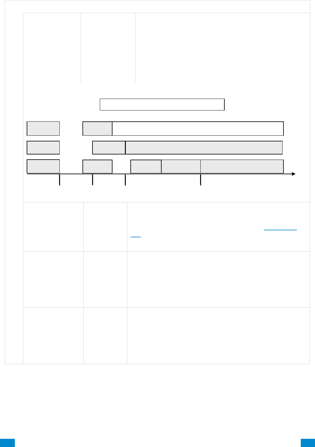
...C... 87 P/N 466-5261 • REVA • ISS 11NOV16 UltraSync Modular Hub Reference Manual ©2016 United Technologies Corporation .... .I.....
S y s t e m T i m e r s
Option
Default
Function
Fire Verify Delay
(0,120-255)
Seconds
120
The fire alarm verification feature is designed to reduce false
alarms reported by smoke detectors.
The system will wait 40 seconds to allow the smoke sensor to
power up and settle. If a second trip occurs after this but
before the end of the Fire Verify Delay time, a fire alarm will be
generated. If no restoral is received after the first trip, a fire
alarm will also be generated.
The valid time selection in this segment is 120 to 255
seconds. The communicator will delay for a specified time
before reporting the fire alarm
Here are some scenarios:
Sensor Inactivity
Time
(0-65535) Minutes
0
Sensors programmed with Sensor Inactivity in the Sensor
Options must be open and closed within the time programmed
here (in minutes). If they do not, a Sensor Inactivity will report.
This feature can be enabled in “System Options”. See Section
5.4.
Default Sensor Inactivity option is off and this timer is set to
10080 minutes (7 days).
Fire Supervise
Time (120-65535)
Seconds
14400
This applies only to wireless sensors programmed as fire type.
Sensors send a reduced packet count supervisory signal every
60 minutes (check your sensor manual for most up to date
details). If no supervisory signal is received by the panel within
the time specified here then the sensor will be reported as
missing.
When set to 0 the default of 14,400 seconds (4 hours) will be
used. Check your local regulations for the correct value to use.
Burg Supervise
Time (120-65535)
Seconds
14400
This applies only to wireless sensors programmed as non-fire
type. Sensors send a reduced packet count supervisory signal
every 60 minutes (check your sensor manual for most up to date
details). If no supervisory signal is received by the panel within
the time specified here then the sensor will be reported as
missing.
When set to 0 the default of 43,200 seconds (12 hours) will be
used. Check your local regulations for the correct value to use.
Reset
Power Up
Fire Alarm Verification Time = 120 seconds
133 s
Waiting for second trip
0 s
1st Trip
Fire alarm reported
Restore
13 s
Reset timer, wait for first trip
Fire alarm
Restore
No restoral
2nd Trip
No alarm
1st Trip
1st Trip
Fire alarm reported
40 s
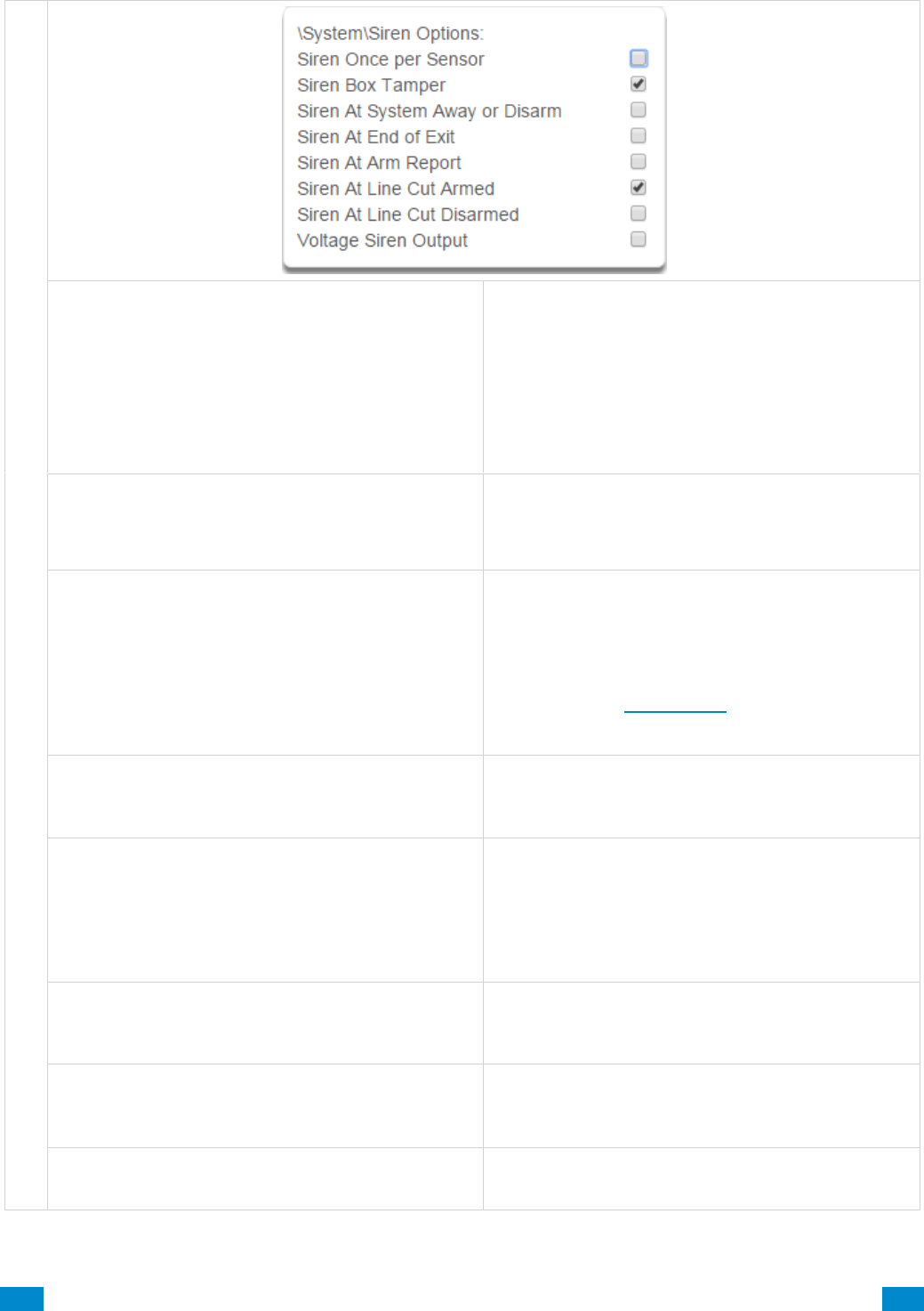
...C... 88 P/N 466-5261 • REVA • ISS 11NOV16 UltraSync Modular Hub Reference Manual ©2016 United Technologies Corporation .... .I.....
S y s t e m S i r e n O p t i o n s
1 Siren Options
Siren Once Per Sensor
If enabled, the system will only activate the siren
once per sensor in a given arm cycle and will not
activate the siren again even if that siren time
expires and that sensor reactivates. Every sensor
will have one siren activation attempt before that
sensor cannot reactivate the siren. If this option is
not enabled, at the expiry of the siren time any
sensor can reactivate the siren an unlimited number
of times.
Siren Box Tamper
If enabled, the system enables the siren box tamper
feature on the CPU Tamp2 terminals. If the siren box
tamper is tripped (e.g. opening the siren cover or
wires cut), then an event will be generated.
Siren At System Away or Disarm
If enabled, the system will activate the siren (Output
1) briefly each time the last area in the system is set
in away mode or when the first area is disarmed by a
keyfob. By default Output 1 is programmed to chirp.
To enable this function by area, leave this option
disabled in this section. Enable the “Siren at System
Away/Disarm” in Area Options of Section 6.3
Advanced Programming, Areas for the area(s) you
require.
Siren At End Of Exit
If enabled, the system will activate the siren (Output
1) briefly each time the system is set in away mode
and the exit delay expires. By default Output 1is
programmed to chirp.
Siren At Arm Report
If enabled, the system will activate the siren (Output
1) briefly each time the system is set in away mode,
with a keyswitch or wireless keyfob. The exit delay
expires and a successful system arm report is
acknowledged from the central station. The siren
will chirp three times. By default Output 1 is
programmed to chirp.
Siren At Line Cut Armed
If enabled, the system will set the siren for the siren
time whenever the phone line is not detected and
any area is armed. The phone line siren can be reset
by the entry of a valid PIN.
Siren At Line Cut Disarmed
If enabled, the system will set the siren for the siren
time whenever the phone line is not detected and all
areas are disarmed. The phone line siren can be
reset by the entry of a valid PIN.
Voltage Siren Output
If enabled, the system will alter the oscillating siren
output suitable for horn speaker to one that is a
steady DC output that is suitable for DC sirens.
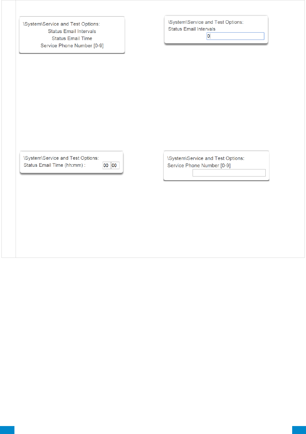
...C... 89 P/N 466-5261 • REVA • ISS 11NOV16 UltraSync Modular Hub Reference Manual ©2016 United Technologies Corporation .... .I.....
S y s t e m S e r v i c e a n d T e s t O p t i o n s
1 Service and Test Options
2 Status Email Intervals
If enabled, the system will report a system status
email via one or more email channels. The number
entered for Status Email Interval is the number of
days between status reports. For example entering a
7 will cause a report to be sent every 7 days.
The interval starts from either the first time you
program an interval in here or when it is powered up.
This is sent via System Event Reporting – Reporting
Channels.
3 Status Email Time
The status email time sets the time of day that the
status email will report. This is set as 24-hour time in
hours and minutes.
4 Service Phone Number
This feature is currently not used. Program the
Company name and telephone number directly into
the UM-1820E keypad by tapping Menu – Settings –
Labels – Installer. When the user taps the SOS –
Installer icons, this contact information will be
displayed on the keypad.
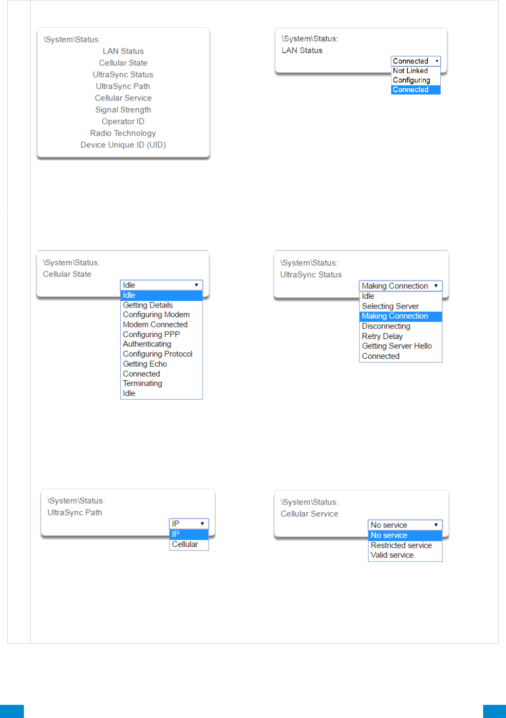
...C... 90 P/N 466-5261 • REVA • ISS 11NOV16 UltraSync Modular Hub Reference Manual ©2016 United Technologies Corporation .... .I.....
S y s t e m S t a t u s
1 Status
This menu provides diagnostic information
on the connection status of the system.
2 LAN Status
Status of the connection to the Local Area
Network.
3 Cellular State
Status of the connection to the cellular radio
network.
4 UltraSync Status
Status of the connection to the cloud servers.
5 UltraSync Path
When connected to the cloud servers whether this is
via LAN (Ethernet/WiFi) or cellular radio.
6 Cellular service
When connected to the cellular radio network this
will display what level of service is provided.
If the optional radio module is installed with a valid
SIM card, and this shows restricted service, please
contact your service provider as your SIM card
may not be provisioned correctly.
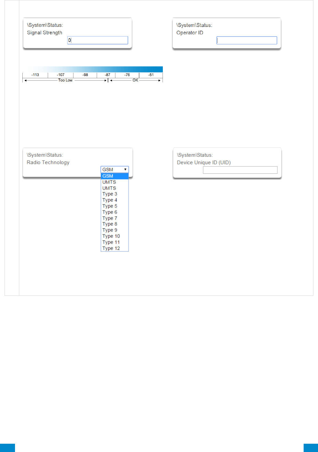
...C... 91 P/N 466-5261 • REVA • ISS 11NOV16 UltraSync Modular Hub Reference Manual ©2016 United Technologies Corporation .... .I.....
S y s t e m S t a t u s
7 Signal Strength
If the optional radio module is installed with a valid
SIM card, this will show the numeric signal level.
If the reported value is -121 to -86 then the signal
level is too low. Install an external antenna to
improve the signal level.
If the reported value is -87 to -51 then the signal
level is OK.
8 Operator ID
If the optional radio module is connected to the
network this will display the ID of the network
operator.
9 Radio Technology
If the optional radio module is connected to the
network this will display the connection technology
such as GSM or UMTS.
10 Device Unique ID (UID)
Unique ID number of the radio module.
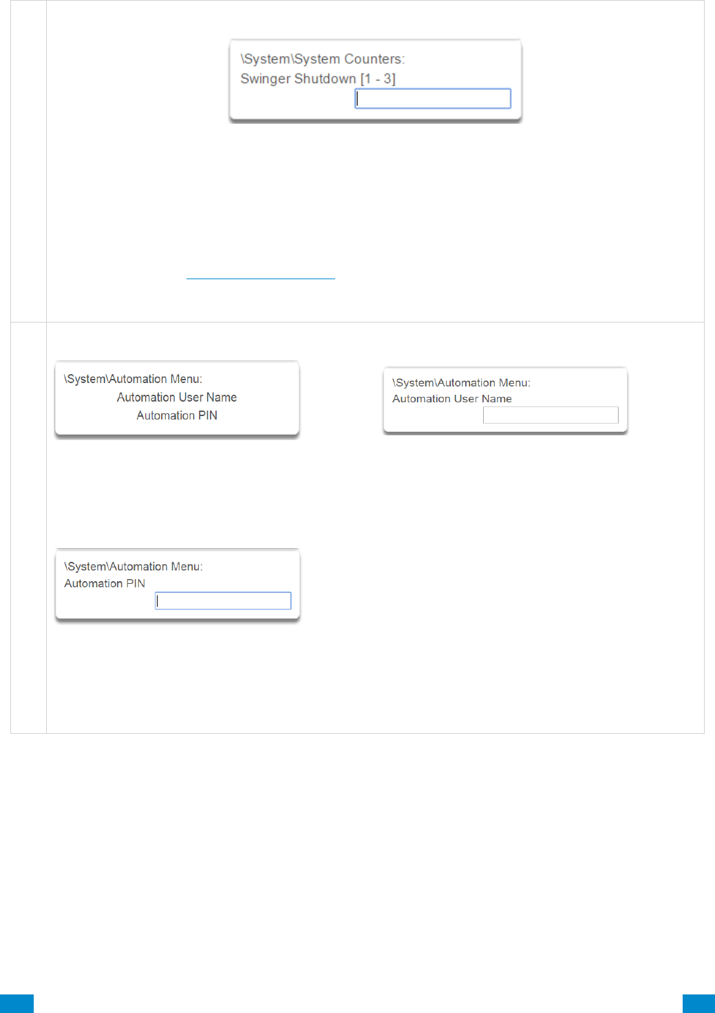
...C... 92 P/N 466-5261 • REVA • ISS 11NOV16 UltraSync Modular Hub Reference Manual ©2016 United Technologies Corporation .... .I.....
S y s t e m C o u n t ers
1 Counters
Swinger Shutdown is a false alarm prevention feature prevents a single sensor from activating more than
a programmed number of times during a single arming period. After a certain number of alarms caused
by the same sensor within the same arming period, the system will then shutdown that sensor for the
remainder of that arming period. The sensor will be reactivated when the system is disarmed or rearmed
to any security mode.
See SIA CP-01-2010 Programmable Features Table for reference.
S y s t e m A u t o m a t i o n M e n u
1 Automation Menu
This menu allows integration of 3rd party
apps and devices.
2 Automation User Name
Used when there is API integration
3 Automation Pin
Used when there is API integration
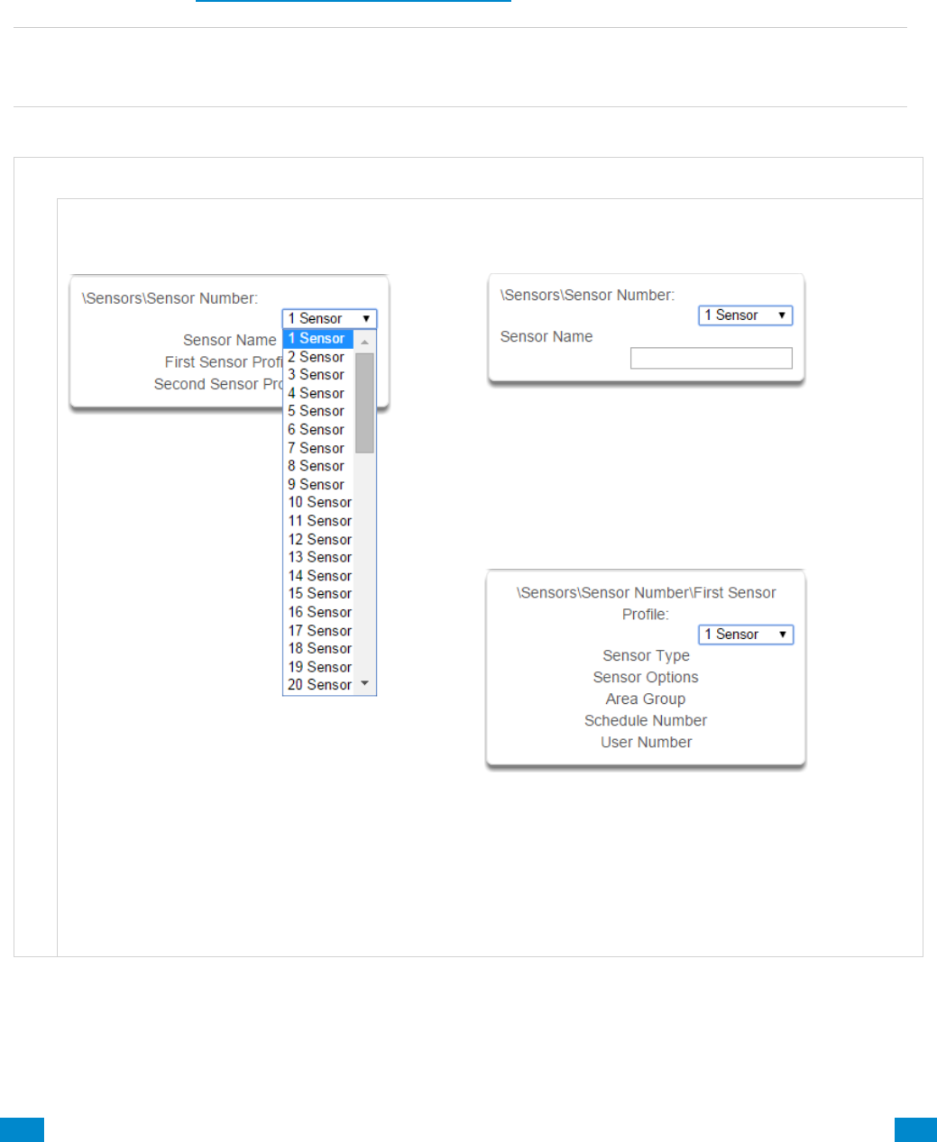
...C... 93 P/N 466-5261 • REVA • ISS 11NOV16 UltraSync Modular Hub Reference Manual ©2016 United Technologies Corporation .... .I.....
6.2 Advanced Programming, Sensors
Click the Advanced bar and select Sensors from the menu to program sensor options.
A sensor (sometimes referred to as a zone or input) on the system is a single physical
hardwired connection or a non-physical wireless connection. Additionally sensors on the
system can be used as logic inputs within actions and / or be configured as one of many
sensor types. See Advanced Programming, Actions.
Note: After you have finished programming a sensor, be sure to advance the sensor number
in the drop down menu when programming the next sensor. Otherwise you will over-write
the sensor configuration you just programmed.
S e n s o r S u b m e n u s
S e n s o r S u b m e n u s
1 Sensor Number
The system can support a total of 64 sensors.
Each sensor is identified by a unique sensor
number, which cannot be altered, and remains as
the key reference for each sensor.
2 Sensor Name
Each sensor can be configured with a custom 32
character name. The sensor name is displayed
wherever a sensor is referenced on the system.
3 First Sensor Profile
Sensor profiles determine the sensor type (Entry, 24
hour, fire, key switch, etc.) and the sensor options
(bypass, force arm, twin trip, stay mode, etc.). Sensor
profiles also determine the area in which the sensor
resides in. Additionally, each profile has a schedule
that the system uses to determine which of the two
sensor profiles to use and when to use them.
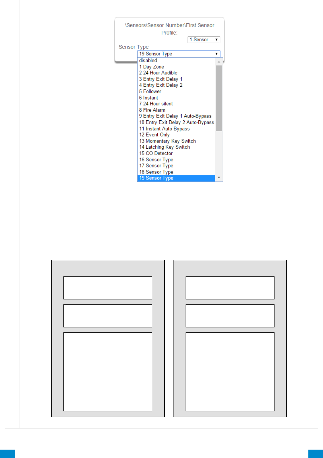
...C... 94 P/N 466-5261 • REVA • ISS 11NOV16 UltraSync Modular Hub Reference Manual ©2016 United Technologies Corporation .... .I.....
S e n s o r S u b m e n u s
4 Sensor Type
One of 32 configurable sensor types may be allocated to any sensor’s sensor type. Each sensor type can
behave independently between an arm and disarmed state. Sensor types determine the sensor attributes,
siren attributes, and sensor attribute options.
Here is an example of a preset sensor type:
Sensor Type – 1 – Day Sensor
Sensor Type Armed
Sensor Attribute - Instant
Siren Attribute - Yelping
Sensor Attribute Options:
Keypad Sounder YES
Report Delay NO
No Keypad Display NO
Momentary Switch NO
Sensor Inhibit (Bypass) NO
Sensor Type Disarmed
Sensor Attribute - Local
Siren Attribute - Silent
Sensor Attribute Options:
Keypad Sounder YES
Report Delay NO
No Keypad Display NO
Momentary Switch NO
Sensor Inhibit (Bypass) NO
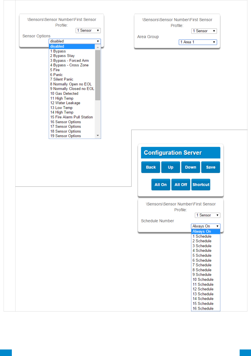
...C... 95 P/N 466-5261 • REVA • ISS 11NOV16 UltraSync Modular Hub Reference Manual ©2016 United Technologies Corporation .... .I.....
S e n s o r S u b m e n u s
5 Sensor Options
One of 32 configurable sensor options may be
allocated to any sensor. Sensor options determine
the sensor attributes such as a sensor’s ability to
be bypassed, force arm, cross zone, stay mode,
etc. Additionally sensor options determine the
sensor’s reporting attributes.
One of 16 configurable schedules can be allocated
to any sensor’s schedule number. Sensor profile
schedules determine when to allocate a sensor
profile to a sensor. The first sensor profile has the
highest priority and the second sensor profile has
the lowest priority.
The panel will check if the current time and day fall
within the schedule of the first sensor profile or if
the schedule is disabled (thus always active). If the
schedule is active then that profile is
applied to that sensor.
If the first sensor profile’s schedule is not active
then it will check the second sensor profile. If the
schedule is active then that profile is
applied to that sensor.
6 Area Group (1-16)
One of 16 configurable area groups can be
allocated to any sensor’s area group. Area groups
are a list of system areas. When an area group is
allocated to a sensor, that sensor will then belong
to all the areas in the area group. If a sensor is
assigned to multiple areas it will not arm until the
last area is armed. It will also be disarmed when
the first area is disarmed.
Ensure the correct Area Group is assigned to a
sensor. If an area Group with no areas is used,
then the sensor will never report.
7 Schedule Number
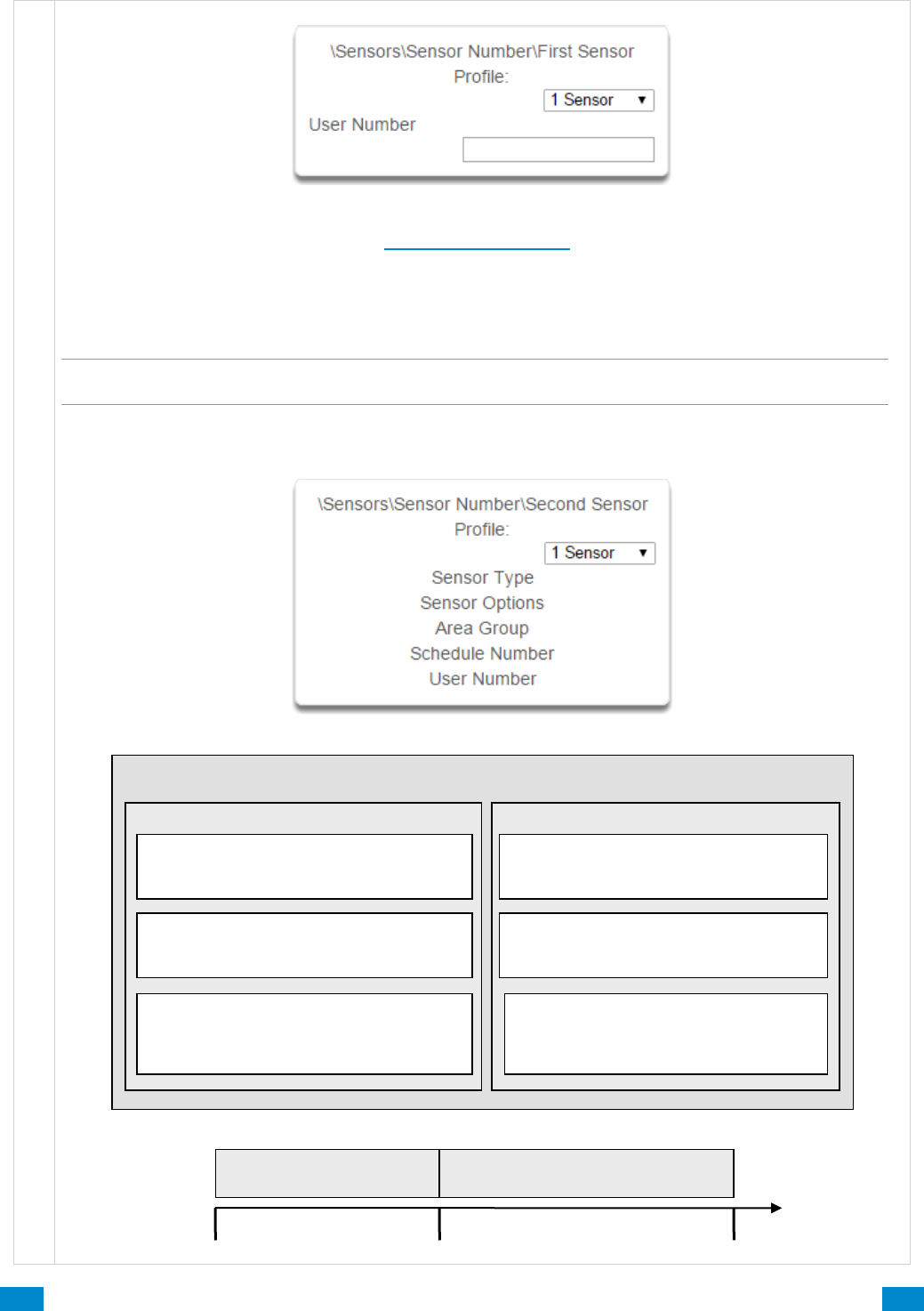
...C... 96 P/N 466-5261 • REVA • ISS 11NOV16 UltraSync Modular Hub Reference Manual ©2016 United Technologies Corporation .... .I.....
S e n s o r S u b m e n u s
8 User Number
The sensor user number feature is used whenever the sensor type is set to “keyswitch”. Instructions for
users’ configurations are in Section 7 – Users and Permissions. One of 256 configurable users can be
allocated to any sensor’s user number. The system’s sensor profile user number is a powerful feature
that is used to apply the selected user’s attributes to a keyswitch operation. When the keyswitch sensor
is activated, the system will check the user permissions and permission schedules to determine which
areas are accessible. Additionally, area open and close reports will also report the user number selected
in this option.
Note: If the user number is programmed to 0, the system will use a default User number of 999 and will
operate on all areas in the sensors area group.
9 Second Sensor Profile (Refer to First Sensor Profile)
Example Diagram
Sensor Programming
6pm
8am
8am
Sensor 12 – Living Room Motion Sensor
First Sensor Profile
Sensor Type – Event Only
Event Only
Always On
Sensor Options – Bypass Forced Arm
Schedule 1 – Office Hours
Mon-Fri, 8am-6pm, Holidays 1
Second Sensor Profile
Sensor Options – Bypass Forced Arm
Schedule 2 –
Always On All Days, 24/7
Sensor Type – Always On
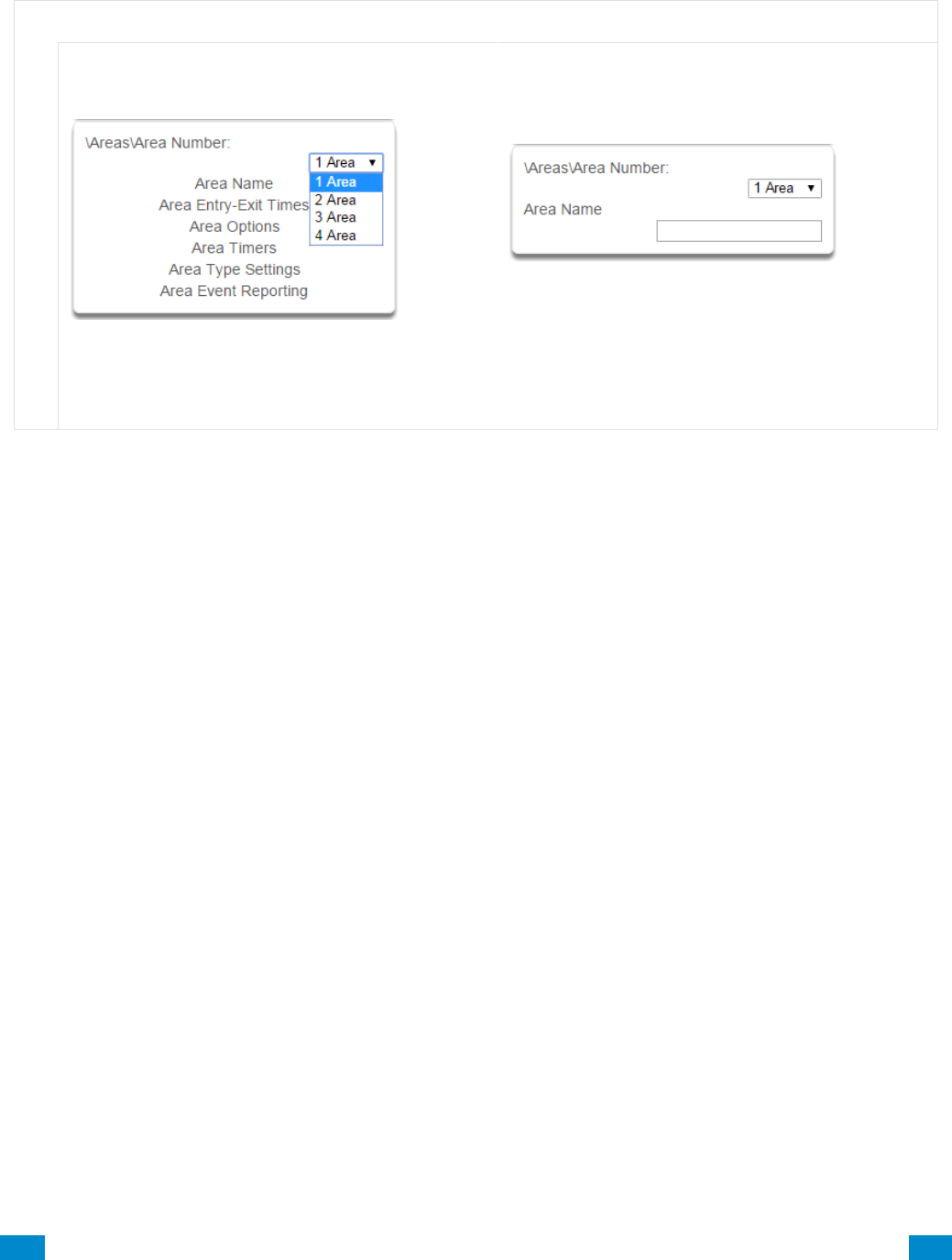
...C... 97 P/N 466-5261 • REVA • ISS 11NOV16 UltraSync Modular Hub Reference Manual ©2016 United Technologies Corporation .... .I.....
6.3 Advanced Programming, Areas
Click the Advanced bar and select Areas from the menu to program area options.
A r e a s S u b m e n u s
A r e a s S u b m e n u s
1 Area Number
Depending on the model, the system can support
up to 96 areas. Each area is identified by a unique
area number, which cannot be altered, and remains
as the key reference for each area.
2 Area Name
Each area can be configured with a custom 32
character name. The area name is displayed
wherever an area is referenced on the system.
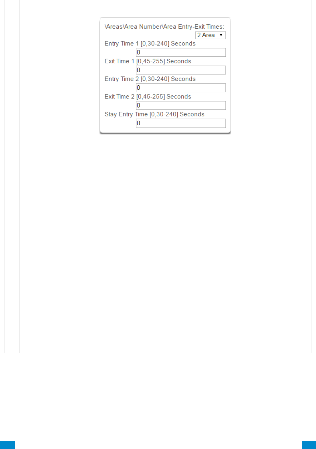
...C... 98 P/N 466-5261 • REVA • ISS 11NOV16 UltraSync Modular Hub Reference Manual ©2016 United Technologies Corporation .... .I.....
A r e a s S u b m e n u s
3 Area Entry-Exit times
The system uses the area entry and exit timers to delay the activation of an alarm event when entry/exit
sensor types are activated.
When an area is turned on, it will start an Exit 1 timer. While an Exit 1 timer is running – Entry 1, Entry 2,
and Follower sensor types will not create an alarm.
When the Exit 1 timer expires it will start the Exit 2 timer. While an Exit 2 timer is running – Entry 2
sensors will not create an alarm.
Once all exit delays are expired, an activation on an Entry 2 sensor type will start an Entry delay with the
Entry 2 time, and an activation of an Entry 1 sensor type will start an Entry delay with the Entry 1 time.
If an entry delay is running and a sensor is activated with an entry time that is less than the time
remaining, the timer will be reduced to the time of that new sensor.
When configuring Area 2 and above, the Entry and Exit times default to 0. When the Entry and Exit times
are set to 0, the system uses the Entry and Exit times configured for Area 1. A non-0 value will use that
value for the Entry or Exit time.
Activation of a Follower sensor while an entry timer is not running will create an instant alarm.
If a sensor is in more than 1 area, the sensor will use the have the longest entry and exit delay time of the
programmed area. If an area greater than 1 has the time set to 0, that area will use the time programmed
in Area 1.
Stay Entry Time
The stay entry time is the entry warning time that applies to all sensors armed in the stay mode.
This stay entry time only applies to Entry/Exit zones.
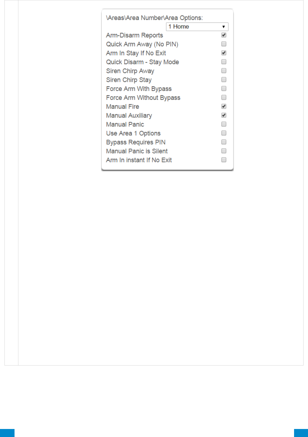
...C... 99 P/N 466-5261 • REVA • ISS 11NOV16 UltraSync Modular Hub Reference Manual ©2016 United Technologies Corporation .... .I.....
A r e a s S u b m e n u s
4 Area Options
1. Arm/Disarm Reports
If enabled, this area will send open and close reports via one or more appropriately configured channels.
2. Quick Arm Away (No PIN)
If enabled, this area can be armed in away mode via a single away mode key press. When an area is
armed via quick away mode, the closing user number is the default user of 999.
3. Arm In Stay If No Exit
If enabled, Arm In Stay If No Exit will cause this area to arm in stay mode even when a user arms it in
away mode, providing that an entry 1 or entry 2 sensor type is not triggered during the exit delay.
4. Quick Disarm - Stay Mode
If enabled, this will allow the stay mode to be disarmed by pressing the stay key on the keypad. This is
only possible if there is no alarm active and the stay entry delay is currently running.
At the end of the stay entry delay or if there is an area alarm, the stay mode can only be disarmed via a
valid user PIN.
5. Siren Chirp Away
If enabled, the system will activate the siren (Output 1) briefly each time this area is set in away mode or
disarmed with a key-switch or wireless keyfob. By default Output 1 is programmed to chirp.
6. Siren Chirp Stay
If enabled, the system will activate the built-in siren briefly each time this area is set in stay mode with a
key-switch sensor or wireless keyfob.

...C... 100 P/N 466-5261 • REVA • ISS 11NOV16 UltraSync Modular Hub Reference Manual ©2016 United Technologies Corporation .... .I.....
A r e a s S u b m e n u s
7. Force Arm With Bypass
If enabled, the area can be armed even if sensors are not ready. Any sensors that are not ready will
automatically be bypassed. The bypass will be logged in the event history.
The automatic bypass will be applied when the sensor is capable of causing an alarm condition due to a
state change such as an area arming, schedule or action. This avoids false alarms.
If an auto-bypassed sensor becomes ready after it is armed, that sensor will automatically remove the
bypass, log the bypass restore, and optionally report the bypass restore.
Individual sensors can be made “force armable with auto-bypass” by leaving this area option off, then
enabling Forced Arm Enable in Sensor options, and enabling Sensor Inhibit (Bypass) in the Sensor Type
Profile.
8. Force Arm Without Bypass
If enabled, the area can be armed even if sensors are not ready. Any sensors that are not ready will NOT
be automatically be bypassed and may cause an alarm condition because they could still be in a not ready
state once the area becomes armed.
This option is overridden if the Force Arm With Bypass is enabled.
Individual sensors can be made “force armable without auto-bypass” by leaving this area option off, then
enabling Forced Arm Enable in Sensor options, and disabling Sensor Inhibit (Bypass) in the Sensor Type
Profile.
9. Manual Fire
If enabled, the manual fire button will be enabled on keypads. Press and hold for 2 seconds to send a fire
event. Default is off.
10. Manual Auxiliary
If enabled, the manual auxiliary button will be enabled on keypads. Press and hold for 2 seconds to send
an auxiliary event. Default is off.
11. Manual Panic
If enabled, the manual panic button will be enabled on keypads. Press and hold for 2 seconds to send a
panic event. Default is off.
12. Use Area 1 Options
If enabled, the selected area will use the options chosen for Area 1. The panel ignores all other selections
made; it overrides them to instead use the options chosen for Area 1. Default is on.
13. Bypass Requires PIN
If enabled, a valid PIN code with access to this area is required to bypass sensors in this area.
14. Manual Panic is Silent
If enabled (in Settings), manual panic alarms will not trigger an audible alarm.
15. Arm In instant If No Exit
If enabled, this area will arm in Stay Instant mode when attempting to arm in Away mode and there is no exit.
...C... 101 P/N 466-5261 • REVA • ISS 11NOV16 UltraSync Modular Hub Reference Manual ©2016 United Technologies Corporation .... .I.....
A r e a s S u b m e n u s
Notes on Force Arming, Bypass, and Auto-Bypass
To arm an area it must first be “Ready to Arm”. This means all sensors in that area must be closed.
For example, if the front door is open, then a user would need to close it first and ensure there is no
movement in the reception area. This provides the Ready to Arm status in Area 1 that is needed before
attempting to arm. This is not always user friendly or practical.
The term force arm refers to the ability to arm an area even though sensors are not ready. It is usually
only used with motion sensors as these are self-restoring and will be restored by the time the exit delay
ends (e.g. the person arming the system leaves the building causing the Reception PIR to restore.)
If the front door is not closed properly then Area 1 would go into alarm at the end of the Exit time. To
avoid this false alarm we enable “Force Arm With Auto-Bypass” so all sensors that are not closed (i.e.
not ready) by end of the exit time will be “Auto-Bypassed”.
If after the Area is armed, that sensor restores (e.g. the person double checks and secures the front
door) then the Auto-Bypass will be removed from the sensor and it will be active. If subsequently the
sensor is triggered then Area will go into alarm.
Auto-bypass will be applied (if enabled, and if necessary) to a sensor whenever a change in state
occurs that would result in an alarm condition. These include arming an area with a not-ready sensor, a
sensor changing profile, Arm-Disarm function, or due to an action or schedule.
Enabling Auto-Bypass for the area will apply the feature to all sensors in that area as well.
In general disabling “Sensor Auto-Bypass” is not recommended because of the potential to create a
false alarm but there are applications where it is desired. Use “Force Arm Without Auto-Bypass” at
the area level to prevent sensors from being auto-bypassed when Force Armed.
AREA 1 - Office
[ ] Force Arm With Auto-Bypass
[ ] Force Arm Without Auto-Bypass
SENSOR 1 – Door Reed Switch
SENSOR TYPE
[ ] Sensor Auto-Bypass
SENSOR OPTIONS
[ ] Force Armed Enabled
[ ] Bypass
SENSOR 2 – Reception PIR
SENSOR TYPE
[ ] Sensor Auto-Bypass
SENSOR OPTIONS
[ ] Force Armed Enabled
[ ] Bypass
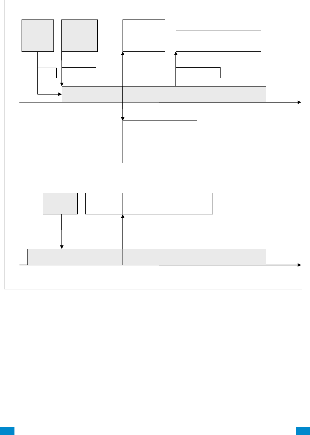
...C... 102 P/N 466-5261 • REVA • ISS 11NOV16 UltraSync Modular Hub Reference Manual ©2016 United Technologies Corporation .... .I.....
A r e a s S u b m e n u s
Auto Arm
Warning
Exit
Time
Area Disarmed
Entry/Exit
Sensor
Tripped
Alarm if valid
code not
entered
Area Armed
Auto-bypassed sensors restored
Bypassed sensors restored
All
Sensors
Ready =
Area
Ready
Auto Arm
Warning
Exit
Time
Area Armed
Sensors Not
Ready =
Area Not
Ready to
Arm
Force Arm
If Auto-Bypass
enabled then
auto-bypass all
not ready
sensors
Else Alarm
Auto-bypassed sensor is restored
Bypassed sensors remain bypassed
Sensor restores
If “Arm In Stay If No Exit”
disabled, and entry/exit zone
tripped, Arm in Away mode
If “Arm In Stay If No Exit”
enabled, and entry/exit zone
not tripped, Arm in Stay mode
Arm
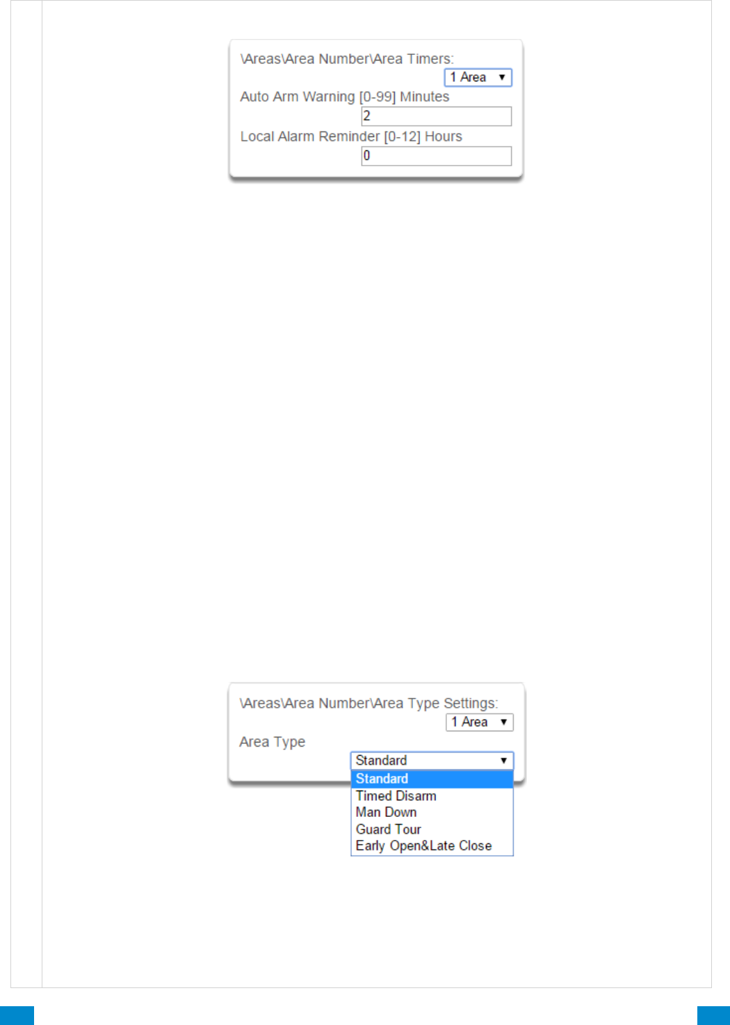
...C... 103 P/N 466-5261 • REVA • ISS 11NOV16 UltraSync Modular Hub Reference Manual ©2016 United Technologies Corporation .... .I.....
A r e a s S u b m e n u s
5 Area Timers
Auto Arm Warning
If the area type is Standard and Arm / Disarm is configured, this timer delays arming by the minutes
entered.
If the area type is Timed Disarm, Man Down, or Guard Tour, this setting is a warning time given to a user
once the user’s Disarm Time, Man Down Time, or Guard Tour Time has expired. During this warning time
a user can cancel the automatic re-arming and event report by entering their code, this will also restart the
appropriate user timer. At the end of the warning time the system will re-arm the area and send the
appropriate event (closing, man down, guard tour fail).
If the area type is Early Open & Late Close, this timer sets the period after the start (opening) and after the
end (closing) of the area type schedule that the area can be disarmed or armed. Otherwise an early to
open or late to close report will be sent if enabled in user permissions. Fail to open and fail to close report
will be sent if Arm-Disarm Reports is enabled in area options.
Valid values are from 0 to 99 minutes
Local Alarm Reminder
If set, the local alarm reminder is the period in minutes between 0 and 999 that may elapse between
actioning a local alarm and the local alarm reactivating if that sensor has remained open.
For example if a smoke detector is removed to change the battery the tamper will trip; if a user resets the
alarm on the system but does not replace the smoke detector within the local alarm reminder time, then
the fire alarm tamper will retrigger.
6 Area Type
Standard
The area functions as normal.
Timed Disarm
Timed disarm is used when an authorised user can disarm an area for a predetermined period of time. At
the end of this disarm time the area will start the auto-arm process ensuring that the area is not accidently
left disarmed.

...C... 104 P/N 466-5261 • REVA • ISS 11NOV16 UltraSync Modular Hub Reference Manual ©2016 United Technologies Corporation .... .I.....
A r e a s S u b m e n u s
The following conditions must be true before a timed area disarm function will occur.
a. The area type must be set to Timed Disarm.
b. The area type schedule must be active.
c. The user’s active profile’s permission must have:
i. This area set in the permission’s timed disarm area group.
ii. The permission must be in schedule.
iii. The permission’s Area Type Override must NOT be set.
At the end of the user’s disarm time, the Area Type Delay will activate for the set period. At the end of the
Area Type Delay period the area will arm and start the Exit Delay and if configured, report a closing using
via the last user number to have time disarmed the area.
At anytime during the timed disarm period, authorised users with Area Type Override set in their active
profile can cancel the disarm time period by arming or disarming the area.
The user’s permission determines how long the area will be disarmed for.
Man Down
Man down is used when an authorised user(s) is working in a hazardous area (or the like), and there is a
requirement that the user(s) regularly “check-in” to notify others that the user(s) is safe. If the authorised
user(s) fails to perform this action the system can set an audible warning and send a report.
The following conditions must be true before man down function will occur.
a. The area type must be selected to man down.
b. The area type schedule must be active (after the start time and before the end time).
c. The user’s active profile’s permission must have:
i. This area set in the permission’s man down group.
ii. The permission must be in schedule.
iii. The permission’s Area Type Override must NOT be set.
The man down timer is set in the user’s permission.
At the end of the user’s man down time, the Area Type Delay will activate for the set period. At the end of
the Area Type Delay period the area will arm and if configured, report a man down alarm. At anytime
during the man down period, authorised users with the Area Type Override set in their active profile will
cancel the man down time period by disarming or disarming the area.
Guard Tour
Guard tour is used when an authorised user(s) (such as a guard) is required to regularly “check-in” to
notify others that they have physically attended to a location(s) on the site. If the authorised user(s) fails to
perform this action the system can set an audible warning and report a “Guard Tour Fail” event.
The following conditions must be true before guard tour function will occur.
a. The area type must be selected to guard tour.
b. The area type schedule must be active (after the start time and before the end time).
c. The user’s active profile’s permission must have:
i. This area set in the permission’s guard tour group.
ii. The permission must be in schedule.
iii. The permission’s Area Type Override must NOT be set.
The guard tour time is set in the user’s permission.
At the end of the user’s guard tour time, the Area Type Delay will activate for the set period and keypad
sounder will be active. At the end of the Area Type Delay period the area will arm and if configured, report
a Guard Tour Fail alarm. At anytime during the guard tour period, authorised users with the Area Type
Override set in their active profile will cancel the guard tour time period by disarming or disarming the
area.
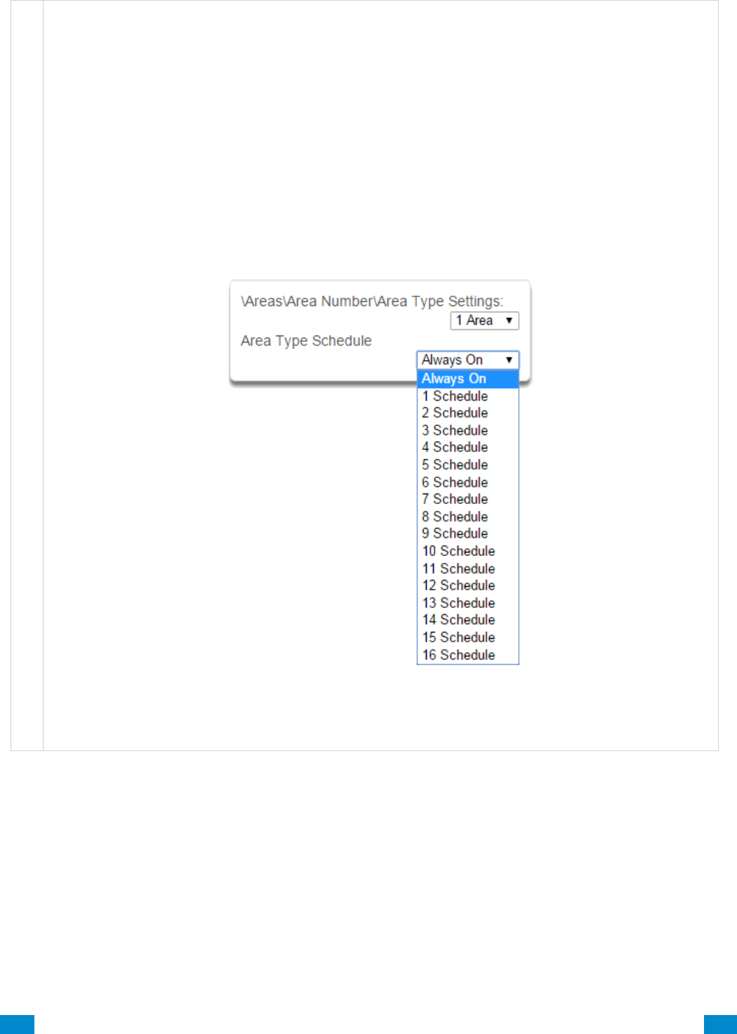
...C... 105 P/N 466-5261 • REVA • ISS 11NOV16 UltraSync Modular Hub Reference Manual ©2016 United Technologies Corporation .... .I.....
A r e a s S u b m e n u s
Early Open/Late Close
If the area type is Early Open & Late Close, the Auto Arm Warning sets the period after the start (opening)
and the end (closing) of the area type schedule that the area must be either disarmed or armed to avoid
an exception report. If the area is not disarmed (opened) within the opening window a Fail to Open
message is sent. When the area is subsequently disarmed, a Late Open message is sent. If the area is
not armed (closed) within the closing window a Fail to Close message is sent. When the area
subsequently armed, a Late Close message is sent.
For example, if the area type schedule is set between 8:00 AM (opening time) and 5:00 PM (closing time)
and the Area Type Delay is set to 15 minutes; then the area must be disarmed between 8:00 AM and 8:15
AM otherwise if it is disarmed before 8:00 AM it is an early open, if it is disarmed after 8:15 AM it is late to
open. Likewise the area must be armed between 5:00 PM and 5:15 PM otherwise if it is armed before
5:00 PM it is an early close, if it is armed after 5:15 PM it is late to close.
7 Area Type Schedule
One of 96 configurable schedules can be allocated to the area type schedule. The area type schedule
determines the schedule that the selected area type is active. Area types are not active when the
schedule is not active. If an area type schedule is disabled (always active) that area will always have the
type characteristics programmed in Area Type.
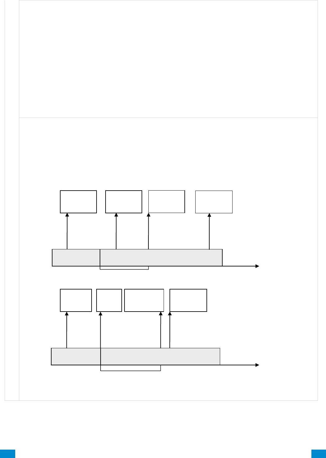
...C... 106 P/N 466-5261 • REVA • ISS 11NOV16 UltraSync Modular Hub Reference Manual ©2016 United Technologies Corporation .... .I.....
A r e a s S u b m e n u s
Area Type Delay
If the area type is Standard and Arm / Disarm is configured, this timer delays arming by the minutes
entered.
If the area type is Timed Disarm, Man Down, or Guard Tour, this setting is a warning time given to a user
once the user’s Disarm Time, Man Down Time, or Guard Tour Time has expired. During this warning time
a user can cancel the automatic re-arming and event report by entering their code, this will also restart the
appropriate user timer. At the end of the warning time the system will re-arm the area and send the
appropriate event (closing, man down, guard tour fail).
If the area type is Early Open & Late Close, this timer sets the period after the start (opening) and after the
end (closing) of the area type schedule that the area can be disarmed or armed. Otherwise an early to
open or late to close report will be sent if enabled in user permissions. Fail to open and fail to close report
will be sent if Arm-Disarm Reports is enabled in area options.
Example
Area Type – Early Open & Late Close
Area Type Schedule – 8:00 to 17:00
Area Type Delay – 15 min
User Permissions – Options – Open/close report, Early open report, Late close report
Area Options – Arm-Disarm Reports
Open Window
Area is Armed
8:15
17:00
Area Type
Delay
Close Window
Area is Disarmed
Send Early
Opening
Send
Close
Send Late
Closing
Open Window
Area is Disarmed
Send Fail to
Open
Area Armed
8:00
17:15
Area Type
Delay
Area Armed
Send Fail to
Close
Send Open
Area Disarmed
Automatically
sent
Automatically
sent
Send
Early
Close
Send Late
Open
Close Window
Area is Armed
Area Disarmed
Area Disarmed
Area Armed
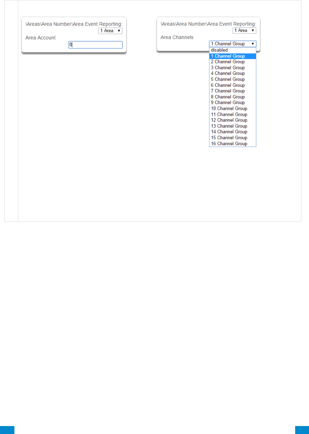
...C... 107 P/N 466-5261 • REVA • ISS 11NOV16 UltraSync Modular Hub Reference Manual ©2016 United Technologies Corporation .... .I.....
A r e a s S u b m e n u s
8 Area Event Reporting/Account
9 Area Event Reporting/Channels
If set, the area account code is a system unique
4 to 10 digit code (format dependent) used to
associate area related alarm reporting events to
this area. If the area account code is equal to the
default of 0, the channel account code will be
used for this area’s alarm reporting events. If the
channel account code is equal to the default of 0,
the channel 1 account code is used. If the
channel 1 account code is 0 then the account will
be sent as 0.
The channel group determines which communicator
channel(s) area events will be reported to. If the tick
box corresponding to one of the 16 reporting channels
is checked, area events will always be reported to this
channel. It is referred to as a primary reporting
channel. If a report is unsuccessful to a particular
primary channel it will attempt that channel’s backup
channels if there are any.
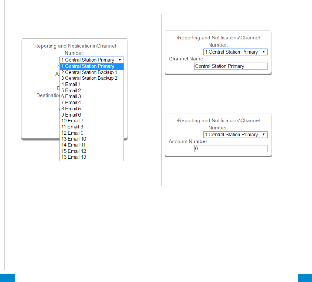
...C... 108 P/N 466-5261 • REVA • ISS 11NOV16 UltraSync Modular Hub Reference Manual ©2016 United Technologies Corporation .... .I.....
6.4 Advanced Programming, Reporting and Notifications
Click the Advanced bar and select Reporting and Notification from the menu to program
reporting and notification options.
The system can support a total of 16 channels; each channel is a communication path for
events to be sent from the system to a selected destination.
Default configuration reserves Channels 1 – 3 for UltraSync format, Channels 4 – 16 are
Email format.
Email is a “best-effort” system and there is no guarantee messages will be delivered by the
network. When the network is busy, messages can be dropped. Central control room
monitoring is highly recommended as each event is acknowledged on receipt to ensure an
appropriate response can be made.
Installers have access to setup/modify all channels (1-16). Master Users have access to
channels 7-16, which are used for email notifications. Standard users do not have access to
channels.
R & N S u b m e n u s
Reporting & N o t i f i c a t i o n s S u b m e n u s
1 Channel Number
The system can support a total of 16 channels.
Each channel is identified by a unique channel
number, which cannot be altered, and remains as
the key reference for each channel.
Channel 1 and channels 4-16 are configured as
primary reporting paths by default. Channel 1
reports to UltraSync by default. Use as Backup as
the Format selection has the effect of disabling
reporting of a primary channel. The Format must be
selected to a value other than Use as Backup to
enable reporting. Channels 4-16 are configured as
email reporting paths by default.
2 Channel Name
Custom names of the selected channel can be
created here.
3 Account Number
This is the Account Number that will be reported
with the event in email reports. When UltraSync
format is selected, this field will not be used.
Channels 2 and 3 are configured as backup
reporting paths by default. Channel 2 is set to
disabled and channel 3 is set to back up channel 2
by default. Note that the primary channel must set
the Next Channel for back up reporting to function.
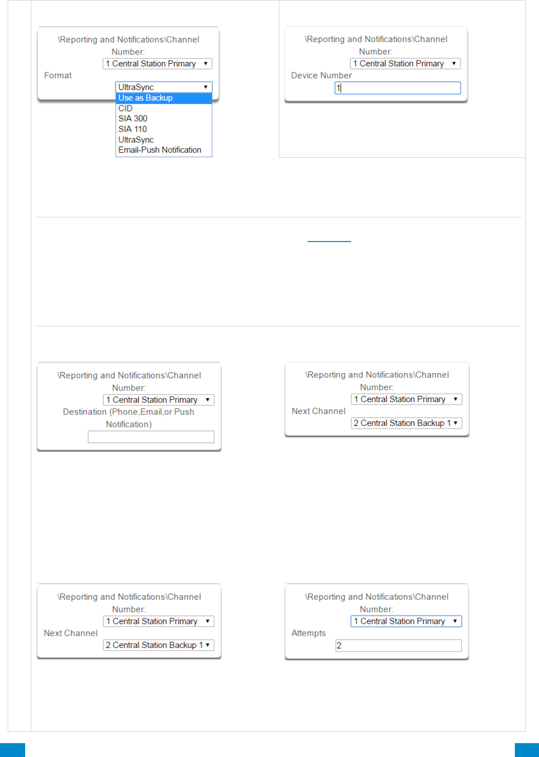
...C... 109 P/N 466-5261 • REVA • ISS 11NOV16 UltraSync Modular Hub Reference Manual ©2016 United Technologies Corporation .... .I.....
Reporting & N o t i f i c a t i o n s S u b m e n u s
4 Format
5 Device Number
Reserved for future use
Format is the communication format for the selected channel. Selections available in the drop down
menu are shown. When Use as Backup is selected, the backup path will utilize the primary channel’s
format. Note that the primary channel must set the Next Channel for back up reporting to function.
Note: Selecting CID or SIA enables PSTN reporting. If utilizing PSTN reporting you need to enter a
destination phone number. This is available in the Settings, Channels Menu.
When UltraSync is selected as the Format, the reporting path will be over the Ethernet connection. When
a cellular module is installed, it will automatically act as a failover path if the Ethernet path fails. There is
no requirement to configure the cellular path as a backup reporting path.
When Email is selected as the Format, the reporting will be directed to the configured email address.
(Ethernet or Cellular connection required)
6 Destination Phone/Email/Push
The destination of the notifications.
7 Next Channel 1-16
If the channel selected is unable to deliver the
event to the selected destination, the system will try
to use this backup channel instead. The Next
Channel specified here must be greater than the
Channel Number.
A number lower than the current Channel Number
will end the chain. This is to prevent accidental
programming of endless loops.
8 Event List 1-16
Select the pre-programmed list of events that will be
sent via this channel. The specific events in each
event list are programmed.
9 Attempts
Enter the number of times the system should try to
send the events to the UltraSync server. After the
number of attempts has been exhausted the
system will try the Next Channel if specified.
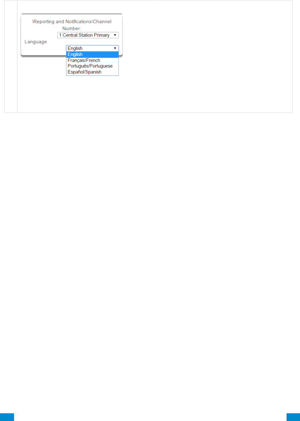
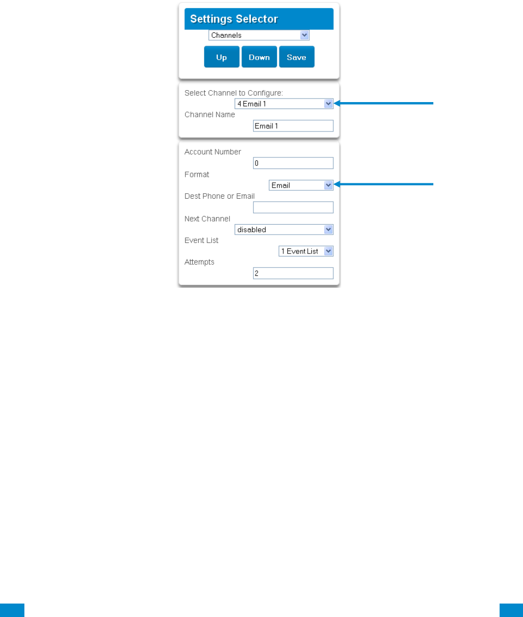
...C... 111 P/N 466-5261 • REVA • ISS 11NOV16 UltraSync Modular Hub Reference Manual ©2016 United Technologies Corporation .... .I.....
Configure Email Reporting
1. Login to the UltraSync Web Server or UltraSync app. Use an Installer or Master user
account.
2. Press Settings.
3. Select Channels in the drop down menu.
4. Press Select Channel to Configure where the Format is already set to Email.
5. Enter an email address.
6. Select an Event List.
7. Enter a Channel Name for future reference.
8. Press Save.
Installer and Master User types can customize Event Lists for selective reporting.
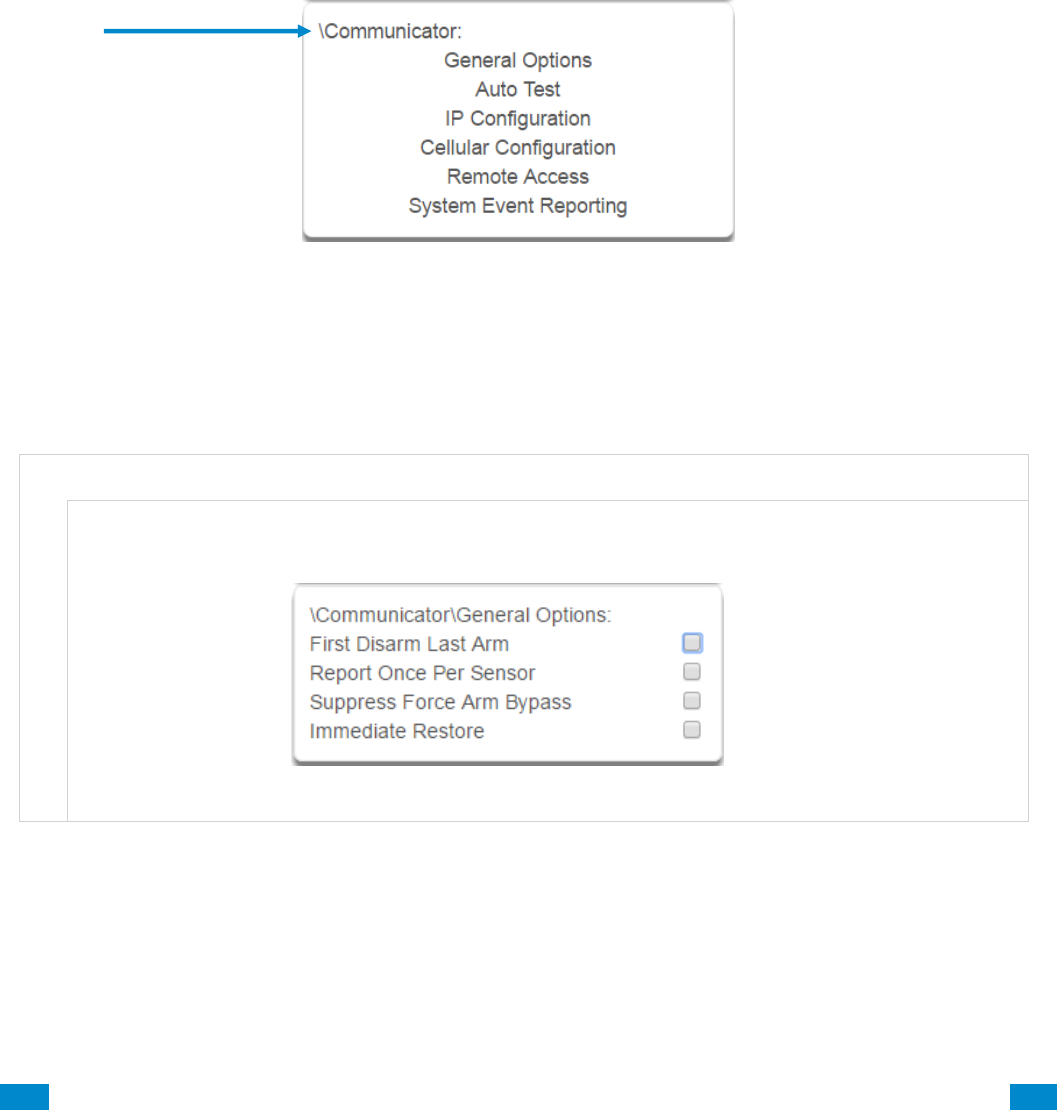
...C... 112 P/N 466-5261 • REV D ISS 17NOV17 UltraSync Modular Hub Reference Manual ©2016 United Technologies Corporation .... .I.....
6.5 Advanced Programming, Communicator
Click the Advanced bar and select Communicator from the menu to program communicator
options.
The system’s Communicator is a core component of the system used in conjunction with the
Channels feature to report events to a monitoring company or third party. In this menu you
can configure the settings for various methods of reporting.
C o m m u n i c a t o r S u b m e n u s
1 General Options
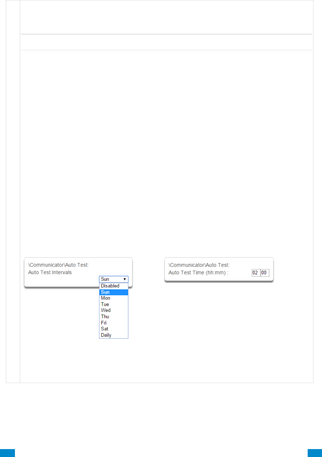
...C... 113 P/N 466-5261 • REV D ISS 17NOV17 UltraSync Modular Hub Reference Manual ©2016 United Technologies Corporation .... .I.....
Communicator Submenus
1. First Disarm Last Arm
If enabled, the system will only send a closing report when the last area is armed.
Note: The last area to arm must have open/close reports enabled. The system will only send an opening
report when the first area is disarmed.
This feature is used in place of Individual area Open and close. If you enable open and close in the area
you will get both individual open and close and System open close
2. Report Once Per Sensor
If enabled, this will limit reporting to only once per sensor each time you arm or disarm an area. This stops
the control room or reporting destination to be flooded by multiple reports that the same sensor is being
activated (for example the intruder may be moving around and is being picked up by the sensor on that
zone).
3. Suppress Force Arm Bypass
If enabled, the system does not send bypass reports when a sensor is forced armed.
If not enabled, when a sensor is forced armed and it remains in a state of creating an alarm, bypass
reports are sent at the end of exit time. For example this would occur if it remains open at the end of the
exit time, or due to change of sensor type caused by a schedule.
If forced armed sensors re-close during the armed period, bypass restores are sent.
4. Immediate Restore
If enabled, the system will immediately send all restorals as the sensor reports the event.
If not enabled, the system will send restoral events all at the same time when the marea is disarmed.
2 Auto Test/Intervals
Set day of the week to send an automatic test
report to the system channel group .
(Communicator\System Event Reporting\System
Channels). You may also set auto-test to Daily.
3 Auto Test/Time
Enter the time at which the automatic test report
should be sent. This should be in 24-hour format. For
example 18:00.
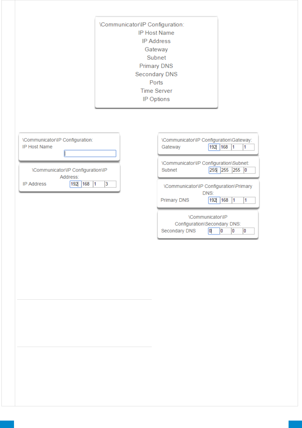
...C... 114 P/N 466-5261 • REV D ISS 17NOV17 UltraSync Modular Hub Reference Manual ©2016 United Technologies Corporation .... .I.....
Communicator Submenus
4 IP Configuration
5-6 IP Config Detail
IP Host Name
The default IP Host Name is xgen. To access the
web server without an IP address, simply type
http://xgen into the web browser. Some browsers to
not require http://.
To change the IP Host Name, enter a new IP Host
Name and hit the Save button. The saved change
does not take effect until you log out of the Web
server. PC’s typically cache this address for about
10 minutes. If you used the default xgen host name
and then change it, the new host name will not be
useable for this time frame.
Note: This feature is not supported with Internet
Explorer. This only works on the local LAN and with
a Windows® PC, or an Apple MAC. The PC or
MAC must have Netbios Name Service (NBNS)
enabled. It does not work remotely over the
internet. Remote access to the server is supported
via the UltraSync Portal.
IP Address
The IP address assigned to the communicator to
enable it to connect on to the local LAN. This will
allow you access to the embedded web server from
a web-enabled device to program and view the
status of the system. It is also used for alarm
reporting.
7-10 IP Config Detail
Gateway
If required, the IP address of the router which is
needed when remote IP communications are used .
Subnet
The subnet mask for the network.
For example, 255.255.255.0 is the network mask for
192.168.1.0/24.
Primary DNS
The IP address of the Primary Domain Name Server.
The DNS is used to translate host names for time
servers and UltraSync servers.
Secondary DNS
The IP address of the Secondary Domain Name
Server, used if the Primary DNS is not available.
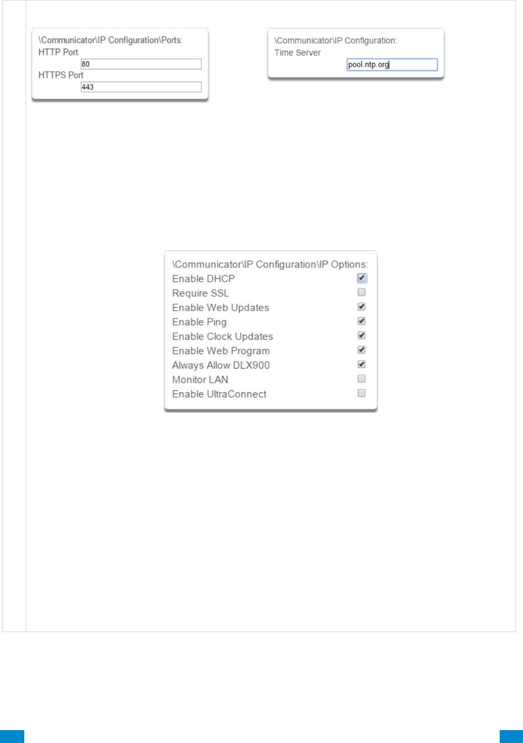
...C... 115 P/N 466-5261 • REV D ISS 17NOV17 UltraSync Modular Hub Reference Manual ©2016 United Technologies Corporation .... .I.....
C o m m u n i c a t o r S u b m e n u s
11 Ports
The ports that the computer needs to communicate
with the system.
Defaults:
HTTP Port = 80
HTTPS Port = 443
12 Time Server
Enter the URL or IP address of a time server to allow
the system to automatically update and synchronise its
clock without user intervention. The default is
pool.ntp.org
13 IP Options
1. Enable DHCP
Allow the system to be automatically assigned an IP address by the network.
2. Require SSL
Feature no longer supported. Leave unchecked.
3. Enable Web Updates - RESERVED
Allows the system to update the web pages via a network. Go to Hostname/mpfsupload to update the web
pages served by the system. Does not update firmware.
4. Enable Ping
Allows the system to respond to the PING command.
5. Enable Clock Updates
Allows the system’s internal clock to synchronise with the internet time server specified .
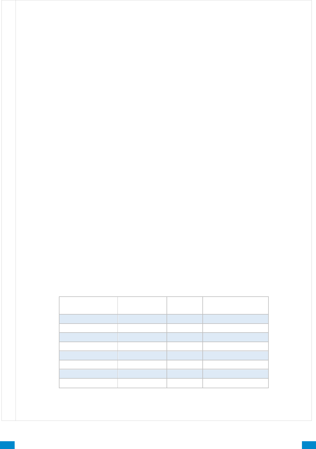
...C... 116 P/N 466-5261 • REV D ISS 17NOV17 UltraSync Modular Hub Reference Manual ©2016 United Technologies Corporation .... .I.....
Communicator Submenus
6. Enable Web Program
Enabling this option will cause UltraSync Web Server and UltraSync app to always display Installer menus
regardless of if the panel is in program mode or not.
Disabling this option will hide the Installer menus on UltraSync Web Server and UltraSync app unless
program mode is active. This provides greater security by keeping web programming disabled unless a user
on site with physical access to the keypad enters program mode with a valid PIN code.
The system will be in program mode if a user gains authorized access to the program menu via the keypad.
UltraSync app requires the Web Access Code to access to the panel.
7. Always Allow DLX 900
Enabling this option will allow DLX 900 to connect at any time if the correct Download Access Code is
provided.
Disabling this option provides greater security by only allowing DLX 900 to connect when program mode is
active. This allows the system to have DL900 access disabled until a user on site with physical access to the
keypad enters program mode with a valid PIN code.
The system will be in program mode if a user gains authorized access to the program menu via the keypad.
8. Monitor LAN
When the Monitor LAN option is enabled the panel will monitor the Ethernet port for a valid Ethernet cable. If
the Ethernet cable is disconnected while this option is enabled, and the panel is unable to communicate, it
will log a Fail To Communicate event.
9. Enable UltraSync
This is an automatic feature. It is recommended you leave this setting on.
Enable this option to allow the system to send email reports via the UltraSync servers. This is independent of
the Web Access Passcode which when set to 00000000 will prevent the UltraSync app from connecting.
If any channel is set to Email format reporting, then the system will override this setting and allow email
reporting via UltraSync cloud servers.
If you wish to prevent connections to the system’s cloud servers, then uncheck this option and do not use the
UltraSync reporting format.
Reporting
Enabled*
Web Access
Passcode
Enable
UltraSync
Connection to
UltraSync Servers
No
00000000
No
No
No
00000000
Yes
Yes
No
non 00000000
No
Yes
No
non 00000000
Yes
Yes
Yes
00000000
No
Yes
Yes
00000000
Yes
Yes
Yes
non 00000000
No
Yes
Yes
non 00000000
Yes
Yes
* Includes email and UltraSync reporting for all channels
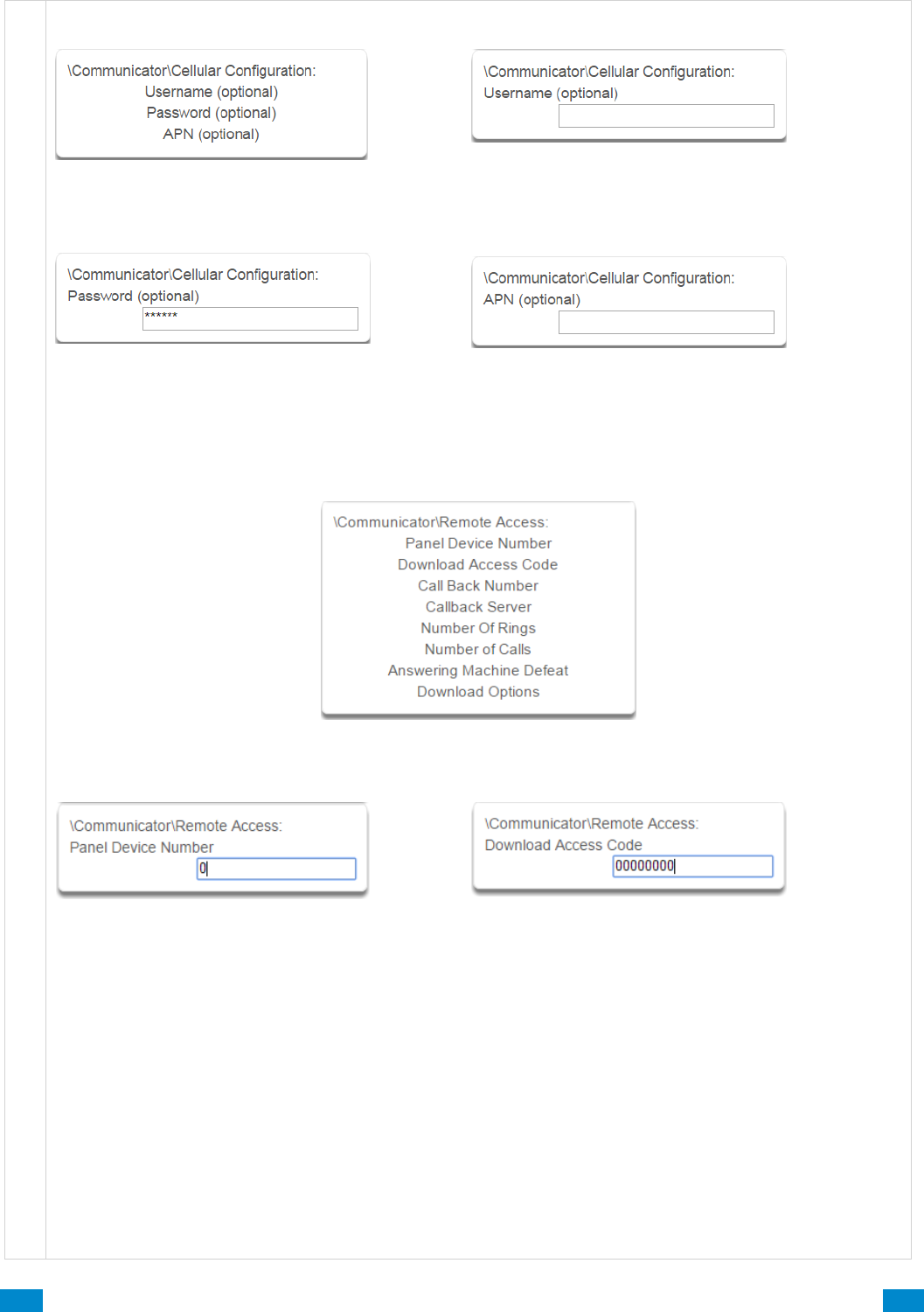
...C... 117 P/N 466-5261 • REV D ISS 17NOV17 UltraSync Modular Hub Reference Manual ©2016 United Technologies Corporation .... .I.....
Communicator Submenus
17 Cellular Configuration
18 Username (optional)
Optional username for APN. This is normally not used
unless a non-standard cellular SIM is utilized.
19 Password (optional)
Optional password for APN. This is normally not
used unless a non-standard cellular SIM is utilized
20 APN (optional)
Optional Access Point Name (APN) for the gateway
between the cellular network and the public Internet.
This is normally not used unless a non-standard
cellular SIM is utilized.
21 Remote Access
22 Panel Device Number
A number from 0 to 4,294,967,295 that must be
entered in to the desktop software for remote
access to take place.
23 Download Access Code
This is a variable length code for the computer user.
This code gives the DLX 900 software complete
authority over all menus including those that are
locked. For convenience DLX 900 will also try installer
and 9–7–1–3 to allow a connection for first time set up
if the Download Access Code does not work. This is
why changing the default installer PIN code is
important.
Changing this code may lock out your control room
monitoring service and prevent you from maintaining
your system. It is advised you contact your control
room before changing this code.
Users must have access to the Communicator menu in
order to change this setting. This can be programmed
in Menus, and assigning the “Advanced” menu.
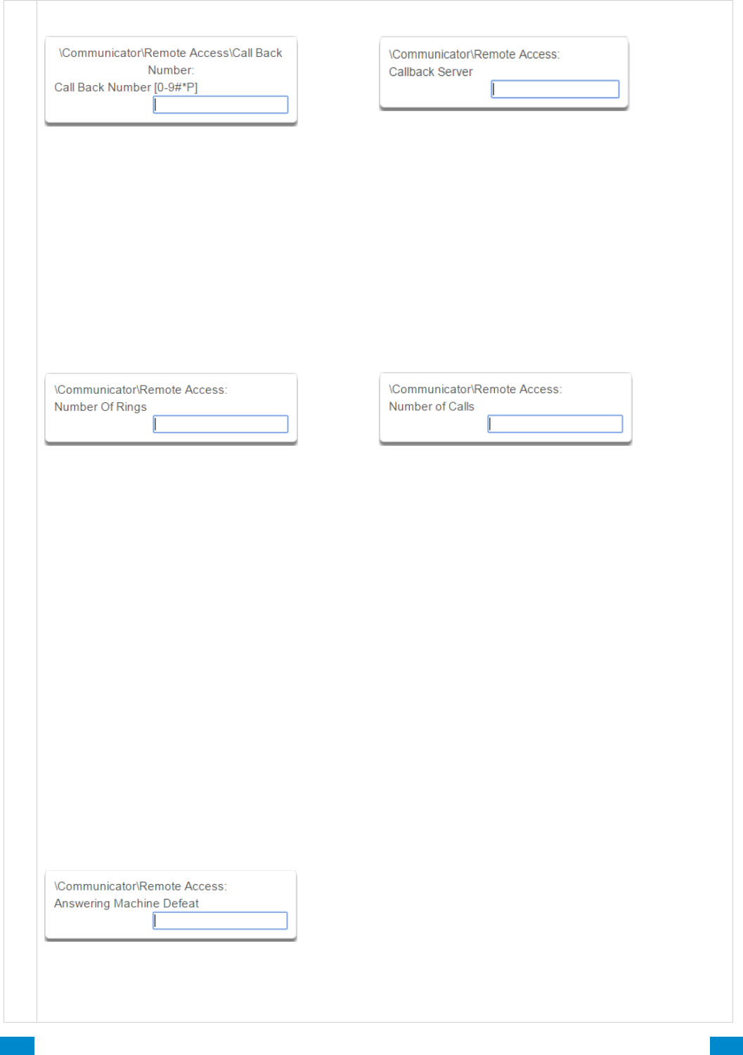
...C... 118 P/N 466-5261 • REV D ISS 17NOV17 UltraSync Modular Hub Reference Manual ©2016 United Technologies Corporation .... .I.....
Communicator Submenus
24 Call Back Number
If a telephone number is programmed into this
feature, and “Call Back Before Download” is
enabled, the system will disconnect for
approximately 10 seconds and then call this
number.
The system does not support pulse dialling. A one
second pause is entered by using a P.
IMPORTANT: the call back phone number should
always be reviewed for accuracy before
disconnecting!
25 Callback Server
If an IP address or host name is programmed into this
feature, and “Call Back Before Download Session” is
enabled, the system will disconnect for approximately
10 seconds and then connect to this IP address.
This should be the IP address of the computer where
DLX 900 is installed, not the IP address of the
system.
IMPORTANT: the call back IP address should always
be reviewed for accuracy before disconnecting.
26 Number of Rings
This contains the number of rings the panel must
detect before answering the telephone line when
initiating a download session. Answering machine
defeat does not need to be enabled.
A value of 1 to 15 can be entered in this segment.
If this ring count is reached on any individual call,
the panel will answer regardless of the call count or
number of calls programming.
Default = 8
27 Number of Calls
This contains the number of calls the panel must detect
before answering the telephone line when initiating a
download session. Answering machine defeat does not
need to be enabled.
A value of 1 to 15 can be entered in this segment. A
call is satisfied by one (1) or more rings, and then an
eight (8) second period of no ringing. The next call
must then be made within 45 seconds.
This location stands alone. If it still needed Number of
Rings it could be blocked by an answering machine.
This will answer on the first ring if the call count is
reached.
For example: If number of calls is set to 3. And you call
the premises and hang up after any number of rings,
wait at least 8 seconds, call again and hang up after
any number of rings, wait at least 8 seconds, and call
again (this is the third call) the panel will answer on the
third ring because the call count has reached the
Number of Calls programmed value.
If on any individual call the number of rings on that call
is reached, the panel will answer on that call regardless
of the call count.
Default = 0, system will pick up the call immediately.
28 Answering Machine Defeat
Answering Machine Defeat: Answering machines usually answer calls after a long ring period. The Answering
Machine Defeat feature prevents the answering machine from answering the call from the software by
making only short rings. If enabled, the system will always answer the call on the second call back. This
option is independent of Number of Calls and Number of Rings.
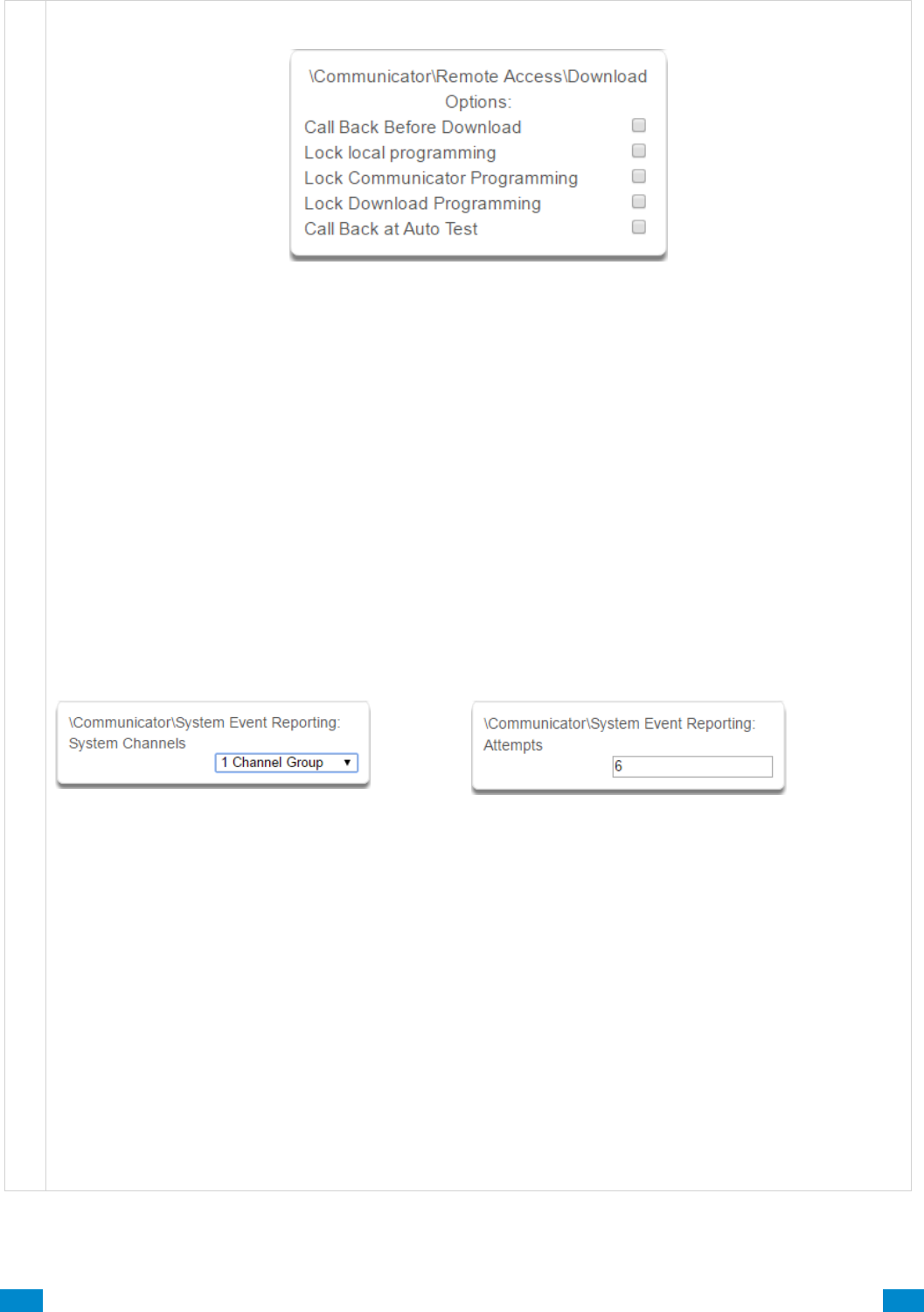
...C... 119 P/N 466-5261 • REV D ISS 17NOV17 UltraSync Modular Hub Reference Manual ©2016 United Technologies Corporation .... .I.....
Communicator Submenus
29 Download Options
1. Call Back Before Download
If a download is requested the system will hang up and make a call to the Call Back Number. This is to
increase the security of remote access.
2. Lock local Programming
Prevents changes to the system system via a keypad. All changes MUST be made using the remote access
software. This requires Download Access Code to be enabled.
3. Lock Communicator Programming
Prevents local programming of communicator features unless accessed by the Download Access Code.
This restricts programming of the communicator.
4. Lock Download Programming
Prevents the local programming of the Remote Access Menu without using the Download Access Code.
5. Call Back at Auto Test
When an auto test is initiated, perform a Call Back Server or Call Back Number to the number specified.
30 Event Reporting /Channels
Enter the Channel Group that the system will send
system events to.
31 Event Reporting /Attempts
This is the number of times the system will sequence
back to the primary channel if the backup channels all
fail. This applies to ALL communication attempts
including sensor and area events.
Example
If Channel 1 is the primary, and Channel 2 is the backup for Channel 1, then when both channels fail it will go
back to Channel 1. This setting controls how many times the system cycles back to Channel 1 before it gives
up.
The Channel Attempts setting controls how many times the system stays on the channel before switching to
the backup.
Always check the max. number of attempts on all channels to avoid unexpectedly high communication
charges.
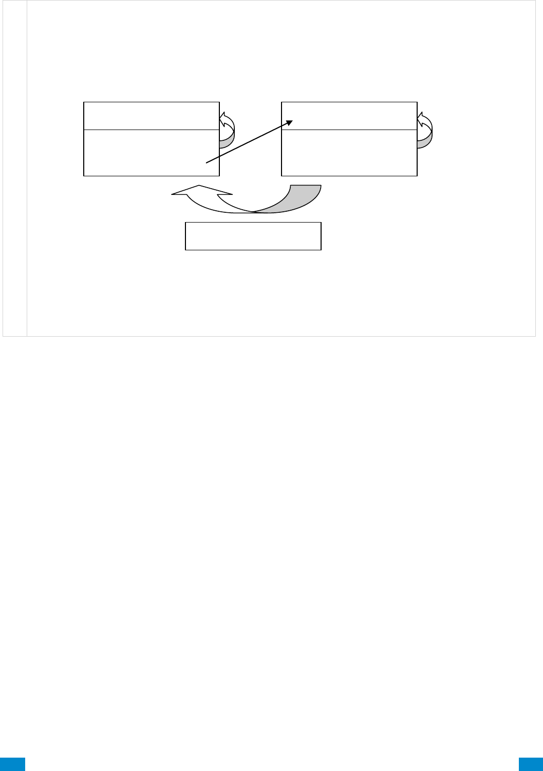
...C... 120 P/N 466-5261 • REV D ISS 17NOV17 UltraSync Modular Hub Reference Manual ©2016 United Technologies Corporation .... .I.....
Communicator Submenus
In the diagram below, the system will try Channel 1 3 times, switch to Channel 2 and try 2 times, then go
back to Channel 1. This sequence is repeated 2 times in total. In total there will be 10 attempts.
Channel 1
Channel Attempts = 3
Next Channel = 2
Channel 2
Channel Attempts = 2
Next Channel = 0
Report Attempts = 2
3 tries
2 tries
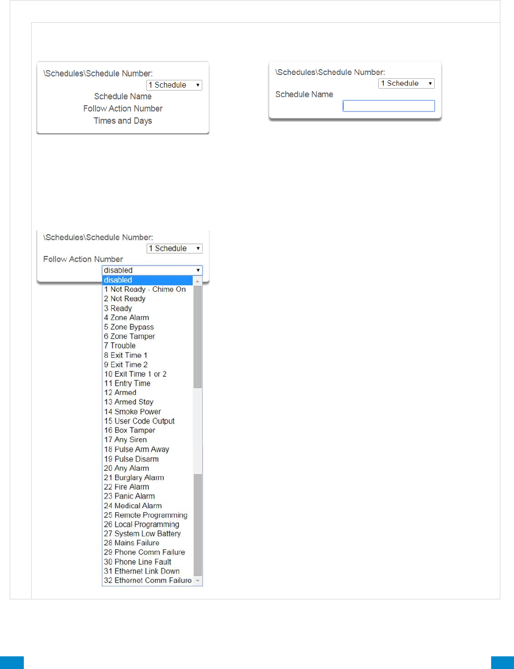
...C... 121 P/N 466-5261 • REV D ISS 17NOV17 UltraSync Modular Hub Reference Manual ©2016 United Technologies Corporation .... .I.....
6.6 Advanced Programming, Schedules
Click the Advanced bar and select Schedules from the menu to program schedule options.
S c h e d u l e s S u b m e n u s
S c h e d u l e s S u b m e n u s
1 Schedule Number
The system can support a total of 96 schedules.
Each schedule is identified by a unique schedule
number, which cannot be altered, and remains as
the key reference for each schedule.
2 Schedule Name
Each schedule can be configured with a custom 32
character name. The area name is displayed
wherever a schedule is referenced on the system.
3 Follow Action Number
If an action number is specified, then the schedule
becomes enabled when the action is true. When the
action becomes false, then the schedule becomes
disabled.
Schedules can be used to control various parts of
the system such as when a user’s permissions are
applied. The “Follow Action Number” option allows
you to use actions to control schedules.
The result is actions can control when permissions
are applied, when area types are applied, sensor
behaviors, when arm-disarm can occur, and when
scenes play.
This allows you to create conditional schedules that
only become active when certain conditions are met.
For example you could create a user that only
becomes active (because of the linked schedule)
under certain conditions like a fire alarm.
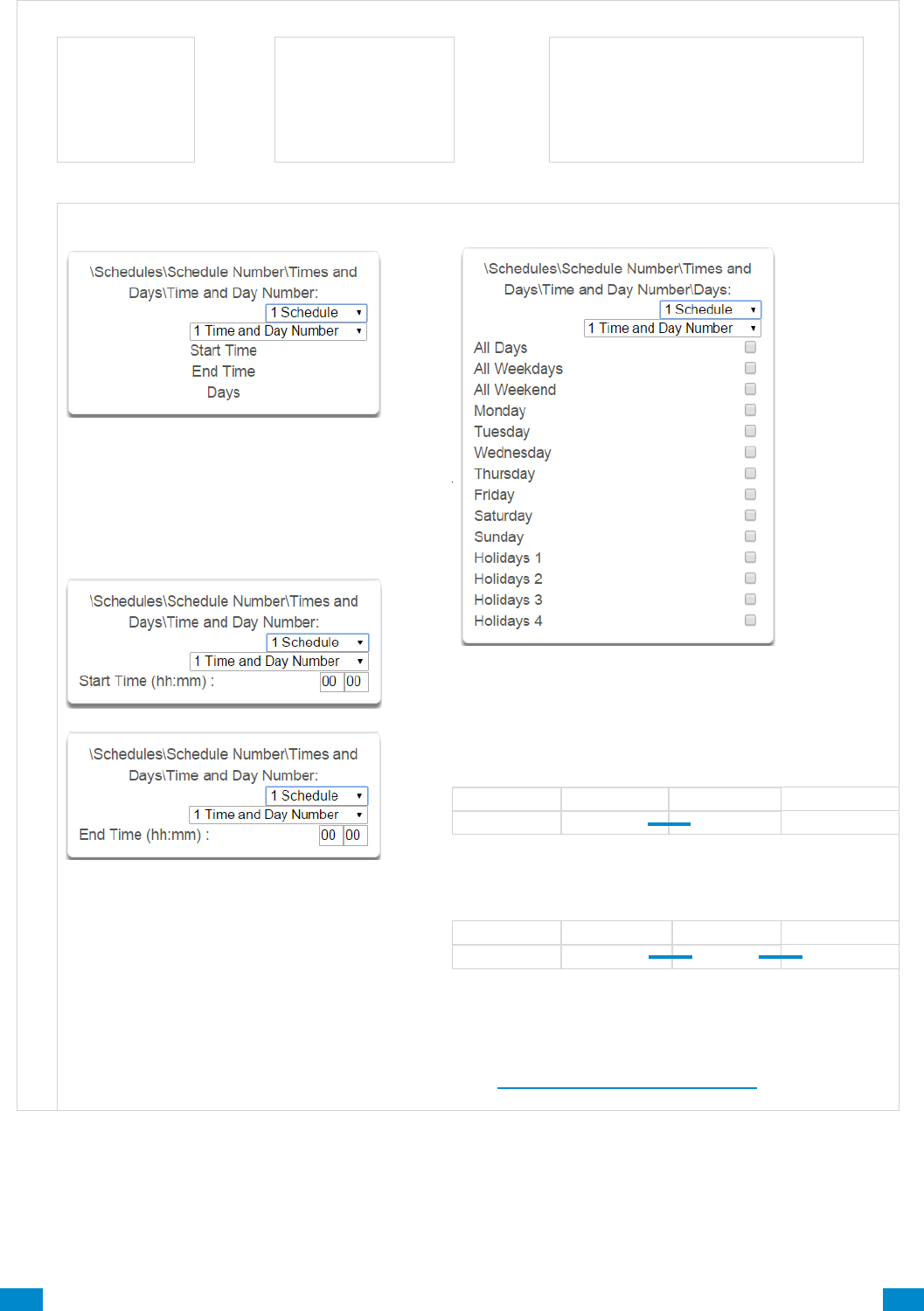
...C... 122 P/N 466-5261 • REV D ISS 17NOV17 UltraSync Modular Hub Reference Manual ©2016 United Technologies Corporation .... .I.....
S c h e d u l e s S u b m e n u s
Follow Action
Action
controls
Schedule
controls
Permissions
(users and devices)
Area Types
Sensor Profiles
Arm-Disarm
Scenes
4 Times and Days
Up to 16 sets of time and days can be
specified here.
6 Days / Holidays
The system handles schedules that span midnight
automatically. For example, if a schedule is to cover
Fri 8:00pm to Sat 6:00am, only check Friday and the
system will automatically manage the time after
midnight.
5 Start Time / End Time
Thu
Fri
Sat
Sun
If you check Friday and Saturday, the schedule will
cover Fri 8:00pm – Sat 6:00am and Sat 8:00pm –
Sun 6:00am.
Thu
Fri
Sat
Sun
Note: Holidays 1-4: If checked, it means the item
assigned this schedule will NOT have access during
the specified holiday dates.
See Advanced Programming,Holidays to program
these dates.

...C... 123 P/N 466-5261 • REV D ISS 17NOV17 UltraSync Modular Hub Reference Manual ©2016 United Technologies Corporation .... .I.....
6.7 Advanced Programming, Actions
The system features powerful automation control which can interact with different parts of the
system. It can perform functions based on the status of one or more system conditions.
These features are considered advanced programming and should only be changed by an
installer with a thorough understanding of the features.
Each action has an on and off state. The state is controlled by up to 4 conditions called Action
Events, each of which can have a range of items:
When all 4 Action Events are met, then the Action State (trigger) will be set. The Action State
can be monitored by the system, Schedules, Devices with outputs, and Scenes to
activate/deactivate.
For example, a strobe connected to Output 2 can be programmed to follow Areas 1 – 8 being
armed.
Each Action can also directly control selected parts of your system when all 4 Action Events
are met. This is called the Action Result. Its behavior also follows the Action State.
For example, when all areas are armed and there is activity on Sensor 1, activate a camera
recording.
Click the Advanced bar and select Actions from the menu to program actions options.
A c t i o n E v e n t S e q u e n c e
Event 1
and
Event 2
and
Event 3
and
Event 4
=
Action
State
(trigger)
+
Action
Result
or
or
or
S t r o b e A c t i o n S e q u e n c e
Areas 1 – 8 All Armed
=
Action 1 True
+
Activate Strobe
C a m e r a A c t i o n S e q u e n c e
Areas 1 – 8 Armed
and
Sensor 1 Faulted
=
Action 1 True
+
Activate Camera
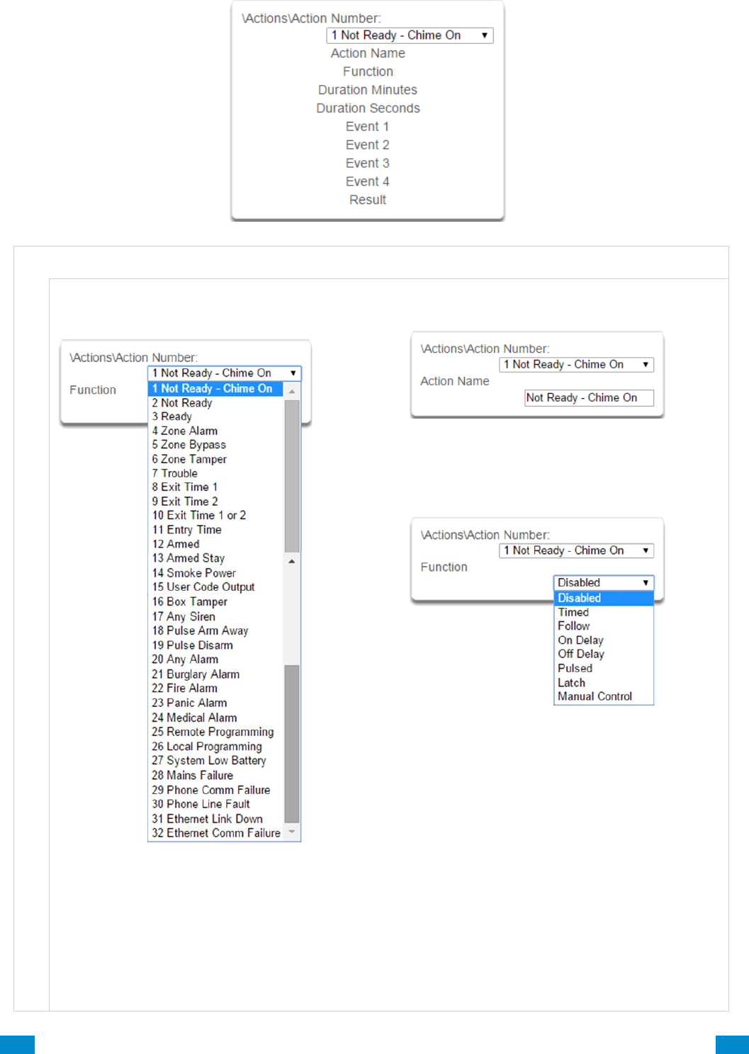
...C... 124 P/N 466-5261 • REV D ISS 17NOV17 UltraSync Modular Hub Reference Manual ©2016 United Technologies Corporation .... .I.....
A c t i o n s S u b m e n u s
A c t i o n s S u b m e n u s
1 Action Number
The system can support a total of 256 Actions. Each
Action is identified by a unique number, which cannot
be altered, and remains as the key reference for each
Action.
Note: All actions are pre-programmed with the
specified trigger. To create a new action, you need to
modify one of these actions.
2 Action Name
Each Action can be configured with a custom 32
character name. The name is displayed wherever
an Action is referenced on the system.
3 Function
Timed – The action state turns on for the time
specified.
Follow (Recommended) – The action state
turns on once the Event conditions have
been satisfied, then off once the Event
conditions are not true.
On Delay – The action state becomes on
after the programmed time period unless the
logic result is no longer active.
Off Delay – Follows the result of the logic
equation, but remains active for the time
programmed after the logic result is no longer
active.
On Pulse – Action state turns on for the
programmed time or the active period of the
logic result, whichever is the SHORTEST.
Latch – The action state stays on once the
Event conditions have been satisfied.
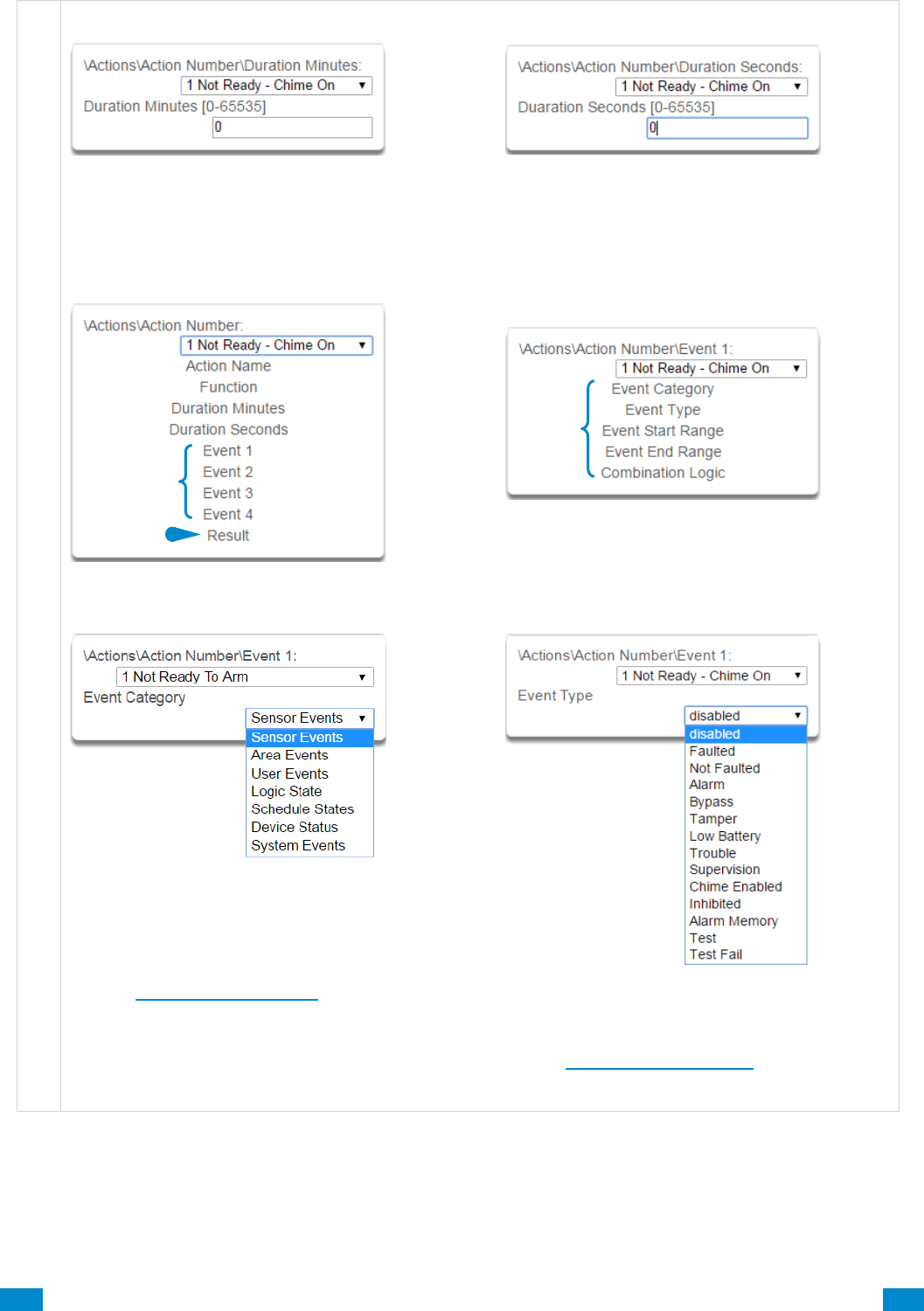
...C... 125 P/N 466-5261 • REV D ISS 17NOV17 UltraSync Modular Hub Reference Manual ©2016 United Technologies Corporation .... .I.....
A c t i o n s S u b m e n u s
4 Duration: Minutes
Where the Function requires duration, this
determines, in minutes, how long the action should
stay on.
5 Duration: Seconds
Where the Function requires duration, this
determines, in seconds, how long the action
should stay on.
6 Event(s) 1-4 and Results
7 Event Attributes
8 Event Category
Select the category of the first event. This will
determine what events you can select in Event
Type.
See the Action Events Category and Action Event
Types table in Section A.10 for reference.
9 Event Type
Select the event that you want the Action to
monitor.
See the Action Events Category and Action
Event Types table in Section A.10 for reference.
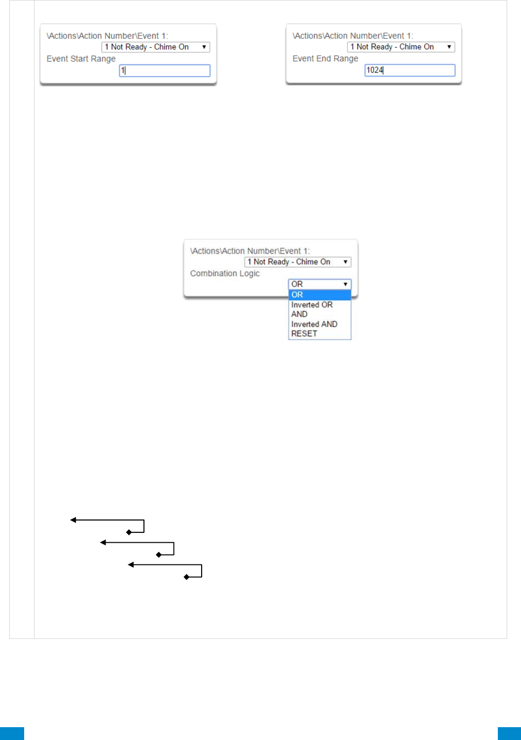
...C... 126 P/N 466-5261 • REV D ISS 17NOV17 UltraSync Modular Hub Reference Manual ©2016 United Technologies Corporation .... .I.....
A c t i o n s S u b m e n u s
10 Event Start Range
Select the starting number of the event that you want
the Action to monitor. This is related to a number
range. For example this might be the first area or
sensor number.
11 Event End Range
Select the ending number of the event that you
want the Action to monitor. This is related to a
number range. For example this might be the last
area or sensor number.
If you just want to monitor one item, then leave it
at the default of zero, or enter the same number
as Event Start Range.
12 Event Combination Logic
The logic condition to apply to Event 1
• OR e.g. Area 1 Armed Away OR Area 2 Armed Away
• Inverted OR e.g. NOT Sensor 1 Bypass OR Sensor 2 Bypass
• AND e.g. Area 1 Armed Away AND Area 2 Armed Away
• Inverted AND e.g. NOT Sensor 1 Bypass AND Sensor 2 Bypass
• RESET Reset any latched event
The Combination Logic selected for each event places the logic prior to the event in an equation.
Selecting the AND logic closes a parenthesis for the previous event. The DLX 900 software displays an
Event Equation field to make it easier to construct Actions.
For example:
Event 1 Inverted OR,
Event 2 OR,
Event 3 AND,
Event 4 OR
produces a logic equation of:
(NOT Event 1 OR Event 2) AND (Event 3 OR Event 4)
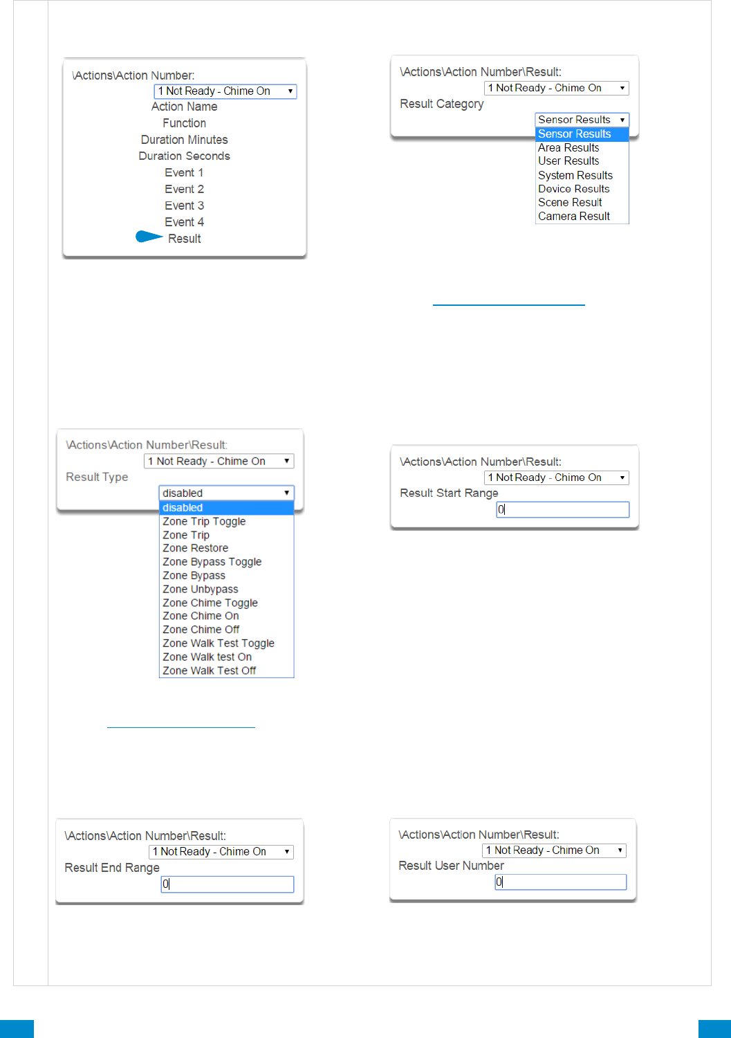
...C... 127 P/N 466-5261 • REV D ISS 17NOV17 UltraSync Modular Hub Reference Manual ©2016 United Technologies Corporation .... .I.....
A c t i o n s S u b m e n u s
13 Result
The system can also perform an additional function
once the Action Event conditions are satisfied. This
is called an Action Result.
For example, when a fire alarm is active, you could
disable Users 1-50 to prevent them from being able
to control the alarm system.
14 Result Category
Result Category: The category of the Action Result
to perform.
See the Action Results Category and Action
Results Event Types table in Section A.11
for reference.
15 Result Type
The event of the Action Result to perform
See the Action Results Category and Action
Results Event Types table in Section A.11
for reference.
16 Result Start Range
Select the starting number of the event that you
want the Action Result to affect.
17 Result End Range
Select the ending number of the event that you
want the Action Result to affect.
18 Result User Number
Select the User that you want the Action Result to
behave as. This will apply this user’s full
permissions to the Action Result you select.
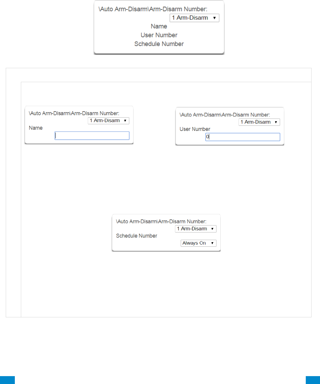
...C... 128 P/N 466-5261 • REV D ISS 17NOV17 UltraSync Modular Hub Reference Manual ©2016 United Technologies Corporation .... .I.....
6.8 Advanced Programming, Auto Arm-Disarm
Advanced Arm-Disarm programming allows the system to automate arming and disarming
according to a specified schedule.
Click the Advanced bar and select Arm-Disarm from the menu to program arm-disarm options.
A r m - D i s a r m S u b m e n u s
A r m - D i s a r m S u b m e n u s
1 Name
Each scenario can be configured with a custom 32
character name. The name is displayed wherever an
Arm-Disarm scenario is referenced on the system.
2 User Number
The user number that will perform the Arm-
Disarm. The user’s schedule and permissions will
be checked and applied to all areas in the user’s
arm or disarm area group at the time of the Arm-
Disarm.
3 Schedule Number
The system can support a total of 32 automated Arm-Disarm scenarios. Each scenario is identified by a
unique number, which cannot be altered, and remains as the key reference for each function.
The schedule number specified here determines when the arm and disarm is performed by the user
number. The starting date/time of the schedule will perform a disarm, the ending date/time of the
schedule will arm
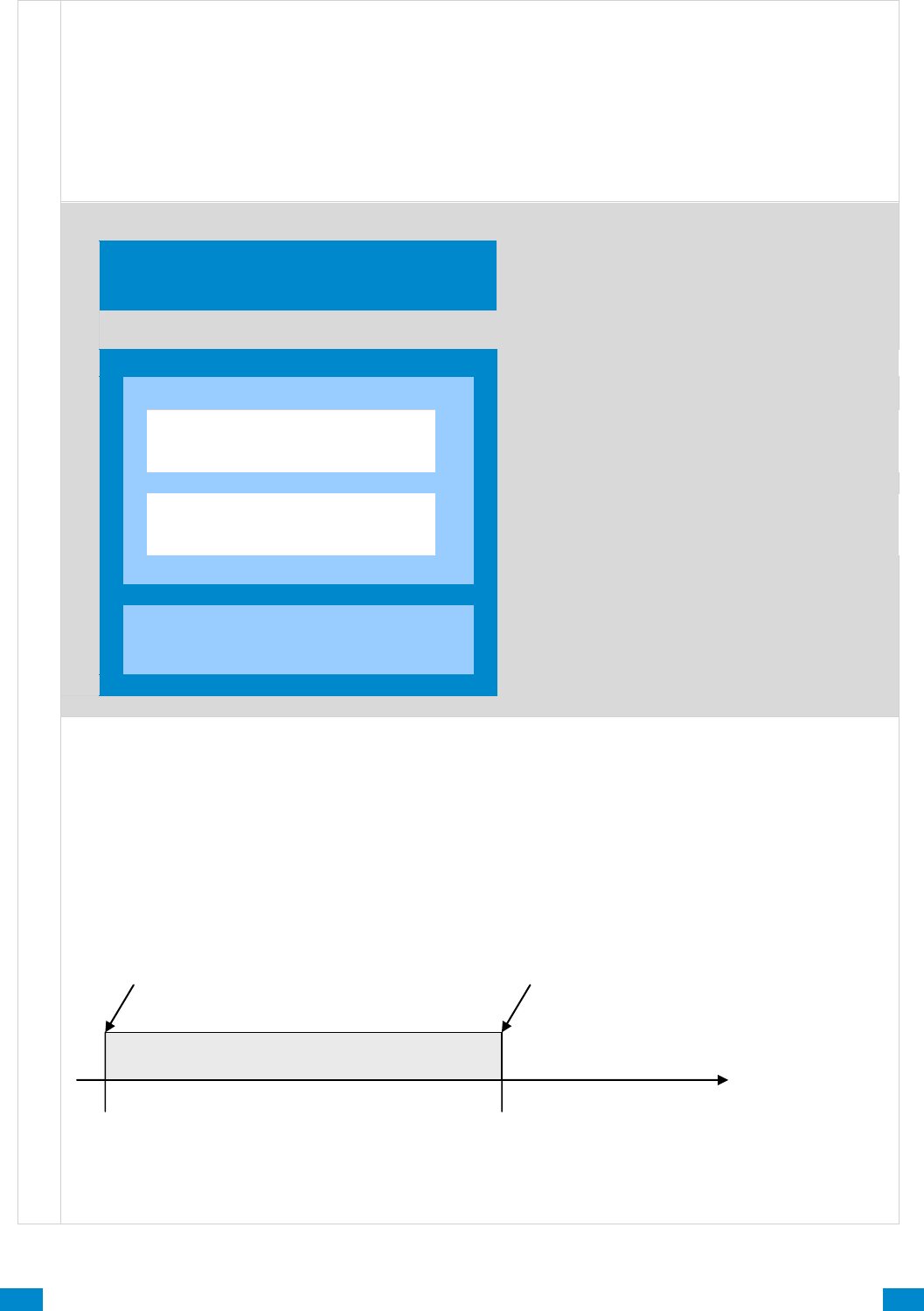
...C... 129 P/N 466-5261 • REV D ISS 17NOV17 UltraSync Modular Hub Reference Manual ©2016 United Technologies Corporation .... .I.....
A r m - D i s a r m S u b m e n u s
When a Schedule becomes valid (inside valid time sensor) the system will disarm all Areas that are in the
User’s - Active Profile - Disarm Area Group. When the Schedule becomes invalid (out of time sensor)
then the system will arm all areas that are in the User’s - Active Profile - Arm Area Group.
For example if we had Schedule 4 Mon-Fri 9am-5pm, and User 55 with permission to arm and disarm
area 1, 2, and 3, plus their schedule was 24 hours 7 days a week.
Then each weekday at 9am the system would disarm areas 1, 2, and 3 as if it were user 55. At 5pm each
weekday the system would arm areas 1, 2, and 3 as if it were user 55.
Arm Disarm Number 1 – Arm-Disarm Example
Schedule 4 – Office Hours
Mon – Fri
9am – 5pm
See Schedule to program
User 55 – Arm-Disarm User
See Users to program
Permission 99 – Full Access
Arm Area Group 1
1, 2, 3
See Permissions to program
Disarm Area Group 1
1, 2, 3
Schedule 1 – Full Access
7 days, 24 hours
See Schedule to program
For an Arm-Disarm to occur, both the Arm-Disarm schedule here and the User Schedule need to be valid
at the time the Arm-Disarm is triggered.
The Arm-Disarm Schedule determines what the operation is. The leading edge causes a disarming
function and trailing edge causes an arming function. The Users Permissions then determines which
areas if any are armed or disarmed. If the function is to disarm, the Users Disarm Area Groups will be
disarmed. If the function is to arm, the Users Arm Area Group will be armed.
More complex interactions with the system are possible by modifying the schedule selected here, the
schedule assigned to the user, and even combining actions to control schedules. Also, user permissions
can have up to 4 permission and schedule pairs.
Arm-Disarm Schedule 9am-5pm
9am
5pm
When the time becomes 9am, the Arm-
Disarm tries to disarm all areas using User
55 and their permissions, this includes
checking User 55’s schedule.
When the time becomes 5pm, the Arm-Disarm
tries to arm all areas using User 55 and their
permissions, this includes checking User 55’s
schedule .
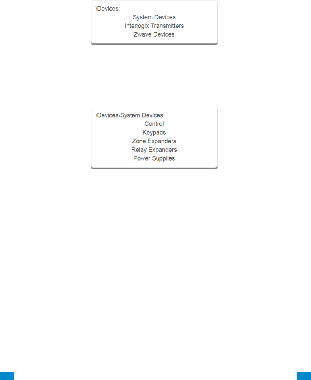
...C... 130 P/N 466-5261 • REV D ISS 17NOV17 UltraSync Modular Hub Reference Manual ©2016 United Technologies Corporation .... .I.....
6.9 Advanced Programming, Devices and Enrollment
Click the Advanced bar and select Devices from the menu to program device options.
This menu allows you to program devices connected to the system.
6.9.1 System Devices
Select System Devices to program and enroll devices including CPU (Control), keypads,
zone expansion modules, relay expansion modules and smart power supplies.
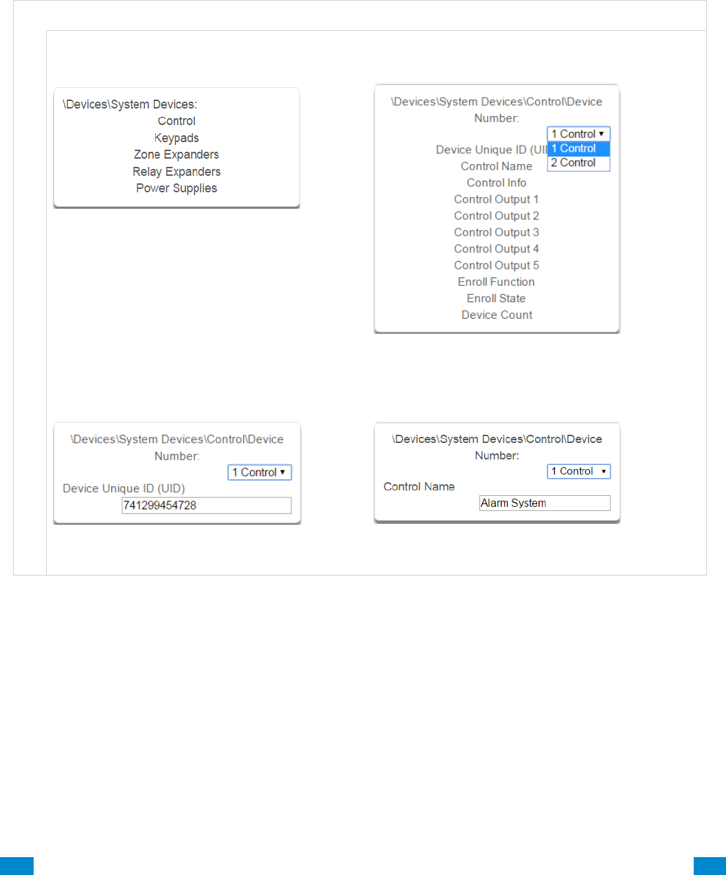
...C... 131 P/N 466-5261 • REV D ISS 17NOV17 UltraSync Modular Hub Reference Manual ©2016 United Technologies Corporation .... .I.....
6.9.1.1 Control Devices
Control Devices are currently limited to the CPU. Use this section to view the CPU serial
number, configure the name and view device information such as firmware and hardware
revisions. You can also program the 5 on-board CPU outputs, perform enrollment functions
and view the current system device counts.
D e v i c e s S u b m e n u s
D e v i c e s , C o n t r o l
1 System Devices Control
Select Control.
2 System Devices Control Device Number
Select among control devices to program them.
3 Device UID
Serial number of the CPU.
4 Control Name
The name of the system.
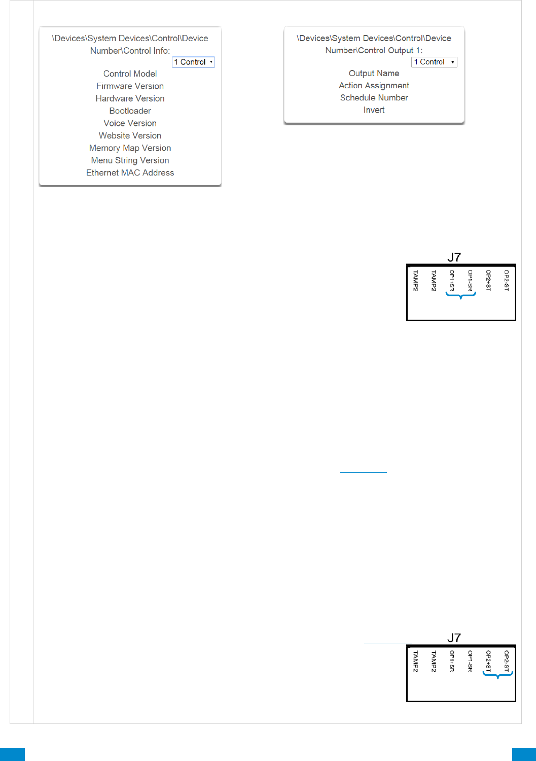
...C... 132 P/N 466-5261 • REV D ISS 17NOV17 UltraSync Modular Hub Reference Manual ©2016 United Technologies Corporation .... .I.....
D e v i c e s , C o n t r o l
5 Control Info
Version information about the system including
firmware, voice, web, and MAC address.
6 Control Output 1
The system has 5 on-board control outputs. While
some are defaulted to drive specific outputs, all of
them are programmable via actions. See the
following section detailing each control output.
6.9.1.1.1 Control Outputs
Control Output 1 – on terminal J7
Three modes of operation:
1. Defaulted as a siren driver that follows an alarm (DC output).
1a) Terminal OP1+SR supplies 13.8 VDC.
1b)Terminal OP1-SR provides ground when activated (via alarm or action).
1c) This is an open circuit when not activated
2. Configurable for speaker driver that follows alarm (sinusoidal output).
2a) Advanced\System\Siren Options: “Voltage Siren Output”
Off = speaker
On = DC siren
3. Configurable as programmable output via actions.
This line is supervised only if set up as a speaker or DC siren output.
Supervison does not require an EOL resistor when a speaker is connected.
Line is not supervised if configured as output via Actions.
An external tamper input (Tamp2) is available on the terminal strip to support an external enclosure.
To enable this opion, go to:
Advanced – System – Siren Options – Siren Box Tamper (View page)
Speakers: 15 or 30 watts
Speaker current draw for allowed Ohm rating, typical:
4Ω – 490 mA (max load, do not exceed this current draw)
8Ω – 230 mA “
16Ω – 138 mA “
Note: Current draw must be accounted for in your power budget calculations.
Control Output 2 – on terminal J7
Two modes of operation:
1. Default operates as a Strobe driver that follows alarm (DC output only).
Timing configured in Advanced – System Timers – Strobe Time (View Page)
2. Configurable as programmable output via actions.
Terminal OP2+ST supplies 13.8 VDC.
Terminal OP2-ST provides ground when activated (via alarm or action).
This is an open circuit when not activated.
Note: Current draw must be accounted for in your power budget calculations.
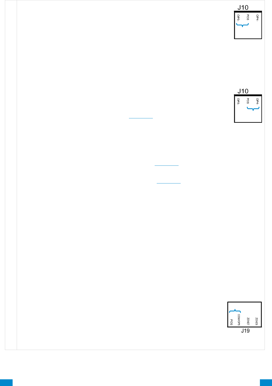
...C... 133 P/N 466-5261 • REV D ISS 17NOV17 UltraSync Modular Hub Reference Manual ©2016 United Technologies Corporation .... .I.....
D e v i c e s , C o n t r o l
Control Output 3 – on terminal J10
Two modes of operation:
1. Default operates as a Piezo driver that follows alarm (DC output only).
Configurable for DC Siren that follows alarm (DC output, same as Output 1).
No option for Speaker operation.
2. Configurable as programmable output via actions.
POS terminal on J10 supplying 13.8 VDC is shared with output 4.
OP3- provides ground when activated (via alarm or action).
Note: Current draw must be accounted for in your power budget calculations.
Control Output 4 – on terminal J10
Disabled by default.
Three modes of operation:
1. For 2-wire smoke detectors, mark the check box to enable in:
Advanced – System – General Options (View page)
Configure Sensor 8 Type as Fire Alarm
Configure Sensor 8 Sensor Options as Fire
Note: The system uses Zone 8 for two wire smoke. Zone 8 will be unavailable for use.
Limit of xx smoke detectors, future content
Note: Current draw must be accounted for in your power budget calculations.
2. For 4-wire smoke detectors, enable in:
Advanced – Devices – System Devices – Control (View page)
Select Control Output 4 to program
Select Action Assignment
Select Action 14, Smoke Power in drop down menu (View page)
Set output to invert
Wire detectors to any zone.
Configure Sensor Type as Fire Alarm
Configure Sensor Sensor Options as Fire
The number of smoke detectors is limited by the capacity of the system’s power supply. Multiple
outputs can be used to increase the detector capacity.
Note: Current draw must be accounted for in your power budget calculations.
3. Configurable as programmable output via actions.
POS terminal on J10 supplying 13.8 VDC is shared with output 3.
OP4- provides ground when activated (via alarm or action).
Note: Current draw must be accounted for in your power budget calculations.
Control Output 5 – on terminal J19
Disabled by default.
Programmable via Actions only.
Shared terminal with COM for zones 7 and 8.
If utilized for output Zone 7 and 8 must be wired to separate COM terminal.
POS terminal on J19 supplyies 13.8 VDC.
Note: Current draw must be accounted for in your power budget calculations.
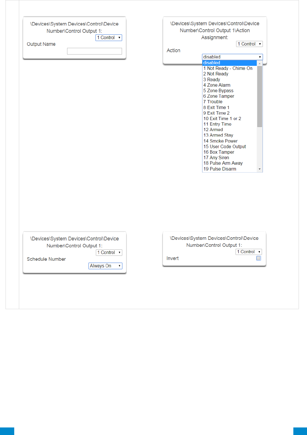
...C... 134 P/N 466-5261 • REV D ISS 17NOV17 UltraSync Modular Hub Reference Manual ©2016 United Technologies Corporation .... .I.....
D e v i c e s , C o n t r o l Devices, Control
7 Control Output, Output Name
Each output can be configured with a
custom 32 character name.
8 Control Output, Action Assignment
The output will activate while the selected action
state is true. If the action state becomes false then
the output will deactivate.
9 Control Output, Schedule Number
If a schedule is entered here then the output
will only be active when the schedule is valid.
If no schedule is entered then the output will
always function.
10 Control Output, Invert
Invert the Output (normally not used)
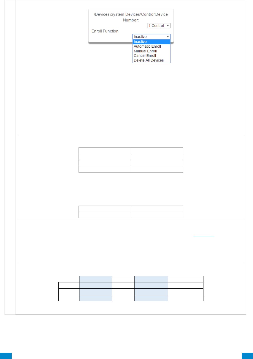
...C... 135 P/N 466-5261 • REV D ISS 17NOV17 UltraSync Modular Hub Reference Manual ©2016 United Technologies Corporation .... .I.....
D e v i c e s , C o n t r o l
6.9.1.1.2 Enrollment
11 Enroll Function
This menu allows you to add new devices to the system.
Inactive means no enrollment is active on the system.
Automatic Enroll (Automatic enrollment can also be initiated by pressing the Enroll button on the CPU)
This is recommended in two scenarios: Either 1) when you are first setting up your system or 2) when
enrolling one device only. The procedure automatically searches the bus for new connected devices and
adds them to the system in this way:
1st: By first open (available) slot or “position”.
This becomes the device number.
2nd: In order of Unit ID.
Example: Add 3 zone expansion modules to a new system.
Open slot #
Unit ID #
1
0101 1234
2
0101 1235
3
0102 1234
Unit ID numbers are in numerical order in the first open slots 1-3.
Later add 1 more module to your system. The next available slot is (4). Notice that the device in slot 4 has a
lower serial number than those in slots 1-3. But it is in order by available slot, which is prioritized over Unit ID.
Open slot #
Unit ID #
4
0100 1234
Alternatively, you may automatically enroll connected devices by holding down the S1 button on the main
panel for 3 seconds. The S1 LED (D5) will blink slowly to indicate automatic enrollment is in progress.
Confirmation messages also appear on the keypad. When the LED stops flashing then the enrollment
function has finished.
The system also assigns each device its correct device type. Example system with multiple devices:
Control Devices
Keypads
Zone Expanders
Relay Expanders
Device #
1
1
1
1
Device #
2
2
2
Device #
3

...C... 136 P/N 466-5261 • REV D ISS 17NOV17 UltraSync Modular Hub Reference Manual ©2016 United Technologies Corporation .... .I.....
D e v i c e s , C o n t r o l
Manual Enrollment
Option 1: Select Manual Enroll from the drop down menu. Then click Save. This puts system into
manual enrollment mode and waits for you to push the ENROLL button on the Expansion Module/device
you want to enroll. The benefit of manual enrollment is that you can control the sequence and device
numbering during enrollment. Simply push the Enroll button on the device to be enrolled after the Manual
Enroll mode has been enabled on the CPU.
Option 2:
This option requires the user manually enter the device Unit ID into the server. Go to:
Advanced – Devices – System Devices (View page)
Select the type of device you are enrolling: (Keypad – Zone Expander – Relay Expander)
Select the next available device number.
Click device UID.
Enter the device Unit ID in the form field and click Save.
The device is now enrolled in the system.
Note: You have 5 minutes to manually enroll devices before the system exits back into normal mode.
When the manual enrollment function is running, the bus will be disabled and no feature that requires
access to the main panel will work. This includes arming or disarming of areas.
Note: You can change the device number using the management software, DLX 900
Cancel Enroll will stop the manual enrollment mode when you click Save.
Replacing Devices
In the event of a physical device failure, a new device can be added to the system without the need to
enroll and reprogram the device settings.
To replace a system device go to:
Advanced – Devices – System Devices
Select the type of device you are deleting: (Keypad – Zone Expander – Relay Expander)
Select the device number of the device you are replacing.
Click Device Unique ID (UID).
Enter the new device’s UID that is printed on the product label into the form field and click Save.
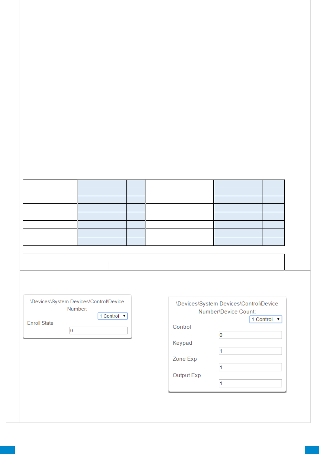
...C... 137 P/N 466-5261 • REV D ISS 17NOV17 UltraSync Modular Hub Reference Manual ©2016 United Technologies Corporation .... .I.....
D e v i c e s , C o n t r o l
Deleting Devices
Delete All Devices removes all expansion modules/devices from the system bus when you click Save.
Manually Delete Individual Devices
To manually delete system devices go to:
Advanced – Devices – System Devices
Select the type of device you are deleting: (Keypad – Zone Expander – Relay Expander)
Select the device number of the device you are deleting.
Click Device Unique ID (UID).
Scenario 1
Clear the Device Unique ID (UID) from the form field, or enter “0” and click Save.
This causes all of the remaining devices to shift up in slot or “position” to fill the newly cleared slot.
Scenario 2
Clear the Device Unique ID (UID) from the form field, then enter “1” and click Save.
This holds that slot until the next auto enrollment. This becomes an available position.
Auto enrollment fills the first available position.
Scenario 3
Clear the Device Unique ID (UID) from the form field, then enter “2” and click Save.
This permanently holds that position until a new Unit ID is entered for this position, (filled manually only).
Auto enrollment does not fill this position; rather it fills the next open position at the end of the list.
Deletion example: Device 2 needs replacement and is being deleted, with three different scenarios.
Original Device List
Scenario 1
result
Scenario 2
result
Scenario 3
result
1
1
1
1
2
Clear field, type “0”
2
Clear field, type “1”
held*
Clear field, type “2”
held†
3
3
2
2
4
4
3
3
5
5
4
4
6
open
5
5
open
open
open
open††
* Slot held until the next auto enrollment. This becomes the first available position that auto enrollment fills.
† Slot held for manual enrollment only.
††Auto enrollment would fill this next open position at the end of the list.
12 Enroll State
Read only field, this is the current state of the CPU.
When accessing remotely for programming this
area reports back the state of the CPU.
0 = Inactive
1 = Auto Enrollment
2 = Manual Enrollment
13 Device Count
This displays the number of additional keypads,
zone expanders, and relay expanders currently
enrolled on the system.
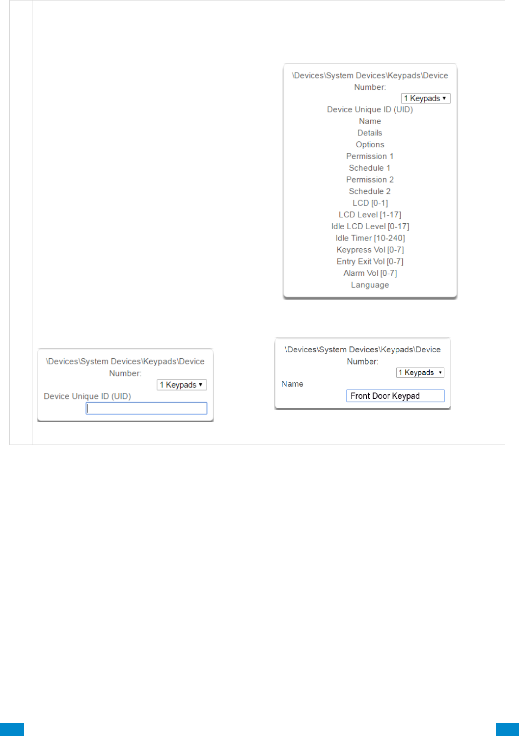
...C... 138 P/N 466-5261 • REV D ISS 17NOV17 UltraSync Modular Hub Reference Manual ©2016 United Technologies Corporation .... .I.....
D e v i c e s , K e y p a d s
6.9.1.2 Keypads
Keypad details as well as several selections for customizing the keypad operation are available in these
submenus.
14 Keypad
15 Device Unique ID (UID)
Unique ID number of the keypad.
16 Name
Name of the keypad.
Keypad enrollment using the automated
enrollment process is best achieved by
connecting one keypad at a time.
Use the manual process if multiple keypads
are connected.
It is recommended to enroll 1 keypad in the
system initially.
This allows you to retrieve the system’s IP
address (or set it if DHCP not enabled in the
router), which in turn allows access to the GUI
for manually enrolling additional devices.
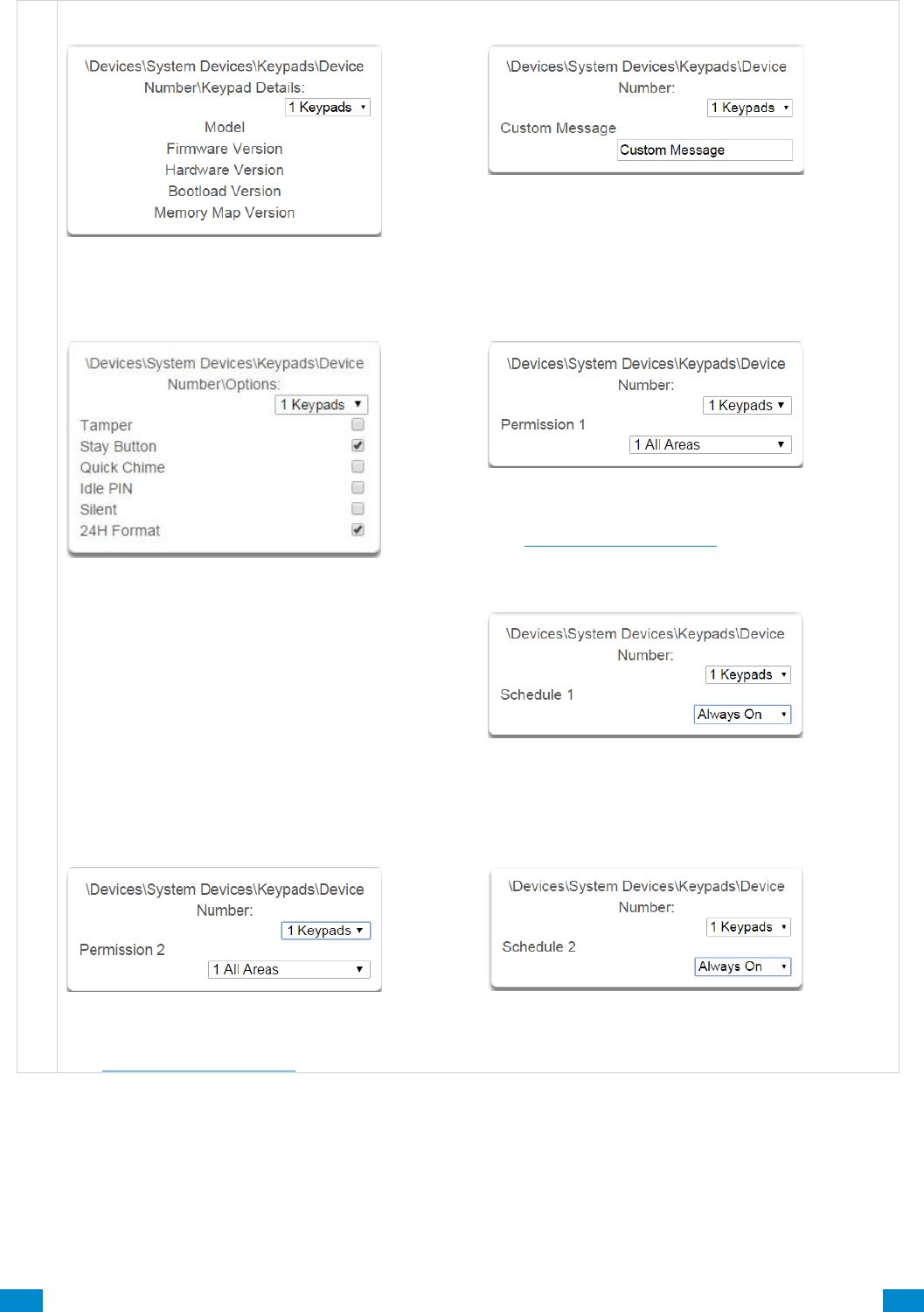
...C... 139 P/N 466-5261 • REV D ISS 17NOV17 UltraSync Modular Hub Reference Manual ©2016 United Technologies Corporation .... .I.....
D e v i c e s , K e y p a d Devices, Keypad
17 Keypad Details
Information about the keypad including firmware,
hardware versions, etc.
18 Custom Message
A custom message of up to 16 characters an be
entered here.
19 Keypad Options
Tamper: Enable the rear wall tamper switch on the
keypad.
Stay Button: Enable the Stay button to appear on
the main screen, when this is set to N (disabled) it
is also called “Commercial Mode”.
Quick Chime: Turn global chime on for partitions
the keypad and user have permission to access.
Idle PIN: Require a valid user PIN to be entered to
exit screen saver mode.
Silent Keypad: Disable keypad sounds.
24H Format: Display the time in 24:00 format.
20 Permission 1
Permission 1 is the first permission applied, and
checked against, when using the selected keypad.
See Section 7.3, Permissions for details.
21 Schedule 1
Schedule 1 refers to when Permission 1 is applied.
22 Permission 2
Permission 2 is the second permission applied, and
checked against, when using the selected keypad.
See Section 7.3, Permissions for details.
23 Schedule 2
Schedule 2 refers to when Permission 2 is applied.
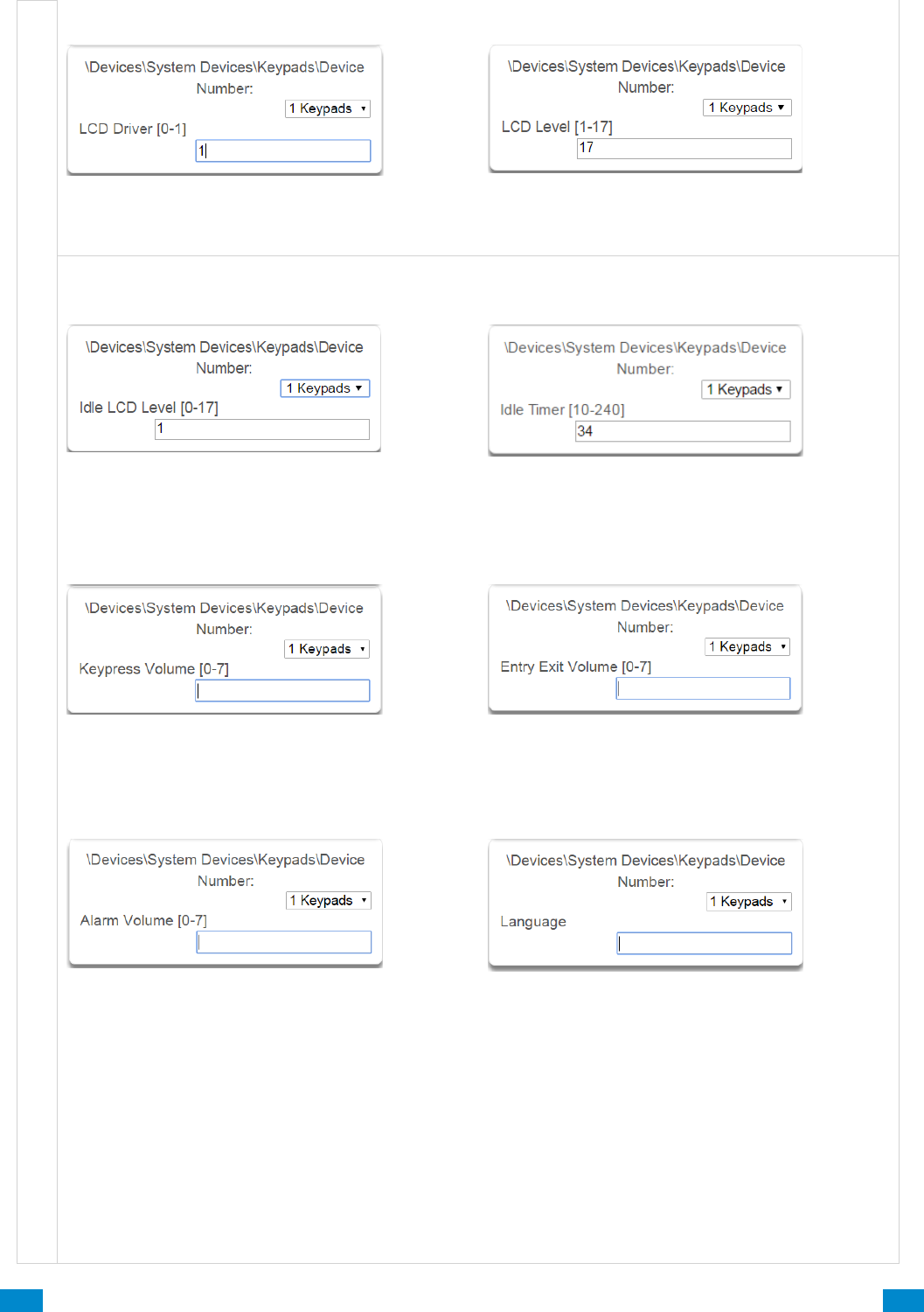
...C... 140 P/N 466-5261 • REV D ISS 17NOV17 UltraSync Modular Hub Reference Manual ©2016 United Technologies Corporation .... .I.....
24 LCD (0-1)
Sets the display mode of the keypad. Do not
change this value if the keypad display is working
correctly.
25 LCD Level (1-17)
Sets the normal brightness level of the keypad,
D e v i c e s , K e y p a d
26 Idle LCD level (0-17)
Sets the idle mode brightness of the keypad when it
has not been used. This reduces power
consumption and glare.
27 Idle Timer (10-240)
Sets the screen timeout when not used, and dims
the screen from LCD Level to Idle LCD Level.
28 Keypress Volume
Sets the beep volume when the keys are pressed.
29 Entry Exit Volume
Sets the volume of the warning beeps used during
entry and exit delays.
30 Alarm Volume
Sets the alarm volume.
31 Language
Enter the language code to set the default
language of the keypad interface. Only select
languages will be available depending on your
region. See below.
Language Code
Language
0
English (U.S.)
1
English (Australia)
2
English (U.K.)
3
German
4
Dutch
5
Dutch (Belgium)
Language Code
Language
6
French (Belgium)
7
French
8
Italian
9
Spanish
10
Portuguese
11
Greek
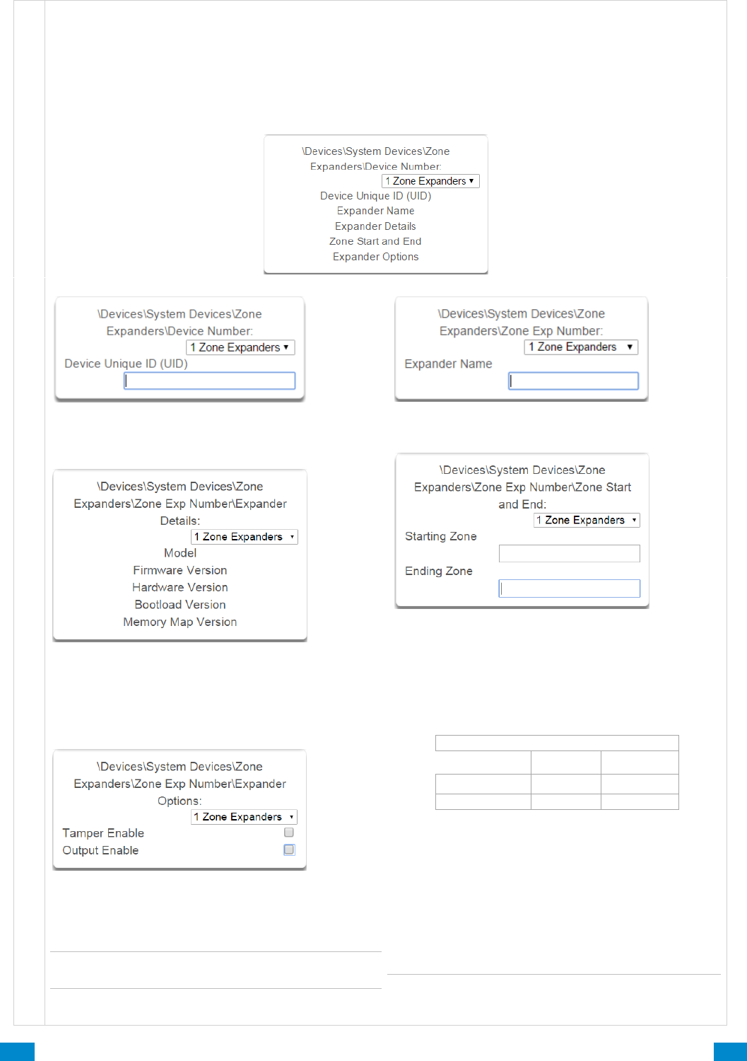
...C... 141 P/N 466-5261 • REV D ISS 17NOV17 UltraSync Modular Hub Reference Manual ©2016 United Technologies Corporation .... .I.....
D e v i c e s , Z o n e E x p a n s i o n M o d u l e s
6.9.1.3 Zone and Wireless Expansion Modules
Zone and wireless expansion modules must be enrolled into the system then programmed for proper
operation to be achieved. This section details the programming of these devices after they have been
enrolled. Note that it is only required to program the hardwired zones on the wireless expansion module if
you elect to utilize them. It is not required to program the start and end zone for the wireless sensors. Care
must be taken to not learn a wireless sensor into a zone that is programmed as a hardwired input.
Wireless sensors currently can be learned in as sensors 1-192
32 Zone Expanders
33 Device Unique ID (UID)
Unique ID of the zone expander.
34 Expander Name
Name of the zone expander.
35 Expander Details
Details of the expander module.
37 Expander Options
36 Zone Start and End
After enrolling a zone or wireless expansion
module, its zone range (Start Zone and End Zone)
must be programmed. Each module has its own
range. The start zone needs to account for CPU
zones and other existing modules. (The CPU can
be 8 to 16 zones depending on the implementation
of zone doubling).
If Output Enable is checked, the output operates as
the smoke detector reset on 4 wire smoke
detectors.
Note: If you are working with a Wireless Expander,
the Output Enable option is unavailable.
Not all of the zones of a module need to be used but
the zones must be used in order starting at #1 on
the module
For example: Use a 20 zone module to add 12
zones to an eight zone (CPU only) system.
Your Start Zone is # 9.
Your End Zone is # 20.
You must wire zones 1 – 12 on the expander.
There are now 8 unused zones available in the
system’s total count of available zones.
Note: The default start and end zones for the
wireless expander are 0 and 0. This disables the two
hardwired zones on the wireless expander.
Default Zone Expander Settings
8 Zone Exp.
20 Zone Exp.
Start Zone
9
9
End Zone
16
28
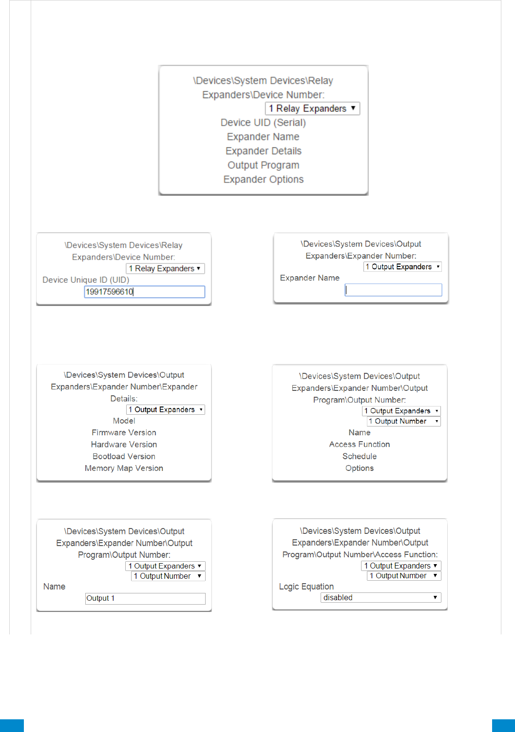
...C... 142 P/N 466-5261 • REV D ISS 17NOV17 UltraSync Modular Hub Reference Manual ©2016 United Technologies Corporation .... .I.....
D e v i c e s , O u t p u t E x p a n s i o n M o d u l e s
6.9.1.4 Relay Expansion Modules
Relay expansion modules must be enrolled into the system then programmed for proper operation to be
achieved. This section details the programming of these devices after they have been enrolled.
38 Relay Expanders
39 Device Unique ID (UID)
Unque ID (UID) of the relay expander.
40 Expander Name
Name / number of the relay expander.
41 Expander Details
42 Output Program
43 Output Program name
Name of the Output Program.
44 Access Function
Access cotrol is not supported at this time.
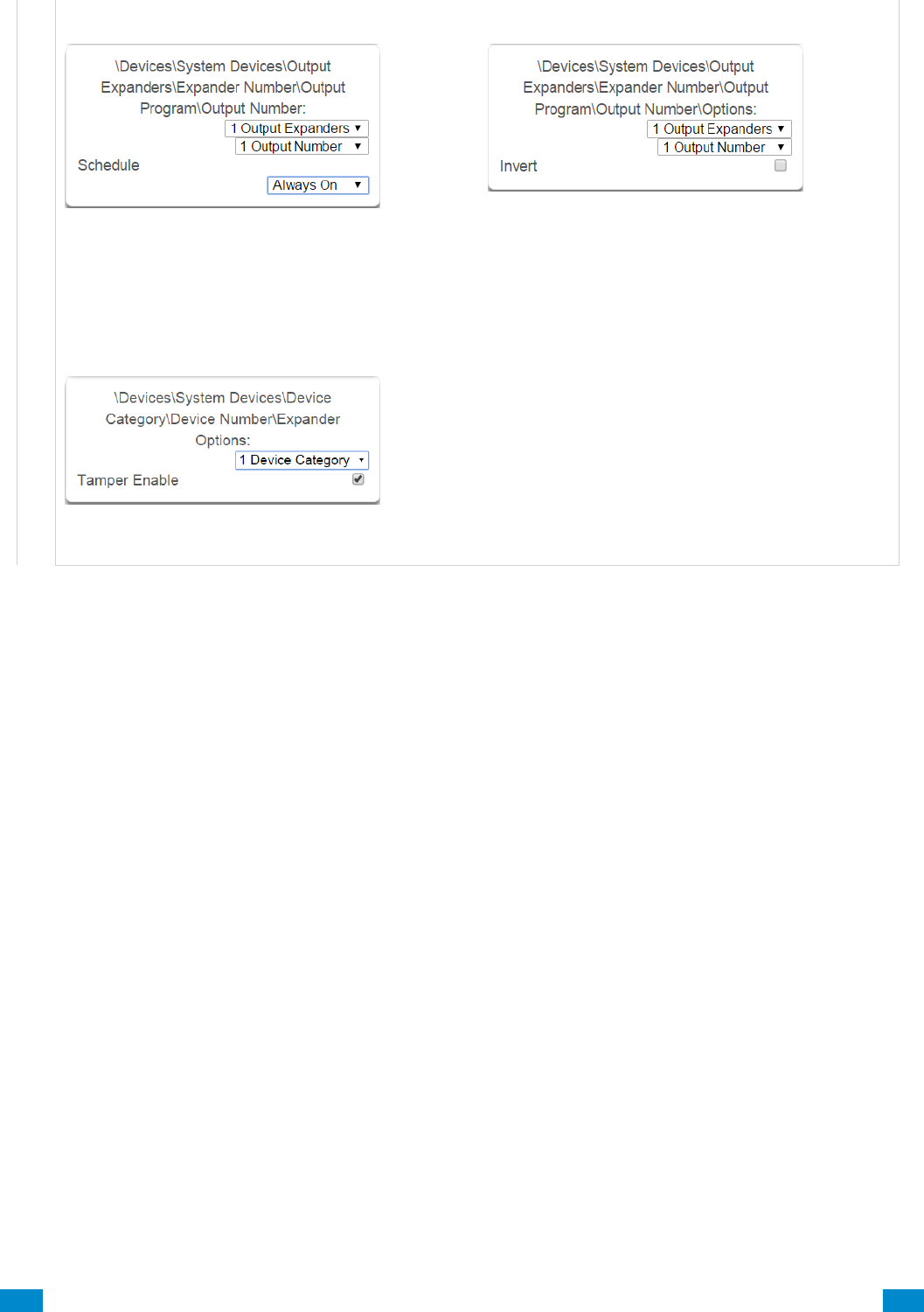
...C... 143 P/N 466-5261 • REV D ISS 17NOV17 UltraSync Modular Hub Reference Manual ©2016 United Technologies Corporation .... .I.....
45 Schedule
Sets when the output expander will be used.
46 Options
Invert option is the only option currently available.
The Default relay position is NC (normally closed).
If the “Invert” tick box is selected when configuring
the relay, then the relay will be in the NO (normally
open) position (and energized, consuming power).
47 Expander Options
This is the physical tamper button on the relay
housing.
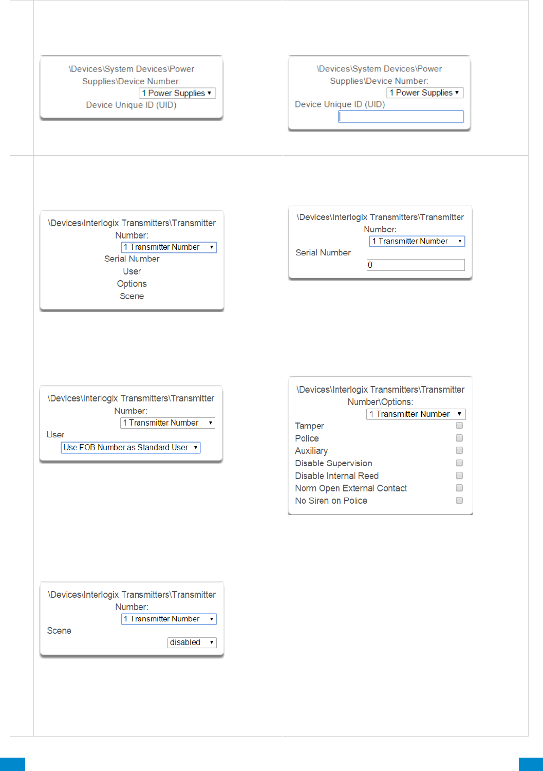
...C... 144 P/N 466-5261 • REV D ISS 17NOV17 UltraSync Modular Hub Reference Manual ©2016 United Technologies Corporation .... .I.....
P o w e r
6.9.1.5 Power Supplies
48 Device Number
Number of the Power Supply.
49 Serial Number
Unique ID (UID) of the Power Supply.
D e v i c e s , I n t e r l o g i x T r a n s m i t t e r s
6.9.2 Interlogix Transmitters
50 Interlogix Transmitters
Number of the Interlogix Transmitter.
This refers to all wireless sensors and keyfobs.
51 Serial Number
Serial number of the Interlogix Device
52 User
By default all keyfobs are reported as user 999. To
enable individual keyfob reporting, assign a user
number here.
54 Scene
On a four-button keyfob, this allows the user to
activate a scene when the fourth button is pressed
53 Transmitter Options
Allows the Installer to configure options for wireless
transmitters including:
• Tamper
• Police
• Auxiliary
• Disable Supervision
• Disable Internal Reed – this applies to
transmitters with an internal reed switch
• Norm Open External Contact
• No Siren on Police
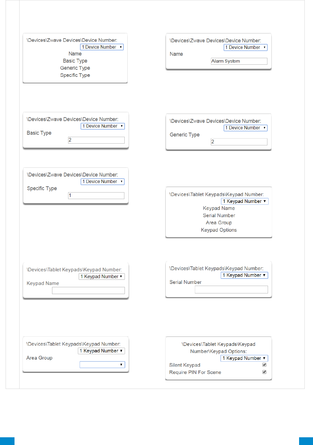
...C... 145 P/N 466-5261 • REV D ISS 17NOV17 UltraSync Modular Hub Reference Manual ©2016 United Technologies Corporation .... .I.....
D e v i c e s , Z - W a v e
6.9.3 Z-Wave Devices
55 Z-Wave Devices
56 Z-Wave Devices Name
57 Z-Wave Devices Basic Type
58 Z-Wave Devices Generic Type
59 Z-Wave Devices Specific Type
6.9.4 Tablet Keypads
63
61 Tablet Keypad Name
The name of the Tablet Keypad
62 Tablet Serial Number
The serial number of the Tablet Keypad
63 Area Group
The area the Tablet Keypad is assigned to.
64 Keypad Options
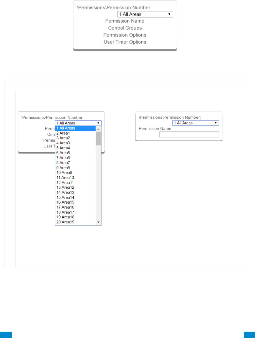
...C... 146 P/N 466-5261 • REV D ISS 17NOV17 UltraSync Modular Hub Reference Manual ©2016 United Technologies Corporation .... .I.....
6.10 Advanced Programming, Permissions
Click the Advanced bar and select Permissions from the menu to program permissions options.
Permissions control what a user or device has access to on the system and what they can do.
P e r m i s s i o n s S u b m e n u s
P e r m i s s i o n s S u b m e n u s
1 Permission Number
2 Permission Name
The system can support a total of 128 Permission
scenarios. Each scenario is identified by a unique
number, which cannot be altered, and remains as
the key reference for each Permission.
Each Permission scenario can be configured with a
custom 32 character name. The name is displayed
wherever Permissions are referenced on the
system.
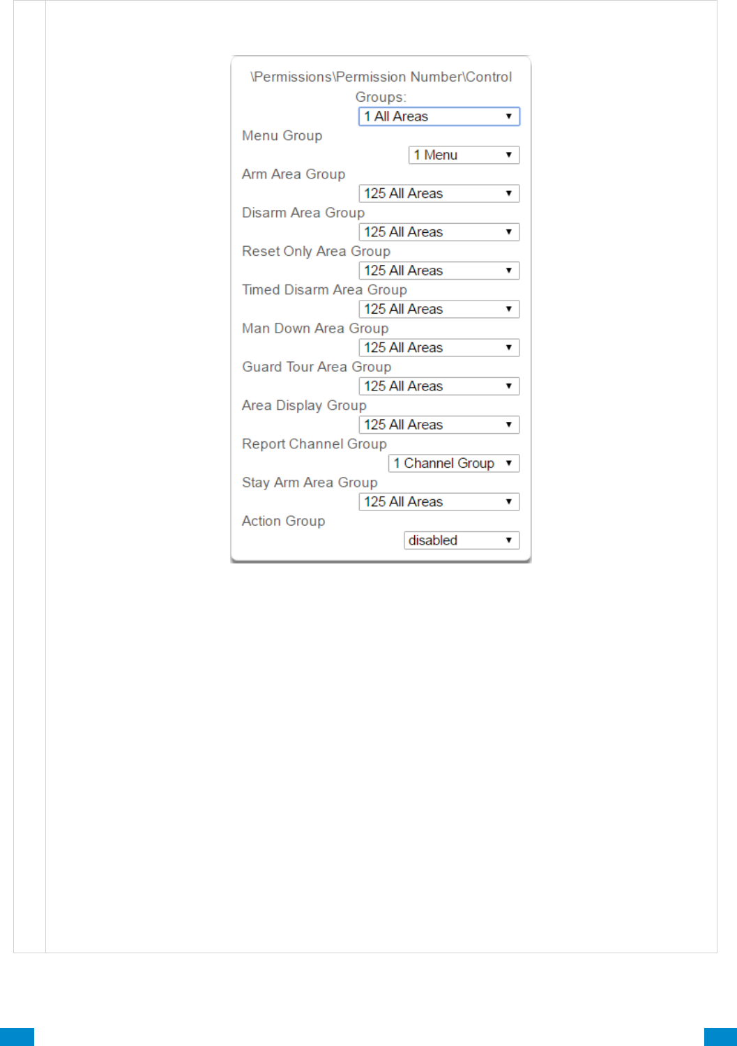
...C... 147 P/N 466-5261 • REV D ISS 17NOV17 UltraSync Modular Hub Reference Manual ©2016 United Technologies Corporation .... .I.....
P e r m i s s i o n s S u b m e n u s
3 Control Groups
1. Menu Group
This controls what menus the user or device can
access
2. Arm Area Group
This controls which areas can be armed.
3. Disarm Area Group
This controls which areas can be disarmed.
4. Reset Only Area Group
This controls which areas can be reset only.
For example, if a guard is present on the site you
may not want them to be able to disarm any areas.
By assigning them a Reset Only Area Group, they
can turn off alarms, but they cannot accidentally
disarm an area.
5. Timed Disarm Area Group
This controls which areas can be timed disarm.
6. Man Down Area Group
This controls which areas will have man down
monitoring.
7. Guard Tour Area Group
This controls which areas are a part of the guard
tour.
8. Area Display Group
This controls what areas can display area status.
9. Report Channel Group
This controls what channels the user can modify.
10. Stay Arm Area Group
This controls what areas can be stay armed.
11. Action Group
This controls what actions can be displayed or
accessed.
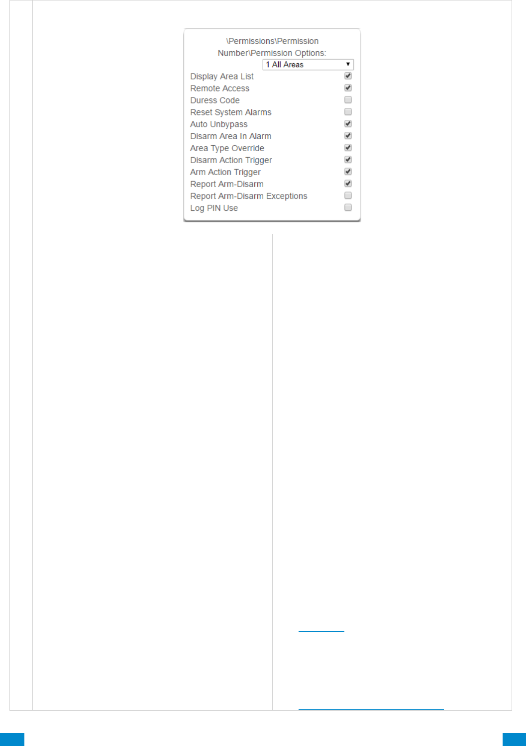
...C... 148 P/N 466-5261 • REV D ISS 17NOV17 UltraSync Modular Hub Reference Manual ©2016 United Technologies Corporation .... .I.....
P e r m i s s i o n s S u b m e n u s
4 Permission Options
1. Display Area List - When this feature is enabled
on a multi-area system and a user requests to
arm/disarm from the main screen of the keypad, the
keypad will display the area control screen that will
allow them to arm individual areas. If this feature is
disabled, the keypad will automatically arm/disarm
all areas. This operation applies to Custom user
types. You can enable or disable this feature for
non-Custom users in the Users Menu.
2. Remote Access - Enables and disables remote
web access to the permission. If this is not
enabled, a user will not be able to access the web
interface directly or via a smartphone app.
3. Duress Code - designates this user as a duress
code, whenever this code is used a duress
message is sent.
4. Reset System Alarms - when System Option -
System Alarm Latch is enabled, system alarms
include panel box tamper can only be reset by a
user with this permission. Users without this
permission will be able to arm and disarm areas as
normal, but system alarms will stay latched.
5. Auto Un-Bypass - When enabled, a bypassed
sensor will be reset when disarming. When
disabled, the Sensor will remain bypassed even
after the system has been disarmed.
6. Disarm Area In Alarm - When disabled, this
user will not be able to disarm and reset an area in
alarm. Even if the user has permission in their
Disarm Area Group, this option will override disarm
authority.
7. Area Type Override - Applies to non-standard
area types 'Time Disarm' 'Man Down' 'Guard Tour'.
When set, disables the feature for the user.
8. Disarm Action Trigger - When enabled, this
users will trigger the Action trigger event “User
Disarm Trigger” when disarming an area, used in
conjunction with for programming actions.
9. Arm Action Trigger - When enabled, this user will
trigger the Action trigger event “User Arm Trigger”
when arming an area, used in conjunction with for
programming actions.
10. Report Arm/Disarm - Where a system is
already configured to send Arm-Disarm reports this
option allows a user to NOT send a report. When
enabled the reports will be sent. When disabled
reports will not be sent.
11. Report Arm-Disarm Exceptions –
Report Arm-Disarm Exceptions = ON:
All four reports are sent as appropriate.
Early Opening
‘Fail To Open’ and the reset report ‘Late Open’
Early Close
‘Fail To Close’ and the reset report ‘Late Closing’
Report Arm-Disarm Exceptions = OFF:
As expected the only reports are the ‘Fail To Open’
and ‘Fail To Close’ reports with their respective
resets ‘Late Open’ and ‘Late Close’. Both the ‘Early
Open’ and ‘Early Close’ reports were suppressed.
‘Fail To Open’ and the reset report ‘Late Open’
‘Fail To Close’ and the reset report ‘Late Closing’
See Area Type for more details.
12. Log PIN Use - Log will show "Valid Code
Entered" when enabled. Must be enabled to allow
actions and scene events to monitor user
interaction. Also see how to set up having users
trigger scenes in the Activate Event Type List.
See Advanced Programming, Scenes.
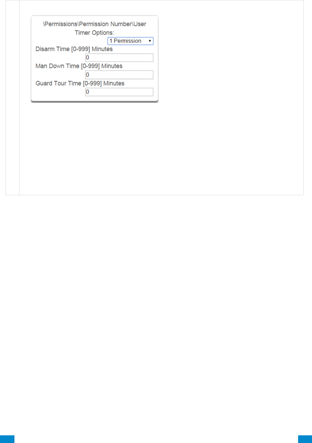
...C... 149 P/N 466-5261 • REV D ISS 17NOV17 UltraSync Modular Hub Reference Manual ©2016 United Technologies Corporation .... .I.....
P e r m i s s i o n s S u b m e n u s
5 User Timer Options
1. Disarm Time
2. Man Down Time
3. Guard Tour Time
These timers apply to a user when allocated this permission and:
• the Area Type is set to Timed Disarm, Man Down, or Guard Tour,
• is inside Area Type schedule,
• and Area Type Override is NOT enabled under Permission Options
If the value of the associated timer is zero, then the system will apply a timer of 45min.
See Area Type Settings for a more detailed description on these features.
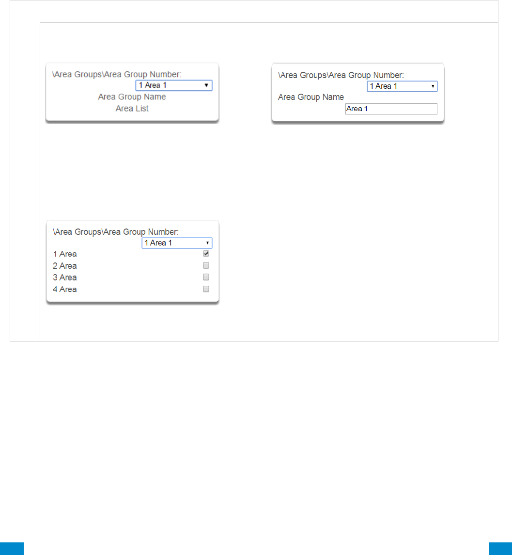
...C... 150 P/N 466-5261 • REV D ISS 17NOV17 UltraSync Modular Hub Reference Manual ©2016 United Technologies Corporation .... .I.....
6.11 Advanced Programming, Area Groups
Click the Advanced bar and select Area Groups from the menu to program area groups
options.
The system can support a total of 16 Area Groups. Each Area Group is identified by a
unique number, which cannot be altered, and remains as the key reference for each area.
When assigned to a user, an Area Group controls what areas the user can see and control.
When assigned to a sensor or device, an Area Group determines what Areas that
sensor/device will report and display in.
A r e a G r o u p s S u b m e n u s
A r e a G r o u p s S u b m e n u s
1 Area Group Number
The system can support a total of 128 Area
Groups. Each Area Group is identified by a
unique number, which cannot be altered, and
remains as the key reference for each area.
2 Area Group Name
Each group can be configured with a custom 32
character name. The name is displayed wherever
an Area Group is referenced on the system.
3 Area List
Select the areas that should be part of this Area
Group.
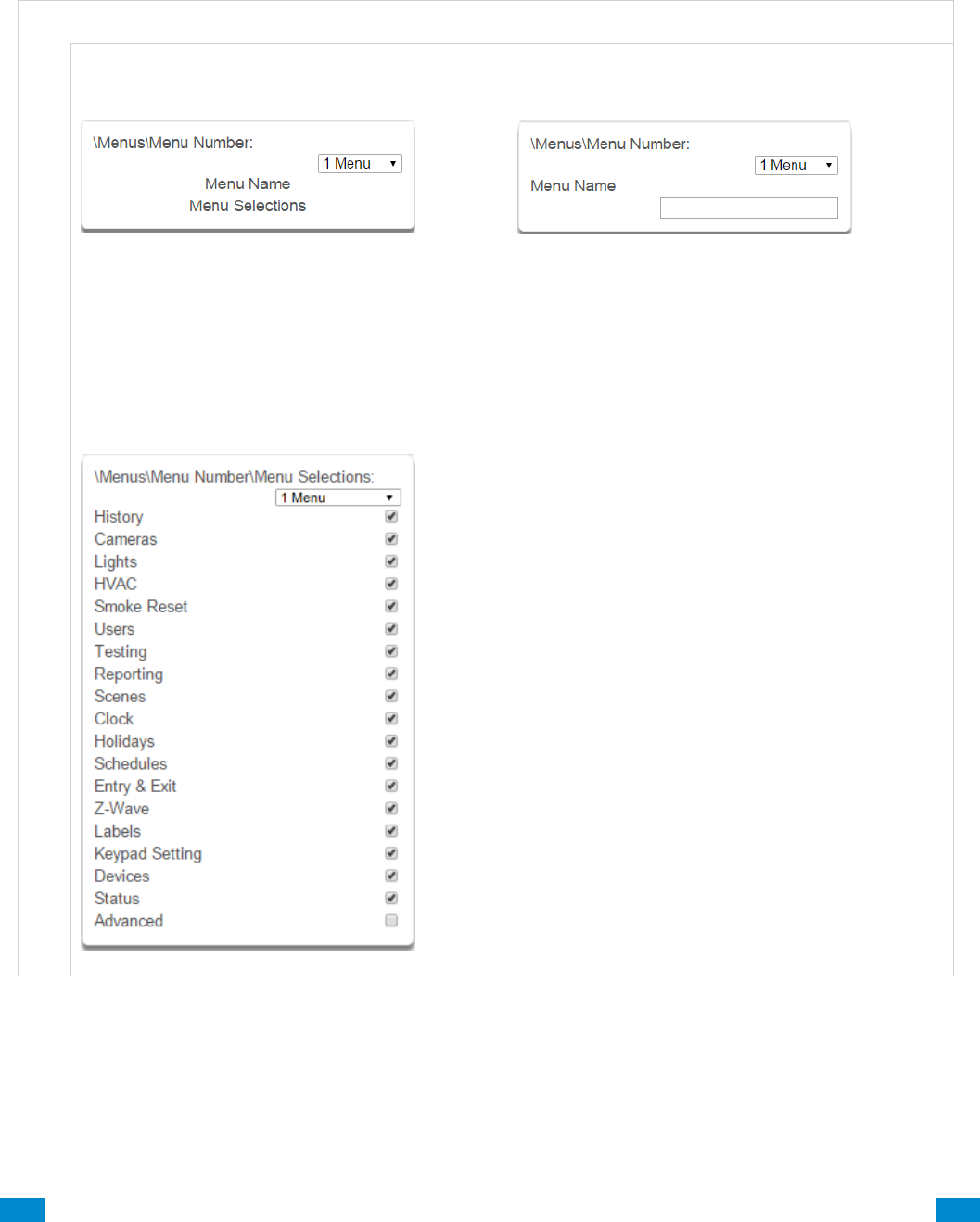
...C... 151 P/N 466-5261 • REV D ISS 17NOV17 UltraSync Modular Hub Reference Manual ©2016 United Technologies Corporation .... .I.....
6.12 Advanced Programming, Menus
Click the Advanced bar and select Menus from the menu to program menus options.
Menus are assigned to users and devices to control what menus can be accessed. A total of
64 Menus can be configured.
M e n u s S u b m e n u s
M e n u s S u b m e n u s
1 Menu Number (1 – 64)
The system can support a total of 64 Menu
Groups. Menu Groups are assigned to users and
devices to control what menus can be accessed.
Each Menu is identified by a unique number,
which cannot be altered, and remains as the key
reference for each Menu.
2 Menu Name
Each Menu can be configured with a custom 32
character name. The name is displayed wherever a
Menu is referenced on the system.
3 Menu Selections
Check each item to give a user access to that
menu. For example, checking Labels permits a
user with this Menu in their permission to change
the text labels (names) of sensors, areas, outputs,
etc.
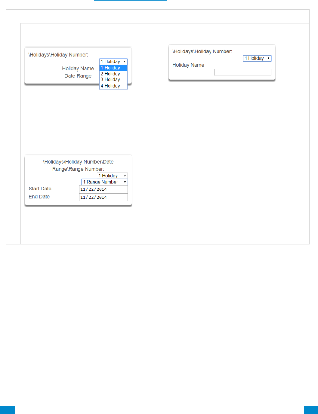
...C... 152 P/N 466-5261 • REV D ISS 17NOV17 UltraSync Modular Hub Reference Manual ©2016 United Technologies Corporation .... .I.....
6.13 Advanced Programming, Holidays
Click the Advanced bar and select Holidays from the menu to program holidays options.
Also reference Section 5.9, Programming Holidays
H o l i d a y s S u b m e n u s
H o l i d a y s S u b m e n u s
1 Holiday Number (1 – 4)
The system can support a total of 4 Holiday Sets.
Each set can have up to 16 date ranges. Holidays
are used as part of Schedules to control access to
the system on specified dates.
2 Holiday Name
Each holiday can be configured with a custom 32
character name. The name is displayed wherever a
Holiday is referenced on the system.
3 Holiday Date Range
Select the date range for the Holiday by specifying
the start and stop date. A total of 16 ranges can be
entered for each Holiday.
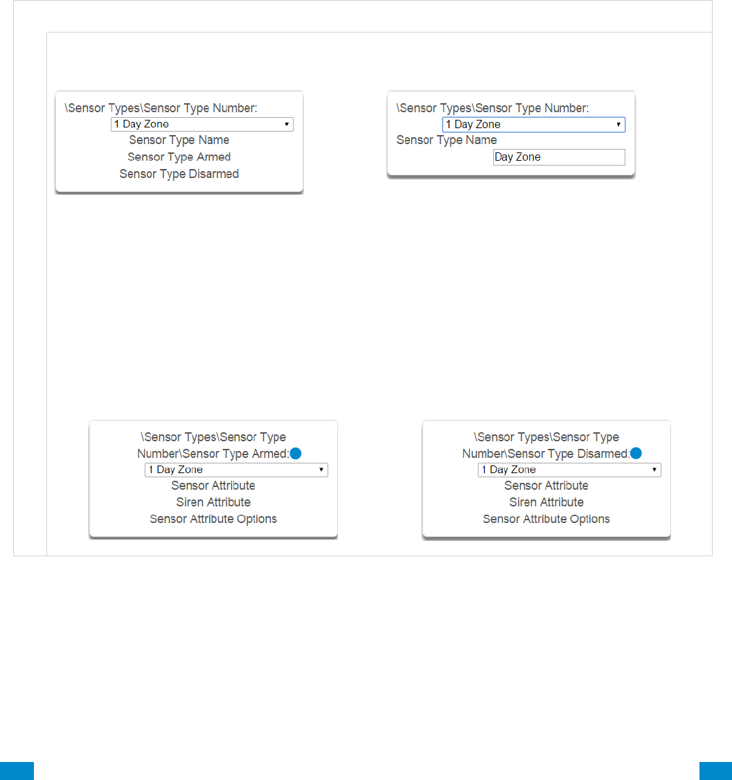
...C... 153 P/N 466-5261 • REV D ISS 17NOV17 UltraSync Modular Hub Reference Manual ©2016 United Technologies Corporation .... .I.....
6.14 Advanced Programming, Sensor Types
Click the Advanced bar and select Sensor Types from the menu to program sensor types
options.
Sensors can be programmed to be one of 32 different sensor configurations (sensor type
profiles). Sensors are fully configurable in the system. These features are considered
advanced programming and should only be changed by an installer with a thorough
understanding of the features.
Sensor type profiles can also change depending on whether the area they are in are armed or
disarmed. This provides the ultimate flexibility in panel programming.
S e n s o r T y p e s S u b m e n u s
Sensor Types Submenus
1 Sensor Type Number (1 – 32)
The system can support a total of 32 Sensor Types.
Each Sensor Type is identified by a unique number,
which cannot be altered, and remains as the key
reference for each Sensor Type.
2 Sensor Type Name
Each Sensor Type can be configured with a custom
32 character name. The name is displayed
wherever a Sensor Type is referenced on the
system.
Sensor type profiles can also change depending on whether the areas they are in
are armed or disarmed. This provides a new level of flexibility in panel programming.
Armed
Disarmed

...C... 154 P/N 466-5261 • REV D ISS 17NOV17 UltraSync Modular Hub Reference Manual ©2016 United Technologies Corporation .... .I.....
Sensor Types Submenus
3 Sensor Type Profile / Armed
Sensor Attribute
This is how the sensor will behave when the area it is in is armed.
• Disabled – sensor is disabled.
• Entry 1 – sensor will follow area entry/exit timer 1.
• Entry 2 – sensor will follow area entry/exit timer 2.
• Follower – instant alarm type unless an entry sensor is tripped first.
• Instant – sensor goes into alarm as soon as it is tripped.
• Trouble Sensor – typically used on fire doors to the exterior of a building. When the system is disarmed
they report trouble and sound a buzzer. When the system is armed they are instant burg alarms.
• Fire – smoke detectors must be wired Normally Open. A short on a fire sensor will create an alarm
condition when the system is armed or disarmed. An open will create a Trouble condition that is always
reported for this sensor type, regardless of the Sensor Trouble reporting option. Keypad sensor LED is
steady for fire condition and flashing for trouble condition. After fire activation, use the keypad to clear &
reset fire sensor by pressing Sensor Reset.
• Holdup delay – when tripped, starts the hold up timer, if the timer is reached then a hold up alarm is sent.
• Holdup reset – when this sensor is tripped, the hold up timer is stopped.
• Keyswitch – A momentary key switch can be used to arm/disarm the panel when it is momentarily
shorted from a closed condition. Use a 3.3K resister for this sensor type. Or if DEOL monitoring is
enabled in System Options, use two 3.3K resistors to allow full line monitoring.
• Event Only – this sensor only creates an event when tripped and is stored in the event log.
Siren Attribute
Select from these 4 options to control what sound the siren makes when this sensor goes into alarm.
• Silent – siren makes no sound
• Fire – temporal three pulse siren
• Yelping – siren makes a yelping sound
• Four Pulse – temporal four pulse siren
4 Sensor Type Profile / Disarmed
This is how the sensor will behave when the area it is in is disarmed.
• Disabled – sensor is disabled.
• Instant – sensor goes into alarm as soon as it is tripped.
• Trouble Sensor – typically used on fire doors to the exterior of a building. When the system is disarmed
they report trouble and sound a buzzer. When the system is armed they are instant burg alarms.
• Fire – smoke detectors must be wired Normally Open. A short on a fire sensor will create an alarm
condition when the system is armed or disarmed. An open will create a Trouble condition that is always
reported for this sensor type, regardless of the Sensor Trouble reporting option. Keypad sensor LED is
steady for fire condition and flashing for trouble condition. After fire activation, use the keypad to clear &
reset fire sensor by pressing Sensor Reset.
• Holdup delay – when tripped, starts the hold up timer, if the timer is reached then a hold up alarm is sent.
• Holdup reset – when this sensor is tripped, the hold up timer is stopped.
• Keyswitch – A momentary key switch can be used to arm/disarm the panel when it is momentarily
shorted from a closed condition. Use a 3.3K resister for this sensor type. Or if DEOL monitoring is
enabled in System Options, use two 3.3K resistors to allow full line monitoring.
• Event Only – this sensor only creates an event when tripped and is stored in the event log.
Siren Attribute
See descriptions above. This is how the siren will behave when the area it is in is disarmed.
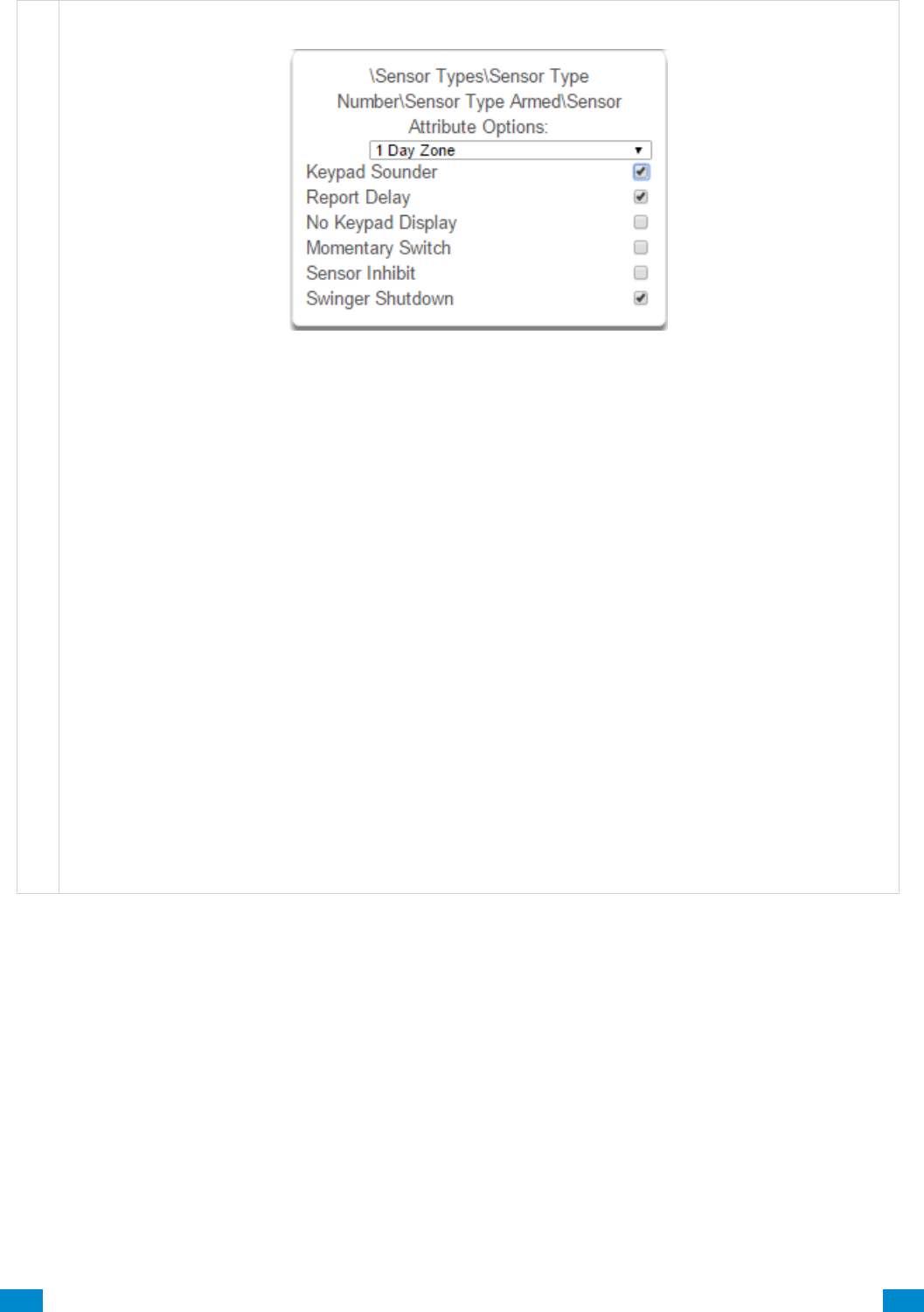
...C... 155 P/N 466-5261 • REV D ISS 17NOV17 UltraSync Modular Hub Reference Manual ©2016 United Technologies Corporation .... .I.....
Sensor Types Submenus
5 Sensor Attribute Options (Armed or Disarmed)
• Keypad Sounder – If enabled, the panel will announce alarm, tamper, or trouble conditions. Default is
on.
• Report Delay – if enabled, the system will delay reporting sensor activations until the next scheduled
report. This setting is ignored if the sensor is a Fire type and sensor activations are reported immediately.
When disabled sensor activations (trip, bypass and restorals) are reported immediately. Default is off.
• No Keypad Display – if enabled, any sensor conditions such as alarm and tamper will not illuminate the
Alarm Light. Conditions will still report and function as normal. Default is off.
• Momentary Switch – if enabled, the sensor will not latch. If it is triggered again then it will send another
report immediately. Default is off.
• Sensor Inhibit (Bypass) – This feature is designed to reduce false alarms at arming/disarming. If
enabled, a sensor that is currently faulted that could cause an alarm condition will be temporarily
bypassed when changing armed states.
This typically occurs when forced arming and the sensor is open, or when a schedule change occurs that
changes the sensor type. The bypass will be applied to the sensor if it remains open at the end of the exit
timer. Default is off.
• Swinger Shutdown
Swinger Shutdown is a false alarm prevention feature that counts the number of alarms caused by a
specific sensor.
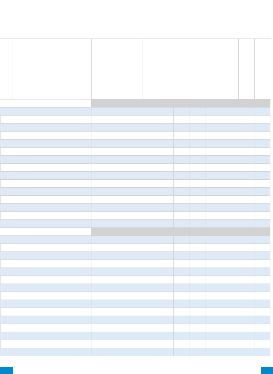
...C... 156 P/N 466-5261 • REV D ISS 17NOV17 UltraSync Modular Hub Reference Manual ©2016 United Technologies Corporation .... .I.....
Sensor Types Table
Note: When initiating Away arming, a sensor with the default sensor attributes of Entry 1,
Entry 2 and Follower must be tripped during the exit delay to arm the system in the Away
mode. If one of these sensors is not tripped during the exit delay the system will arm in the
Stay mode. (CP-01 requirement)
Armed
1
Day Zone
Instant
Yelping
Y
Y
N
N
N
Y
2
24 Hour Audible
Instant
Yelping
Y
Y
N
N
N
Y
3
Entry Exit Delay 1
Entry 1
Yelping
Y
Y
N
N
N
Y
4
Entry Exit Delay 2
Entry 2
Yelping
Y
Y
N
N
N
Y
5
Follower
Follower
Yelping
Y
Y
N
N
N
Y
6
Instant
Instant
Yelping
Y
Y
N
N
N
Y
7
24 Hour Silent
Instant
Silent
N
Y
N
N
N
Y
8
Fire Alarm
Fire
Fire
Y
N
N
N
N
N
9
Entry Exit Delay 1 Auto-Bypass
Entry 1
Yelping
Y
Y
N
N
Y
Y
10
Entry Exit Delay 2 Auto-Bypass
Entry 2
Yelping
Y
Y
N
N
Y
Y
11
Instant Auto-Bypass
Instant
Yelping
Y
Y
N
N
Y
Y
12
Event Only
Event Only
Silent
N
N
Y
N
N
N
13
Momentary Key Switch
Keyswitch
Silent
N
N
N
Y
N
N
14
Latching Key Switch
Keyswitch
Silent
N
N
N
N
N
N
15
CO Detector
Instant
Four Pulse
Y
N
N
N
N
N
Disarmed
1
Day Zone
Trouble Sensor
Yelping
Y
N
N
N
N
N
2
24 Hour Audible
Instant
Yelping
Y
Y
N
N
N
Y
3
Entry Exit Delay 1
Event Only
Silent
N
N
N
N
N
N
4
Entry Exit Delay 2
Event Only
Silent
N
N
N
N
N
N
5
Follower
Event Only
Silent
N
N
N
N
N
N
6
Instant
Event Only
Silent
N
N
N
N
N
N
7
24 Hour Silent
Instant
Silent
N
Y
N
N
N
Y
8
Fire Alarm
Fire
Fire
Y
N
N
N
N
N
9
Entry Exit Delay 1 Auto-Bypass
Event Only
Silent
N
N
N
N
N
N
10
Entry Exit Delay 2 Auto-Bypass
Event Only
Silent
N
N
N
N
N
N
11
Instant Auto-Bypass
Event Only
Silent
N
N
N
N
N
N
12
Event Only
Event Only
Silent
N
N
Y
N
N
N
13
Momentary Key Switch
Keyswitch
Silent
N
N
N
Y
N
N
14
Latching Key Switch
Keyswitch
Silent
N
N
N
N
N
N
15
CO Detector
Instant
Four Pulse
Y
N
N
N
N
N
Preset Number
Preset Name
Sensor Attribute
Siren Attribute
Keypad Sounder
Report delay
No Keypad Display
Momentary Switch
Sensor Inhibit (Bypass)
Swinger Shutdown
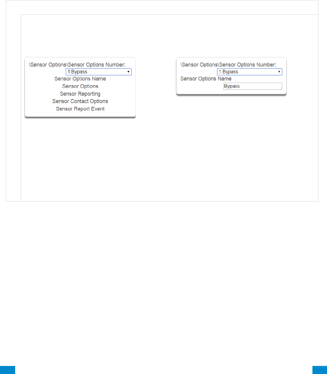
...C... 157 P/N 466-5261 • REV D ISS 17NOV17 UltraSync Modular Hub Reference Manual ©2016 United Technologies Corporation .... .I.....
6.15 Advanced Programming, Sensor Options
Click the Advanced bar and select Sensor Options from the menu to program sensor options.
Sensors are fully configurable in the system. These features are considered advanced
programming and should only be changed by an installer with a thorough understanding of the
features.
S e n s o r O p t i o n s S u b m e n u s
S e n s o r O p t i o n s S u b m e n u s
1 Sensor Options Number (1 – 32)
The system can support a total of 32 Sensor
Options. Each Sensor Option is identified by a
unique number, which cannot be altered, and
remains as the key reference for each Sensor
Option.
2 Sensor Options Name
Each Sensor Option can be configured with a
custom 32 character name. The name is displayed
wherever a Sensor Option is referenced on the
system.
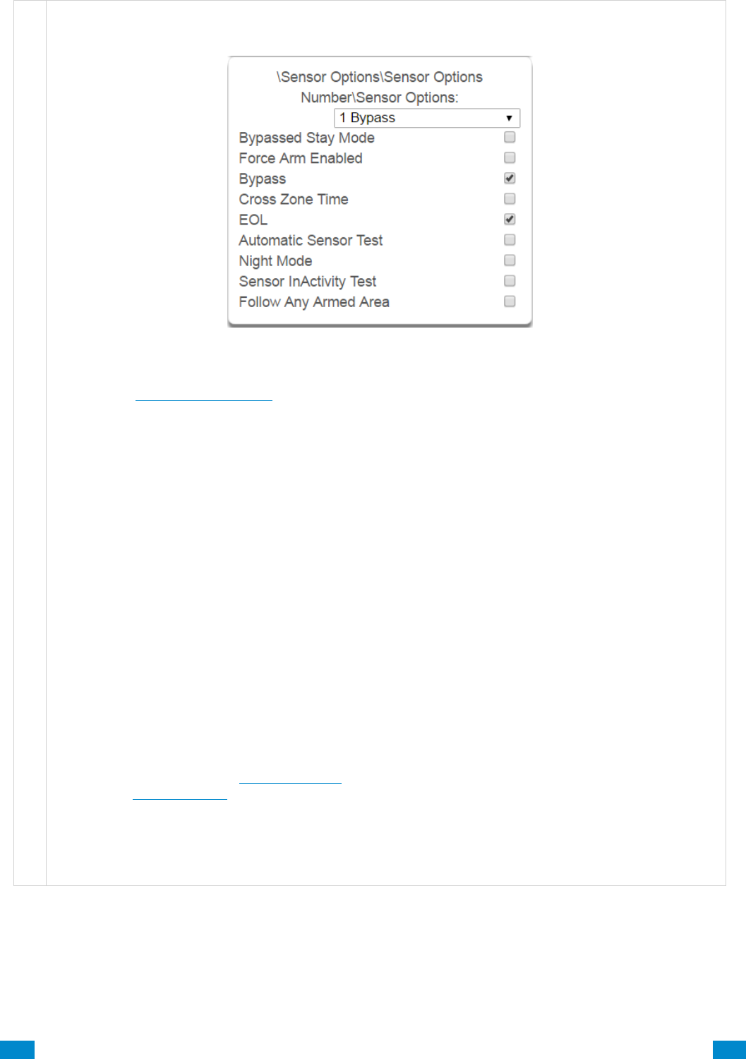
...C... 158 P/N 466-5261 • REV D ISS 17NOV17 UltraSync Modular Hub Reference Manual ©2016 United Technologies Corporation .... .I.....
S e n s o r O p t i o n s S u b m e n u s
3 Sensor Options
Also see the Sensor Options Table for reference.
Bypassed Stay Mode – if enabled, this sensor is automatically bypassed when the area is armed in
stay mode. For example, it is an interior sensor.
Force Arm Enabled – if enabled, this sensor type may be open while arming if forced arming is
enabled in the area options. Normally all sensors in an area must be closed before a user can attempt
to arm that area.
Bypass – if enabled, this sensor may be bypassed.
Cross Zone– This sensor type will require two triggers or another sensor would have to have been
trigged before it will activate an alarm.
EOL – Enable End Of Line resistor tamper monitoring
Automatic Sensor Test – if enabled, this test is controlled by action results automatic test on and off.
Night Mode – If enabled, sensor is bypassed in Stay Mode or Instant Stay Mode, and active in Stay
Night Mode
Sensor Inactivity Test – if enabled, this sensor will check for Sensor Inactivity. The Sensor Inactivity
setting must be enabled in General Options. The time is programmed in Advanced Programming,
System – System Timers. See Programming the System, Section 5.4.
Follow Any Armed Area – If enabled, and a sensor is in more than 1 area it will create an alarm if
triggered when any area is armed. If this feature is off then all the areas must be armed before the
sensor will become active.

...C... 159 P/N 466-5261 • REV D ISS 17NOV17 UltraSync Modular Hub Reference Manual ©2016 United Technologies Corporation .... .I.....
S e n s o r O p t i o n s S u b m e n u s
4 Sensor Reporting
• Alarms Reporting – if enabled, this sensor will
report alarms.
• Alarm Restores Reporting – if enabled, this
sensor will report alarm restores.
• Bypass-Unbypass Reporting – if enabled, this
sensor will report bypasses and unbypass
restorals.
• Sensor Lost-Low Battery Reporting – if enabled,
this sensor will report loss of wireless supervision
and low battery faults.
• Sensor Trouble and Restore – if enabled, this
sensor will report sensor trouble and restorals.
Fire type sensors will always report regardless of
this option.
5 Sensor Contact Options
(Applies to the hardwire inputs, not wireless
sensors.)
• Normally Open – if enabled, the sensor circuit is
normally open. Default is off.
• Fast Loop – if enabled, the system will be more
sensitive and respond quicker to a change in
state to the sensor. For example, we could
enable this on a door contact to trigger the
turning on of lights quicker when someone
opens the door by using an Action. Depending
on the application this may increase the chance
of a false alarm if the sensor is used for intrusion
detection.
6 Sensor Report Event
From the drop down menu, select the CID and SIA event code to report when this sensor is tripped.

...C... 160 P/N 466-5261 • REV D ISS 17NOV17 UltraSync Modular Hub Reference Manual ©2016 United Technologies Corporation .... .I.....
Sensor Options Table
Preset Number
Preset Name
Bypassed Stay Mode
Forced Arm Enabled
Bypass
Cross Zone Time
EOL
Automatic Sensor Test
Night Mode
Sensor Inactivity Test
Follow Any Armed Area
Alarms reporting
Alarm restore reporting
Bypass-Unbypass reporting
Sensor reporting
Lost-Low Battery
Sensor reporting
Trouble and Restore
Normally Open
Fast Loop
Sensor Report Event
1
Bypass
x
x
x
x
x
x
x
134:BA
2
Bypass Stay
x
x
x
x
x
x
x
x
132:BA
3
Bypass – Forced Arm
x
x
x
x
x
x
x
x
134:BA
4
Bypass – Cross Zone
x
x
x
x
x
x
x
x
134:BA
5
Fire
x
x
x
x
x
x
x
110:FA
6
Panic
x
x
x
x
x
x
x
120:PA
7
Silent Panic
x
x
x
x
x
x
122:HA
8
Normally Open no EOL
x
x
x
x
x
x
x
130:BA
9
Normally Closed no EOL
x
x
x
x
x
x
130:BA
10
Gas Detected
x
x
x
x
x
x
151:GA
11
High Temp
x
x
x
x
x
x
158:KA
12
Water Leakage
x
x
x
x
x
x
154:WA
13
Low Temp
x
x
x
x
x
x
159:ZA
14
High Temp
x
x
x
x
x
x
158:KH
15
Fire Alarm Pull Station
x
x
x
x
x
x
110:FA
16
Night Mode
x
x
x
x
x
x
x
x
x
135:BA
17
Blank
x
x
x
x
x
x
x
x
130:BA
18
Blank
x
x
x
x
x
x
x
x
130:BA
19
Blank
x
x
x
x
x
x
x
x
130:BA
20
Blank
x
x
x
x
x
x
x
x
130:BA
21
Blank
x
x
x
x
x
x
x
x
130:BA
22
Blank
x
x
x
x
x
x
x
x
130:BA
23
Blank
x
x
x
x
x
x
x
x
130:BA
24
Blank
x
x
x
x
x
x
x
x
130:BA
25
Blank
x
x
x
x
x
x
x
x
130:BA
26
Blank
x
x
x
x
x
x
x
x
130:BA
27
Blank
x
x
x
x
x
x
x
x
130:BA
28
Blank
x
x
x
x
x
x
x
x
130:BA
29
Blank
x
x
x
x
x
x
x
x
130:BA
30
Blank
x
x
x
x
x
x
x
x
130:BA
31
Blank
x
x
x
x
x
x
x
x
130:BA
32
Blank
x
x
x
x
x
x
x
x
130:BA
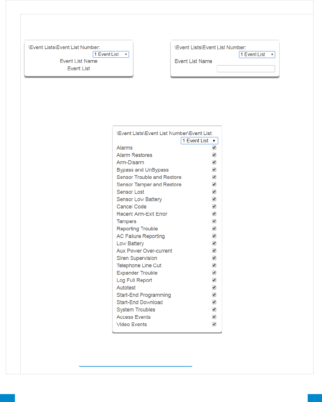
...C... 161 P/N 466-5261 • REV D ISS 17NOV17 UltraSync Modular Hub Reference Manual ©2016 United Technologies Corporation .... .I.....
6.16 Advanced Programming, Event Lists
Click the Advanced bar and select Event Lists from the menu to program event lists options.
Event Lists are monitored by Channels to determine if they should be reported. Only events
on a Channel’s associated Event List will be reported.
E v e n t L i s t s S u b m e n u s
E v e n t L i s t s S u b m e n u s
1 Event List Number (1 – 16)
The system can support a total of 16 Event Lists.
Each Event List is identified by a unique number,
which cannot be altered, and remains as the key
reference for each Event List.
2 Event List Name
Each Event List can be configured with a custom
32 character name. The name is displayed
wherever an Event List is referenced on the
system.
3 Event List
Select the events that you want to be part of this Event List. If an event message is on an Event List then
the Channel will attempt to deliver it. If an event message is not on the Event List assigned to that
Channel, it will not attempt delivery even if the message has been sent to it. See how Channel Groups
handle event lists in Advanced Programming, Channel Groups.

...C... 162 P/N 466-5261 • REV D ISS 17NOV17 UltraSync Modular Hub Reference Manual ©2016 United Technologies Corporation .... .I.....
6.17 Advanced Programming, Channel Groups
Click the Advanced bar and select Channel Groups from the menu to program channel
groups options.
The system provides you powerful and flexible reporting capability through its Channel
feature. They are fully configurable to suit your needs by allowing you to specify what events
to report to single and multiple destinations, with multiple levels of back up paths.
Channel Groups Submenus
Channel Groups Submenus
1 Channel Group Number (1 – 16)
The system can support a total of 16 Channel
Groups. Each Channel Groups is identified by a
unique number, which cannot be altered, and
remains as the key reference for each Channel
Group.
2 Channel Group Name
Each group can be configured with a custom 32
character name. The name is displayed wherever an
Action Group is referenced on the system.
3 Channel List
For each Channel Group, select the Channels where the event should be sent.
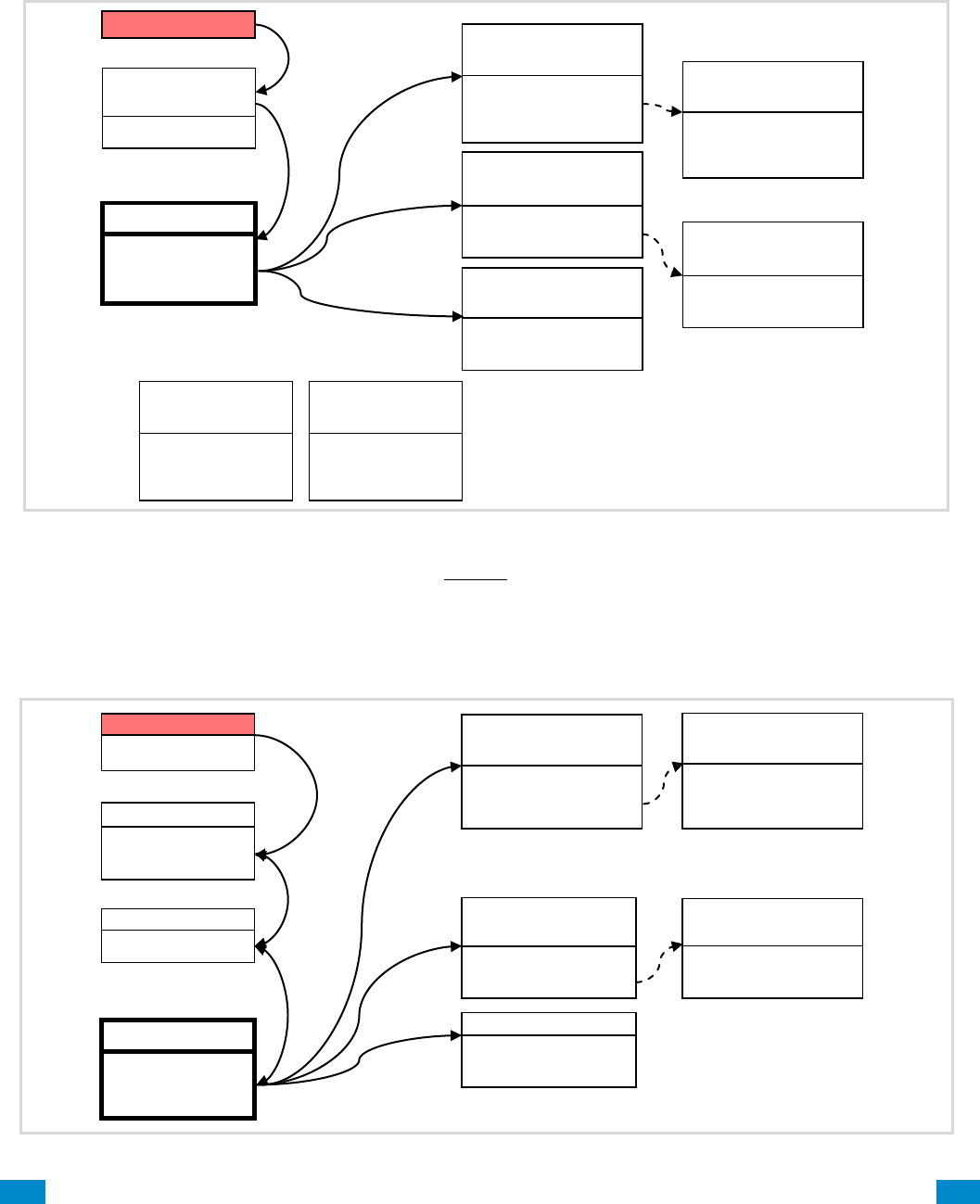
...C... 163 P/N 466-5261 • REV D ISS 17NOV17 UltraSync Modular Hub Reference Manual ©2016 United Technologies Corporation .... .I.....
When a system event occurs, it is routed to the System Event Channel Group
(Communicator\System Event Reporting\System Channels). The Channel Group will forward
the event to each of the Channels it contains. If the event is on the Channel’s Event List, the
Channel will attempt to send the event to the Channel’s destination.
Example System Event
If a sensor event or area event is generated, then the event is sent to the Channel Group
specified (Area – Channel Group) in the lowest area the sensor belongs to. The Channel
Group forwards the event to each of the Channels it contains. Each Channel checks its Event
List to determine if the event should be sent.
Example Sensor or Area Event
Channel Group
sends event
to every
Channel it contains
Channel Group 1
Channel 1
Channel 2
Channel 3
AC Fail
Channel Group 1
System Event
Reporting
Channel 2
Control Room 2
Event List = 1
Next Channel = 5
Channel 3
Email
Event List = 2
Next Channel = 0
Channel 1
Control Room 1
Event List = 1
Channel Attempts = 3
Next Channel = 4
System sends
event to
Channel Group
Channel 5
Control Room 2
Event List = 1
Next Channel = 0
Channel 4
Control Room 1
Event List = 1
Channel Attempts = 3
Next Channel = 0
Channels 1 and 2 will attempt to send the event as AC Fail is on the
corresponding Event List. Back up channels 4 and 5 will also attempt
to send the event if they are used.
Channel 3 will NOT send the event as Event List 2 does not include
AC Fail events.
Event List 1
Critical
Alarms
Bypass & Restore
AC Fail
Event List 2
Informational
Open & Closes
Auto test
Channel Group 1
Channel 1
Channel 2
Channel 3
Sensor 3 in Alarm
Area Group = 1
Area Group 1
Area 1
Area 2
Channel Group 1
Area 1
Sensor sends alarm to area group
Event sent to lowest area
Area sends event
to Channel Group
Channel Group sends Event
to every Channel It contains
Channel 3 Email
Event List = 2
Next Channel = 0
Channel 2
Control Room 2
Event List = 1
Next Channel = 5
Channel 1
Control Room 1
Event List = 1
Channel Attempts = 3
Next Channel = 4
Channel checks to see if the
event is on its Event List; if
yes it will attempt to send, if
not it will stop.
Channel 5
Control Room 2
Event List = 1
Next Channel = 0
Channel 4
Control Room 1
Event List = 1
Channel Attempts = 3
Next Channel = 0
If it does not succeed after
Channel Attempts, it will try
sending on the next Channel.
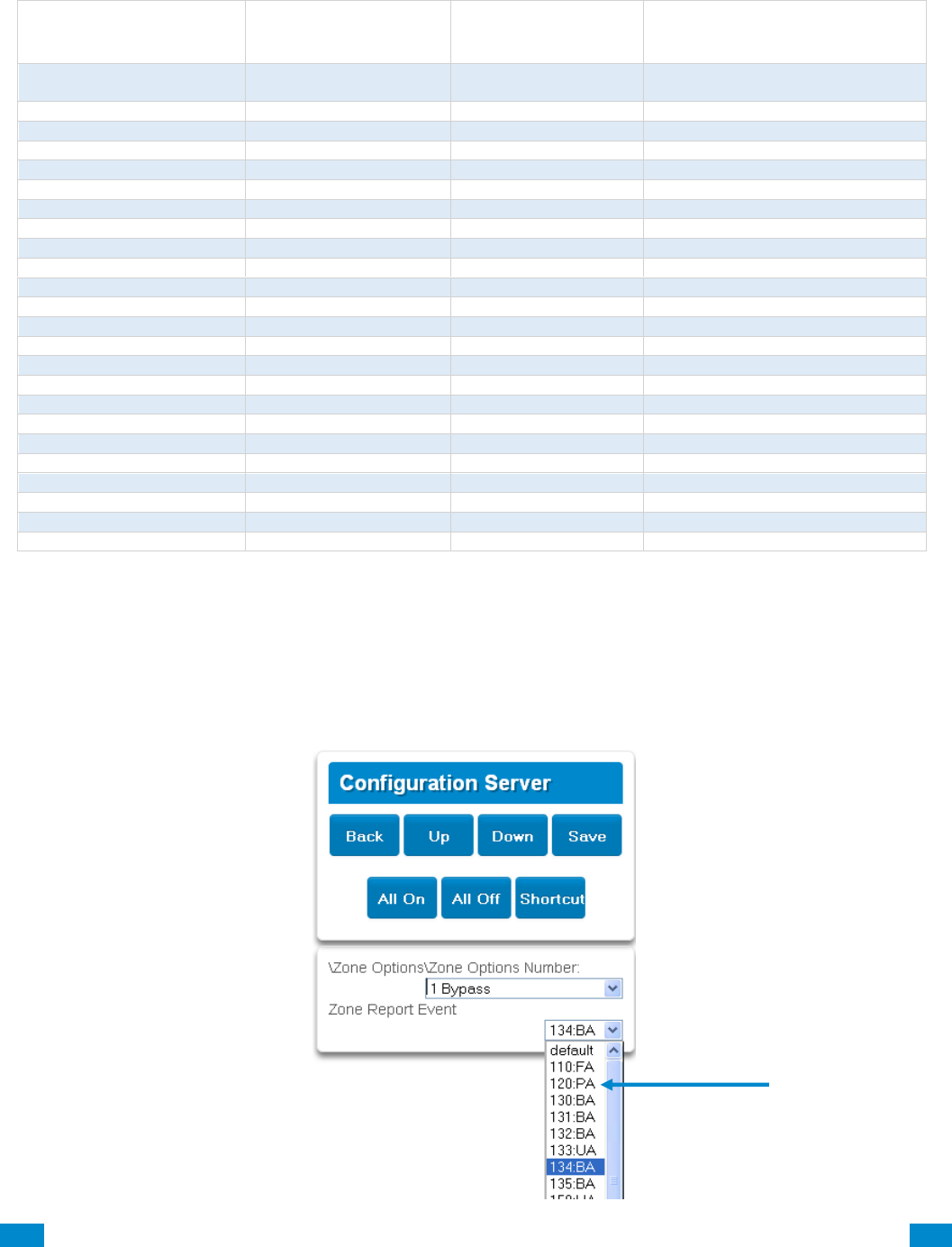
...C... 164 P/N 466-5261 • REV D ISS 17NOV17 UltraSync Modular Hub Reference Manual ©2016 United Technologies Corporation .... .I.....
Customize Reporting Codes
The system has the ability to report Ademco Contact I.D. transmissions. Each report in
Contact I.D. consists of an event code and the sensor I.D. generating the alarm.
Programmed Event Code
Contact I.D. Code
SIA Event
Code
Description
0
Use default code for
Sensor Type
Use default code for
Sensor Type
1
110
FA
Fire Alarm
2
120
PA
Panic Alarm
3
130
BA
Burglary Alarm
4
131
BA
Perimeter Alarm
5
132
BA
Interior Alarm
6
133
UA
24 Hour (Safe)
7
134
BA
Entry/Exit Alarm
8
135
BA
Day/Night Alarm
9
150
UA
Non Burglary 24 Hour
10
121
HA
Duress Alarm
11
122
HA
Silent Panic
12
100
MA
Auxiliary Alarm
13
123
PA
Audible Panic Alarm
14
137
TA
Tamper Alarm
15
602
RP
Periodic Test
16
151
GA
Gas Detected
17
158
KA
High Temp
18
154
WA
Water Leakage
19
140
QA
General Alarm
20
140
SA
General Alarm
21
159
ZA
Low Temp
22
158
KH
High Temp
23
115
FA
Fire Alarm Pull Station
Customize the code reported by following these steps:
1. Login to the Web Server
2. Press Advanced\Sensor Options.
3. Select the Sensor Options you want to change.
4. Press Sensor Report Event.
5. Select the desired Contact I.D.\SIA Event Code pair from the drop down menu.
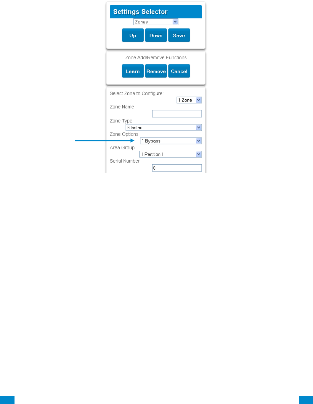

...C... 166 P/N 466-5261 • REV D ISS 17NOV17 UltraSync Modular Hub Reference Manual ©2016 United Technologies Corporation .... .I.....
Reporting Fixed Codes in Contact I.D.
The table below lists the CID event codes sent for the following reports (if enabled). The
number in brackets following the event is the number that will be reported as the sensor
number if extended Contact I.D. is enabled in the system options. Otherwise sensor ‘0’ will
always be reported. If there are no parentheses, the sensor will be reported as ‘0’.
Report
Contact I.D. Event
Manual Test
601
Auto test Open (user number)
602
Close (user number)
401
Cancel (user number)
406
Download Complete
412
Start Program
627
End Program
628
Ground Fault
310
Ground Fault Restore
310
Recent Close (user number)
401
Exit Error (user number)
457
Event Log Full
605
Fail To Communicate
354
Expander Trouble
333
Expander Restore
333
Telephone Fault
351
Telephone Restore
351
Siren Tamper
321
Siren Restore
321
Aux Power Over Current
312
Aux Power Restore
312
Low Battery
309
Low Battery Restore
309
AC Fail
301
AC Restore
301
Box Tamper
137
Box Tamper Restore
137
Panel Tamper
137
Panel Panic
120
Duress
121
Panel Fire
110
Panel Auxiliary
100
RF Sensor Lost (sensor number)
381
RF Sensor Restore (sensor number)
381
Sensor Low Battery (sensor number)
384
Sensor Battery Restore (sensor number)
384
Sensor Trouble (sensor number)
380
Sensor Trouble Restore (sensor number)
380
Sensor Tamper (sensor number)
137
Sensor Tamper Restore (sensor number)
137
Sensor Bypass (sensor number)
570
Bypass Restore (sensor number)
570
Sensor Inactivity
391
Late To Close
454
Forced Door
423
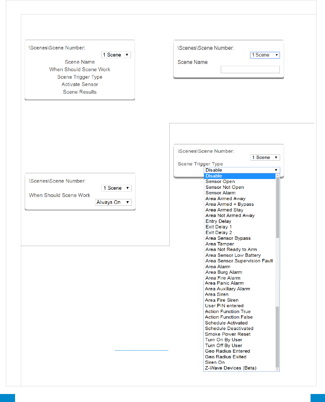
...C... 167 P/N 466-5261 • REV D ISS 17NOV17 UltraSync Modular Hub Reference Manual ©2016 United Technologies Corporation .... .I.....
6.18 Advanced Programming, Action Groups
Reserved: Future content.
6.19 Advanced Programming, Scenes
Click the Advanced bar and select Scenes from the menu to program scenes options.
r
S c e n e s S u b m e n us
S c e n e s S u b m e n u s
1 Scene Number (1 – 16)
The system can support a total of 16 Scenes.
Each Scene is identified by a unique number,
which cannot be altered, and remains the key
reference for each Scene.
3 When Scene Should Work
Select the Schedule that controls when this Scene
is active. If the current date and time is outside of
the selected schedule, then the Scene will not run.
Select the event that will trigger the Scene.
Note: If you want to trigger a scene with:
User PIN entered
Turn On By User
Turn Off By User
you must first enable Log PIN Use.
To enable, see Permission Options.
2 Scene Name
Each group can be configured with a custom 32
character name. The name is displayed wherever
an Action Group is referenced on the system.
4 Scene Trigger Type List
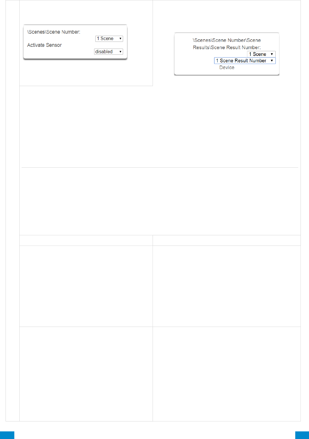
...C... 168 P/N 466-5261 • REV D ISS 17NOV17 UltraSync Modular Hub Reference Manual ©2016 United Technologies Corporation .... .I.....
S c e n e s S u b m e n u s
5 Activate Sensor
Select which sensor will provide the trigger for
the Scene.
6 Scene Results Number/ Device
Each scene can trigger up to 16 scene actions when a certain condition is met. A scene can be triggered
manually, through a schedule, or via a system event. These are simplified actions that allow you to control
devices on your system. There are two types of Scene Action - Alarm System Action and Z-Wave Device
Action.
1. Alarm System Action
2. Result Type - The event of the Action Result to perform. Reference the Scene Action and Scene
Action Events Types table below.
3. Result Number - Select the area / scene / camera number to control.
1. Z-Wave Device Action
To display Z-Wave Action Types you must first learn in a Z-Wave device. The Z-Wave device name will
then appear.
2. Device – select the Z-Wave device you want to control.
3. Z-Wave Type 8 Setting 1 – depends on Z-Wave device. May include options such as On, Off, Heat,
Cool, Auto, Up, Down, Lock, Unlock.
Scene Action
Action Event Type
Alarm System Action
Disabled
Sensor Bypass
Turn On Away
Turn Off
Armed Stay
Reset AutoArm Timer
Armed Away, No Auto Stay
Chime On
Chime Off
Activate Scene
Trigger Camera Video Clip
Z-Wave Device Action
The available functions depend on the Z-Wave
device(s) installed. Here are some examples:
Disabled
On
Off
Heat
Cool
Auto
Cool Set Point
Heat Set Point
Lock
Unlock
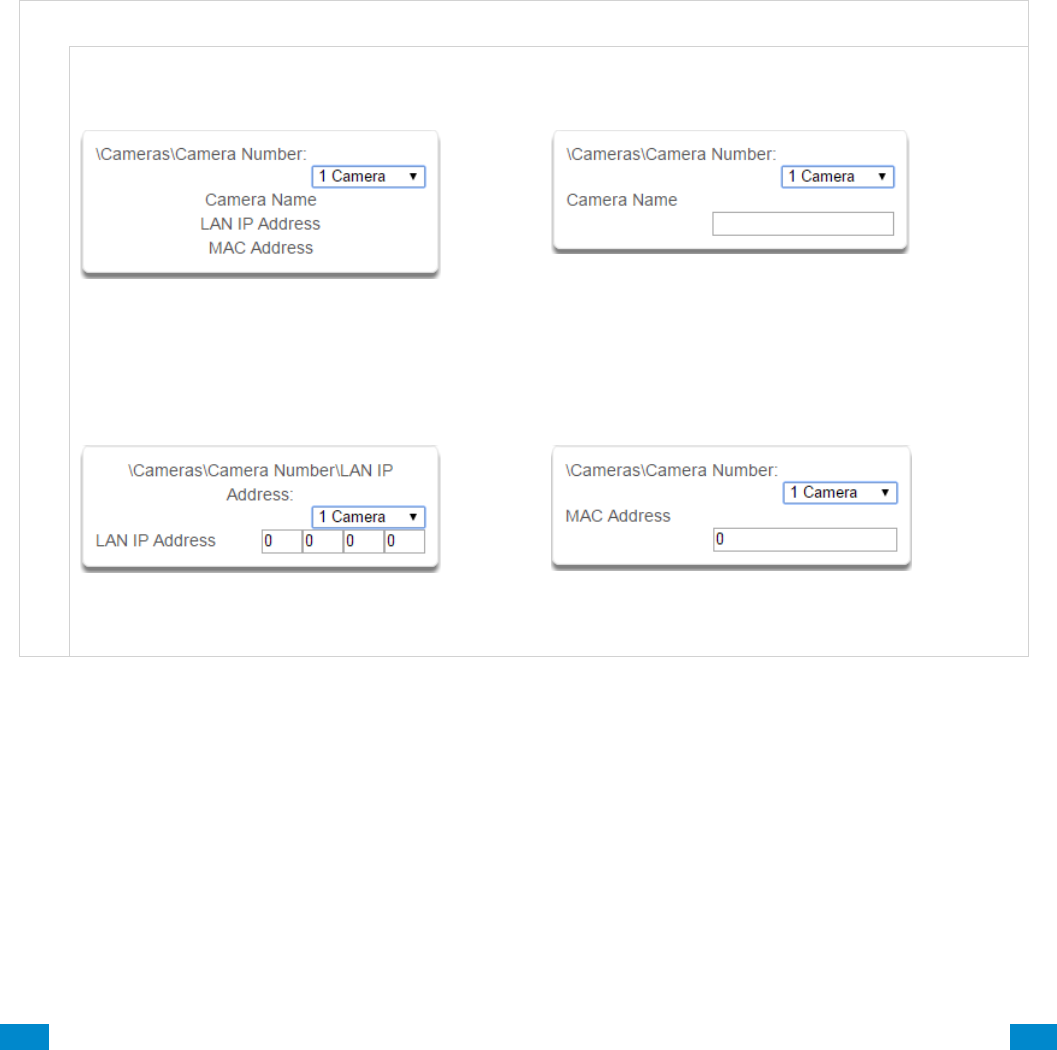
...C... 169 P/N 466-5261 • REV D ISS 17NOV17 UltraSync Modular Hub Reference Manual ©2016 United Technologies Corporation .... .I.....
6.20 Advanced Programming, Speech Tokens
Reserved: Future content.
6.21 Advanced Programming, Cameras
Click the Advanced bar and select Cameras from the menu to program cameras options.
Add a Camera Method 2 – Manual Entry
1. Enter a name for the camera.
2. Enter the IP address and MAC address (Submenus 3, 4 below).
3. Press Save.
4. Your camera will now be viewable from the Web Server and UltraSync app.
C a m e r a s S u b m e n u s
C a m e r a s S u b m e n u s
1 Camera Number (1-16)
Choose the Camera Number
2 Camera Name
Assign Camera Number a Name
3 Camera LAN IP Address
Assign a Camera a LAN IP address
4 Camera MAC Address
Assign a Camera a MAC address
Removing a Camera
1. Select the camera you wish to remove.
2. Delete the IP address and MAC address (Submenus 3, 4 above).
3. Press Save.
4. Your camera will no longer be accessible from the system.
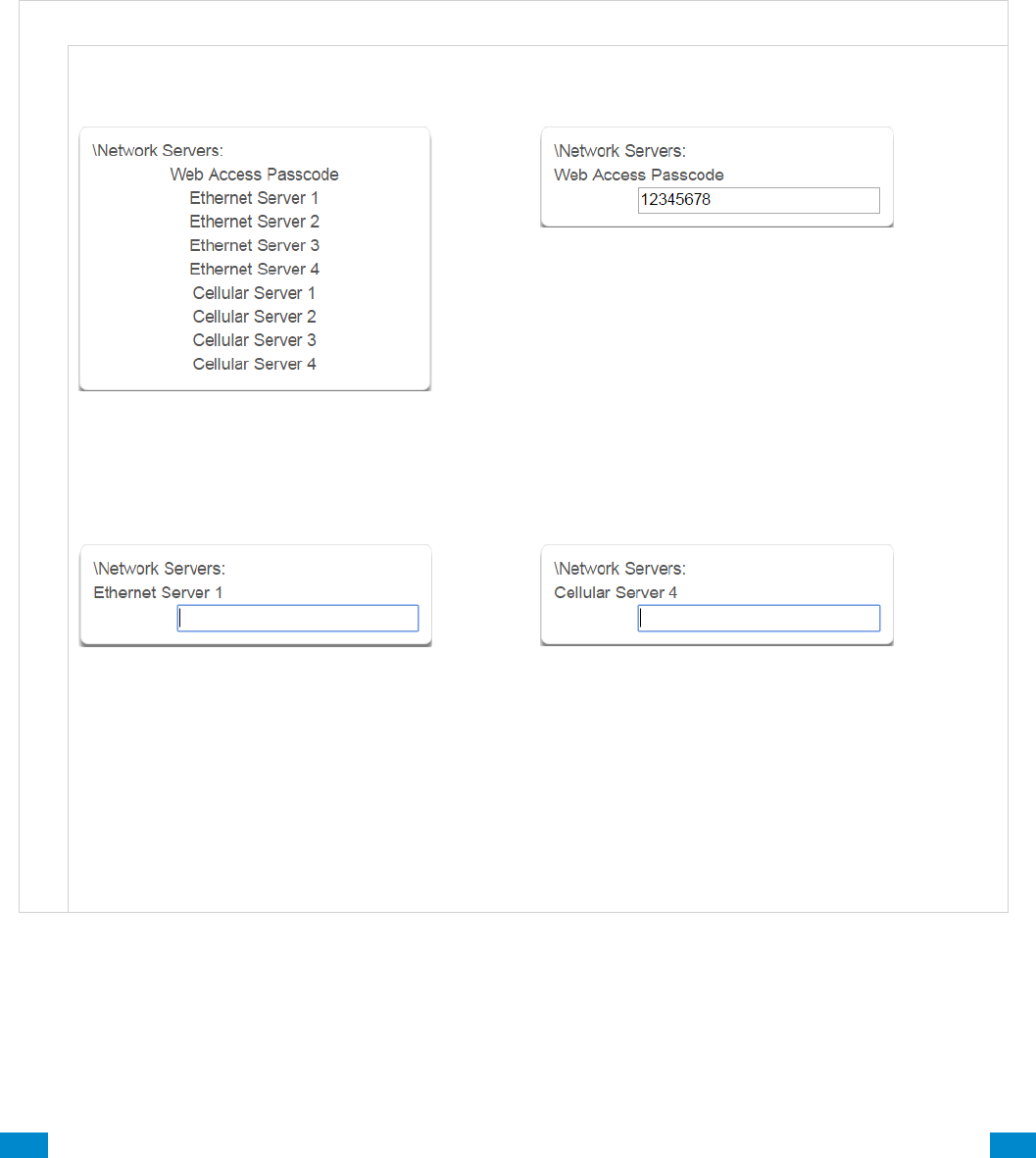
...C... 170 P/N 466-5261 • REV D ISS 17NOV17 UltraSync Modular Hub Reference Manual ©2016 United Technologies Corporation .... .I.....
6.22 Advanced Programming, Network Servers
Click the Advanced bar and select Network Servers from the menu to program network
server options.
The system will establish a secure VPN connection to Network Servers to allow simplified set
up and configuration of email reporting and remote access features.
The server addresses are pre-programmed and SHOULD NOT be modified unless you are
instructed to by technical support staff.
N e t w o r k S e r v e r s S u b m e n u s
N e t w o r k S e r v e r s S u b m e n u s
1 Passcode and Servers
2 Web Access Passcode
This 8 digit code is required to allow remote access
to your system via a smartphone app. Set this to
00000000 to disable this feature.
3 Ethernet Servers (1-4)
Ethernet Server 1 -
The IP address or server name of the primary
Ethernet server.
Ethernet Servers 2 - 4
The IP address or server names of the backup
Ethernet servers.
4 Cellular Servers
Cellular Server 1 -
The IP address or server name of the primary
wireless server.
Cellular Servers 2 - 4
The IP address or server names of the backup
cellular servers.

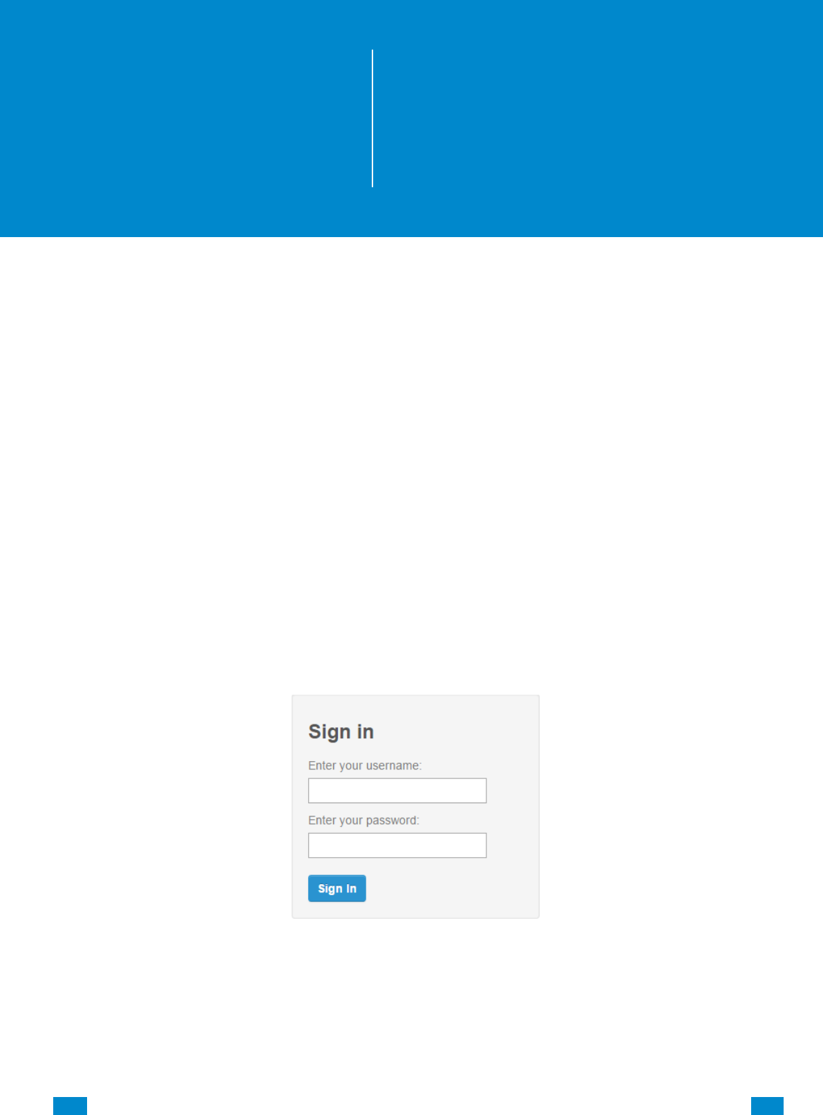
...C... 172 P/N 466-5261 • REV D ISS 17NOV17 UltraSync Modular Hub Reference Manual ©2016 United Technologies Corporation .... .I.....
7 Users and Permissions
A user is a system operator that is granted the authority to control and or configure the
system. The Users menu is where you add, delete or modify one of the 256 users.
Each user is assigned a PIN code and a user number. This allows them to interact with the
system.
Users will typically interact with the system via a keypad or wireless keyfob(s) for tasks such
as arming and disarming an area, bypassing a sensor. Permissions can be granted to a user
to perform tasks such as adding sensors, modifying schedules or deleting users.
Users can only edit users with the same or less authority than them. If a user attempts to
access a user with a higher level of access (e.g. to more menus or more areas) then the
system will deny access.
7.1 Add Users
Connect to the Web Server. The login screen should appear:
Enter your username and password. A master User PIN is required to add users, by default
this is “User 1” and “1–2–3–4”, then press Sign In.
Press Users. The following screen appears:
7
REFERENCE GUIDE
UltraSync
Modular Hub
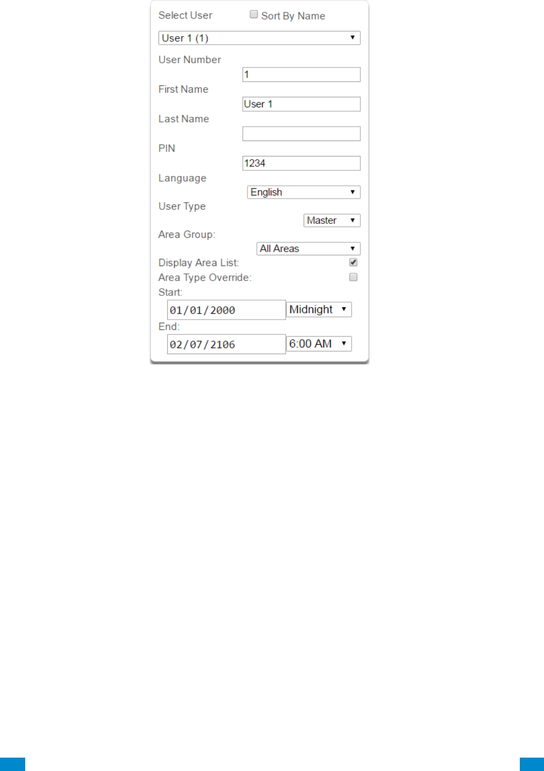
...C... 173 P/N 466-5261 • REV D ISS 17NOV17 UltraSync Modular Hub Reference Manual ©2016 United Technologies Corporation .... .I.....
User Menu:
Enter a First and/or Last Name.
Enter a unique PIN code between 4 and 8 digits.
Select a User Type:
Standard users can arm and disarm areas; they cannot create users or review event
history.
Master users can arm and disarm areas. They can create, delete, or modify user codes.
They can also change system settings.
Arm Only users can only turn on the security system; they cannot disarm, or dismiss any
system conditions.
Duress users will send a duress event when they are used to arm or disarm the system.
Custom users can have additional permissions and settings configured.
Display Area List When this feature is enabled on a multi-area system and this user
requests to arm/disarm the system from the main screen of the keypad, the keypad will
display the area control screen that will allow them to arm individual areas. If this feature
is disabled, the keypad will automatically arm/disarm all areas.
Press Save.
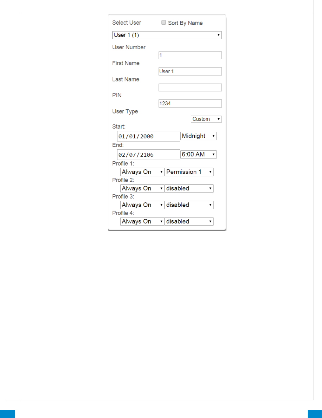
...C... 174 P/N 466-5261 • REV D ISS 17NOV17 UltraSync Modular Hub Reference Manual ©2016 United Technologies Corporation .... .I.....
7.2 Users Submenus
The following submenus describe the features associated with the Users Menu.
U s e r S u b m e n u s
U s e r S u b m e n u s
User First Name
Each user can be configured with a custom 16 character first name. The user name descriptor may be
displayed in the event log, keypad and when remotely connected to the system via the management
software.
User Last Name
Each user can be configured with a custom 16 character last name. The user name descriptor may be
displayed in the event log, keypad and when remotely connected to the system via the management
software.
User Number
The system will store a number of users relative to the model type and the amount of memory installed.
Unlike other systems, user numbers are not predefined and can be configured from user number 1 to
1000 as long as user numbers are not duplicated and do not exceed the total number of users that can
fit the allocated memory.
User PIN
Users can be configured with 4 to 8 digit PIN. The user PIN is required by the system to determine the
user number and the users associated permissions system control and configuration. Any number of
users can have any digit length from 4 to 8 digits.

...C... 175 P/N 466-5261 • REV D ISS 17NOV17 UltraSync Modular Hub Reference Manual ©2016 United Technologies Corporation .... .I.....
U s e r S u b m e n u s
User Type
User Type provides quick configuration of user permissions. The available user types are:
1. Standard – Standard users can only change their own PIN codes and cannot change the settings of the
system. They can arm and disarm areas to which they have access.
2. Master – Master users can change Standard user PIN codes and Master user PIN codes, and can
access all menus except installation programming.
3. Arm Only – Users can only arm selected areas.
4. Duress – Duress code will send a duress report to the specified Channel Groups under System Event
Reporting. The duress code does not trigger an audible alarm.
5. Custom – The system will apply user permissions and user permission schedules. This requires
advanced programming. A Custom user is able to modify the configuration of themselves or another
user if:
Permission Option ‘Remote Access’ is enabled (for web page access).
Permission Menu ‘Users’ is enabled to allow them to assign user permissions.
Otherwise they will only be able to change their own PIN code. They have area access to at least one
area of the user being modified. This does not check permission options.
7.3 Permissions
There are a total 128 unique permissions that can be configured in the Permissions menu.
Once configured any permission number from 1 to 128 can be allocated in this feature (user
permissions 1).
User permissions determine what level of access and functionality a user has when
interacting with the system. This includes what menus they can see, what areas they can
see, areas they can arm / disarm / reset, perform special area functions of timed disarm /
man down / guard tour, what actions they can use, and what channel to report on.
Combining a user permission with a user permission schedule will determine when that user
has that level of access and functionality. The system allows each user to be allocated with
up to 4 user permissions and permission schedules. This provides a high level of flexibility
and user permissions can change based on time and date, or even certain system conditions
when combined with actions.
When any user permission is active, it overrides any user type. This means a permission can
increase or decrease access when it is active. If a user is not assigned any permissions (i.e.
permission set to “Disabled”), then the User Type setting is used to determine what the user
can do.
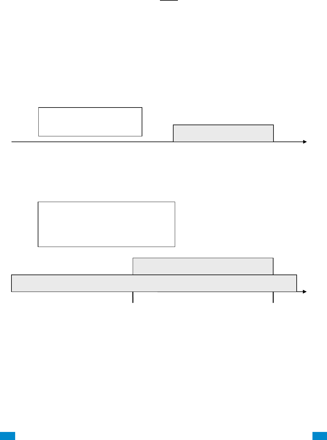
...C... 176 P/N 466-5261 • REV D ISS 17NOV17 UltraSync Modular Hub Reference Manual ©2016 United Technologies Corporation .... .I.....
Permission Schedule 1
The system’s permission schedules determine when to allocate user permissions to a user.
User permissions are numbered from 1 to 4 where permission 1 is the highest priority and
permission 4 is the lowest priority. If user permission 1 schedule is not valid then user
permission 2, 3 and 4 are checked in sequence until a valid schedule can be applied.
Higher priority permissions replace lower priority level permissions when they become
active. Only one permission can be active at any time. Permissions have a logic OR
function.
IMPORTANT: If permission 1 is active due to a valid schedule, permission 2 will never
become active. Make sure to assign/program permissions in the right order.
A cleaner is given access to all areas after hours. They can disarm/arm the security system
from 5pm to 10pm on weekdays. They have no access outside of these times and days.
A bank manager has access to the common areas of the bank 24 hours a day.
During office hours they have access to the bank vault as well. The permissions to access
bank vault become active at 9am, overriding the common areas permission. When the time
becomes 5pm the bank vault permissions become inactive and their lower level permissions
to access the common areas become active again.
IMPORTANT: Only one permission can be active at any one time. User Permission 1
overrides User Permission 2, so ensure User Permission 1 includes all the areas (and other
features) you want to give access to. If User Permission 1 only included the Bank Vault, the
user would NOT have access to the Common Areas.
Bank Manager
User Permission 1 = Bank Vault + Common Areas
Permission Schedule 1 – 9-5 M-F
User Permission 2 = Common Areas
Permission Schedule 1 – 24/7
9am
5pm
User Permission 1: Common + Bank Vault
User Permission 2: Common Areas
5pm
10pm
Cleaner
User Permission 1 = All Areas
Permission Schedule 1 – 5-10pm M-F
User Permission 1: All Areas

...C... 177 P/N 466-5261 • REV D ISS 17NOV17 UltraSync Modular Hub Reference Manual ©2016 United Technologies Corporation .... .I.....
Arm
Only
Standard
Master
Engineer
Master
Engineer
Custom
User
Change their own
PIN code
X
X
X
X
X
Custom
Arm areas
based on permissions
X
X
X
X
X
Custom
Disarm areas
based on permissions
X
X
Limited
X
Custom
Can create and modify
Standard users
X
X
Custom
Program installation
settings
X
X
Custom
Can create and modify
Engineer users
X
Can create custom
permissions and
schedules
X
Area Group
When a non-Custom User Type is selected, this setting determines what areas that user
has access to.
When a Custom User Type is selected, permissions will be used instead of this Area Group
setting.
Start Date
The first date when this user can interact with the system. Future start dates can also be set
here. The user will only be able to interact with the system between the start date and end
date.
End Date
The last date when this user can interact with the system. Future end dates can also be set
here. The user will only be able to interact with the system between the start date and end
date.
Language
Currently English is the only supported language.
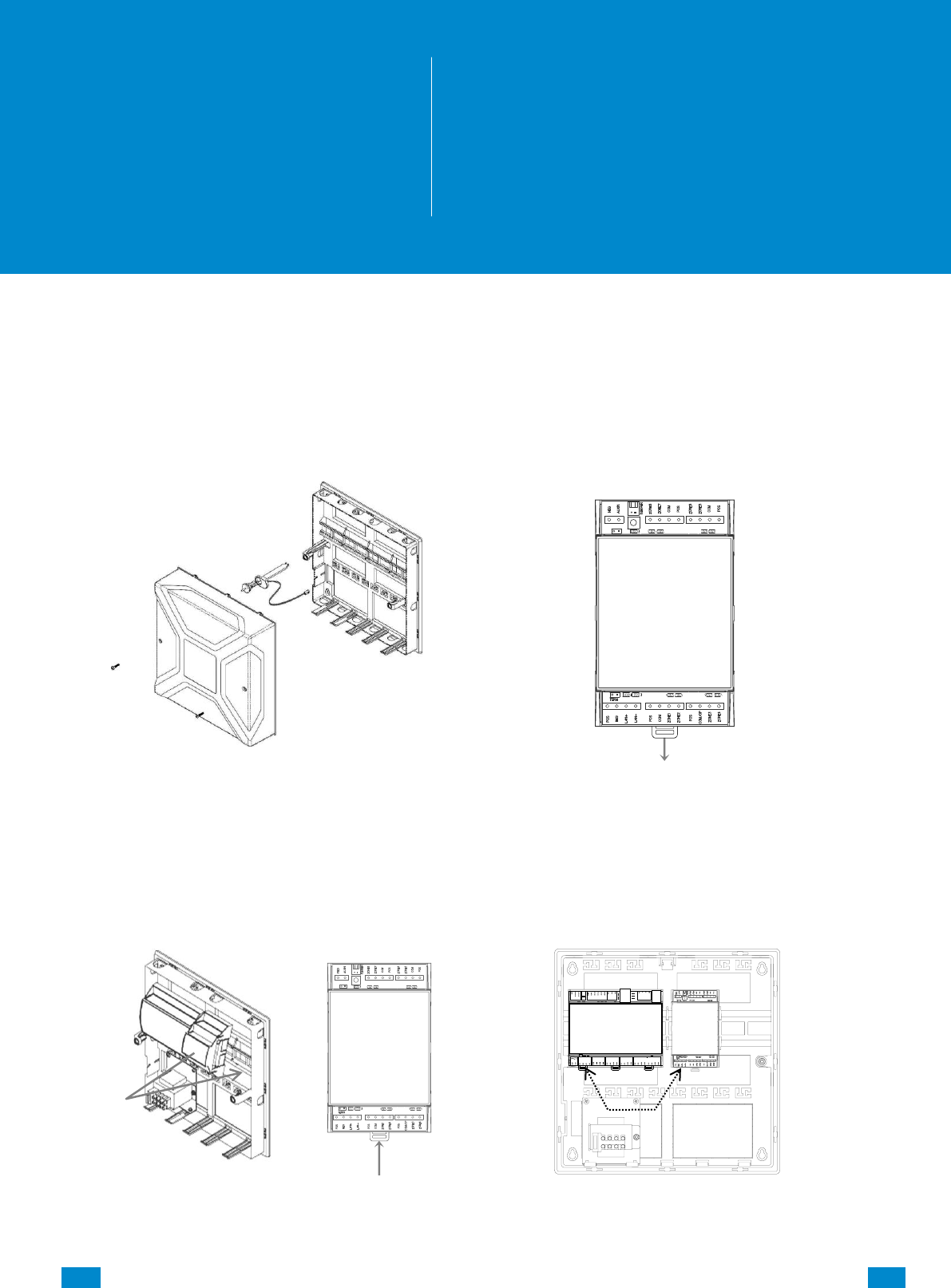
...C... 178 P/N 466-5261 • REV D ISS 17NOV17 UltraSync Modular Hub Reference Manual ©2016 United Technologies Corporation .... .I.....
8 Expansion Module Installation
These instructions are common to Zone or Relay Expansion Modules
1. Open the alarm panel.
2. Pull down the din rail tab on the bottom of
the module. (Pictured: UM-Z8)
3. Hang the module on the top of the din rail,
tilting the bottom of the module outward.
Once the module is vertical, lock the
module on the rail by pushing the tab up.
4. Connect BUS and power off the CPU
8
REFERENCE GUIDE
UltraSync
Modular Hub
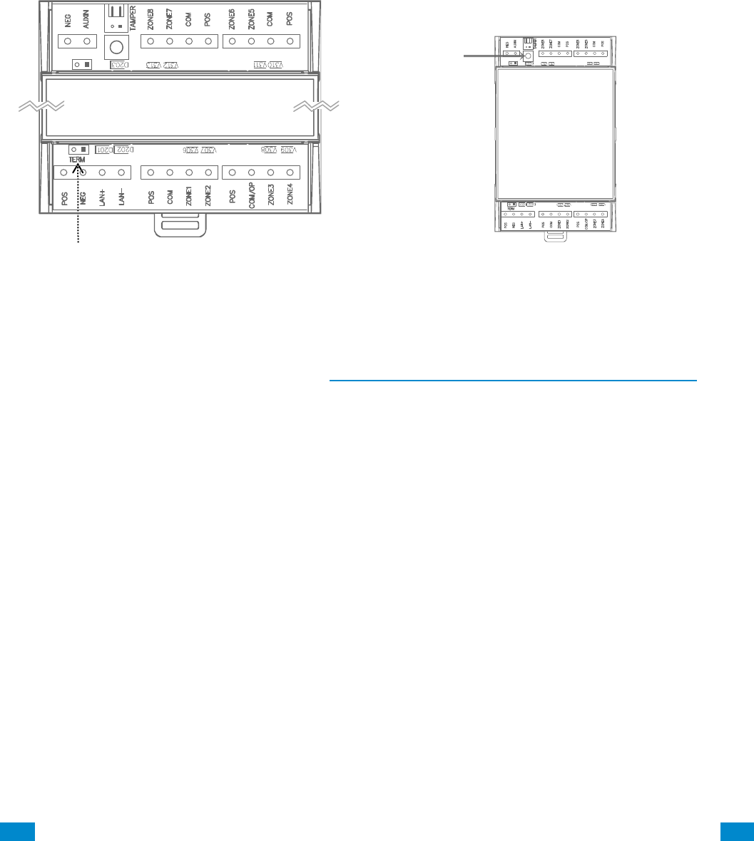
...C... 179 P/N 466-5261 • REV D ISS 17NOV17 UltraSync Modular Hub Reference Manual ©2016 United Technologies Corporation .... .I.....
5. Correct RS-485 termination reduces
communication issues with signal
reflections. For a single long cable run,
put a jumper across the terminal labeled
TERM on the CPU and the furthest bus
device. For installations with multiple
long cable runs, do not place a
terminator on the CPU; rather place one
at the end of each of the two longest
cable runs.
6. Enroll the expansion module in your
system. To manually enroll the module,
use the web interface. In the advanced
menu, navigate to Devices – System
Devices – Control – Enroll Function and
select Manual Enroll from the drop down
menu. This puts the system into the
manual enrollment mode and waits for you
to push the enrollment button on the
expansion module. Hold the button down
for three seconds. (Pictured: UM-Z8)
7. For enrollment options see Section 6.9, Advanced Programming, Devices and Enrollment
8. When connecting powered sensors you can use the zone expansion module’s POS and
COM terminals for power. Powered sensor current draw must be accounted for in your
overall system power budget calculations. Refer to the documentation of the powered
sensor for current draw specifications.
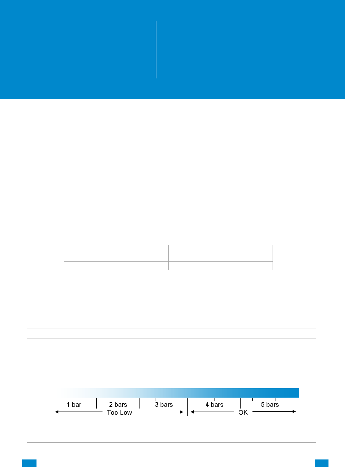
...C... 180 P/N 466-5261 • REV D ISS 17NOV17 UltraSync Modular Hub Reference Manual ©2016 United Technologies Corporation .... .I.....
9 Cellular Radio Setup
An optional cellular radio provides a backup reporting path to the central monitoring station
over a cellular network if the Ethernet connection is not working. This module adds mobile
communication to the alarm panel, allowing alarm reporting and remote connection over the
mobile network via the UltraSync Cloud solution.
This provides a plug and play connection to UltraSync servers for secure reporting with no
configuration needed in most cases. The only requirement is good mobile device reception.
To connect via Cellular Radio you only need to plug in the cellular radio module.
The cellular modem is pre-configured and does not require any programming in the system.
However, the system must be provisioned in the UltraSync Portal for cellular reporting per the
options below:
Connectivity
Portal Provisioning
Ethernet and Cellular
US Grade 2 dual path
Cellular only
US Grade 2 Cellular
Once plugged onto the panel, the unit will automatically register itself on the cellular network.
Please refer the manual that comes with the cellular radio for instructions on how to install it.
9.1 Install Optional Cellular Radio
Note: A SIM card is pre-installed and should not be removed.
A mobile device can provide general guidance on mobile network coverage.
Look at the signal strength on a mobile device to verify there are 4/5 to 5/5 bars of reception
in the location where you will install the system.
If the signal strength is low, find another location which has stronger signal strength.
Note: Actual signal strength can only be determined logging in to the panel.
9
REFERENCE GUIDE
UltraSync
Modular Hub
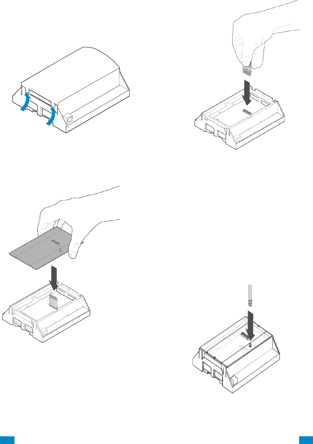
...C... 181 P/N 466-5261 • REV D ISS 17NOV17 UltraSync Modular Hub Reference Manual ©2016 United Technologies Corporation .... .I.....
If a cellular module is pre-installed on the
CPU, skip to the Check Network Coverage
section. If not, remove the cover by releasing
the four (4) side clips with a flat blade
screwdriver.
Locate the 16-pin header on the main
board and insert the board-to-board
connector.
Install the antenna by aligning the
connector and pressing down until you
hear a “click”.
Remove the 3G module from the packaging.
Align the 3G module on the 16-pin header as
shown to the left. Push down until the pins
come through the header. Take care not to
bend the pins.
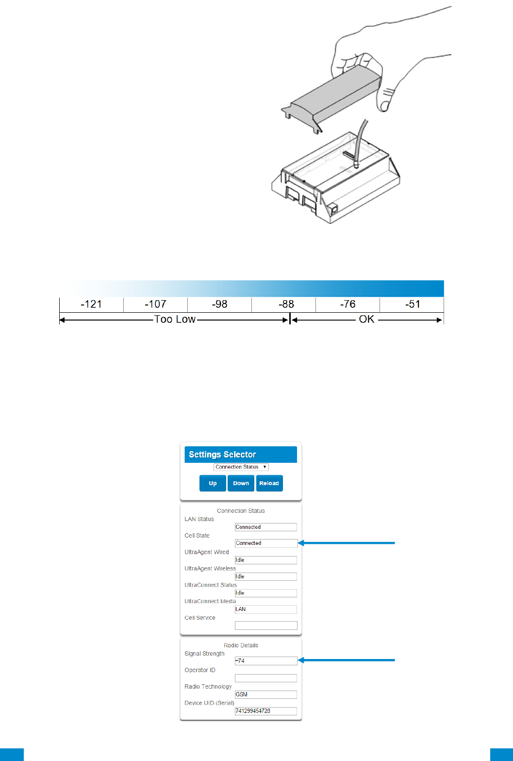
...C... 182 P/N 466-5261 • REV D ISS 17NOV17 UltraSync Modular Hub Reference Manual ©2016 United Technologies Corporation .... .I.....
9.2 Check Signal Strength
This chart illustrates the acceptable signal strength range.
If the reported value is -88 to -51 then the signal strength is OK.
If the reported value is -121 to -89 then relocate the antenna until the signal strength is in
an acceptable range.
To check the signal strength using the UltraSync web server or the UltraSync app:
Login to the UltraSync Web Server, and click Settings – Connection Status.
Scroll down to Signal Strength and check whether Signal Strength is acceptable.
Align the smaller cover included with
the UM-C-H1 and press down until all
four (4) clips lock into place. The
original larger cover is no longer of
use at this stage. For future reference
you may want to peel off the serial
number bar code label from the
original cover and place it on the
smaller cover just installed
Valid Service
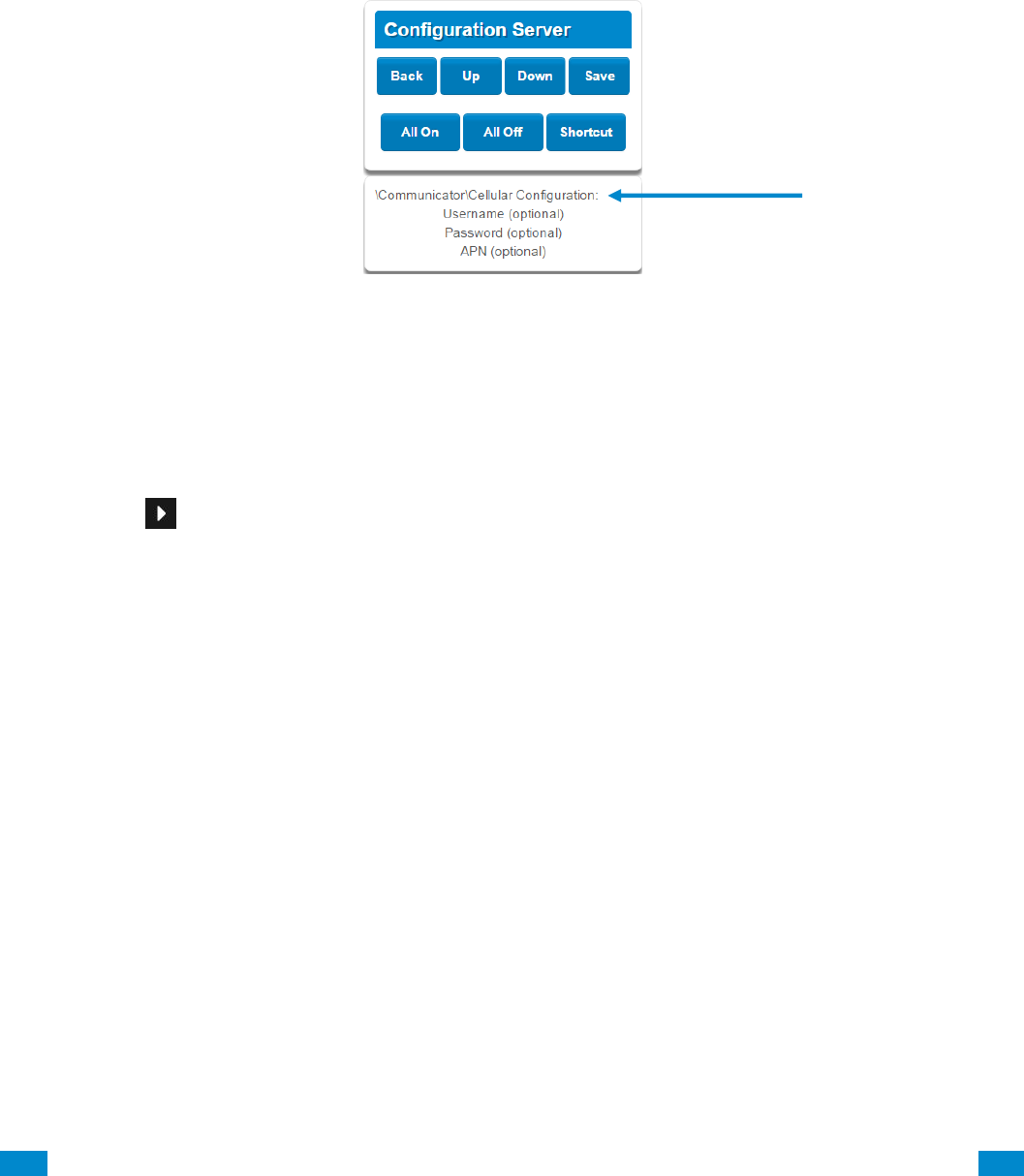
...C... 183 P/N 466-5261 • REV D ISS 17NOV17 UltraSync Modular Hub Reference Manual ©2016 United Technologies Corporation .... .I.....
Check cellular connection:
a. Look at cell state, it should display Connected.
b. Wait until cell state displays Connected, press Reload to refresh the status.
c. Check signal strength – signal strength should be between -88 to -51.
d. Contact Tech Support for assistance.
e. Check that radio is correctly installed and firmly connected.
f. Check if antenna is correctly installed or move antenna to a higher location.
If you need to make changes, open the UltraSync Web Server and go to:
Advanced – Communicator – Cellular configuration:
Only change these settings as instructed by your supplier or telecommunications provider.
To check the signal strength via the UM-1820E keypad:
Press MENU – [PIN code] – Settings – Status – Connection Status.
Scroll Right until you see Signal Strength.
Check whether Signal Strength is acceptable.
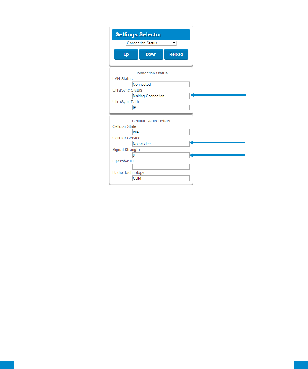
...C... 184 P/N 466-5261 • REV D ISS 17NOV17 UltraSync Modular Hub Reference Manual ©2016 United Technologies Corporation .... .I.....
9.3 Check cellular connection to UltraSync servers
1. Login to the Web Server as shown above.
2. Click Settings.
3. Select Connection Status in the drop down menu.
4. Check:
• UltraSync Status should display “Connected”.
• Cell Service should display “Valid service”.
• Signal Strength should display a value. See Section 9.2 to Check Signal Strength.
If it does not display a signal strength value, check the cellular connection:
1. Check Settings – Network – Enable UltraSync is checked.
Alternatively from a keypad press MENU – Program – Communicator – IP
Configuration – IP Options – Enable UltraSync: Y.
2. Look at Cell State, it should display “Connected”. Please wait until Cell State displays
“Connected”, click Reload to refresh the status.
3. Signal strength should be between -89 to -51.
4. Check cellular radio module is correctly installed.
5. Check cellular radio antenna is correctly installed or move antenna to a new location
with better signal strength.
Congratulations, your system is connected to UltraSync. It is now ready to be
programmed.

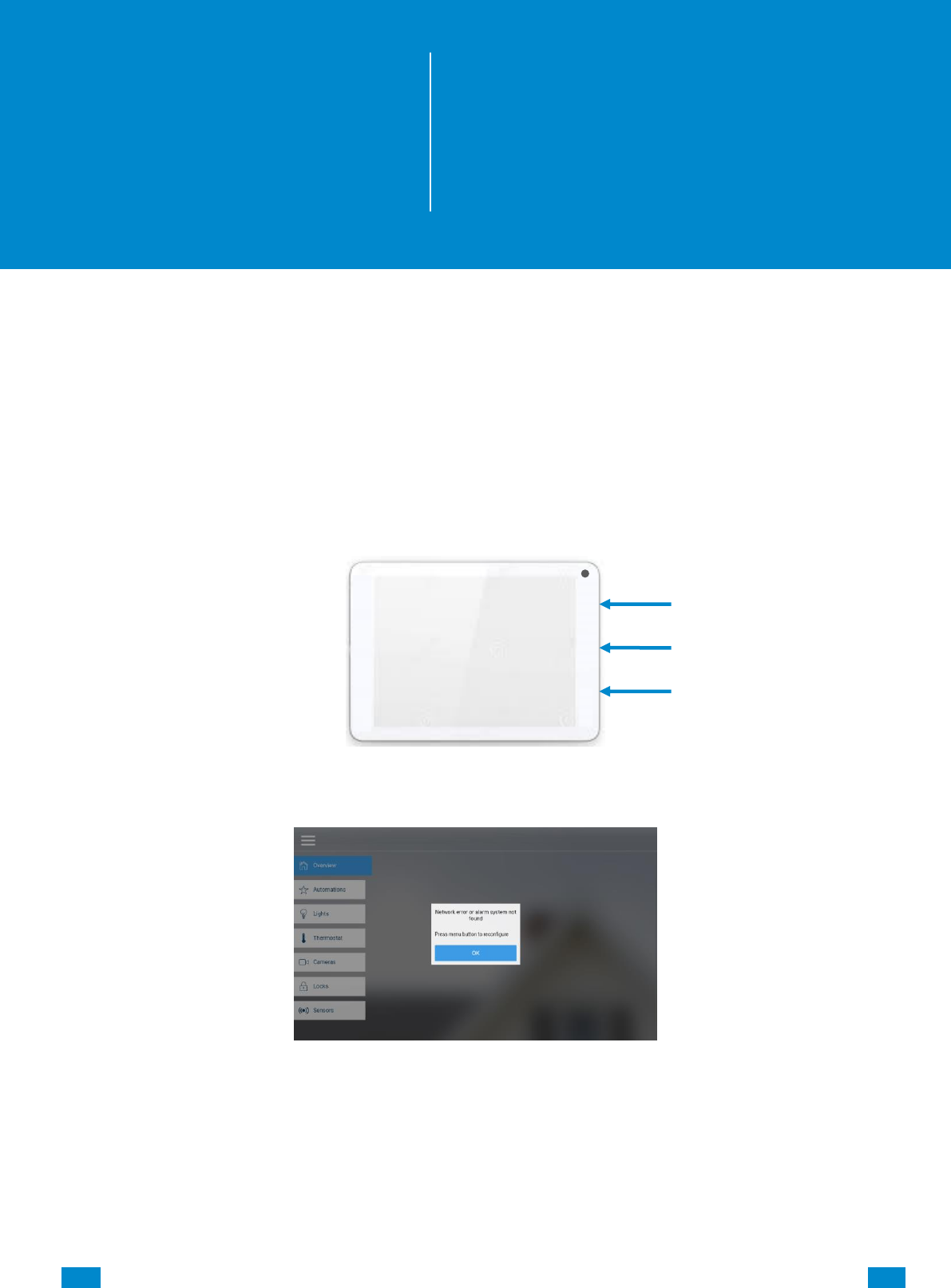
...C... 186 P/N 466-5261 • REV D ISS 17NOV17 UltraSync Modular Hub Reference Manual ©2016 United Technologies Corporation .... .I.....
10 UltraSync Touchscreen Setup
10.1 Quick Setup
1. Connect Power Lead to the touchscreen.
2. Connect the micro-USB connector from power supply to the micro-USB port of the
touchscreen.
3. Power up
Hold the power button on the touchscreen. The screen will light up.
4. On the first startup, you will see a network error message because the touchscreen is not
connected to a Wi Fi network. Press OK. Press the menu button to configure the
touchscreen. The touchscreen will ask you for a PIN.
10
REFERENCE GUIDE
UltraSync
Modular Hub
power
micro USB
volume
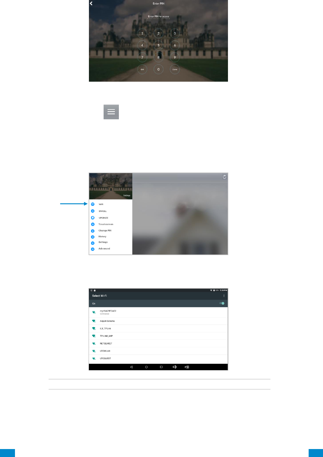
...C... 187 P/N 466-5261 • REV D ISS 17NOV17 UltraSync Modular Hub Reference Manual ©2016 United Technologies Corporation .... .I.....
5. Enter the default installer PIN of the touchscreen, which is 9-7-1-3. Then press Done.
6. Press the settings button.
10.2 Set up Wi Fi
1. Press Wi Fi.
2. Select a Wi Fi network from the list that appears. Press the network you wish to use.
!! Note: The touchscreen and hub must be on the same network. !!
3. Type in the network password and press connect.
4. Once connected to Wi Fi, you will be brought back to the main screen..
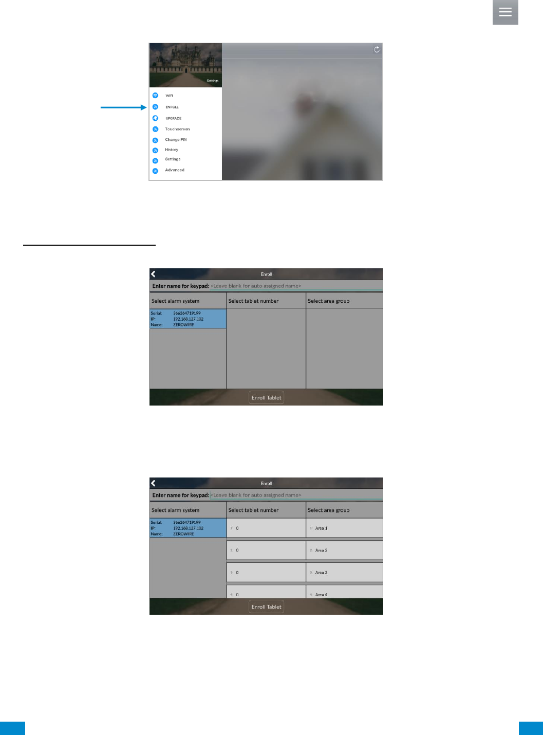
...C... 188 P/N 466-5261 • REV D ISS 17NOV17 UltraSync Modular Hub Reference Manual ©2016 United Technologies Corporation .... .I.....
10.3 Enroll the Touchscreen
1. The touchscreen needs to be enrolled into the UltraSync Hub. Press the menu button
and press enroll.
2. The touchscreen will automatically find any available hubs on the network. They appear in
the left column. Select the desired hub from the network displayed. Enter the installer PIN
that is set up for the hub. Note: This may not be the default 9-7-1-3.
3. Select an available tablet number space (center column). Then select the area group you
wish the touchscreen to control (right column).
4. Press the Enroll Tablet button at the bottom of the screen.
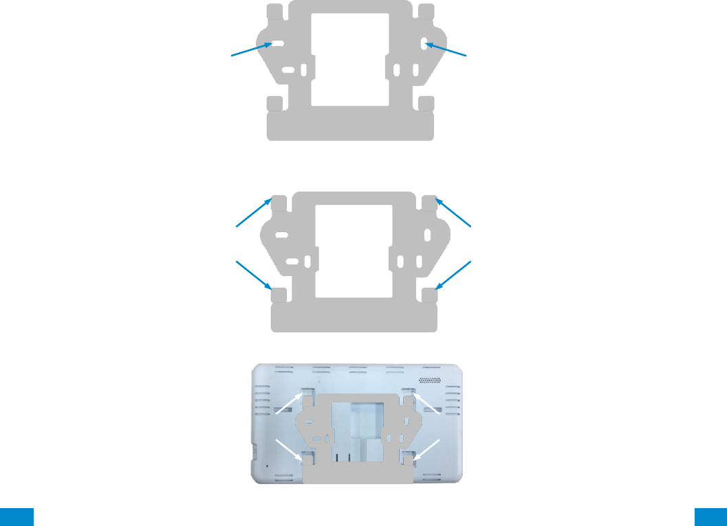
...C... 189 P/N 466-5261 • REV D ISS 17NOV17 UltraSync Modular Hub Reference Manual ©2016 United Technologies Corporation .... .I.....
10.4 Touchscreen Settings
Allow Master User to Upgrade Firmware – Enable this feature to allow the Master User to
have access to the Upgrade menu.
Language – This allows you to select the language the touchscreen displays.
Active Brightness – Choose between 1% - 100%. This is the background light level when
the user is actively using the touchscreen.
Idle Brightness – Choose between 1% - 100%. This is the background light level when the
user is not actively using the touchscreen. Setting the level to 1% will make the touchscreen
appear black when idle. The user may still touch the screen to make the screen active again.
Idle Timeout – Choose between 10 – 300 seconds. This is the amount of time that
touchscreen allows the user to be idle before it locks down and requires a PIN to re-enter the
touchscreen.
Beep Volume – Choose between 1% - 100%. This is the volume level of entry/exit beeps.
Camera User Name and Camera Password – If using the touchscreen with cameras, you
must enter the camera’s User Name and Password to allow access.
10.5 Mounting
1. Mount the wall bracket in the desired location using the supplies wall anchors and screws.
2. Notice the mounting tabs; they slide into slots on the back of the tablet.
Wall Bracket
Mounting holes (3)
Mounting holes (3)
Mounting tabs
Wall Bracket
Mounting tabs
Slide tabs into mounting slots
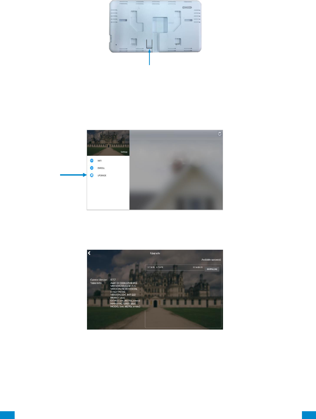
...C... 190 P/N 466-5261 • REV D ISS 17NOV17 UltraSync Modular Hub Reference Manual ©2016 United Technologies Corporation .... .I.....
3. To remove the tablet from the mounting bracket, use a small screwdriver to push up on
the release tab on the bottom of the tablet’s back cover.
10.6 Upgrading Firmware
1. Always upgrade your touchscreen to the latest firmware during the first startup.
2. If firmware is available, press Download. Wait until the download is complete. Press
Install; you will be returned to the main screen
10.7 Other
1. To increase speed and performance, the UltraSync touchscreen communicates with the
cameras using the local network. If you have modified the cameras’ usernames or
passwords you must enter these updated credentials in the touchscreen.
Release tab


...C... 192 P/N 466-5261 • REV D ISS 17NOV17 UltraSync Modular Hub Reference Manual ©2016 United Technologies Corporation .... .I.....
11 Camera Setup Instructions
11.1 Quick Setup
Note: If the light source where the camera is installed experiences rapid, wide variations in
lighting, the camera may not operate as intended.
To quickly put the camera into operation:
1. Prepare the mounting surface.
2 Mount the camera using the appropriate fasteners.
3. Connect the camera to the local network via Ethernet cable or Wi Fi..
4. Learn the camera into the UltraSync App using the “Scan for New Cameras” button
discussed in Section 5.10, Camera Configuration.
11.2 Setting up Ethernet/Wi Fi transmission
Wi Fi transmission distance
The Wi Fi transmission distance/range of the camera is approximately 50 m (164 ft.) in open
air applications.
Note: The transmission distance may vary due to the presence of physical obstacles, such
as trees, walls, elevators, fire doors, furniture, etc. Avoid very solid walls and metallic objects
in the transmission path. Other Wi Fi networks (for example Wi Fi, WiMAX) operating on
2.4 GHz and certain types of devices (e.g., microwave oven point-to-point Wi Fi transmission)
can cause interference with your network. The result would lead to a reduction in
transmission distance/range.
Devices Supported For Ad Hoc Installation
Apple iOS, PC – Windows XP, 7, 8
Devices NOT Supported For Ad Hoc Installation
Android, Windows Mobile, Blackberry
11
REFERENCE GUIDE
UltraSync
Modular Hub

...C... 193 P/N 466-5261 • REV D ISS 17NOV17 UltraSync Modular Hub Reference Manual ©2016 United Technologies Corporation .... .I.....
11.3 Wi Fi Signal Strength
Wi Fi signal strength can be checked in the Network section of the TruVision Browser. Use
the scale below to measure if actions are needed to improve performance.
85+ – Excellent:
No additional actions needed and default video resolutions settings may be increased if
desired.
75-85 – Very Good:
No additional actions needed to increase signal strength. It is not recommended to increase
video resolution settings.
65-75 – Good:
It is recommended to use a Wi Fi repeater or Powerline adapter to increase signal strength.
Alternatively, video resolutions settings may be reduced to minimize poor video quality.
Below 65 – Poor:
It is not recommended to use the camera with a signal strength below 65. Video streams will
likely not work below this level. A Wi Fi repeater or Powerline adapter should be used to
increase signal strength.

...C... 194 P/N 466-5261 • REV D ISS 17NOV17 UltraSync Modular Hub Reference Manual ©2016 United Technologies Corporation .... .I.....
11.4 Add Camera via Wi Fi for iOS Device
1. Power up the camera. (Boot up may take 1-2 minutes)
2. From your iOS device, go to Settings, then Wi Fi.
3. Find and select TVW-xxxxx. (Listed under Devices)
4. Once connected, press the info circle on the right of TVW-xxxxx.
5. Under IP Address, press Static and enter the info below.
a) IP Address 192.168.1.71
b) Subnet Mask 255.255.255.0
6. Open Mobile Browser. (Safari)
7. Enter the camera’s default IP Address into the address bar.
a) 192.168.1.70
8. TruVision Configurator will appear. Enter Credentials below.
a) User Name: admin
b) Password: 1234
9. Press Configuration on the top menu.
10. Press Network on the left menu.
11. Press Wi Fi on the middle tab.
12. Select your network from the Wireless List.
13. Enter Wi Fi Network Passphrase in Key 1 Section.
14. Press Save on the bottom of the screen.
You are now connected to the network via Wi Fi!
11.5 Add Camera via Wi Fi for Windows PC
1. Power up the camera. (Boot up may take 1-2 minutes)
2. From your Windows PC, Find and connect to TVW-xxxxx in Wi Fi network list.
3. Go to Network and Sharing Center.
Control Panel > Network and Internet > Network and Sharing Center
4. Press Change Adapter Settings on left.
5. Right click Wireless Network Connection and select Properties.
6. Click Internet Protocol Version 4 (TCP/IPv4) and click Properties.
7. Click “Use the following IP address”, enter the info below, and then click OK.
a) IP address: 192.168.1.71
b) Subnet mask: 255.255.255.0
8. Open Browser (Firefox, Chrome, IE8) and enter the camera’s IP Address into the
browser’s address bar.
a) Camera’s Default IP Address is 192.168.1.70.
9. TruVision Configurator will appear. Enter Credentials below.
a) User Name: admin
b) Password: 1234
10. Click Configuration on the top menu.
11. Click Network on the left menu.
12. Click Wi Fi on the middle tab.
13. Select your network from the Wireless List.
14. Enter Wi Fi Network Passphrase in Key 1 Section.
15. Click Save on the bottom of the screen.
You are now connected to the network via Wi Fi!

...C... 195 P/N 466-5261 • REV D ISS 17NOV17 UltraSync Modular Hub Reference Manual ©2016 United Technologies Corporation .... .I.....
11.6 Add Camera via Ethernet for iOS Device (non DHCP)
1. Power up the camera. (Boot up may take 1-2 minutes)
2. From your iOS device, go to Settings, then Wi Fi.
3. Find and select TVW-xxxxx. (Listed under Devices)
4. Once connected, press the info circle on the right of TVW-xxxxx.
5. Under IP Address, press Static and enter the info below.
a) IP Address 192.168.1.71
b) Subnet Mask 255.255.255.0
6. Open Mobile Browser. (Safari)
7. Enter the camera’s default IP Address into the address bar.
a) 192.168.1.70
8. TruVision Configurator will appear. Enter Credentials below.
a) User Name: admin
b) Password: 1234
9. Press Configuration on the top menu.
10. Press Network on the left menu.
11. Change LAN settings to desired configuration.
a) Change the IPv4 Address and IPv4 Subnet Mask to match the router if a static IP
Address is desired.
i. You must change the static IP address to something different than the default 192.168.1.70 if
more than one camera is used on the network.
ii. Make sure to use the Test button to validate IP Address is not already assigned to another
device in the network.
12. Press Save on the bottom of the screen.
You are now connected to the network via Ethernet!

...C... 196 P/N 466-5261 • REV D ISS 17NOV17 UltraSync Modular Hub Reference Manual ©2016 United Technologies Corporation .... .I.....
11.7 Add Camera via Ethernet for Windows PC (non DHCP)
1. Power up the camera. (Boot up may take 1-2 minutes)
2. From your Windows PC, Find and connect to TVW-xxxxx in Wi Fi network list.
3. Go to Network and Sharing Center.
Control Panel > Network and Internet > Network and Sharing Center
4. Click Change Adapter Settings on left.
5. Right click Wireless Network Connection and select Properties.
6. Click Internet Protocol Version 4 (TCP/IPv4) and click Properties.
7. Click “Use the following IP address”, enter the info below, and then click OK.
a) IP address: 192.168.1.71
b) Subnet mask: 255.255.255.0
8. Open Browser (Firefox, Chrome, IE8) and enter the camera’s IP Address into the
browser’s address bar.
a) Camera’s Default IP Address is 192.168.1.70.
9. TruVision Configurator will appear. Enter Credentials below.
a) User Name: admin
b) Password: 1234
10. Click Configuration on the top menu.
11. Click Network on the left menu.
12. Change LAN settings to desired configuration.
a) Change the IPv4 Address and IPv4 Subnet Mask to match the router if a static IP
Address is desired.
i. You must change the static IP address to something different than the default 192.168.1.70 if
more than one camera is used on the network.
ii. Make sure to use the Test button to validate IP Address is not already assigned to another
device in the network.
13. Click Save on the bottom of the screen.
You are now connected to the network via Wi Fi!
11.8 Add Camera via Ethernet (DHCP)
1. Power up the camera. (Boot up may take 1-2 minutes)
2. Connect router and camera with Ethernet cable.
You are now connected to the network via Ethernet!
11.9 Add Camera to UltraSync
Ensure proper installation of camera hardware before proceeding to camera setup.
Make sure camera and UltraSecure intrusion panel are on the same local area network.
Applications were the Intrusion panels uses cellular only are not compatible with this camera.
Note: For detailed information on how to setup the UltraSync app, add locations, and login
as an Installer, reference the intrusion panel installation guide.
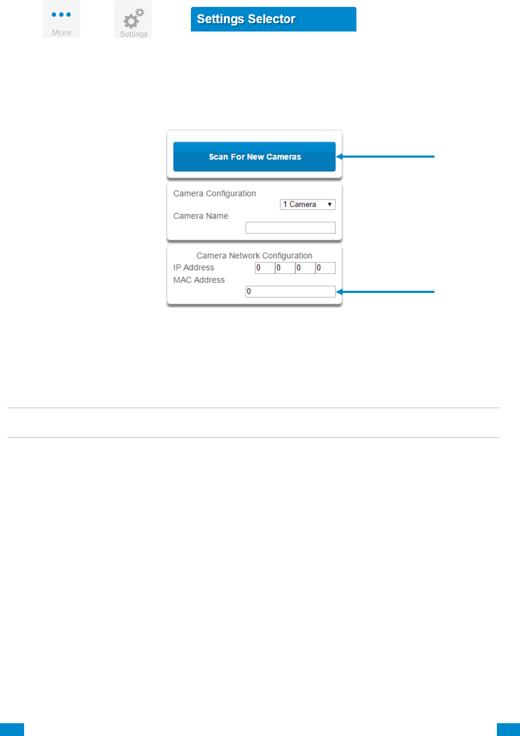
...C... 197 P/N 466-5261 • REV D ISS 17NOV17 UltraSync Modular Hub Reference Manual ©2016 United Technologies Corporation .... .I.....
Press
then
for the
page.
Select Cameras from the drop down menu.
Press Scan for New Cameras. “Success!” message will pop-up after a few moments.
The scan results in an IP address and MAC address listing in the form fields shown.
Make sure the MAC ID that is automatically populated in the MAC Address field matches the
MAC Address printed on the back of the camera. If not, change in the MAC Address to the
one listed on the back of the Camera.
Press Save.
Note: Camera may take up to 1-2 minutes to finalize association with intrusion panel and
show in cameras tab.
CONGRATULATIONS! You have now added the camera to UltraSync!
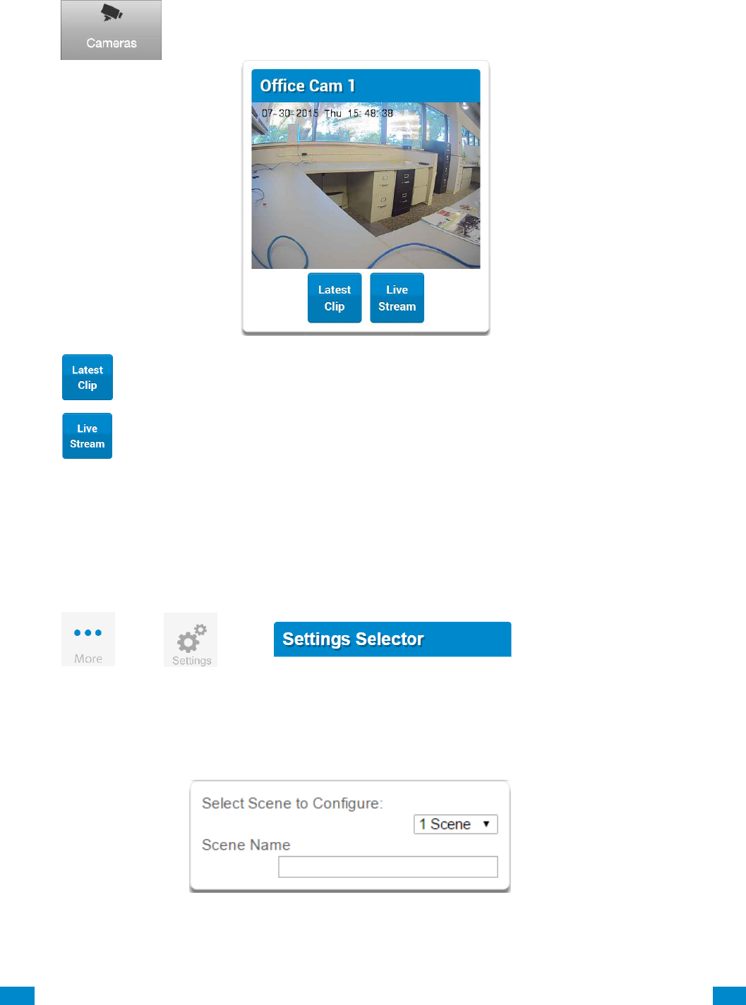
...C... 198 P/N 466-5261 • REV D ISS 17NOV17 UltraSync Modular Hub Reference Manual ©2016 United Technologies Corporation .... .I.....
11.10 View Live Stream and Latest Clip
Press tab on bottom of the screen. All available cameras will be shown.
Press to view a live feed of a specific camera.
Press to view the last recorded clip from a specific camera.
11.11 Program Event Triggered Camera Clips
Cameras can be programmed to automatically record when selected events occur. This is
achieved by creating a scene.
Press
then
for the
page.
Select Automation (Scenes) from the drop down menu.
1. Select the Scene to Configure and type Scene Name.
2. Select the When Should Scene Work drop down menu to restrict when the scene will be
enabled.
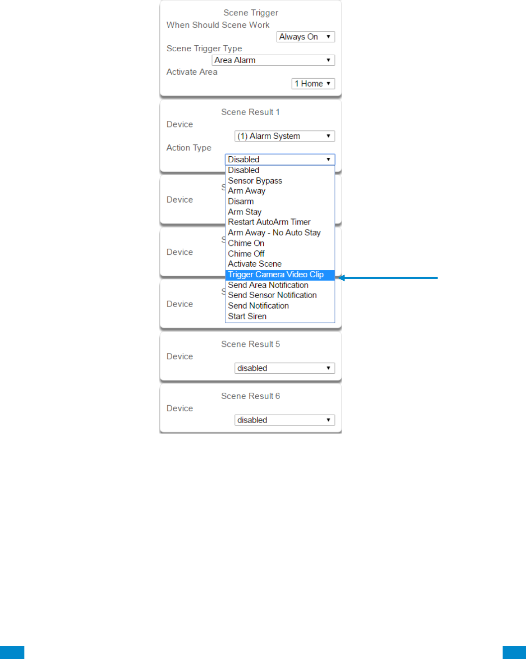
...C... 199 P/N 466-5261 • REV D ISS 17NOV17 UltraSync Modular Hub Reference Manual ©2016 United Technologies Corporation .... .I.....
3. Select the event that will trigger the automation using the Scene Trigger Type drop down
menu. Choices here dynamically change the “Activate” selections.
4. Select Activate ( - - - - ) to assign what that triggers applies to.
5. Select the Scene Result. Choose Alarm System in Device.
6. In Action Type, select Trigger Camera Video Clip
7. Press Save.
Clips are recorded on the Micro SD card installed in the camera and are linked to events in
History.
See the following page to see how to view event triggered clips.
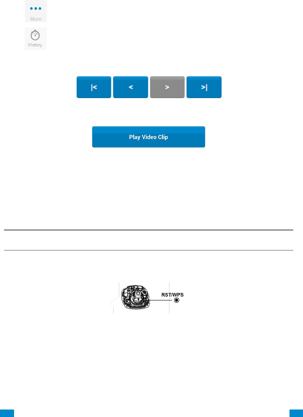
...C... 200 P/N 466-5261 • REV D ISS 17NOV17 UltraSync Modular Hub Reference Manual ©2016 United Technologies Corporation .... .I.....
11.12 View event triggered clips in History
Press on bottom of the screen.
Press
Find the Event you wish to view using Oldest, Prev, Next, and Latest buttons.
Once you find the clip you wish to view, press Play Video Clip.
11.13 Remove Camera from UltraSync (if needed)
1. Press the More tab on the bottom of the Screen.
2. Press Settings.
3. Select Cameras under Settings Selector.
4. Select the camera you with to remove.
5. Delete text in Camera Name, IP Address and MAC Address.
6. Press Save.
Remove All Cameras Shortcut: To remove all cameras from UltraSync, go to Advanced
Settings and use SHORTCUT 910.22.
Reset Camera to Factory Default (if needed)
If needed, the camera can be reset to factory default. Remove the camera cover, then press
and hold the RST/WPS button for 20 Seconds.
11.14 Change Default Camera Settings (Via TruVision Navigator)
1. From a computer or mobile device that is connected on the same network as the camera,
type in the IP address of the camera into the devices browser.
2. Login using default login.
a. Login: admin
b. Password: 1234
3. Change settings as desired such as video quality, frame rate, pre and post recording times.
4. For detailed instructions on using TruVision Navigator, go to www.interlogix.com/video.
...C... 201 P/N 466-5261 • REV D ISS 17NOV17 UltraSync Modular Hub Reference Manual ©2016 United Technologies Corporation .... .I.....
11.15 Camera Troubleshooting
1.
Camera is not showing in list of Wi Fi networks.
Cause
Solution
The camera takes up to 90 seconds to boot up.
It will not show in Wi Fi Networks until this is complete.
The camera has previously been setup and ad hoc
mode was turned off.
Perform a factory reset to broadcast the camera again.
Certain mobile devices do not support ad hoc
mode. iOS and Windows devices are known to
support ad hoc, Android and Windows Mobile
devices typically do not support ad hoc mode.
If your device does not support ad hoc mode, install the
camera using a Windows PC.
2.
The camera does not add to the UltraSync network when I perform the “Scan for Cameras” Function
Cause
Solution
Older firmware versions do not support cameras.
Make sure your panel is updated to the XXXXXX-04
Firmware or new.
The camera will not work if the devices are not on
the same network.
Make sure your camera and system are on the same
network.
The system must be using IP to work with the
cameras.
Make sure your system is not installed using a cellular
radio only.
Make sure you are not adding cameras on a
network that already has a high number of cameras
installed on the same network. This is unusual, but
may be common in testing environments.
Put the system and the cameras on their own router and
this should solve the problem.
3.
The camera was added in the setup process, but the video doesn’t show in the Cameras tab.
Cause
Solution
After completing the setup process, the camera
may take up to 2 minutes to full sync and show in
the UltraSync App.
Wait for the process to complete
Make sure your camera is still connected to the network.
If video still doesn’t show, go back into setup and
perform the “Scan for Cameras” function again.
4.
Live Video isn’t giving good quality. It is choppy, shows gray, etc.
Cause
Solution
Check to make sure your camera’s Wi Fi and/or
Ethernet connection speeds are not poor.
If Wi Fi connection speeds are poor. It is recommended
to use a Wi Fi repeater to increase signal strength.
The cameras default settings are setup to work on a
strong home network.
In some cases, low video settings may be required to
achieve a smooth video. Use the TruVision Browser to
change the cameras video settings.
5.
Video Clips take a long time to load.
Cause
Solution
The cameras default settings are setup to have
video clips start playing in the UltraSync App within
15 seconds (On a strong network). If default
settings were changed to longer clip times or higher
video quality, the amount of time needed to pull the
clip will be higher.
Lower the quality or length of clips to shorten load times.
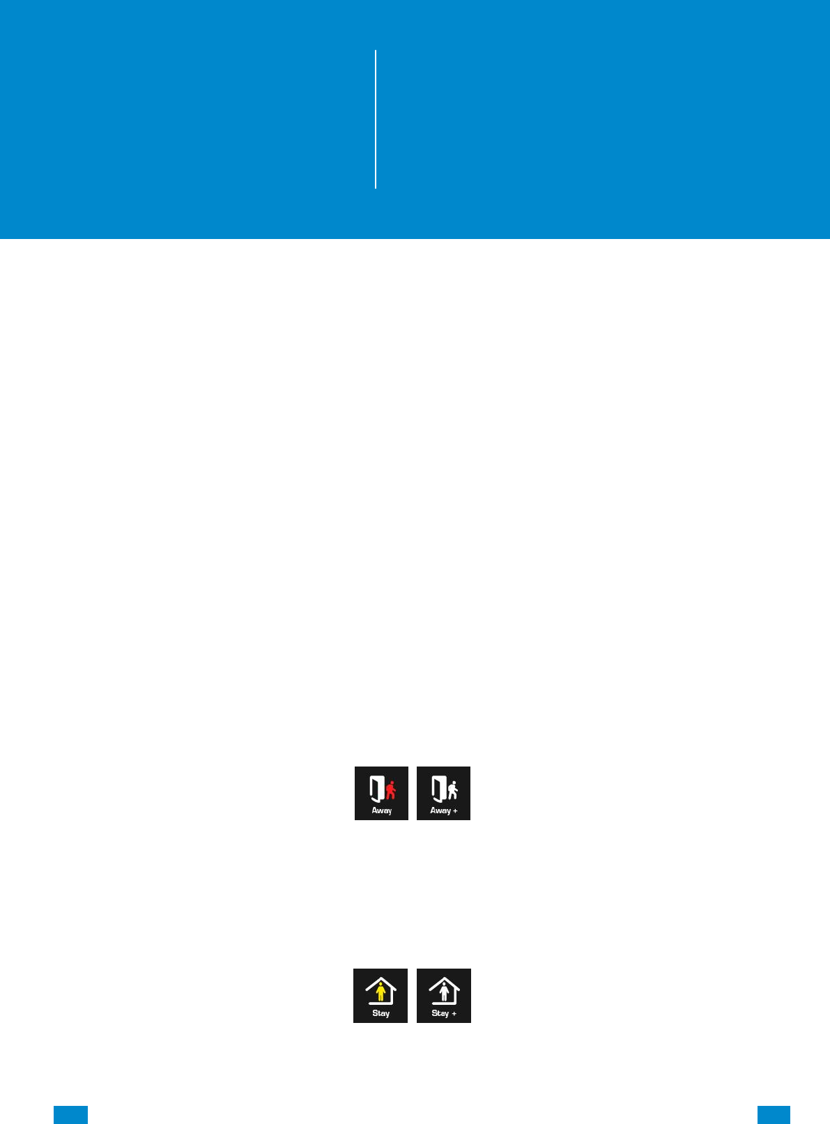
...C... 202 P/N 466-5261 • REV D ISS 17NOV17 UltraSync Modular Hub Reference Manual ©2016 United Technologies Corporation .... .I.....
12 Arming and Disarming the System
Only users with an authorized PIN code (Master/Standard Users) will be allowed to use the
alarm system.
12.1 Keypress Tamper
Disabled by default
When the Enable Idle PIN feature is active, the UM-1820E keypad will be locked in
screensaver mode when unused for a preset time.
A valid PIN is required to unlock the screen and access the system.
When an incorrect PIN is entered 3 times the keypad is locked for 80 +/- 5 seconds and the
screen will display a lock icon. During this time the keypad will not be operational and PIN
codes cannot be entered.
After the 80 +/- 5 seconds expires, if the first PIN attempt is incorrect the 80 +/- 5 second
timer will start again. If the PIN code is valid, then the counter will reset and a further 2
attempts can be accepted.
12.2 Arm Your System in Away Mode
Touch the Away or Away + button to arm your system in Away mode:
If your system has multi-Area control enabled, the Away + button will be displayed.
A valid PIN code will need to be entered to determine what permissions they have, this
includes which Areas and at what time/day that user has access.
12.3 Arm Your System in Stay Mode
Touch the Stay or Stay + button to arm your system in Away mode:
If your system has multi-Area control enabled, the Stay + button will be displayed.
A valid PIN code will need to be entered to determine what permissions they have, this
includes which Areas and at what time/day that user has access.
12
REFERENCE GUIDE
UltraSync
Modular Hub
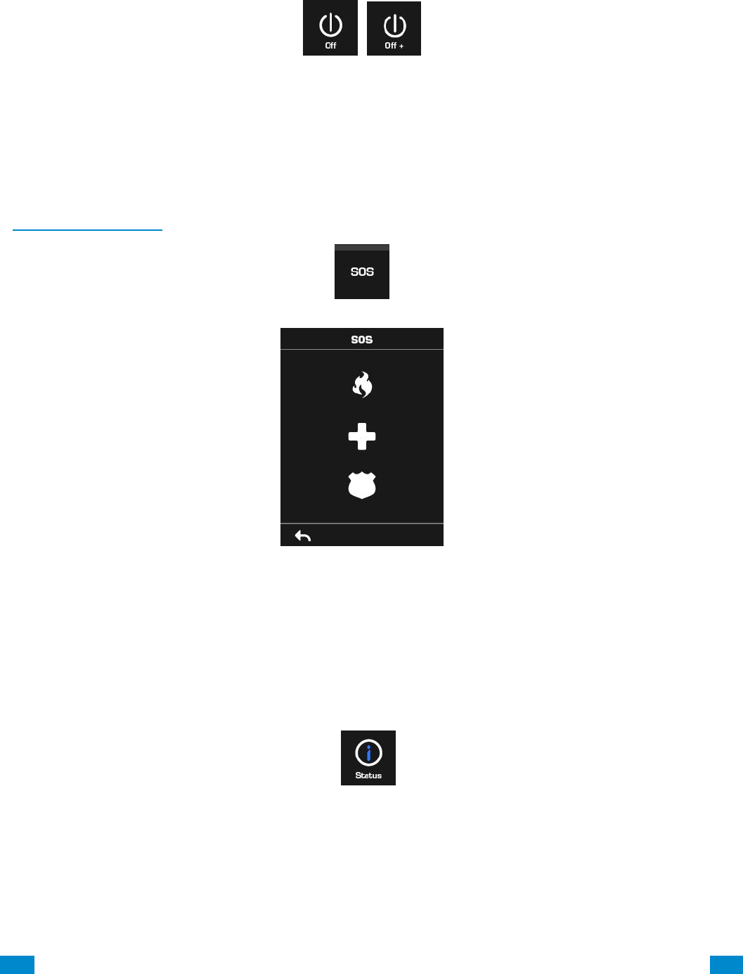
...C... 203 P/N 466-5261 • REV D ISS 17NOV17 UltraSync Modular Hub Reference Manual ©2016 United Technologies Corporation .... .I.....
12.4 Disarm One or More Areas
Touch the Off or Off + button to arm your system in Away mode:
If your system has multi-Area control enabled, the Off + button will be displayed.
A valid PIN code will need to be entered to determine what permissions they have, this
includes which Areas and at what time/day that user has access.
12.5 Activate SOS Feature
SOS functionality is enabled by default. See Areas Programming and the instructions in
Programming Areas. Touch the SOS button to display the SOS feature:
On this screen touch and hold the appropriate button for 2 seconds to activate Manual Fire
Alarm, Manual Auxiliary Alarm, or Manual Panic Alarm.
Depending on how your system is programmed, the control room may receive the
corresponding event. Check with your control room to determine what action will be taken.
If silent alarm is enabled, then the keypad will not display any signs that the panic button was
pressed.
To cancel a SOS alarm – return to the home screen, touch the Status button and turn the
Area off.

...C... 204 P/N 466-5261 • REV D ISS 17NOV17 UltraSync Modular Hub Reference Manual ©2016 United Technologies Corporation .... .I.....
13 Glossary
Action
An action allows the system to perform automation functions. These
can monitor the status up to 4 input conditions called Action Events,
change state (Action State), and perform a function (Action Result)
such as arming a range of areas.
Action Group
An action group is one or more actions that can be accessed by a
device or user. They are assigned to a user or device via
permissions.
Area
Sensors are grouped in to areas which can be secured
independently from each other. This allows you to split your security
system in to smaller components that can be separately managed.
For example your system can be divided into an upstairs area and
downstairs area.
Area Group
An area group is one or more areas that can be accessed by a
device or user. They are assigned to a user or device via
permissions.
Arm
To turn your security system On.
Arm-Disarm
Automatically arm and disarm areas by a specific user according to
a specified schedule. The areas armed and disarmed will be the
ones that the user has access to via their permissions.
Away Mode
To turn your security system on when you are leaving the premises.
Bypass
Sensors can be temporarily disabled so they will not be monitored
by the security system. For example, an interior door is left open,
bypass it to temporarily ignore it and allow arming of the security
system. Bypassed sensors are not capable of activating an alarm.
Sensors will return to normal operation when the system is armed
then disarmed. This prevents unintentional permanent disabling of a
sensor.
Central Station
A company to which alarm signals are sent during an alarm report.
Also known as Central Monitoring Station (CMS).
Channel
A channel is a communication path for events to be sent from the
system to a selected destination. Channels can be set to UltraSync
or Email.
A channel has an associated event list which contains the events it
is allowed to forward on.
Channel Group
A channel group is one or more destinations for event messages to
be sent to. When a message is sent to a channel group, it is sent to
all the channels that it contains. It forms the basis of multi-path
reporting in the system.
Chime Group
All the sensors that will activate chime, when in chime mode.
13
REFERENCE GUIDE
UltraSync
Modular Hub

...C... 205 P/N 466-5261 • REV D ISS 17NOV17 UltraSync Modular Hub Reference Manual ©2016 United Technologies Corporation .... .I.....
Chime Mode
An operational mode that will emit a ding-dong sound at the keypad
when specific sensors are activated.
Closed
A sensor in a normal state is “closed”. The security system monitors
each sensor for changes in state from closed to open and can
respond with certain actions such as sounding the siren.
For example, a reed switch on a front door may change from a
closed state to an open state when the door opens.
Communicator
The communicator is responsible for notifying a control room or third
party that an alarm event has occurred so an appropriate response
can be made.
It sends event messages to the specified destination including
details such as where the event originated from and the type of
event. The receiver will then log the time and date when it receives
the event. For example, Alarm from Sensor 2 in Area 1 at 3:00am
on 5/5/2014 from Account 1234.
The system has multiple communicator options including Ethernet
IP interface, email, and 3G (with optional cellular radio module).
CPU
The main controller for the security system. It stores all
programming, provides network and other connectivity options for
reporting, and provides physical terminals for connecting power,
backup battery, sensors, and outputs.
Disarm
To turn your security system Off.
Duress Code
A predetermined user PIN code that will arm / disarm the security
system while sending a special code to the central monitoring station
indicating the user is entering / leaving the premises under duress.
Only applicable on monitored systems.
Entry Delay
The time allowed to disarm your security system after the first
detection device has been activated.
Event
Events are messages that are sent by the system due to system or
area conditions. These include areas in alarm, opening and closing,
sensor bypass, low battery, tamper, communication trouble, and
power issues.
Event List
Event lists contain events that a channel is allowed to send to the
specified destination. If a channel receives an event that is not in the
associated event list, then the channel will ignore the event.
Exit Delay
The time allowed to exit the premises after the security system is
armed.
Forced Arming
An option that permits arming even when there are open pre-selected
sensors. Generally assigned to sensors that cover the system (e.g.;
motion sensors, front door reed switches), allowing the user to arm
the security system without the need to wait for those sensors to be
closed. A security system that is ready to be “force armed” will flash
the ready light.
Handover
An instant alarm type, unless an entry sensor is tripped first.
Master Code
A PIN code that is used by a user to arm or disarm the security
system. Its main feature is the ability to create, alter and delete user
PIN codes. Can also be used as a function code for all features.
Menus
The system has a large range of features sorted into various menus
such as Users, System, and Sensors. Each menu item can be seen
when using the UltraSync Web Server or the UltraSync app.
Menus are used to restrict what is displayed by a device and what
features a user has access to.
Monitored
A security system that is configured to send all alarm signals to a
central monitoring station.

...C... 206 P/N 466-5261 • REV D ISS 17NOV17 UltraSync Modular Hub Reference Manual ©2016 United Technologies Corporation .... .I.....
Open
A sensor in an abnormal state is “open”. The security system monitors
each sensor for changes in state from closed to open and can
respond with certain actions such as sounding the siren.
For example, when a PIR sensor detects movement it will change
from a closed state to an open state
Output
Outputs on the system can be connected to a siren and strobe when
an alarm condition occurs on the system.
Perimeter
Typically this refers to sensors located around the boundary of the
protected area such as sensors on doors and windows, and excludes
interior motion sensors.
Permission
Permission includes a list of features a user or device is allowed to
access. This includes programming menus, areas, reporting
channels, actions, reporting options, access control options, special
options, and special timers.
Profile
Each user can have up to four (4) permission profiles. Each profile
contains a set of permissions and a corresponding schedule. This
allows advanced user programming and provides specific access to
different features of the security system during specific dates/time.
With advanced programming, profiles can be enabled/disabled in
response to system conditions.
Quick Arm
An option that allows you to turn on (arm) the security system by
pressing the [AWAY] key.
Scene
Each scene can trigger up to 16 actions to create an automation
event. This can save users time by automatically running multiple
actions. A scene can be triggered manually, through a schedule, or
via a system event.
Schedule
A schedule is a list of up to 16 sets of days and times. Typically
these are used to provide access to users only within the specified
sets of days and times. Outside of the schedule a user will not have
access to the system.
Schedules are used to automatically arm and disarm specified
areas using the Arm-Disarm feature.
Scenes can perform a set of actions according to a specified
schedule.
Schedules themselves can be enabled and disabled through
actions. This powerful feature allows you to provide conditional
access to various users and devices based on system conditions.
Sensor
A detection device such as a Passive Infrared motion sensor (PIR),
reed switch, smoke detector, panic button, etc. Sensors may be
physically wired to the system.
Also known as an input or sensor on other security panels.
Service Provider
The installation / maintenance company servicing your security
system.
Stay Mode
To turn your security system on when you are staying in the premises,
this will automatically bypass pre-programmed sensors and arm
others. Often used to arm only the perimeter while allowing movement
inside the premises.

...C... 207 P/N 466-5261 • REV D ISS 17NOV17 UltraSync Modular Hub Reference Manual ©2016 United Technologies Corporation .... .I.....
Tamper
A physical switch on a device that detects unauthorised access to
the unit. For example opening the case of a sensor or taking a
keypad off the wall can trigger a tamper alarm. This can provide
early warning of someone attempting to undermine the security of
your system.
Some devices use an optical sensor to detect removal from a
surface.
Token
Each token is a pre-recorded word or phrase that can be used to
name sensors, areas, outputs, and rooms.
UltraSync
Mobile app for smartphones to access the UltraSync Web Server
which provides access to view the status of a system, control
sensors and outputs, program users and other features. Available to
download for AppleTM iPhoneTM and GoogleTM AndroidTM from the
respective app store.
The UltraSync app connects to the UltraSync server which will then
connect to your system.
UltraSync Web Server
The system has a built-in web server which provides access to
features via a web browser interface or a native smartphone app.
This allows you to performing programming and control of the
system without needing to be physically in front of the keypad.
User
An authorised person who can interact with the system security
system and perform various tasks according to the permissions
assigned to them.
Each user has a set of profile levels. These control what the user
has access to, a list of functions, and when the user is allowed to
perform these functions.
A user is typically a person who is assigned a PIN code and
arms/disarms the system with this code or keyfob device.
Users can also be automatic functions of the system. For example,
the system can automatically arm specific areas a user has access
to at a specified time. No human interaction is required; all the
permissions of the programmed user will still be applied and
enforced.
User Code
A PIN code that is used by a user to arm or disarm the security
system. Also can be used as a function code for certain features.
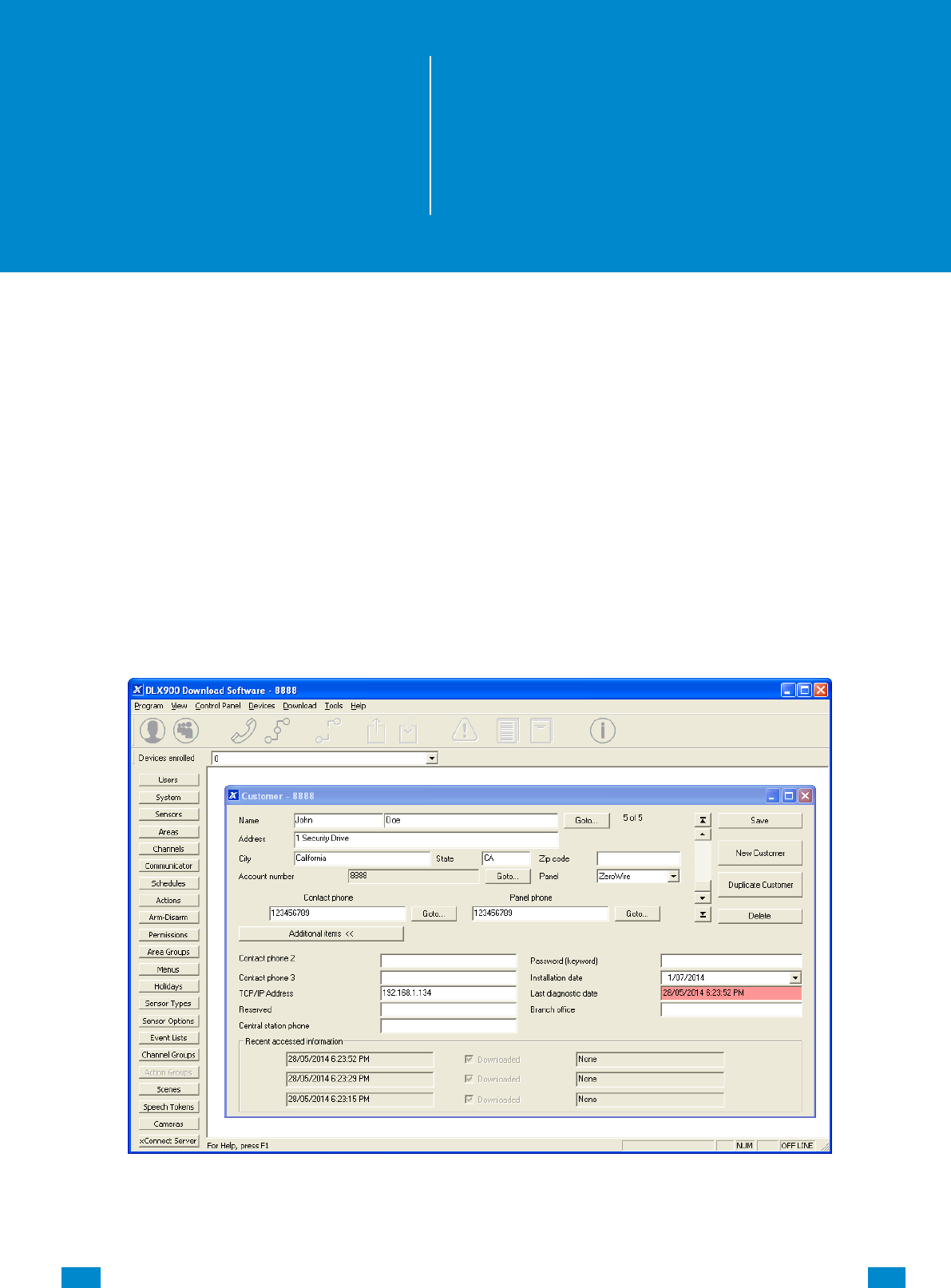
...C... 208 P/N 466-5261 • REV D ISS 17NOV17 UltraSync Modular Hub Reference Manual ©2016 United Technologies Corporation .... .I.....
Appendices
A.1 DLX 900 Software
DLX 900 is a fully featured management tool for control rooms and security professionals.
Compatible with Microsoft Windows 7 and 8, this is available to download from
www.interlogix.com.
In order for DLX 900 to connect to an UltraSync system you will need:
The IP address of the system (or use the Discover feature for LAN connections)
To know the Download Access Code (see Troubleshooting section, A.2) and,
If Always Allow DLX 900 is enabled then you will be allowed to connect; if Always Allow
DLX 900 is disabled then you must first put the UltraSync into program mode, this can be
changed in Settings-Network.
1. Install and launch DLX 900 software.
2. Create a new customer and select the Panel.
A
REFERENCE GUIDE
UltraSync
Modular Hub
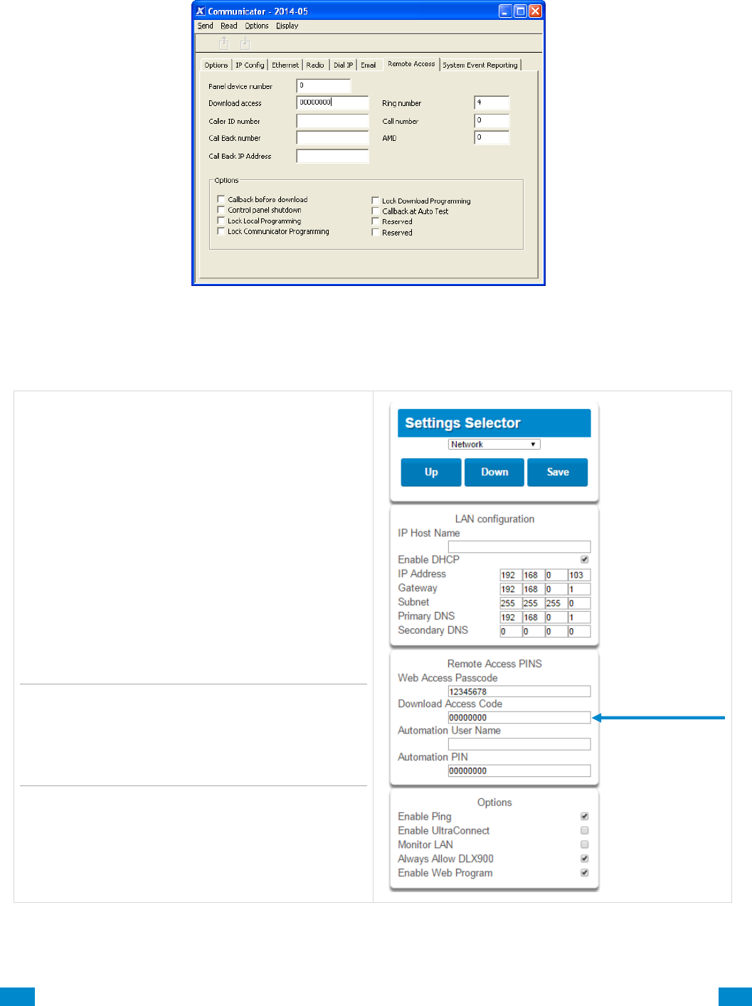
...C... 209 P/N 466-5261 • REV D ISS 17NOV17 UltraSync Modular Hub Reference Manual ©2016 United Technologies Corporation .... .I.....
3. Enter the TCP/IP address of the system, press Save.
4. Go to Communicator – Remote Access.
5. Enter the Download Access Code to match the one configured on the system.
6. Press the Connect TCP/IP button.
To enable remote access for DLX 900 in
UltraSync, change the Download Access
Code. The default Download Access
Passcode of 00000000 prevents remote
access. Login to UltraSync
Web Server and go to Settings – Network
then change the code.
Note: DLX 900 will attempt to connect using
the default installer / 9–7–1–3 account. To
disable DLX 900 access, change the Installer
PIN code and set the Download Access
Code to 00000000.

...C... 210 P/N 466-5261 • REV D ISS 17NOV17 UltraSync Modular Hub Reference Manual ©2016 United Technologies Corporation .... .I.....
A.2 Troubleshooting DLX 900
Problem
Solution
Cannot connect over TCP/IP
Check you can ping the system.
Check the Download Access Code.
Check that remote access is enabled on the system.
You generally need to be on the same network to
connect via TCP/IP. If you are connecting from a
separate network, you will need to set up port
forwarding to port 41796 on the router the system is
connected to. Consult your router manual or your IT
department for assistance. Technical support is
unable to assist with setting up port forwarding due
to differences in customer networks and equipment.
Do not know Download Access Code
Login to UltraSync Web Server and go to Settings –
Network. Generally this will need to be done on-site
with an internet browser.
At factory default, DLX 900 will automatically allow a
connection using the default Go To Program Code /
Installer Code of 9–7–1–3 even if the Download
Access Code is unknown or set to default of
00000000 (disable upload/download). This is a
convenience feature for Installers and control rooms
when a system is first installed.
This is why you must change the Installer Code to
protect the system from further changes. Once the
Installer Code has been changed, this feature no
longer works and you must have the correct
Download Access Code.
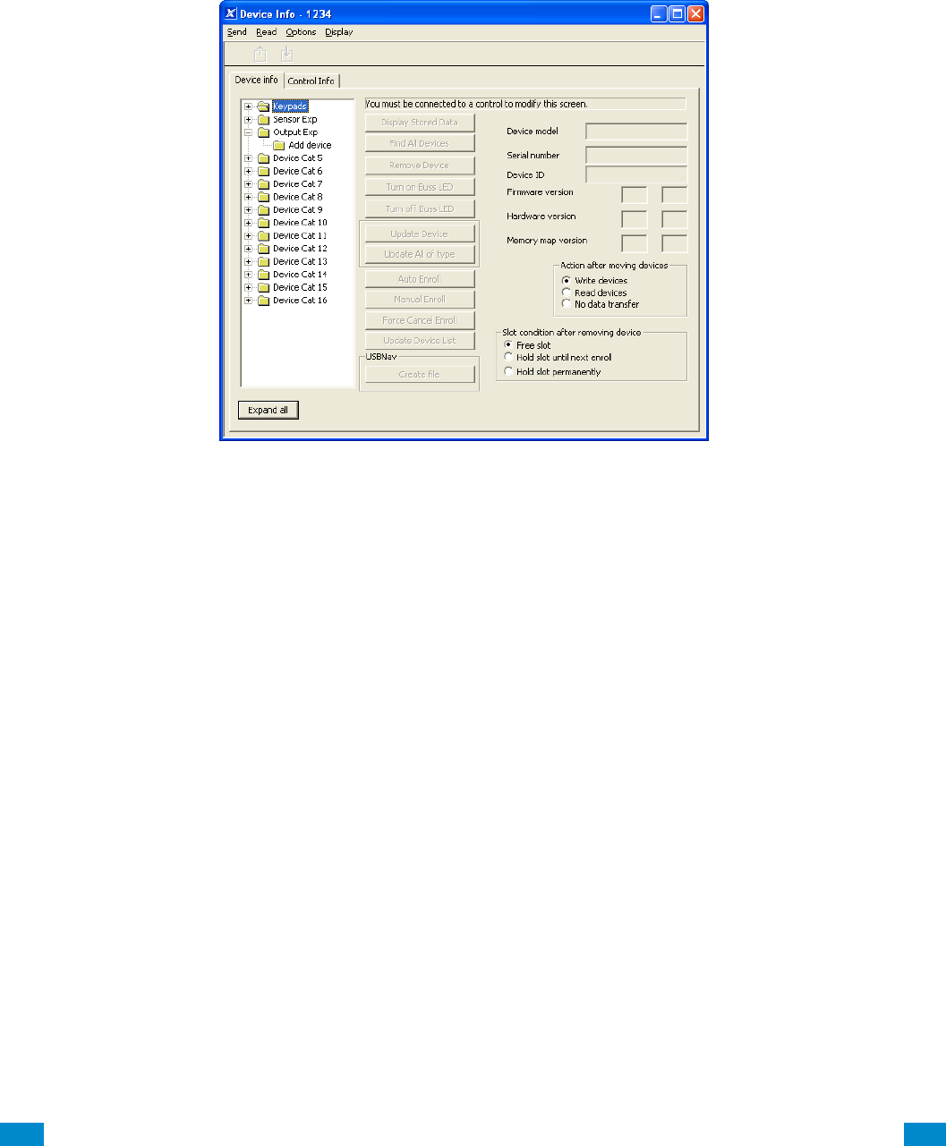
...C... 211 P/N 466-5261 • REV D ISS 17NOV17 UltraSync Modular Hub Reference Manual ©2016 United Technologies Corporation .... .I.....
A.3 Firmware Upgrade using DLX 900
Upgrading firmware can be performed remotely using DLX 900.
1. Check with your supplier to download the latest firmware file for your device.
2. Open DLX 900 and go to Devices – Device Info:
3. Select the device you want to upgrade. If you wish to update the system, select the
Control Info tab.
4. Press Update Device, Update All of Type, or Update Control.
5. Select the firmware file.
6. Press OK.
7. Wait for the firmware files to transfer to your device(s).

...C... 212 P/N 466-5261 • REV D ISS 17NOV17 UltraSync Modular Hub Reference Manual ©2016 United Technologies Corporation .... .I.....
A.4 Voice Library
These words can be used to customize your sensor names.
0
zero
1
one
2
two
3
three
4
four
5
five
6
six
7
seven
8
eight
9
nine
10
ten
11
eleven
12
twelve
13
thirteen
14
fourteen
15
fifteen
16
sixteen
17
seventeen
18
eighteen
19
nineteen
20
twenty
21
thirty
22
forty
23
fifty
24
sixty
25
seventy
26
eighty
27
ninety
28
hundred
29
thousand
30
air conditioner
31
area
32
attic
33
automatic
34
auxiliary
35
back
36
basement
37
bathroom
38
bedroom
39
boat
40
cabinet
41
car park
42
ceiling
43
cellar
44
child’s
45
alert
46
closet
47
computer
48
cool
49
curtain
50
data
51
den
52
detector
53
dining
54
door
55
downstairs
56
driveway
57
duress
58
east
59
emergency
60
entry
61
family
62
fan
63
fence
64
fire
65
forced arm
66
foyer
67
freezer
68
front
69
games
70
garage
71
gas
72
gate
73
glass
74
glass break
75
ground
76
guest
77
gun
78
gym
79
hall
80
hallway
81
heat
82
heating
83
hold-up
84
home
85
home theatre
86
infra-red
87
inside
88
instant
89
interior
90
key switch
91
Keychain
92
kitchen
93
lounge
94
laundry
95
lift
96
light
97
living
98
location
99
master
100
medicine
101
meeting
102
motion
103
night
104
north
105
nursery
106
office
107
output
108
outside
109
panic
110
pantry
111
partial
112
perimeter
113
pool
114
rear
115
reception
116
remote
117
roof
118
room
119
rumpus
120
safe
121
security
122
sensor
123
shed
124
shock
125
shop
126
side
127
skylight
128
sliding
129
small
130
smoke
131
south
132
stairs
133
storage
134
study
135
temperature
136
spare
137
toilet
138
training
139
T V
140
upstairs
141
user
142
utility
143
volt
144
veranda
145
wall
146
warehouse
147
water
148
west
149
window
150
windows
151
wireless
152
yard

...C... 213 P/N 466-5261 • REV D ISS 17NOV17 UltraSync Modular Hub Reference Manual ©2016 United Technologies Corporation .... .I.....
A.5 System Status Messages
Various messages may appear on the Status screen of UltraSync Web Server and UltraSync app.
System
AC power fail – The security system has lost its electricity power.
Low battery – The security system’s back up battery requires charging.
Battery test fail – The security system’s back up battery requires changing.
Box tamper – The security system’s cabinet tamper input has activated.
Siren trouble – The security system’s external siren has a problem.
Over current – The security system is drawing too much current.
Time and date loss – The security system time and date need resetting.
Communication fault – The security system has detected a problem with the
communication channel
Fire alarm – A fire alarm has been activated from the system
Panic – A manual alarm has been activated from the system
Auxiliary – A manual auxiliary alarm has been activated from the system
Area Number / Area Name
Is On in the away mode – This area is armed in the away mode.
Is On in the stay mode – This area is armed in the stay mode.
Is ready – This area is secure and ready to be armed.
Is not ready – This area is NOT ready to be armed, a sensor is not secure.
All areas are on in the away mode – All areas in this multi area system are armed in
the away mode.
All areas are on in the stay mode – All areas in this multi area system are armed in
the stay mode.
All areas are ready – All areas in this multi area system are secure and ready to be
armed.
Sensor Number / Sensor Name
In Alarm – This sensor has triggered a system alarm condition.
Is bypassed – This sensor is isolated (disabled) and will not activate an alarm.
Chime is set – This sensor is part of the chime group.
Is not secure – This sensor is not closed.
Fire alarm – This sensor has triggered a fire alarm.
Tamper – This sensor has triggered a tamper alarm.
Trouble fault – This sensor has an open circuit.
Loss of wireless supervision – This sensor is a wireless device and has lost its
communication link with the control panel.
Low battery – This sensor is a wireless device and needs its battery changed.

...C... 214 P/N 466-5261 • REV D ISS 17NOV17 UltraSync Modular Hub Reference Manual ©2016 United Technologies Corporation .... .I.....
A.6 App and Web Error Messages
Various error messages may appear on the UltraSync Web Server and UltraSync app.
Advanced / Settings Configuration Menus
"You must select a Menu before you can scroll" – An attempt was made to scroll up or
down from the top level menu.
"Select a submenu from the list or select back to access the main menu" – An attempt
was made to scroll up or down from a submenu that has no additional levels.
"Defaulting requires 2 levels" – a Shortcut was entered without two levels.
Read Write errors and results
"Write Access Denied"
"Nothing displayed can be Saved"
"Program Success!"
"Name Saved"
Sensors Page
"No Sensors Configured For Your Access" – Displayed on Sensors page when there
are no sensors available to view.
Data Entry Errors
"Data must only contain the following characters"
"Date must be of the form YYYY–MM–DD."
"Day must be from 1 to 31"
"Data entry must only contain the numbers 0 – 9 and A–F"
"Data entry must only contain the numbers 0 – 9"
"Data must be a number from X to Y"
"Improper Time Value"
"must be 4 to 8 digits
"You must enter a user Number between 1 and 1048575"
"PIN digits must be between 0 and 9"
"PIN Must be 4–8 digits from 0–9"
"Data must not contain the following characters []"

...C... 215 P/N 466-5261 • REV D ISS 17NOV17 UltraSync Modular Hub Reference Manual ©2016 United Technologies Corporation .... .I.....
A.7 Z-Wave Messages
Z-Wave Messages
"Unavailable – Failed Device Function in progress" – An Attempt was made to enter
an add remove mode when failed device mode is active.
"Unavailable – Add mode active" – Attempt was made to enter an add remove mode
when add mode is active.
"Unavailable – Remove mode active" – An Attempt was made to enter an add remove
mode when remove mode is active.
"Unavailable – Resetting Network" – An Attempt was made to enter an add remove
mode when resetting mode is active.
"Unavailable – Backing Up Network" – An Attempt was made to enter an add remove
mode when backup mode is active.
"Unavailable – Restoring Network" – An Attempt was made to enter an add remove
mode when restore mode is active.
"Busy, Try Again Momentarily" – This message is received when the Z-Wave module
is attempting a command and a new command was submitted.
"Not primary controller" – An attempt was made to perform device functions when not
a primary controller.
"Device Not Found in failed list" – An attempt was made to remove a failed device that
is now responding.
"Remove Device failed – already in process" – An Attempt was made to enter remove
mode when remove mode is active.
"Replace Device failed – already in process" – An Attempt was made to enter
Replace mode when Replace mode is active.
"Remove Failed" – An Attempt to remove a device from the network has failed
"Replace Failed" – An Attempt to replace a device from the network has failed
"Function timed out or canceled" Add/Remove/Replace function timed out.
"Unavailable, Try Again Later" – This message is received when the Z-Wave module
is still initializing
"Command Failed" – A Z-Wave command has failed.
"You must press Select to choose a set point" – A set point change was attempted
without selecting a set point to change.
"There are no Failed Devices" – Displayed in the failed device dialog when no failed
devices detected.

...C... 216 P/N 466-5261 • REV D ISS 17NOV17 UltraSync Modular Hub Reference Manual ©2016 United Technologies Corporation .... .I.....
A.8 History Events
The table below lists events that can appear in the event log.
Event ID Table
Event Name
Description
24 Hour Alarm
24 Hour Alarm Restore
Abort
Activity Monitor fail
Alarm Aborted
Alarm was aborted
Automatic Test
Battery Low Event
Battery Low Event Restore
Box Tamper
Box Tamper Restore
Burg Alarm
Burg Alarm Restore
Bypass
Bypass Restore
Cancel
Checksum Fault
Checksum Fault Restore
Clock Changed
Close
Communication Failure
Communication Failure Restore
Cross Zone initial trip
Cross Zone initial trip Restore
Device Enrolled
Device Failure
Device Failure Restore
Door Access
Door Access Denied
Door Forced
Door Forced
Door Propped
Door Propped
Duress
Early Opening
Early Opening
End Listen In
End Local Program
End Remote Program
End Walk Test Mode
End Sensor Test
Exit Error
Expander DC Loss
Expander DC Loss Restore
Expander Low Battery
Expander Low Battery Restore
Fail To Close
Fail to Open
Fire Alarm
Fire Alarm Restore
Fire Maintenance Alarm
Fire Maintenance Alarm Restore

...C... 217 P/N 466-5261 • REV D ISS 17NOV17 UltraSync Modular Hub Reference Manual ©2016 United Technologies Corporation .... .I.....
Fire Supervision
Fire Supervision Restore
First Open
Ground Fault
Ground Fault Restore
Guard Tour Fail
Keypad Lockout
Last Close
Late Closing
Late Opening
Mains Fail Event
Mains Fail Event Restore
Man Down
Manual Audible Panic
Manual Fire
Manual Auxiliary
Manual Silent Panic
Manual Test
Manual Test Restore
Open
Output Activated
Output Deactivated
Over Current
Over Current Restore
Partial Close
Partial Open
Opening from Partial Arm
Power Up
Power Up Restore
Recent Close
Remote Program Fail
Reserved
Reserved Sensor Event Types/Restores
Sensor Low Battery
Sensor Low Battery Restore
Serial Bus Expansion Event
Siren Tamper
Siren Tamper Restore
Start Listen In
Start Local Program
Start Remote Program
Start Walk Test Mode
Start Sensor Test
System Device Bypassed
System Device Un-bypassed
System Shut Down
System Armed
Restore from system shutdown
Tamper
Tamper Restore
Technician Arrival
Technician Left
Telephone Fault
Telephone Fault Restore
Trouble
Trouble Restore
User Activated Output
Valid Code Entered
Valid Code expired
Valid Code lost
Valid Code out of Schedule
Valid Code Void

...C... 218 P/N 466-5261 • REV D ISS 17NOV17 UltraSync Modular Hub Reference Manual ©2016 United Technologies Corporation .... .I.....
Walk Test Fail
Walk Test Pass
Watchdog Reset
Wireless Jam
Wireless Jam Restore
Wireless Supervision
Wireless Supervision Restore
Sensor Activity Supervision
Sensor Activity Supervision Restore
A.9 Event Reporting Class Table
Class Name
Description
Bypass/Bypass Restore
Sensor has been isolated
Cancel
Communication Failures
Don’t care
Used for devices that do not classify events.
Fire Alarm
A fire device created an alarm
Fire Restore
A fire device restored from Alarm
Log Only
Non-Fire Alarm
A non-fire device created an alarm. This includes auxiliary, panic,
and burg.
Non-Fire Restore
A non-fire device restored from alarm.
Open/Close
An area turn on turn off
Power Trouble
Mains and battery trouble
Program Mode
Local or remote programming
Recent Close/Abort
Reserved
Sensor Trouble/restore
Low battery or wireless supervision
System trouble/Restore
A system trouble event or restore.
Tampers/Tamper Restore
A tamper alarm or tamper restore.
Test Reports
Manual or automatic test event
Sensor Trouble/Restore
A fire sensor or day sensor is in trouble or restored from trouble.

...C... 219 P/N 466-5261 • REV D ISS 17NOV17 UltraSync Modular Hub Reference Manual ©2016 United Technologies Corporation .... .I.....
A.10 Action Events: Category and Types
Action Events
Category
Action Event Type
Action Events
Category
Action Event Type
Sensor Events
Disabled
Faulted
Not Faulted
Alarm
Bypass
Tamper
Low Battery
Trouble
Supervision
Chime Enabled
Inhibited (Bypassed)
Alarm Memory
User Events
Disabled
PIN entered
PIN Entered out of schedule
Void PIN Entered
Lost PIN Entered
Expired PIN Entered
Turn On By User
Turn Off By User
Area Events
Disabled
Armed Away
Armed Away + Bypass
Armed Partial
Auto Arm Warning
Holdup Delay
Timed Disarm
Guard Tour Time
Guard Tour Fail
Man Down Timer
Man Down Fail
Entry
Exit 1 or Exit 2
Exit 1
Exit 2
Silent Exit Active
Exit Error
Abort Window
Cancel Window
Sensor Cross Zone Timing
Sensor Bypass
Sensor Tamper
Sensor Not Ready
Sensor Low Battery
Sensor Supervision Fault
Chime On (from sensor)
Walk Test (from sensor)
Trouble (from sensor)
Any Alarm
Burg Alarm
Fire Alarm
Panic Alarm
Auxiliary Alarm
Any Siren
Fire Siren
Non-fire Siren
Keypad Sounder
DLX 900 Turn off command
DLX 900 Turn on partial
DLX 900 Turn on away
Manual Fire
Manual Panic
Manual Auxiliary
User Arm Trigger
User Disarm Trigger
Logic State
Disabled
Action State True
Manual Output On
Manual Output Off
Scene Activated
Action State False
Schedule States
Disabled
Schedule State
Device Status
Disabled
Fire Alarm Verification
Box Tamper
Local Programming
Remote Programming
Battery Test
Off line
Power Up delay
Shut Down
Phone Communicator trouble
Phone Line fault
Ethernet Trouble
Ethernet No Link
Ethernet to Server Fault
Cellular Radio Trouble
Cellular Radio to Server Fault
Event in Reporting Queue
Smoke Power Fail
Mains Fail
Low System Battery
Strobe On
Siren On
Siren Tamper
System Events
Disabled
Remote Program Fail
Watchdog Reset
Room Events
Disabled
Connected To
Pending Connection To
Privacy
Talking
Using Channel 1
Using Channel 2

...C... 220 P/N 466-5261 • REV D ISS 17NOV17 UltraSync Modular Hub Reference Manual ©2016 United Technologies Corporation .... .I.....
A.11 Action Results Category and Action Results Event Types
Action Results
Category
Action Results Event Type
Action Results
Category
Action Results
Event Type
Sensor Results
Sensor Trip Toggle
Sensor Trip
Sensor Restore
Sensor Bypass Toggle
Sensor Bypass
Sensor Unbypass
Sensor Chime Toggle
Sensor Chime On
Sensor Chime Off
User Results
User Expire or
Activate
User Activate
User Deactivate
Area Results
Arm Away
Turn Off
Silence
Arm Stay Toggle
Arm Stay
Arm Away No Auto Stay
Chime Toggle
Chime On
Chime Off
Automatic Sensor Test Toggle
Automatic Sensor Test On
Automatic Sensor Test Off
Auto Arm Timer Restart
Disarm Timer Restart
Man Down Timer Restart
Guard Tour Timer Restart
Hold Up Timer Restart
Activity Timer Restart
Arm or Disarm Test Timer Restart
System Results
Disabled
Detector Reset
Communicator Test
Device Results
Disabled
Battery Test
Start Siren
Device Bypass
Device Unbypass
Camera Results
Camera 1
Camera 2
Camera 3
Camera 4
Camera 5
Camera 6
Camera 7
Camera 8
Camera 9
Camera 10
Camera 11
Camera 12
Camera 13
Camera 14
Camera 15
Camera 16
Scene Results
Scene 1
Scene 2
Scene 3
Scene 4
Scene 5
Scene 6
Scene 7
Scene 8
Scene 9
Scene 10
Scene 11
Scene 12
Scene 13
Scene 14
Scene 15
Scene 16

...C... 221 P/N 466-5261 • REV D ISS 17NOV17 UltraSync Modular Hub Reference Manual ©2016 United Technologies Corporation .... .I.....
A.12 System Building Blocks
On the following page is the system diagram of system showing all the different building
blocks that can be used to create an UltraSync system.
You have full flexibility to customise your system. Program each building block in turn to
complete your system. We suggest left to right, top to bottom. Refine blocks as you go or use
pre-sets to save you time.
The smaller grey blocks indicate related blocks that are used by the larger blue block.
The number on the bottom right of each block indicates the capacity of the system.
...C... 222 P/N 466-5261 • REV D ISS 17NOV17 UltraSync Modular Hub Reference Manual ©2016 United Technologies Corporation .... .I.....
Areas
a) Area Options
b) Area Timers
c) Area Reporting
Sensor Types
- Area Armed
- Area Disarmed
Sensor Options
Event Lists
Area Groups
Channels
Channel Groups
Schedule
Channel Groups
Channel Groups
Holidays
Schedules
Permissions
a) Groups
b) Options/Timers
User
a) Main
b) Advanced
Permissions
Schedules
Menus
Area Groups
Channel Groups
Action Groups
Menus
a) Setup
b) Security…
c) History…
d) Communications
e) Times…
Actions
Holidays
up to
256*
32
32
128
16
16
4
96
128
up tp
256*
up to
512*
up to
96*
Sensor Type
Sensor Options
Area Group
Schedule
User
Communicator
a) General Options
c) IP Config
d) Ethernet
d) Radio
d) Dial IP
d) Email
e) Remote Access
f) System Event Reporting
System
a) System Clock
b) System and Siren
c) Timers
d) Maintenance and Test
Zones
a) Profile 1
b) Profile 2
16
Arm/Disarm
User
Schedule
96
Action Groups
64
Devices Outputs
zone expanders, keypads,
transmitters
Communicator
Event Lists
64
Actions
Channels
Areas
Network Servers
Scenes
16
Actions
Schedules
Speech Tokens
Permissions
Schedules
64

...C... 223 P/N 466-5261 • REV D ISS 17NOV17 UltraSync Modular Hub Reference Manual ©2016 United Technologies Corporation .... .I.....
A.13 System Menu Tree
The menu structure as seen from the Advanced menu in UltraSync Web Server:
910.1 Users
910.2 System
1. System Clock
2. General Options
3. System Timers
4. Siren Options
5. Service and Test Options
6. Status
7. System Counters
8. Language
1. Language
2. Voice language
9. Automation Menu
910.3 Sensors
1. Sensor Number
2. Sensor Name
3. First Sensor Profile
4. Second Sensor Profile
910.4 Areas
1. Area Number
2. Area Name
3. Area Entry-Exit Times
4. Area Options
5. Area Timers
6. Area Type Settings
7. Area Event Reporting
910.5 Reporting and Notifications
1. Channel Number
2. Channel Name
3. Account Number
4. Format
5. Device Number
6. Dest Phone or Email or Push
7. Next Channel
8. Event List
9. Attempts
10. Language
910.6 Communicator
1. General Options
2. Auto Test
3. IP Configuration
1. IP Host Name
2. IP Address
3. Gateway
4. Subnet
5. Primary DNS
6. Secondary DNS
7. Ports
8. Time Server
9. IP Options
4. Cellular Configuration
5. Remote Access
1. Panel Device Number
2. Download Access Code
3. Call Back Number
4. Callback Server
5. Number Of Rings
6. Number of Calls
7. Answering Machine Defeat
8. Download Options
6. System Event Reporting
1. System Channel
2. Attempts
910.7 Schedules
1. Schedule Number
2. Schedule Name
3. Follow Action Number
4. Times and Days
910.8 Actions
1. Action Number
2. Action Name
3. Function
4. Duration Minutes
5. Duration Seconds
6. Event 1
7. Event 2
8. Event 3
9. Event 4
10. Result
910.9 Auto Arm-Disarm
1. Arm-Disarm Number
2. Name
3. User Number
4. Schedule Number
910.10 Devices
1. System Devices
1. Control
2. Keypad
3. Zone Expanders
4. Relay Expanders
5. Power Supplies
2. Interlogix Transmitters
1. Transmitter Number
2. Serial Number
3. User
4. Options
5. Scene
6. Signal Strength
3. Z-Wave Devices
1. Name
2. Basic Type
3. Generic Type
4. Specific Type
910.11 Permissions
1. Permission Number
2. Permission Name
3. Control Groups
4. Permission Options
5. User Timer Options
910.12 Area Groups
1. Area Group Number
2. Area Group Name
3. Area List
910.13 Menus
1. Menu Number
2. Menu Name
3. Menu Selections
910.14 Holidays
1. Holiday Number
2. Holiday Name
3. Date Range
910.15 Sensor Types
1. Sensor Type Number
2. Sensor Type Name
3. Sensor Type Armed
4. Sensor Type Disarmed
910.16 Sensor Options
1. Sensor Options Number
2. Sensor Options Name
3. Sensor Options
4. Sensor Reporting
5. Sensor Contact Options
6. Sensor Report Event
910.17 Event Lists
1. Event List Number
2. Event List Name
3. Event List
910.18 Channel Groups
1. Channel Group Number
2. Channel Group Name
3. Channel
910.19 Action Groups
1. Action Group Number
2. Action Group Name
3. Action Group List
910.20 Scenes
1. Scene Number
2. Scene Name
3. When Should Scene Work
4. Scene Trigger Type
5. Activate Sensor
6. Scene Results
910.21 Speech Tokens
1. Sensor Number
2. Voice Name 1
3. Voice Name 2
4. Voice Name 3
5. Voice Name 4
6. Voice Name 5
7. Voice Name 6
8. Voice Name 7
9. Voice Name 8
910.22 Cameras
1. Camera Number
2. Camera Name
3. LAN IP Address
4. MAC Address
910.23 Network Servers
1. Web Access Passcode
2. Ethernet Server 1
3. Ethernet Server 2
4. Ethernet Server 3
5. Ethernet Server 4
6. Cellular Server 1
7. Cellular Server 2
8. Cellular Server 3
9. Cellular Server 4
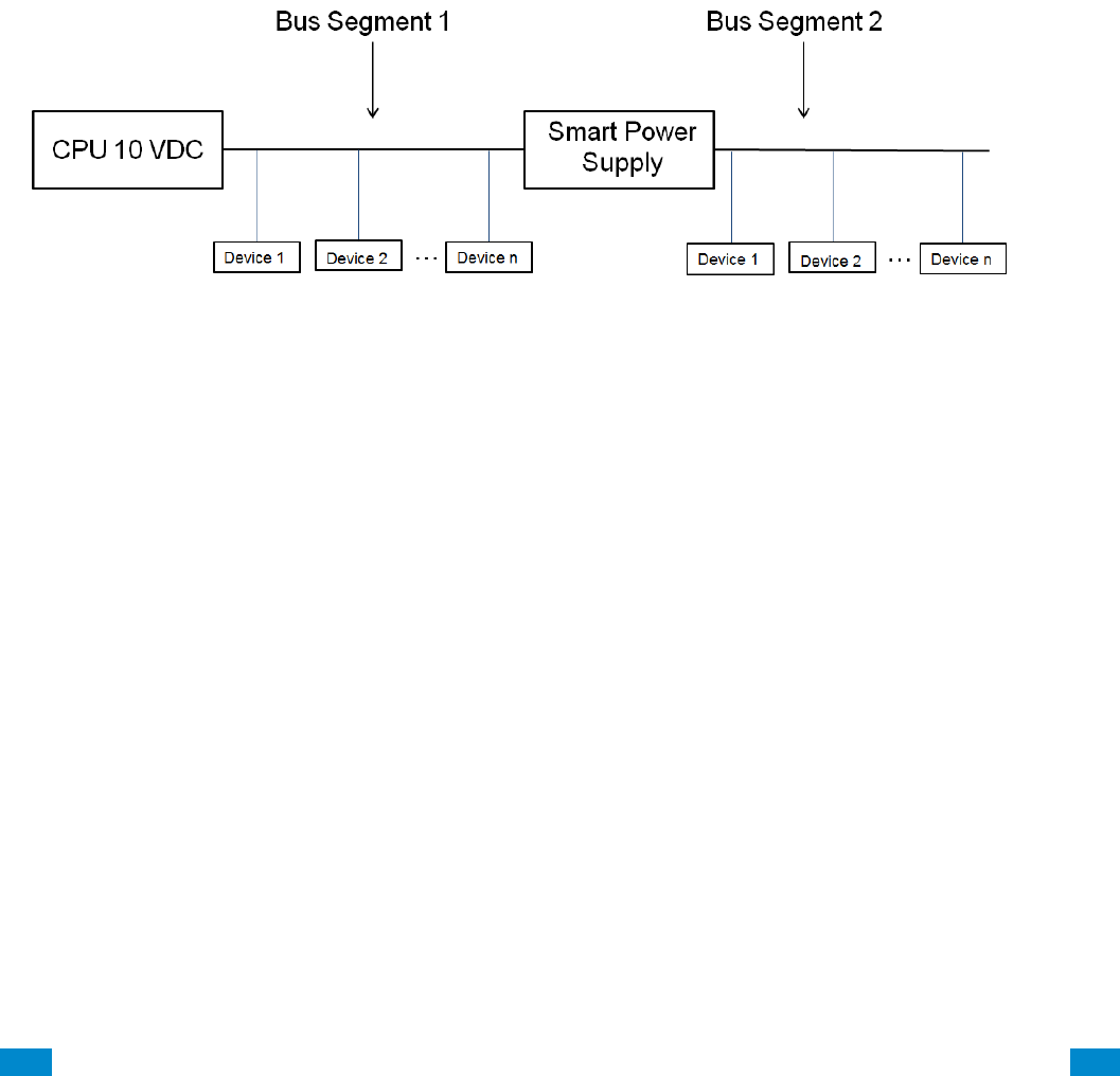
...C... 224 P/N 466-5261 • REV D ISS 17NOV17 UltraSync Modular Hub Reference Manual ©2016 United Technologies Corporation .... .I.....
A.14 Calculating Maximum Bus Cable Length
When long RS-485 bus cable runs and/or many devices are connected on a single cable
segment, voltage losses on the bus wiring may cause the bus voltage to drop below the
required level to power the connected devices.
Factors contributing to voltage drop:
1. The more devices that are connected on the cable segment, the higher the current and
hence, the higher the voltage drop
2. The longer the cable run, the higher the voltage drop
3. A lower gauge wire will have more voltage drop than a higher gauge wire
If these factors drop the bus voltage below the minimum voltage required to power the
connected devices (device shutdown voltage), a UM-SPS Smart Power Supply must be
inserted in the cable segment such that the bus voltage remains above the device shutdown
voltage.
When designing the power system, you must design it for the worst case scenario. That is, 1)
when AC power is lost and the system is operating off of battery power and 2) for the alarm
or maximum current of the connected devices.
When AC power is lost and the system is operating off of battery power, the system will shut
down when the CPU output voltage drops below 10 VDC. Thus, the voltage drop from 10
VDC must be used to determine the bus voltage given the total current on that section of bus
wiring AND the gauge of the wiring used.
1. Add up the maximum current on the bus segment
2. Determine the highest shut down voltage for all devices on the bus segment
3. Use the appropriate chart below for the AWG of the cable for this segment to determine
the maximum cable length
4. If the actual bus segment length exceeds the maximum cable length in the chart, you will
need to break up the segment with a UM-SPS Smart Power Supply.
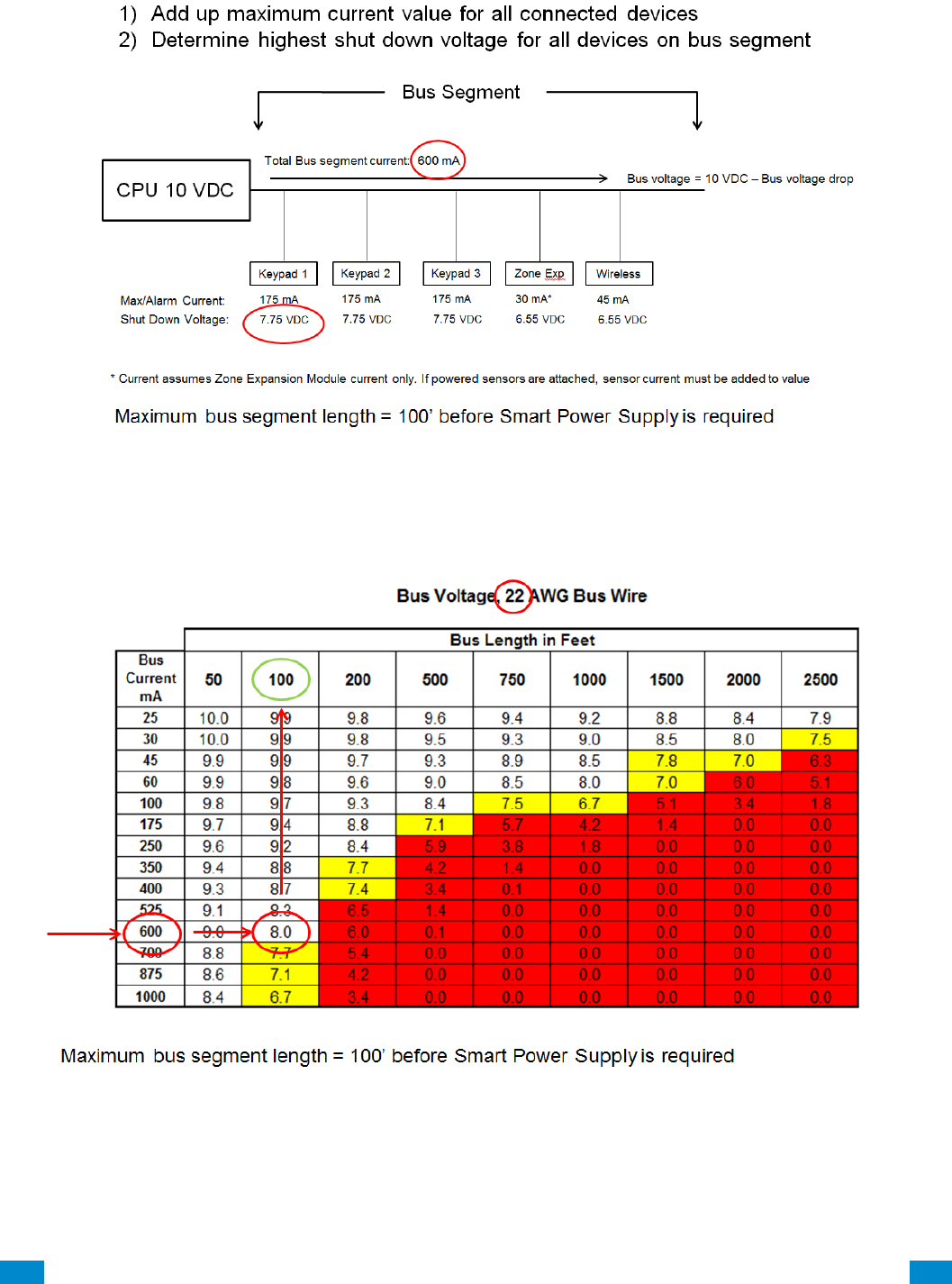
...C... 225 P/N 466-5261 • REV D ISS 17NOV17 UltraSync Modular Hub Reference Manual ©2016 United Technologies Corporation .... .I.....
Example calculation of total bus segment current:
Total Bus segment current: 600mA
Worst Case device shut-down voltage: 7.75 VDC (keypad)
22 AWG wire
For example, if the bus length is 200 feet, the corresponding bus voltage will be 6 VDC which
is less than the shutdown voltage of the UM-1820E Touch Screen Keypads (7.75 VDC). In
this instance, a UM-SPS Smart Power Supply would need to be inserted in the bus at the
100’ location.
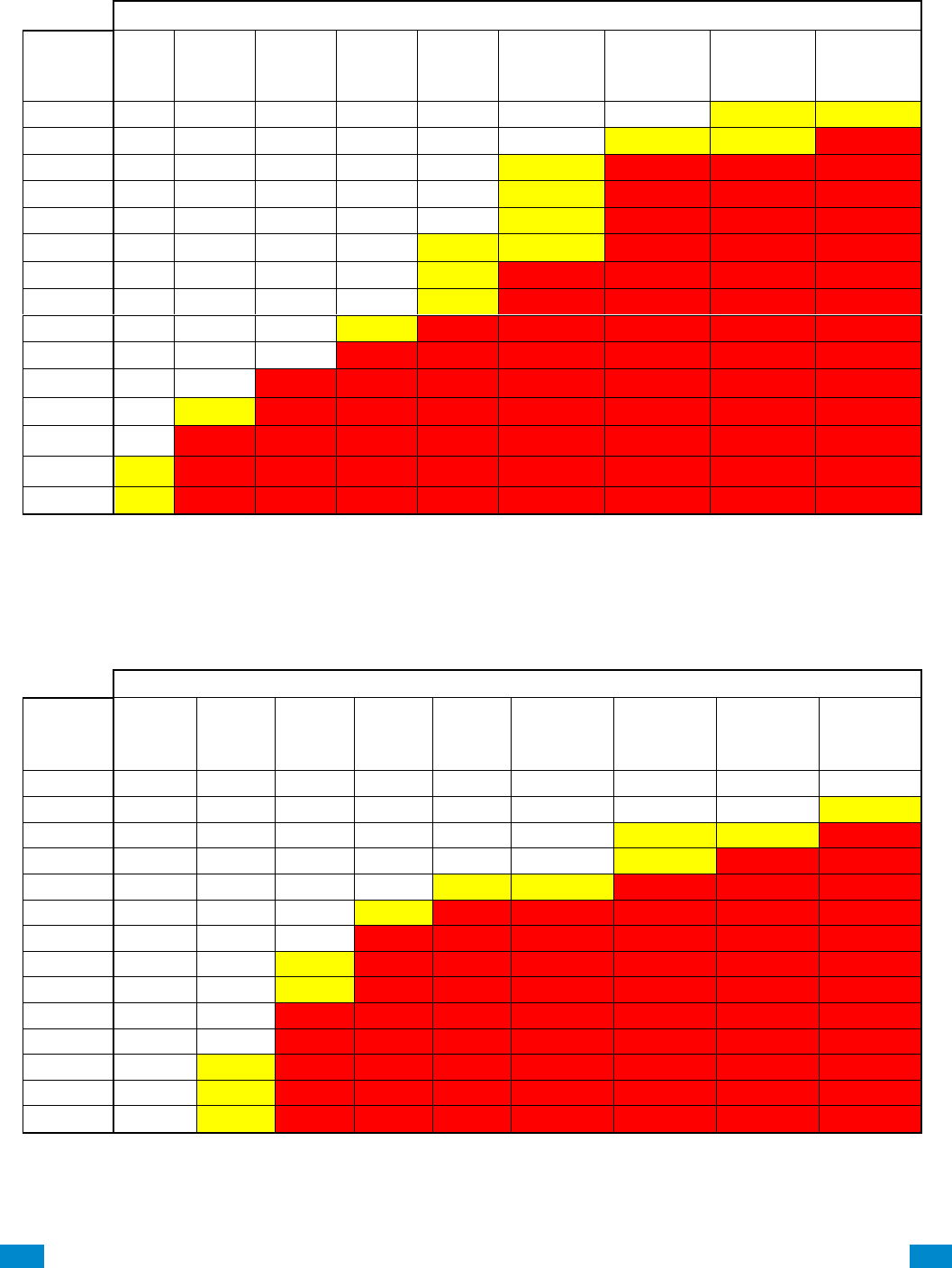
...C... 226 P/N 466-5261 • REV D ISS 17NOV17 UltraSync Modular Hub Reference Manual ©2016 United Technologies Corporation .... .I.....
Bus Voltage, 24 AWG Bus Wire
Bus Length in Feet
Bus
Current
mA
50
100
200
500
750
1000
1500
2000
2500
25
9.9
9.9
9.7
9.3
9.0
8.7
8.0
7.4
6.7
30
9.9
9.8
9.7
9.2
8.8
8.4
7.6
6.9
6.1
45
9.9
9.8
9.5
8.8
8.2
7.6
6.5
5.3
4.1
50
9.9
9.7
9.5
8.7
8.0
7.4
6.1
4.8
3.5
55
9.9
9.7
9.4
8.6
7.8
7.1
5.7
4.2
2.8
60
9.8
9.7
9.4
8.4
7.6
6.9
5.3
3.7
2.1
70
9.8
9.6
9.3
8.2
7.3
6.3
4.5
2.7
0.8
80
9.8
9.6
9.2
7.9
6.9
5.8
3.7
1.6
0.0
90
9.8
9.5
9.1
7.6
6.5
5.3
2.9
0.6
0.0
175
9.5
9.1
8.2
5.4
3.1
0.8
0.0
0.0
0.0
350
9.1
8.2
6.3
0.8
0.0
0.0
0.0
0.0
0.0
525
8.6
7.3
4.5
0.0
0.0
0.0
0.0
0.0
0.0
700
8.2
6.3
2.7
0.0
0.0
0.0
0.0
0.0
0.0
875
7.7
5.4
0.8
0.0
0.0
0.0
0.0
0.0
0.0
1000
7.4
4.8
0.0
0.0
0.0
0.0
0.0
0.0
0.0
Bus Voltage, 22 AWG Bus Wire
Bus Length in Feet
Bus
Current
mA
50
100
200
500
750
1000
1500
2000
2500
25
10.0
9.9
9.8
9.6
9.4
9.2
8.8
8.4
7.9
30
10.0
9.9
9.8
9.5
9.3
9.0
8.5
8.0
7.5
45
9.9
9.9
9.7
9.3
8.9
8.5
7.8
7.0
6.3
60
9.9
9.8
9.6
9.0
8.5
8.0
7.0
6.0
5.1
100
9.8
9.7
9.3
8.4
7.5
6.7
5.1
3.4
1.8
175
9.7
9.4
8.8
7.1
5.7
4.2
1.4
0.0
0.0
250
9.6
9.2
8.4
5.9
3.8
1.8
0.0
0.0
0.0
350
9.4
8.8
7.7
4.2
1.4
0.0
0.0
0.0
0.0
400
9.3
8.7
7.4
3.4
0.1
0.0
0.0
0.0
0.0
525
9.1
8.3
6.5
1.4
0.0
0.0
0.0
0.0
0.0
600
9.0
8.0
6.0
0.1
0.0
0.0
0.0
0.0
0.0
700
8.8
7.7
5.4
0.0
0.0
0.0
0.0
0.0
0.0
875
8.6
7.1
4.2
0.0
0.0
0.0
0.0
0.0
0.0
1000
8.4
6.7
3.4
0.0
0.0
0.0
0.0
0.0
0.0
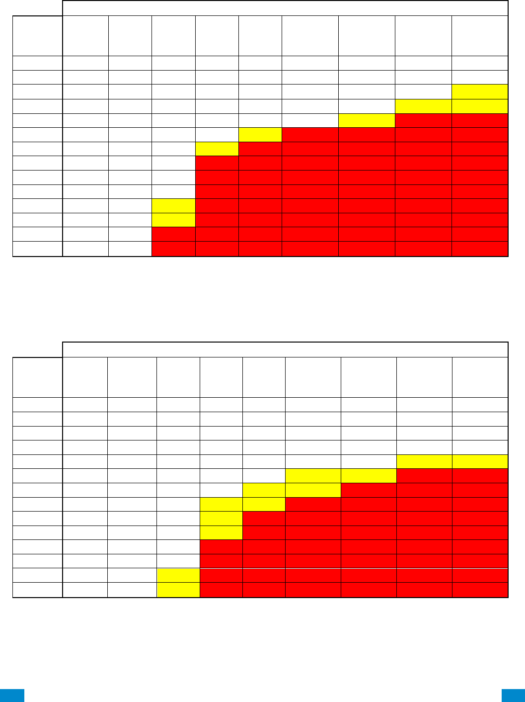
...C... 227 P/N 466-5261 • REV D ISS 17NOV17 UltraSync Modular Hub Reference Manual ©2016 United Technologies Corporation .... .I.....
Bus Voltage, 20 AWG Bus Wire
Bus Length in Feet
Bus
Current
mA
50
100
200
500
750
1000
1500
2000
2500
25
10.0
9.9
9.9
9.7
9.6
9.5
9.2
9.0
8.7
30
10.0
9.9
9.9
9.7
9.5
9.4
9.1
8.8
8.4
45
10.0
9.9
9.8
9.5
9.3
9.1
8.6
8.1
7.7
60
9.9
9.9
9.8
9.4
9.1
8.8
8.1
7.5
6.9
100
9.9
9.8
9.6
9.0
8.4
7.9
6.9
5.9
4.8
175
9.8
9.6
9.3
8.2
7.3
6.4
4.6
2.7
0.9
250
9.7
9.5
9.0
7.4
6.1
4.8
2.2
0.0
0.0
350
9.6
9.3
8.5
6.4
4.6
2.7
0.0
0.0
0.0
400
9.6
9.2
8.3
5.9
3.8
1.7
0.0
0.0
0.0
525
9.5
8.9
7.8
4.6
1.8
0.0
0.0
0.0
0.0
600
9.4
8.8
7.5
3.8
0.7
0.0
0.0
0.0
0.0
700
9.3
8.5
7.1
2.7
0.0
0.0
0.0
0.0
0.0
875
9.1
8.2
6.4
0.9
0.0
0.0
0.0
0.0
0.0
1000
9.0
7.9
5.9
0.0
0.0
0.0
0.0
0.0
0.0
Bus Voltage, 18 AWG Bus Wire
Bus Length in Feet
Bus
Current
mA
50
100
200
500
750
1000
1500
2000
2500
25
10.0
10.0
9.9
9.8
9.8
9.7
9.5
9.3
9.2
30
10.0
10.0
9.9
9.8
9.7
9.6
9.4
9.2
9.0
45
10.0
9.9
9.9
9.7
9.6
9.4
9.1
8.8
8.5
60
10.0
9.9
9.8
9.6
9.4
9.2
8.8
8.4
8.0
100
9.9
9.9
9.7
9.3
9.0
8.7
8.0
7.4
6.7
175
9.9
9.8
9.5
8.9
8.3
7.7
6.6
5.4
4.3
250
9.8
9.7
9.3
8.4
7.6
6.7
5.1
3.5
1.8
350
9.8
9.5
9.1
7.7
6.6
5.4
3.2
0.9
0.0
400
9.7
9.5
9.0
7.4
6.1
4.8
2.2
0.0
0.0
525
9.7
9.3
8.6
6.6
4.9
3.2
0.0
0.0
0.0
600
9.6
9.2
8.4
6.1
4.1
2.2
0.0
0.0
0.0
700
9.5
9.1
8.2
5.4
3.2
0.9
0.0
0.0
0.0
875
9.4
8.9
7.7
4.3
1.4
0.0
0.0
0.0
0.0
1000
9.3
8.7
7.4
3.5
0.2
0.0
0.0
0.0
0.0
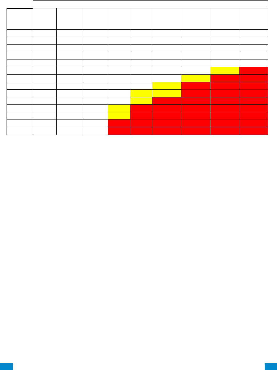
...C... 228 P/N 466-5261 • REV D ISS 17NOV17 UltraSync Modular Hub Reference Manual ©2016 United Technologies Corporation .... .I.....
Bus Voltage, 16 AWG Bus Wire
Bus Length in Feet
Bus
Current
mA
50
100
200
500
750
1000
1500
2000
2500
25
10.0
10.0
10.0
9.9
9.8
9.8
9.7
9.6
9.5
30
10.0
10.0
10.0
9.9
9.8
9.8
9.6
9.5
9.4
45
10.0
10.0
9.9
9.8
9.7
9.6
9.4
9.3
9.1
60
10.0
10.0
9.9
9.8
9.6
9.5
9.3
9.0
8.8
100
10.0
9.9
9.8
9.6
9.4
9.2
8.8
8.4
8.0
175
9.9
9.9
9.7
9.3
8.9
8.6
7.9
7.1
6.4
250
9.9
9.8
9.6
9.0
8.5
8.0
6.9
5.9
4.9
350
9.9
9.7
9.4
8.6
7.9
7.1
5.7
4.3
2.9
400
9.8
9.7
9.3
8.4
7.5
6.7
5.1
3.5
1.8
525
9.8
9.6
9.1
7.9
6.8
5.7
3.6
1.4
0.0
600
9.8
9.5
9.0
7.5
6.3
5.1
2.6
0.2
0.0
700
9.7
9.4
8.9
7.1
5.7
4.3
1.4
0.0
0.0
875
9.6
9.3
8.6
6.4
4.6
2.9
0.0
0.0
0.0
1000
9.6
9.2
8.4
5.9
3.9
1.8
0.0
0.0
0.0
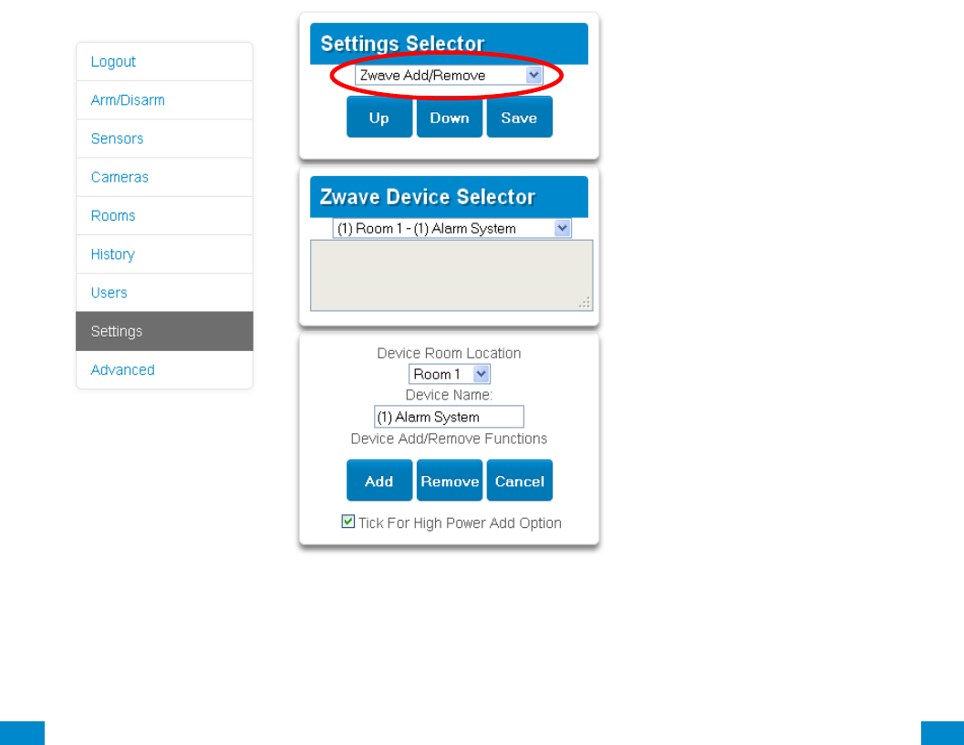
...C... 229 P/N 466-5261 • REV D ISS 17NOV17 UltraSync Modular Hub Reference Manual ©2016 United Technologies Corporation .... .I.....
A.15 Z-Wave Home Automation Hub
When the optional UM-ZW Z-Wave Module is added, this system is a Z-Wave security
enabled device allowing control of Z-Wave home automation devices. A secure Z-Wave
controller is required to fully utilize the product. The UltraSync Modular Hub can act as a
secure Z-Wave controller.
Z-Wave compliant devices regardless of manufacturer can be used in the same network and
always-on devices can function as repeaters to extend the range of Z-Wave devices.
Supported 3rd party Z-Wave devices include selected light switches, dimmers, thermostats,
and door locks. Door locks which support secure encryption can be used, unencrypted locks
cannot be added to this system.
This system may natively support setting and retrieving on/off states, setting and retrieving
dimming levels, and locking/unlocking.
Adding Z-Wave Devices
1. Log in to Web Server or UltraSync + app. Master access level is required for
programming the Z-Wave devices into UltraSync Modular Hub.
2. Click Settings, Rooms and edit Room Names.
3. Click Settings, Z-Wave Add/Remove.
4. If a Z-Wave device has been added previously to another system, the Z-Wave standard
requires it to be removed before adding it to a new system. To do this, click Remove,
then activate LINK or REMOVE mode on the device.
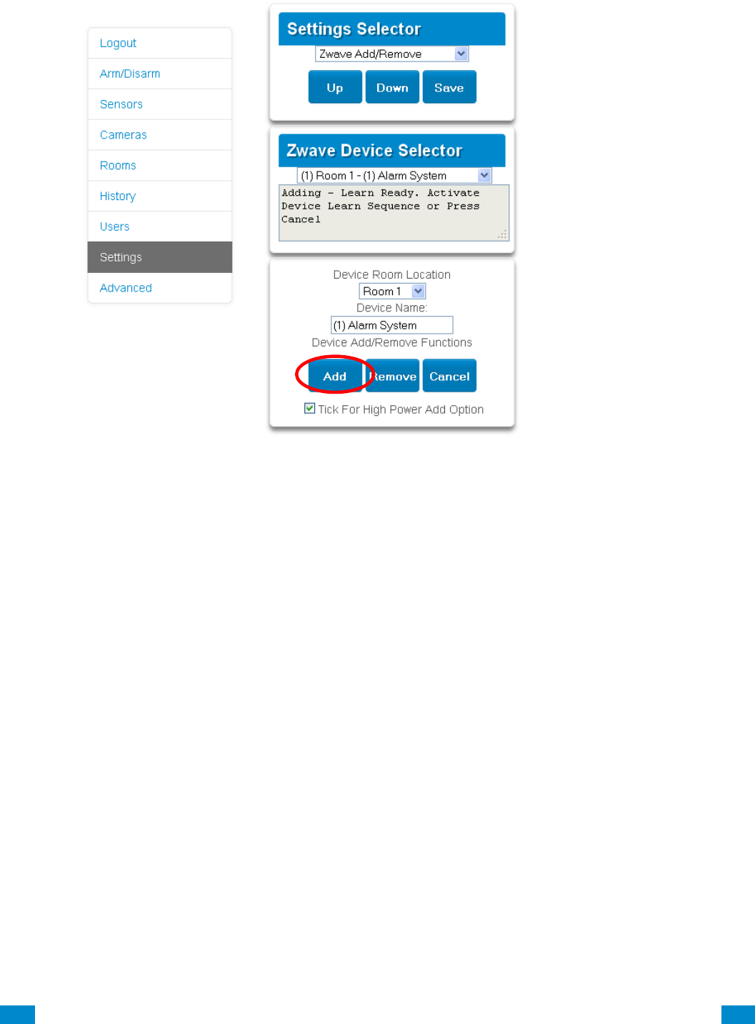
...C... 230 P/N 466-5261 • REV D ISS 17NOV17 UltraSync Modular Hub Reference Manual ©2016 United Technologies Corporation .... .I.....
5. Click Add.
6. Initiate LINK or ADD mode on Z-Wave device. See your Z-Wave device’s manual for
instructions.
7. Click Rooms.
8. The device will appear in the list. Click a button such as ON or OFF to verify you can
control the device.

...C... 231 P/N 466-5261 • REV D ISS 17NOV17 UltraSync Modular Hub Reference Manual ©2016 United Technologies Corporation .... .I.....
Programming a Z-Wave Siren
Some Z-Wave sirens identify themselves as a true siren, while others identify themselves
as binary on/off switches. There are different programming steps for each.
If you have added a Z-Wave siren that identifies as a binary on/off type, you can program it
to activate when the system siren activates:
1. Log in to Web Server or UltraSync + app.
2. Click Advanced\ Devices\ Zwave Devices\.
3. Select the Z-Wave siren in the drop down list.
4. Click Zwave Options.
5. Enable 'Siren Mode'.
6. Click Save.
7. Arm your system and trip a sensor to cause the system siren to activate. Verify your Z-
Wave siren also activates.
8. Disarm your system.
Some Z-wave sirens can follow each keypad beep during Exit Delay and Entry Delay. This
is enabled under:
1. Log in to UltraSync Modular Hub Web Server or UltraSync + app.
2. Click Advanced\ System\ Siren Options\.
3. Enable ' Z-Wave Siren Chirps Entry and Exit'.
4. Click Save.
When this option is off, only the system siren should sound during Entry and Exit Delay.
Note: Some Z-wave sirens have a built-in timer and ignore advanced features. They will
continue to sound for the duration of their internal timer.
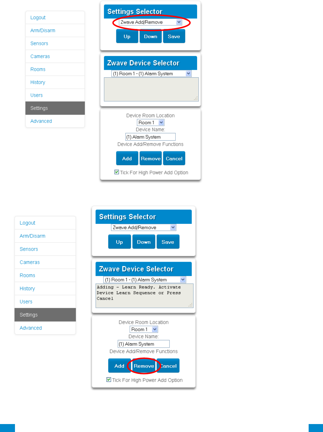
...C... 232 P/N 466-5261 • REV D ISS 17NOV17 UltraSync Modular Hub Reference Manual ©2016 United Technologies Corporation .... .I.....
Removing Z-Wave Devices
1. Log in to Web Server or UltraSync + app.
2. Click Settings, Z-Wave Add/Remove.
3. Click Remove.
4. Press the include button on the Z-Wave device you want to remove. See your Z-Wave
device’s manual for instructions.
5. Device will be removed.
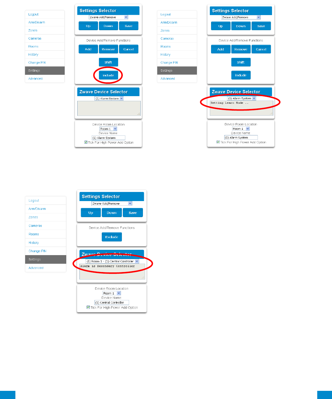
...C... 233 P/N 466-5261 • REV D ISS 17NOV17 UltraSync Modular Hub Reference Manual ©2016 United Technologies Corporation .... .I.....
Adding UltraSync Modular Hub to existing Z-Wave network as Secondary
Controller
1. Log in to Web Server or UltraSync + app.
2. Click Settings, Z-Wave Add/Remove.
3. Start the Add process on the primary controller of the existing network.
4. Press the Include button on the screen of the UltraSync Modular Hub (the secondary
device):
5. Primary Controller will add the UltraSync Modular Hub to it.
6. Status on screen will update to indicate it has been added as Secondary Controller.
7. Save settings on Primary Controller.
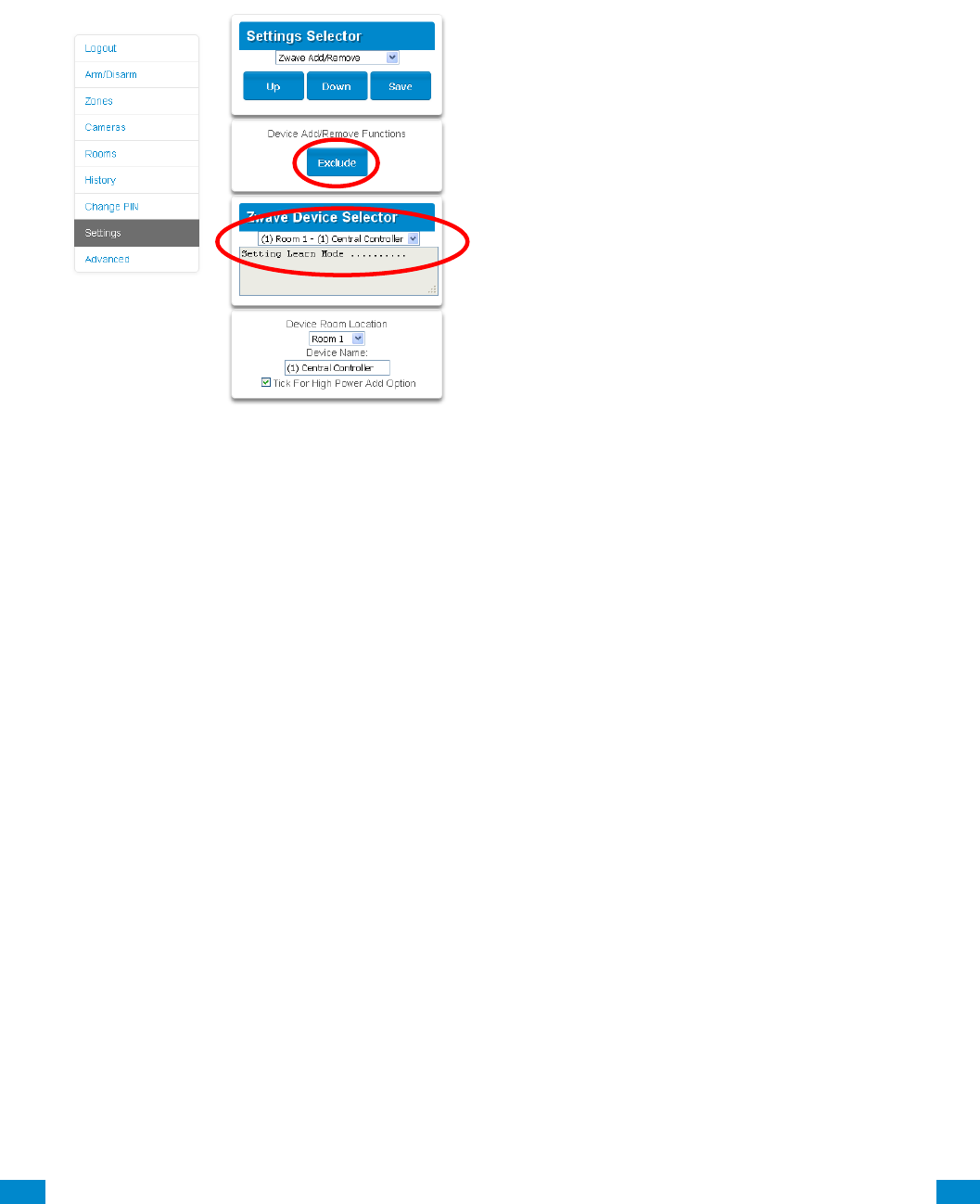
...C... 234 P/N 466-5261 • REV D ISS 17NOV17 UltraSync Modular Hub Reference Manual ©2016 United Technologies Corporation .... .I.....
Removing UltraSync Modular Hub from existing Z-Wave network as
Secondary Controller
1. Log in to Web Server or UltraSync + app.
2. Click Settings, Z-Wave Add/Remove.
3. Start the Remove process on the primary controller of the existing network.
4. Press the Exclude button on the UltraSync Modular Hub (the secondary device):
5. Primary Controller will remove UltraSync Modular Hub from it.
6. UltraSync Modular Hub status will update.
7. Save settings on Primary Controller.
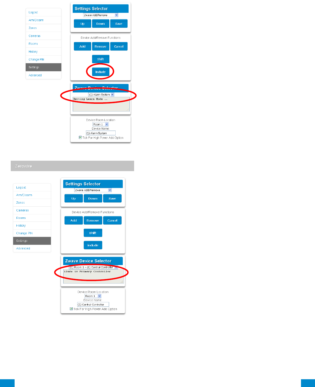
...C... 235 P/N 466-5261 • REV D ISS 17NOV17 UltraSync Modular Hub Reference Manual ©2016 United Technologies Corporation .... .I.....
Adding UltraSync Modular Hub to existing Z-Wave network as Primary
Controller
1. Log in to Web Server or UltraSync + app.
2. Click Settings, Z-Wave Add/Remove.
3. Start the Control Shift function on the primary controller of the existing network. This will
typically involve pressing a “Shift” button.
4. Press the Include button on the UltraSync Modular Hub (the secondary device):
5. UltraSync Modular Hub now displays “Alarm is Primary Controller” to indicate successful
shift:
6. UltraSync Modular Hub will now be the Primary Z-Wave Controller, and the other
network is the Secondary Z-Wave Controller.
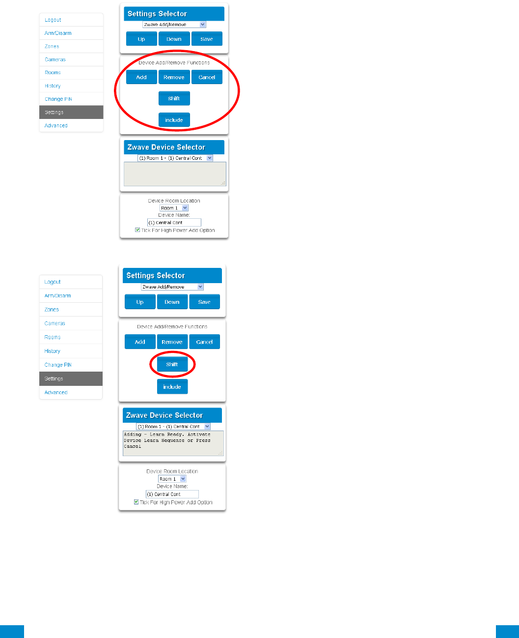
...C... 236 P/N 466-5261 • REV D ISS 17NOV17 UltraSync Modular Hub Reference Manual ©2016 United Technologies Corporation .... .I.....
Relinquish Primary Control of UltraSync Modular Hub to another
Controller
1. Log in to Web Server or UltraSync + app.
2. Click Settings, Z-Wave Add/Remove.
3. Check UltraSync Modular Hub is the primary controller and a secondary controller is
already learnt in to UltraSync Modular Hub. UltraSync Modular Hub in Primary Controller
mode will display Add Remove Cancel Shift and Include buttons:
4. Press the Shift button on UltraSync Modular Hub (the Primary Controller).
5. Press the Exclude button on the Secondary Controller.
6. UltraSync Modular Hub Primary Controller relinquishes control and becomes Secondary
Controller. Only the Exclude button is visible indicating the UltraSync Modular Hub is
Secondary Controller:

...C... 237 P/N 466-5261 • REV D ISS 17NOV17 UltraSync Modular Hub Reference Manual ©2016 United Technologies Corporation .... .I.....
7. Secondary Controller shifts into Primary Controller.
Replacing a Failed Node
1. Click Settings – Zwave Maintenance
2. On the Failed Device Selector, click the node to be replaced.
3. Click the Replace button.
4. Press the include button on the new node.
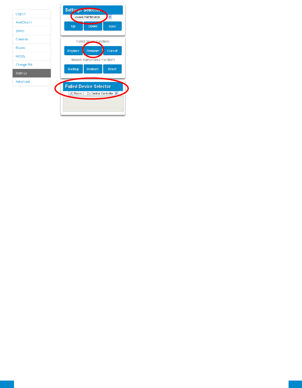
...C... 238 P/N 466-5261 • REV D ISS 17NOV17 UltraSync Modular Hub Reference Manual ©2016 United Technologies Corporation .... .I.....
Removing a Failed Node
1. Click Settings – Zwave Maintenance
2. On the Failed Device Selector, click the node to be removed.
3. Click the Remove button.
4. Status will show “Device Removed” when successful.
Send User PINs to Z-Wave Door Lock
UltraSync Modular Hub can send user PIN codes to an existing Z-Wave Door Lock so the
PIN codes on the alarm system can also be used to operate the door lock. This feature is
available to User Types – Engineer, Master, and Custom users with Z-Wave menu access.
Communication is one way from the UltraSync Modular Hub to the lock, instructing the lock
to add or remove PIN codes. Each lock is individually controlled.
When “Send PIN(s) to Lock” is selected, UltraSync Modular Hub queries the lock for the
number of standard users it supports. Some locks support up to 250 PINS, others are
limited to 40. Check your lock documentation.
Each UltraSync Modular Hub user number is sent to the same numbered slot in the lock, up
to the maximum slots available in the lock. For example, UltraSync Modular Hub user
number 1 will be sent to the Z-Wave Door Lock slot 1. Users exceeding the capacity of the
lock will not be sent.
Existing PIN codes in the door lock will be over-written. If the lock detects a duplicate PIN
then the send command will fail.
Selecting “Remove PIN(s) from Lock” will clear all PIN codes from the lock, whether or not
they were added by the UltraSync Modular Hub.
Some door locks have special master/installer PIN codes, these will not be changed.
However, if they are default standard user PIN codes then UltraSync Modular Hub will have
access to change or remove them. Each lock is different and you should test this feature on
your specific lock to ensure only the appropriate codes are present.
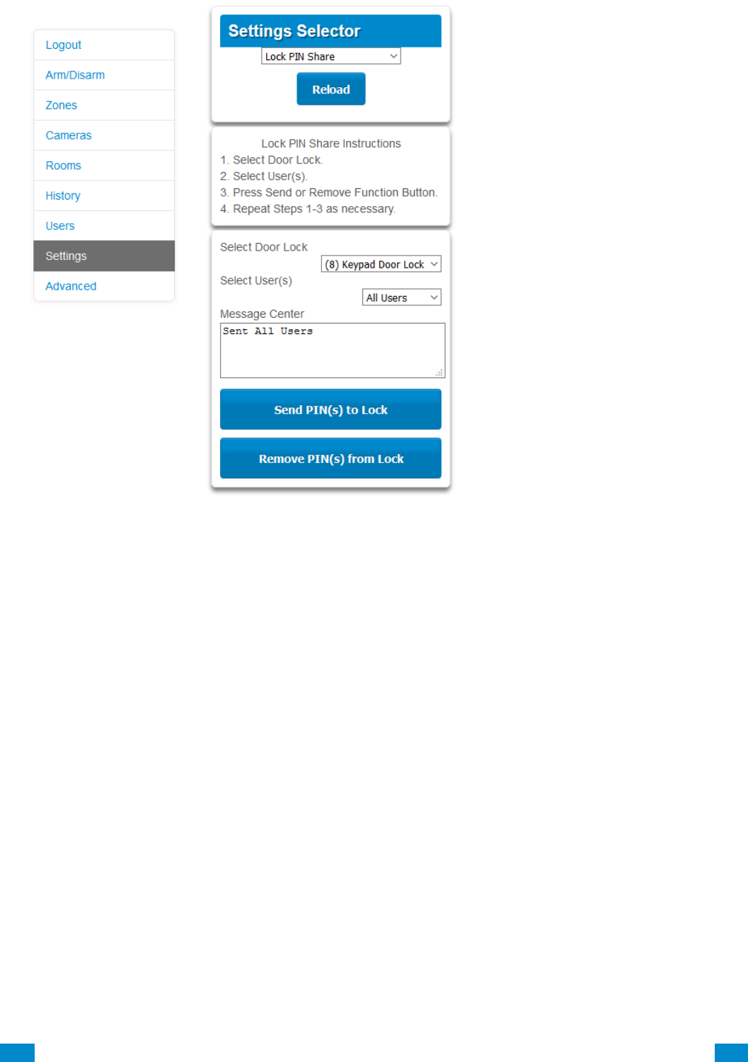
...C... 239 P/N 466-5261 • REV D ISS 17NOV17 UltraSync Modular Hub Reference Manual ©2016 United Technologies Corporation .... .I.....
1. Log in to UltraSync Modular Hub Web Server or UltraSync + app.
2. Click Settings – Lock PIN Share.
3. Select the Z-Wave Door Lock in the drop down list.
4. Wait for the “Building User List- Please Wait” message to be replaced with “Ready”.
5. The default will have “All Users” pre-selected. You may select an individual user instead.
6. Optional and recommended, click “Remove PIN(s) from Lock”. This ensures any extra
PIN codes are removed from the lock and only the PIN codes from UltraSync Modular
Hub can operate the lock. Once completed it will show “Removed All Users”.
7. Click “Send PIN(s) to Lock.
8. PIN codes will be sent to Z-Wave door lock one at a time. Once completed it will show
“Sent All Users”.
9. Test PIN codes on door lock and verify only the desired codes can operate the lock.
10. Refer to door lock manual to remove or change installer / master codes from door lock.
As PIN codes can also be changed on the door lock, over time there may be a mismatch in
PINs on the door lock compared to UltraSync Modular Hub. To avoid this confusion, only
make PIN code changes via UltraSync Modular Hub.

...C... 240 P/N 466-5261 • REV D ISS 17NOV17 UltraSync Modular Hub Reference Manual ©2016 United Technologies Corporation .... .I.....
UltraSync + app and Web Server Error Messages
Various error messages may appear on the UltraSync Modular Hub Web Server
and the UltraSync + application. These apply when the optional UM-ZW Z-wave
Module module is installed/
• "Unavailable - Failed Device Function in progress" - An attempt was made to
enter an add/ remove mode when the failed device mode is active.
• "Unavailable - Add mode active" - An attempt was made to enter an
add/remove mode when the add mode is active.
• "Unavailable - Remove mode active" - An attempt was made to enter an
add/remove mode when the remove mode is active.
• "Unavailable - Resetting Network" - An attempt was made to enter an
add/remove mode when the resetting mode is active.
• "Unavailable - Backing Up Network" - An attempt was made to enter an
add/remove mode when the backup mode is active.
• "Unavailable - Restoring Network" - An attempt was made to enter an
add/remove mode when the restore mode is active.
• "Busy, Try Again Momentarily" - This message is received when the Z-Wave
module is attempting to execute a command and a new command was
submitted.
• "Not primary controller" - An attempt was made to perform device functions
when not a primary controller.
• "Device Not found in failed list" - An attempt was made to remove a failed
device that is now responding.
• "Remove Device failed - already in process" - An attempt was made to enter a
remove mode when the remove mode is active.
• "Replace Device failed - already in process" - An attempt was made to enter a
replace mode when the replace mode is active.
• "Remove Failed" - An attempt to remove a device from the network has failed.
• "Replace Failed"- An attempt to replace a device from the network has failed.
• "Function timed out or cancelled" Add/Remove/Replace function timed out.
• "Unavailable, Try Again Later" - This message is received when the Z-Wave
module is still initializing.
• "Command Failed" - A Z-Wave command has failed.
• "You must press Select to choose a set point" - A set point change was
attempted without selecting a set point to change.
• "There are no Failed Devices" - Displayed in the failed device dialog when no
failed devices detected.

...C... 241 P/N 466-5261 • REV D ISS 17NOV17 UltraSync Modular Hub Reference Manual ©2016 United Technologies Corporation .... .I.....
Specifications
S.1 CPU Power Input Specifications
AC input: 16 - 18 VAC
DC input: 18 - 26 VDC
Auxiliary power output (POS/NEG) 13.8 VDC +/- 0.2 V, 1 A max.
Fused, self-resetting
Battery type Lead acid rechargeable
Maximum Battery Capacity 12 AH
Battery low condition From 10.0 VDC to 11.0 VDC
(If voltage falls below 11 VDC
a system event is generated)
Battery disconnect voltage 10.0 VDC (system shutdown)
S.2 System General Features
Code combinations From 10,000 (4 digits) to 100,000,000 (8 digits)
End-of-line resistor 820 Ω 2 wire smoke
3.3 kΩ (default)
3.74 kΩ and 6.98 kΩ zone double EOL
Onboard zones 8 (default); 16 if zone doubling enabled
Maximum sensor number:
UM-5000 500
Additional inputs 2 – box tamper
Onboard outputs 5
Maximum relays limited by bus capacity
Maximum actions 256, main panel supports 32 actions,
each relay expansion module adds 32 actions, 7
relay expansion modules will provide a maximum
of 256 actions
Areas 96
Keypads 64
Expansion Modules/Bus Devices 64 (including keypads)
Users 256
User Permissions 128
Non-volatile Memory
System event log capacity 1024
Video event log capacity 1024
Ethernet connection
Supported standard IEEE 802.3u
Speed 10BASE-T or 100BASE-TX
Duplex Half-duplex and full-duplex
Cabling FTP (foiled twisted pair) Cat 5e cable or better

...C... 242 P/N 466-5261 • REV D ISS 17NOV17 UltraSync Modular Hub Reference Manual ©2016 United Technologies Corporation .... .I.....
UltraSync Modular Hub bus
Type 4 wire RS485 Bus
High common mode tolerance (25V)
Range 2,600 ft. (800m)
Recommended Cable 2 pair twisted, 22 AWG data cable
Hardwired Zones
Wiring Resistance 200Ω maximum
S.3 Current Consumption*
Device
Voltage
Minimum
(device
shutdown)
Average*
Alarm**
(Maximum)
Comments
UM-5000-CPU
CPU output
10
100
100
Battery voltage level for
CPU shutdown.
UM-1820E
Keypad
7.75
90
175
UM-R4
4-Relay
Module***
6.55
25
125
25mA if no relays
are energized.
UM-R10
10-Relay
Module***
6.55
25
160
25 mA if no relays
are energized.
UM-Z8
8-Zone Module
6.55
35
35
Does not include
powered sensor current
UM-Z20
20-Zone Module
6.55
45
45
Does not include
powered sensor current
UM-W7
Wireless
Module***
7.75
40
65
40 mA relay off
65 mA relay energized
UM-C-H1
Cellular Module
NA
30
100
UM-ZW
Z-Wave Module
-
-
-
Output 1
NA
0
490 4 ohm
230 8 ohm
140 ma 16
ohm
Typical values for
speaker operation.
Consult DC Siren
specifications for value
Output 2
NA
0
0
Connection dependent
Output 3
NA
0
0
Connection dependent
Output 4
NA
0
0
Connection dependent
Output 5
NA
0
0
Connection dependent
* Use for battery backup calculation
** Use for power supply calculation and 5 minute battery backup calculation
*** Max current value is assuming all relays on the module are energized.
If relays are inactive, calculation can be de-rated 25 mA per inactive relay.
If positive switching is utilized, additional current draw of connected load must be included
in power budget calculations.
Consult current product documentation for the most up-to-date consumption rates

...C... 243 P/N 466-5261 • REV D ISS 17NOV17 UltraSync Modular Hub Reference Manual ©2016 United Technologies Corporation .... .I.....
S.4 Battery Capacity Calculations
When performing battery backup calculations, determine the entire system average and
maximum current draw per the table above. . If you are powering hardwired zones from the
CPU or zone expansion modules, remember to include the current draw from the sensors in
your current calculation.
Sample Current Budget
Average
Current (mA)
Alarm/Maximum
Current (mA)
550
950
With these system current values calculated, determine the required battery capacity, in Amp
Hours (AH), to provide the required backup time. Below are sample battery backup
calculations.
24 hr. Battery Backup Calculation
Formula
Amp
Hours
24 hour non-Alarm Amp Hour Calculation
550*24/1000
13.20
5 minute Alarm Amp Hour Calculation
950*5/60/1000
0.08
Total Battery Requirements in Amp Hours
13.28
4 hr. Battery Backup Calculation
Formula
Amp
Hours
4 hour non-Alarm Amp Hour Calculation
550*4/1000
2.20
5 minute Alarm Amp Hour Calculation
950*5/60/1000
0.08
Total Battery Requirements in Amp Hours
2.28
Battery Options
Part Number
Capacity
60-681
4 Amp Hours
60-680
7 Amp Hours
60-781
17.2 Amp Hours
In this example, a 17 Amp Hour battery would be required for 24 hour backup and a 4 Amp
Hour battery would be required for 4 hour backup.

...C... 244 P/N 466-5261 • REV D ISS 17NOV17 UltraSync Modular Hub Reference Manual ©2016 United Technologies Corporation .... .I.....
S.5 Environmental
Operating temperature +14°F to +131°F (-10 to +55°C)
Humidity 95% non-condensing
S.6 Physical Dimensions
Product
Main description
Dimensions (LxWxH)
UM-5000
500 Zone CPU w/ IP & PSTN
4.64” x 5.55” x 2.0”
(118 x 141 x 51mm)
UM-PE
Plastic Enclosure
13.3” x 13.3” x 3.7”
(338 x 338 x 94mm)
UM-CME
Metal Enclosure
18.58” x 15.55” x 4.33”
(472 x 395 x 110mm)
UM-1820E
Touchscreen keypad
.70” x 3.27” x 4.92”
(18 x 82 x 125mm)
UM-Z8
8 zone expansion module
4.64” x 2.79” x 2.0”
(118 x 71 x 51mm)
UM-Z20
20 zone expansion module
4.64” x 2.79” x 2.52”
(118 x 71 x 64mm)
UM-R4
4 relay expansion module
4.64” x2.79” x 2.0”
(118 x 71 x 51mm)
UM-R10
10 relay expansion module
4.64” x 2.79” x 2.52”
(118 x 71 x 64mm)
S.7 Fuses
Battery 4 A, self-resetting
12 V aux 2 A, self-resetting
System LAN 2 A, self-resetting
Output, high current output J10 POS |
Siren, high current output J7 OP1+ | 2A combined
Strobe, high current output J7 OP2+ |
S.8 Maintenance
No regular maintenance needed. System will report servicing when necessary.
S.9 System Monitoring
The system provides monitoring for the following items.
Monitoring function
Message
Cause
AC Mains
Mains fail
Loss of external power supply [1]
Battery
Battery low
Battery low voltage [1]
Battery test fail
Exhausted battery
Battery charger fail
Fuse/power output fail
Output overload

...C... 245 P/N 466-5261 • REV D ISS 17NOV17 UltraSync Modular Hub Reference Manual ©2016 United Technologies Corporation .... .I.....
Monitoring function
Message
Cause
Power outputs
Fuse/power output fail
Exhausted fuse
Fuse loss
Short circuit
Overload
Power supply
Power unit/power output fail
Power unit failure
Overvoltage
Tampers
Device tamper
Device sabotage
S.10 SIA and CID Reporting Code Descriptions
#
SIA
code
CID
code
Function
Note
Reporting
priority
1.
AN
R393
Detector dirty restore
Low
2.
AR
R301
AC restore
Low
3.
AS
E393
Detector dirty
Low
4.
AT
E301
AC trouble
Medium
5.
BA
E130
Burglary alarm
Alarm / input in mask / trouble when set
Medium
6.
BB
E570
Burglary bypass
Alarm inhibit
Low
7.
BC
E406
Burglary cancel
Cancel alarm by user / key / remotely
Low
8.
BJ
R381
Detector supervision restore
Low
9.
BR
R130
Burglary restore
Low
10.
BT
E380
Burglary trouble
Input in mask / trouble when unset
Low
11.
BU
R570
Burglary unbypass
Alarm uninhibit
Low
12.
BV
E139
Alarm confirm
ACPO
Medium
13.
BW
R139
Restore confirmed alarm
ACPO
Low
14.
BZ
E381
Detector supervision
Low
15.
CF
E408
Forced closing
Set by user / by key
Low
16.
CG
E456
Part set
Part set by user / by key / remotely
Low
17.
CL
R401
Closing normal
Set by user
Low
R407
Closing normal
Set remotely
Low
R409
Closing normal
Set by key
Low
18.
EE
E374
Exit error
Exit fault
Medium
19.
ER
R143
Expansion restore
Expander / keypad trouble restore
Low
R300
Expansion restore
Expander fuse restore
Low
R330
Expansion restore
Expander / keypad communication restore
Low
20.
ET
E143
Expansion trouble
Expander / keypad trouble
Low
E300
Expansion trouble
Expander fuse failure
Low
E330
Expansion trouble
Expander / keypad communication fault
Low
21.
FA
E110
Fire alarm
High

...C... 246 P/N 466-5261 • REV D ISS 17NOV17 UltraSync Modular Hub Reference Manual ©2016 United Technologies Corporation .... .I.....
#
SIA
code
CID
code
Function
Note
Reporting
priority
22.
FB
E570
Fire bypass
Fire inhibit
Low
23.
FJ
R373
Fire trouble restore
Low
24.
FR
R110
Fire restore
Low
25.
FT
E373
Fire trouble
Low
26.
FU
R570
Fire unbypass
Fire uninhibit
Low
27.
FW
–
Fire long supervision
Low
28.
HA
E121
Holdup alarm
Duress
High
29.
HR
R121
Holdup restore
Duress restore
Low
30.
JP
E466
Service in
Low
31.
JR
R466
Service out
Low
32.
JT
E625
Time changed
Low
33.
LB
E627
Local programming begin
Low
34.
LR
R351
Line restore
Low
35.
LS
R628
Local programming stop
Low
36.
LT
E351
Line fault
Low
37.
MA
E100
Medical alarm
High
38.
MB
E570
Medical bypass
Low
39.
MJ
–
Medical long supervision
restore
Low
40.
MR
R100
Medical restore
Low
41.
MS
–
Medical long supervision
Low
42.
MU
R570
Medical unbypass
Low
43.
OP
E401
Unset normal
Unset by user
Low
E407
Unset normal
Unset remotely
Low
E409
Unset normal
Unset by key
Low
44.
OR
E406
Unset from alarm
Unset by user / key / remotely
Low
45.
PA
E120
Panic alarm
High
46.
PB
E570
Panic bypass
Low
47.
PJ
R375
Panic trouble restore
Low
48.
PR
R120
Panic restore
Low
49.
PT
E375
Panic trouble
Low
50.
PU
R570
Panic unbypass
Low
51.
RB
E416
Remote programming begin
Low
52.
RP
E602
Automatic test / ring-in test
Low
53.
RR
E305
Power up
System power-up
Low
54.
RS
R416
Remote programming success
Low
55.
RU
R416
Remote programming fail
Low
56.
RX
E601
Manual CS test
Low

...C... 247 P/N 466-5261 • REV D ISS 17NOV17 UltraSync Modular Hub Reference Manual ©2016 United Technologies Corporation .... .I.....
#
SIA
code
CID
code
Function
Note
Reporting
priority
57.
TA
E144
Tamper alarm
Zone tamper
Medium
E145
Tamper alarm
Medium
E320
Tamper alarm
Expander siren tamper
Medium
58.
TB
E570
Tamper bypass
Low
59.
TR
R144
Tamper restore
Zone tamper restore
Low
R145
Tamper restore
Low
R320
Tamper restore
Expander siren restore
Low
R370
Tamper restore
KeyBox tamper restore
Low
60.
TT
E370
KeyBox zone active
High
61.
TU
R570
Tamper unbypass
Low
62.
UB
E570
Expander / keypad /
sensorbypassed
Expander / keypad / zone isolated
Low
63.
UU
R570
Expander / keypad / zone
unbypassed
Expander / keypad / zone de-isolated
Low
64.
WF
E612
Walk test fail
Low
65.
WP
E611
Walk test pass
Low
66.
XH
R344
RF jamming restore
Low
67.
XQ
E344
RF jamming
Low
68.
XR
R384
Detector or fob low battery
restore
Low
69.
XT
E384
Detector or fob low battery
Low
70.
YC
E350
Communications fail
ISDN / GSM / voice / audio device fail
Low
71.
YK
R354
Communications restore
ISDN / GSM / voice / audio device restore
Low
72.
YR
R302
System battery / fuse restore
Expander / dialler battery / fuse restore
Low
73.
YS
E354
Communication trouble
Fail To Communicate (FTC)
Low
74.
YT
E302
System battery / fuse trouble
Expander / dialler battery low / fuse fault
Low
75.
ZA
E152
Technical alarm — low
temperature
Low temperature detector alarm
Medium
76.
ZB
E570
Technical bypass — low
temperature
Low temperature detector inhibit
Low
77.
ZJ
R381
Technical long supervision
restore — low temperature
Low temperature detector long supervision
restore
Low
78.
ZR
R152
Technical restore — low
temperature
Low temperature detector restore
Low
79.
ZS
E381
Technical long supervision —
low temperature
Low temperature detector long supervision
alarm
Low
80.
ZU
R570
Technical unbypass — low
temperature
Low temperature detector uninhibited
Low
81.
YA
E321
Siren fault
Low
82.
YH
R321
Siren restore
Low

...C... 248 P/N 466-5261 • REV D ISS 17NOV17 UltraSync Modular Hub Reference Manual ©2016 United Technologies Corporation .... .I.....
#
SIA
code
CID
code
Function
Note
Reporting
priority
83.
NC
E356
CS polling fail
Heartbeat inactive
Low
84.
NR
R356
CS polling restore
Heartbeat active
Low
85.
CP
R403
Auto set
Set by schedule
Low
86.
OA
E403
Auto unset
Unset by schedule
Low
87.
OT
E608
Late close
Postponed auto set
Low
88.
OK
R608
Early open
Manually unset before auto unset
Low
89.
IA
E313
Engineer reset request
Low
90.
IR
R313
Engineer reset restore
Low
91.
GA
E151
Technical alarm — gas
Gas detector alarm
High
92.
GR
R151
Technical restore — gas
Gas detector restore
High
93.
GB
E570
Technical bypass — gas
Gas detector inhibit
Low
94.
GU
R570
Technical unbypass — gas
Gas detector uninhibit
Low
95.
GS
E381
Technical long supervision —
gas
Gas detector long supervision alarm
Low
96.
GJ
R381
Technical long supervision
restore — gas
Gas detector long supervision restore
Low
97.
KA
E158
Technical alarm — high
temperature
High temperature detector alarm
Medium
98.
KR
R158
Technical restore — high
temperature
High temperature detector restore
Medium
99.
KB
E570
Technical bypass — high
temperature
High temperature detector inhibit
Low
100.
KU
R570
Technical unbypass — high
temperature
High temperature detector uninhibit
Low
101.
KS
E381
Technical long supervision —
high temperature
High temperature detector long supervision
alarm
Low
102.
KJ
R381
Technical long supervision
restore — high temperature
High temperature detector long supervision
restore
Low
103.
WA
E154
Technical alarm — water
Water detector alarm
Medium
104.
WR
R154
Technical restore — water
Water detector restore
Medium
105.
WB
E570
Technical bypass — water
Water detector inhibit
Low
106.
WU
R570
Technical unbypass — water
Water detector uninhibit
Low
107.
WS
E381
Technical long supervision —
water
Water detector long supervision alarm
Low
108.
WJ
R381
Technical long supervision
restore — water
Water detector long supervision restore
Low
109.
ES
E145
Tamper alarm
Expander / keypad tamper alarm
Medium
110.
EJ
R145
Tamper restore
Expander / keypad tamper restore
Medium
111.
HV
E129
Hold-up alarm confirm
Medium
112.
HW
R129
Confirmed hold-up alarm
restore
Low

...C... 249 P/N 466-5261 • REV D ISS 17NOV17 UltraSync Modular Hub Reference Manual ©2016 United Technologies Corporation .... .I.....
#
SIA
code
CID
code
Function
Note
Reporting
priority
113.
UA
E150
Technical zone — general
alarm
Medium
114.
UR
R150
Technical zone — general
alarm restore
Medium
115.
TS
E607
Single zone walk test start
Start of single zone test, also for multiple
zones selected
High
116.
TE
R607
Single zone walk test end
End of single zone test, also for multiple
zones selected
Low
117.
LU
R628
Local programming fail
Low
118.
YP
E301
Power Supply Trouble
Low
119.
YQ
R301
Power Supply Restored
Low

...C... 250 P/N 466-5261 • REV D ISS 17NOV17 UltraSync Modular Hub Reference Manual ©2016 United Technologies Corporation .... .I.....
UL Specification
General: The UL Listed system consists of the following features and compatible devices:
Electrical:
Software Version:
1.x
Installation Notes:
The system shall not be programmed to add input from the Web Server, UltraSync App, and
Wi Fi to smartphone.
The chime feature is only to be used in the disarm stage. It is not to be used as the main
audible alarm.
During the test mode, test AC and Battery every week by disconnecting AC power and
verifying 5 minutes of emergency signaling. Reinstall restraining means of power plug.
Replace the battery every xx years.
The RF jamming signal is displayed on the keypad and repeats until code is entered.
Compatible Receivers:
Operation has been verified with industry standard SIA Contact ID format. It is the Installer’s
responsibility to verify compatibility between the panel and the receiver used during
installation. The Installer shall verify the compatibility of the receiver and the system on a
yearly basis.
Listings and Approvals:
UL:
ANSI/UL 985 Household Fire Warning
ANSI/UL 1023 Household Burglar
ANSI/UL 1637 Home Health Care Signaling
cUL:
ULC S545 – Residential Fire Warning System Control Units
ULC/ORD-C1023 – Preliminary Standard for Household Burglar Alarm System Units
SIA:
ANSI/SIA CP-01-2010 False Alarm Reduction
Minimum System Configuration:
Control Panel UM-5000 for use with the following UL Listed accessories manufactured by
UTC:
TX-1012-01-1, TX-1012-01-3 DOOR CONTACT
60-362N-10-319.5 DOOR CONTACT
TX-6010-01-1 SMOKE DETECTOR
60-848-02-95 SMOKE DETECTOR
60-703-95 PIR
60-639-95R PIR
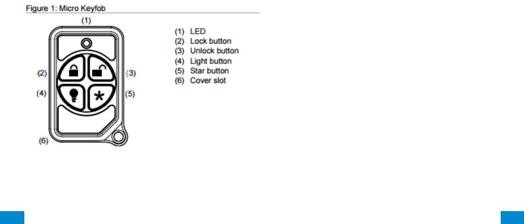
...C... 251 P/N 466-5261 • REV D ISS 17NOV17 UltraSync Modular Hub Reference Manual ©2016 United Technologies Corporation .... .I.....
Abort:
Consult with your Installer to determine if your system is configured with a communicator
delay. A communicator delay will prevent a report to the central station if the control panel is
disarmed within 30-45 seconds after an intrusion alarm is triggered. Note: Fire-type alarms
are normally reported without a delay.
Quick exit:
Use the quick exit feature when someone wants to briefly leave while the home is still armed
(for instance to get the newspaper). This feature needs to be enabled by your Installer. When
you press the DISARM button, the display shows Exit Time is On. This allows a designated
exit door to be open for up to two minutes without triggering an alarm.
Note: The designated door may be opened and closed only once. If you close the designated
door behind you when you exit, you will have to disarm the system upon reentering. Leave
the designated door open while using the quick exit feature.
Note: The designated door may be opened and closed only once. If you close the designated
door behind you when you exit you will have to disarm the system upon reentering. Leave the
designated door open while using the quick exit feature.
Exit delay extension:
If enabled by your Installer, the Exit Delay extension feature will recognize when you arm the
system, leave your house and then quickly re-enter your house (such as you would if you
forgot your car keys.) In such a case ZX-6400 will restart your exit delay to give you the full
exit delay again.
Exit Progress Annunciation:
A pulsating audible sounds throughout the duration of the Exit Time to indicate that the exit
period is in process. A rapid pulsating audible sounds during the last ten (10) seconds of the
Exit Time to indicate that the Exit Time is running out.
Entry Progress Annunciation:
A pulsating audible sounds upon entry to indicate that the Entry Delay has begun.
Remote Control Devices: UTC model 6001064-95R

...C... 252 P/N 466-5261 • REV D ISS 17NOV17 UltraSync Modular Hub Reference Manual ©2016 United Technologies Corporation .... .I.....
Keyfob operation / System Acknowledgement:
Unlock button. Disarm the system. LED light momentary on and two squawks from the
control panel
Lock button. Arm the system. LED light momentary on and two squawks from the control
panel
Light button. Toggle system-controlled lights on/off (if programmed).
Star button. As programmed in the system.
When the battery is low, the LED light will not turn on when buttons are pressed, and the
keyfob will not operate.
Canceling and preventing accidental alarms:
One of the biggest concerns you might have regarding your security system is causing an
accidental alarm. Most accidental alarms occur when leaving the residence after arming the
system or before disarming the system upon your return.
Alarms are canceled by entering a valid master or user code within the minimum cancel
window of five (5) minutes. After alarms are canceled, the system will be disarmed.

...C... 253 P/N 466-5261 • REV D ISS 17NOV17 UltraSync Modular Hub Reference Manual ©2016 United Technologies Corporation .... .I.....
Recent Closing:
Enabled (2-minute window)
Sensor Tripping Instructions:
Sensor
Action
Door/window
Open the secured door or window.
Carbon monoxide alarm
Press and hold the Test/Hush button (approximately 5
seconds) until the unit beeps two times, and then release the
button.
Glass break
Test with an appropriate glass break sensor tester.
Motion sensor
Avoid the motion sensor field of view for 5 minutes, and then
enter its view.
Smoke
Press and hold the test button until the system sounds
transmission beeps.
Keyfob
Press and hold the Lock and Unlock buttons simultaneously
for 3 seconds.
Remote touchpad
Press and hold the two Emergency buttons simultaneously for
3 seconds.

...C... 254 P/N 466-5261 • REV D ISS 17NOV17 UltraSync Modular Hub Reference Manual ©2016 United Technologies Corporation .... .I.....
SIA CP-01-2010 Programmable Features
This system is shipped with preset defaults to comply with the Security Industry Association
CP-01 Standard. The relevant settings are listed below and should not be changed to
maintain CP-01 compliance.
FEATURE
REQUIREMENT
RANGE
SHIPPING
DEFAULT
Exit Time
Required
(programmable)
For full or auto arming:
45 sec. - 2 min.
(255 sec. max.)
60 Seconds
Progress
Annunciation /
Disable - for Silent
Exit
Allowed
Individual keypads may be disabled
All annunciators enabled
Exit Time Restart
Required Option
For re-entry during exit time
Enabled
Auto Stay Arm on
Unvacated Premises
Required Option
(except for remote arm)
If no exit after full arm
Enabled
Exit Time and
Progress
Annunciation /
Disable - for Remote
Arm
Allowed Option
(for remote arm)
May be disabled - for remote arming
Enabled
Entry Delay(s)
Required
(programmable)
30 sec. - 4 min. **
30 Seconds
Abort Window – for
Non-Fire Sensors
Required Option
May be disabled - by sensor or
sensor type
Enabled
Abort Window Time
– for Non-Fire
Sensors
Required
(programmable)
0 sec. - 45 sec. **
30 Seconds
Abort annunciation
Required Option
Annunciate that no alarm was
transmitted
Enabled
Cancel Window
Required
Minimum duration of the window
shall be five (5) minutes.
Cancel Annunciation
Required Option
Annunciate that a Cancel was
transmitted
Enabled
Duress Feature
Allowed Option
No automatic derivative of another
user code
No duplicates with other user codes
Disabled
Cross Zoning
Required Option
Programming needed
Disabled
Programmable
Cross Zoning Time
Allowed
May Program
Per manufacturer
Swinger Shutdown
Required
(programmable)
For all non-fire sensors, shut down
at 1 to 6 trips
Two trips
Swinger Shutdown
Disable
Allowed
For non- police response sensors
Enabled
Fire Alarm
Verification
Required Option
Depends on panel and sensors
Disabled
Call Waiting Cancel
Required Option
Depends on user phone line
Disabled
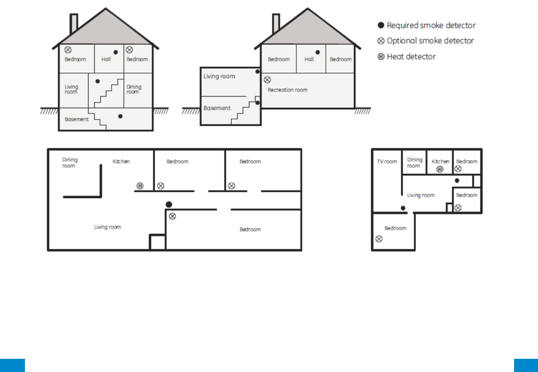
...C... 255 P/N 466-5261 • REV D ISS 17NOV17 UltraSync Modular Hub Reference Manual ©2016 United Technologies Corporation .... .I.....
Smoke and heat detector locations:
Selecting a suitable location is critical to the operation of smoke alarms. Figure 2 shows
some typical floorplans with recommended smoke and heat detector locations. Use these
location guidelines to optimize performance and reduce the chance of false alarms:
Before mounting alarms, program (learn) them into memory and do a sensor test from the
alarm’s intended location to ensure good RF communication to the panel.
Locate the alarm in environmentally controlled areas where the temperature range is
between 40 and 100°F (5 and 38°C) and the humidity is between 0 and 90%
noncondensing.
Locate alarms away from ventilation sources that can prevent smoke from reaching the
alarm.
Locate ceiling mounted alarms in the center of the room or hallway, at least 4 in. (10 cm)
away from any walls or areas.
Locate wall mounted alarms so the top of the alarm is 4 to 12 in. (10 to 31 cm) below the
ceiling.
In rooms with sloped, peaked, or gabled ceilings, locate alarms 3 ft. (0.9 m) down or away
from the highest point of the ceiling.
When mounting to suspended ceiling tile, the tile must be secured with the appropriate
fasteners to prevent tile removal.
Note: Do not mount the alarm to the metal runners of suspended ceiling grids. The metal
runners can draw the magnet’s field away from the alarm’s reed switch and cause a false
tamper alarm.
Figure 2. Smoke and Heat Detector Locations:

...C... 256 P/N 466-5261 • REV D ISS 17NOV17 UltraSync Modular Hub Reference Manual ©2016 United Technologies Corporation .... .I.....
Product Warnings
THESE PRODUCTS ARE INTENDED FOR SALE TO, AND INSTALLATION BY, AN EXPERIENCED
SECURITY PROFESSIONAL. INTERLOGIX CANNOT PROVIDE ANY ASSURANCE THAT ANY
PERSON OR ENTITY BUYING ITS PRODUCTS, INCLUDING ANY “AUTHORIZED DEALER”, IS
PROPERLY TRAINED OR EXPERIENCED TO CORRECTLY INSTALL SECURITY RELATED
PRODUCTS.
A PROPERLY INSTALLED AND MAINTAINED ALARM/SECURITY SYSTEM MAY ONLY REDUCE
THE RISK OF EVENTS SUCH AS BREAK-INS, BURGLARY, ROBBERY OR FIRE; IT IS NOT
INSURANCE OR A GUARANTEE THAT SUCH EVENTS WILL NOT OCCUR, THAT ADEQUATE
WARNING OR PROTECTION WILL BE PROVIDED, OR THAT THERE WILL BE NO DEATH,
PERSONAL INJURY, AND/OR PROPERTY DAMAGE AS A RESULT.
WHILE INTERLOGIX MAKES REASONABLE EFFORTS TO REDUCE THE PROBABILITY THAT A
THIRD PARTY MAY HACK, COMPROMISE OR CIRCUMVENT ITS SECURITY PRODUCTS OR
RELATED SOFTWARE, ANY SECURITY PRODUCT OR SOFTWARE MANUFACTURED, SOLD
OR LICENSED BY INTERLOGIX, MAY STILL BE HACKED, COMPROMISED AND/OR
CIRCUMVENTED.
INTERLOGIX DOES NOT ENCRYPT COMMUNICATIONS BETWEEN ITS ALARM OR SECURITY
PANELS AND THEIR OUTPUTS/INPUTS INCLUDING, BUT NOT LIMITED TO, SENSORS OR
DETECTORS UNLESS REQUIRED BY APPLICABLE LAW. AS A RESULT THESE
COMMUNICATIONS MAY BE INTERCEPTED AND COULD BE USED TO CIRCUMVENT YOUR
ALARM/SECURITY SYSTEM.
BATTERY OPERATED SENSORS, DETECTORS, KEYFOBS, PANIC DEVICES AND OTHER
PANEL ACCESSORIES HAVE A LIMITED BATTERY LIFE. WHILE THESE PRODUCTS ARE
DESIGNED TO PROVIDE SOME WARNING OF IMMINENT BATTERY DEPLETION THE ABILITY
TO DELIVER SUCH WARNINGS IS LIMITED AND SUCH WARNINGS MAY NOT BE PROVIDED IN
ALL CIRCUMSTANCES. PERIODIC TESTING OF THE SYSTEM IN ACCORANCE WITH THE
INSTRUCTIONS PROVIDED IN THE USER MANUAL IS THE ONLY WAY TO ENSURE ALL
SENSORS, DETECTORS, KEYFOBS, PANIC DEVICES AND OTHER PANEL ACCESSORIES ARE
FUNCTIONING PROPERLY.
CERTAIN SENSORS, PANIC DEVICES AND OTHER PANEL ACCESSORIES MAY BE
PROGRAMMED AS “SUPERVISORY” INTO THE ALARM PANEL MEANING THAT THE ALARM
PANEL WILL INDICATE A TROUBLE IN THE EVENT IT DOES NOT RECEIVE A REGULAR
SIGNAL FROM THE DEVICE WITHIN A CERTAIN PERIOD OF TIME (E.G. 12 HOURS). CERTAIN
DEVICES CANNOT BE PROGRAMMED AS SUPERVISORY. DEVICES CAPABLE OF BEING
PROGRAMMED INTO AN ALARM PANEL AS SUPERVISORY MAY NOT BE PROPERLY
PROGRAMMED RESULTING IN A FAILURE TO REPORT TROUBLE WHICH COULD RESULT IN
DEATH, SERIOUS INJURY OR PROPERTY DAMAGE.
WARNING: DO NOT CONNECT MAINS VOLTAGE DIRECTLY TO ANY COMPONENT OF THE
ULTRASYNC MODULAR HUB OTHER THAN AN APPROVED TRANSFORMER. DOING SO
COULD DAMAGE THE COMPONENTS AND POSE AN ELECTRICAL HAZARD THAT COULD
RESULT IN A FIRE OR CAUSE SERIOUS ELECTRICAL SHOCK OR LOSS OF LIFE.

...C... 257 P/N 466-5261 • REV D ISS 17NOV17 UltraSync Modular Hub Reference Manual ©2016 United Technologies Corporation .... .I.....
Warranty Disclaimers
INTERLOGIX HEREBY DISCLAIMS ALL WARRANTIES AND REPRESENTATIONS, WHETHER
EXPRESS, IMPLIED, STATUTORY OR OTHERWISE INCLUDING (BUT NOT LIMITED TO) ANY
WARRANTIES OF MERCHANTABILITY OR FITNESS FOR A PARTICULAR PURPOSE WITH
RESPECT TO ITS SECURITY PRODUCTS AND RELATED SOFTWARE. INTERLOGIX FURTHER
DISCLAIMS ANY OTHER IMPLIED WARRANTY UNDER THE UNIFORM COMPUTER
INFORMATION TRANSACTIONS ACT OR SIMILAR LAW AS ENACTED BY ANY STATE.
(USA only) SOME STATES DO NOT ALLOW THE EXCLUSION OF IMPLIED
WARRANTIES, SO THE ABOVE EXCLUSION MAY NOT APPLY TO YOU. THIS
WARRANTY GIVES YOU SPECIFIC LEGAL RIGHTS AND YOU MAY ALSO HAVE OTHER
LEGAL RIGHTS THAT VARY FROM STATE TO STATE.
INTERLOGIX MAKES NO REPRESENTATION, WARRANTY, COVENANT OR PROMISE THAT ITS
SECURITY PRODUCTS AND/OR RELATED SOFTWARE (I) WILL NOT BE HACKED,
COMPROMISED AND/OR CIRCUMVENTED; (II) WILL PREVENT, OR PROVIDE ADEQUATE
WARNING OR PROTECTION FROM, BREAK-INS, BURGLARY, ROBBERY, FIRE; OR (III) WILL
WORK PROPERLY IN ALL ENVIRONMENTS AND APPLICATIONS.
Disclaimer
THE INFORMATION IN THIS DOCUMENT IS SUBJECT TO CHANGE WITHOUT NOTICE. UTC
ASSUMES NO RESPONSIBILITY FOR INACCURACIES OR OMISSIONS AND SPECIFICALLY
DISCLAIMS ANY LIABILITIES, LOSSES, OR RISKS, PERSONAL OR OTHERWISE, INCURRED AS
A CONSEQUENCE, DIRECTLY OR INDIRECTLY, OF THE USE OR APPLICATION OF ANY OF
THE CONTENTS OF THIS DOCUMENT. FOR THE LATEST DOCUMENTATION, CONTACT YOUR
LOCAL SUPPLIER OR VISIT US ONLINE AT WWW.INTERLOGIX.COM
This publication may contain examples of screen captures and reports used in daily
operations. Examples may include fictitious names of individuals and companies. Any
similarity to names and addresses of actual businesses or persons is entirely coincidental.
The illustrations in this manual are intended as a guide and may differ from your actual unit
as UltraSync is continually being improved.
Intended Use
Use this product only for the purpose it was designed for; refer to the data sheet and user
documentation. For the latest product information, contact your local supplier or visit us online
at www.interlogix.com
The system should be checked by a qualified technician at least every 3 years and the
backup battery replaced as required.
Copyright
© 2016 United Technologies Corporation. All rights reserved.
Trademarks and Patents
All trademarks are the property of their respective owners. Interlogix, UltraSync name and
logo are trademarks of United Technologies Corporation. Interlogix is part of UTC Climate,
Controls & Security, a unit of United Technologies Corporation. IOS is the registered
trademark of Cisco Technology, Inc. Android, Google and Google Play are registered
trademarks of Google Inc. iPhone, Apple, iTunes are registered trademarks of Apple Inc. App
...C... 258 P/N 466-5261 • REV D ISS 17NOV17 UltraSync Modular Hub Reference Manual ©2016 United Technologies Corporation .... .I.....
Store is a service mark of Apple Inc. Other trade names used in this document may be
trademarks or registered trademarks of the manufacturers or vendors of the respective
products.
Manufacturer
Placed on the market by:
UTC Fire & Security Americas Corporation, Inc.
3211 Progress Drive, Lincolnton, NC, 28092, USA
Contact Information
For contact information, visit us online at www.interlogix.com.
Customer Support
For technical support, see www.interlogix.com/support
Certification
Compliance labelling should be removed or adjusted if non-compliant configurations are
selected.
Advisory messages
Advisory messages alert you to conditions or practices that can cause unwanted results. The
advisory messages used in this document are shown and described below.
WARNING: Warning messages advise you of hazards that could result in injury or loss of life.
They tell you which actions to take or to avoid in order to prevent the injury or loss of life.
Caution: Caution messages advise you of possible equipment damage. They tell you which
actions to take or to avoid in order to prevent the damage.
Note: Note messages advise you of the possible loss of time or effort. They describe how to
avoid the loss. Notes are also used to point out important information that you should read.

...C... 259 P/N 466-5261 • REV D ISS 17NOV17 UltraSync Modular Hub Reference Manual ©2016 United Technologies Corporation .... .I.....
Regulatory Notices
This equipment has been tested and found to comply with the limits for a Class B digital
device, pursuant to Part 15 of the FCC Rules. These limits are designed to provide
reasonable protection against harmful interference in a residential installation.
This equipment generates, uses and can radiate radio frequency energy and, if not installed
and used in accordance with the instructions, may cause harmful interference to radio
communications. However, there is no guarantee that interference will not occur in a
particular installation.
If this equipment does cause harmful interference to radio or television reception, which can
be determined by turning the equipment off and on, the user is encouraged to try to correct
the interference by one or more of the following measures:
• Reorient or relocate the receiving antenna.
• Increase the separation between the equipment and receiver.
• Connect the equipment into an outlet on a circuit different from that to which the receiver
is connected.
• Consult the dealer or an experienced radio/TV technician for help.
Changes or modifications not expressly approved by UTC Fire and Security could void the
user’s authority to operate the equipment.
This device complies with Industry Canada licence-exempt RSS standard(s). Operation is
subject to the following two conditions: (1) this device may not cause interference, and (2)
this device must accept any interference, including interference that may cause undesired
operation of the device.
Cet appareil est conforme avec Industrie Canada exempts de licence standard RSS (s). Son
fonctionnement est soumis aux deux conditions suivantes: (1) cet appareil ne doit pas
provoquer d'interférences et (2) cet appareil doit accepter toute interférence, y compris celles
pouvant causer un mauvais fonctionnement de l'appareil.

...C... 260 P/N 466-5261 • REV D ISS 17NOV17 UltraSync Modular Hub Reference Manual ©2016 United Technologies Corporation .... .I.....
Index Click on entries to navigate
A
Action Events Category and Types ................... 218
Action Results Category and Event Types ........ 219
Actions Submenus ............................................. 123
Add a Camera Manually .................................... 168
Add a Camera, Automatic Discovery ................... 76
Add Camera to UltraSync .................................. 195
Add Users .......................................................... 171
Adding Cameras to the Network .................. 194–95
Advanced Installation Using Web Server ............ 79
Advanced Programming, Actions ...................... 122
Advanced Programming, Area Groups .............. 149
Advanced Programming, Areas ........................... 96
Advanced Programming, Arm-Disarm ............... 127
Advanced Programming, Cameras ................... 168
Advanced Programming, Channel Groups ........ 161
Advanced Programming, Communicator........... 111
Advanced Programming, Devices / Enrollment . 129
Advanced Programming, Event Lists ................ 160
Advanced Programming, Holidays .................... 151
Advanced Programming, Menus ....................... 150
Advanced Programming, Network Servers ....... 169
Advanced Programming, Permissions .............. 145
Advanced Programming, Reporting and
Notifications ................................................... 107
Advanced Programming, Scenes ...................... 166
Advanced Programming, Schedules ................. 120
Advanced Programming, Sensor Options ......... 156
Advanced Programming, Sensor Types ............ 152
Advanced Programming, Sensors ....................... 92
Advanced Programming, Speech Tokens ......... 168
Advanced Programming, System ........................ 81
Appendices ........................................................ 207
Area Groups Submenus .................................... 149
Areas Configuration menu ................................... 58
Areas Submenus ................................................. 96
Arm Disarm Submenus ...................................... 127
Arming and Disarming ....................................... 201
B
Batteries ............................................................... 26
C
Cable Requirements ............................................ 28
Calculating Maximum Bus Cable Length........... 223
Calculations, Aux Current & Battery Capacity ... 230
Camera Setup Instructions ................................ 191
Camera Wi Fi Signal Strength ........................... 192
Cameras Submenus .......................................... 168
Cellular Module .................................................... 26
Cellular Radio Setup .......................................... 179
Change Default Camera Settings ...................... 199
Channel Configuration Menu ............................... 64
Channel Groups Submenus .............................. 161
Channels Submenus ......................................... 107
Check Cell Radio Signal Strength ..................... 183
Check Event History ............................................ 77
Check LAN Connection to UltraSync Servers ..... 38
Check System Connection Status ....................... 78
Choose a Location ............................................... 27
Communicator Submenus ................................. 111
Connect to xGen Web Server over LAN .............. 34
Connect using DLX 900 on LAN .......................... 40
Connect using DLX900 on UltraSync .................. 40
Connect via UltraSync App .................................. 36
Control Devices.................................................. 130
Control Output 1................................................. 131
Control Output 2................................................. 131
Control Output 3................................................. 132
Control Output 4................................................. 132
Control Output 5................................................. 132
Control Outputs .................................................. 131
CPU ....................................................................... 9
CPU Power Input Specifications ........................ 228
Current Consumption ......................................... 229
Customize Reporting Codes .............................. 163
D
Deleting Devices ................................................ 136
Devices Submenus .......................................... 130
Devices, Control................................................. 130
Devices, Interlogix Transmitters ........................ 143
Devices, Keypad ................................................ 137
Devices, Output Expansion Modules ............... 141
Devices, Zone Expansion M odules .................. 140
Devices, Z-Wave................................................ 144
Diagram Wiring .................................................... 30
Diagram, LED ...................................................... 32
Diagram, Terminal ............................................... 31
DLX900 Software ............................................... 207
E
Email Reporting ................................................. 110
Enrollment .......................................................... 134
Enrollment, Manual ............................................ 135
Environmental .................................................... 231
Event ID Table ................................................... 215
Event Lists Submenus ....................................... 160
Event Reporting Class Table ............................. 217
Example Sensor or Area Event ......................... 162
Example System Event ...................................... 162
Expander Installation ......................................... 177
F
Features & Benefits ............................................... 7
Ferrite Installation .................................................. 30
Firmware upgrade using DLX900 ...................... 210
Force Arming, Bypass, and Auto-Bypass .......... 100
Fuses ................................................................. 231
G
Glossary ............................................................. 203
Grounding ............................................................ 28
H
Hardware Installation ........................................... 27
History Events .................................................... 215
Holiday Configuration Menu ................................ 73
Holidays Submenus ........................................... 151

...C... 261 P/N 466-5261 • REV D ISS 17NOV17 UltraSync Modular Hub Reference Manual ©2016 United Technologies Corporation .... .I.....
I
Install Optional Cellular Radio ........................... 179
Install UltraSync App ........................................... 43
Interlogix Transmitters ....................................... 143
K
Key Fob Configuration Menu ............................... 56
Keypads ............................................................. 137
Keypress Tamper .............................................. 201
L
LAN Wiring and Topology .................................... 21
Learn in a Keyfob ................................................. 54
Learn in Sensors .................................................. 49
Live Stream and Latest Clip............................... 197
Lock PIN Share .................................................... 75
M
Maintenance ...................................................... 231
Manually Assign IP Address ................................ 34
Menus Submenus .............................................. 150
Messages, App and Web Error ......................... 213
Messages, System Status ................................. 212
Messages, Z-Wave ............................................ 214
Minimum System Requirements .......................... 27
N
Network Configuration Menu ............................... 66
P
Permissions ....................................................... 174
Permissions Submenus ..................................... 145
Physical Dimensions .......................................... 231
Power Requirements ........................................... 27
Power Supplies .................................................. 143
Program Event Triggered Camera Clips ........... 197
Programming Areas ............................................. 57
Programming Cameras ........................................ 76
Programming Holidays ........................................ 73
Programming Methods ........................................ 33
Programming Reporting and Notifications ........... 63
Programming Relay Expansion Modules .......... 141
Programming Scenes .......................................... 68
Programming Schedules ..................................... 71
Programming the Network ................................... 65
Programming the System .................................... 60
Programming via On-Site Keypad ....................... 41
Programming via UltraSync ................................. 35
Programming via Web Server ............................. 34
R
Recommended Items to Change ......................... 41
Relay Expansion Modules ................................... 14
Removing a Camera .......................................... 168
Replacing Devices ............................................. 135
Reporting Fixed Codes in Contact I.D. .............. 165
Retrieve IP address ............................................. 34
S
Scene Action Event Type .................................. 167
Scene Configuration Menu .................................. 70
Scene Configuration Sequence ........................... 68
Scenes Submenus ............................................. 166
Schedules Configuration Menu............................ 72
Sensor Configuration Menu ................................. 53
Sensor Options Submenus ................................ 156
Sensor Options Table ........................................ 159
Sensor Submenus ............................................... 95
Sensor Types Submenus .................................. 152
Sensor Types Table ........................................... 155
Service and Test Options .................................... 88
Set Up a Web Access Passcode ......................... 35
Set Up Camera Ethernet/Wi Fi .......................... 191
Shielding .............................................................. 28
SIA and CID Reporting Code Descriptions ........ 232
SIA CP-01-2010 Programmable Features ......... 241
Smart Power Supply ............................................ 20
Specifications ..................................................... 228
System Building Blocks ..................................... 220
System Capacity .................................................... 7
System Clock ....................................................... 82
System Components ............................................. 9
System Configuration Menu ................................ 62
System Counters ................................................. 91
System Devices ................................................. 129
System General Features .................................. 228
System General Options ...................................... 83
System Menu Tree ............................................ 223
System Monitoring ............................................. 231
System Settings ................................................... 49
System Siren Options .......................................... 87
System Status ...................................................... 89
System Timers ..................................................... 84
T
Termination Jumpers ........................................... 28
Touch Screen Keypad ......................................... 11
Troubleshooting Camera ................................... 200
Troubleshooting DLX900 ................................... 209
Troubleshooting LAN Connections ...................... 35
Troubleshooting UltraSync Setup ........................ 39
U
UL Specification ................................................. 237
UltraSync App ...................................................... 43
UltraSync Color Codes ........................................ 47
UltraSync Touch Screen .................................... 185
Users and Permissions ...................................... 171
Users Submenus ............................................... 173
Using the UltraSync App ...................................... 44
V
View event triggered clips in History .................. 199
Viewing Cameras in UltraSync ............................ 76
Voice Library Table ............................................ 211
W
Web Access Passcode ........................................ 41
Wireless Expansion Modules ............................... 16
Z
Zone and Wireless Expansion Modules ............ 140
Zone Expansion Modules .................................... 12
Zone Start and End ............................................ 140
Z-Wave Devices................................................. 144
