Intermatic 03140121 Home Pool/Spa Monitor User Manual Exhibit D Users Manual Part 1 per 2 1033 b3
Intermatic Inc Home Pool/Spa Monitor Exhibit D Users Manual Part 1 per 2 1033 b3
Contents
- 1. Exhibit D Users Manual Part 1 per 2 1033 b3
- 2. Exhibit D Users Manual Part 2 per 2 1033 b3
Exhibit D Users Manual Part 1 per 2 1033 b3
PE45343RC
PE45343RCT1
PE45343RCT3
Installation and User Guide
Wave
Pool/Spa Combination Systems
Pool Systems
Spa Systems
2 I-Wave Installation Guide
Copyright © 2006 Intermatic, Inc.
Important Safety Instructions
All electrical work must be performed by a licensed electrician and conform to all national, state,
and local codes. When installing and using this electrical equipment, basic safety precautions
should always be followed, including the following:
DANGER: To reduce the risk of injury, do not remove the suction ttings of your spa or hot tub.
Never operate a spa or hot tub if the suction ttings are broken or missing. Never replace a
suction tting with one rated less than the ow rate marked on the equipment assembly.
WARNING: Prolonged immersion in hot water may induce hyperthermia. Hyperthermia occurs
when the internal temperature of the body reaches a level several degrees above the normal
body temperature of 98.6°F. The symptoms of hyperthermia include dizziness, fainting,
drowsiness, lethargy, and an increase in the internal temperature of the body. The effects of
hyperthermia include: 1) unawareness of impending danger; 2) failure to perceive heat; 3) failure
to recognize the need to exit spa; 4) physical inability to exit spa; 5) fetal damage in pregnant
women; 6) unconsciousness resulting in a danger of drowning.
WARNING: To Reduce the Risk of Injury —
The water in a spa should never exceed 104°F (40°C). Water temperatures between 100°F
(38°C) and 104°F (40°C) are considered safe for a healthy adult. Lower water temperatures are
recommended for young children and when spa use exceeds 10 minutes.
Since excessive water temperatures have a high potential for causing fetal damage during
the early months of pregnancy, pregnant or possibly pregnant women should limit spa water
temperatures to 100°F (38°C).
Before entering a spa or hot tub, the user should measure the water temperature with an
accurate thermometer since the tolerance of water temperature-regulating devices varies.
The use of alcohol, drugs, or medication before or during spa or hot tub use may lad to
unconsciousness with the possibility of drowning.
Obese persons and person with history of heart disease, low or high blood pressure,
circulatory system problems, or diabetes should consult a physician before using a spa.
Persons using medication should consult a physician before using a spa or hot tub since
some medication may induce drowsiness while other medication may affect heart rate, blood
pressure, and circulation.
WARNING: Risk of electric shock – Install the control center at least ve (5) feet (152.4cm) from
the inside wall of the pool and/or hot tub using non-metallic plumbing. Canadian installations
must be at least three (3) meters from the water.
•
•
•
•
•
•

Safety 3
Providing a brighter solution.™
Children should not use spas or hot tubs without adult supervision.
Do not use spas or hot tubs unless all suction guards are installed to prevent body and hair
entrapment.
People using medications and/or having an adverse medical history should consult a
physician before using a spa or hot tub.
People with infectious diseases should not use a spa or hot tub.
To avoid injury, exercise care when entering or exiting the spa or hot tub.
Do not use drugs or alcohol before or during the use of a spa or hot tub to avoid
unconsciousness and possible drowning
Pregnant or possibly pregnant women should consult a physician before using a spa or hot
tub.
Water temperature in excess of 100°F (38°C) may be injurious to your health.
Before entering a spa or hot tub measure the water temperature with an accurate
thermometer.
Do nut use a spa or hot tub immediately following strenuous exercise.
Prolonged immersion in a spa or hot tub may be injurious to your health.
Do not permit any electric appliance (such as a light, telephone, radio, or television) within 5
feet (1.5m) of a spa or hot tub.
The use of alcohol, drugs or medication can greatly increase the risk of fatal hyperthermia in
hot tubs and spas.
Water temperature in excess of 100°F (38°C) may be hazardous to your health.
WARNING: A terminal bar marked “GROUND” is provided with the control center. To reduce
the risk of electrical shock, connect this terminal bar to the grounding terminal of your electric
service or supply panel with a continuous copper conductor having green insulation and one
that is equivalent in size to the circuit conductors supplying this equipment, nut no smaller than
no. 12 AWG (3.3mm). In addition, a second wire connector should be bonded with a no. 8
AWG (4.115mm) copper wire to any metal ladders, water pipes, or other metal within ve (5)
feet (1.52m) of the tub.
WARNING: A ground-fault circuit-interrupter must be provided if this device is used to control
underwater lighting xtures. The conductors on the load side of the ground-fault circuit-
interrupter shall not occupy conduit, boxes or enclosures containing other conductors unless
the additional conductors are also protected by a ground-fault circuit-interrupter. Refer to local
codes for complete details.
•
•
•
•
•
•
•
•
•
•
•
•
•
•

4 I-Wave Installation Guide
Copyright © 2006 Intermatic, Inc.
Contents
Section 1: System Overview .............................................................................................................6
Additional Detail on Key Components .........................................................................................7
Three-Circuit Clock (P1353ME) ...............................................................................................7
Valve/Pump Switch (P42343ME) .............................................................................................8
24-Volt Valve Actuator (PE24VA) .............................................................................................8
Panel-Mounted Transceiver (PE650) and Antenna (0000000) ..................................................8
Wireless Hand-Held Transceiver (PE950) ................................................................................9
Transceiver Repeater Module ..................................................................................................9
OMRON Relay Assembly (143T145A) ....................................................................................9
Water Temperature Sensor (178PE4) .......................................................................................9
Optional — Three-Button Wired Remote Control (133PE1484A)...........................................10
Optional — Freeze (Air Temperature) Sensor (178PA28A) .....................................................10
Section 2: Plumbing Examples ........................................................................................................11
For Pool and Spa Combo Installations ........................................................................................11
For Booster Pump Pool Cleaner Installations...............................................................................11
For Non-Booster Pump Pool Cleaner Installations.......................................................................12
Section 3: Control Center Installation ............................................................................................13
Mounting the Control Center ......................................................................................................13
Wiring the System Power ...........................................................................................................13
Bonding the Control Center ........................................................................................................14
Wiring the Individual Equipment ................................................................................................14
If Wiring 120-Volt Loads: .......................................................................................................15
If Wiring Combination 120- and 240-Volt Loads: ..................................................................17
Wiring Underwater Lights ..........................................................................................................18
High-Voltage Underwater Lights ............................................................................................18
Low-Voltage Underwater Lights .............................................................................................19
Low-Voltage Wiring ...................................................................................................................20
Water Temperature Sensor .....................................................................................................20
Freeze (Air Temperature) Sensor .............................................................................................20
Motorized Valve Actuator Connection and Synchronizing .....................................................21
Heater Fireman Switch Connection ............................................................................................22
Connection to the Three-Circuit Clock ...................................................................................22
Connection for Teledyne Laars Heater ...................................................................................22
Connection for Raypak Heaters .............................................................................................22
Connection for Hayward Heaters ..........................................................................................23
Connection for Pentair Heater ...............................................................................................23
Connection for Sta-Rite Heaters .............................................................................................24
Section 4: Programming the Three-Circuit Clock Mechanism .........................................................25
Overview of Three Circuit Clock Control Panel...........................................................................25
Identifying Connections and Selecting Proper Input Voltage .......................................................26
Connection Detail .................................................................................................................26

Contents 5
Providing a brighter solution.™
Circuit Ratings ............................................................................................................................27
Mode Selection/Denition .........................................................................................................27
Mode 1 — (Aux1, Aux2, Aux3) ..............................................................................................27
Mode 2 — (Pump High, Pump Low, Aux3) ............................................................................28
Mode 3 — (Pump, Aux2, Cleaner Pump) ...............................................................................28
Mode 4 — (Pump High, Pump Low, Cleaner Pump) ..............................................................29
Mode 5 — (Pump, Pump, Aux3) ............................................................................................29
Setting Mode ..............................................................................................................................30
Setting Time of Day ....................................................................................................................30
Setting the On/Off Times for Each Circuit ...................................................................................31
Notes on Setting On/Off Times for Each Mode .......................................................................32
Setting the Heater’s Cool Down Time (optional) .........................................................................33
Setting Freeze Temperature (optional) .........................................................................................34
Section 5: Programming the Valve/Pump Switch Mechanism .........................................................35
Overview of the Valve/Pump Switch Control Panel .....................................................................35
Installing the Three-Button Wired Remote Control ......................................................................37
Installing Other Wired Remote Connections (Master Switch) ......................................................37
Connecting the Heater Switch to Control Temperatures ..............................................................38
If Connecting an External Timer: .................................................................................................38
Section 6: Programming the Hand-Held Remote Transceiver .........................................................39
Overview ...................................................................................................................................39
Synchronizing the Hand-Held with the Receiver ........................................................................39
Deleting Any Existing Programming .......................................................................................39
Linking the Hand-Held Remote to the Receiver .....................................................................40
Testing I-Wave Reception ...........................................................................................................41
Installing and Conguring Repeaters When Necessary ..........................................................42
Everyday Use of the Hand-Held Controller .................................................................................43
Changing between Pool and Spa ...........................................................................................43
Setting Pool and Spa Temperatures.........................................................................................43
Operating Programmed Functions .........................................................................................44
Advanced Features .....................................................................................................................44
Conguring Two or More Hand-Held Remote Controllers ......................................................44
Programming to Protect a Pool Cleaner Pump .......................................................................45
Using Two Hand-Held Controllers to Operate the System ......................................................46
Manually Turning Equipment On and Off ..............................................................................46
Section 7: Checking Out the System / Troubleshooting ..................................................................47
Section 7: Enclosure Specications ................................................................................................49
Section 9: Warranty ........................................................................................................................50
6 I-Wave Installation Guide
Copyright © 2006 Intermatic, Inc.
Section 1:
System Overview
The Intermatic I-Wave Pool/Spa Wireless Control System brings wireless control to a new level of
simplicity and affordability. What makes the system distinctive is that it is:
Easy to Use — with simple, push button controls and a clear, easy-to-read display panel
Everything You Need — providing, in its standard conguration, the functionality and
control called for in nearly every installation.
Modular — components snap in and out of the enclosure as needed to simplify installation
and repair, and to make customization simple for the installer. No need for the technician
to spend hours troubleshooting a circuit board…just snap in a replacement.
Dependable — with Z-Wave® technology that lets you plug inexpensive repeaters into an
electrical outlet to relay signals in any part of the site with dead spots. Z-Wave® technology
eliminates intermittant signal problems experienced with many other systems.
Cost Efciency — a superior system, easier to install and maintain, with better
dependability, and at a cost that’s competitive with any other system available.
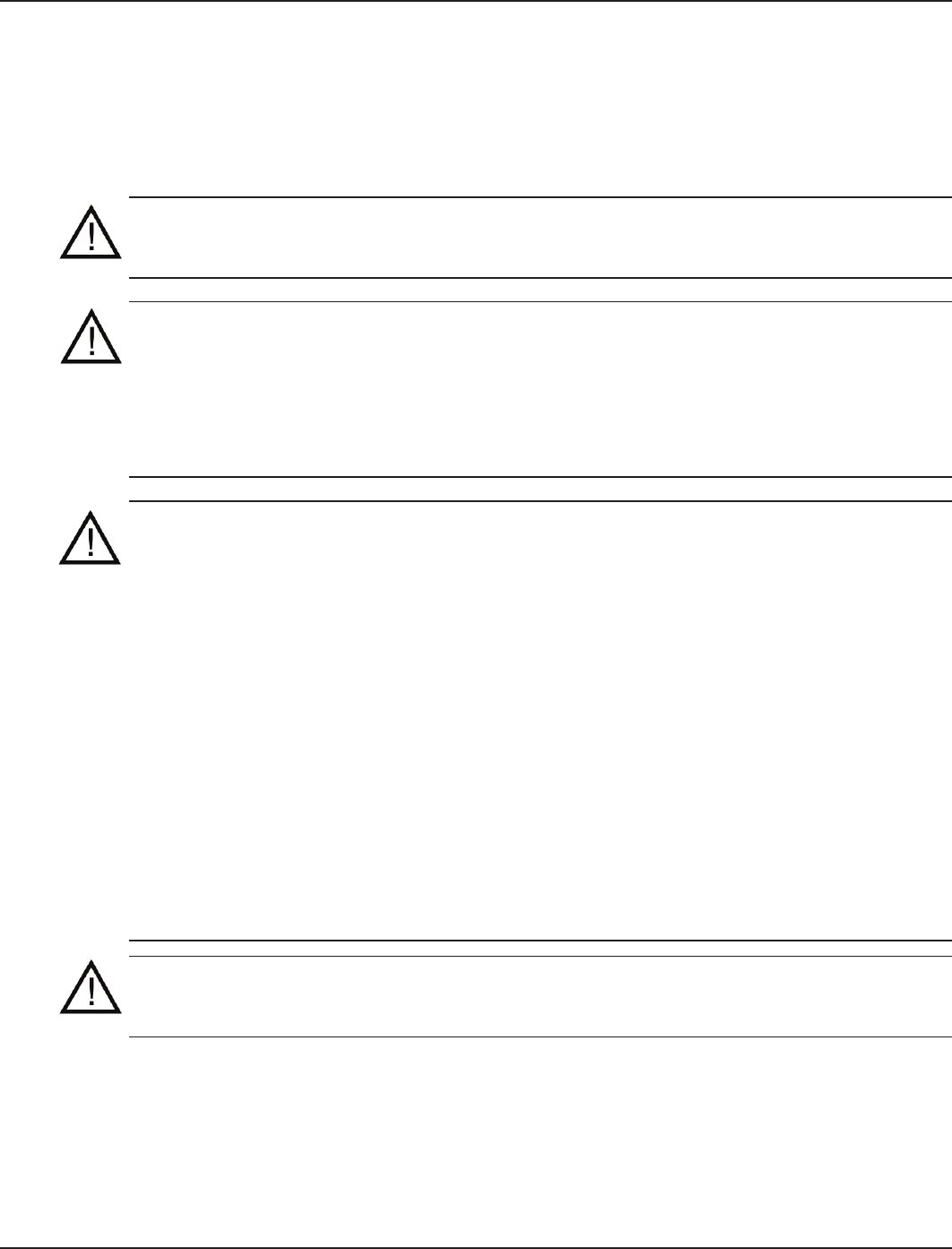
The standard conguration for the I-Wave Pool/Spa Wireless Control System conguration is
shown in Figure 1-1. You can order individual components for a custom conguration or system
as indicated.
•
•
•
•
•
Figure 1-1Figure 1-1
Valve/Pump Switch (P4243ME), can control
up to 2 different pool/spa circuits and up
to 3 valve actuators. Can also be ordered
separately.
Valve/Pump Switch (P4243ME), can control
up to 2 different pool/spa circuits and up
to 3 valve actuators. Can also be ordered
separately.
Hand-Held Transceiver (PE950).
Up to 5 units can be used with an
I-Wave system. Additional units
can be ordered separately.
Hand-Held Transceiver (PE950).
Up to 5 units can be used with an
I-Wave system. Additional units
can be ordered separately.
Transceiver Repeater Module (HA04C)
plugs into electric outlet to eliminate
wireless interference and dead spots.
Rated for indoor or outdoor use.
Additional units can be ordered.
Transceiver Repeater Module (HA04C)
plugs into electric outlet to eliminate
wireless interference and dead spots.
Rated for indoor or outdoor use.
Additional units can be ordered.
Panel-Mounted Transceiver (PE650).
Removable anntenna (0000000)
can be ordered separately
Panel-Mounted Transceiver (PE650).
Removable anntenna (0000000)
can be ordered separately
I-Wave Steel Outdoor Enclosure
(PE40000), weatherproof, and with
plenty of room to add additional
sawitch mechanism if desirable.
Can also be ordered separately
by installers who want to create
a non-standard system from
individual components.
I-Wave Steel Outdoor Enclosure
(PE40000), weatherproof, and with
plenty of room to add additional
sawitch mechanism if desirable.
Can also be ordered separately
by installers who want to create
a non-standard system from
individual components.
Three-Circuit Clock (P1353ME)
offers timer capability and can
control up to 3 pool/spa circuits.
Offers five pre-programmed
configuration modes.
Three-Circuit Clock (P1353ME)
offers timer capability and can
control up to 3 pool/spa circuits.
Offers five pre-programmed
configuration modes.
24-volt Valve Actuators (PE24VA)
provide reliable control of 2-way and
3-way diverter valves. (2 are included,
additional units can be ordered)
24-volt Valve Actuators (PE24VA)
provide reliable control of 2-way and
3-way diverter valves. (2 are included,
additional units can be ordered)
One: System Overview 7
Providing a brighter solution.™
The standard system is shipped with snap-in mechanisms in place inside the enclosure, the panel
mount transceiver attached to the top of the enclosure, with antenna to be attached. Components
are already interconnected and are ready for wiring. System model numbers are designed to
make sure the installation meets local code as follows:
PE45343RC — the basic radio-controlled system.
PE45343RCT1 — a special version with a 100 watt transformer for 12-Volt underwater
lighting, where required by local code. The 100-watt transformer (PA117) can also be
ordered separately for installation into standard model PE45343RC.
PE45343RCT3 — a special version with a 300 watt transformer for 12-Volt underwater
lighting, where required by local code. The 300-watt transformer (PA116) can also be
ordered separately for installation into standard model PE45343RC.
You can order most system components individually to assemble a custom I-Wave system as
desired.
Additional Detail on Key Components
Three-Circuit Clock (P1353ME)
Designed for aftermarket and retrot applications, the P1353ME has the
ability to program up to three different circuits. Choose between ve
pre-programmed modes of operation, which include single speed pump
or 2-speed pump/cleaner pump combinations. In addition, programmed
modes that include auxiliaries can control pumps up to 3 HP as well as
underwater, garden, and/or fountain lighting. Countdown and Override
features allow cycle interruptions when pool/spa service is required.
All timing and protection, associated with lter pump/cleaner pump
combinations and two-speed pumps, has already been integrated into
the software. This mechanism can also be installed into almost any
Intermatic enclosure.
120 or 208-240 Volt Input Voltage
Memory Back-Up
Heater Protection (Fireman Switch)
LCD Readout
Shipping Weight — 3 lbs. (1.4 kg)
Agency Approval — CSA/C-US
•
•
•
•
•
•
CONTACT RATINGS – EACH CIRCUIT, ALL MODES
20A Resistive, 120/240 VAC., 50/60 Hz
20A FLA@120 VAC, 96A LRA@120 VAC, 50/60 Hz
17A FLA@240 VAC, 80A LRA@120 VAC, 50/60 Hz
5 Amps Tungsten, 120/240 VAC, 50/60 Hz
5 Amps Ballast, 120/240 VAC, 50/60 Hz
•
•
•
•
•
•
•
•
8 I-Wave Installation Guide
Copyright © 2006 Intermatic, Inc.
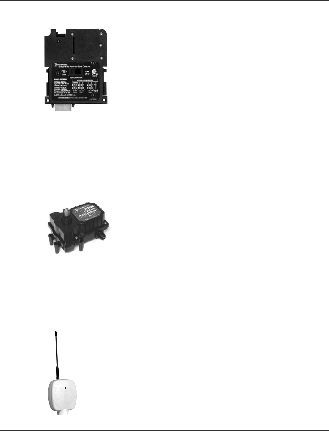
Valve/Pump Switch (P42343ME)
Designed for aftermarket and retrot applications, the P4243ME is
most suited for controlling up to two different circuits associated with
pool/spa combinations but can also be used to control all the equipment
typically needed in connection with water features, water gardening,
solar heating, and other similar applications. This unit snaps into almost
any Intermatic enclosure and features two 3HP double pole relays,
one of which can be controlled by an external timer, 24 volt supply for
up to three valve actuators, automatic HIGH/LOW water temperature
selector, heater connection circuit, and push button control for each
load with indicator lights on the face of the control. In addition, the unit
has connections for a hard-wired or wireless remote and a master switch
controller.
120 or 208-240 Volt Input Voltage
Controls up to three valve actuators
Switches heater thermostat
Remote control capabilities
Shipping Weight — 3 lbs. (1.4 kg)
Agency Approval — CSA/C-US
•
•
•
•
•
•
CONTACT RATINGS – EACH CIRCUIT
17A Resistive, 120/240 VAC., 50/60 Hz
1.5 HP @ 120 VAC., 50/60 Hz
3.0 HP @ 240 VAC., 50/60 Hz
10 Amp Tungsten, 120/240 VAC, 50/60 Hz
•
•
•
•
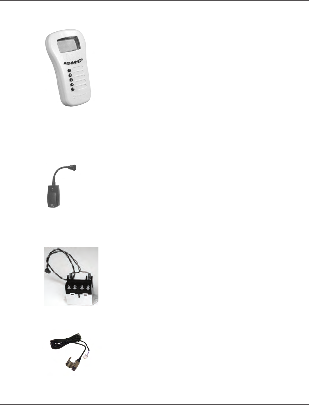
24-Volt Valve Actuator (PE24VA)
Designed with quality in mind, Intermatic’s 24-volt valve actuators
provide reliable control of 2-way and 3-way diverter valves for pool/
spa combinations and water features. The water ow can be altered
for specic applications through the adjustable cam, which rotates
diverter valves to multiple degree settings. The cam settings can be
easily adjusted by simply removing the lid. These valve actuators are
compatible with all pool/spa valves currently offered in the industry and
will retrot into all pool/spa control systems.
24VAC Input Voltage
Automates compatible diverter
valves for pool/spa combos
Adjustable cam rotates diverter
valves to multiple degree settings
•
•
•
Designed to operate most 2-way and 3-way diverter
valves
Shipping Weight - 3 lbs. (1.4 kg)
Agency Approval - CSA/C-US
•
•
•
Panel-Mounted Transceiver (PE650) and Antenna (0000000)
The main function of the Panel-Mounted Transceiver is to take commands from
the Wireless Hand-Held Transceiver and hand them off to two mechanisms
(P1353ME and/or P4243ME) in the I-Wave Enclosure box. This unit can control:
One P1353ME unit and one P4243ME unit
Two P1353ME units
Two P4243ME units
In cases where the two devices are too far apart for direct communication, a
Transceiver Repeater Module (HA04C) will relay commands between the two
devices. Shown here with its removable antenna (0000000).
•
•
•
One: System Overview 9
Providing a brighter solution.™
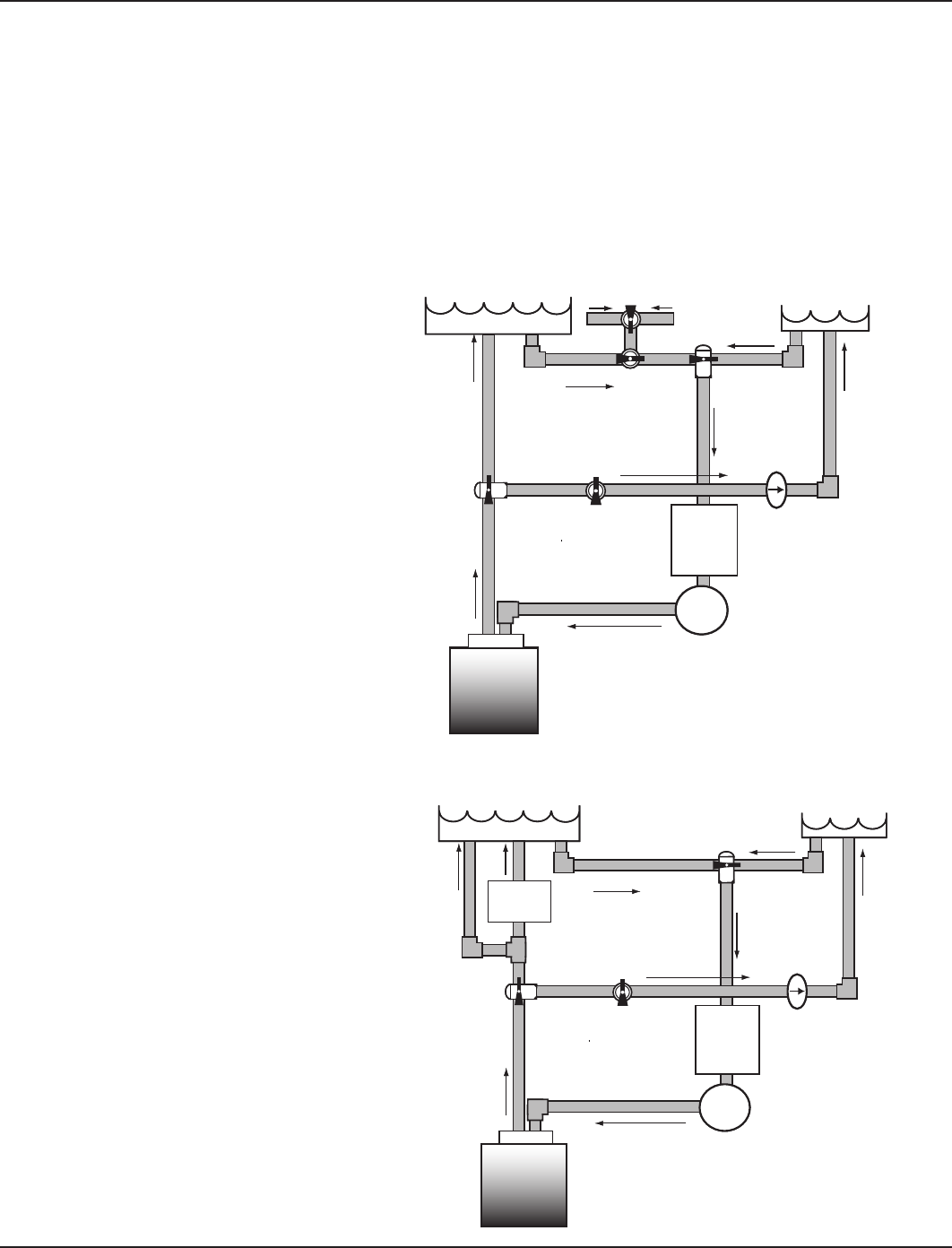
Wireless Hand-Held Transceiver (PE950)
The main function of the Wireless-Hand-Held Transceiver is to transmit user
commands to the Panel Mount Transceiver. The device can control up to ve
loads, typically:
The three loads in the Three-Circuit Clock
The two relays in the Valve/Pump Switch, usually water temperature
controls for pool/spa
The actuators that switch between pool and spa
The unit oats if thrown in the pool or spa, is water-submersible, shock
resistant, and requires three (3) AA batteries (supplied). Expected battery life
is about one year in typical use.
The Wireless Hand-Held Transceiver can only communicate with the Panel-Mounted Transceiver
and Transceiver Repeater Module, and is compatible with no other hardware. In addition, when
the components of a specic system are linked together into a network, communication with
another neighboring system cannot occur.
Transceiver Repeater Module
The Transceiver Repeater Modules (HA04C) ensure that no problems in
reception occur between the Hand-Held Controller(s) and the Panel-Mounted
Transceiver. Reception is affected by distance (about 100 feet, direct line of sight)
and by physical obstacles (like brick walls or structures). However, by plugging
in a Transceiver Repeater Module where necessary, long distances or physical
obstructions can be overcome.
The I-Wave System includes one Transceiver Repeater Module. Additional units can be odered
from Intermatic.
OMRON Relay Assembly (143T145A)
There are two OMRON Relay Assemblies (143T145A) in the Valve/Pump
Switch Mechanism ( ) which switch either 120V or 240V loads. These
relays are replaceable and can be ordered separately.
Water Temperature Sensor (178PE4)
The Intermatic Water Sensor (178PE4) monitors both pool and spa water
temperature, depending on the position of the diverter valves. Installation
is necessary for the thermostatic control to work. The sensor can be
ordered separately.
•
•
•
CONTACT RATINGS – EACH CIRCUIT
17A Resistive, 120/240 VAC., 50/60 Hz
1.5 HP @ 120 VAC., 50/60 Hz
3.0 HP @ 240 VAC., 50/60 Hz
10 Amp Tungsten, 120/240 VAC, 50/60 Hz
•
•
•
•
CONTACT RATINGS – EACH CIRCUIT
17A Resistive, 120/240 VAC., 50/60 Hz
1.5 HP @ 120 VAC., 50/60 Hz
3.0 HP @ 240 VAC., 50/60 Hz
10 Amp Tungsten, 120/240 VAC, 50/60 Hz
•
•
•
•

10 I-Wave Installation Guide
Copyright © 2006 Intermatic, Inc.
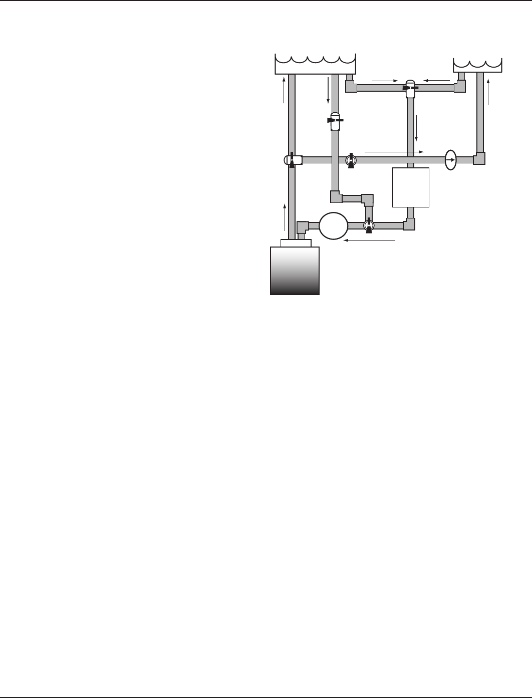
Optional — Three-Button Wired Remote Control (133PE1484A)
The Three-Button Wired Remote Control (133PE1484A) plugs into either the
Three-Circuit Clock (PE1353ME) or Valve/Pump Switch (PE4243ME).
When installed as part of a system, it replaces the wireless method of controlling
the three circuits within the mechanism. For more information, refer to Installing a
Wired Remote Connection in Section 4. The Three-Button Wired Remote Control
must be installed where a third mechanism is needed in the enclosure box, since the Wireless
Hand-Held Transceiver can only control two mechanisms.
Optional — Freeze (Air Temperature) Sensor (178PA28A)
Add the Intermatic Freeze or Air Temperature Sensor (178PA28A) to installations
where below-freezing outdoor temperatures are a concern. Programming
information to incorporate the sensor is provided on page 34.
Need Picture
Two: Plumbing and Wiring Examples 11
Providing a brighter solution.™
Section 2:
Plumbing Examples
The following diagrams show several plumbing and wiring examples of installations for pool and
spa that share a single lter pump, lter, and heater. If you are installing a pool only or spa only,
these diagrams will not apply.
For Pool and Spa
Combo Installations
For Booster Pump Pool
Cleaner Installations
Pool Spa
Filter
Check Valve
Spa Make-up Filter
Pump
Intake
Return Return
Intake
Skimmers
Heater
Pool Spa
Filter
Check Valve
Spa Make-up Filter
Pump
Intake
Return Return
Intake
Skimmers
Heater
Pool Spa
Filter
Check Valve
Spa Make-up Filter
Pump
Intake
Return
Return
Intake
Heater
Booster
Pump
Pool Spa
Filter
Check Valve
Spa Make-up Filter
Pump
Intake
Return
Return
Intake
Heater
Booster
Pump
12 I-Wave Installation Guide
Copyright © 2006 Intermatic, Inc.
For Non-Booster Pump
Pool Cleaner Installations
Pool Spa
Filter
Check Valve
Spa
Make-up
Filter
Pump
Intake
Return Return
Intake
Heater
Pool Spa
Filter
Check Valve
Spa
Make-up
Filter
Pump
Intake
Return Return
Intake
Heater
Three: Control Center Installation 13
Providing a brighter solution.™
Section 3:
Control Center Installation
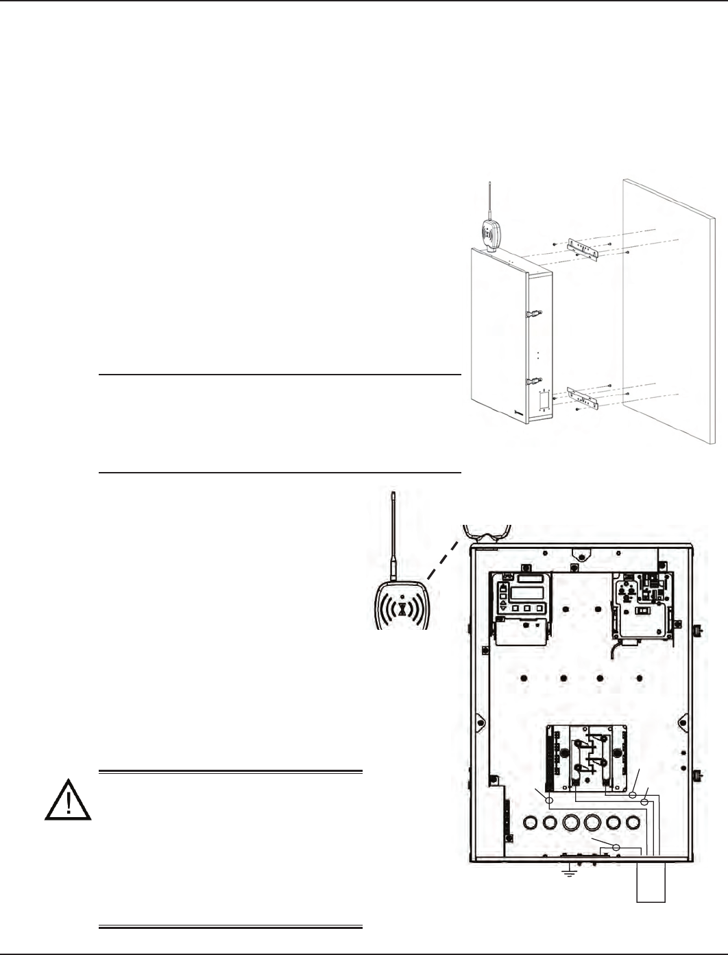
Mounting the Control Center
Special code requirements apply to your I-Wave
Control System. To ensure safe installation, please
follow all applicable national state, and local codes
when installing the Control Center.
Locate your Control Center near the pool/spa
equipment pad at least ve feet or more away from
either the pool or spa equipment and at least ve feet
off the ground.
Mounting brackets have been provided to assist you in
your installation.
NOTE: The Control Center is not to be considered
as suitable for use as Service Equipment. Therefore,
it is required to have the appropriate means of
disconnection, circuit isolation, and/or branch circuit
protection installed at the Main Power Panel.
Wiring the System Power
Run wire from the Main Power Panel
to your Control Center and connect the
leads to the Control Center Breaker Base.
See detail in Figure 3-2 at the right.
The breaker base of your Control Center
is capable of handling up to 125 amps.
You must comply with the applicable
local codes and use the proper gauge
wiring from your Main Power panel to
your control center breaker base. The
proper gauge wire will be determined by
the length of wire required and the 125
Max Amp rating.
WARNING: Potentially high
voltages in the Control Center
can create dangerous electrical
hazards, possibly causing death,
serious injury, or property damage.
Turn off the Main Power to the
Control Center to disconnect or
service the I-Wave Control Center.
Figure 3-1Figure 3-1
Earth Ground
From Main
Power
White
(neu)
Black
Red
Ground
Earth Ground
From Main
Power
White
(neu)
Black
Red
Ground
Figure 3-2Figure 3-2

14 I-Wave Installation Guide
Copyright © 2006 Intermatic, Inc.
Bonding the Control Center
Some state local codes require bonding the control center
to the bonding grid. If this is required, install a bonding lug
(130PA1362) to the Control Center enclosure and connect a
#8 solid copper core wire, to an approved earth ground, (i.e.
approved ground stake, or conducting metal water pipe buried
to a sufcient depth, etc.). See detail in Figure 3-3 at the right.
Wiring the Individual Equipment
Each piece of pool or spa equipment requires its own high voltage relay and associated circuit
breaker branch protection. Each circuit breaker should be sized according to your load and the
appropriate local codes.
The I-Wave Control System consists of two Intermatic snap-in mechanisms:
P1353ME — with three timed circuits each comprised of three SPST relays
P4243ME — with two on-demand circuits comprised of two DPST relays
Even though the three circuit clock can easily handle on-demand circuits, any equipment that
requires programmed ON/OFF times should be wired to the three-circuit P1353ME mechanism
(i.e., lter pumps, booster pumps, etc.). On-demand equipment (i.e., blowers, lights, etc.) should
be wired to the P4243ME valve-controller mechanism. This practice will maximize your control
capabilities.
All circuits are independent contacts. Therefore you can mix and match 120-Volt and 240-Volt
loads within each mechanism. Refer to the following illustrations for sample wiring diagrams.
•
•
Part Number
130PA1362
Part Number
130PA1362
Figure 3-3Figure 3-3
Three: Control Center Installation 15
Providing a brighter solution.™
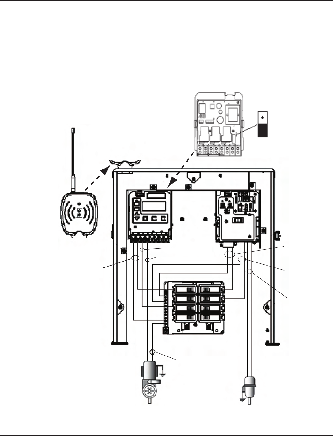
If Wiring 120-Volt Loads:
For safety purposes, the factory default setting for the source voltage of a P1353ME
mechanism is for 240 Volts.
For 120-Volt installations, be sure you set the Source Voltage Selection Jumper on the back of
the Three-Circuit Clock mechanism (P1353ME) for 120 Volts before you begin wiring.
For more information, see Identifying Connections and Selecting Proper Input Voltage on
page 24.
•
•
•
If using 120V source voltage,
set voltage selector jumper
on back of P1353ME clock
mechanism to 120V
Breaker
Panel
Filter Pump
(120 VAC)
Neutral
Blower
(120 VAC)
Blk/Wht
120 VAC
Blk/Red
Line
Blu/Yel
Load
Blk/Wht
120 VAC
120V 240V
Blk (line)
Blk (load)
(P1353ME)
If using 120V source voltage,
set voltage selector jumper
on back of P1353ME clock
mechanism to 120V
Breaker
Panel
Filter Pump
(120 VAC)
Neutral
Blower
(120 VAC)
Blk/Wht
120 VAC
Blk/Red
Line
Blu/Yel
Load
Blk/Wht
120 VAC
120V 240V
Blk (line)
Blk (load)
(P1353ME)
Figure 3-4Figure 3-4
16 I-Wave Installation Guide
Copyright © 2006 Intermatic, Inc.
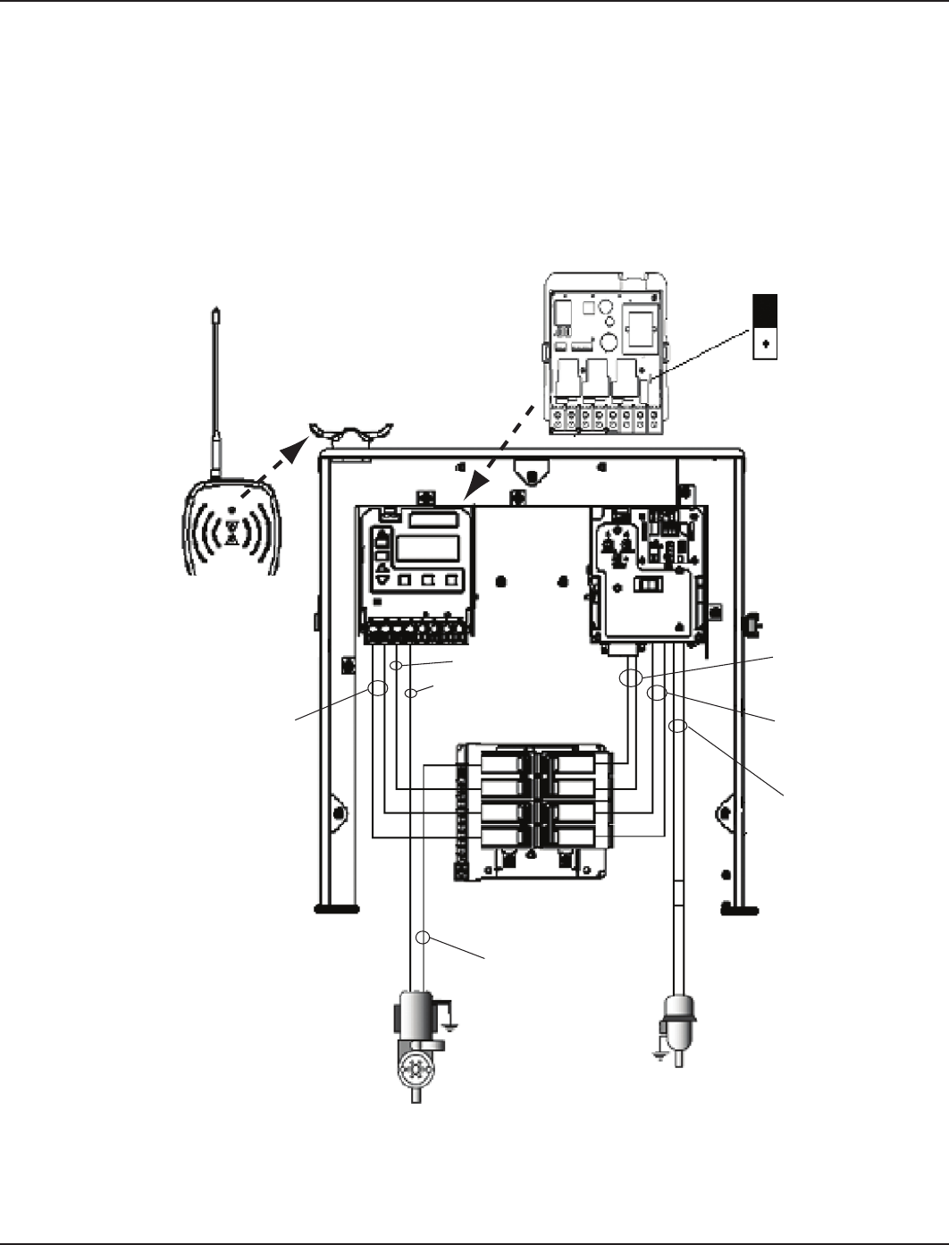
If Wiring 240-Volt Loads:
For safety purposes, the factory default setting for the source voltage of a P1353ME
mechanism is for 240 Volts.
The Source Voltage Selection Jumper on the back of the Three-Circuit Clock mechanism
(P1353ME) will already be correctly set, ready for you to begin wiring.
For more information, see Identifying Connections and Selecting Proper Input Voltage on
page 24.
•
•
•
If using 240V source voltage,
set voltage selector jumper
on back of P1353ME clock
mechanism to 240V
Breaker
Panel
Filter Pump
(240 VAC)
Red
Blower
(240 VAC)
Blk/Org
240 VAC
Blk/Red
Line
Blu/Yel
Load
Blk/Red
240 VAC
120V 240V
Blk (line)
Blk (load)
(P1353ME)
If using 240V source voltage,
set voltage selector jumper
on back of P1353ME clock
mechanism to 240V
Breaker
Panel
Filter Pump
(240 VAC)
Red
Blower
(240 VAC)
Blk/Org
240 VAC
Blk/Red
Line
Blu/Yel
Load
Blk/Red
240 VAC
120V 240V
Blk (line)
Blk (load)
(P1353ME)
Figure 3-5Figure 3-5
Three: Control Center Installation 17
Providing a brighter solution.™
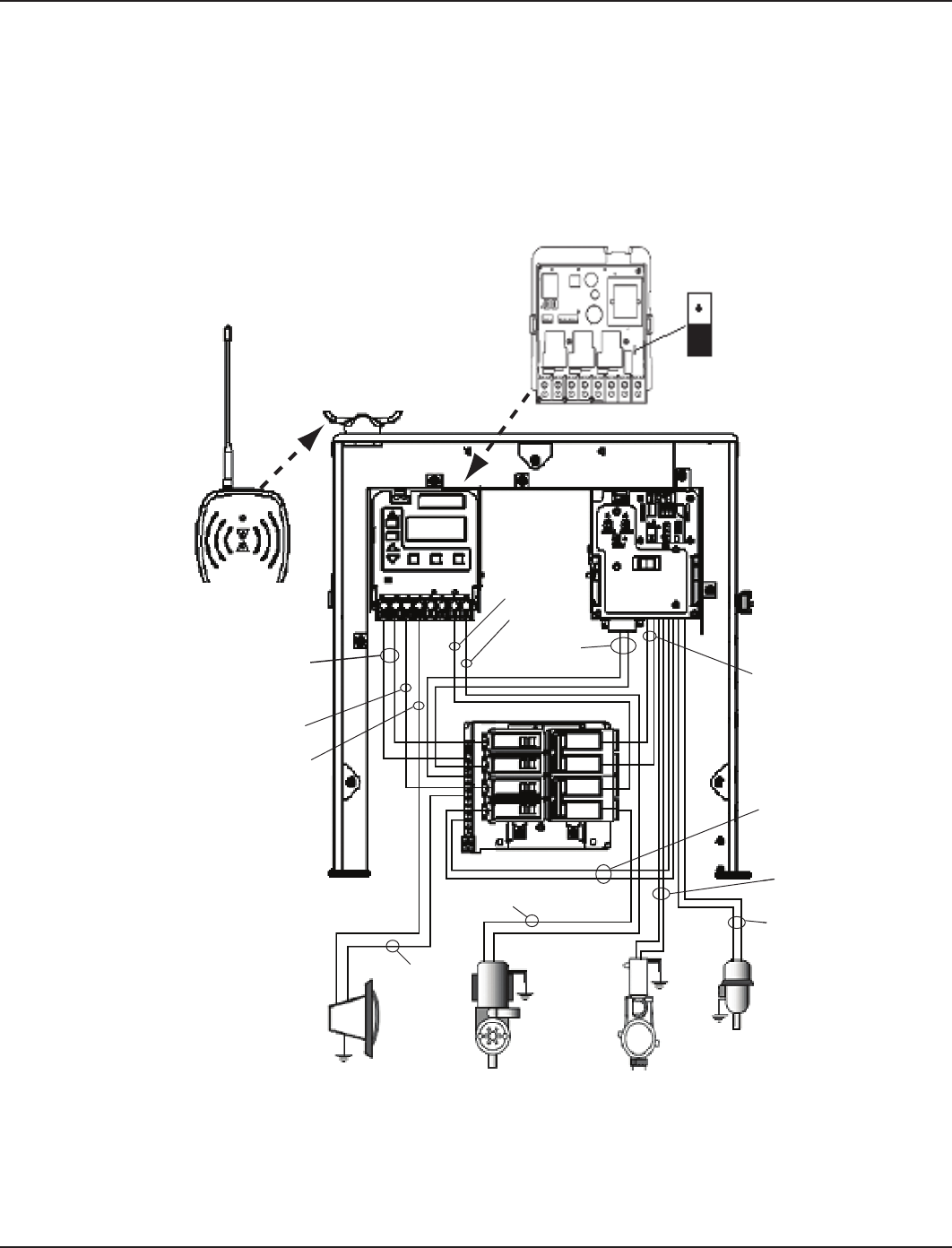
If Wiring Combination 120- and 240-Volt Loads:
For combination 120- and 240-Volt loads, change the factory default setting of the Source
Voltage Selection Jumper on the back of the Three-Circuit Clock mechanism (P1353ME) from
its factory default setting to 120 Volts.
For more information, see Identifying Connections and Selecting Proper Input Voltage on
page 24.
•
•
For combo 120- 240V loads,
set source voltage selector
jumper on back of P1353ME
clock mechanism to 120V
Filter Pump
(120 VAC)
Neu
Blower
(120 VAC)
Blk/Wht
120 VAC Blk/Red
Line
Blu/Yel
Load
Blk/Wht
120 VAC
120V 240V
Blk (line)
Blk (load)
(P1353ME)
Blk (load)
Blk (line)
Vio/Org
Line
Blu/Gry
Load
Jet Pump
(240 VAC)
Light
(120 VAC)
Red
Figure 3-6Figure 3-6
18 I-Wave Installation Guide
Copyright © 2006 Intermatic, Inc.
Wiring Underwater Lights
CAUTION: A Ground Fault Circuit Interrupter (GFCI) must be provided for high
voltage pool/spa lights. Do not use a GFCI circuit breaker.
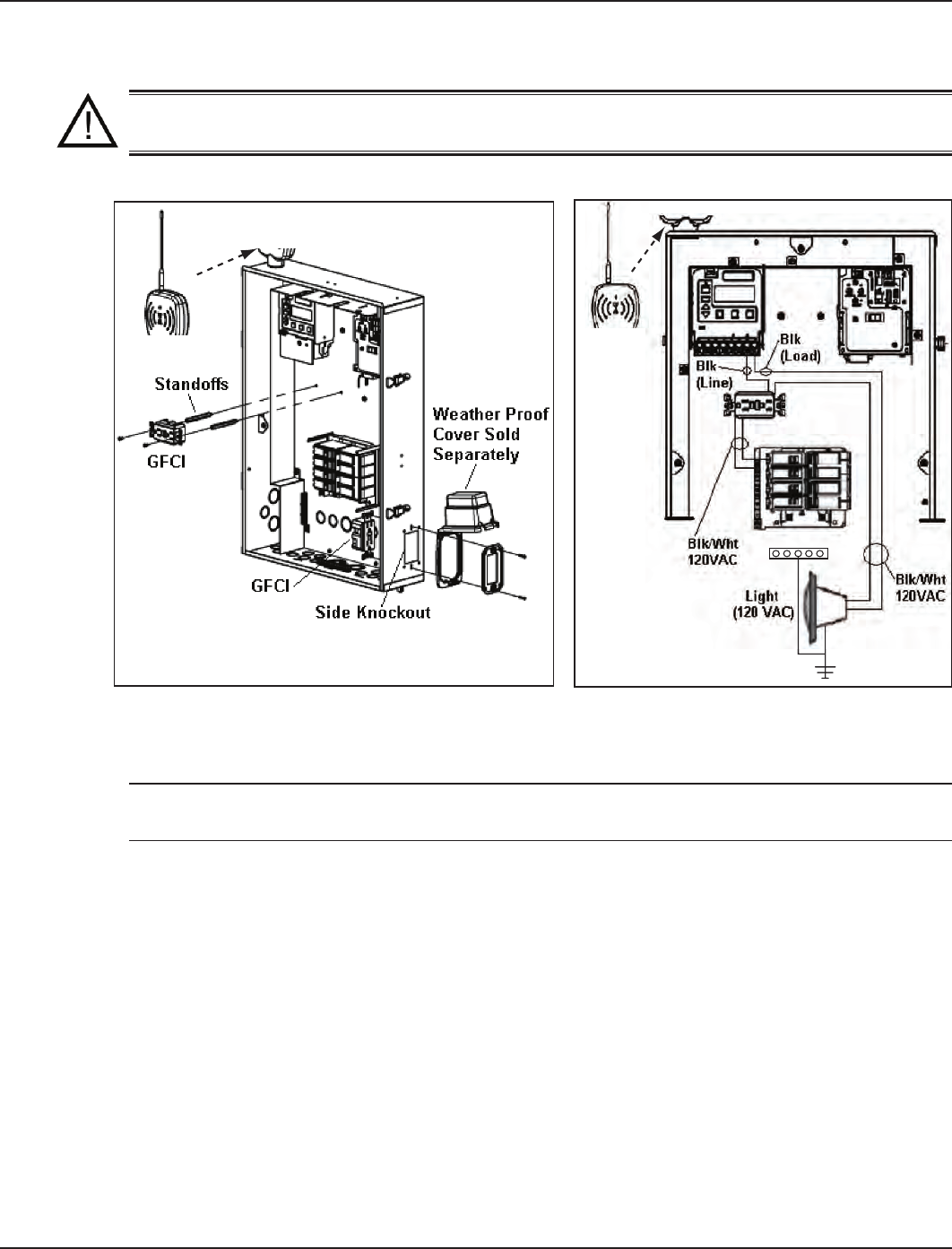
High-Voltage Underwater Lights
The I-Wave Control Center comes equipped with two décor knockouts on the dead front and
one side knockout for installation of GFCI receptacles. (See Figure 3-7).
NOTE: If using the décor knockouts to install a GFCI, you must use the standoffs provided with
the Control Center to mount your GFCI.
Install a GFCI receptacle and connect the neutral and hot wire, from the circuit breaker, to the
LINE side of the GFCI. (See Figure 3-8).
Connect the neutral (white wire) to the GFCI.
Connect the hot (black wire) as follows:
To the LOAD side of clock,
Then out the LINE side of the clock to the LOAD side of the GFCI. (See Figure 3-8.)
Connect the ground (green wire) from the light to the grounding bar inside the Control Center.
1.
2.
3.
a.
b.
4.
(0000000)(0000000)
Figure 3-7 Figure 3-8 Figure 3-7 Figure 3-8
Three: Control Center Installation 19
Providing a brighter solution.™
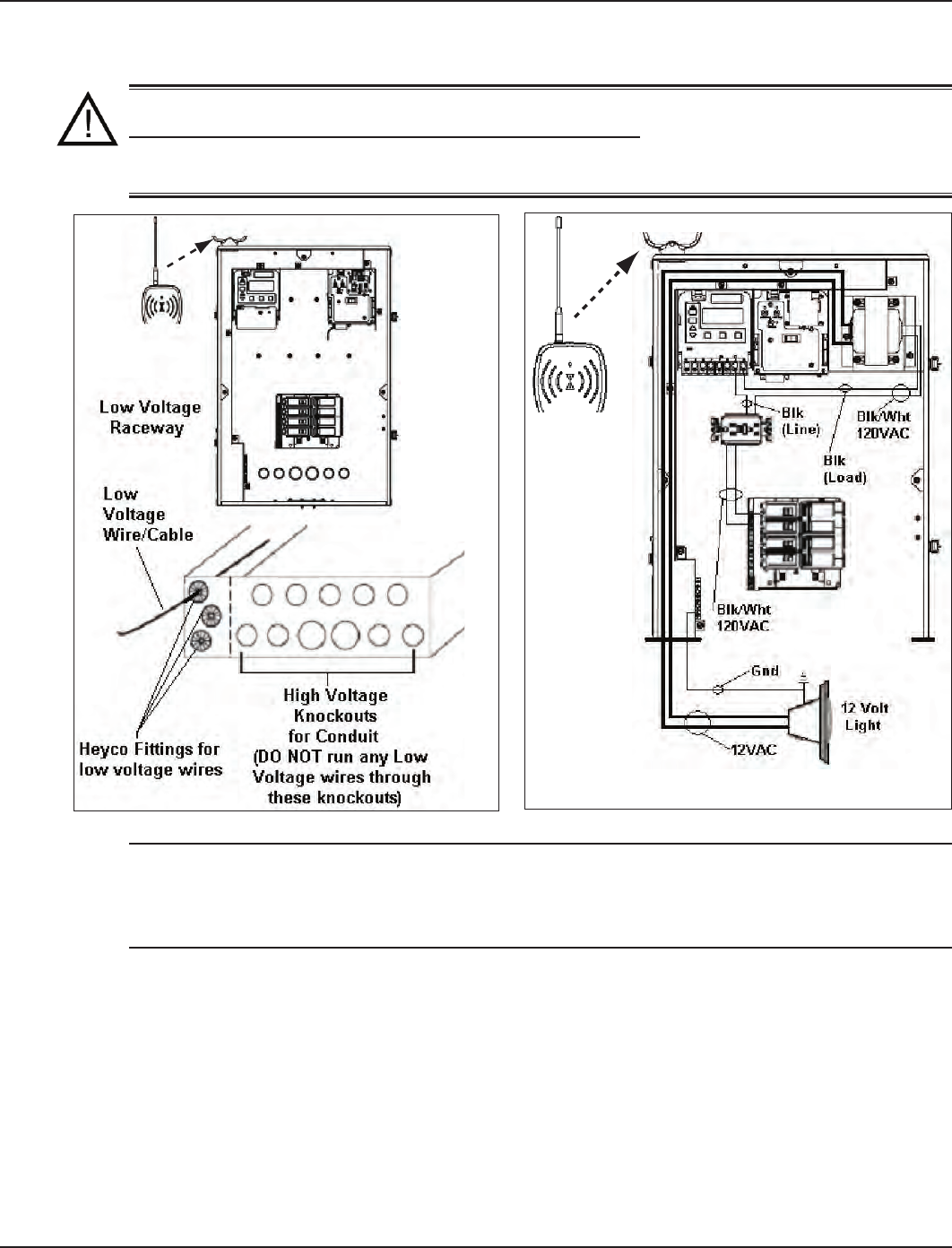
Low-Voltage Underwater Lights
CAUTION: Your I-Wave Control Center is equipped with a Low Voltage Raceway.
You must use this raceway for all low voltage wiring, including the 12 Volt wires
from the transformer. You cannot mix high and low voltages in the high voltage
compartment.
NOTE: If you require a low voltage transformer, you should order system model PE45343RCT1
(with a 100 watt transformer) or PE45343RCT3 (with a 300-watt transformer). Alternatively, you
can order a 300-watt PA116 or 100-watt PA117 12V transformer kit to mount in the standard
system model PE45343RC. (See Figure 3-9.)
If required by local code, install a GFCI receptacle and connect the neutral and hot wire, from
the circuit breaker, to the LINE side of the GFCI. (See Figure 3-10.)
Connect the lite to the secondary side of the transformer.
Connect the neutral side of the transformer to the load side of the GFCI.
Connect the hot as follows:
To the LOAD side of clock,
Then out the LINE side of the clock to the LOAD side of the GFCI. (See Figure 3-10.)
Connect the ground (green wire) from the light to the grounding bar inside the Control Center.
1.
2.
3.
4.
a.
b.
5.
Figure 3-9 Figure 3-10 Figure 3-9 Figure 3-10
20 I-Wave Installation Guide
Copyright © 2006 Intermatic, Inc.
Low-Voltage Wiring
CAUTION: Your I-Wave Control Center is equipped with a Low Voltage Raceway.
You must use this raceway for all low voltage wiring, including the 12 Volt wires
from the transformer. You cannot mix high and low voltages in the high voltage
compartment.
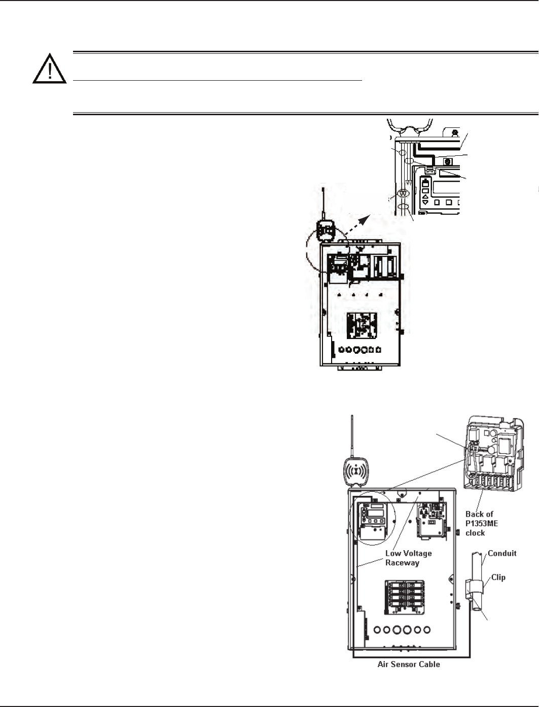
Water Temperature Sensor
The I-Wave Control System comes equipped
with a Water Temperature Sensor. This sensor is
needed to monitor and maintain both the pool
and spa water temperature depending on the
position of the diverter valves. It needs to be
installed in order for the thermostat control to
work. Power needs to be disconnected when
connecting the temp sensor. Only an Intermatic
Sensor will work with this controller. Follow
the directions below to install and mount your
water temperature sensor. Refer to page 43 For
programming instructions.
Drill a 3/8” hole in the pipe between the
lter pump and lter and install the Water
Temperature Sensor with hose clamp (not
provided). Ensure the O-ring is in place.
Run the wire to the Control Center, through
the low voltage raceway. Connect both wires
to the Panel Mount Receiver. (See Figure 3-11.)
Freeze (Air Temperature) Sensor
The I-Wave Control System uses an optional Air
Temperature Sensor (178PA28A) for measuring air
temperature and implementing the Freeze Protection
Circuit—necessary for the freeze protection circuit and
programming to work. Power must be disconnected
when connecting the freeze sensor. Only an Intermatic
Sensor will work with this controller. Refer to page 34
for programming information.
Install the Air Temperature Sensor outside the
Control Center, preferably onto a piece of conduit at
or near your equipment pad. Use the clip provided
with the sensor. Do not install in direct sunlight or
around motors or other heat sources.
Run the wire to the Control Center through the low
voltage raceway. Connect Air Sensor directly to the
back of the three-circuit clock mechanism. (See
Figure 3-12.)
1.
2.
1.
2.
Fireman’s Switch Wires
(Brown/Brown)
Water Temp Wires
(Black/White)
Make
connection
with
connectors
provided
Cable to P1353ME
Cable to P4232ME
Wires from
Water Temp Sensor
(Black/White)
(178PE4)
Fireman’s Switch Wires
(Brown/Brown)
Water Temp Wires
(Black/White)
Make
connection
with
connectors
provided
Cable to P1353ME
Cable to P4232ME
Wires from
Water Temp Sensor
(Black/White)
(178PE4)
Figure 3-11Figure 3-11
Remove clock and connect
Freeze (Air Temp) Sensor
(178PA28A) here
Freeze (Air
Temp) Sensor
(178PA28A)
Remove clock and connect
Freeze (Air Temp) Sensor
(178PA28A) here
Freeze (Air
Temp) Sensor
(178PA28A)
Figure 3-12Figure 3-12
Three: Control Center Installation 21
Providing a brighter solution.™
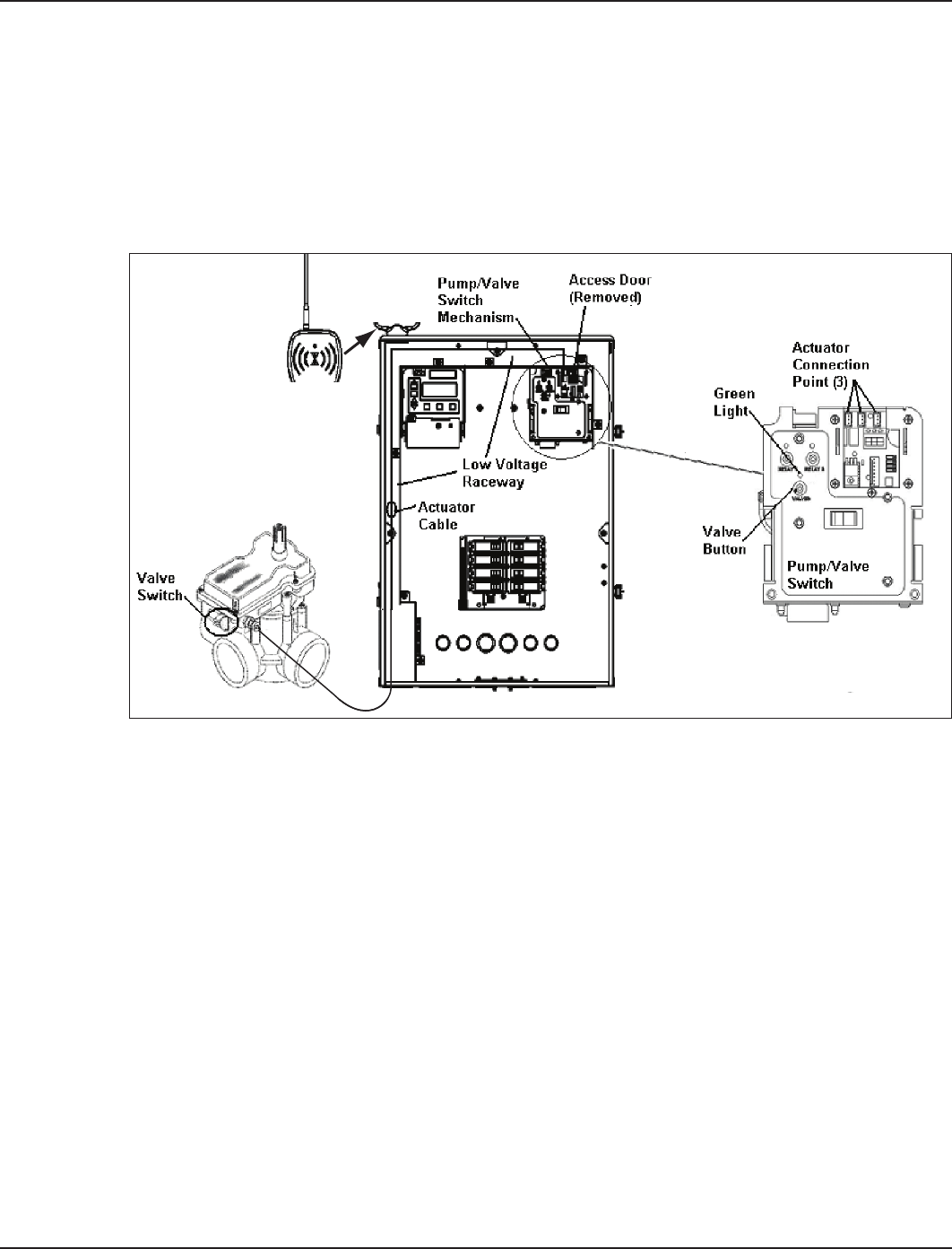
Motorized Valve Actuator Connection and Synchronizing
The I-Wave Control System is capable of controlling up to three Motorized Valve Actuators. Two
Intermatic Motorized Valve Actuators (PE24VA) are included with your I-Wave system. Contact
Intermatic Customer Service to order additional actuators.
The actuators must be installed to automatically rotate your valves between pool and spa
plumbing. Power must be disconnected when connecting the actuator connectors to your I-Wave
Control Center. Refer to the directions below prior to installing your PE24VA actuators. Refer to
Figure 3-13 for detail.
Remove power from the I-Wave control center.
Attach the valve actuators (PE24VA) to the water valves. (See instructions included.)
Run the actuator cable to the Control Center, and through the low voltage raceway.
Remove the access door to the Pump/Valve Switch mechanism.
Insert the three-pin connector of the motorized valve actuator to any of the three available
connectors on the Pump/Valve Switch mechanism circuit board.
Apply power to the I-Wave Control Center and synchronize the actuators as follows:
Use the Valve button located on your Pump/Valve switch to illuminate the green light
above the Valve switch. This indicates that the switch is in SPA mode.
Use the switch located on your motorized valve actuator to ensure the valves are in the
SPA position.
If either of the Actuators is positioned backwards, ip the switch on the back to reverse
position.
Verify that the Actuators are correctly synchronized with your installation.
1.
2.
3.
4.
5.
6.
a.
b.
c.
d.
Figure 3-13Figure 3-13
22 I-Wave Installation Guide
Copyright © 2006 Intermatic, Inc.
Heater Fireman Switch Connection
The I-Wave Control System is capable of controlling most heaters or heat pumps, using
thermostatic circuitry of 24 VAC or less, in the market today. Locate your heater in the following
pages and follow the instructions for proper installation with your I-Wave Control Center.
Connection to the Three-Circuit Clock
Connect the Heater Fireman switch to the Intermatic Fireman
Switch wires (tagged), located in the low-voltage raceway of the
Intermatic panel. (See Figure 3-14.)
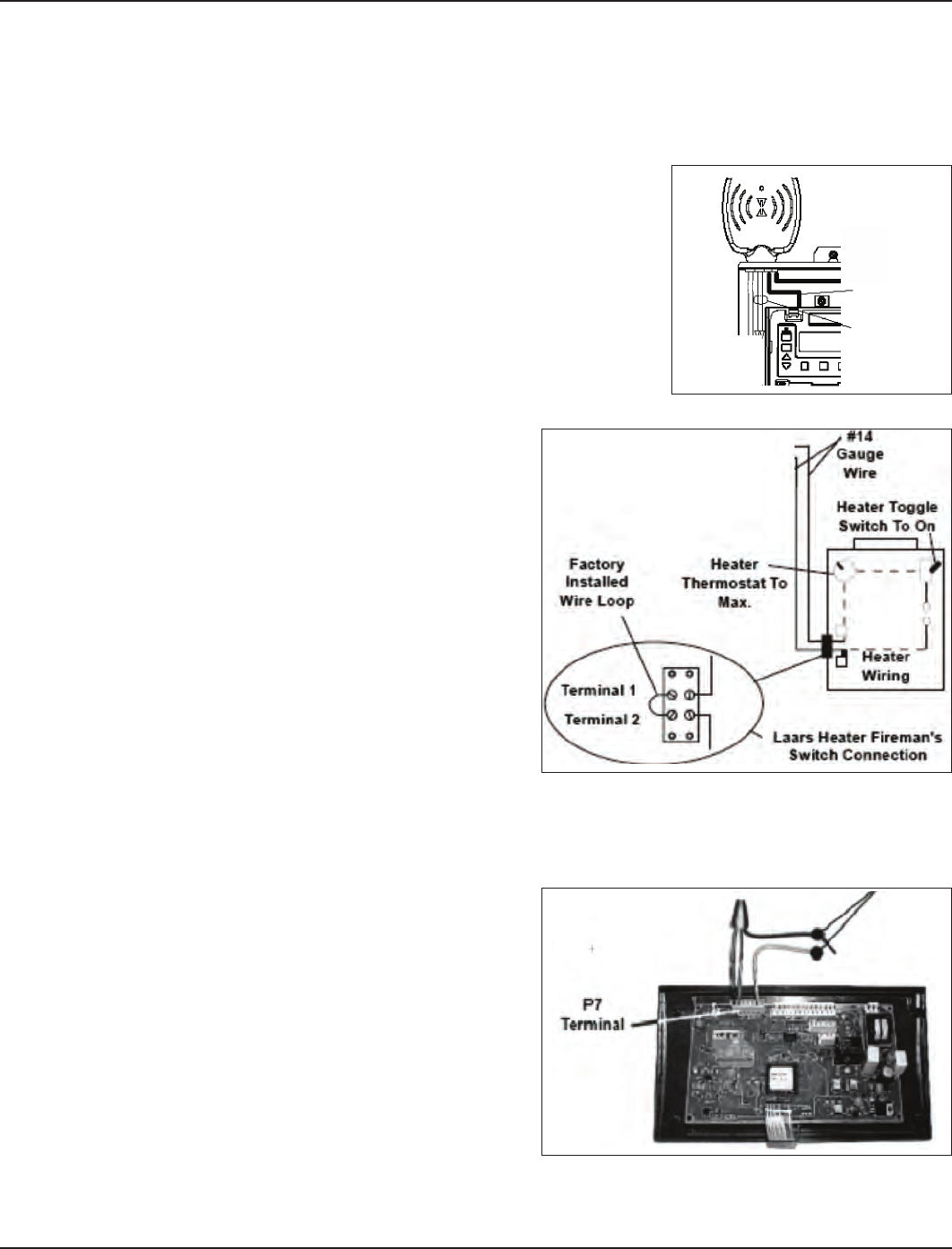
Connection for Teledyne Laars Heater
Connect two #14 gauge wires, designed for
use in hot environments, to the two black
wires, marked heater connection, on the
panel mount receiver.
Connect the other ends of the #14 gauge
wires from Step 1 to the Fireman’s Switch
terminal bar in place of the factory installed
wire loop.
Do not disconnect high limit or pressure
switches.
Turn the heater thermostat(s) to maximum
setting.
Turn the heater switch to the ON position.
For dual thermostat heaters turn switch to Spa position.
Connection for Raypak Heaters
The following connection procedure is for the two wire-one function conguration Raypak
heater.
Connect two #14 gauge wires, designed for
use in hot environments, to the two black
wires on the panel mount receiver.
Connect one end of either #14 gauge wires
from Step 1 to both the orange/black and
black/orange wires on the Raypak heater.
Connect the remaining #14 gauge wire
from Step 1 to the yellow/black wire on the
Raypak heater.
1.
2.
3.
4.
5.
1.
2.
3.
Fireman
Switch
Wires
(Blk/Wht)
Fireman
Switch
Wires
(Blk/Wht)
Figure 3-14Figure 3-14
Figure 3-15Figure 3-15
Figure 3-16Figure 3-16
Three: Control Center Installation 23
Providing a brighter solution.™
Connection for Hayward Heaters
rs
Remove heater service door on your Hayward
Heater.
Remove factory-installed wire connector between
two (2) red wires labeled “CONNECTION FOR
FIELD INSTALLED CONTROL SWITCH.” (See
Figure 3-17.)
Connect two #14 gauge wires, designed for use
in hot environments, to the two red wires. (See
Figure 3-18.)
Wire the other end to the two black wires, marked
heater connection, on the panel mount receiver in
your I-Wave Control Center.
Do not disconnect high limit or pressure switches.
Turn the heater thermostat(s) to maximum setting.
Turn the thermostat selector switch to the ON,
HIGH, or SPA position.
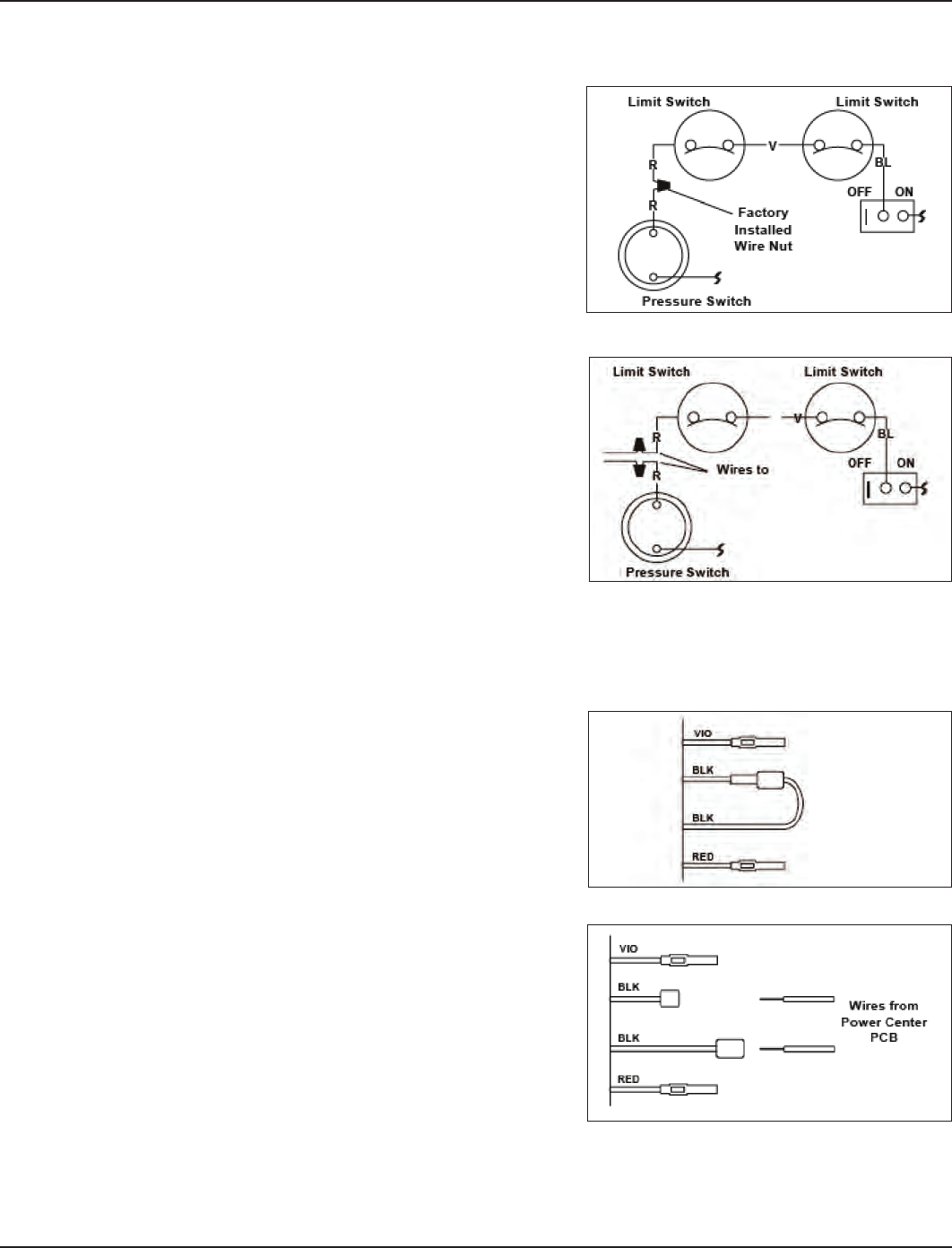
Connection for Pentair Heater
Remove heater service door on your Pentair
Heater.
Separate the black wires (common) from each
other. (See Figure 3-19.)
Connect two #14 gauge wires, designed for use in
hot environments, to the two black wires, marked
heater connection, on the panel mount receiver
in the I-Wave Control Center and attach the other
end to the two black wires on the heater. (See
Figure 3-20.)
Do not disconnect high limit or pressure switches.
Turn the heater thermostat(s) to maximum setting.
Turn the heater toggle switch on.
1.
2.
3.
4.
5.
6.
7.
1.
2.
3.
4.
5.
6.
Figure 3-17 — Wiring Before ModificationFigure 3-17 — Wiring Before Modification
Figure 3-18 — Wiring with [what??]Figure 3-18 — Wiring with [what??]
Figure 3-19 — Wiring Before ModificationFigure 3-19 — Wiring Before Modification
Figure 3-20 — Wiring with AquaLink RSFigure 3-20 — Wiring with AquaLink RS
24 I-Wave Installation Guide
Copyright © 2006 Intermatic, Inc.
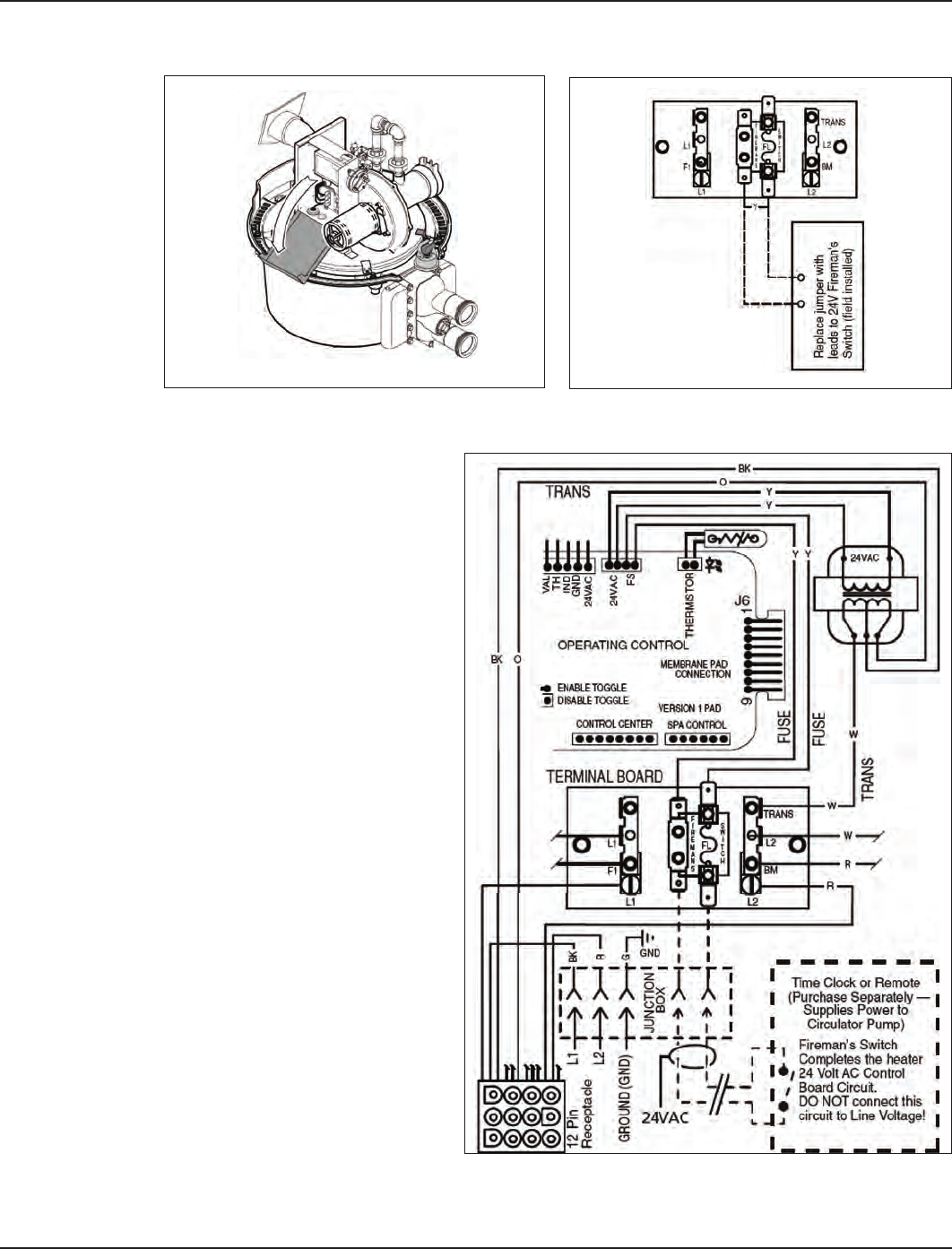
Connection for Sta-Rite Heaters
Turn off power to heater at main circuit breaker panel.
Unbolt and remove the upper jacket
halves (Refer to heater owners
manual).
Open control box cover. (See
Figure 3-21.)
Remove the factory-installed jumper
between the Fireman’s Switch
terminals. (See Figure 3-22. )
Connect two #14 gauge
wires, designed for use in hot
environments, to the two black
wires, marked heater connection,
on the panel mount receiver in the
I-Wave Control Center and attach
the other end to the two spade
terminals at the heater. You can also
cut the yellow jumper wire and wire
connect the black wires to each
yellow wire. (See Figure 3-23.)
Route the wires out through the
knockout on the bottom of the
Control Box.
Do not disconnect high limit or
pressure switches.
Turn the heater on and maximize
the temperature setting.
1.
2.
3.
4.
5.
6.
7.
8.
Figure 3-21 Figure 3-22 Figure 3-21 Figure 3-22
Figure 3-23Figure 3-23
Four: Programming the Three-Circult Clock Mechanism 25
Providing a brighter solution.™
Section 4:
Programming the Three-Circuit Clock
Mechanism
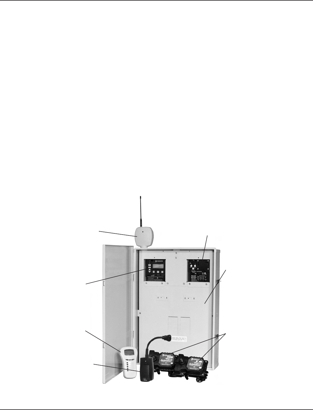
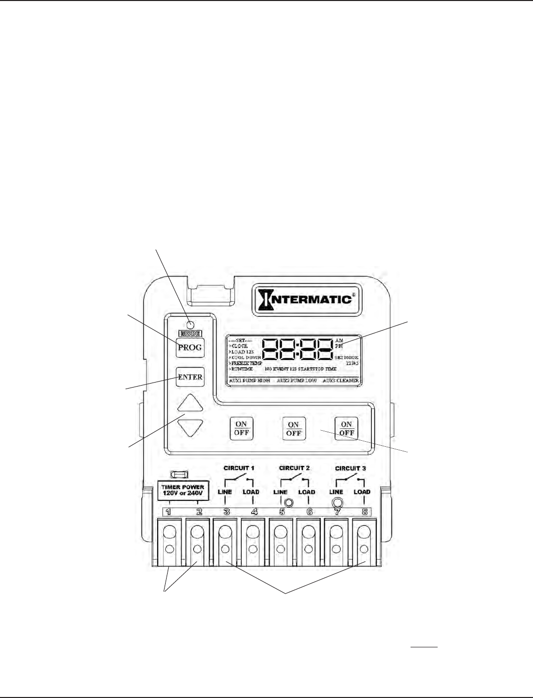
Overview of Three Circuit Clock Control Panel
The Intermatic Three-Circuit Clock Control Panel is easy to program and capable of automatically
switching loads on three circuits according to a preset 24-hour daily schedule, and providing
control over a variety of different applications. Figure 4-1 shows the front of the mechanism.
PROGRAM BUTTON—used to
enter programming mode and
access different programming
features
ENTER BUTTON—used to
save programming changes
to memory and exit
programming mode.
DISPLAY—Indicates time
of day and programming
settings during
programming mode.
ON/OFF BUTTONS—Turn
on and off circuit
functions.
CIRCUITS 1, 2, & 3—These six terminals are where you wire the equipment
source voltage and equipment load lines. You can have different source
voltages for each circuit, depending on your equipment requirements
NOTE: The three-circuit clock breaks only one leg to the load. Wire the
other leg directly from the line to the load. (Refer to the illustration on the
clock, above the terminals.)
ARROW BUTTONS—used
to increase or decrease
programming parameters
when in programming mode.
MODE BUTTON—With a small tool, press and hold this button down
for 5 seconds. Using the Up and Down arrow keys, you can select the
appropriate preprogrammed mode that matches your particular pool or spa
equipment pad configuration. Hit the ENTER key when finished
TIMER POWER—the two terminals where you wire
120V or 240V to power the multipurpose control. Be
sure the jumper on the back, matches the source
voltage. See page 23
Figure 4-1
26 I-Wave Installation Guide
Copyright © 2006 Intermatic, Inc.
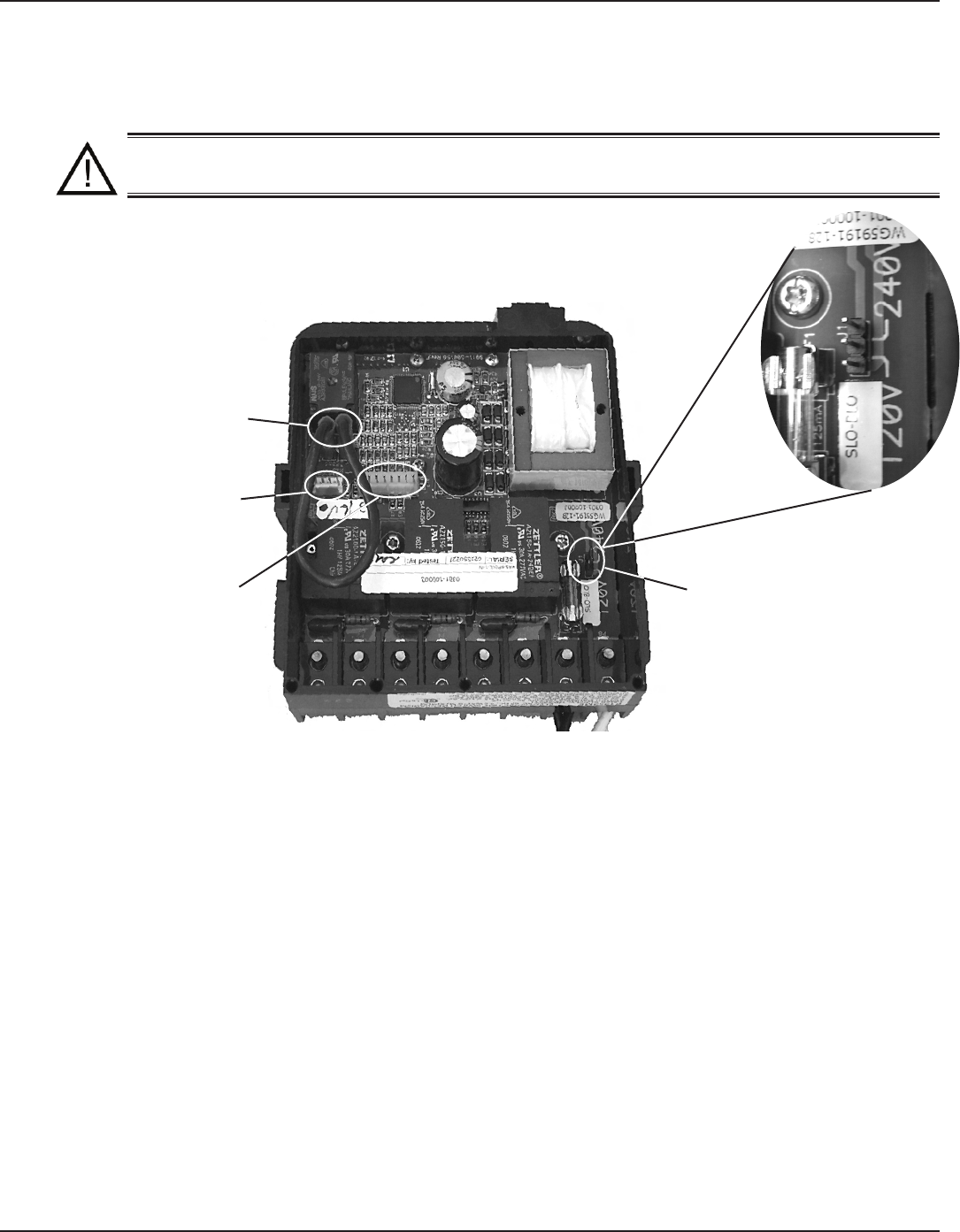
Identifying Connections and Selecting Proper Input Voltage
Figure 4-2 below shows the reverse side of the Three-Circuit Clock Control Panel. Detailed
connection information is provided below the diagram.
CAUTION: If the Source Voltage Selector Jumper is in the wrong position, the F1
fuse will blow and you may damage the circuit board, voiding the warranty.
Before making any connections: Set the Source Voltage Selector Jumper.
The factory default position for this jumper is the 240 Volt position.
If the input voltage for the clock is 120 Volts, change this jumper to the
120 Volt position.
Connection Detail
Freeze Probe Connection — For the Intermatic Freeze Sensor (178PA0001A), which is
necessary for the freeze protection circuit and programming to work. Disconnect power when
connecting the freeze sensor. Only an Intermatic sensor can be used. Refer to page 34 for
programming information.
Heater Firemen Switch Connection — For the remen switch wires that connect to the Pool/
Spa heater. If installing with a Wireless Remote Control, use the two brown wires coming
from the panel-mounted antenna to create the circuit between this switch and the heater.
Connectors should be ¼” female spade connectors crimped to insulated-type wire. This
connection is a simple SPST contact, and switches the supplied heater voltage. It does not
supply voltage to the heater thermostat. In non-wireless installations, clip the “loop” supplied,
then connect with wire nut connectors. Refer to page 33 for programming information.
Remote Control Connection — For the Intermatic Remote Control (133PE1484A), which
allows you to remotely turn On or Off all three available circuits. It also has status lights that
indicate when a load is On, Off or delayed. If using the Three-Button Wired Remote Control
(133PE1484A), it connects here as well.
1.
2.
•
•
•
Figure 4-2
Wired or Wireless
Remote Control
Connection
Freeze Probe
Connection
Heater Fireman Switch
Connection
Source Voltage
Selection Jumper