Intermatic 03140121 Home Pool/Spa Monitor User Manual Exhibit D Users Manual Part 1 per 2 1033 b3
Intermatic Inc Home Pool/Spa Monitor Exhibit D Users Manual Part 1 per 2 1033 b3
Contents
- 1. Exhibit D Users Manual Part 1 per 2 1033 b3
- 2. Exhibit D Users Manual Part 2 per 2 1033 b3
Exhibit D Users Manual Part 1 per 2 1033 b3
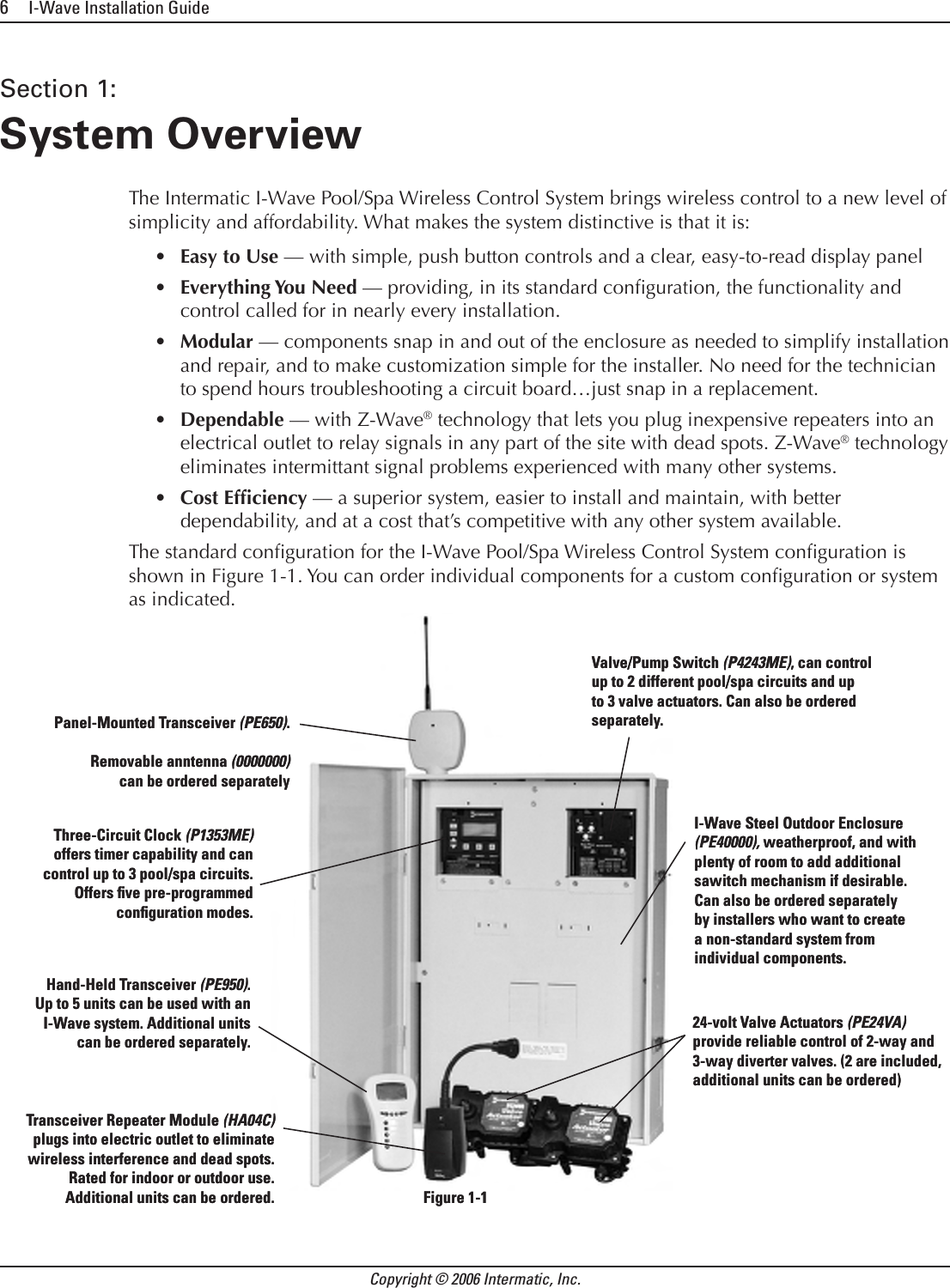


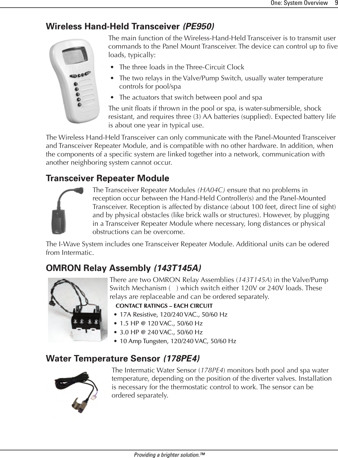
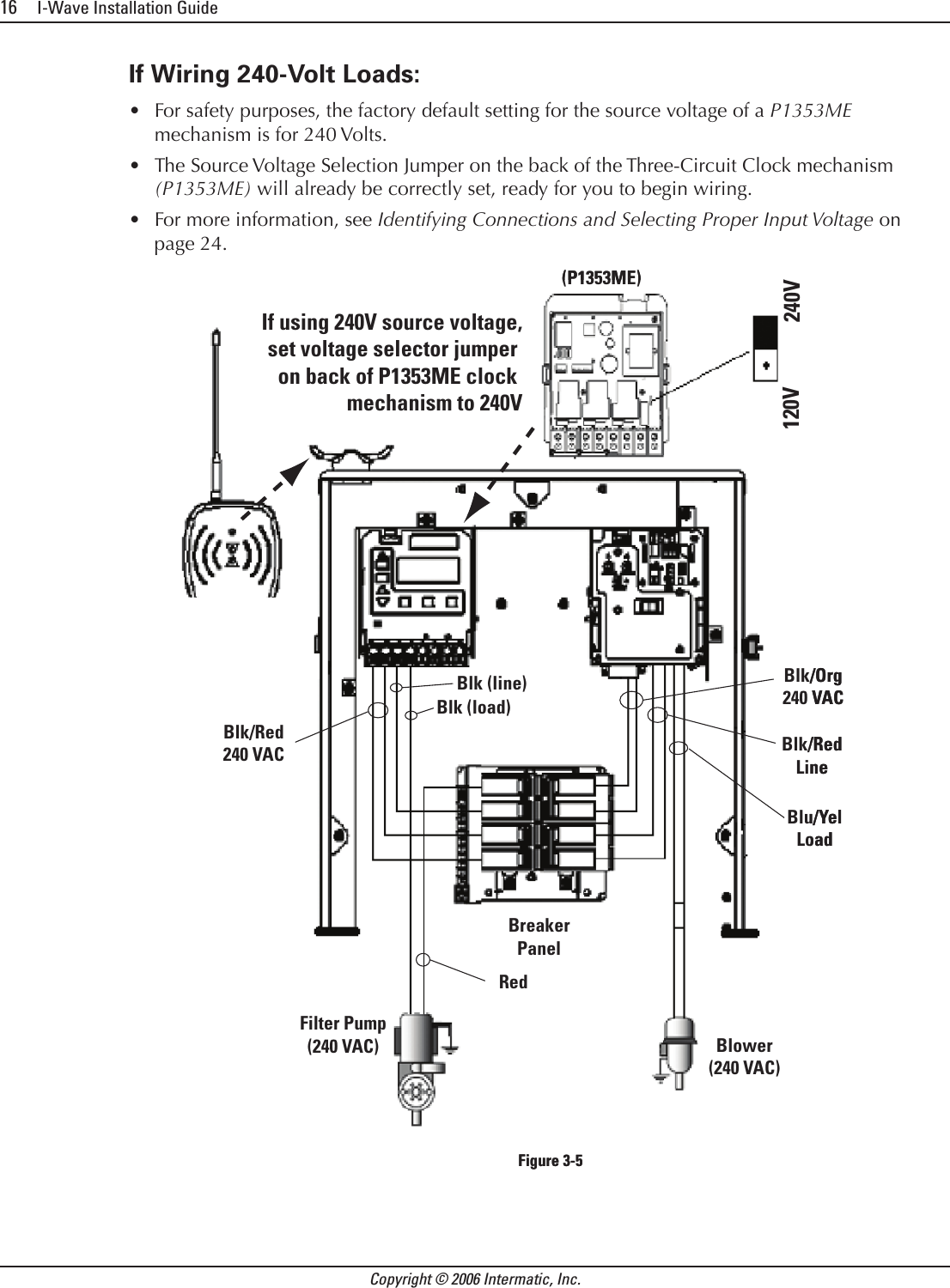
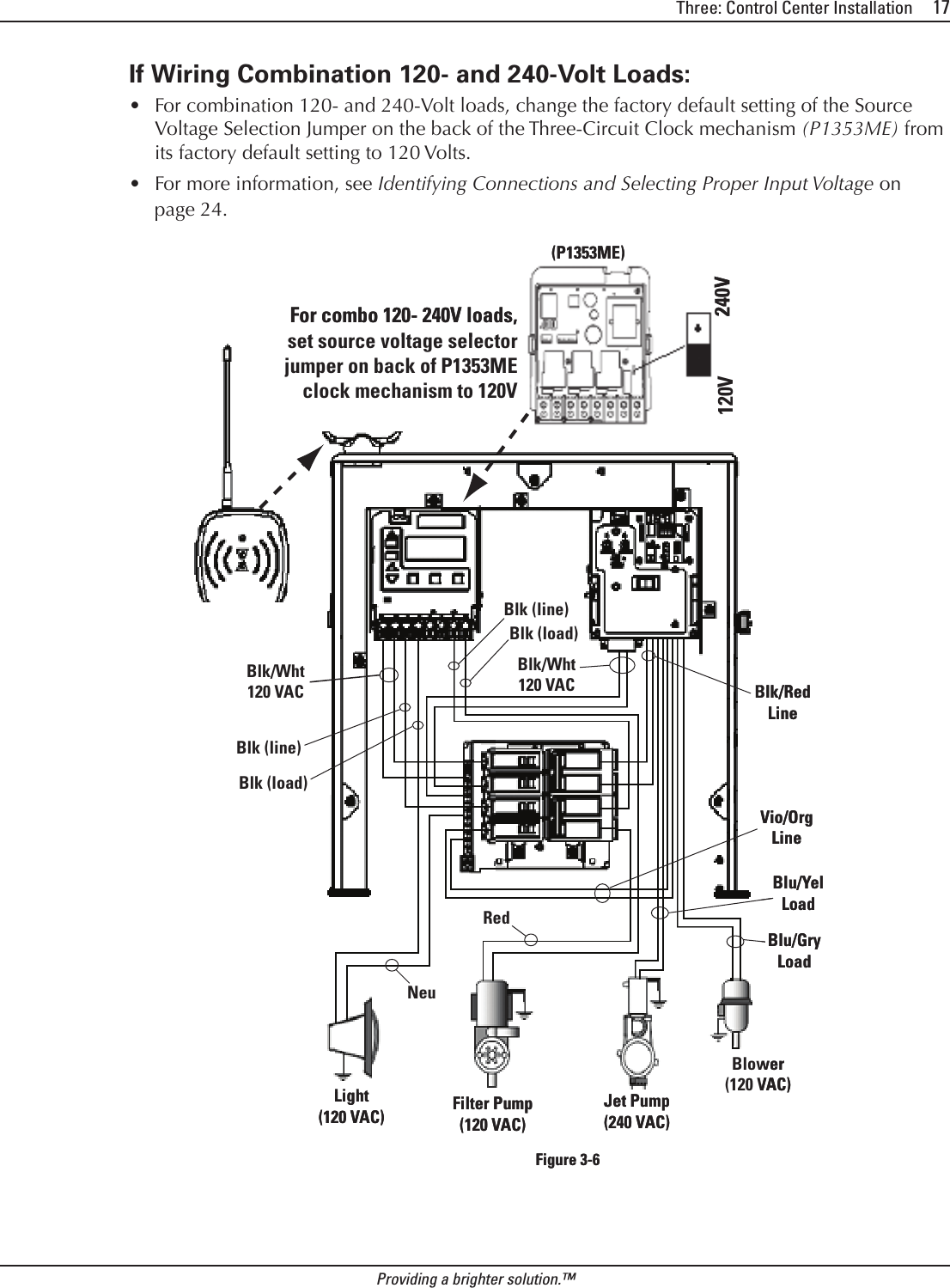
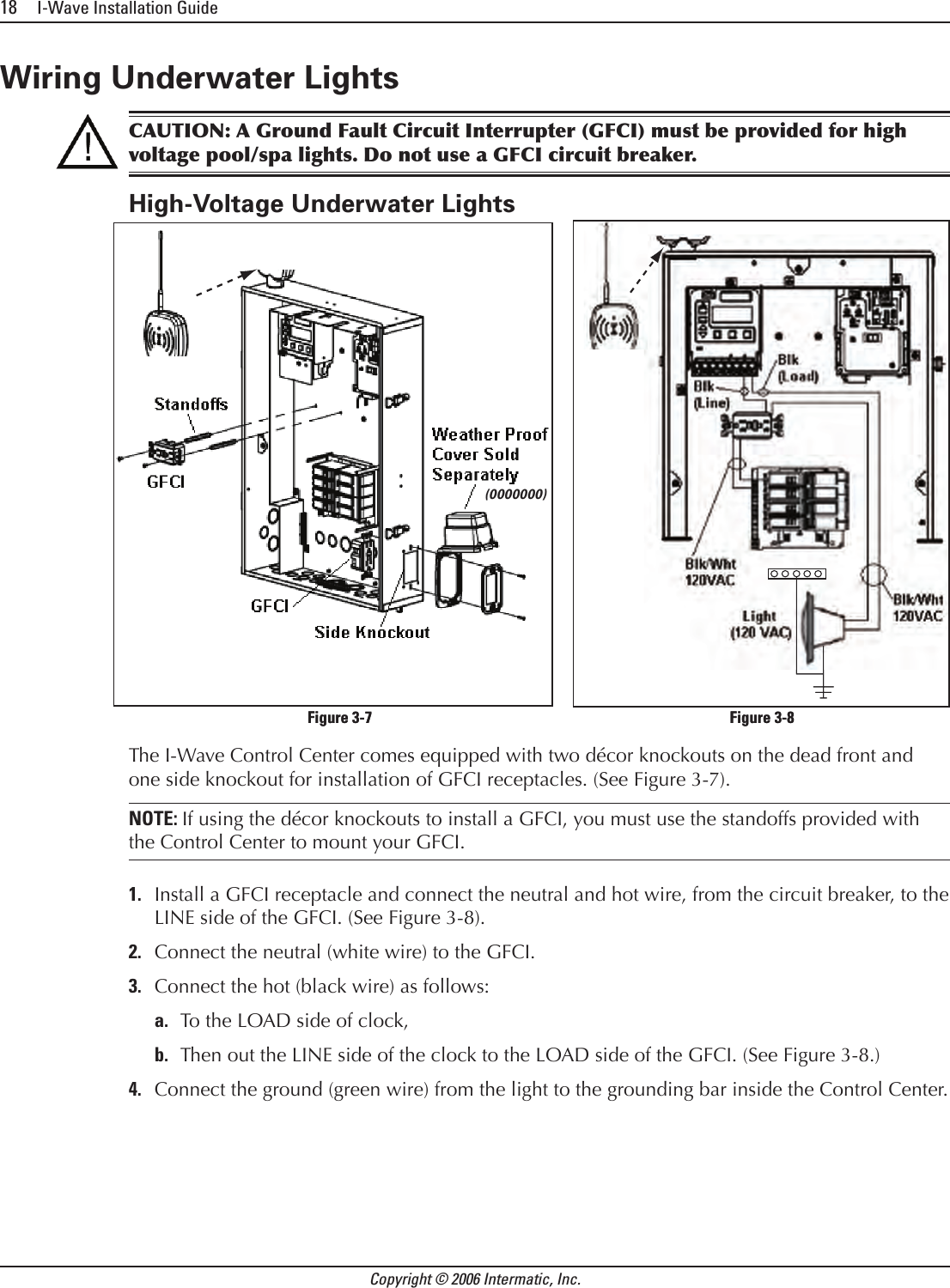
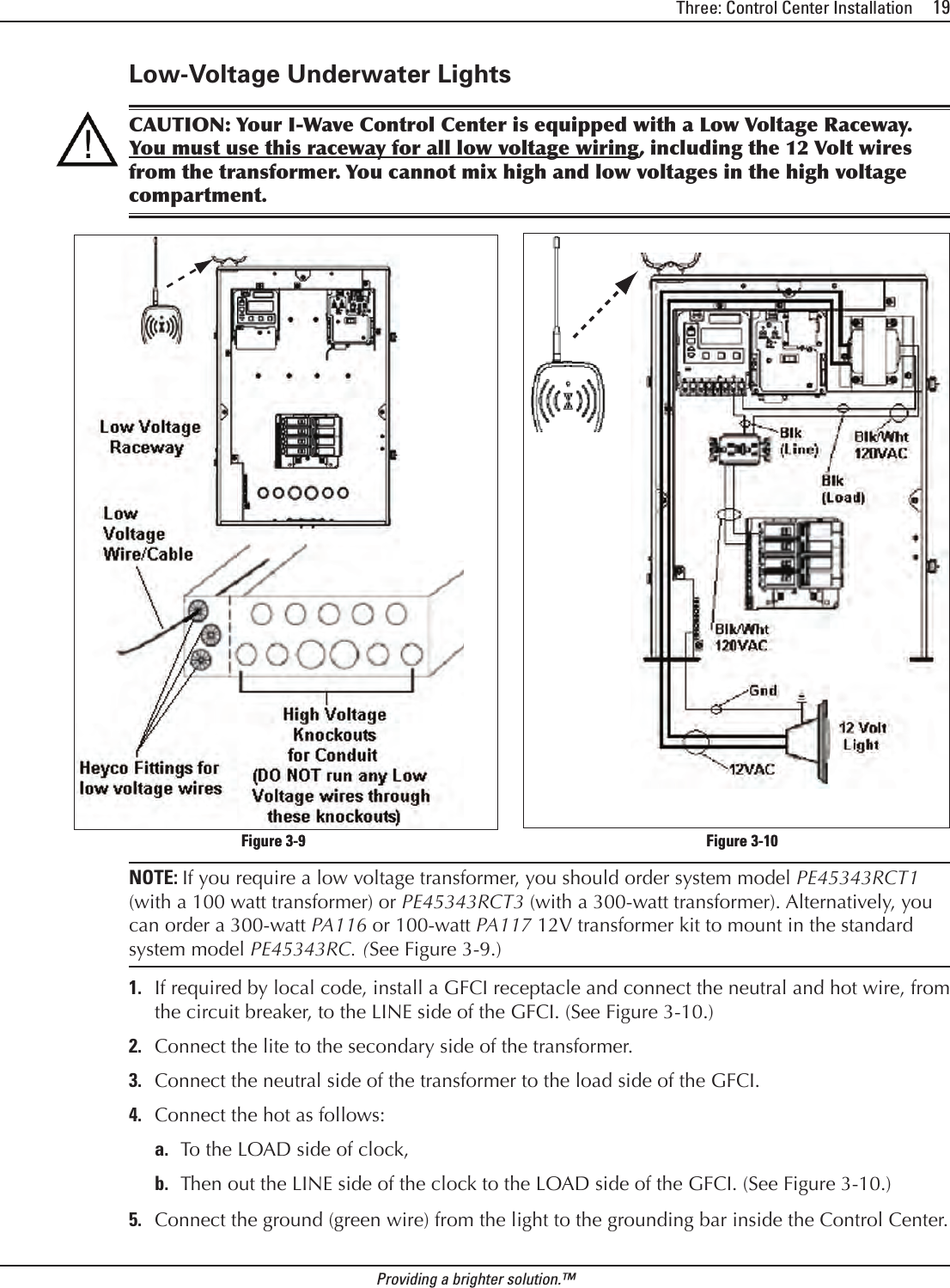
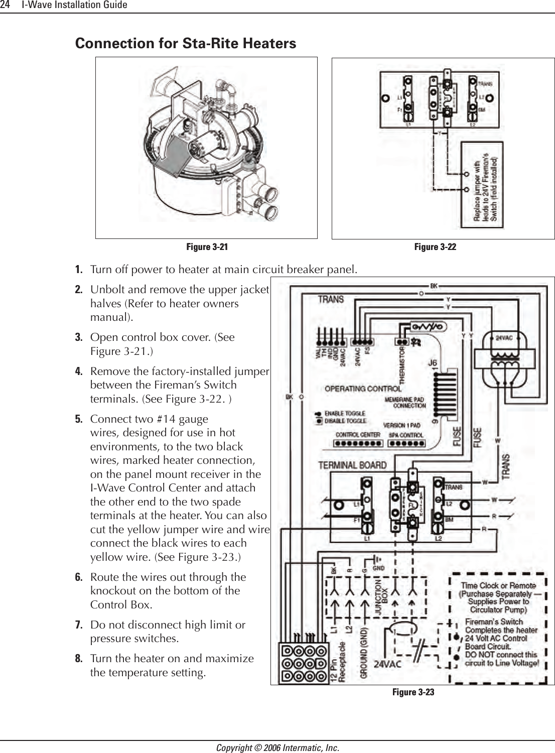
![Three: Control Center Installation 23Providing a brighter solution.™Connection for Hayward HeatersrsRemove heater service door on your Hayward Heater.Remove factory-installed wire connector between two (2) red wires labeled “CONNECTION FOR FIELD INSTALLED CONTROL SWITCH.” (See Figure 3-17.)Connect two #14 gauge wires, designed for use in hot environments, to the two red wires. (See Figure 3-18.) Wire the other end to the two black wires, marked heater connection, on the panel mount receiver in your I-Wave Control Center.Do not disconnect high limit or pressure switches.Turn the heater thermostat(s) to maximum setting.Turn the thermostat selector switch to the ON, HIGH, or SPA position.Connection for Pentair HeaterRemove heater service door on your Pentair Heater.Separate the black wires (common) from each other. (See Figure 3-19.)Connect two #14 gauge wires, designed for use in hot environments, to the two black wires, marked heater connection, on the panel mount receiver in the I-Wave Control Center and attach the other end to the two black wires on the heater. (See Figure 3-20.)Do not disconnect high limit or pressure switches.Turn the heater thermostat(s) to maximum setting.Turn the heater toggle switch on.1.2.3.4.5.6.7.1.2.3.4.5.6.Figure 3-17 — Wiring Before ModificationFigure 3-17 — Wiring Before ModificationFigure 3-18 — Wiring with [what??]Figure 3-18 — Wiring with [what??]Figure 3-19 — Wiring Before ModificationFigure 3-19 — Wiring Before ModificationFigure 3-20 — Wiring with AquaLink RSFigure 3-20 — Wiring with AquaLink RS](https://usermanual.wiki/Intermatic/03140121.Exhibit-D-Users-Manual-Part-1-per-2-1033-b3/User-Guide-638284-Page-23.png)