Intermatic 03140121 Home Pool/Spa Monitor User Manual Exhibit D Users Manual Part 2 per 2 1033 b3
Intermatic Inc Home Pool/Spa Monitor Exhibit D Users Manual Part 2 per 2 1033 b3
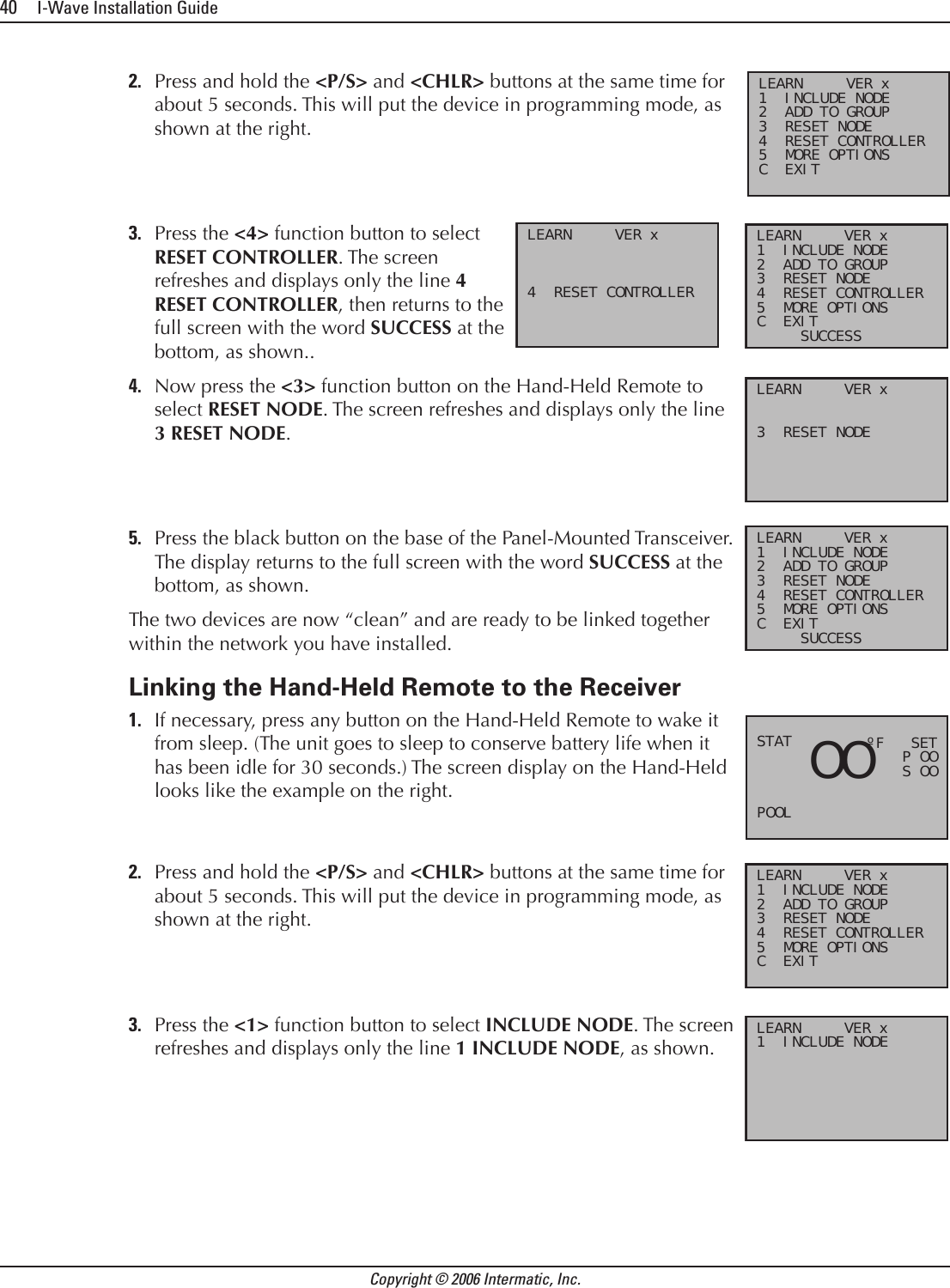
Contents
- 1. Exhibit D Users Manual Part 1 per 2 1033 b3
- 2. Exhibit D Users Manual Part 2 per 2 1033 b3
Exhibit D Users Manual Part 2 per 2 1033 b3
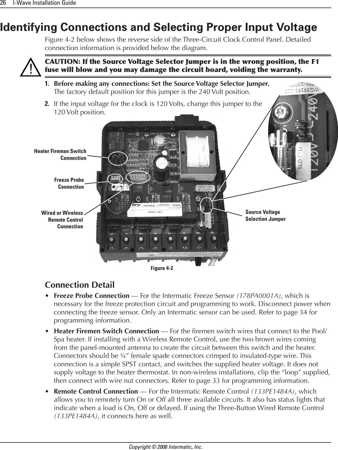
![Four: Programming the Three-Circult Clock Mechanism 31Providing a brighter solution.™Setting the On/Off Times for Each CircuitOverviewYou can set up to three separate ON/OFF times per load or circuit, and you can set specic times for them to turn on and off, i.e., you want the lter pump to run from noon till 4:00 P.M., or you want lights on from 7:00 P.M., off at 11:00 P.M., then on again at 6:00 A.M. and off at 8:00 A.M. ProcedurePROGRAMMING TIP: You can use the <ENTER> button to review all the events for each circuit. You can use the <PROGRAM> button to advance through each circuit and on to the next programming feature.If you pressed and released the program key from the previous procedure, the screen display should look like the illustration at the right. [If not, press and release the <PROGRAM> button twice.] Note that the display indicates that the rst event of circuit one has not been dened (NO EVENT1). Use the <Arrow> buttons to dene the Start time for the rst event (EVENT1) for circuit one. The screen displays: Once you are satised with the start time, press and release the <ENTER> button, saving the start time. The display will prompt for the Stop time for the rst event (EVENT1) for circuit one. The screen displays: Use the <Arrow> buttons to dene the Stop time for the rst event (EVENT1) for circuit one. Press and release the <ENTER> button when complete. The program will now advance to the second event (EVENT2) for circuit one, as shown below. Note that the display indicates that the second event of circuit one has not been dened (NO EVENT2). Repeat Steps 2 thru 4 to set a second event for circuit #1, and for subsequent events you wish to set up.1.2.3.4.5.NO EVENT 1 Not definedNO EVENT 1 Not definedFirst Event (EVENT1)Start TimeFirst Event (EVENT1)Start TimeStop TimeFirst Event (EVENT1) Stop TimeFirst Event (EVENT1)NO EVENT 2NO EVENT 2](https://usermanual.wiki/Intermatic/03140121.Exhibit-D-Users-Manual-Part-2-per-2-1033-b3/User-Guide-638285-Page-6.png)

![Intermatic, Inc. 7777 Winn Road Spring Grove, Illinois 60081-9698www.intermatic.com Intermatic Customer Service: 815-675-7000 (8 a.m. through 4:30 p.m. CT, Monday through Friday)©2006 Intermatic, Inc. Printed in U.S.A. [code number]](https://usermanual.wiki/Intermatic/03140121.Exhibit-D-Users-Manual-Part-2-per-2-1033-b3/User-Guide-638285-Page-27.png)