Intermatic 05200422 Home Pool/Spa Monitor User Manual Exhibit D Users Manual Part 2 per 2 1033 b3
Intermatic Inc Home Pool/Spa Monitor Exhibit D Users Manual Part 2 per 2 1033 b3
Contents
- 1. Exhibit D Users Manual Part 1 per 2 1033 b3
- 2. Exhibit D Users Manual Part 2 per 2 1033 b3
Exhibit D Users Manual Part 2 per 2 1033 b3
26 I-Wave Installation Guide
Copyright © 2006 Intermatic, Inc.
Identifying Connections and Selecting Proper Input Voltage
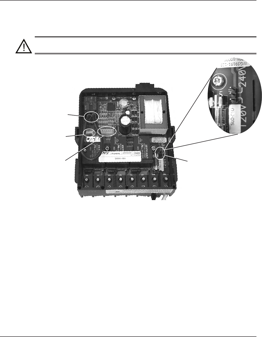
Figure 4-2 below shows the reverse side of the Three-Circuit Clock Control Panel. Detailed
connection information is provided below the diagram.
CAUTION: If the Source Voltage Selector Jumper is in the wrong position, the F1
fuse will blow and you may damage the circuit board, voiding the warranty.
Before making any connections: Set the Source Voltage Selector Jumper.
The factory default position for this jumper is the 240 Volt position.
If the input voltage for the clock is 120 Volts, change this jumper to the
120 Volt position.
Connection Detail
Freeze Probe Connection — For the Intermatic Freeze Sensor (178PA0001A), which is
necessary for the freeze protection circuit and programming to work. Disconnect power when
connecting the freeze sensor. Only an Intermatic sensor can be used. Refer to page 34 for
programming information.
Heater Firemen Switch Connection — For the remen switch wires that connect to the Pool/
Spa heater. If installing with a Wireless Remote Control, use the two brown wires coming
from the panel-mounted antenna to create the circuit between this switch and the heater.
Connectors should be ¼” female spade connectors crimped to insulated-type wire. This
connection is a simple SPST contact, and switches the supplied heater voltage. It does not
supply voltage to the heater thermostat. In non-wireless installations, clip the “loop” supplied,
then connect with wire nut connectors. Refer to page 33 for programming information.
Remote Control Connection — For the Intermatic Remote Control (133PE1484A), which
allows you to remotely turn On or Off all three available circuits. It also has status lights that
indicate when a load is On, Off or delayed. If using the Three-Button Wired Remote Control
(133PE1484A), it connects here as well.
1.
2.
•
•
•
Figure 4-2
Wired or Wireless
Remote Control
Connection
Freeze Probe
Connection
Heater Fireman Switch
Connection
Source Voltage
Selection Jumper
Four: Programming the Three-Circult Clock Mechanism 27
Providing a brighter solution.™
Circuit Ratings
CLOCK SOURCE VOLTAGE — 120/240VAC, 50/60 Hz.
POWER CONSUMPTION — 6.0 Watts Max.
CIRCUIT CONTACT CONFIGURATION — SPST
CIRCUIT SWITCH RATINGS ALL MODES:
20A Resistive, 120/240 VAC., 50/60 Hz
20A FLA@120 VAC, 96A LRA@120 VAC, 50/60 Hz
17A FLA@240 VAC, 80A LRA@240 VAC, 50/60 Hz
5 Amps Tungsten, 120/240 VAC, 50/60 Hz
5 Amps Ballast, 120/240 VAC, 50/60 Hz
EVENTS PER CIRCUIT — 3 On/Off Events Per Circuit
INTERNAL BATTERY POWER
40 Year retention for all programmed settings
Up to 24-hours
Mode Selection/Definition
IMPORTANT NOTE—There are ve modes to choose from, depending on your
pool or spa equipment pad conguration. Each mode has specic programming,
timing, and lockout features that are designed to work with specic types of pool
or spa equipment. Mode setting is generally done only once and usually during the
initial installation. It is purposely difcult to enter the mode-changing program
and should only be done by a Qualied Installer. Be sure you fully understand each
mode denitions and installation, prior to selecting the proper mode.
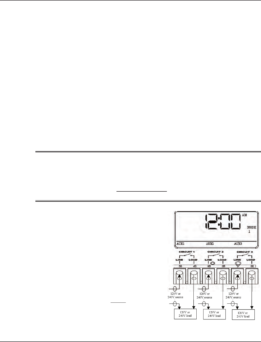
Mode 1 — (Aux1, Aux2, Aux3)
Each of the three single pole circuits are dened
generically, and can control any load within each
of its individual circuit ratings. All three circuits act
independent of each other.
•
•
•
•
•
•
•
Figure 4-3Figure 4-3
NOTE: This drawing illustrates
that only one leg is broken, with
the other leg going directly to
load, whether 120V or 240V.
NOTE: This drawing illustrates
that only one leg is broken, with
the other leg going directly to
load, whether 120V or 240V.
28 I-Wave Installation Guide
Copyright © 2006 Intermatic, Inc.
Mode 2 — (Pump High, Pump Low, Aux3)
Circuit one and two are dedicated single pole
outputs for a two-speed pump load. Circuits one and
two will never be ON at the same time, consistent
with a two-speed pump application. Circuit
three is single pole circuit for a generic load, and
independent of circuits one and two..
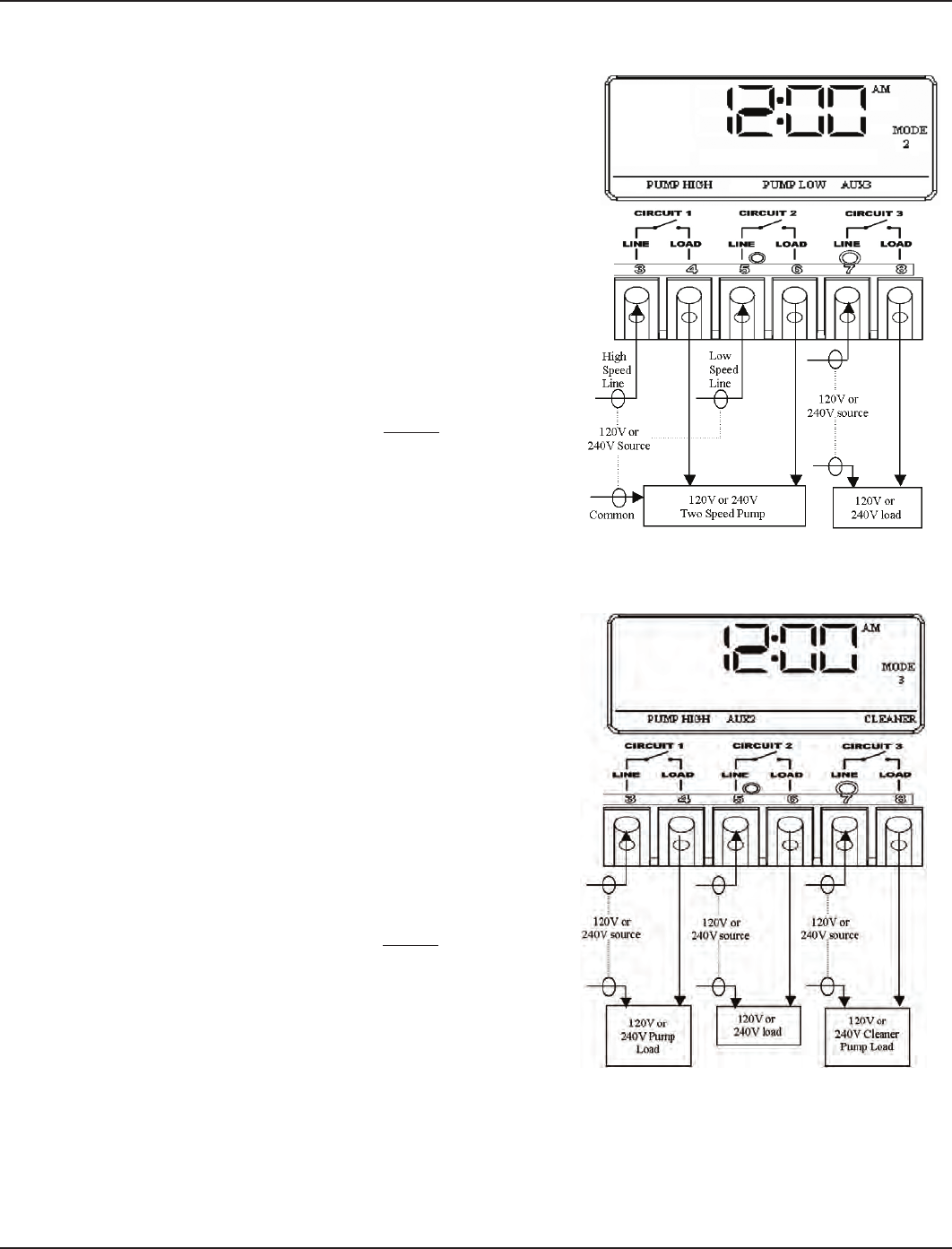
Mode 3 — (Pump, Aux2, Cleaner Pump)
Circuit one and three are dedicated single pole
outputs for a single speed pump working with a
pressure side cleaner pump. Circuit three will never
come on unless circuit one is on for at least one
minute, consistent with a pressure side cleaner
pump. Circuit two is a single pole circuit for a
generic load, independent of circuits one and three..
Figure 4-4Figure 4-4
NOTE: This drawing illustrates
that only one leg is broken, with
the other leg going directly to
load, whether 120V or 240V.
NOTE: This drawing illustrates
that only one leg is broken, with
the other leg going directly to
load, whether 120V or 240V.
Figure 4-5Figure 4-5
NOTE: This drawing illustrates
that only one leg is broken, with
the other leg going directly to
load, whether 120V or 240V.
NOTE: This drawing illustrates
that only one leg is broken, with
the other leg going directly to
load, whether 120V or 240V.
Four: Programming the Three-Circult Clock Mechanism 29
Providing a brighter solution.™
Mode 4 — (Pump High, Pump Low, Cleaner Pump)
Circuit one and two are dedicated single pole
outputs for a two-speed pump load. Circuits one and
two will never be ON at the same time, consistent
with a two-speed pump application. Circuit three
is also a dedicated single pole output for a pressure
side cleaner pump. Circuit three will never come
on unless circuit one is on for at least one minute,
consistent with a pressure side cleaner pump.
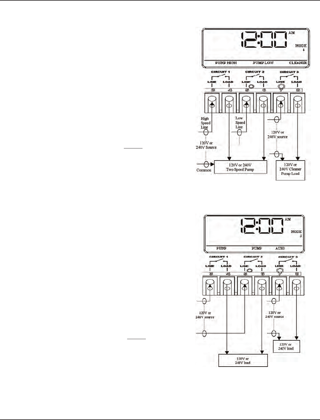
Mode 5 — (Pump, Pump, Aux3)
Circuit one and two are now coupled together
making up one circuit capable of switching the
power source to one pump. The On/Off button for
circuit one now controls both circuit one and two
simultaneously. The On/Off button for circuit two is
disabled. Circuit three remains a single pole circuit
for a generic load, and is independent of circuits one
and two..
Figure 4-6Figure 4-6
NOTE: This drawing illustrates
that only one leg is broken, with
the other leg going directly to
load, whether 120V or 240V.
NOTE: This drawing illustrates
that only one leg is broken, with
the other leg going directly to
load, whether 120V or 240V.
Figure 4-7Figure 4-7
NOTE: This drawing illustrates
that only one leg is broken, with
the other leg going directly to
load, whether 120V or 240V.
NOTE: This drawing illustrates
that only one leg is broken, with
the other leg going directly to
load, whether 120V or 240V.
30 I-Wave Installation Guide
Copyright © 2006 Intermatic, Inc.
Setting Mode
Overview
Determine the mode that would be best for your installation, then select it using the instructions
provided below.
Procedure
NOTE: If you don’t press a button within 60 seconds
while setting Mode, the control will save current
settings and return to normal operating mode.
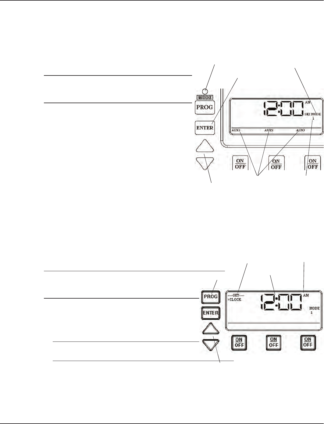
With a small pointed tool (i.e., pen, pencil,
screwdriver, etc.,), press and hold the <MODE>
button for about 5 seconds until the display
shows SET MODE and the Mode Number
blinks.
Use the <Arrow> buttons to cycle through all
ve available modes. Each circuit output will
be dened on the display as you cycle through
the available modes.
Once the desired mode number is displayed,
press and release the <ENTER> button. This
saves the mode number to memory and exits SET MODE programming.
Setting Time of Day
Overview
This procedure makes sure that timer-controlled actions will occur at the right time.
Procedure
NOTE: If you don’t press a button within 60 seconds
while setting Time of Day, the control will save
current settings and return to normal operating mode.
Press and release the <PROGRAM> button. The
displayed time will start to blink, and the program
menu will display Set Clock.
Use the <Arrow> buttons to change the time.
NOTE: Check the AM and PM indicator to make
sure your setting is correct.
When the time is set, you have two choices:
Press and release the <ENTER> button to save and exit programming.
Press and release the <PROGRAM> button to save and go on to the next programming
feature.
1.
2.
3.
1.
2.
3.
•
•
<Mode> button
<ENTER> button
“SET MODE”
<Arrow>
buttons
Circuit outputs will
be defined
Mode
Number
blinks
<Mode> button
<ENTER> button
“SET MODE”
<Arrow>
buttons
Circuit outputs will
be defined
Mode
Number
blinks
<PROGRAM>
button
Program Menu
Displayed Time
<Arrow>
buttons
AM/PM Indicator
<PROGRAM>
button
Program Menu
Displayed Time
<Arrow>
buttons
AM/PM Indicator
Four: Programming the Three-Circult Clock Mechanism 31
Providing a brighter solution.™
Setting the On/Off Times for Each Circuit
Overview
You can set up to three separate ON/OFF times per load or circuit, and you can set specic times
for them to turn on and off, i.e., you want the lter pump to run from noon till 4:00 P.M., or you
want lights on from 7:00 P.M., off at 11:00 P.M., then on again at 6:00 A.M. and off at 8:00 A.M.
Procedure
PROGRAMMING TIP: You can use the <ENTER> button to review all the events for each circuit.
You can use the <PROGRAM> button to advance through each circuit and on to the next
programming feature.
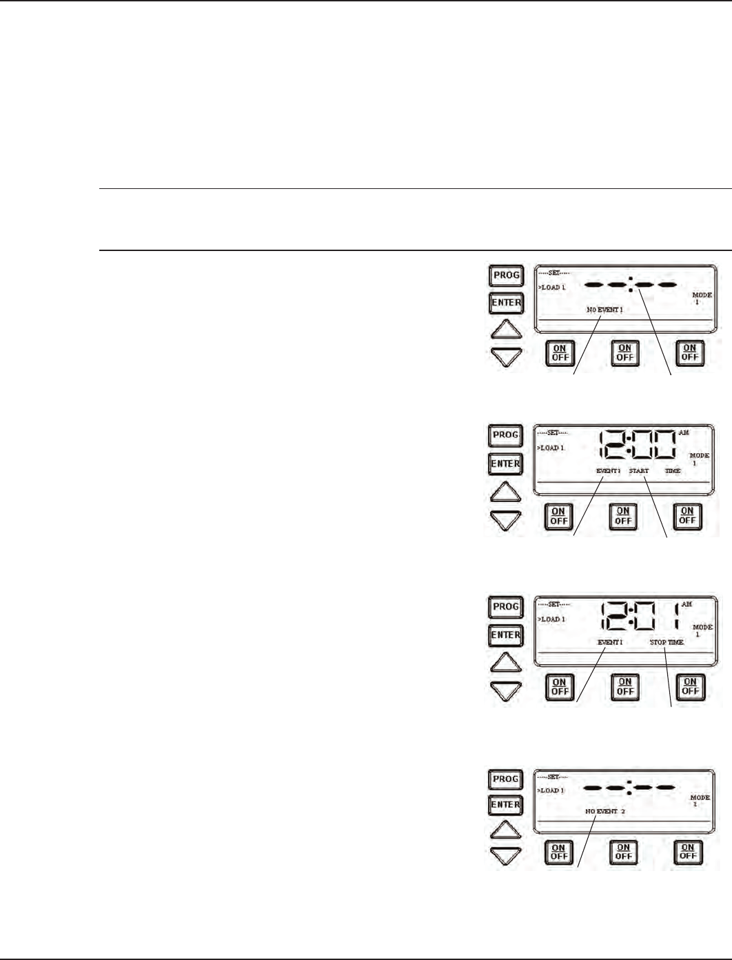
If you pressed and released the program key from the
previous procedure, the screen display should look
like the illustration at the right. [If not, press and
release the <PROGRAM> button twice.]
Note that the display indicates that the rst event of
circuit one has not been dened (NO EVENT1).
Use the <Arrow> buttons to dene the Start time for
the rst event (EVENT1) for circuit one. The screen
displays:
Once you are satised with the start time, press and
release the <ENTER> button, saving the start time. The
display will prompt for the Stop time for the rst event
(EVENT1) for circuit one. The screen displays:
Use the <Arrow> buttons to dene the Stop time
for the rst event (EVENT1) for circuit one. Press
and release the <ENTER> button when complete.
The program will now advance to the second event
(EVENT2) for circuit one, as shown below. Note that
the display indicates that the second event of circuit
one has not been dened (NO EVENT2).
Repeat Steps 2 thru 4 to set a second event for circuit
#1, and for subsequent events you wish to set up.
1.
2.
3.
4.
5.
NO EVENT 1 Not definedNO EVENT 1 Not defined
First Event
(EVENT1)
Start Time
First Event
(EVENT1)
Start Time
Stop Time
First Event
(EVENT1) Stop Time
First Event
(EVENT1)
NO EVENT 2NO EVENT 2

32 I-Wave Installation Guide
Copyright © 2006 Intermatic, Inc.
Notes on Setting On/Off Times for Each Mode
General Note
The ON/OFF buttons were provided for service operations, and for circumstances where
instantaneous response is required. If the intent is to turn equipment on and off everyday at
the same time, programming individual events will make sure these functions take place.
All circuits will respond to a programmed off time. Therefore, when a circuit is turned on with
the ON/OFF button, it automatically turns itself off at the end of the next programmed event.
If there are no events programmed, the circuit stays on until the ON/OFF button is pressed
again.
If the ON/OFF button is pressed while the corresponding circuit is on, it turns the circuit
off and supersedes any program in progress. The priority is always given to the last manual
operation.
Mode 1 — (Aux1, Aux2, Aux3)
All three of the available circuits act independently, and up to three individual on/off times can
be set for each circuit independently.
Mode 2 — (Pump High, Pump Low, Aux 3)
In this mode circuits 1 & 2 are connect to a two speed pump, and Aux 3 is connected
independent of circuits 1 & 2. In the event that you program high and low speed to be on at the
same time or if their independent ON times overlap, high speed will always take precedence.
Example: Low speed is programmed to come ON at noon and run until 6 PM. High speed is
programmed to come on at 2 PM and turn off at 4 PM. In this case the pump will come ON
at noon in low speed, go to high speed at 2 PM, and back to low speed at 4 PM, and shut off
at 6 PM.
All manual ON operations for circuits 1 & 2 override all programmed ON times. Therefore, any
desired low and high-speed run combinations need to be programmed as separate events and
cannot controlled by combining the manual ON/OFF button with a scheduled event. The last
speed started manually has priority over all prior automatic and manual operations.
Example: You would like to run the pump in high speed for 6 hours and low speed for the
remainder of the time. Program a 6-hour event for high speed, and an 18-hour event for low
speed. Do not turn the low speed on manually, and program a 6-hour event for high speed.
The high speed will not occur.
Mode 3 — (Filter Pump, Aux2, Cleaner Pump)
The cleaner pump cannot turn on unless the lter pump has been on for at least 30 seconds.
Therefore, for any ON/OFF time programmed for the cleaner pump, the lter pump will come on
rst, followed 30 seconds later by the cleaner pump. Both the cleaner and lter pump will turn
off according to the programmed off time. When programming an event for the cleaner pump, it
is not necessary to program a separate event for the lter pump, as it will automatically turn on
when the cleaner pump turns on at its next scheduled on time.
•
•
•
•
Four: Programming the Three-Circult Clock Mechanism 33
Providing a brighter solution.™
Mode 4 – (Pump High, Pump Low, Cleaner Pump)
Mode 4 is a combination of Modes 2 and 3, so refer above to Modes 2 and 3 for programming
specics. Note that if the cleaner pump is programmed to come ON, the control will turn ON
the lter pump to high speed 30 seconds prior to turning the cleaner pump ON, even if the lter
pump is currently on in low speed.
Mode 5 – (Aux1, Aux3)
Both of the available circuits act independently, similar to Mode 1. Therefore you can set up to
three individual ON/OFF times for each circuit and they will act independently.
Setting the Heater’s Cool Down Time (optional)
Overview
The heater’s cool down time is a time dened by the programmer. This time is dened as the
additional time the pump will run, over and beyond the desired pump OFF time, to make sure
the heater is cooled down before shutting off.
If the heater were to stay on after the pump had shut off, the water in the pipe
could boil, damaging the system. Refer to heater manufacturer for specic time.
If a cool down time is programmed, the cool down cycle will occur in all cases, even if the user
turns off the pump. To override the cool down time, press and release the ON/OFF key a second
time during the cool down cycle. The cool down feature only applies to Circuit #1, in all modes.
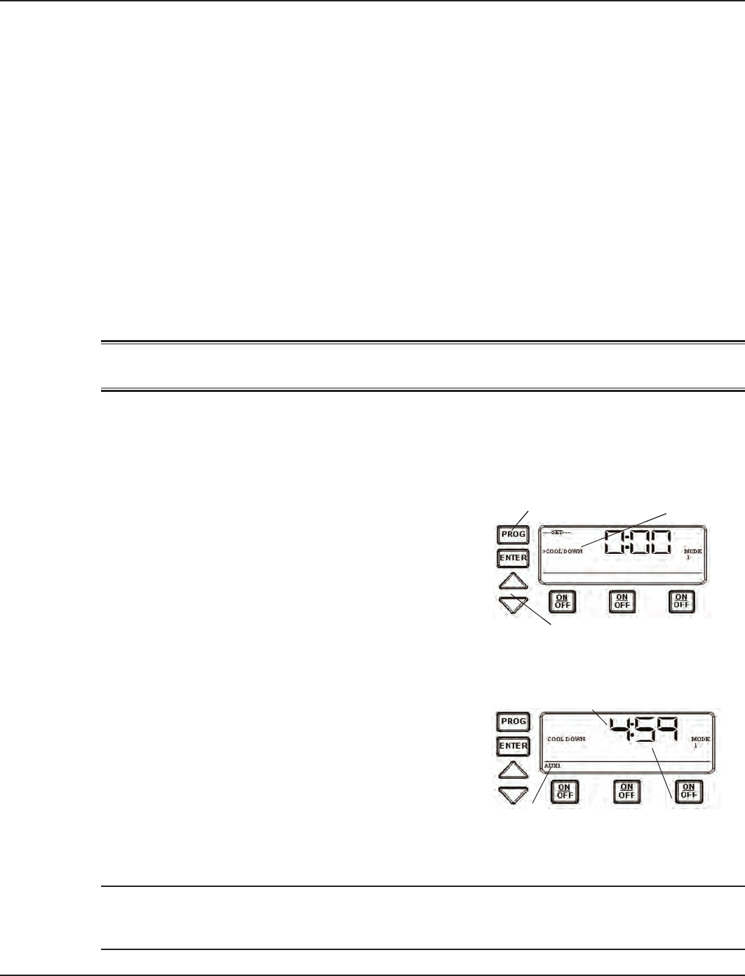
Procedure
Use the <PROGRAM> button to advance to the COOL
DOWN setting, as shown. The default cool down time
is zero.
Use the <ARROW> buttons to modify the cool down
time. The programming range is from zero to fteen
minutes and no seconds.
When you’ve set the cool down time, press the
<ENTER> button to save and exit, or the <PROGRAM>
button to save and advance to the next programming feature.
The display will look like the example shown at the right
when the Heater’s Cool Down Time feature is activated. In
this example, the cool down time was set for 5 minutes,
and is in the process of counting down to zero, showing
minutes and seconds.
The AUX1 indicator is blinking, indicating that the Cool
Down feature is activated for Circuit #1. The Cool Down
feature only affects Circuit #1. When the countdown
display reaches zero, Circuit #1 will open and the time
display will change back to the time of day.
NOTE: You can override the Cool Down feature during countdown by pressing and releasing the
ON/OFF button associated with Circuit #1. This will end the cool down cycle and immediately
power off Circuit #1.
1.
2.
3.
COOL DOWN
<PROGRAM> button
<ARROW> buttons
COOL DOWN
<PROGRAM> button
<ARROW> buttons
Counting Down
Minutes and Seconds
AUX1 Indicator
Blinking
Counting Down
Minutes and Seconds
AUX1 Indicator
Blinking
34 I-Wave Installation Guide
Copyright © 2006 Intermatic, Inc.
Setting Freeze Temperature (optional)
Overview
Freeze temperature programming will not appear unless the optional Intermatic Freeze Sensor
(178PA28A) has been installed. This is the only freeze sensor that will work with the P1353ME
Controller.
Power must be disconnected when connecting the 178PA28A sensor.
If Intermatic Freeze Sensor (178PA28A) has been installed, use the following procedure to
program freeze temperature.
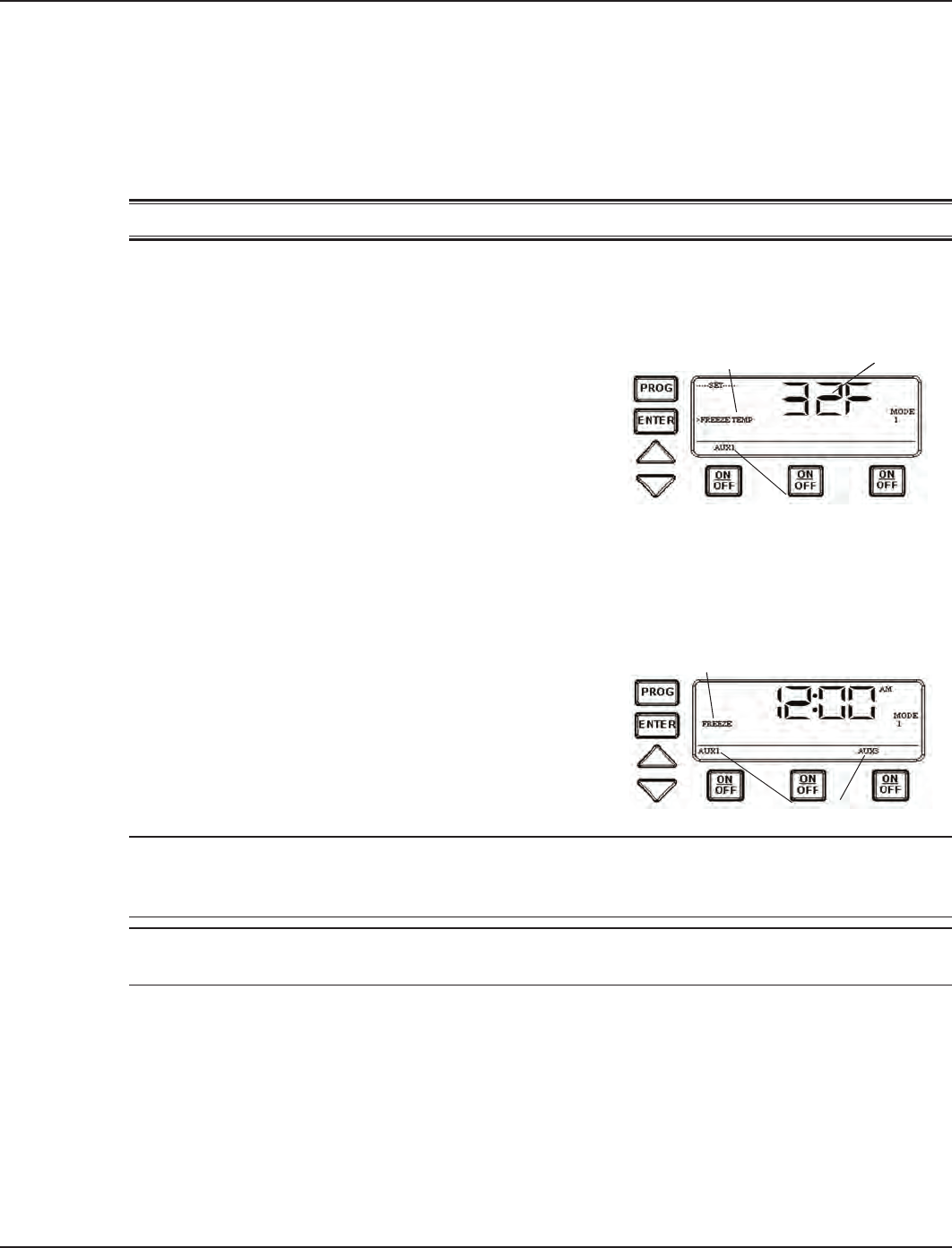
Procedure
Use the <PROGRAM> button to advance to the
Freeze Temp setting, as shown. The 1st Circuit and
32°F are the factory default settings.
Use the <ARROW> buttons to modify the desired
freeze temperature trip point. The programming range
is 32° through 44° F.
After you have set the desired trip temperature, push
and release the desired ON/OFF button to indicate
which circuits should come ON when the trip temperature is reached.
When programming is complete, , press the <ENTER> button to save and exit, or the
<PROGRAM> button to save and advance to the next programming feature.
The display will look like the example shown at the
right when the Freeze Control feature is activated. In
this example, the freeze sensor was connected, enabling
the Freeze Control feature. Circuits #1 and #3 were
programmed to come on during a Freeze condition.
AUX1 and AUX3 will blink, indicating that the control
has activated these two circuits due to a freeze condition.
NOTE: You can override the circuits during a freeze condition by pressing and releasing the
corresponding ON/OFF buttons. This will turn the devices OFF. The override will only last one
hour, so if the freeze condition still exists after one hour, Circuits #1 and #3 will come back on.
NOTE: Freeze protection stays enabled until the outside air temperature exceeds the
programmed freeze temperature for more than one minute.
1.
2.
3.
4.
32°F
Freeze Temp
1st Circuit
32°F
Freeze Temp
1st Circuit
Aux #1 and #3
Freeze
Aux #1 and #3
Freeze
Five: Programming the Valve/Pump Switch Mechanism 35
Providing a brighter solution.™
Section 5:
Programming the Valve/Pump Switch
Mechanism
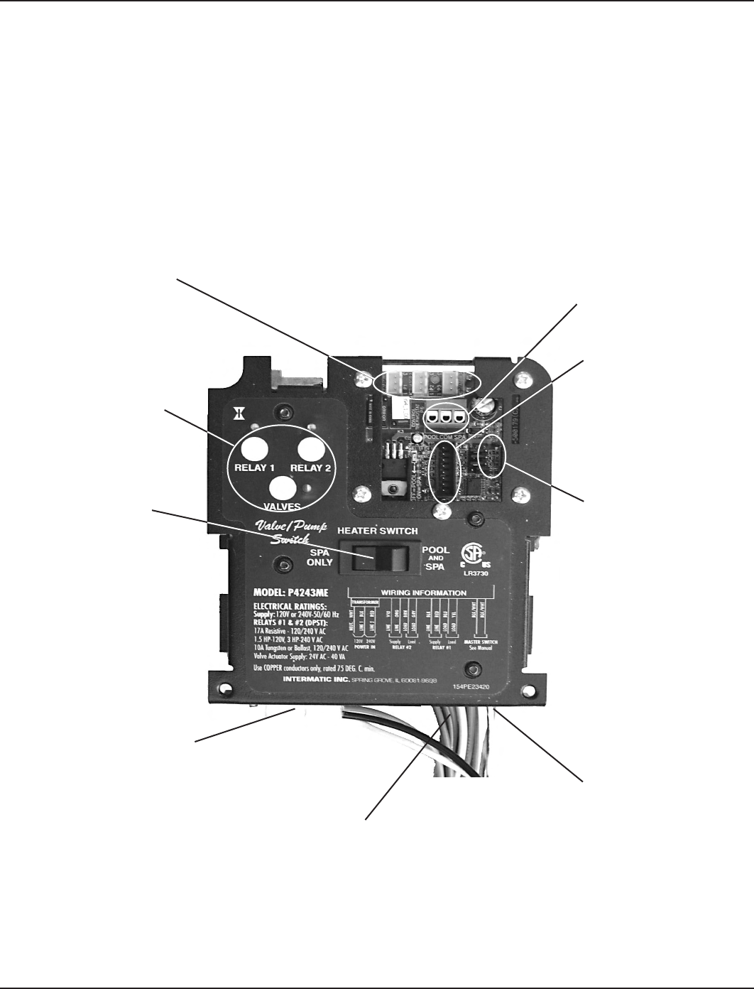
Overview of the Valve/Pump Switch Control Panel
Front View
ACTUATOR CONNECTION —
The Pump/Valve Switch
mechanism supports up to
three 24V valve actuators.
HEATER THERMOSTAT CONNECTOR — supports the three
wires from the heaters thermostat. The wires should be
marked Pool, Common, and Spa. The mechanism will
switch the thermostat when the actuators change.
WIRED OR WIRELESS
CONNECTOR will support
either the wired spa side
remote or the panel-mounted
wireless transceiver.
JUMPER BLOCK
CONFIGURATION — used
when a simple single-pole
single through switch
is going to be used in
conjunction with the Sensor
Line to control the Pool to
Spa Mech. This is the most
inexpensive way to achieve
total pool/spa automation.
SENSOR LINE — allows the
mechanism to be controlled by
a single pole sing throw switch
(i.e. toggle switch, relay, wall
switch, etc.). See page xxx for
details.
SERVICE BUTTONS —
allow you to operate the
mechanism at the panel.
POOL/SPA
THERMOSTAT SWITCH
— allows you to switch
between the pool and
spa thermostat or just
the spa only. In the spa
only mode, the pool
thermostat is disabled.
DUAL-VOLTAGE TRANSFORMER
— is capable of being powered
with either 120V or 240V.
CIRCUITS 1 & 2 — The pool to spa mechanism
supports up to two auxiliary 3HP circuit loads. You
can have different source voltages for each circuit,
depending on your equipment requirements.
36 I-Wave Installation Guide
Copyright © 2006 Intermatic, Inc.
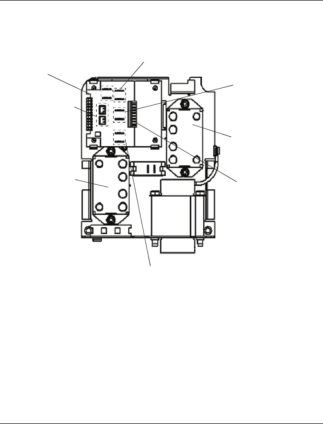
Rear View
24VAC POWER-IN FOR PC
BOARD — The circuit board
for the Pump/Valve Switch
requires 24VAC power
from the transformer.
OMRON CONNECTIONS
— Each of the two Omron
relays connects to the PC
board at these points.
SENSOR LINE PLUG IN — The pool to spa mechanism
supports up to two auxiliary 3HP circuit loads. You
can have different source voltages for each circuit,
depending on your equipment requirements. The sensor line
allows the mechanism to be controlled by a single-pole
single throw switch. (i.e., a toggle switch, relay, wall switch, etc.)
POOL/SPA SWITCH CONNECTION — located on the face of the Pump/
Valve Switch mechanism connects to the PC board at this point, and
allows you to switch between the pool and spa thermostat or just the
spa only. In the spa only mode, the pool thermostat is disabled.
EXTERNAL TIMER PLUG IN —
into the PC board at this point
to control relay #1. Please see
page xx for instructions on
using an external timer.
OMRON RELAY #2 — This
relay can switch either
120V or 240V loads.
Can be ordered separately
(145T145A)
CONTROL FACE PLUG IN — a
control pad for service. The
control pad connects to the
PC board at this point.
OMRON RELAY #1 — This
relay can switch either
120V or 240V loads. Can
be ordered separately (145T145A)
Five: Programming the Valve/Pump Switch Mechanism 37
Providing a brighter solution.™
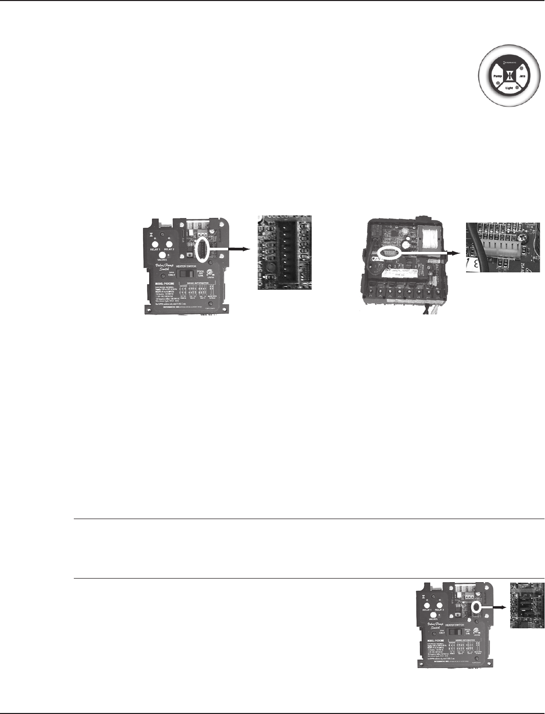
Installing the Three-Button Wired Remote Control
The Three-Button Wired Remote Control (133PE1484A) can be installed to
plug into either the Three-Circuit Clock (PE1353ME) or Valve/Pump Switch
(PE4243ME).
When plugged into one of these mechanisms, it replaces the wireless method
of controlling the three circuits within the mechanism. For example, if you plug
the Three-Button Wired Remote Control into the Valve/Pump Switch, the two
relays and the pool/spa control will no longer be controllable using the Hand-
Held Wireless Remote. The Three-Button Wired Remote Control must be installed where a third
mechanism is needed in the enclosure box, since the Wireless Hand-Held Remote. can only
control two mechanisms.
See illustrations below for connection detail.
Installing Other Wired Remote Connections (Master Switch)
You can install any ON/OFF switch to the sensor line to provide wired control of the two relays
and the Pool/Spa actuators in the Valve/Pump Switch (PE4243ME), giving you dual control
(master switch and wireless) control of these circuits.
In use, a wired remote switch toggles all circuits to their opposite state. This means that if
Relays 1 and 2 are ON, and the actuator valve is in SPA, the wired remote switch will turn
Relays 1 and 2 OFF, while switching the actuator valve to POOL. It does this by toggling
Relays 1 and 2 and the actuator valve back and forth from their default state in order to return
the system to its default setting after the owner has made temporary changes to the settings.
For example, if using the phone while sitting in the spa, the owner may turn off the jets to
reduce noise. The next time the Master Switch is used, the jets will revert to being ON when
the system is in spa mode.
INSTALLATION ISSUE: If you want to change the default state for your installation and you
manually press the switches on the Valve/Pump Switch control panel, your changes will be
temporary with the wired remote switch (master switch) because it will return the circuits to their
factory default setting when it is activated, eliminating your custom settings.
Therefore, if you want to make permanent changes to the factory
defaults, you must use the jumper, as shown at the right. Then the
wired remote switch’s return to defaults will not delete your changes.
Putting the jumper on pins 1 and 2 sets the system default state
to OPEN = OFF. This is the factory default state.
Putting the jumper on pins 2 and 3 sets the system default state
to CLOSED = ON.
•
•
Three-Button Wired
Remoe Control
(133PE1484A)
Three-Button Wired
Remoe Control
(133PE1484A)
Connection to
Valve/Pump Switch
(PE4243ME)
Connection to
Valve/Pump Switch
(PE4243ME)
Connection to
Three-Circuit Clock
(PE1353ME)
Connection to
Three-Circuit Clock
(PE1353ME)
38 I-Wave Installation Guide
Copyright © 2006 Intermatic, Inc.
Connecting the Heater Switch to Control Temperatures
Overview
The primary means of controlling the heater is using the Hand-Held Controller. If there is no
Hand-Held Controller in the system, the heater switch provides an alternate method.
This Switch can be also used in conjunction with the Hand-Held Controller to provide maximum
temperature limits for the pool and spa. Control by this Switch is primary over the Hand-Held.
Procedure
Wire the heater thermostats to the blue connectors visible
on the front of the Valve/Pump Switch, as shown.
Set limits on the heaters themselves, so that when
the Switch powers the heaters, they will reach the
temperatures you have set.
Make temperature adjustments at the heaters themselves.
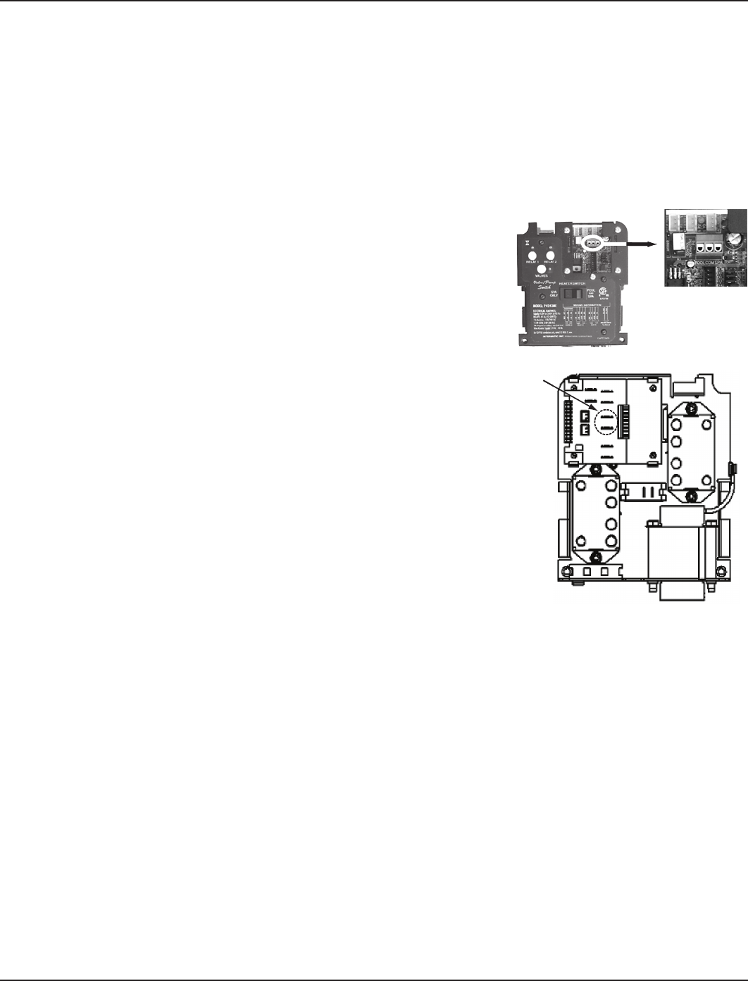
If Connecting an External Timer:
Overview
You can add an external timer to a circuit, converting it from
“on-demand” control to timer control. External timers are
available from Intermatic but are not included with the I-
Wave system. When connected to the system, the external
timer powers Relay 1 on and off according to its time
settings.
Procedure
Connect your timer to Relay 1 on the back of the Valve/
Pump Switch Mechanism, as shown in the circled area of
the illustration at the right.
1.
2.
3.
Six: Programming the Hand-Held Transmitter 39
Providing a brighter solution.™
Section 6:
Programming the Hand-Held Remote
Transceiver
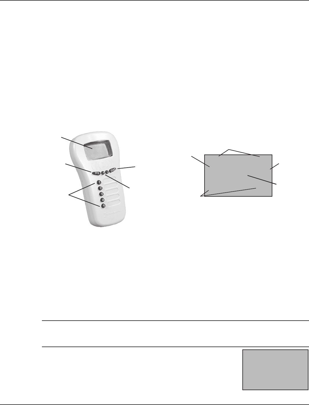
Overview
The Hand-Held Remote Tranceiver (PE950) is the focal point of user convenience. It’s water-
resistant, shock-resistant, and is easy to program for handy remote control of the functions at a
specic pool-spa installation. An assortment of self-stick labels are provided to identify the
functions you program into the ve control buttons. We suggest that you program the device rst,
then apply the appropriate label from the assortment supplied.
Synchronizing the Hand-Held with the Receiver
When you’ve nished physical installation and wiring and have enabled power to the control
center, you need to synchronize the Hand-Held with the Panel-Mounted Transceiver. This is a
two step process: rst, delete any programming that might exist in the Hand-Held Remote and
Receiver, then synchronize the two devices with each other.
Deleting Any Existing Programming
This procedure deletes any existing programming from the Remote and Receiver units so they are
ready to be programmed into the network of this installation.
NOTE: If the word FAILURE instead of SUCCESS appears at the bottom of the screen during any of
the following steps, repeat the programming procedure, then try replacing the batteries in the
Hand-Held. If the problem persists, contact Intermatic Customer Service.
Press any button on the Hand-Held Remote to wake it from sleep.
(The unit goes to sleep to conserve battery life when it has been idle
for 30 seconds.) The screen display on the Hand-Held looks like the
example on the right.
1.
Actuator
Button
(Pool/Spa)
(not currently
functional)
Display Screen
ON/OFF
Function
Buttons
Up/Down
Arrow Buttons
Actuator
Button
(Pool/Spa)
(not currently
functional)
Display Screen
ON/OFF
Function
Buttons
Up/Down
Arrow Buttons
1 2 3 4 5
STAT
OK
POOL SPA
73ºF SET
P 73
S 85
When you see
these numbers, it means
that circuit is ON
“POOL” or “SPA”
tells which mode
the system is in
“OK” means
Hand-Held
is communicating
with panel-mounted
transceiver
Current Temp
of the Pool or Spa,
depending on
whichever mode
the system is in
Temp settings
for pool (P)
or spa (S)
Detail on Hand-Held Remote Display ScreenDetail on Hand-Held Remote Display Screen
STAT
POOL
OO
ºF SET
P OO
S OO
STAT
POOL
OO
ºF SET
P OO
S OO

40 I-Wave Installation Guide
Copyright © 2006 Intermatic, Inc.
Press and hold the <P/S> and <CHLR> buttons at the same time for
about 5 seconds. This will put the device in programming mode, as
shown at the right.
Press the <4> function button to select
RESET CONTROLLER. The screen
refreshes and displays only the line 4
RESET CONTROLLER, then returns to the
full screen with the word SUCCESS at the
bottom, as shown..
Now press the <3> function button on the Hand-Held Remote to
select RESET NODE. The screen refreshes and displays only the line
3 RESET NODE.
Press the black button on the base of the Panel-Mounted Transceiver.
The display returns to the full screen with the word SUCCESS at the
bottom, as shown.
The two devices are now “clean” and are ready to be linked together
within the network you have installed.
Linking the Hand-Held Remote to the Receiver
If necessary, press any button on the Hand-Held Remote to wake it
from sleep. (The unit goes to sleep to conserve battery life when it
has been idle for 30 seconds.) The screen display on the Hand-Held
looks like the example on the right.
Press and hold the <P/S> and <CHLR> buttons at the same time for
about 5 seconds. This will put the device in programming mode, as
shown at the right.
Press the <1> function button to select INCLUDE NODE. The screen
refreshes and displays only the line 1 INCLUDE NODE, as shown.
2.
3.
4.
5.
1.
2.
3.
LEARN VER x
1 INCLUDE NODE
2 ADD TO GROUP
3 RESET NODE
4 RESET CONTROLLER
5 MORE OPTIONS
C EXIT
LEARN VER x
1 INCLUDE NODE
2 ADD TO GROUP
3 RESET NODE
4 RESET CONTROLLER
5 MORE OPTIONS
C EXIT
LEARN VER x
4 RESET CONTROLLER
LEARN VER x
4 RESET CONTROLLER
LEARN VER x
1 INCLUDE NODE
2 ADD TO GROUP
3 RESET NODE
4 RESET CONTROLLER
5 MORE OPTIONS
C EXIT
SUCCESS
LEARN VER x
1 INCLUDE NODE
2 ADD TO GROUP
3 RESET NODE
4 RESET CONTROLLER
5 MORE OPTIONS
C EXIT
SUCCESS
LEARN VER x
1 INCLUDE NODE
2 ADD TO GROUP
3 RESET NODE
4 RESET CONTROLLER
5 MORE OPTIONS
C EXIT
SUCCESS
LEARN VER x
1 INCLUDE NODE
2 ADD TO GROUP
3 RESET NODE
4 RESET CONTROLLER
5 MORE OPTIONS
C EXIT
SUCCESS
LEARN VER x
3 RESET NODE
LEARN VER x
3 RESET NODE
STAT
POOL
OO
ºF SET
P OO
S OO
STAT
POOL
OO
ºF SET
P OO
S OO
LEARN VER x
1 INCLUDE NODE
2 ADD TO GROUP
3 RESET NODE
4 RESET CONTROLLER
5 MORE OPTIONS
C EXIT
LEARN VER x
1 INCLUDE NODE
2 ADD TO GROUP
3 RESET NODE
4 RESET CONTROLLER
5 MORE OPTIONS
C EXIT
LEARN VER x
1 INCLUDE NODE
LEARN VER x
1 INCLUDE NODE

Six: Programming the Hand-Held Transmitter 41
Providing a brighter solution.™
Push the black button on the base of the Panel-Mounted Transceiver.
The screen returns to the full screen with the word SUCCESS at the
bottom, as shown.
Press the <2> function button to select ADD TO GROUP. The screen
refreshes and displays only the line 2 ADD TO GROUP.
Push the black button on the base of the Panel-Mounted Transceiver.
The screen returns to the full screen with the word SUCCESS at the
bottom, as shown.
Press the <CHLR> button on the Hand-Held Remote to exit
programming mode. On the left side of the screen, you will see the
words STAT OK.
The two devices are now linked together within the network you have
installed.
NOTE: If the two devices have not successfully reset or linked together — and you are seeing only
the word STAT on the left side of the screen — it’s likely that old programming still exists in either
device. Carefully repeat the two procedures above. If the problem persists, contact Intermatic
Customer Service.
Testing I-Wave Reception
At the heart of the I-Wave system is Z-wave™ wireless technology, which makes it easy to add
makes use of Transceiver Repeater Modules (HA04C) to ensure that no
problems in reception occur. Signal reception between Hand-Held
Controllers and the Control Center is affected by distance (about 100 feet,
direct line of sight) and by physical obstacles (like brick walls or
structures). However, by plugging in repeaters where necessary, it’s no
problem to span distances or overcome obstacles.
Test reception by walking around the yard with the Hand-Held Remote
and look on he screen to see if there are any areas where STAT OK
changes to STAT (which means the Hand-Held and the Control Center
are no longer communicating). If you identify any location where you are
out of range, you need to install and congure a repeater between the
location and the Control Center.
4.
5.
6.
7.
LEARN VER x
1 INCLUDE NODE
2 ADD TO GROUP
3 RESET NODE
4 RESET CONTROLLER
5 MORE OPTIONS
C EXIT
SUCCESS
LEARN VER x
1 INCLUDE NODE
2 ADD TO GROUP
3 RESET NODE
4 RESET CONTROLLER
5 MORE OPTIONS
C EXIT
SUCCESS
LEARN VER x
2 ADD TO GROUP
LEARN VER x
2 ADD TO GROUP
LEARN VER x
1 INCLUDE NODE
2 ADD TO GROUP
3 RESET NODE
4 RESET CONTROLLER
5 MORE OPTIONS
C EXIT
SUCCESS
LEARN VER x
1 INCLUDE NODE
2 ADD TO GROUP
3 RESET NODE
4 RESET CONTROLLER
5 MORE OPTIONS
C EXIT
SUCCESS
STAT
OK
POOL
OOºF SET
P OO
S OO
STAT
OK
POOL
OOºF SET
P OO
S OO
Transceiver Repeater Module
(HA04C)
Transceiver Repeater Module
(HA04C)

42 I-Wave Installation Guide
Copyright © 2006 Intermatic, Inc.
Installing and Configuring Repeaters When Necessary
Plug a Transceiver Repeater Module (HA04C) into any electrical outlet that is located where
you have determined a reception problem can be solved.
If necessary, press any button on the Hand-Held Remote to wake it
from sleep. Because you are at a location in between the control
center and the problem area, the screen display on the Hand-Held
will look like the example on the right.
Press and hold the <P/S> and <CHLR> buttons at the same time for
about 5 seconds. This will put the device in programming mode, as
shown at the right.
Press the <1> function button to select INCLUDE NODE. The screen
refreshes and displays only the line 1 INCLUDE NODE, as shown.
Push the black button on the Repeater. The word SUCCESS appears
at the bottom of the Hand-Held’s screen as shown.
Press the <2> function button on the Hand-Held to select ADD TO
GROUP. The screen refreshes and displays only the line 2 ADD TO
GROUP.
Push the black button on the base of the Panel-Mounted Transceiver.
The screen returns to the full screen with the word SUCCESS at the
bottom, as shown.
Press the <CHLR> button on the Hand-Held Remote to exit
programming mode. When you now carry the Hand-Held Remote in
the problem area, you will now see the words STAT OK on the left
side of the screen.
The repeater is now part of the network. You can add more repeaters as necessary.
1.
2.
3.
4.
5.
6.
7.
8.
STAT
OK
POOL
72
ºF SET
P 72
S 85
STAT
OK
POOL
72
ºF SET
P 72
S 85
LEARN VER x
1 INCLUDE NODE
2 ADD TO GROUP
3 RESET NODE
4 RESET CONTROLLER
5 MORE OPTIONS
C EXIT
LEARN VER x
1 INCLUDE NODE
2 ADD TO GROUP
3 RESET NODE
4 RESET CONTROLLER
5 MORE OPTIONS
C EXIT
LEARN VER x
1 INCLUDE NODE
LEARN VER x
1 INCLUDE NODE
LEARN VER x
1 INCLUDE NODE
2 ADD TO GROUP
3 RESET NODE
4 RESET CONTROLLER
5 MORE OPTIONS
C EXIT
SUCCESS
LEARN VER x
1 INCLUDE NODE
2 ADD TO GROUP
3 RESET NODE
4 RESET CONTROLLER
5 MORE OPTIONS
C EXIT
SUCCESS
LEARN VER x
2 ADD TO GROUP
LEARN VER x
2 ADD TO GROUP
LEARN VER x
1 INCLUDE NODE
2 ADD TO GROUP
3 RESET NODE
4 RESET CONTROLLER
5 MORE OPTIONS
C EXIT
SUCCESS
LEARN VER x
1 INCLUDE NODE
2 ADD TO GROUP
3 RESET NODE
4 RESET CONTROLLER
5 MORE OPTIONS
C EXIT
SUCCESS

Six: Programming the Hand-Held Transmitter 43
Providing a brighter solution.™
Everyday Use of the Hand-Held Controller
The complete everyday functionality of the pool/spa system you have installed can be
conveniently controlled using the Hand-Held Remote.
Changing between Pool and Spa
The Valve Actuator (PE24VA) that you have installed in the system directs water either to the
pool or the spa. To use the hand-Held Controller to control this valve:
Press any button on the Hand-Held Remote to wake it from sleep.
(The unit goes to sleep to conserve battery life when it has been idle
for 30 seconds.) The screen display on the Hand-Held looks like the
example on the right.
Note on the Hand-Held Remote Screen the current mode for the
system:
POOL on the left side of the screen indicates the pool temperature setting (shown in the
example).
SPA on the right side of the screen indicates the spa temperature setting.
Press the <P/S> button. The system will change to the opposite mode from its current setting.
:
Note the change on the Hand-Held Remote Screen. In the example
at the right, the mode is now changed to Spa, and the temperature
shown is the water temperature of the Spa.
NOTE: The large temperature display shown on the Hand-Held Remote
Screen reects the current water temperature of the Pool or Spa,
depending on which mode is active.
Setting Pool and Spa Temperatures
If connected and linked, the Hand-Held Remote controls the independent water temperatures of
both the pool and spa.
View the current temperature on the right side of the Hand-Held Remote Screen under the
word SET.
P = current pool water set temperature
S = current spa water set temperature
Press the <P/S> button if necessary to change the system to Pool or Spa mode.
Press the <UP> or <DOWN> arrow buttons to raise or lower the setting to the desired
temperature. You can hold the button down and the value will automatically change.
Release the arrow button when the setting reaches the temperature you want. After a few
seconds, the display returns to the current temperature of the pool or spa, depending on
which mode you select.
1.
2.
•
•
3.
4.
1.
•
•
2.
3.
4.
STAT
OK
POOL
72
ºF SET
P 72
S 85
STAT
OK
POOL
72
ºF SET
P 72
S 85
STAT
OK
SPA
85
ºF SET
P 72
S 85
STAT
OK
SPA
85
ºF SET
P 72
S 85

44 I-Wave Installation Guide
Copyright © 2006 Intermatic, Inc.
Operating Programmed Functions
Depending on how you have wired the system, the ve function buttons on the Hand-Held
Remote control the ve circuits in the Control Center. You should apply the appropriate label to
the ve buttons — describing the appropriate equipment according to your installation — from
the assortment of labels supplied.
Buttons <1>, <2>, and <3> control circuits 1, 2, and 3 on the Three-Circuit Clock
Mechanism (P1353ME) that is installed on the left side of the Control Center.
Buttons <4> and <5> control Relay 1 and Relay 2 on the Valve/Pump Switch Control
(P4243ME) that is installed on the right side of the Control Center.
When you press any of these buttons, the appropriate circuit toggles ON or OFF. In addition,
when the circuit is ON, the Hand-Held Controller’s display shows the circuit number along the
top of the screen.
Advanced Features
Configuring Two or More Hand-Held Remote Controllers
Many installations will nd it convenient to use two Hand-Held Remote Controllers. Once you
have linked one Hand-Held to the Control Center, it’s easy to add a second controller to the
network.
Make sure the Hand-Held you are adding to the network has been reset, with any previous
programming deleted.
Press any button on the Hand-Held Remote to wake it from sleep.
(The unit goes to sleep to conserve battery life when it has been
idle for 30 seconds.)
Press and hold the <P/S> and <CHLR> buttons at the same time
for about 5 seconds. This will put the device in programming
mode, as shown at the right.
Press the <4> function button to select RESET CONTROLLER. The
device resets and the word SUCCESS appears at the bottom of the
screen.
On both Hand-Held units, press and hold the <P/S> and <CHLR>
buttons at the same time for about 5 seconds to put them into
programming mode, as shown at the right.
•
•
1.
a.
b.
c.
2.
STAT
OK
POOL
72
ºF SET
P 72
S 85
STAT
OK
POOL
72
ºF SET
P 72
S 85
LEARN VER x
1 INCLUDE NODE
2 ADD TO GROUP
3 RESET NODE
4 RESET CONTROLLER
5 MORE OPTIONS
C EXIT
LEARN VER x
1 INCLUDE NODE
2 ADD TO GROUP
3 RESET NODE
4 RESET CONTROLLER
5 MORE OPTIONS
C EXIT
LEARN VER x
1 INCLUDE NODE
2 ADD TO GROUP
3 RESET NODE
4 RESET CONTROLLER
5 MORE OPTIONS
C EXIT
SUCCESS
LEARN VER x
1 INCLUDE NODE
2 ADD TO GROUP
3 RESET NODE
4 RESET CONTROLLER
5 MORE OPTIONS
C EXIT
SUCCESS
LEARN VER x
1 INCLUDE NODE
2 ADD TO GROUP
3 RESET NODE
4 RESET CONTROLLER
5 MORE OPTIONS
C EXIT
LEARN VER x
1 INCLUDE NODE
2 ADD TO GROUP
3 RESET NODE
4 RESET CONTROLLER
5 MORE OPTIONS
C EXIT

Six: Programming the Hand-Held Transmitter 45
Providing a brighter solution.™
On the Hand-Held you are adding to the network:
Press the <5> button to select MORE OPTIONS. A new screen
will appear, as shown at the right.
Press the <2> button on the new screen to select READY TO
ADD. The screen refreshes and displays only the line 2 READY TO
ADD.
Promptly, on the Hand-Held that is already part of the network, press
the <1> button to select INCLUDE NODE. After a few seconds, the
word SUCCESS should appear on the screens of both units.
Press the <CHLR> button on both Hand-Held Controllers to exit
programming mode. The left side of the screen of both Controllers
will say STAT OK, indicating that the procedure has been successful.
NOTE: The rst Hand-Held you link to the Control Center is considered the PRIMARY controller
and all other units are SECONDARY. The PRIMARY controller must be used to “introduce” or
link any additional Hand-Held units to the Control Center.
Programming to Protect a Pool Cleaner Pump
When you installed and wired the system, you may have included a cleaner pump along with a
spa (Mode 3) or with a two-speed lter pump (Mode 4).
You will want to make sure this pump is never powered on when the system is in spa mode.
The system can accommodate these two scenarios.
Press any button on the Hand-Held Remote to wake it from sleep.
(The unit goes to sleep to conserve battery life when it has been idle
for 30 seconds.)
Press and hold the <P/S> and <CHLR> buttons at the same time for
about 5 seconds. This will put the device in programming mode, as
shown at the right.
3.
a.
b.
4.
5.
1.
2.
LEARN VER x
1 MODE 3/4
2 READY FOR ADD
5 PREVIOUS OPTIONS
C EXIT
LEARN VER x
1 MODE 3/4
2 READY FOR ADD
5 PREVIOUS OPTIONS
C EXIT
LEARN VER x
2 READY FOR ADD
LEARN VER x
2 READY FOR ADD
LEARN VER x
1 MODE 3/4
2 READY FOR ADD
5 PREVIOUS OPTIONS
C EXIT
SUCCESS
LEARN VER x
1 MODE 3/4
2 READY FOR ADD
5 PREVIOUS OPTIONS
C EXIT
SUCCESS
STAT
OK
POOL
72
ºF SET
P 72
S 85
STAT
OK
POOL
72
ºF SET
P 72
S 85
LEARN VER x
1 INCLUDE NODE
2 ADD TO GROUP
3 RESET NODE
4 RESET CONTROLLER
5 MORE OPTIONS
C EXIT
LEARN VER x
1 INCLUDE NODE
2 ADD TO GROUP
3 RESET NODE
4 RESET CONTROLLER
5 MORE OPTIONS
C EXIT

46 I-Wave Installation Guide
Copyright © 2006 Intermatic, Inc.
Press the <5> button to select MORE OPTIONS. A new screen will
appear, as shown at the right.
Press the <1> button on the new screen to select MODE 3/4 ON.
NOTE: This button toggles between ON and OFF.
That’s all there is to it. When Mode 3/4 is set to ON:
The system will automatically turn the cleaner pump OFF any time the spa mode is
activated, protecting the cleaner pump.
If the owner switches to pool mode or to the high-speed pump mode, the system waits
30 seconds before powering ON the cleaner pump, making sure there is adequate water in
the system.
Using Two Hand-Held Controllers to Operate the System
When two or more Hand-Held Controllers are being used to operate a system, each will
synchronize itself to the other according to whatever function the other controller has activated.
For example, if you press the <1> button on one controller, the following will happen:
Circuit 1 at the control center will toggle on or off, depending on its current state.
The number 1 will appear along the top of the Hand-Held Controller’s screen.
Then, a few seconds later, the number 1 will also appear along the top of the second
Hand-Held Controller’s screen.
The owner can add up to 5 Hand-Held Controllers to a system.
Manually Turning Equipment On and Off
At the Control Center
For service purposes, the ve circuits and the pool/spa actuators can be operated manually at the
Control Center.
Simply press any of the circuit buttons on either the Three-Circuit Clock or the Valve/Pump
Switch mechanisms to toggle between ON and OFF.
Any manual OFF/ON controlling will be reected on the screen of the Hand-Held Controller.
3.
4.
•
•
•
•
•
LEARN VER x
1 MODE 3/4
2 READY FOR ADD
5 PREVIOUS OPTIONS
C EXIT
LEARN VER x
1 MODE 3/4
2 READY FOR ADD
5 PREVIOUS OPTIONS
C EXIT

Seven: Checking Out System / Troubleshooting 47
Providing a brighter solution.™
Section 7:
Checking Out the System /
Troubleshooting
After you have completed installation and programming, make sure the system is working OK
by completing the checklist below. Later on, if problems develop in using the system, this same
checklist will help you troubleshoot the problem.
When you nish checking each item, place a check mark in the box at the right.
What to check How to run the check TROUBLESHOOTING —
What to do if it doesn’t work ✔
Time of Day Setting Verify that display on Three-Circuit Clock
Mechanism (P1353ME) is showing correct
time of day.
Follow instructions for setting the
correct time on page 30 of this
manual.
Recheck that the set time is correct.
1.
2.
Check circuits on the Three-
Circuit Clock Mechanism
(P1353ME)
Press the rst ON/OFF button on the face of
the mechanism.
Verify that the Hand-Held Receiver shows
that the circuit has powered on.
Verify that the wired function activates
properly (e.g., a pump comes on).
Turn the circuit off using the appropriate
button on the Hand-Held Remote.
Repeat with ON/OFF buttons two and three.
1.
2.
3.
4.
5.
If any of the circuits don’t work:
Check your wiring for the circuit.
Make sure you have set the correct
Mode for the installation. See page
27 of this manual.
If the Hand-Held Remote fails
to turn off the circuit, check its
programming. See page 39 of this
manual.
1.
2.
3.
Check circuits on the Valve/
Pump Switch Mechanism
(P4243ME)
Press the RELAY 1 button on the face of the
mechanism.
Verify that the Hand-Held Receiver shows
that the circuit has powered on.
Verify that the wired function activates (e.g.,
a pump comes on).
Turn the circuit off using the appropriate
button on the Hand-Held Remote.
Repeat with the RELAY 2 button.
1.
2.
3.
4.
5.
If any of the circuits don’t work:
Check your wiring for the circuit.
Make sure you have set the correct
Mode for the installation. See page
27 of this manual.
If the Hand-Held Remote fails
to turn off the circuit, check its
programming. See page 39 of this
manual.
1.
2.
3.
Check that the Actuator
valves correct switch
between pool and spa.
Press the VALVES button on the Valve/Pump
Switch Mechanism (P4243ME).
Verify that the Hand-Held Receiver shows
that the actuator valves have changed
position.
Verify that the actuator valves have correctly
switched position.
Switch the valves back using the P/S button
on the Hand-Held Remote.
1.
2.
3.
4.
If any of the valves don’t switch:
Check your wiring for the circuit.
If the Hand-Held Remote fails
to turn off the circuit, check its
programming. See page 39 of this
manual.
1.
2.
Check that the actuator
valves are synchronized.
As you watch them move back and forth, verify
that the valves are oriented the same way: to
pool, then to spa
Re-synchronize the valves. See page 21
of this manual.
Verify that the Hand-Held
Remote is controlling pool
and spa temperature.

48 I-Wave Installation Guide
Copyright © 2006 Intermatic, Inc.
What to check How to run the check TROUBLESHOOTING —
What to do if it doesn’t work ✔
Check that protection
for pool cleaner pump is
working.
Mode 3 and 4
Check wireless reception all
around the yard.
If any dead spots are located, install
Repeaters. See page 41 of this manual.
Check that the Fireman’s
Switch is working (if
installed).
Press the ON/OFF button on the Three-
Circuit Clock Mechanism (P1353ME) to
power OFF the pump.
Watch for the time display to count down
the interval you have programmed.
1.
2.
Re-program the Fireman’s Switch
timing. See page 33 of this manual.
Check that the Freeze Sensor
is working (if installed).
Place the freeze sensor in a cup of ice.
Wait for the temperature of the sensor to
approaches that of the ice.
Verify that the heater has come on.
1.
2.
3.
Re-program the Freeze Sensor. See
page 34 of this manual.
Check that the Three-Button
Wired Remote Control is
working (if installed)
Press each of the three buttons on the Wired
Remote Control.
Verify that the functions controlled by those
circuits activate properly.
1.
2.
If any of the circuits don’t work, check
your wiring for that circuit.
Check that the External Timer
is working (if installed)
Eight: Enclosure Specifications 49
Providing a brighter solution.™
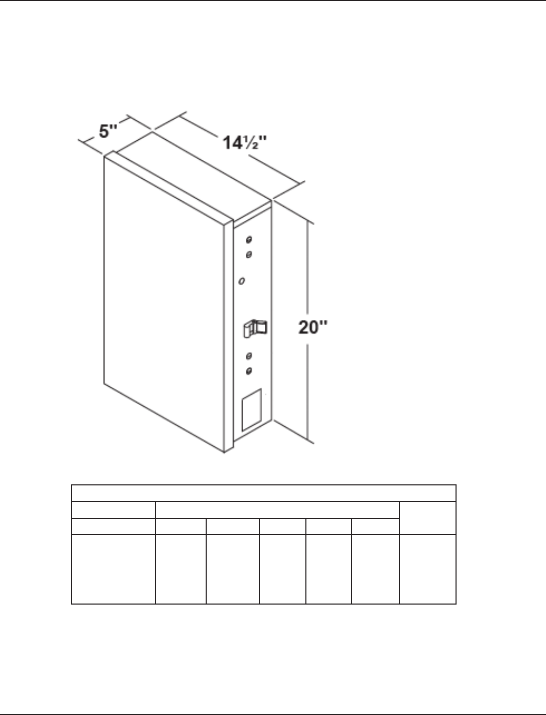
Section 7:
Enclosure Specifications
NEED ACTUAL ARTWORK — THIS IS JANDYNEED ACTUAL ARTWORK — THIS IS JANDY
Suitable listed breakers (purchase locally)
CIRCULT BREAKER FILLER
PLATE
MANUFACURER SINGLE DOUBLE TWIN QUAD GFCB
Cutler-Hammer
Murray
Siemens
Square-D
Thomas & Betts
BR
MP-T
QP
HOM
TB
BR
MP-T
QP
HOM
TB
BRD
MH-T
QT
HOMT
TBBD
BRD
MH-T
QT
HOMT
TBBD
BRD
MH-T
QT
HOMT
TBBD
BRFP
LX100FP
QF3
HOMFP
FP-1C-TB

50 I-Wave Installation Guide
Copyright © 2006 Intermatic, Inc.
Section 9:
Warranty
ONE YEAR LIMITED WARRANTY
If, within one (1) year from the date of purchase, this product fails due to defect in material or workmanship, Intermatic Incorporated will repair
or replace it, as its sole option, free of charge. This warranty is extended to the original household purchaser only and is not transferable. This
warranty does not apply to: (a) damage to units caused by accident, dropping, or abuse in handling, acts of God, or any negligent use; (b) units
which have been subject to unauthorized repair, opened, taken apart, or otherwise modified; (c) units not used in accordance with instructions; (d)
damages exceeding the cost of the product; (e) sealed lamps and/or lamp bulbs, LEDs, and batteries; (f) the finish on any portion of the product,
such as surface and/or weatheriong, as this is considered normal wear and tear; (g) transit damage, initial installation costs, removal costs, or
reinstallation costs.
INTERMATIC INCORPORATED WILL NOT BE LIABLE FOR INCIDENTAL OR CONSEQUENTIAL DAMAGES. SOME STATES DO NOT ALLOW THE
EXCLUSION OR LIMITATION OF INCIDENTAL DAMAGES, SO THE ABOVE LIMITATION OR EXCLUSION MAY NOT APPLY TO YOU. THIS WARRANTY
IS IN LIEU OF ALL OTHER EXPRESS OR IMPLIED WARRANTIES. ALL IMPLIED WARRANTIES, INCLUDING THE WARRANTY OF MERCHANTABILITY
AND THE WARRANTY OF FITNESS FOR A PARTICULAR PURPOSE, ARE HEREBY MODIFIED TO EXIST ONLY AS CONTAINED IN THIS LIMITED
WARRANTY, AMND SHALL BE OF THE SAME DURATION AS THE WARRANTY PERIOD STATE ABOVE. SOME STATES DO NOT ALLOW
LIMITATIONS ON THE DURATION OF AN IMPLIED WARRANTY, SO THE ABOVE LIMITATION MAY NOT APPLY TO YOU.
This warranty service is available by either (a) returning the product to the dealer from whom the unit was purchased, or (b) mailing the product,
along with proof of purchase, postage prepaid, to the authorized service center listed below. This warranty is made by: Intermatic Incorporated/
After Sales Service/7777 Winn Rd., Spring Grove, IL 60081-7000 <http://intermatic.com>. Please be sure to wrap the product securely to avoid
shipping damage.
Because of our commitment to continuing research and improvements, Intermatic Incorporated reserves the right to make changes, without notice,
in the specifications and material contained herein, and shall not be responsible for any damages, direct or consequential, caused by reliance on
the material presented.
WARRANTY REGISTRATION
Owner’s Name___________________________________ Signature_____________________________________________
Street Adddress_________________________________________ Date of Purchase ______________________________
City__________________________________ State ______ Zip ______________ Phone __________________________
Authorized Dealer _____________________________ Sales Rep ____________________________
City__________________________________ State _________ Zip ______________ Phone _______________________
How did you hear about our product? (Please check all that apply.)
___Pool Store Employee ___Pool Builder ___Pool Service ___Direct Mail Ad ___In-Store Display ___
Friend/Relative
___Magazine ___Newspaper ___Radio ___TV ___Catalog ___Other: _____________________________
To activate your warranty, please return this portion to:
Intermatic, Inc.
7777 Winn Road
Spring Grove, IL 60081
or by FAX: 815-675-7055

Nine: Warranty 51
Providing a brighter solution.™
Installation Notes
___________________________________________________________________________________
___________________________________________________________________________________
___________________________________________________________________________________
___________________________________________________________________________________
___________________________________________________________________________________
___________________________________________________________________________________
___________________________________________________________________________________
___________________________________________________________________________________
___________________________________________________________________________________
___________________________________________________________________________________
___________________________________________________________________________________
___________________________________________________________________________________
___________________________________________________________________________________
___________________________________________________________________________________
___________________________________________________________________________________
___________________________________________________________________________________

Intermatic, Inc.
7777 Winn Road
Spring Grove, Illinois 60081-9698
www.intermatic.com
Intermatic Customer Service: 815-675-7000
(8 a.m. through 4:30 p.m. CT, Monday through Friday)
©2006 Intermatic, Inc.
Printed in U.S.A. [code number]