Intermatic CA3500 Split-Duplex Receptacle User Manual CA3500
Intermatic Inc Split-Duplex Receptacle CA3500
Exhibit D Users Manual per 2 1033 b3
WARNING: Read instructions completely before installation and retain for future reference.
WARNING:
WARNING:
OTHER CAUTIONS:
For installation and/or use in accordance with appropriate electrical codes and regulations.
Consult a qualified electrician for installation and operation.
1. For remote operation, use with Z-Wave compatible control for wireless control from any location.
2. Disconnect power when servicing or changing load.
3. Use this device only with copper or copper clad wire.
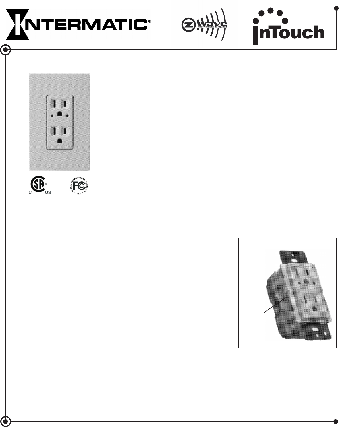
Model CA3500
Split-Duplex Receptacle
Specifications:
Ratings:
Colors:
Connections:
RF Information:
Network Information:
Local control via Activator Button
or Local Control via Current Sense
or Wireless RF Control
Includes white, ivory, and light almond
snap-on face plates.
Black-Line, White-Neutral,
Green-Ground
Minimum Range:
50ft indoor; 100ft outdoor
Frequency: 908.42 MHz
Mesh Network - Each line powered
node acts as a repeater to route
distant signals.
Data Rate: 9600 bits/second
Size: 232 Z-Wave™ Nodes
Operating Temperature Range:
32°F (0°C) to 104°F (40°C)
Power Consumption: 2.0W Max
125VAC, 50/60Hz
15A General Purpose Loads
INSTALLATION:
1. WARNING: TO AVOID FIRE, SHOCK, OR DEATH, TURN OFF POWER AT CIRCUIT BREAKER AND
TEST THAT POWER IS OFF BEFORE WIRING.
Operation:
2. For retrofit applications, remove wall plate and disconnect receptacle.
3. Refer to wiring diagram for proper connection of receptacle.
4. Check that all wire connections are secure.
5. Place all wires inside junction box. Install receptacle using (2) mounting screws furnished. Complete
installation with a decorator style wall-plate.
6. Reconnect your electrical power.
7. Press activator button to turn load on; press activator button to turn load off.
8. For programming instructions refer to the (158CA12789).InTouch Installer & Users Guide
The CA3500 Split-Duplex Receptacle is a Z-wave™ enabled device which is fully compatible with any Z-wave
enabled network. Z-wave enabled devices display the Z-wave logo and guarantee connectivity and
interoperability between devices. Each line powered node in a Z-wave network is designed to act as a
repeater forming a mesh network eliminating radio “dead spots” and providing the highest level of reliability.
- Multiple location On/Off control of receptacle when used with wireless accessory controls.
- “Local Control” feature senses user need for current and will automatically activate receptacle.
- Up-front activator switch always operates local load, does not require central control system.
Features
Faceplate Color Conversion
The frame and faceplate color of this device can be
converted to match interior design requirements.
Simply use one of the included color plates (white,
ivory, or light almond) and proceed as follows (please
note that the device must be removed from the junction
box to change the faceplate, follow the installation
instructions and warnings).
1. Select the color of the face you desire.
2. The frame has snaps on its sides. Using a small
screwdriver or thumbnail, gently remove the frame and
faceplate from the housing body.
3. Take the new frame and position it properly to the
housing body. Notice that the locking snaps will align in
only the proper direction. Line up the plastic snaps with
the slots in the housing body and snap into place.
4. The frame snaps in with an audible click. Ensure that
both snaps are secure. Replace the device in the
junction box following installation instructions.
The color conversion is complete.
Faceplate
Snap
FCC STATEMENT OF COMPLIANCE
WARNING! Changes or modifications not expressly approved by Intermatic Inc. could void the user’s authority to operate the
equipment.
This device complies with part 15 of the FCC rules. Operation of this device is subject to the following two conditions:
(1) This device may not cause harmful interference, and
(2) This device must accept any interference, including interference that may cause undesired operation.
NOTE: This equipment has been tested and found to comply with the limits for a Class B digital device, pursuant to Part 15 of the FCC Rules.
These limits are designed to provide reasonable protection against harmful interference in a residential installation. This equipment generates,
uses and can radiate radio frequency energy and, if not installed and used in accordance with the instructions, may cause harmful interference to
radio communications. However, there is no guarantee that interference will not occur in a particular installation. If this equipment does cause
harmful interference to radio or television reception, which can be determined by turning the equipment off and on, the user is encouraged to try to
correct the interference by one or more of the following measures:
-- Reorient or relocate the receiving antenna or device.
-- Increase the separation between the equipment and receiver.
-- Connect the equipment into an outlet on a circuit different from that to which the receiver is connected.
-- Consult the dealer or an experienced radio/TV technician for help.
This product is compatible with other Z-Wave enabled products™
Providing a Brighter Solution™
158CA12477REF
WIRELESS CONTROLS
TM
White
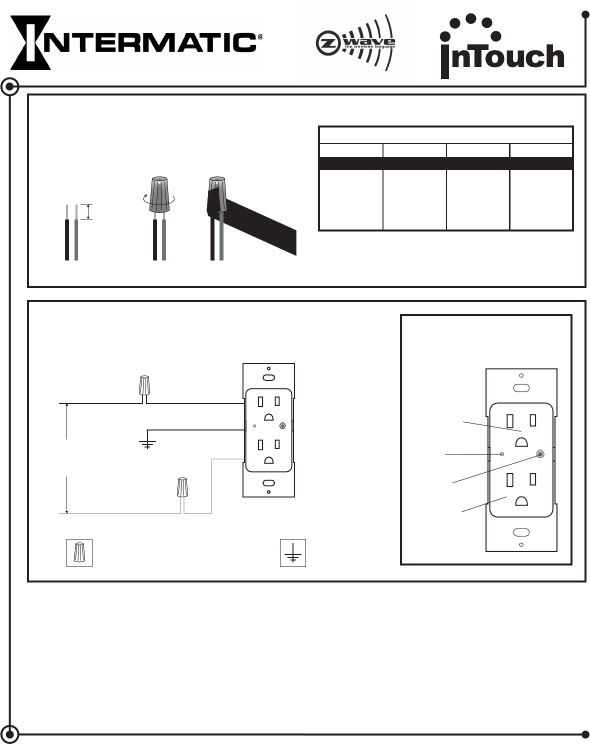
Standard Installation
Hot Black
Neutral
Wire Connector Ground
Green
120VAC
50/60 Hz
CA3500
Activator
Button
Hot
Receptacle
Controlled
Receptacle
Status
LED
This product is compatible with other Z-Wave enabled products™
LIMITED TEN YEAR WARRANTY
If within ten (10) years from date of purchase, this product fails due to a defect in material or workmanship, Intermatic Incorporated will repair or replace, at its
sole option. This warranty applies only to the original purchaser and is not transferable. This warranty excludes and this is disclaimed liability for labor for
removal of this product or reinstallation. The warranty does not apply to: (a) damage caused by accident, abuse, mishandling, dropping, acts of God, or any
negligent use; (b) units which have been subject to unauthorized repair, opened, taken apart, or otherwise modified; (c) units not used in accordance with
directions; (d) damages exceeding the cost of the product. Some states do not allow a limitation of damages, so the foregoing limitation may not apply to you.
This warranty gives you specific legal rights and you may have other rights that vary from state to state.
This warranty service is available by either (a) returning the product to the dealer from whom the unit was purchased, or (b) mailing postage prepaid to the
nearest authorized service center listed. Please be sure to wrap the product securely when mailing to avoid shipping damage. This warranty is made by:
Intermatic Incorporated, After Sales Service, 7777 Winn Road, Spring Grove, IL 60081-9698, 815-675-7000 www.intermatic.com
INTERMATIC INCORPORATED WILL NOT BE
LIABLE FOR INCIDENTAL OR CONSEQUENTIAL DAMAGES. THIS WARRANTY IS IN LIEU OF ALL OTHER EXPRESS OR IMPLIED WARRANTIES.
ALL IMPLIED WARRANTIES, INCLUDING THE WARRANTY OF MERCHANTABILITY AND THE WARRANTY OF FITNESS FOR A PARTICULAR
PURPOSE, ARE HEREBY MODIFIED TO EXIST ONLY AS CONTAINED IN THIS LIMITED WARRANTY, AND SHALL BE OF THE SAME DURATION AS
THE WARRANTY PERIOD STATED ABOVE.
Wire Connector Installation
Connect wires as follows:
Screw wire connectors on clockwise making sure no
bare conductors show below the wire connector.
Secure each connector with electrical tape.
Insert wires straight
then twist clockwise
Secure each connnector
with electrical tape
Strip wires to expose
3/8” of conductors
3/8”
For non-standard wiring applications, refer to
Wire Combination & Connector Chart
Yellow Wire Connector Combination Chart
1- #10 AWG
1 #12 AWG
or
2 #14 AWG
or
2 #16 AWG
+
1- #12 AWG
1to2#12AWG
or
1to3#14AWG
or
1to4#16AWG
+
1- #14 AWG
1to3#14AWG
or
1to4#16AWG
or
1to4#18AWG
+
1- #16 AWG
1to4#16AWG
or
1to4#18AWG
+
CA3500 Split
Duplex Receptacle
Providing a Brighter Solution™
WIRELESS CONTROLS
TM