Intermatic Ct2000 Instructions Owner S Manual
521287-Installationsheet 521287-InstallationSheet 521287-InstallationSheet 078275 Batch5 unilog cesco-content
2014-07-06
: Intermatic Intermatic-Ct2000-Instructions-Owner-S-Manual intermatic-ct2000-instructions-owner-s-manual intermatic pdf
Open the PDF directly: View PDF ![]() .
.
Page Count: 4
• Disconnectpoweratthecircuitbreaker(s)
ordisconnectswitch(es)beforebeginning
installationandbeforeservicing.
• Morethanonecircuitbreakeror
disconnectswitchmayberequiredto
de-energizetheequipmentbefore
servicing.
• Donotusethemanualoffpositionofthe
timerforequipmentservice.Always
disconnectthepoweratthecircuit
breaker(s)ordisconnectswitch(es).
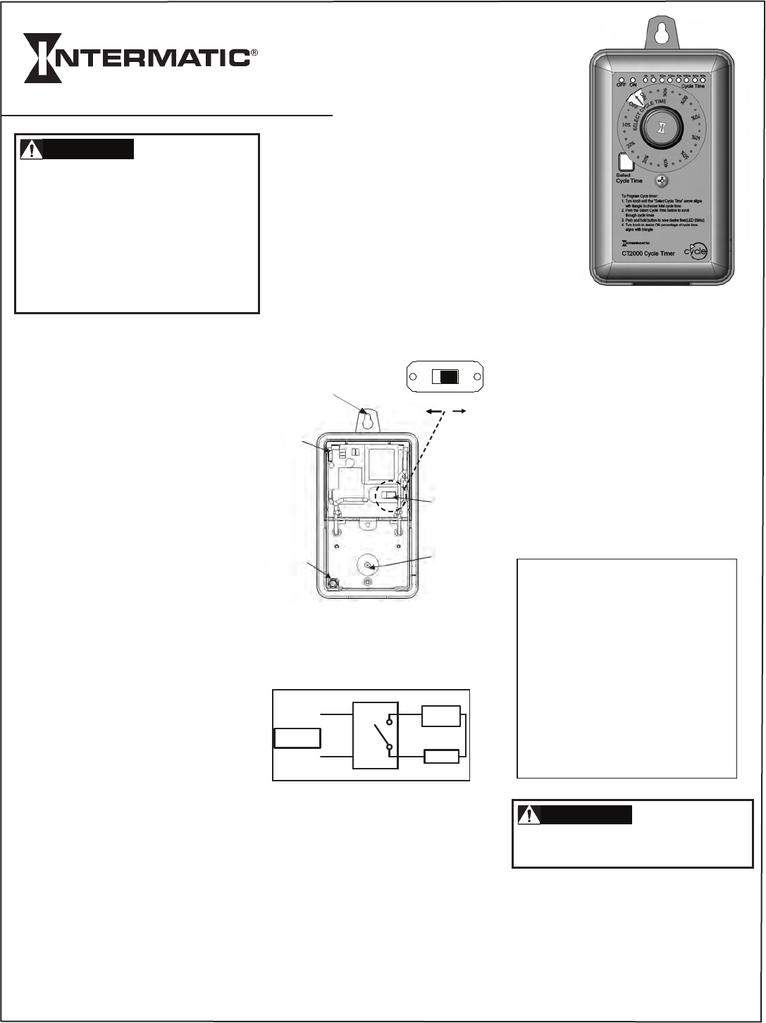
TheCT2000Timerprovidesrepetitivecycling
forfans,misters,foggers,feeders,process
equipmentandothershortcycleapplications.
Thetimerisfieldadjustableforapercentage
oftotalcycleduration.CycleTimes
(durations)canbesetfrom30secondstoa
maximumof4hrs.withONdurationsfrom1
secondupto232minutes.Thepercentageof
totalONtimeisselectedusingtherotary
knob,whichprovides30separatedetent
positionsforpreciseselection.Indicatorsare
providedforeachCycleTime.CycleTimes
are:30seconds,1,3,5,10,or30minutes,1
or4hours.
Powerinputtothetimermaybeanystandard
120or240volt60HzACsupply.Aninternal
switchallowsquickandeasyconfiguration.
NOTE:Timerisshippedin240Vposition.
Thetimerenclosureincludestwomounting
holeson5-3/16”centersandaknockoutfor
1/2”conduitconnection.
Safety Precautions
•Theconnectionandinstallationof
electricaldevicesmayonlybecarried
outbyaqualifiedelectrician.
•Interventionsinandchangestothe
devicewillvoidthewarranty.
•Observeyournationalregulationsand
therespectivesafetyprovisions.
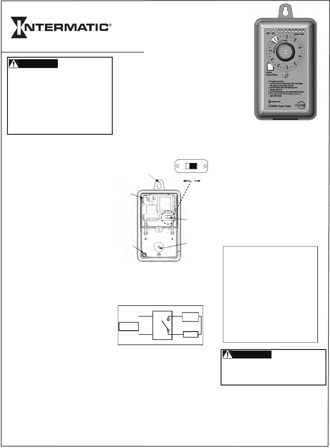
INSTALLATION
1.Determinedesiredmountinglocation.
2.Loosencoverscrew,liftoffcoverand
disconnectthecircuitboardcable.
3.Mounttimersecurelyusing1or2screws
ofappropriatelength,with#8mindia.
(screwsnotsupplied)Useadrilltoopenthe
lowerholeinbaseifnecessary.Thelower
holemustbesecuredwithascrewafter
opening.Tightenscrewsasrequired,butdo
notovertighten.
4.Connectconduithubstoconduitbefore
connectingthehubstothebracket.After
insertinghubsintobracket,carefullytighten
hublocknut.Donotover-torque.
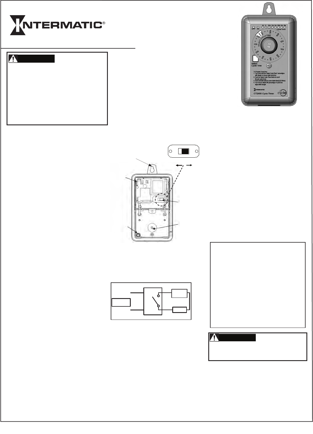
5.WireinaccordancewithNationalandLocal
Codes.Makesurethewiringconnectionsfor
ClockPowerareasshownfor120or240
voltsACinput.PositionSW1intheproper
positionfor120Vor240VClockPower
operation.(Timerisshippedin240Vposition.)
6.Makeloadconnectionsasshown.Note
thattheredwiresareconnectedtoisolated
relaycontactstoallowtheloadtobe
poweredfromadifferentcircuit/voltagethan
the“ClockPower”.Youmustsupplypower
tooneoftheRedwiresandconnecttheother
Redwiretoyourload.
7.Grounding:Terminateallgroundwiresto
thegroundlug/screwonthebracket.
8.Reversestep2toreplacecover.Besureto
reconnectthecircuitboardconnector.Secure
coverwithcoverscrew;donotovertighten.
9.Restorepowertotimeratdisconnector
breakerpanel.
CYCLE TIME SETUP
ToProgramCycleTimer:
1.Turnknobuntilthe“SelectCycleTime”
arrowalignswithtriangletochoosetotal
cycletime.
2.PushtheSelectCycleTimebuttontoscroll
throughcycletimes.
3.Pushandholdbuttontosavedesiredtime
(LEDBlinks).
4.Turnknobuntildesiredpercentageof
cycletimealignswithtriangle.
Turningknobtoany%positionwillinitiatea
newONperiodfortheselectedCycleTime.
Higherpercentagepositionsprovide
additionalONtime,andlessOFFtime,as
shownbelow.
ApermanentONandapermanentOFF
positionareprovidedtoallowmanual
overrideofthecycleatanytime.
DonotusethemanualOFFpositionfor
equipmentservice.Alwaysdisconnectpower
atthedisconnectswitch(es)orbreakerpanel.
TheOFFindicatorwillbesteadyREDinthe
OFFpositionandduringtheOFFportionof
thecycles.
TheONindicatorwillbesteadyGREENinthe
ONpositionandduringtheONportionofthe
cycles.
TheyellowCycleTimeindicatorwillbeON
exceptwheninthepermanentONorOFF
positions.
CT2000 SERIES
CYCLE PERCENTAGE TIMER
Cycle Time Selector ON Time OFF Time
Duration Knob %
30sec. 10% 3sec. 27sec.
30sec. 50% 15sec. 15sec.
30sec. 80% 24sec. 6sec.
10min. 10% 1min. 9min.
10min. 50% 5min. 5min.
10min. 80% 8min. 2min.
1hour 10% 6min. 54min.
1hour 50% 30min. 30min.
1hour 80% 48min. 12min.
4hours 10% 24min.216min.
4hours 50%120min.120min.
4hours 80%192min.48min.
Risk of Electric Shock
WARNING
Risk of Electric Shock
WARNING
SPECIFICATIONS
InputVoltage:120VACor240VAC,60Hz
Thistimerhasanenvironmentaloperating
temperaturerangeof-10˚C(14˚F)to+60˚C
(140˚F).
Theinputisprotectedforupto6000volt
3000amppowersurges.
Overalldimensions:31/2inchesx65/8
inchesx31/4inches.
Voltage Load N.O.Contact
240VAC GeneralPurpose 20A
120VAC Motor 1HP
240VAC Motor 2HP
240VAC Tungsten 5A
240VAC PilotDuty 470VA
277VAC Ballast 10A
28VDC Resistive 20A
CLOCK
POWER
120/240
VAC
BLK
WHT
RED
RED LOAD
LOAD
POWER
LINE
N/LINE
Upper
MountingHole
Lower
Mounting
Hole
SW1
120Vor240V
Circuit
Board
Connector
Ground
Screw
Location
SW1
120V 240V
• Desconectelaalimentaciónenel(losdisyuntor(es)
decircuitooel(losinterruptor(es)dedesconexión
antesdecomenzarlainstalaciónyderealizar
serviciosdemantenimiento.
• Másdeundisyuntordecircuitoodesconectarel
interruptorpuedesernecesariopara
desenergizarelequipoantesdedarleservicio.
• Nouselaposicióndeapagadomanualdel
temporizadorparadarleservicioalequipo.
Siempredesconectelaenergíadeel(los)
disyuntor(es)decircuitoodeel(los)
interruptor(es).
EltemporizadorCT2000proporcionaciclos
repetitivosparaventiladores,nebulizadores,
atomizadores,alimentadores,equiposdeproceso
yotrasaplicacionesdeciclobreve.El
temporizadorpuedeajustarseenelcampopara
obtenerunporcentajedeladuracióntotaldel
ciclo.LosTiemposdelCiclo(duraciones)se
puedenconfigurardesde30segundoshastaun
máximode4horas.conlasduracionesenla
posiciónONdesde1segundohasta232minutos.
Elporcentajedetiempototaldeencendidose
seleccionaconlaperillagiratoria,queofrece30
posicionescontopeseparadasparauna
selecciónexacta.Seproveenindicadorespara
cadaTiempodeCiclo.LosTiemposdeCicloson:
30segundos,1,3,5,10ó30minutos,1ó4
horas.
Laentradadealimentaciónaltemporizadorpuede
sercualquiersuministroestándarde120voltios
ó240voltiosde60HzdeCA.Uninterruptor
internopermitequelaconfiguraciónsearápiday
fácil.
NOTA:Eltemporizadorseenvíaenlaposiciónde
240V.
Elgabinetedeltemporizadorincluyedosorificios
demontajeencentrosde5-3/16”yunorificio
ciegode1/2"paralaconexióndeconductos.
Precauciones de seguridad
•Laconexióneinstalacióndedispositivos
eléctricossólosepuedehacerporpartede
unelectricistacalificado.
•Lasmanipulacionesyloscambiosdel
dispositivoanularánlagarantía.
•Respetelasreglamentacionesnacionalesy
lasdisposicionesdeseguridadrespectivas.
INSTALACIÓN
1.Determinelaubicacióndeseadaparael
montaje.
2.Aflojeeltornillodelacubierta,levantela
cubiertaydesconecteelcabledeltablerode
circuitos.
3.Montebieneltemporizadorcon1ó2tornillos
delongitudapropiada,conundiámetromínimo
del#8.(tornillosnoprovistos)Useuntaladro
paraabrirelorificioinferiorenlabasedeser
necesario.Elorificioinferiorsedebeasegurar
conuntornillodespuésdeabrirlo.Aprietelos
tornillossegúnseanecesario,perosinexcederse.
4.Conectelosconcentradoresalconductoantes
deconectarlosconcentradoresalacarcasa.
Despuésdeinsertarlosconcentradoresenla
carcasa,aprieteconcuidadolatuercadelos
concentradores.Noaprietedemasiado.
5.Coloqueelcableadodeacuerdoconlos
CódigosNacionalesyLocales.Asegúresedeque
lasconexionesdecablesparalaalimentacióndel
relojesténcomosemuestraparaunaentradade
120voltiosó240voltiosdeCA.ColoqueSW1en
laposiciónadecuadaparalaoperacióndelreloj
de120Vó240V.(Eltemporizadorseenvíaenla
posiciónde240V).
6.Realicelasconexionesdecargacomose
ilustra.Observequeloscablesdecolorrojose
conectanacontactosdereléaisladosparaquela
cargapuedaseralimentadaconotrocircuito/
voltajequelaalimentacióndelreloj.Debe
suministrarsealimentaciónaunodeloscables
rojosyconectarelotrocablerojoalacarga.
7.Puestaatierra:Conectetodosloscablesa
tierraenlacajaatierrayatornillealacarcasa.
8.Realicedemanerainversaelprocedimientodel
paso2paravolveracolocarlacubierta.
Asegúresedevolveraconectarelconectordel
tablerodecircuitos.Asegurelacubiertaconel
tornillocorrespondiente;noaprietedemasiado.
9.Restablezcalaalimentaciónaltemporizadoren
eltablerodeinterruptoresdedesconexiónolos
disyuntores.
CONFIGURACIÓN DEL TIEMPO DE CICLO
Paraprogramareltemporizadordeciclos:
1.Girelaperillahastaquelaflecha“Seleccionar
elTiempodeCiclo”sealineeconeltriángulopara
elegireltiempodeciclototal.
2.JaleelbotóndeTiempodeCiclopararecorrer
lostiemposdeciclo.
3.Presioneysostengaelbotónparaguardarel
tiempodeseado(LaluzLEDparpadea).
4.Girelaperillahastaqueelporcentajedeseado
deltiempodeciclosealineeconeltriángulo.
Girarlaperillaacualquierposiciónde%iniciará
unnuevoperiododeencendidoparaelTiempode
Cicloseleccionado.
Lasposicionesdeporcentajemásaltas
proporcionanmástiempodeencendido,ymenos
tiempodeapagado,comoseilustraa
continuación.
Sedisponedeunaposiciónpermanentede
encendidoyunaposiciónpermanentede
apagadoparapermitirlaanulaciónmanualdel
cicloencualquiermomento.
ElindicadordeapagadoestaráfijoenROJOenla
posicióndeapagadoyduranteeltiempode
apagadodelosciclos.
ElindicadordeencendidoestaráfijoenVERDEen
laposicióndeencendidoyduranteeltiempode
encendidodelosciclos.
ElindicadoramarillodelTiempodeCicloestará
encendidoexceptocuandoestéenlasposiciones
deencendidoyapagadopermanentes.
SERIE CT2000
TEMPORIZADOR DE PORCENTAJE DE CICLO
Tiempo de Selector Tiempo de Tiempo de
Ciclo Peirlla % encendido apagado
Duración
30seg. 10% 3seg. 27seg.
30seg. 50% 15seg. 15seg.
30seg. 80% 24seg. 6seg.
10min. 10% 1min. 9min.
10min. 50% 5min. 5min.
10min. 80% 8min. 2min.
1hora 10% 6min. 54min.
1hora 50% 30min. 30min.
1hora 80% 48min. 12min.
4horas 10% 24min.216min.
4horas 50% 120min.120min.
4horas 80% 192min.48min.
Riesgo de electrocución
WARNING
Riesgo de electrocución
WARNING
ESPECIFICACIONES
Voltajedeentrada:120VACó240VAC,60Hz
Estetemporizadortieneuntangode
temperaturaoperativaambientalde-10˚C
(14˚F)a+60˚C(140˚F).
Laentradaestáprotegidaparasobrecargas
deenergíadehasta6,000voltios,3,000
amperes.
Dimensionesgenerales:31/2pulgadasx6
5/8pulgadasx31/4pulgadas.
Voltaje Carga N.O.Contacto
240VAC Usogeneral 20A
120VAC Motor 1HP
240VAC Motor 2HP
240VAC Tungsteno 5A
240VAC Reléauxiliar 470VA
277VAC Balastra 10A
28VDC Resistivo 20A
RELOJ
ENERGÍA
120/240
VAC
NEGRO
BLANCO
ROJO
ROJO CARGA
CARGA
ENERGÍA
LÍNEA
N/LÍNEA
Superior
Oriciodemontaje
Inferior
Montaje
Oricio
SW1
120Vó240V
Circuito
Tablero
Conector
Conexión
atierra
Tornillo
Ubicación
SW1
120V 240V
Nouselaposicióndeapagadomanualparadarle
servicioalequipo.Siempredesconectela
alimentaciónenel(LOS)tablero(s)dedesconexióno
elpaneldedisyuntores.
• Débrancherl’alimentationauniveauduoudes
disjoncteursoudébrancherleoulesinterrupteurs
avantdedébuterl’installationoudeprocéderà
touteréparation.
• Plusd’undisjoncteurououinterrupteur
peuventêtrenécessairespouréteindre
l’équipementavantuneréparation.
• Nepasutiliserlapositionhorstension
manuellesurlaminuteriepouruneréparation
d’équipement.Toujoursdébrancherl’alimentation
auniveaududisjoncteuroudel’interrupteur.
LaminuterieCT2000fournituncyclerépétitif
pourlesventilateurs,lesnébulisateurs,les
brumisateurs,lesdoseurs,l’équipementde
traitementetdiversesautresapplicationsàcycle
court.Laminuterieestrégléeenfonctiondu
besoinpourunpourcentagedeladuréetotaledu
cycle.Lesduréesdecyclepeuventêtrerégléesà
partirde30secondesjusqu’àunmaximumde4
heuresavecdespériodessoustensiondeune(1)
secondejusqu’à232minutes.Lepourcentagede
tempstotalsoustensionestsélectionnéàl’aide
duboutonrotatiflequelcomporte30positionsà
encliquetagedistinctespourunesélectiontrès
précise.Destémoinslumineuxsontutiliséspour
chaqueduréedecycle.Lesduréesdecyclesont
de:30secondes,1,3,5,10ou30minutes,1ou
4heures.
L’alimentationàlaminuteriepeutêtrede120ou
de240voltsCA60Hz.Uncommutateurinterne
permetuneconfigurationrapideetfacile.
REMARQUE:Laminuterieestlivréedansla
position240V.
Leboîtierdelaminuteriecomportedeux(2)trous
demontageà53/16poaucentre,ainsiqu’une
alvéoledéfonçablede½popourlaconnexiondu
conduit.
Précautions de sécurité
•Laconnexionetl’installationde
dispositifsélectriquesdoiventêtre
effectuéesqueparunélectricienqualifié.
•Toutealtérationetmodificationau
dispositifannuleralagarantie.
•Respecterlesréglementationsnationaleset
lesprécautionsdesécurité.
INSTALLATION
1.Déterminerl’emplacementsouhaitédu
montage.
2.Dévisserlavisducouvercle,souleverle
couvercleetdébrancherlecâbleducircuit
imprimé.
3.Fixerlaminuterieenutilisantune(1)oudeux
(2)visdelongueurappropriéeayantaumoinsun
diamètren°8.(visnonfournies)Utiliserune
perceusepourouvrirletrouinférieuraubesoin.
Letrouinférieurdoitêtrereferméavecunevis
aprèssonouverture.Serrerlesviscommerequis,
maisnepastropserrer.
4.Effectuerleraccordementauconduitavant
celuiauboîtier.Aprèsl’insertiondu
raccordement,serrerl’écroudeblocageavec
précaution.Nepastropserrer.
5.Brancherselonlescodeslocauxetnationaux.
Fairelesconnexionspourl’alimentationde
l’horlogecommeillustrépouruneentréede120
ou240voltsc.a.MettreCOM1enposition
appropriéeselonl’alimentationdefonctionnement
de120oude240voltsdel’horloge.(Laminuterie
estlivréedanslaposition240V.)
6.Relierlesbornesdesortiecommeillustré.
Remarquerquelesfilsrougessontconnectésà
descontactsderelaisisolésafindepermettreàla
charged’êtrealimentéeparuncircuitouune
tensionautrequeceluiutilisépourl’horloge.Il
fautalimenterundesfilsrougesetbrancher
l’autreàlacharge.
7.Miseàlaterre:Connectertouslesfilsdemise
àlaterreàlavis/bornedemiseàlaterresurle
boîtier.
8.Procéderdansl’ordreinversedel’étape2pour
reposerlecouvercle.S’assurerderebrancherle
connecteurducircuitimprimé.Fixerlecouvercle
aveclavis;nepastropserrer.
9.Rétablirlecourantauniveaududisjoncteurou
del’interrupteur.
CONFIGURATION DE LA DURÉE DU CYCLE
Pourprogrammerladuréeducycle:
1.Tournerleboutonjusqu’àcequelaflèchede
sélectiondeladuréeducycle(SelectCycleTime)
s’aligneavecletrianglepoursélectionnerladurée
totaleducycle.
2.Pousserleboutondesélectiondeladuréedu
cyclepourfairedéfilerlesduréesdecycle.
3.Pousseretmaintenirleboutonpour
sauvegarderladuréesouhaitée(DELclignote).
4.Tournerleboutonjusqu’àcequele
pourcentagesouhaitédeladuréeducycle
s’aligneavecletriangle.
Tournerleboutonàn’importequelpourcentage
deposition,initialiseraunenouvellepériodede
tensionpourlasélectiondeduréeducycle.
Unpourcentagedepositionplusélevéfournitune
duréesoustensionsupplémentaireetunedurée
pluscourtehorstension,commeillustré
ci-dessous.
Unepositionpermanentesoustensionetdeux
positionspermanenteshorstensionsontfournies
pourpermettreuneinterruptionmanuelledu
cycleentouttemps.
Tensionlorsdel’entretiend’équipment.Toujours
débrancherl’alimentationauniveaududisjoncteur
oudel’interrupteur.
LetémoinOFF(Horstension)seraallumé
ROUGEdanslapositionhorstensionet
pendantlapériodehorstensiondescycles.
LetémoinONseraalluméVERTdansla
positionsoustensionetpendantlapériode
soustensiondescycles.
Letémoinjaunedeladuréeducycles’allumera
sauflorsqu’enpositionON(soustension)ou
OFF(horstension).
Série CT2000
MINUTERIE À POURCENTAGE DE CYCLE
Durée de Sélecteur Durée sous Durée hors
Cycle de la Bouton % Tension Tension
Minuterie
30s 10% 3s 27s
30s 50% 15s 15s
30s 80% 24s 6s
10min. 10% 1min. 9min.
10min. 50% 5min. 5min.
10min. 80% 8min. 2min.
1heure 10% 6min. 54min.
1heure 50% 30min. 30min.
1heure 80% 48min. 12min.
4heures 10% 24min.216min.
4heures 50% 120min. 120min.
Risque de choc électrique
WARNING
Risque de choc électrique
WARNING
SPÉCIFICATIONS
Tensiond’entrée:120ou240voltsc.a.,60Hz
Laplagedetempératureambiantede
fonctionnementdecetteminuteriesesitue
entre-10˚C(14˚F)et60˚C(140˚F).
L’entréeestprotégéecontrelessurtensions
jusqu’à6000voltset3000ampères.
Dimensionshorstout:31/2poucesx65/8
poucesx31/4pouces.
Tension decharge TypedeContacts
240voltsCA Usagepolyvalent 20A
120voltsCA Moteur 1HP
240voltsCA Moteur 2HP
240voltsCA Tungstène 5A
240voltsCA Commandepilote 470VA
277voltsCA Ballast 10A
28voltsCC Résistif 20A
HORLOGE
ALIMENTATION
120/240
volts
CA
NR
BL
ROUGE
ROUGE
TENSION
TENSION
ALIMENTA-
TION
CIRCUIT
CIRCUIT/N
Troudemontage
supérieur
Trou
demontage
inférieur
COM1
120Vou
240V
Circuit
Imprimé
Connecteur
Miseàla
terreVis
Emplace-
\ment
SW1
120V 240V

Intermatic Plaza, Spring Grove, Illinois 60081-9698 www.intermatic.com ©Copyright 2009 Intermatic Inc.
158--00934
INTERMATIC INCORPORATED
Limited One Year Warranty
If within the warranty period specified, this product fails due to a defect in material or workmanship, Intermatic Incorporated will repair or replace it, at its sole
option, free of charge. This warranty is extended to the original household purchaser only and is not transferable. This warranty does not apply to: (a) damage to
units caused by accident, dropping or abuse in handling, acts of God or any negligent use; (b) units which have been subject to unauthorized repair, opened, taken
apart or otherwise modified; (c) units not used in accordance with instructions; (d) damages exceeding the cost of the product; (e) sealed lamps and/or lamp bulbs,
LED’s and batteries; (f) the finish on any portion of the product, such as surface and/or weathering, as this is considered normal wear and tear; (g) transit damage,
initial installation costs, removal costs, or reinstallation costs.
INTERMATIC INCORPORATED WILL NOT BE LIABLE FOR INCIDENTAL OR CONSEQUENTIAL DAMAGES. SOME STATES DO NOT ALLOW THE
EXCLUSION OR LIMITATION OF INCIDENTAL OR CONSEQUENTIAL DAMAGES, SO THE ABOVE LIMITATION OR EXCLUSION MAY NOT APPLY TO
YOU. THIS WARRANTY IS IN LIEU OF ALL OTHER EXPRESS OR IMPLIED WARRANTIES. ALL IMPLIED WARRANTIES, INCLUDING THE WARRANTY OF
MERCHANTABILITY AND THE WARRANTY OF FITNESS FOR A PARTICULAR PURPOSE, ARE HEREBY MODIFIED TO EXIST ONLY AS CONTAINED IN
THIS LIMITED WARRANTY, AND SHALL BE OF THE SAME DURATION AS THE WARRANTY PERIOD STATED ABOVE. SOME STATES DO NOT ALLOW
LIMITATIONS ON THE DURATION OF AN IMPLIED WARRANTY, SO THE ABOVE LIMITATION MAY NOT APPLY TO YOU.
This warranty service is available by either (a) returning the product to the dealer from whom the unit was purchased or (b) completing a warranty claim online at
www.intermatic.com. This warranty is made by: Intermatic Incorporated, Customer Service 7777 Winn Rd., Spring Grove, Illinois 60081-9698. For warranty service
go to: http://www.Intermatic.com or call 815-675-7000.
Garantía Limitada De Un Año
Si en el plazo especificado por la garantía, el producto falla debido a un defecto de material o mano de obra, Intermatic Incorporated lo reparará o reemplazará,
a opción propia, de forma gratuita. Esta garantía se aplica solamente al comprador particular original y no es transferible. Esta garantía no se aplica en los casos
siguientes: (a) daños en unidades causados por accidente, caídas o abuso durante su manipulación, fuerza mayor o cualquier uso negligente; (b) unidades
que hayan sido sometidas a una reparación no autorizada, abiertas, desmontadas o modificadas de otra forma; (c) unidades que no se hayan usado según las
instrucciones; (d) daños que excedan el costo del producto; (e) lámparas selladas y bombillas, LED y pilas; (f) el acabado de cualquier parte del producto, tal
como la superficie y el desgaste debido a la intemperie, ya que esto se considera como un desgaste natural; (g) daños durante el transporte, costos de instalación
iniciales, costos de desmontaje o costos de reinstalación.
INTERMATIC INCORPORATED NO SERÁ RESPONSIBLE DE LOS DAÑOS EMERGENTES O CONSECUENTES. ALGUNOS ESTADOS NO PERMITEN LA
EXCLUSIÓN O LIMITACIÓN DE LOS DAÑOS EMERGENTES O CONSECUENTES, POR LO QUE ES POSIBLE QUE NO SE APLIQUE EN SU CASO LA
LIMITACIÓN O EXCLUSIÓN ANTERIOR. ESTA GARANTÍA SUSTITUYE LAS DEMÁS GARANTÍAS EXPLÍCITAS O IMPLÍCITAS. TODAS LAS GARANTÍAS
IMPLÍCITAS, INCLUIDA LA GARANTÍA DE COMERCIABILIDAD Y LA GARANTÍA DE IDONEIDAD PARA CIERTO FIN, SE MODIFICAN AQUÍ PARA EXISTIR
SÓLO SEGÚN ESTÁN CONTENIDAS EN ESTA GARANTÍA LIMITADA, Y DEBEN TENER LA MISMA DURACIÓN QUE EL PERÍODO DE GARANTÍA
INDICADO ARRIBA. ALGUNOS ESTADOS NO PERMITEN LIMITACIONES DE LA DURACIÓN DE UNA GARANTÍA IMPLÍCITA, POR LO QUE ES POSIBLE
QUE LA LIMITACIÓN ANTERIOR NO SE APLIQUE EN SU CASO.
Este servicio de garantía está disponible mediante (a) la devolución del producto al distribuidor al que se compró la undidad o (b) terminando una demanda de la
garantía en línea en www.intermatic.com. Esta garantía es provista por: Intermatic Incorporated/Customer Service/7777 Winn Rd., Spring Grove, Illinois 60081-
9698/815-675-7000 http://www.intermatic.com
Garantie Limitée D’un An
Si, dans la période de la garantie spécifiée, ce produit s’avère défectueux pour vice de matériau ou de fabrication, Intermatic Incorporated le réparera ou le
remplacera, la décision appartenant Intermatic Incorporated, sans frais. Cette garantie ne concerne que l’acheteur initial et n’est pas transférable. Cette garantie
ne couvre pas : (a) dommages occasionnés par accident, chute ou abus lors de manipulations, cas fortuits ou toute négligence ; (b) unités ayant subi à des
réparations non autorisées, ouvertes, démontées ou modifiées d’une quelconque façon ; (c) unités qui ne sont pas utilisées conformément aux instructions ;
(d) dommages supérieurs au coût du produit ; (e) éclairage scellé et/ou ampoule, DEL et batteries ; (f) la finition d’une partie du produit, telle que les rayures de
surface et/ou le vieillissement climatique qui sont considérés comme une usure normale ; (g) dommages ayant lieu pendant le transport, frais initiaux d’installation,
de désinstallation ou de réinstallation.
INTERMATIC INCORPORATED N’ENDOSSE AUCUNE RESPONSABILITÉ QUANT AUX DOMMAGES ACCESSOIRES OU INDRECTS. CERTAINES
PROVINCES NE PERMETTENT PAS D’EXCLUSIONS OU DE LIMITATIONS AUX DOMMAGES ACCESSOIRES OU CONSÉCUTIFS, LA LIMITE
INDIQUÉE CI-DESSUS PEUT NE PAS VOUS CONCERNER. CETTE GARANTIE CI-PRÉSENTES REMPLACE TOUTES AUTRES GARANTIES
EXPRESSES OU TACITES. TOUTES LES GARANTIES TACITES Y COMPRIS LA GARANTIE DE COMMERCIALISATION ET CELLE D’ADAPTABILITÉ
À DES FINS PARTICULIÈRES SONT MODIFIÉES CI-PRÉSENTES POUR N’EXISTER QUE TELLES QUELLES DANS CETTE GARANTIE LIMITÉE ET
AURONT LA MÊME DURÉE DE VALIDITÉ QUE LA PÉRIODE DE GARANTIE INDIQUÉE CI-DESSUS. CERTAINES PROVINCES NE PERMETTENT PAS
DE LIMITATIONS AUX TERMES DE LA DURÉE DE LA GARANTIE TACITE, LA LIMITE INDIQUÉE CI-DESSUS PEUT NE PAS VOUS CONCERNER.
Ce service sous garantie est disponible soit (a) en retournant le produit au dépositaire où vous avez acheté l’appareil, ou (b) terminant une réclamation de garantie
sur la ligne à www.intermatic.com. Cet garantie fait par: Intermatic Incorporated/Customer Service/7777 Winn Rd., Spring Grove, Illinois 60081-9698/815-675-7000
http://www.intermatic.com
FCC STATEMENT
NOTE: This equipment has been tested and found to comply with the limits for a Class
B digital device, pursuant to Part 15 of the FCC Rules. These limits are designed to
provide reasonable protection against harmful interference in a residential installation.
This equipment generates, uses and can radiate radio frequency energy and, if not
installed and used in accordance with the instructions, may cause harmful interference
to radio communications. However, there is no guarantee that interference will not
occur in a particular installation. If deteremined by turning the equipment off and on,
the user is encouraged to try to correct the interference by one or more of the following
measures:
• Reorientorrelocatethereceivingantennaordevice.
• Increasetheseparationbetweentheequipmentandreceiver.
• Connecttheequipmentintoanoutletonacircuitdifferentfromthattowhichthe
receiver is connected.
• Consultthedealeroranexperiencedradio/TVtechnicianforhelp.
DECARACIÓN DE LA FCC
NOTA: Este equipo ha sido probado y ha demostrado cumplir con los límites para
dispositivos digitales Clase B de acuerdo con la parte 15 de las normas de la FCC.
Estos límites se han diseñado a fin de proporcionar na protección razonable contra
interferencias dañias en las áreas residenciales. Este euipo genera, utiliza y puede
irradiar energía de radiofrecuencia, y si no es instalado y utilizdo de acuerdo con las
instrucciones, puede causar interferencias dañias en las comunicaciones por radio. Sin
embargo, no hay garantía de que no ocurran interferencias en una determinada insta-
lación. Si este equipo causa interferencias dañías en la recepción de radio o televisión,
lo cual se puede determinar apagando y encendiendo el equipo, el usuario tendrá que
corregir estas interferencias con una o varias de las siguientes medidas:
• Reorienteoubiqueenotrolugarlaantenareceptoraoeldispositivo.
• Aumentelaseparaciónentreelequipoyelreceptor.
• Conecteelequipoaltomacorrientedeuncircuitoeléctricodistintoalqueesté
conectado el receptor.
• Consultealdistribuidorounténicoderedio/TVconexperienciaparaobtener
asistencia.
Federal de Comunicaciones (FCC)
REMARQUE:Cematérielaétévériéetaétéreconnuconformeauxlimitesd’undispositif
numériquedeclasseB,selonl’article15desrèglementsdelaFCC.Cesrèglementssont
conçuspouroffriruneprotectionraisonnablecontred’éventuellesinterférencesnuisibles
lorsd’uneinstallationrésidentielle.Cematérielémet,utiliseetpeutdiffuserdesfréquences
radioqui,s’iln’estpasinstalléetutiliséconformémentauxdirectivesci-après,peuvent
engendrerdesinterférencesnuisiblesdanslescommunicationsradios.Toutefois,iln’ya
pasdegarantiequ’uneinterférencenesurviendrapasdansuneinstallationparticulière.
Sicetinstrumentproduitdesinterférencesnuisiblesàlaréceptiondelaradiooudela
télévision,cequipeutêtredéterminéenmettantsoustensionethorstensionl’instrument,
l’usagerestinvitéàessayerdelescorrigerenappliquantl’unedesmesuressuivantes.
Redirigerourepositionnerl’antennederéceptionouledispositif.•
Augmenterladistanceentrelematérieletlerécepteur.•
Brancherlematérielàlaprised’uncircuitdifférentdurécepteur.•
Consulterleconcessionnaireouuntechnicienqualiéenradioettélévision.•
