Intermatic PE000953 Hand Held Transceiver User Manual Exhibit D Users Manual per 2 1033 b3
Intermatic Inc Hand Held Transceiver Exhibit D Users Manual per 2 1033 b3
Exhibit D Users Manual per 2 1033 b3


2 Multi-Wave PE653-PE953 Installation Guide
Copyright © 2010 Intermatic, Inc.
Important Safety Instructions
All electrical work must be performed by a licensed electrician and conform to all national, state,
and local codes. When installing and using this electrical equipment, basic safety precautions
should always be followed, including the following:
DANGER: To reduce the risk of injury, do not remove the suction fittings of your spa or hot tub.
Never operate a spa or hot tub if the suction fittings are broken or missing. Never replace a
suction fitting with one rated less than the flow rate marked on the equipment assembly.
WARNING: Prolonged immersion in hot water may induce hyperthermia. Hyperthermia occurs
when the internal temperature of the body reaches a level several degrees above the normal
body temperature of 98.6°F. The symptoms of hyperthermia include dizziness, fainting,
drowsiness, lethargy, and an increase in the internal temperature of the body. The effects of
hyperthermia include: 1) unawareness of impending danger; 2) failure to perceive heat; 3)
failure to recognize the need to exit spa; 4) physical inability to exit spa; 5) fetal damage in
pregnant women; 6) unconsciousness resulting in a danger of drowning.
WARNING: To Reduce the Risk of Injury —
The water in a spa should never exceed 104°F (40°C). Water temperatures between 100°F •
(38°C) and 104°F (40°C) are considered safe for a healthy adult. Lower water temperatures are
recommended for young children and when spa use exceeds 10 minutes.
Since excessive water temperatures have a high potential for causing fetal damage during •
the early months of pregnancy, pregnant or possibly pregnant women should limit spa water
temperatures to 100°F (38°C).
Before entering a spa or hot tub, the user should measure the water temperature with an •
accurate thermometer since the tolerance of water temperature-regulating devices varies.
The use of alcohol, drugs, or medication before or during spa or hot tub use may lead to •
unconsciousness with the possibility of drowning.
Obese people and people with history of heart disease, low or high blood pressure, •
circulatory system problems, or diabetes should consult a physician before using a spa.
People using medication should consult a physician before using a spa or hot tub since some •
medication may induce drowsiness while other medication may affect heart rate, blood
pressure, and circulation.
WARNING: Risk of electric shock – Install the control center at least five (5) feet (152.4cm)
from the inside wall of the pool and/or hot tub using non-metallic plumbing. Canadian
installations must be at least three (3) meters from the water.

Safety 3
Providing a brighter solution.™
• Children should not use spas or hot tubs without adult supervision.
Do not use spas or hot tubs unless all suction guards are installed to prevent body and hair •
entrapment.
People using medications and/or having an adverse medical history should consult a •
physician before using a spa or hot tub.
People with infectious diseases should not use a spa or hot tub.•
To avoid injury, exercise care when entering or exiting the spa or hot tub.•
Do not use drugs or alcohol before or during the use of a spa or hot tub to avoid •
unconsciousness and possible drowning
Pregnant or possibly pregnant women should consult a physician before using a spa or hot •
tub.
Water temperature in excess of 100°F (38°C) may be injurious to your health.•
Before entering a spa or hot tub measure the water temperature with an accurate •
thermometer.
Do nut use a spa or hot tub immediately following strenuous exercise.•
Prolonged immersion in a spa or hot tub may be injurious to your health.•
Do not permit any electric appliance (such as a light, telephone, radio, or television) within 5 •
feet (1.5m) of a spa or hot tub.
The use of alcohol, drugs or medication can greatly increase the risk of fatal hyperthermia in •
hot tubs and spas.
Water temperature in excess of 100°F (38°C) may be hazardous to your health.•
WARNING: To reduce the risk of electrical shock, connect the grounding terminal in the
metal enclosure to the grounding terminal of your electric service or supply panel with a
continuous copper conductor having green insulation and one that is equivalent in size to the
circuit conductors supplying this equipment. In addition, a second wire connector should be
bonded with a no. 8 AWG (4.115mm) copper wire to any metal ladders, water pipes, or other
metal within five (5) feet (1.52m) of the tub.
WARNING: A ground-fault circuit-interrupter must be provided if this device is used to control
underwater lighting fixtures. The conductors on the load side of the ground-fault circuit-
interrupter shall not occupy conduit, boxes or enclosures containing other conductors unless
the additional conductors are also protected by a ground-fault circuit-interrupter. Refer to
local codes for complete details.

4 Multi-Wave PE653-PE953 Installation Guide
Copyright © 2010 Intermatic, Inc.
Contents
Important Safety Instructions ...........................................................................................................2
Section 1: System Overview .........................................................................................................8
Additional Detail on Key Components .........................................................................................9
Hand-Held Controller (PE953) ................................................................................................9
24-Volt Valve Actuator (PE24VA) ............................................................................................9
Water Temperature Sensor (PA122) .........................................................................................9
24-Volt Valve/Pump Switch (P4243ME) ................................................................................10
Optional — Freeze (Air Temperature) Sensor (178PA28A) ....................................................10
Section 2: Plumbing Examples ....................................................................................................11
For Pool and Spa Combo Installations ........................................................................................11
For Booster Pump Pool Cleaner Installations...............................................................................11
For Non-Booster Pump Pool Cleaner Installations.......................................................................12
Section 3: Installing and Wiring the PE653 Receiving Device ....................................................13
Ratings .......................................................................................................................................13
Wiring Instructions .....................................................................................................................14
Power Connections ...............................................................................................................14
Upper Terminal Connections .................................................................................................15
Installation Instructions .........................................................................................................15
List of Wiring Diagrams .........................................................................................................16
Variable-Speed Pumps ...............................................................................................................17
240V Variable-Speed Pump ...................................................................................................17
1-Speed Pumps ..........................................................................................................................18
120V 1-speed pump ..............................................................................................................18
120V 1-speed pump + any four 120 VAC auxiliary equipment ..............................................19
120V 1-speed pump + 120 VAC blower or lights + 120V booster pump +
120V actuator + heater ....................................................................................................20
120V 1-speed pump + 120V blower + 120V lights + 120V actuator + heater ........................21
240V Pumps ..............................................................................................................................22
240V 1-speed pump ..............................................................................................................22
240V 1-speed pump + any four 240 VAC auxiliary equipment ..............................................23
240V 1-speed pump + 240V blower + 240V booster pump + 240V actuator + heater ...........24
240V 1-speed pump + 120V lights + 120V blower + 240V actuator + heater ........................25
240V 2-Speed Pump .............................................................................................................26
240V 2-speed pump + any three 240VAC auxiliary equipment .............................................27
240V 2-Speed pump + any 3 120 VAC auxiliary equipment ..................................................28
240V 2-Speed pump + 240V Booster Pump + 240V Actuator + Heater ................................29
240V 2-speed pump + 120V lights + 240V blower + heater ..................................................30
240V 2-speed pump + 240V blower + 240V actuator + heater ..............................................31
240V 2-speed pump + 240V booster pump + 240V blower + heater .....................................32
240V 2-speed pump + 240V booster pump + 120V light + heater .........................................33
240V 2-speed pump + 240V booster pump + other 120 VAC equipment + heater .................34

Contents 5
Providing a brighter solution.™
Low-Voltage Wiring ...................................................................................................................35
Water Temperature Sensor .....................................................................................................35
Freeze/Air Temperature Sensor ...............................................................................................35
Communications to a Variable-Speed Pump .........................................................................36
Motorized Valve Actuator Connection and Synchronizing .....................................................36
Fireman’s Switch Connection .....................................................................................................37
Connection for Jandy Heaters ................................................................................................37
Connection for Raypak Heaters .............................................................................................38
Connection for Hayward Heaters ..........................................................................................38
Connection for Pentair Heater ...............................................................................................39
Connection for Sta-Rite / Pentair Heater with DDTC ..............................................................40
Section 4: Programming the PE953 Hand-Held Controller .........................................................41
Overview ...................................................................................................................................41
Creating a Network Connection between the Hand-Held Controller and
the PE653 Receiving Device .................................................................................................41
Deleting Any Existing Programming .......................................................................................41
Linking the Hand-Held Controller to the PE653 Receiving Device .........................................43
Configuring for a 1-Speed or 2-Speed Pump ...............................................................................44
Calibrating Pool, Spa and Air Temperature Settings .....................................................................44
Configuring for a Booster (Cleaner) Pump ..................................................................................45
Configuring the Fireman Switch Time Interval .............................................................................46
Setting the Time of Day ..............................................................................................................47
Setting Up Schedules .................................................................................................................47
Configuring the Freeze Temperature (optional) ...........................................................................48
Configuring for a Variable Speed Pump (optional) ......................................................................49
Testing Z-Wave Reception ..........................................................................................................50
Moving the Antenna to a Better Location ...............................................................................50
Labeling for the PE653 Screen ...............................................................................................51
Labeling for the Z-Wave Screen .............................................................................................51
Labeling for the Variable-Speed Pump Screen ........................................................................51
Labeling for the PE650 Screen ...............................................................................................51
Section 5: Everyday Use of the Hand-Held Controller ...............................................................52
Controlling the PE653 Receiving Device ....................................................................................53
Operating Programmed Functions .........................................................................................53
Changing between Pool and Spa ...........................................................................................53
Setting Pool and Spa Temperatures.........................................................................................54
Controlling a Variable-Speed Pump ............................................................................................54
Naming the Speeds ...............................................................................................................54
Changing Pump Speeds .........................................................................................................55
Controlling Z-Wave Devices ......................................................................................................55
Controlling PE650 Functions ......................................................................................................56
Changing Batteries in the Hand-Held Controller ........................................................................56
Manually Turning Equipment On and Off ..............................................................................57

6 Multi-Wave PE653-PE953 Installation Guide
Copyright © 2010 Intermatic, Inc.
Section 6:Advanced Features ......................................................................................................58
Configuring Two or More Hand-Held Controllers ..................................................................58
Changing a Secondary Remote Control into a Primary Control ..............................................60
Including the PE953 Controller into a non-Multi-Wave (other manufacturer’s) network. ........61
Section 7:Programming for Use with Z-Wave Home Control Devices ........................................62
Deleting Any Existing Programming .......................................................................................62
Including Z-Wave Devices into the Network .........................................................................63
Including the PE653 Receiver onto a non-Multi-Wave remote controller ...............................63
Adding Z-Wave Devices to Scenes for Everyday Control ........................................................64
Renaming a Scene .................................................................................................................65
Removing Z-Wave Devices from Scenes ................................................................................66
Removing Z-Wave Devices from a Network ..........................................................................66
Setting Up Z-Wave Associations with Capable Devices ........................................................67
Removing Z-Wave Devices from an Association ...................................................................69
Section 8:Using the PE953 with the PE650 Receiving Device .....................................................70
Linking the PE953 Hand-Held Controller with the PE650 Receiving Device ..........................70
Section 9: Checking Out and Verifying the System .....................................................................71
Section 10: Troubleshooting ......................................................................................................75
Section 11: Appendix ................................................................................................................80
Glossary of Z-Wave Terminology ................................................................................................80
FCC Statement ...........................................................................................................................81
Section 12: Warranty .................................................................................................................82

7
Providing a brighter solution.™
Notes
________________________________________________________________________________________________
________________________________________________________________________________________________
________________________________________________________________________________________________
________________________________________________________________________________________________
________________________________________________________________________________________________
________________________________________________________________________________________________
________________________________________________________________________________________________
________________________________________________________________________________________________
________________________________________________________________________________________________
________________________________________________________________________________________________
________________________________________________________________________________________________
________________________________________________________________________________________________
________________________________________________________________________________________________
________________________________________________________________________________________________
________________________________________________________________________________________________
________________________________________________________________________________________________
________________________________________________________________________________________________
________________________________________________________________________________________________
________________________________________________________________________________________________
________________________________________________________________________________________________
________________________________________________________________________________________________
________________________________________________________________________________________________
________________________________________________________________________________________________
________________________________________________________________________________________________
________________________________________________________________________________________________
________________________________________________________________________________________________
________________________________________________________________________________________________
________________________________________________________________________________________________
________________________________________________________________________________________________
________________________________________________________________________________________________
________________________________________________________________________________________________
8 Multi-Wave PE653-PE953 Installation Guide
Copyright © 2010 Intermatic, Inc.
Section 1:
System Overview
The Intermatic Multi-Wave Pool/Spa PE653RC Wireless Control System brings wireless control to
a new level of simplicity and affordability. The following features make the system distinctive:
Easy to Use — with simple, push button controls and a clear, easy-to-read display panel•
Everything You Need — includes the functionality and control called for in nearly every •
installation.
Dependable — with Z-Wave• ® technology that lets you expand your system with
inexpensive repeaters that plug into available electrical outlets to help extend the RF signal
range of the entire system. Z-Wave technology eliminates intermittent signal problems
experienced with many other systems.
Cost Efficiency — a superior system, easier to install and maintain, with better •
dependability, and at a cost that’s competitive with any other system available.
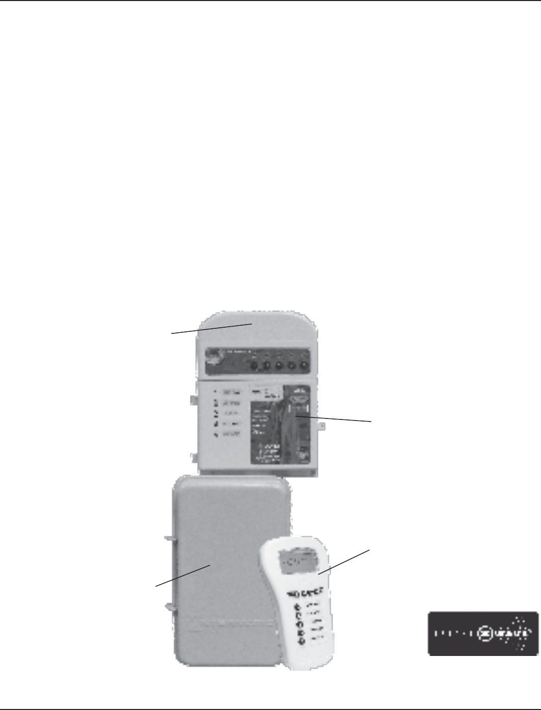
The standard configuration for the Multi-Wave PE653RC Pool/Spa Wireless Control System
configuration is shown in Figure 1-1. You can order individual components for a custom
configuration or system as indicated.
Z-Wave is a registered trademark of
Sigma Designs and/or its subsidiaries.
Figure 1-1
Weatherproof outdoor enclosure
can be mounted directly to an
existing enclosure.
Antenna can be remotely located
using a Standard Cat 5 Ethernet
cable with RJ45 plugs.
Terminals for two-wire
connections to remote
temperature sensors
Internal selector switch for
120 / 240 VAC operation
Metal Indoor/outdoor enclosure
provides for easy and secure
mounting and a large space for
conduit wire connections.
Receiving Device (PE653)
Two-wire connection (RS485) for
control of variable-speed motors
Approved snap-in wiring
separator for use with low
voltage heater control circuit
Hand-Held Controller (PE953).
Additional units can be
ordered separately.
Offers timer capability and can
control up to five preprogrammed
configurable circuits.
Spare 0.10 Amp Fuse
One: System Overview 9
Providing a brighter solution.™
Additional Detail on Key Components
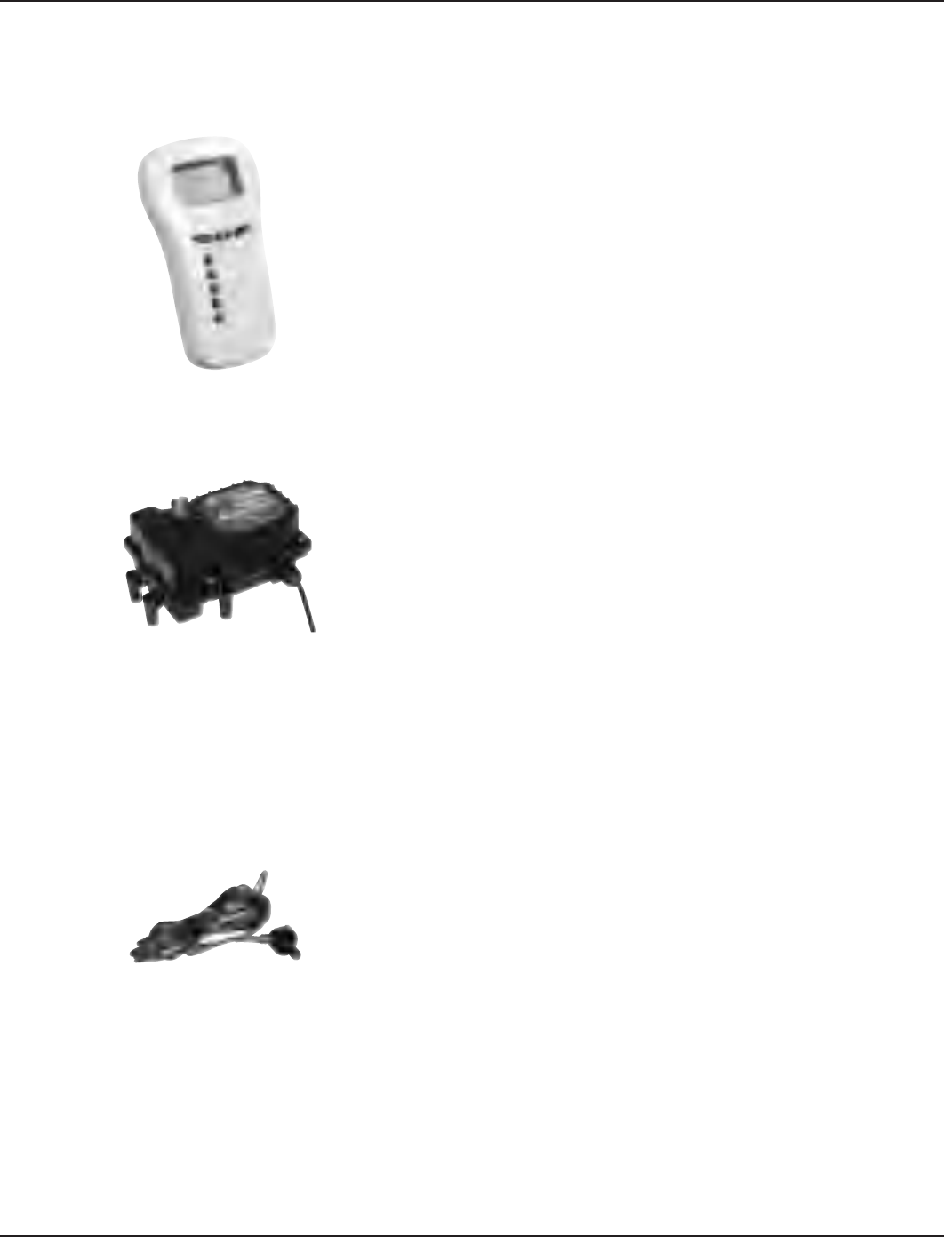
Hand-Held Controller (PE953)
The main function of the Hand-Held Controller is to transmit user
commands to the PE653 Receiving Device, PE650 Receiving Device, and/
or Z-Wave home control devices, and to display the status of the installed
equipment.
The unit floats if thrown in the pool or spa, is water-submersible, shock
resistant, and requires three (3) AA batteries. Expected battery life is about
one year in typical use.
When the components of a specific system are linked together into
a network, unique network ID codes supplied by the PE953 prevent
unauthorized use of the system by neighboring systems.
24-Volt Valve Actuator (PE24VA)
Designed with quality in mind, Intermatic’s 24-volt valve actuators
provide reliable control of 2-way and 3-way diverter valves for pool/
spa combinations and water features. The water flow can be altered
for specific applications through the adjustable cam, which rotates
diverter valves to multiple degree settings. The cam settings can be
easily adjusted by simply removing the lid. These valve actuators are
compatible with all pool/spa valves currently offered in the industry and
will retrofit into all pool/spa control systems.
24VAC Input Voltage•
Automates compatible diverter valves for •
pool/spa combos
Adjustable cam rotates diverter valves to •
multiple degree settings
Designed to operate most 2-way and 3-way diverter valves •
Shipping Weight - 3 lbs. (1.4 kg) •
Agency Approval - CSA/C-US•
Water Temperature Sensor (PA122)
The Intermatic Water Sensor (PA122) monitors both pool and spa water
temperature, depending on the position of the diverter valves. Installation is
necessary for the thermostatic control to work. The sensor can be ordered
separately.
ENTER
10 Multi-Wave PE653-PE953 Installation Guide
Copyright © 2010 Intermatic, Inc.
24-Volt Valve/Pump Switch (P4243ME)
Designed as part of the Multi-Wave system and for aftermarket and
retrofit applications, the P4243ME is most suited for controlling up to
two different circuits associated with pool/spa combinations, but can
also be used to control all the equipment typically needed in connection
with water features, water gardening, solar heating, and other similar
applications. This unit snaps into almost any Intermatic enclosure and
controls pumps up to 3HP, 24 volt supply for up to three valve actuators,
automated HIGH/LOW water temperature selector, heater connection
circuit, and push-button control for each load with indicator lights on the
face of the switch. In addition, the unit has connections for a hard-wired
or wireless remote and a master switch controller. For this installation, if an enclosure must be
added, we recommend Intermatic 2T2485GA.
120 or 208-240 input voltage•
Controls up to three valve actuators•
Controls two circuits•
Switches heater thermostat•
Remote control capabilities•
Shipping weight – 3 lb. (1.4 kg)•
Agency approval – CSA/C-US•
Contact Ratings — Each Circuit
17A Resistive, 120/240 VAC., 50/60 Hz•
1.5 HP @ 120 VAC., 50/60 Hz•
3.0 HP @ 240 VAC., 50/60 Hz•
10 Amp Tungsten, 120/240 VAC., 50/60 Hz•
Valve Actuator Supply: 24VAC 40VA•
Optional — Freeze (Air Temperature) Sensor (178PA28A)
Add the Intermatic Freeze or Air Temperature Sensor (178PA28A) to installations
where below-freezing outdoor temperatures are a concern.
Two: Plumbing and Wiring Examples 11
Providing a brighter solution.™
Section 2:
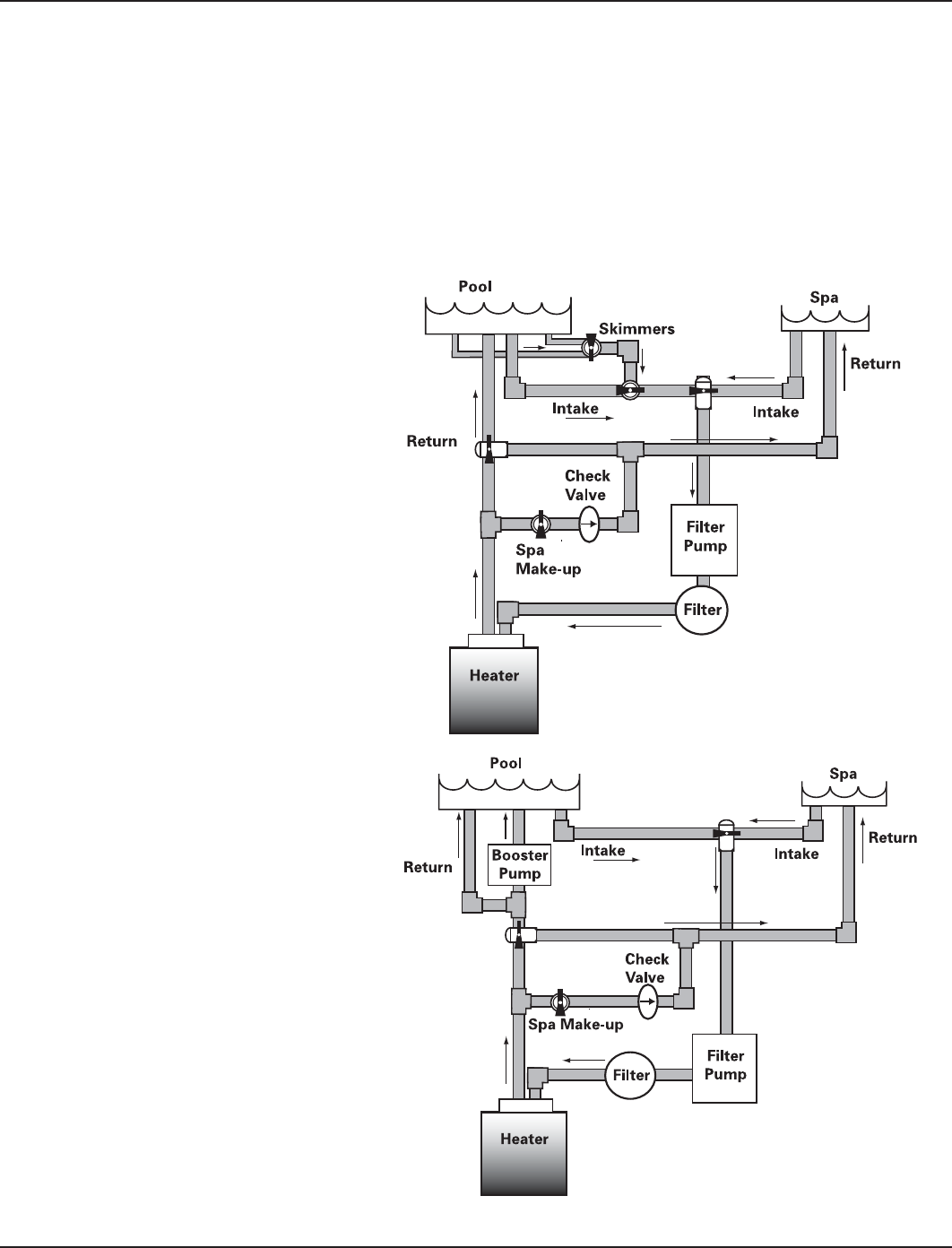
Plumbing Examples
The following diagrams show several plumbing and wiring examples of installations for pool and
spa that share a single filter pump, filter, and heater. If you are installing a pool only or spa only,
these diagrams will not apply.
For Pool and Spa
Combo Installations
For Booster Pump Pool
Cleaner Installations
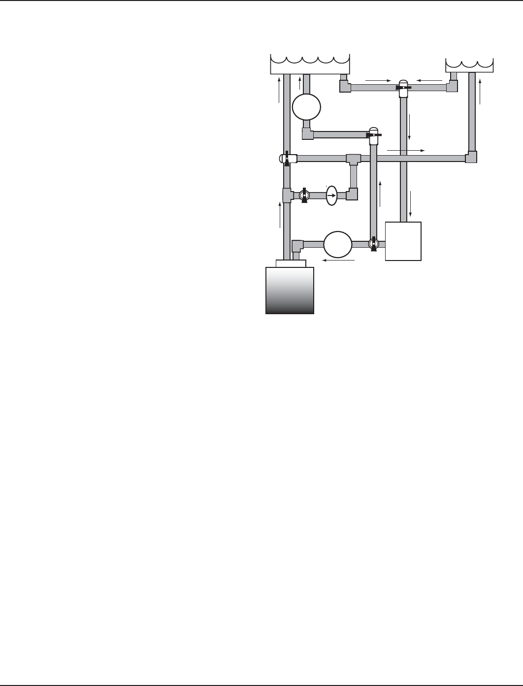
12 Multi-Wave PE653-PE953 Installation Guide
Copyright © 2010 Intermatic, Inc.
For Non-Booster Pump
Pool Cleaner Installations
Pool Spa
Filter
Check
Valve
Spa
Make-up
Filter
Pump
Intake
Return Return
Intake
Heater
Energy
Filter
Three: PE653 Receiving Device Installation 13
Providing a brighter solution.™
Section 3:
Installing and Wiring the PE653
Receiving Device
To avoid fire, shock, or death, turn off power at circuit breaker and test that power is off before wiring.•
Read instructions completely before installation and retain for future reference.•
Observe all national and local electrical and safety codes.•
Disconnect power when servicing or changing loads.•
Alterations or modifications to the device will void the warranty.•
For outdoor locations, rain-tight or wet location conduit hubs that comply with the requirements of UL 514B •
Conduit, Tubing, and Cable Fittings, must be used.
Ratings
Controller Power In:
120/240VAC, 50/60Hz - 5W MAX.•
Contact Ratings:
Load 1
120/240 VAC•
20A Resistive•
17 Full load A, 80 Lock Rotor A•
5A Tungsten or Ballast•
Loads 2-5
120/240 VAC•
15A Resistive•
10 Full load A, 60 Lock Rotor A•
5A Tungsten or Ballast•
•
Figure 3-1 (PE653 Receiving Device)
Include/Exclude Switch
120 / 240 VAC Selector Switch Circuit ON/OFF Switches
Fuse
(250 VAC - 0.1 A)
Threaded Conduit
Connection Bushing and Hub
Antenna Section
Load ON indicator
(Green LEDs)
Low Voltage Divider
(removable)
Low Voltage Knockout
AC Power
Conduit opening
Wiring Terminals
AC Power & Status
indicator (Red)
Antenna Section
Locking Screws
14 Multi-Wave PE653-PE953 Installation Guide
Copyright © 2010 Intermatic, Inc.
Wiring Instructions
Power Connections
1- Speed Pump: Must be powered from •
Terminal 3.
2-Speed Pump: Must be powered from •
Terminal 3 for High-Speed and Terminal 4 for
Low-Speed.
Booster Pump: Must be powered from •
Terminal 6.
Actuator Control: Must be powered from •
Terminal 7.
Heater Control: Must be Terminals 8 & 9. •
The metal enclosure must be ground bonded •
in compliance with national, state and local
codes.
Terminal 1 must always be Neutral when using
120 VAC power.
Terminal 1 must be L2 when using 240 VAC.
Terminal 2 must always be Hot or L1 for both
120 VAC and 240 VAC.
Terminal 3 must always be connected to the Hot
terminal of the pump.
Terminal 3 must always be connected to the
HIGH SPEED terminal of a 2-speed pump.
Terminal 4 must always be connected to the
LOW SPEED terminal of a 2-speed pump when
using a 2-speed motor.
Terminal 5 is the input supply for both terminals
6 & 7. This terminal is rated at 15 A. maximum.
Terminal 8 is the input supply for terminal 9.
The load is rated at 15 A. maximum.
Terminals 8 & 9 can be used for low voltage
provided the Low Voltage Divider is used to
separate the Low Voltage conductors from Line
Voltage conductors. Low voltage conductors
must exit the cabinet through a separate
opening. (See Figure 3-1)
Terminals 6 & 7 are function selectable with a
maximum combined rating of 15 A.
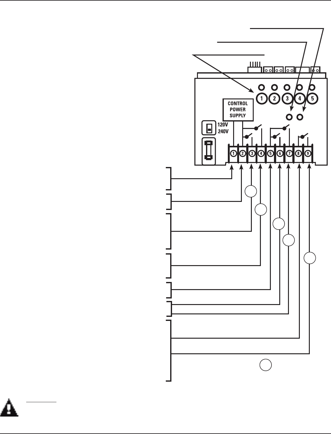
LOAD 1
LOAD 2
LOAD 3
LOAD 4
LOAD 5
POWER IN & CONTROL
POWER SUPPLY
POWER IN
POWER IN
1
1
2
3
4
5
= Circuit number
Figure 3-2 PE653 Master Control Center Power Terminal identification
CAUTION: The PE653 is a control device and NOT a safety disconnect. A proper sized fused disconnect
or breaker of no more than 125 Amp capacity must be provided in the power supply circuit. Proper
gauge wire should be based on local code requirements of amperage and wire length.
Manual ON/OFF Switches
AC POWER & STATUS indicator
INCLUDE/EXCLUDE switch
Three: PE653 Receiving Device Installation 15
Providing a brighter solution.™
Upper Terminal Connections
Installation Instructions
To avoid fire, shock, or death, turn off power at circuit breaker and test that power is off 1.
before wiring.
Select a location for the installation that is near the pool/spa equipment; at least five (5) feet 2.
distance or more from either the pool or spa and at least five (5) feet above ground level. The
PE653 must be mounted in a vertical (upright) position on the top of the enclosure.
Select the knockouts to be used. Remove the inner 1/2” knockout by inserting a flathead 3.
screw driver in the slot and carefully punch the knockout loose and remove the slug. If a
3/4’ knockout is required, remove the outer ring with pliers after removing the 1/2” knockout.
Smooth the edge with a file if required.
Place the metal enclosure in the desired mounting location and mark the three mounting 4.
holes. Install the top screw first and then hang the enclosure by the keyhole. Then install the
bottom screws, tightening all screws for a secure mounting.
Install electrical conduit as needed to comply with all national and local electrical and safety 5.
codes.
If a low voltage circuit or a heater control circuit is to be used, remove the low voltage 6.
knockout from the PE653 enclosure.
Install electrical conduit as required by national, state and local codes. 7.
Bond the enclosure in accordance with your state and local codes. Where required, 8.
connect a No. 8 AWG solid copper wire to the enclosure using Bonding Lug (part number
156T11047A). Connect the bonding wire to an approved earth ground.
Identify and install all wires necessary to complete the installation. Allow a length of 9.
approximately 18” of each wire at the metal enclosure for required connections of junctions.
Connect wiring for circuits as required. Refer to the diagrams in this section for wiring 10.
suggestions for specific equipment combinations. All splices and wire nut connections
should be in the metal enclosure, not in the PE653 enclosure.
Check and tighten all connections and circuits. 11.
Apply power.12.
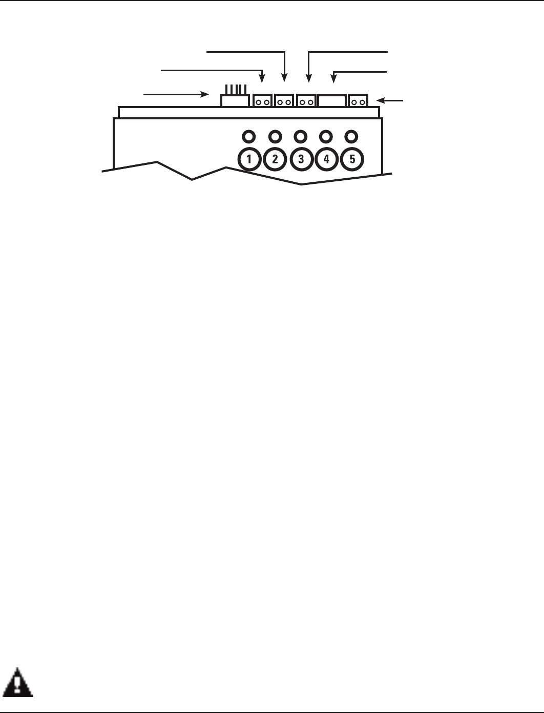
Figure 3-3 PE653 Master Control Center Upper Terminal identification
Local Antenna Connector
Air Sensor (178PA28A)
Water Sensor (PA122) Solar Sensor (PA122)
Remote Antenna Connector
Serial Connection (RS485)
NOTE: Observe polarity when
connecting pump manufacturer’s
cable to the Serial connection.
THE METAL ENCLOSURE MUST BE CLOSED AND SECURED WITH A LOCK OR TY-WRAP.

16 Multi-Wave PE653-PE953 Installation Guide
Copyright © 2010 Intermatic, Inc.
Variable-Speed Pumps
240V Variable-Speed Pump ......................................................................................................... Figure 3-4
One-Speed Pumps
120V 1-Speed Pump ................................................................................................................... Figure 3- 5
120V 1-Speed pump + any 4 120 VAC auxiliary equipment ........................................................ Figure 3- 6
120V 1-Speed pump + 120V Blower or Lights + 120V Booster Pump + 120V Actuator + Heater Figure 3-7
120V 1-Speed pump + 120V Lights + 120V Blower + 120V Actuator + Heater ........................... Figure 3-8
240V 1-Speed Pump ................................................................................................................... Figure 3-9
240V 1-Speed pump + any 4 240 VAC auxiliary equipment ........................................................ Figure 3-10
240V 1-Speed pump + 240V Blower + 240V Booster Pump + 240V Actuator + Heater ............... Figure 3-11
240V 1-Speed pump + 120V Lights + 120V Blower + 240V Actuator + Heater ........................... Figure 3-12
Two-Speed Pumps
240V 2-Speed Pump ................................................................................................................... Figure 3-13
240V 2-Speed pump + any 3 240 VAC auxiliary equipment ........................................................ Figure 3-14
240V 2-Speed pump + any 3 120 VAC auxiliary equipment ........................................................ Figure 3-15
240V 2-Speed pump + 240V Booster Pump + 240V Actuator + Heater ....................................... Figure 3-16
240V 2-Speed pump + 120V Lights + 240V Blower + Heater ...................................................... Figure 3-17
240V 2-Speed pump + 240V Blower + 240V Actuator + Heater .................................................. Figure 3-18
240V 2-Speed pump + 240V Booster pump + 240V Blower + Heater ......................................... Figure 3-19
240V 2-Speed pump + 240V Booster pump + 120V Light + Heater ............................................. Figure 3-20
240V 2-Speed pump + 240V Booster pump + other 120 VAC equipment + Heater ..................... Figure 3-21
List of Wiring Diagrams
Three: PE653 Receiving Device Installation 17
Providing a brighter solution.™
Variable-Speed Pumps
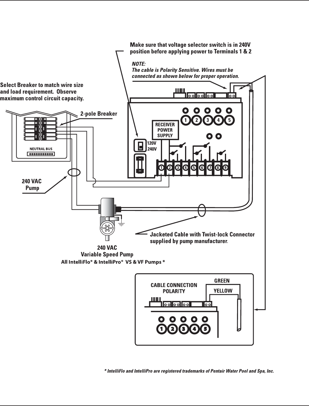
240V Variable-Speed Pump
Figure 3-4
18 Multi-Wave PE653-PE953 Installation Guide
Copyright © 2010 Intermatic, Inc.
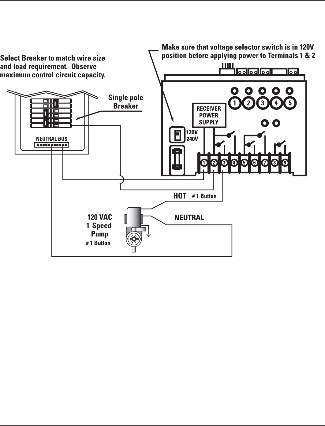
1-Speed Pumps
120V 1-speed pump
Figure 3-5
Three: PE653 Receiving Device Installation 19
Providing a brighter solution.™
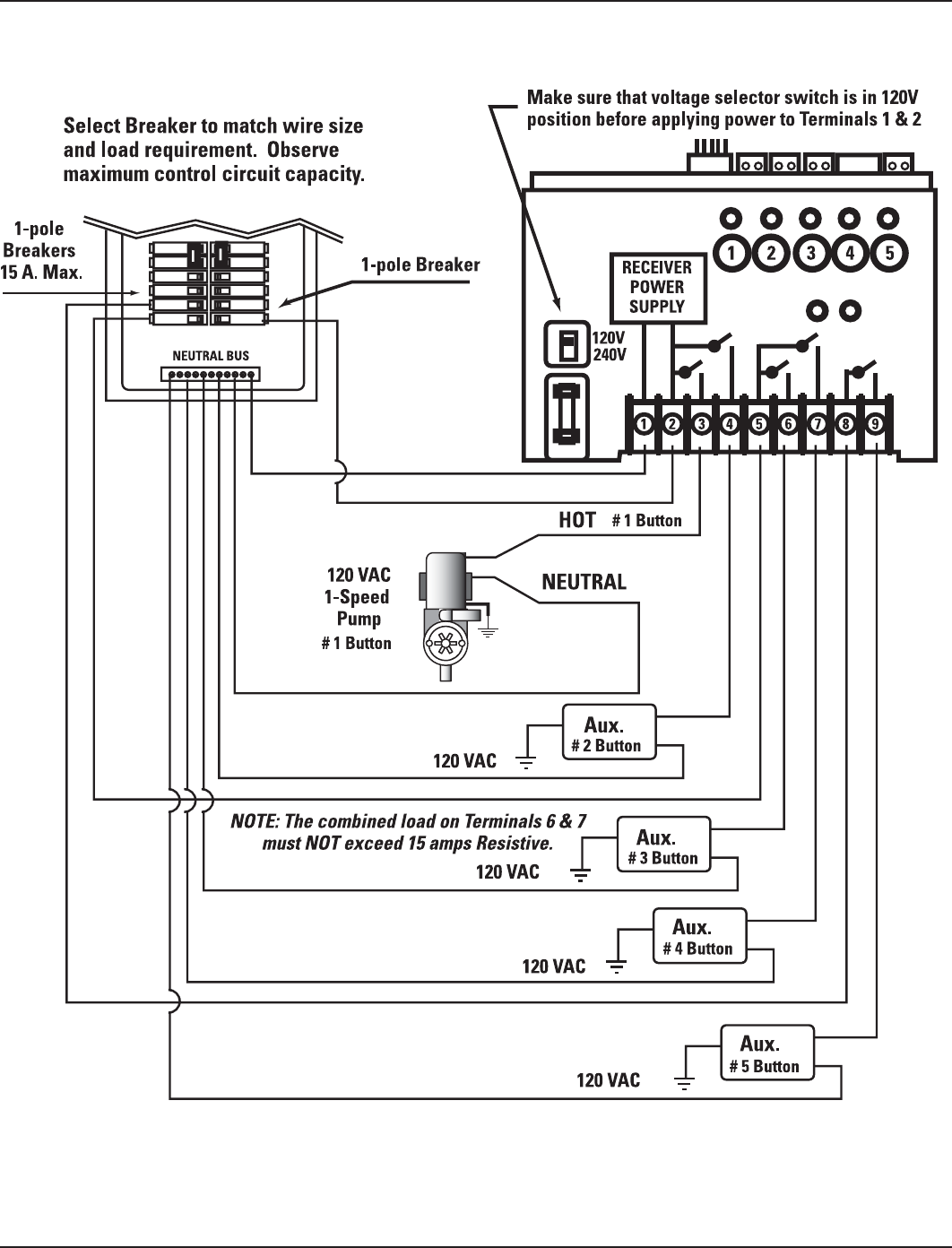
120V 1-speed pump + any four 120 VAC auxiliary equipment
Figure 3-6
20 Multi-Wave PE653-PE953 Installation Guide
Copyright © 2010 Intermatic, Inc.
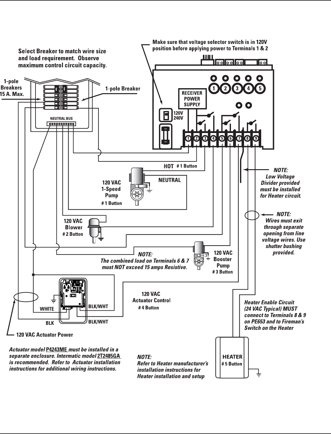
120V 1-speed pump + 120 VAC blower or lights + 120V booster
pump + 120V actuator + heater
Figure 3-7
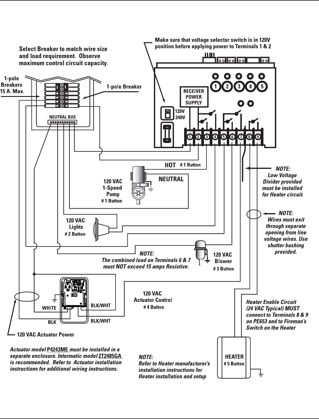
Three: PE653 Receiving Device Installation 21
Providing a brighter solution.™
120V 1-speed pump + 120V blower + 120V lights + 120V actuator +
heater
Figure 3-8
22 Multi-Wave PE653-PE953 Installation Guide
Copyright © 2010 Intermatic, Inc.
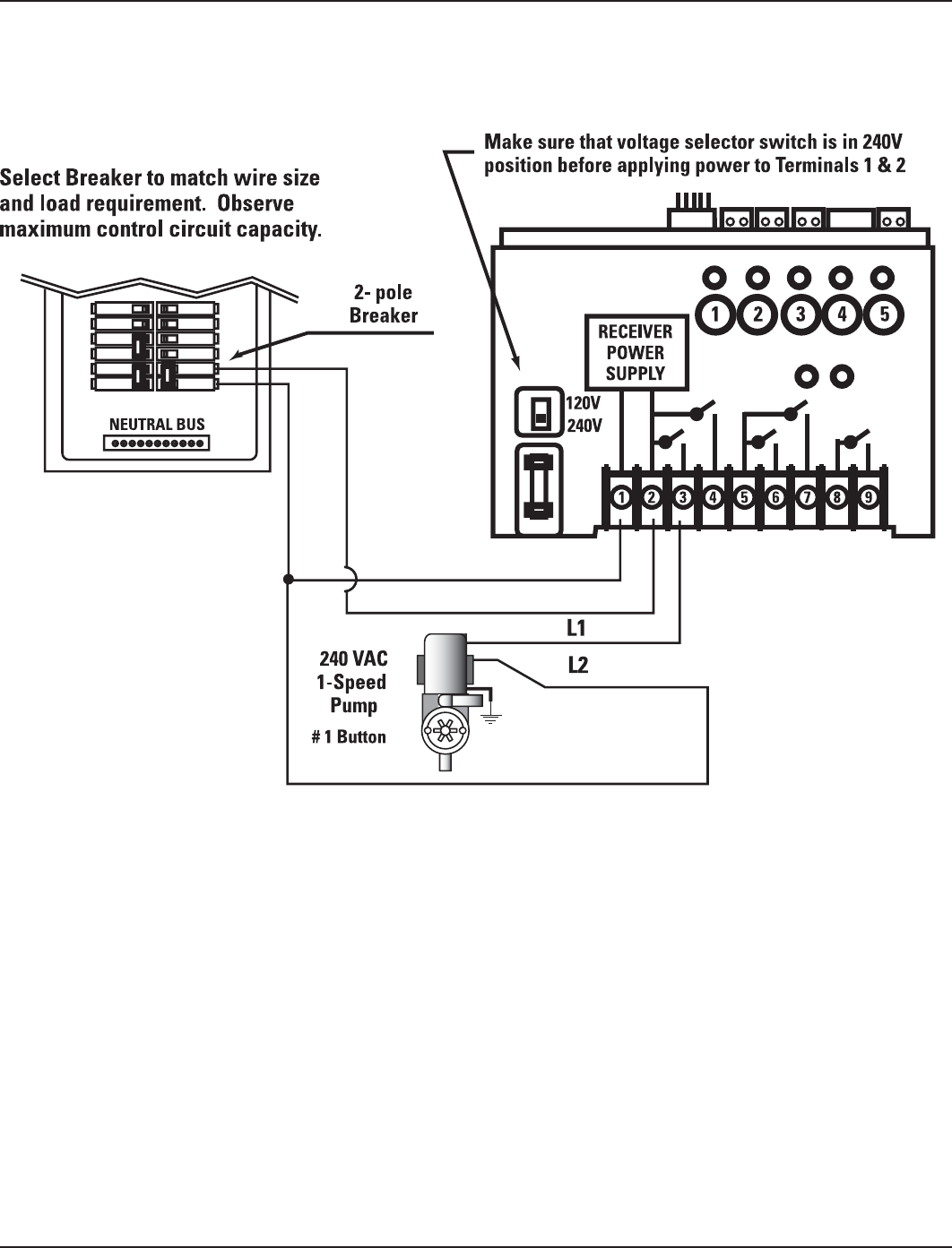
240V Pumps
240V 1-speed pump
Figure 3-9
Three: PE653 Receiving Device Installation 23
Providing a brighter solution.™
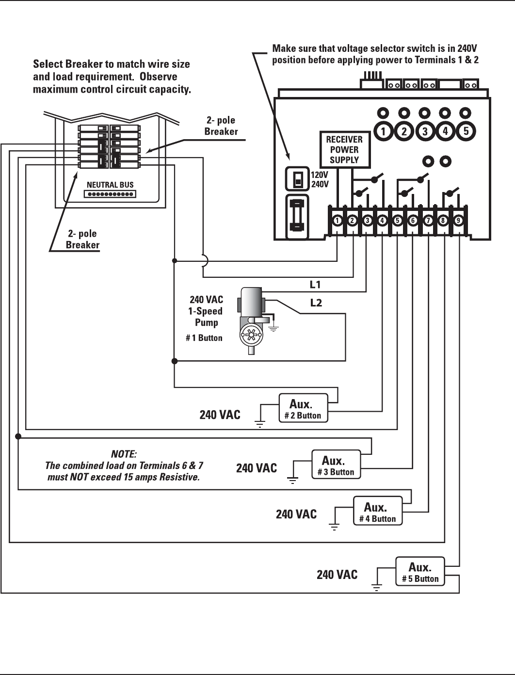
240V 1-speed pump + any four 240 VAC auxiliary equipment
Figure 3-10
24 Multi-Wave PE653-PE953 Installation Guide
Copyright © 2010 Intermatic, Inc.
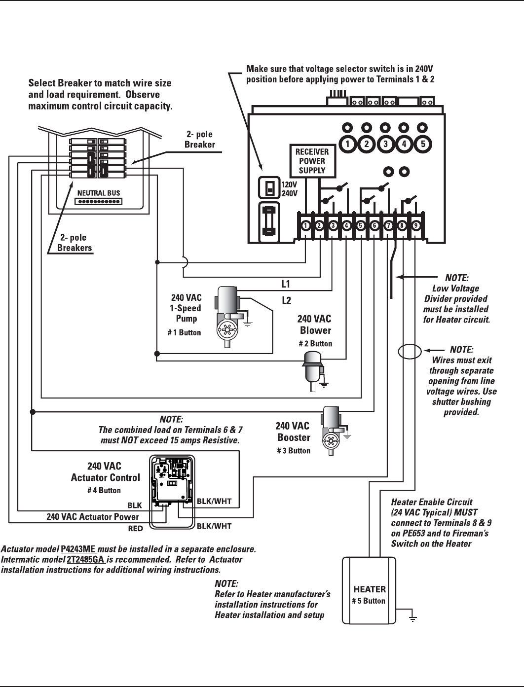
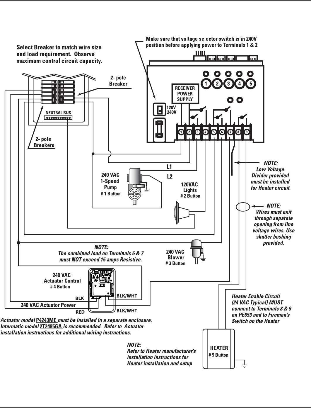
240V 1-speed pump + 240V blower + 240V booster pump + 240V
actuator + heater
Figure 3-11
Three: PE653 Receiving Device Installation 25
Providing a brighter solution.™
240V 1-speed pump + 120V lights + 120V blower + 240V actuator +
heater
Figure 3-12
26 Multi-Wave PE653-PE953 Installation Guide
Copyright © 2010 Intermatic, Inc.
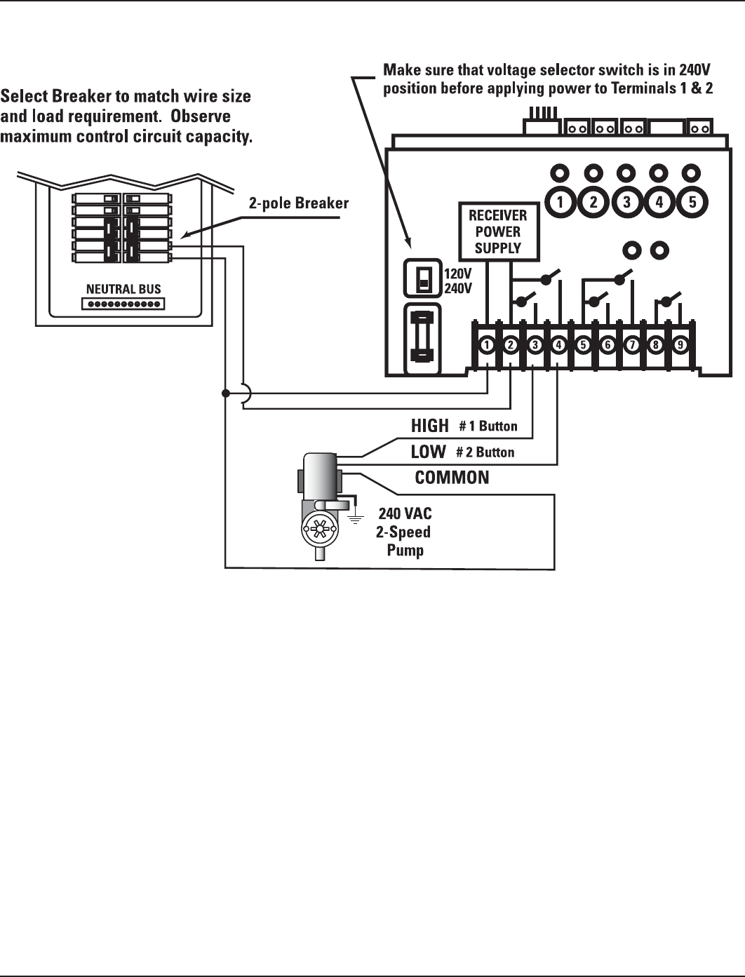
240V 2-Speed Pump
Figure 3-13
Three: PE653 Receiving Device Installation 27
Providing a brighter solution.™
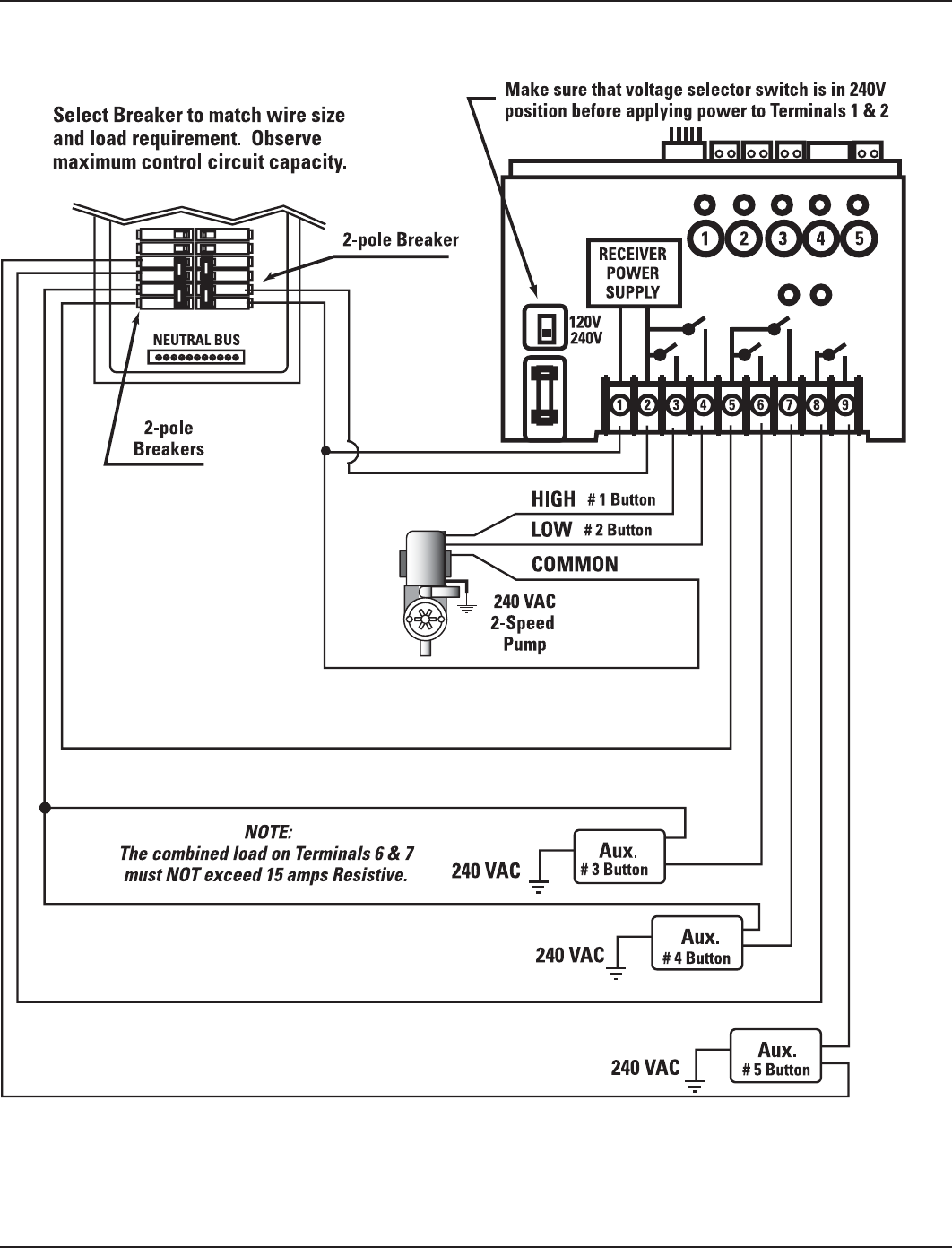
240V 2-speed pump + any three 240VAC auxiliary equipment
Figure 3-14
28 Multi-Wave PE653-PE953 Installation Guide
Copyright © 2010 Intermatic, Inc.
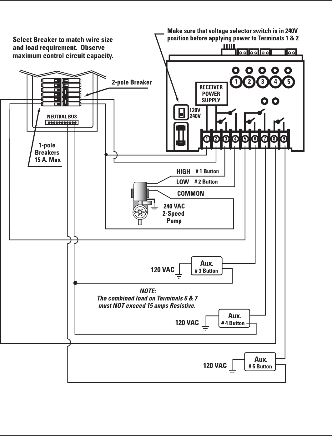
240V 2-Speed pump + any 3 120 VAC auxiliary equipment
Figure 3-15