Intermec Technologies 2126 PCMCIA Wireless Network Interface User Manual ttlepage
Intermec Technologies Corporation PCMCIA Wireless Network Interface ttlepage
Contents
- 1. APPENDIX M
- 2. APPENDIX N
APPENDIX M
578-100-019 Revision B Page 1 of 4
Compliance Statement Insert
Device Name: Wireless LAN Access Point Model Number: 6710
The responsible party for the compliance of this device is: Intermec Technologies Corporation
550 Second Street SE
Cedar Rapids, Iowa 52401 USA
(319) 369-3100
CAUTION: See users guide instructions for handling, charging, and replacing batteries. Failure to follow those instructions can result in
personal injury, fire, or battery explosion.
This product conforms to the following approvals. The user(s) of this product are cautioned to use accessories and peripherals approved by
Norand Corporation. The use of accessories other than those recommended or changes to this product that are not approved by Norand
Corporation may void the compliance of this product and may result in the loss of the users authority to operate the equipment.
FCC Digital Emissions Compliance
This equipment has been tested and found to comply with the limits for a Class B digital device, pursuant to Part 15 of the FCC Rules. These limits are
designed to provide reasonable protection against harmful interference in a residential installation. This equipment generates, uses and can radiate radio
frequency energy and, if not installed and used in accordance with the instructions, may cause harmful interference to radio communications. However, there is
no guarantee that interference will not occur in a particular installation. If this equipment does cause harmful interference to radio or television reception,
which can be determined by turning the equipment off and on, the user is encouraged to try to correct the interference by one or more of the following measures:
• • Reorient or relocate the radio of television receiving antenna.
• • Increase the separation between the computer equipment and receiver.
• • Connect the equipment into an outlet on a circuit different from that to which the radio or television receiver is connected.
• • Consult the dealer or an experienced radio television technician for help.
Canadian Digital Apparatus Compliance
This Class B digital apparatus meets all requirements of the Canadian Interference-Causing Equipment Regulations.
Cet appareil numérique de la classe B respecte toutes les exigences du Règlement sur le matériel brouilleur du Canada.
FCC Spread Spectrum Transmitter Compliance
This device is also certified to operate under Part 15, Subpart C, Section 15.247 of the FCC rules for Intentional Radiation Products. This certification
includes Docket 87-389 covering rules effective June 1994. It may not cause interference to authorized radio communication devices, and must accept any
interference caused by those devices.
Canadian RSS-210 Spread Spectrum Transmitter Compliance
Operation is subject to the following two conditions: (1) this device may not cause interference, and (2) this device must accept any interference, including
interference that may cause undesired operation of the device.
Canadian 2.4 GHz Spread Spectrum Radio Certification
This device requires a radio license, unless it is installed totally inside a building. (User’s must obtain this license.)
Une license radio est requise oour ces dispositifs, sauf ouor ceux installés tout á fait á l’intérieur d’un bâtiment. (Il faut que l’utilisateur obtienne cette
license.)
Antenna Requirements
FCC rules section 15.203 and Canada RSS-210 require that this device be operated using an antenna furnished by Norand Corporation. The antenna
coupling on this product has been designed to accept only antennas manufactured Norand. Use of an antenna other than that furnished with the equipment is
prohibited by FCC and Industry Canada rules.
European Notice
The 902-928 MHz Spread Spectrum Transmission (SST) radio referred to within the manual is not available for sale in Europe (including, but not limited to,
Great Britain, Italy, Germany, France, Spain, Norway, Denmark, Sweden, Finland, Portugal, and the Benelux countries). Any references in the manual to 902-
928 MHz SST, or modules containing 902-928 MHz SST radios, should be disregarded by the users of this product in Europe.

578-100-019 Revision B Page 2 of 4
DECLARATION OF CONFORMITY
(According to ISO/IEC Guide 22 and EN 45014)
PAGE ONE OF TWO
THE PRODUCT HEREWITH COMPLIES WITH THE REQUIREMENTS OF :
THE LOW-VOLTAGE DIRECTIVE 72/32/EEC.
THE EMC DIRECTIVE 89/336/EEC.
Manufacturer’s Name: European Representative:
Intermec Technologies Corporation Intermec International Incorporated
550 2nd Street SE Sovereign House, Vastern Road
Cedar Rapids, Iowa 52401 Reading, Berkshire
RG1 8BT England
Declares that the product listed below:
Product Type: ITE/Residential, Commercial, and Light Industrial
Product Name: Wireless LAN Access Point Model Number: 6710
Product Options: All Beginning Serial Number: All
Date Issued: May 30, 1996
Conforms to the following product specifications:
Safety: IEC 950 / EN 60950
EMC: EN 55022 : 1995 / CISPR Publications 22 : 1993, Class B Limits and Methods
EN 50082-1 : 1992 Generic Immunity Standard
ETS 300 339 : Jun. 1993 Draft RES Generic EMC for radio equipments
IEC 801-2 per Draft prETS 300 339, Clause 9.2
+ 8 kV Air / + 4 kV Contact
IEC 801-3 per Draft prETS 300 339, Clause 9.1
3 V/M, 80-1000 MHz, 80% @ 400 Hz
IEC 801-4 per Draft prETS 300 339, Clause 9.3
AC Power Leads + 2 kV; Signal and Control Leads + 1.0 kV
IEC 801-5 (Draft) Tested per Draft prETS 300 339, Clause 9.8
IEC 801-6 Tested per Draft prETS 300-339, Clause 9.4 AC Power Leads and Signal and
Control Leads 3 Vrms, 150 kHz - 80 MHz, 80% @ 400 Hz
Draft prETS 300 339, Clause 9.6, Tested per IEC 1000-4-11 30%
(10 ms), 60% (100 ms), and 95% (5000ms) of 220 VAC nominal.
prETS 300 683 : EMC Standard for short range devices
IEC1000-4-2 Tested per Draft prETS 300 683, Clause 9.3
+ 8 KV Air / + 4 KV Contact
ENV 50140 Tested per Draft prETS 300 683, Clause 9.2
3 V/M, 80-1000 MHz, 80% @ 400 Hz
IEC1000-4-4 Tested per Draft prETS 300 683, Clause 9.4
AC Power Leads + 2 kV; Signal And Control Leads + 1.0 kV
ENV 50142 Tested per Draft prETS 300 683, Clause 9.8
ENV 50141 Tested per Draft prETS 300 683, Clause 9.5
AC Power Leads and Signal and Control Leads 3 Vrms,
150 kHz - 80 MHz, 80% @400 Hz
IEC 1000-4-11 Tested per Draft prETS 300 683, Clause 9.7
30% (10ms), 60% (100ms), and 95% (5000ms) of 230 VAC nominal.
Type Approval Certification(s): see second page of Declaration of Conformity

578-100-019 Revision B Page 3 of 4
DECLARATION OF CONFORMITY
PAGE TWO OF TWO
I, the undersigned, hereby declare that the equipment specified above conforms the above Directive(s) and
Standard(s).
Company Official: Arvin Danielson Position: Vice President
Signature: Signed Copy on File Date: June 3, 1998
European Contact: Scott Mercer, Intermec International Incorporated, Sovereign House, Vasern Road, Reading,
Berkshire, RG1 8BT England; Phone INT+44 118 987 9400; Fax INT+44 118 987 9401
Product Type: ITE/Residential, Commercial, and Light Industrial
Product Name: Wireless LAN Access Point Model Number: 6710
Product Option: RM111
Type Approval Certifications:
BRAZIL: FCC ID: EHARM450P CANADA: 1008 195 234A
CHILE: FCC ID: EHARM450P COLOMBIA: FCC ID: EHARM450P
COSTA RICA: FCC ID: EHARM450P DENMARK: 97001D
Telestyrelsen
FINLAND: Label added in Finland GERMANY: A129416H RM11
A132600J QE
HONG KONG: FCC ID: EHARM450P ICELAND: Samþykkisnúmer IS-2454-00
ITALY: DGPGF/SEGR/2/144/03/336451/AP/0000778 NORWAY: Typegodkjenningsnummer
NO97000460-R
PERU: FCC ID: EHARM450P SPAIN: E D.G.Tel 07 97 0100
SWEDEN: Godkand av Post&Telestyrelsen UNITED ARAB No special markings
Ue970071 EMIRATES:
UNITED W.T. License Exempt URUGUAY: FCC ID: EHARM450P
KINGDOM: ID: 11918 I-ETS 300 220
VENEZUELA: FCC ID: EHARM450P
Product Option: RM160
Type Approval Certifications:
ARGENTINA: FCC ID: EHARM915P AUSTRALIA: FCC ID: EHARM915P
BRAZIL: FCC ID: EHARM915P CANADA: 1008 102 269
CHILE: FCC ID: EHARM915P COLOMBIA: FCC ID: EHARM915P
COSTA RICA: FCC ID: EHARM915P MEXICO: SCýT: RCPNORM97-319
PERU: FCC ID: EHARM915P PHILIPPINES: FCC ID: EHARM915P
UNITED STATES: FCC ID: EHARM915P VENEZUELA: FCC ID: EHARM915P
Product Option: RM180
Type Approval Certifications:
ARGENTINA: FCC ID: EHARM24002PC AUSTRALIA: FCC ID: EHARM24002PC
AUSTRIA: CEPT-RLAN A BRAZIL: FCC ID: EHARM24002PC
CANADA: 1008 101 760A CHILE: FCC ID: EHARM24002PC
COLOMBIA: FCC ID: EHARM24002PC COSTA RICA: FCC ID: EHARM24002PC
DENMARK: CEPT/RLAN/DK/9514 FINLAND: Label added in Finland
Telestyrelsen
FRANCE: 96 0145 PP 0 GERMANY: G128682H

578-100-019 Revision B Page 4 of 4
GREECE: ÁÑ×ÉÊÁ ÅËÅÃ×ÏÌÅÍÇ ÓÕÓÊÅÕÇ HONG KONG: FCC ID: EHARM24002PC
×ÑÇÓÇ:ÌÅÔÁÖÏÑÁÓ ÄÅÄÏÌÅÍÙÍ
'Åãêñéóç Êõêëïöñéáò ÕÐÌÅ/ÄÔÅÅ/ÅÊ537
ICELAND; CEPT RLAN IS-2433-01 INDIA: FCC ID: EHARM24002PC
ITALY: CEPT-RLAN I KOREA: Radio Type Registration
DCSR/2/4/144-03/335321/AT/0000158
MEXICO: SCýT: RCPNORM97-308 NETHERLANDS: ministrie van verkeer en waterstaat
NL96030574 CEPT-RLAN NL
NORWAY: CEPT-RLAN N PERU: FCC ID: EHARM24002PC
POLAND: M£ SINGAPORE: TAC No: PMREQ-WLAN-B-1028-96
Œ.H. Nr 042/98
SPAIN: CEPT RLAN E 00 96 0431 SWEDEN: Godkaend av Post- och Telestyrelsen
Ue 960004
CEPT-RLAN S Norand Corporation RM180
TAIWAN: 85G0069 TURKEY: FCC ID: EHARM24002PC
UNITED CEPT-RLAN GB UNITED STATES: FCC ID: EHARM24002PC
KINGDOM:
VENEZUELA: FCC ID: EHARM24002PC
Product Option: RM188
Type Approval Certifications:
JAPAN: MKK Approved

6710 Access Point
USER’SGUIDE
""""""""""""""""""""""""""""
P/N961-047-081
RevisionC
July1998

"NOTICEThispublicationcontainsinformationproprietarytoIntermecTechnologiesCorpo-
ration.Itisbeingsuppliedtoyouwiththe express understandingthat theinfor-
mationcontainedhereinisforthebenefitofthecontractingpartyonly,andmay
notbecopied,distributed,ordisplayedtothird partieswithout the express writ-
tenconsentofIntermecTechnologiesCorporation,andshall bereturnedtoInter-
mecTechnologiesCorporation uponwrittenrequest.Ifapurchase,license,or
nondisclosureagreementhasbeenexecuted,thetermsofthatagreementshall
governthisdocument.
Thispublicationisfurnishedforinformationonly,andtheinformationinitis
subject tochangewithoutnotice.Althougheveryefforthasbeenmadetoprovide
completeandaccurateinformation,IntermecTechnologiesCorporationassumes
noresponsibilityorliabilityforanyerrorsorinaccuraciesthatmayappearinthis
document.
Wewelcomeyour commentsconcerningthispublication.Althougheveryeffort
hasbeenmadetokeepitfree oferrors,somemayoccur.Whenreportingaspecific
problem,pleasedescribeitbrieflyandincludethebooktitleand partnumber,as
well astheparagraphorfigurenumberandthepagenumber.
Sendyour commentsto:
IntermecTechnologiesCorporation
PublicationsDepartment
550 SecondStreetSE
CedarRapids,IA52401
INTERMEC,NORAND,PEN*KEY,andTRAKKER areregisteredtrademarks
andANTARESandJANUSaretrademarksofIntermecTechnologiesCorporation.
Ó1996 IntermecTechnologiesCorporation.All rightsreserved.
Thispublicationprintedonrecycled paper.
Acknowledgments
Portionsofthisproductcontainsoftwarewhichislicensedfromandiscopyrighted
byEpilogueTechnology Corporation,1988--1995,all rightsreserved.
DECnetandVTareregisteredtrademarksofDigitalEquipmentCorporation.
EthernetisatrademarkofXeroxCorporation.
Hewlett-PackardandHPareregisteredtrademarksandHPOpenViewisa
trademarkofHewlett-PackardCompany.
MicrosoftisaregisteredtrademarkofMicrosoftCorporation.
NetscapeNavigatorisatrademarkofNetscapeCommunicationsCorporation.
Novell andNetWare areregisteredtrademarksandIPXandSPXaretrademarks
ofNovell,Inc.
PCATisaregisteredtrademarkofInternationalBusiness MachinesCorporation.
PROCOMM andPROCOMM PLUSareregisteredtrademarksofDataStorm
Technologies,Inc.
ProximandRangeLANaretrademarksofProxim,Inc.
FCC ComputerCompliance
"NOTICEThisequipmentmeetsClass BdigitaldevicelimitsperPart15 ofFCC Rules.
Theselimitsprotectagainstinterferenceinaresidentialarea.Itemits,uses,and
canradiateradiofrequencyenergy.Ifyoudonotinstall andusethe equipment
accordingtoitsinstructions,itmayinterferewithradiosignals.However,thereis
noguarantee thatinterferencewill notoccurinaparticularinstallation.
Ifthisequipmentdoescauseharmful interferencetoradio ortelevisionreception,
whichcanbedeterminedbyturningourequipmentoff andon,theuserisencour-
agedtotrytocorrect theinterferencebyone ormore ofthefollowingmeasures:
"Reorientor relocatetheradio ortelevisionreceivingantenna.
"Increasetheseparationbetweenthecomputerequipmentandreceiver.
"Connect the equipmentintoanoutletonacircuitdifferentfromthat to
whichtheradio ortelevisionreceiverisconnected.
"Consult thedealeroranexperiencedradio ortelevisiontechnicianfor
help.
FCC SpreadSpectrumRadioCertification
"NOTICEThisdeviceiscertifiedto operateunderPart15,SubpartC,Section15.247 ofthe
FCC rulesforIntentionalRadiationProducts.ThiscertificationincludesDocket
87-389 coveringruleseffectiveJune1994.Itmaynotcauseinterferenceto
authorizedradiocommunicationdevices,andmustacceptanyinterferencecaused
bythosedevices.
AntennaRequirements
"NOTICEFCC rules section15.203 andCanada’sRSS-210 requirethat thisdevicebe oper-
atedusinganantennafurnishedbyIntermecTechnologiesCorporation.Thean-
tennacouplingonthisproducthasbeendesignedtoacceptonlyantennas
manufacturedbyus.Use ofanantennaotherthanthatfurnishedwiththe equip-
mentisprohibitedbyFCC andIndustryCanadarules.
CanadianComputerCompliance
ThisClass Bdigitalapparatusmeetsall requirementsoftheCanadian
Interference-CausingEquipmentRegulations.
Cetappareil numeriquedelaclasseBrespectetouteslesexigencesduReglement
surlematerialboilleurduCanada.
CanadianSpreadSpectrumRadioCertification
"NOTICEThisdevicecomplieswithRSS-210 ofIndustryCanada.Operationis subject to
thefollowingtwoconditions:(1)thisdevicemaynotcauseinterference,and(2)
thisdevicemustacceptanyinterference,includinginterferencethatmaycause
undesiredoperationofthedevice.
Canadian2.4GHzRadio License
"NOTICEThisdevicerequiresaradiolicense,unless itisinstalledtotallyinsidea building.
(Usersmustobtainthislicense)
Unelicenceradio estrequisepour cesdispositifs,saufpour ceuxinstalléstoutà
faitàl’intérieurd’un bâtiment.(Ilfautquel’utilisateurobtiennecettelicence.)
TelephoneInstallation Warning Notices
Thefollowingnoticesapplyto equipment thatmaybeconnectedtotelephonelines
orsystems.Foryourpersonalsafety,andtoprotect thisequipmentfrompotential
electricalorphysicaldamage,doNOTconnectequipment totelephonelinesor
datacommunicationequipmentunless thefollowingwarningshavebeenread,
understood,andcompliedwith.
"Neverinstall telephonewiringduringalightningstorm.
"Neverinstall telephonejacksinwetlocationsunless thejackis specifi-
callydesignedforwetlocations.
"Nevertouch uninsulatedtelephonewiresorterminalsunless thetele-
phonelinehasbeendisconnectedat thenetworkinterface.
"Usecautionwheninstallingormodifyingtelephonelines.
"Avoidusingtelephone(otherthancordless type)duringanelectrical
storm.Theremaybearemoteriskofelectricshockfromlightning.
"Donotusethetelephonetoreportagasleakinthevicinityoftheleak.
Installation du téléphone:avertissements
Lesavertissementsquisuivents’appliquentàtoutéquipementquipeutêtre
branchéauxlignesousystèmestéléphoniques.Pourvotresécuritépersonnelle et
pourprotégerl’équipementdetoutdommage électrique ouphysiquepotentiel,NE
PASbrancherun ordinateurtablette électronique ousespériphériquesauxlignes
téléphoniquesouéquipementsavantquelesavertissements suivantsaientétélus,
comprisetobservés:
"Nejamaisinstallerdecâblagetéléphoniquependantun orage électrique.
"Nejamaisinstallerdeprisetéléphoniquedansun endroithumideà
moinsquelapriseaitétéspécifiquementconçuepourêtreutilisée dans
lesendroitshumides.
"Nejamaistoucherlesfilsdetéléphone oudel’équipement terminalnon
isolésàmoinsquelalignetéléphoniquen’aitétédébranchée del’inter-
faceréseau.
"Userdeprudencelorsdel’installationoudelamodificationdelignes
téléphoniques.
"Éviterd’utiliserun téléphone(autrequ’un appareil téléphoniquesans
fil)pendantun orage électrique.Ilpourraityavoirun faiblerisqued’é-
lectrocutionparlafoudre.
"Nepasutiliserletéléphoneafindesignalerunefuitedegazàproximité
delafuite.
BCAUTION:Intermec Technologies Corporation suggests you buy cables fromus
toconnectwith otherdevices.Ourcables are safe,meetFCC rules,
and suitourproducts.Othercables may notbetested.They may
cause problemsfromelectrostaticdischargeorinducedenergy.Our
warranties do notcoverloss, injury,ordamagefromothercables.

6710 Access PointUser’sGuide i
CONTENTS
""""""""""""""""""""""""""""
SECTION1
Preface 1-1.............................................
Purpose ofThisGuide1-1................................
Organization1-1........................................
IntendedAudience1-3...................................
RelatedPublications1-3.................................
Wireless StationUser’sGuides1-3....................
SystemManagementPublications1-4.................
CustomerSupport1-4...................................
SECTION2
Features and Functional Overview2-1....................
Description2-1.........................................
BridgingFunctionality2-2...............................
GeneralConcepts2-2................................
Access PointBridgingLayer2-4......................
NetworkOrganization2-4........................
Forwarding2-5..................................
PendingMessages2-5............................
FloodingConfigurations2-6.......................
Proxy ARPServer2-7............................
BridgePorts2-7.....................................
EthernetPort2-7................................
EthernetPortFilters2-8.........................
RadioPorts2-9..................................
OWL/IP Port2-10.................................

CONTENTS"
ii 6710 Access PointUser’sGuide
ConfigurationandManagement2-11......................
Configuration2-11....................................
DiagnosticsandConfigurationPort2-11............
RemoteAccess 2-12...............................
TCP/IP2-12...................................
DHCPClient2-12.............................
Telnet2-12....................................
HTTP 2-13....................................
ElectronicSoftwareDistribution2-13...............
TFTP ClientandServer2-13...................
Scripting2-13.................................
NetworkManagement2-14............................
SampleConfiguration2-14................................
Components2-16.........................................
Accessories2-19..........................................
PowerCord2-19......................................
IndustrialLockingMountingBracket2-19..............
SECTION3
Installation 3-1..........................................
CheckingtheDefaultConfiguration3-1...................
PreparingfortheInstallation3-2.........................
CollectingtheEquipment3-2............................
EthernetLANComponents3-2.......................
10BASE2Components3-3........................
10BASE-TComponent3-3........................
10BASE5Components3-4........................
CommunicationEquipment3-5.......................
LocalDIAGPortAccess 3-5.......................
Telnet3-6.......................................
WebBrowser3-6.................................
NetworkManagementPlatform3-6...................
FindingtheBestLocation3-7............................
SiteSurvey3-7......................................
GeneralInstallationGuidelines3-7...................
MountingtheAccess Point3-8...........................
Horizontal(Tabletop)Mount3-8......................
VerticalandCeilingMounts3-9.......................

CONTENTS"
6710 Access PointUser’sGuide iii
ConnectingtoEthernet3-10..............................
10BASE2Ethernet3-11...............................
EndofSegment3-11..............................
Middle ofSegment3-12............................
10BASE5Ethernet3-13...............................
N-SeriesTransceiver3-13..........................
VampireTap3-13.................................
10BASE-TEthernet3-16..............................
InstallingPC Cards3-17..................................
WLIF3-17...........................................
900 MHz3-18........................................
S-UHF3-19..........................................
ApplyingPower3-20.....................................
SECTION4
Configuration 4-1.......................................
CreatingaLocalDIAGPortSession4-2...................
AccessingtheConfigurationMenus4-4................
AccessingtheROMCommandMonitor4-5.............
CreatingaTelnetSession4-6.............................
DefaultandSiteSettings4-7.............................
TCP/IP4-7..........................................
Security4-8.........................................
Bridge4-8..........................................
ConfiguringtheAccess Point4-12.........................
MainMenu 4-12......................................
UsingtheViewCommand4-14........................
TCP/IPOptions4-16......................................
IPAddress 4-16......................................
IPSubnetMask4-17..................................
IPRouter4-18........................................
IP FrameType4-19...................................
DHCP4-19...........................................
DHCPServerName4-20..............................
BootpOperation4-21..............................
NetworksWithDHCPandBootpServers4-21.......
Handshaking4-21................................
InfiniteLeases4-21...............................
AutoARPMinutes4-22...............................

CONTENTS"
iv6710 Access PointUser’sGuide
BridgeOptions4-23......................................
Serial Number4-23...................................
LanID4-23..........................................
[Root]4-24...........................................
RootPriority4-24.................................
SuperRootCandidates4-24....................
SuperRootSelection4-25......................
SuperRootRedundancy4-25...................
[GlobalRadio]4-25................................
SetGlobally4-27..............................
Value4-27....................................
[GlobalFlooding]4-28.............................
Inbound4-28..................................
OutboundtoSecondaries4-29..................
OutboundtoStations4-30......................
FloodingLevelChecklist4-31......................
S-UHF FloodingLevel4-36........................
FloodRegister4-36................................
ARPServer Mode4-36................................
[Ports]4-38..........................................
Name4-39........................................
MAC Address 4-39................................
Status4-40.......................................
HelloPeriod4-40..................................
EthernetOptions4-41....................................
OWL FrameType4-41................................
CableType4-42......................................
[StaticAddresses]4-42................................
[NormalRXFilter]4-43...............................
[FrameTypes]4-44................................
[SubTypes1]4-46.................................
User-DefinedSubtypesin[SubTypes1]
and[SubTypes2]4-46.........................
FilteringExamples4-48...........................
Example1 4-49................................
Example2 4-50................................

CONTENTS"
6710 Access PointUser’sGuide v
[AdvancedRXFilter]4-52.............................
[Expressions]4-52.................................
ExprSeq 4-53..................................
Offset4-54....................................
Mask4-54....................................
Op4-54.......................................
ValueId4-55..................................
Action4-55...................................
[Values]4-56......................................
[Bridging]4-57.......................................
BridgePriority4-57...............................
DesignatedBridgeCandidates4-57.............
DesignatedBridgeSelection4-58...............
Summary4-58................................
Status4-58.......................................
FloodRegister4-59................................
WLIFOptions4-60.......................................
SecurityId4-60......................................
NodeType4-61.......................................
[MasterParms]4-62..................................
ChannelandSubchannel4-62......................
NetworkWith15 orFewerAccess Points4-63....
NetworkWith16 or MoreAccess Points4-63.....
Wireless Hops4-65................................
[SlaveParms]4-66....................................
MAC Config4-68.....................................
[ManualMAC Parms]4-69............................
HopPeriod4-70...................................
BeaconFrequency4-70............................
DeferralSlotandFairness Slot4-70................
FragmentSize4-71...............................
TransmitMode4-72...............................
NormAckRetry4-72..............................
FragAckRetry4-73...............................
NormQFSKRetry4-73............................
FragQFSKRetry4-73.............................
900 MHzOptions4-74....................................
FileName4-74.......................................
Mode--Channel4-74...................................

CONTENTS"
vi6710 Access PointUser’sGuide
S-UHFOptions4-76......................................
FileName4-76.......................................
Call Sign4-76........................................
Frequency4-77.......................................
Master Mode4-77....................................
AttachPriority4-78...................................
OWL/IPOptions4-79.....................................
Overview4-79........................................
OWL/IPMenu 4-82...................................
Mode4-82........................................
[IPAddresses]4-83................................
Type4-83.....................................
Address 4-84..................................
[TXFilter]4-84...................................
SecurityOptions4-86.....................................
Password4-86....................................
ServicePassword4-86.............................
AdvancedPassword4-87...........................
CombiningRadioOptions4-87............................
SameLANID4-87....................................
DifferentLANIDs4-88...............................
CreatingaWebBrowserSession4-88......................
ConfigurationGuidelines4-92.............................
PlanningYourInstallation4-92........................
UsingtheConfigurationGuide4-92....................
SECTION5
SoftwareDownload5-1..................................
FileSystemStructure5-1................................
BootSegments1 and2 5-1...........................
DataSegments3 and4 5-1...........................
ActiveandInactiveSegments5-2.....................
RAMSegment5-3...................................
SegmentNames5-3.....................................
FileNames5-4..........................................
DownloadingPrograms5-4..............................
FileMenu Commands5-4................................
FbCommand5-5........................................
FdCommand5-6........................................
FdelCommand5-7......................................

CONTENTS"
6710 Access PointUser’sGuide vii
FeCommand5-8........................................
TFTP Command5-8.....................................
TFTP Server5-9.....................................
ServerStart5-10..................................
ServerStop5-10..................................
ServerLog5-10...................................
TFTP ClientCommands5-10..........................
Get5-11..........................................
Put5-12..........................................
ScriptCommand5-12.....................................
CreatingScriptFiles5-13.............................
SampleScriptFile5-14...............................
ScriptFileCommandSummary5-15...................
TFTP ClientCommandRetry5-16.....................
RebootCommand5-16................................
SDVarsCommand5-17...................................
ServerIpAddress 5-18.................................
ScriptFilename5-18..................................
StartTime5-18.......................................
Status5-19...........................................
CheckPoint5-19......................................
Terminate5-20.......................................
SetActivePointers5-21................................
NextPowerUpTime5-21...............................
ROMCommandMonitor5-22.............................
StartingtheCommandMonitor5-22...................
ViewingROMCommands5-23.........................
B5-23...............................................
FXs5-23............................................
FD5-23..............................................
FR5-24..............................................
NPWD5-24..........................................
SRz5-24............................................
PWD5-25............................................
FD5-25..........................................
FE<s|all>5-25...................................
FI5-26...........................................
FSsn5-26.......................................
FBs5-26.........................................
FFRf5-26........................................
FPCfs5-26......................................

CONTENTS"
viii 6710 Access PointUser’sGuide
FPD5-26.........................................
FPE5-27.........................................
FPX5-27.........................................
PN5-27.........................................
PQ5-27..........................................
MIString5-28....................................
RMI5-28.........................................
X5-28............................................
ExitingtheROMCommandMonitor5-29...............
SoftwareDownloadExample5-29.........................
UpgradingThroughDIAGPort5-29...................
StartingtheTFTP Server5-31.........................
UpgradingTFTP Clients5-31..........................
SECTION6
IndicatorLights 6-1.....................................
Overview6-1...........................................
ETHERNET Lights6-2..................................
STATUSLights6-2......................................
STATUS6-3.........................................
MODE6-4..........................................
NETWORKMODELights6-5............................
PCMCIALights6-6.....................................
Power-UpSequence6-7..................................
APPENDIXA
Access PointSpecificationsA-1.........................
ProductSpecificationsA-1................................
ElectricalSpecificationsA-1..............................
EnvironmentalSpecificationsA-2.........................
PhysicalCharacteristicsA-2..............................

CONTENTS"
6710 Access PointUser’sGuide ix
APPENDIXB
WLIFSpecifications and Antennas B-1...................
RM180 B-1..............................................
RadioOperationB-2.................................
PartNumbersB-2...................................
AntennaRegulationsB-3.................................
WhipAntennaB-3.......................................
RemoteAntennaKitsB-3................................
MediumGainPatchB-3..............................
MediumGainCollinearDipoleB-4....................
HighGainCollinearDipoleB-4.......................
HighGainYagiB-5..................................
AntennaAdapterCableB-5..............................
Model2100 AntennasandCablesB-6.....................
2.4GHzAntennasB-6................................
2.4GHzAntennaCablesandConnectorsB-6...........
APPENDIXC
900 MHzSpecifications and Antennas C-1................
RM160 C-1..............................................
RadioOperationC-2.................................
PartNumbersC-2...................................
AntennaRegulationsC-2.................................
WhipAntennaC-2.......................................
RemoteAntennaKitsC-3................................
APPENDIXD
S-UHFSpecifications and Antennas D-1..................
RM111 D-1..............................................
RadioOperationD-2.................................
PartNumbersD-2...................................
Wireless HopsD-3...................................
AntennaConnectorD-3..................................
WhipAntennasD-3......................................
SiteLicenseD-4.........................................
Technology D-4..........................................
TransactionRatesD-4...................................

CONTENTS"
x6710 Access PointUser’sGuide
InstallationGuidelinesD-5...............................
PredictingCoverageD-5..............................
InstallingaSingleAccess PointD-6...................
InstallingMultipleAccess PointsD-6..................
ExtendingCoverageD-6..........................
ReusingtheFrequencyD-7........................
IncreasingSystemThroughputD-8................
Option1D-9.................................
Option2D-9.................................
FrequencyandSeparationGuidelinesD-10..........
APPENDIX E
OWL/IP E-1.............................................
IntroductionE-1.........................................
OWL/IPRestrictionsE-2.................................
AddressingLimitationsE-2...........................
InstallationLimitationsE-2...........................
OWL/IPSafeguardsE-3..................................
DefaultSettingsE-3.................................
AddressingLimitationsandFloodingRestrictionsE-4...
PermanentFiltersE-4................................
DefaultFilterSettingsE-6............................
SubnetFilteringE-6.................................
PasswordSecurityE-7...............................
OperationE-7.......................................
TunnelOriginationE-9...............................
BuildingtheSpanningTree E-9...................
EstablishingandMaintainingTunnelsE-10.........
RedundancyE-10.................................
FrameForwardingE-11...............................
OutboundE-11....................................
InboundE-11.....................................
StationMobilityE-12..................................
MobileIPComparisonE-12................................

CONTENTS"
6710 Access PointUser’sGuide xi
OWL/IPConfigurationExamplesE-13.....................
Example1:Class CIPAddressesE-13.................
Step1E-15.......................................
Step2E-15.......................................
Step3E-15.......................................
OptionA:UnicastAddressingE-16.............
OptionB: DirectedBroadcastE-16..............
Step4:SetTXFiltersE-17........................
Example2:Class BIPAddress UsingSubnettingE-19. .
Step1E-19.......................................
Step2E-19.......................................
Step3E-21.......................................
OptionA:UnicastAddressingE-21.............
OptionB: DirectedBroadcastE-21..............
OptionC:All SubnetsBroadcastE-22...........
Step4E-23.......................................
APPENDIXF
Portand CablePin-OutsF-1.............................
DIAGPortPin-OutsF-1.................................
AUIPortPin-OutsF-2...................................
DIAGPortCableF-3....................................
APPENDIXG
MIBG-1................................................
ProductContentsG-1....................................
AboutThisProductG-1..................................
GettingStartedG-2......................................
MIB-II InformationG-2..................................
6710 Access PointMIBInformationG-3...................
Access toManagementInformationG-4...................
MIB-II NotesG-6........................................
MIBDirectoryG-6.......................................

CONTENTS"
xii 6710 Access PointUser’sGuide
MIBOutlineG-8........................................
ProductOIDsG-8....................................
SystemInformationG-9..............................
InterfaceInformationG-12.............................
SNMPVersion1ConfigurationGroupG-17.............
BridgingParametersG-18.............................
ControlGroupsG-22..................................
MIBDefinitionsG-23.....................................
GLOSSARYGlossary-1.....................................
INDEX Index-1..........................................
FIGURES
Figure2-1 6710 Access Points2-1........................
Figure2-2 6710 Access PointFunctions2-2..............
Figure2-3SampleNetworkConfiguration2-15............
Figure2-4Access PointComponents2-16..................
Figure2-5PC CardSlots2-17............................
Figure3-1T-Connector3-3..............................
Figure3-2CableTerminator3-3.........................
Figure3-3CableWithRJ45 Plugs3-3....................
Figure3-4N-SeriesTransceiver3-4......................
Figure3-5VampireTap3-5..............................
Figure3-6MountingBracket3-9........................
Figure3-7Endof10BASE2Segment3-11.................
Figure3-8Middle of10BASE2Segment3-12...............
Figure3-9N-SeriesTransceiver3-14......................
Figure3-10 VampireTap3-15.............................
Figure3-11 10BASE-T3-16...............................
Figure3-12 WLIF PC CardAssembly3-17.................
Figure3-13 900 MHzPC CardAssembly3-18..............
Figure3-14 S-UHF PC CardAssembly3-19................
Figure3-15 AC PowerInputConnection3-21..............

CONTENTS"
6710 Access PointUser’sGuide xiii
Figure4-1LocalSession4-3.............................
Figure4-2TelnetSession4-6............................
Figure4-3Access PointsServicingIPWireless
Stations4-49.........................................
Figure4-4Wireless HoppingThroughWLIFRadios4-65....
Figure4-5OWL/IPOverview4-80........................
Figure4-6WebBrowserSession4-89......................
Figure6-1IndicatorLights6-1..........................
FigureB-1AntennaAdapterCableB-5...................
FigureD-1ExtendingCoverageD-7......................
FigureD-2FrequencyReuseD-8.........................
FigureD-3IncreasedSystemThroughputD-10.............
FigureE-1SecondaryLANE-8..........................
FigureE-2OWL/IP TunnelE-8..........................
FigureE-3ExampleClass C ConfigurationE-14............
FigureE-4ExampleClass B ConfigurationE-20............
TABLES
Table4-1ConfigurationGuide4-92......................
Table6-1ETHERNETIndicatorLights6-2...............
Table6-2Error ModeStatusCodes6-3...................
Table6-3MODEIndicatorLight6-5.....................
Table6-4NETWORKMODEIndicatorLights6-5.........
Table6-5PCMCIAIndicatorLights6-6...................
Table6-6DIAGPortBaudRates,ROM Mode6-6..........
TableD-1CoveragePredictionD-5......................
TableE-1MobileIPComparisonE-13....................
TableG-1MIB-II InformationG-3........................
TableG-2MIBInformationG-4..........................
TableG-3MIBDirectoryG-7.............................
TableG-4productsGROUPG-8.........................
TableG-5hw GROUPG-9...............................
TableG-6fsinfoGROUPG-10.............................

CONTENTS"
xiv6710 Access PointUser’sGuide
TableG-7segmentGROUPG-10..........................
TableG-8dirGROUPG-11...............................
TableG-9criticalErrorsGROUPG-11......................
TableG-10 nifxGROUPG-12.............................
TableG-11 portStateGROUPG-13........................
TableG-12 portStatsGROUPG-14........................
TableG-13 ptxqGROUPG-15.............................
TableG-14 pmsgGROUPG-16............................
TableG-15 communityTABLEG-17.......................
TableG-16 trapTargetTABLEG-17........................
TableG-17 rtGROUPG-18...............................
TableG-18 brgGROUPG-19.............................
TableG-19 addrGROUPG-20............................
TableG-20 brgStateGROUPG-20.........................
TableG-21 bridgeStatsGROUPG-22......................
TableG-22 powerUpGROUPG-23.........................
TableG-23 softwareDownLoadGROUPG-23...............

6710 Access PointUser’sGuide 1-1
Section 1
Preface
""""""""""""""""""""""""""""
Purpose ofThisGuide
Thisuser’sguidedescribestheinstallation,setup,and
maintenance ofthe6710 Access Point.Thisguidecovers
access pointFLASHversion1.27 orgreaterandROM
version1.12 orgreater.
NorandCorporationisnowpartofIntermecTechnologies
Corporation.Aspartofour continuingeffortsto offerthe
broadestrange ofsystemsolutionsintheindustry,the6710
Access Pointandotheropenwireless localareanetwork
(LAN)componentshavebeenmergedintotheINTERMECR
IntegratedNetworkCommunicationsArchitecture(INCA).
Whereappropriate, wehavecontinuedtousetheNorand
nameinreferencestothe openwireless LANtomaintain
continuitywithexistingproductinthefield.
Organization
ThisPrefacedescribestheintendedaudienceforthisguide,
listsrelated publications,andtellshowtocontact the
CustomerResponseCenter. Othersectionsdothe
following:
Section2,
“Featuresand
Functional
Overview”
Describestheaccess pointandhow
itoperatesonthe openwireless
LAN.Italsodescribesaccess point
components.

SECTION1"Preface
1-26710 Access PointUser’sGuide
Section3,
“Installation”Helpsyouprepareyoursitebefore
youinstall theaccess point,and
showshowtoconnect theaccess
point to10BASE-T,10BASE2,and
10BASE5Ethernet.
Section4,
“Configuration”Describeshowtocreatea
communications sessionwiththe
access point,access FLASHand
ROM,andsetuptheaccess point
throughitsconfigurationmenus.
Section5,
“SoftwareDownload”Describesfilesystem methodology
andthefunctionalcharacteristics
ofthesoftwaredownload process.
Section6,
“IndicatorLights”Describestheaccess point’s
indicatorlightsandcontains
troubleshootingtips.
Appendixescontainsupplemental information:
AppendixAListsmechanical,electrical,and
environmentalspecificationsfor
theaccess point.
AppendixBLists specificationsandantennas
fortheWLIFradio.
AppendixCLists specificationsandantennas
forthe900 MHzradio.
AppendixDLists specificationsandantennas
forthesynthesizedUHFradio.It
alsodiscussesUHFtechnology.
AppendixEDescribesOWL/IP(IPtunneling).
AppendixFShowsportandcablepin-outs.
AppendixG Describesthe6710 Management
InformationBase(MIB).
Theglossaryat the endofthismanual listsnetworkterms.

SECTION1"Preface
6710 Access PointUser’sGuide 1-3
IntendedAudience
Thisuser’sguideisintendedfortheseaudiences:
"Networkadministratorwhoisfamiliarwithvarious
typesandconfigurationsofcomputernetworks,how
theywork,andtheterminology usedwhendiscussing
them.
"Hardwareinstallerwhoisresponsibleforperforming
thephysical installationoftheaccess pointandany
relatedhardwarethat mightberequired.
RelatedPublications
Thefollowingpublicationsareavailable.Theyinclude
informationabouthardwareandsoftwareproductsrelated
to orusedwiththeaccess pointandthenetworkonwhichit
operates.
Numbersinparenthesesafterthetitleindicatethe
publication’spartnumber.ContactyourSales
Representativefororderinginformation.
Wireless Station User’sGuides
Wireless station user’sguidesdescribehowtosetup,
operate,andmaintainradioterminalsineachseriesof
terminal.Specificmanualsare:
PEN*KEYRModel6400 User’sGuide(961-047-093)
PEN*KEYModel6500/6550 User’sGuide(961-047-099)
RT1100 RadioTerminalUser’sGuide(961-047-069)
RT1700 RadioTerminalUser’sGuide(961-047-068)
RT5900 RadioTerminalUser’sGuide(961-047-121)

SECTION1"Preface
1-46710 Access PointUser’sGuide
SystemManagementPublications
NORAND OpenWireless LANwithHPOpenViewfor
WindowsUser’sGuide(961-051-009)
Thisguidedescribeshowtoinstall andusetheOpenView
forWindowsnetworkmanagementplatformby
Hewlett-Packard(HP).
OWLViewforHPOpenViewforUNIXUser’sGuide
(961-051-011)
Thisguidedescribeshowtoinstall andusetheOWLView
forHPOpenViewforUNIXnetworkmanagementplatform.
OWLViewforHPOpenViewforWindowsUser’sGuide
(961-051-010)
Thisguidedescribeshowtoinstall andusetheOWLView
forHPOpenViewforWindowsnetworkmanagement
platform.
CustomerSupport
ThegoalofIntermecTechnologiesCorporationis100
percentcustomersatisfaction.Ifyouwouldlikemore
informationabout theaccess pointorotheropenwireless
LANsystemcomponents,contactusthroughtheCustomer
ResponseCenter.
InNorthAmerica,call:800-221-9236 or319-369-3533
6710 Access PointUser’sGuide 2-1
Section 2
Features and Functional Overview
""""""""""""""""""""""""""""
This sectiondescribesthe6710 Access Pointandhowit
operatesonthe openwireless LAN.This sectionalso
describesaccess pointcomponents.
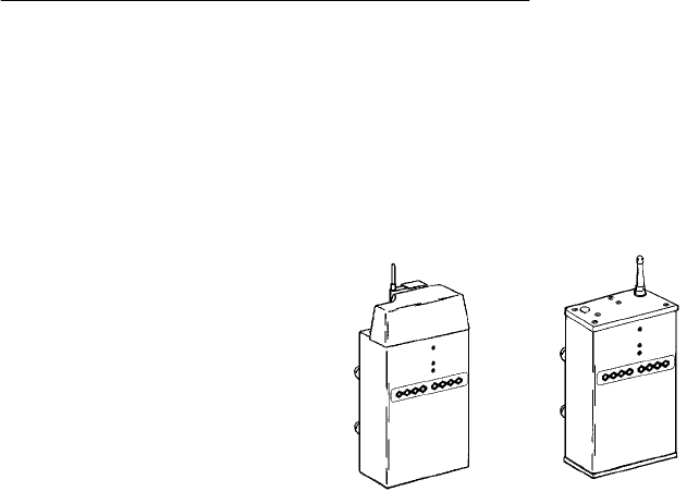
Description
The6710 Access Pointprovidestransparent, wireless
communicationsbetweenawiredEthernetLANand
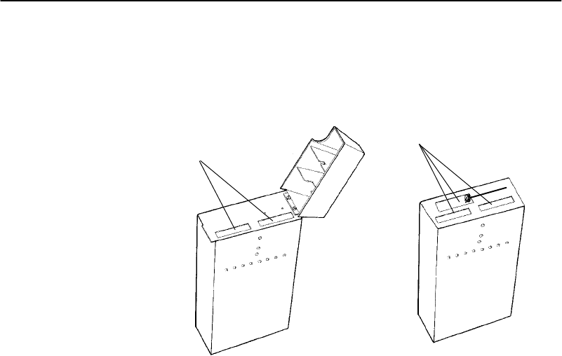
wireless stations.Figure2-1showscurrentdesigns;
informationinthisuser’sguideappliestobothdesigns.
Figure 2-1
6710 Access Points
SECTION2"Featuresand FunctionalOverview
2-26710 Access PointUser’sGuide
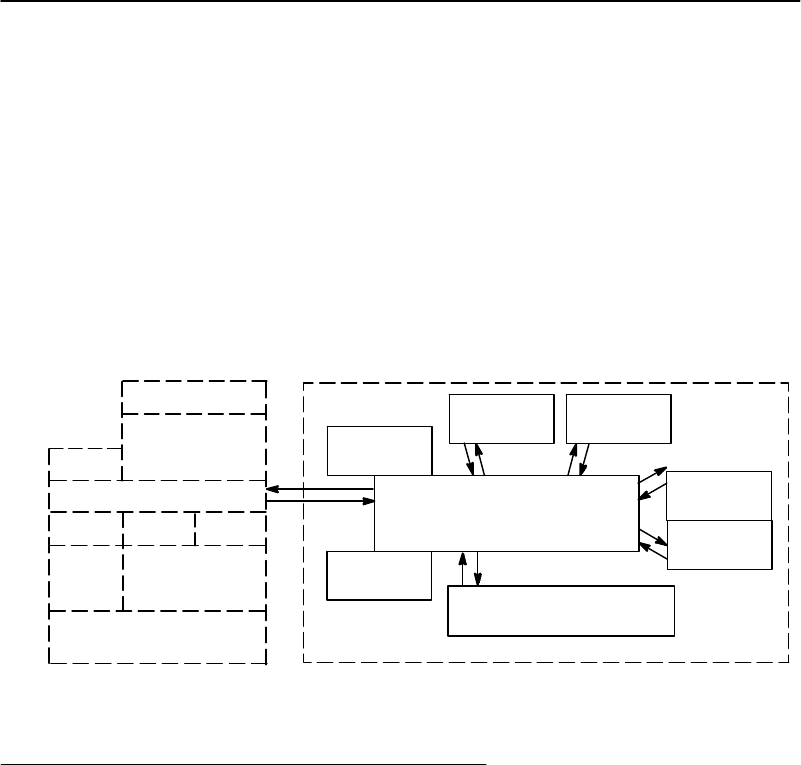
Theaccess pointfunctionsasa 4-port translatingbridge.
Functionalitywithintheaccess pointcanbepartitioned
intotwomajorfunctionalblocks:bridgingfunctionality
andmanagementfunctionality.Bridgingfunctionspertain
totheforwardingofdatathroughtheaccess point.
Managementfunctionalityinvolvesconfiguration,software
upgrade,andnetworkmanagement.
Figure2-2isasimplified diagramshowingthefunctions
withintheaccess point.
Figure 2-2
6710 Access PointFunctions
RS-232 Diagnostics Port
MIB
SNMP
Agent
DHCP
TCP/IP
TFTPHTTPTelnet
Device
Configuration
File
System
Forwarding
Database
Port2
(NIC2)Port3
(NIC1)
Port4
(OWL/IP)
Proxy ARP
Port1
(Ethernet)
Network
Organization
Bridging
AUI10BASE2 10BASE-T
Managementand Configuration Bridging
Bridging Functionality
GeneralConcepts
BridgesarecommoncomponentsinwiredLANs.Bridges
aredevicesthatjointwo ormoreLANsegments.This
providestheappearance ofasingleLANsegment tothe
protocolsandapplicationsthatoperatewithintheLAN.

SECTION2"Featuresand FunctionalOverview
6710 Access PointUser’sGuide 2-3
Bridgesoperateat theMediaAccess Control(MAC)
sublayeroftheDataLinkLayer(Layer2)ofthe
InternationalOrganizationforStandardization(ISO)
protocolmodel. Operatingat theMAC layerallowsbridges
to operatetransparentlytocommonlyusednetwork
protocols suchasTCP/IP,Novell SPX/IPX,NetBEUI,and
DECnet.
InwiredLANs,bridgesdothefollowing:
"Segment trafficforbetterefficiencyand performance.
"ExtendthereachofLANswhencablelengthornode
limitshavebeenreached.
"TranslatebetweendifferentLANtypes suchasIEEE
802.3Ethernetand802.5TokenRing.
ALANenvironmentnormallyconsistsofacollectionof
nodesorstations,eachidentifiedbyaunique48-bit
physicaladdress (alsocalledanIEEE address or MAC
address). Datais sentontheLANasframesorpackets
thatcontainthesource address ofthestationsendingthe
frame,andthedestinationaddress oftherecipientstation.
Abridgehasatleast twoports,eachconnectedtoa
differentLANsegment.Bridgeslearnwhichsource
addressesaregeneratingtrafficoneachoftheirports.If
thebridgereceivesaframewithadestinationaddress
correspondingtoasourceaddress ithas seenonanother
port,itforwardstheframetotheport.Ifitreceivesa
framewherethesourceand destinationaddressesare on
thesameport,itignores(drops)theframe,sincethe
destination nodereceivesthe originaltransmission.
Generally,ifa bridgereceivesaframeforan unknown
destinationaddress onanyoneport,itfloodstheframe on
all otherports.

SECTION2"Featuresand FunctionalOverview
2-46710 Access PointUser’sGuide
Access PointBridging Layer
The6710 Access Pointfunctionsasa bridgewith uptofour
ports:
"AnEthernetport.
"One ortworadioports.
"AnOpenWireless LAN/InternetProtocol(OWL/IP)
port.
Theaccess pointisatranslatingbridgebecauseitforwards
framesbetweenEthernetandwireless mediathathave
uniquephysicalandMAC protocol implementations.The
access pointimplementsthebasiclearningandforwarding
functionsofasimplewiredLANbridge.Italsoincludes
additionalfunctionalitytoaddress uniqueproblemsin
wireless LANs.
Significantfunctions supportedat thebridginglayer
includenetworkorganization,supportfor roamingand
power-managedstations,and programmablefloodinglevels.
NetworkOrganization
Openwireless LANnetworksmaybecomplex,supporting:
"Small orlargenumbersofaccess pointsonasingle
wiredLANbackbone.
"Stationsthatroambetweencoverageareasand
employpowermanagement toimprovebatterylife.
Morecomplextopologiesincludethefollowing:
"Range extensionthroughwireless access points, which
arenotconnectedtothewiredLANbackbone.
"SecondaryLANs(connectionofwiredLANsegments
bywireless links).
"Mixedradiofrequency(RF)media.
"OperationovermultipleIPsubnets.
"Multiple,independentwireless LANsononewired
LANbackbone.

SECTION2"Featuresand FunctionalOverview
6710 Access PointUser’sGuide 2-5
Access pointsautomaticallyconfigureintoaself-organized
networkusingaspanningtree topology.They
automaticallyreconfigurethenetworktomaintainreliable
operationasdevicesareaddedor removed,orinthe event
ofsometypesofwiredLANfailure.Thespanningtree
providesefficient,loop-free forwardingof framesthrough
thenetworkandrapidroamingofmobilestationswithin
thenetwork.
Thespanningtree isinitiatedbythesuper root,anaccess
point thatcoordinatesthenetworkand distributescommon
systemparametersto otheraccess pointsandstations.The
super rootiselectedfromagroupofaccess points
designatedat thetime ofinstallation.The electionprocess
also occursinthe eventofasuper rootfailure,preventinga
singlepointof failure.
Forwarding
Thebridgemaintainsaforwardingdatabase ofall physical
stationaddressesknowntotheaccess point,andthecorrect
portforeachaddress.Thisdatabasemakesefficient
forwardingdecisionsinthebridgingsoftware.
Thedatabaseisupdatedthroughmonitoringaddresseson
eachport,andbymessagesexchangedbetweenaccess
pointswhenstationsroam.Thedatabasealsoincludesthe
powermanagementstatusofeachstation,supportingthe
pendingmessagefeature ofthenetwork.
Pending Messages
Wireless stationsmayusepowermanagement tomaintain
batterylife.Thesestationswakeup periodicallytoreceive
messagesthat mayhavearrivedwhiletheir radiowas
powered down.Thebridgingsoftwareprovidesapending
messagedeliveryservice,allowingframestobehelduntil
thestationisreadytoreceivethem.

SECTION2"Featuresand FunctionalOverview
2-66710 Access PointUser’sGuide
Flooding Configurations
StandardLANbridgesfloodframesonall portswhenthe
destinationaddress isunknown.Additionally,many
networkprotocolsusemulticastaddressingfor connection
andstatuscommunications.Amulticastframeisaspecial
type of framedestinedformorethanonephysicaladdress.
Standardbridgesalwaysfloodmulticastframes.
Mostwireless mediasupportedintheaccess pointoperate
atlowermediaspeedsthanEthernet.Indiscriminate
floodingfroma busyEthernetbackbonetoawireless
mediumcanconsumeasubstantialportionoftheavailable
wireless bandwidth.Thisreduces systemperformance even
thoughfloodedframesarefrequentlynotintendedfor
stationsonagivenwireless segment.
Toallowperformancetuning,theaccess pointprovides
separatefloodingcontroloptionsforboth unicast(single
physicaladdress)andmulticastframes.Access points
servingasdesignatedbridgesconnectingwiredLAN
segmentsmaybeconfiguredtousedifferentflooding
settingsthanaccess points servingonlywireless stations.
Two ofthewireless mediasupportedintheaccess point—
synthesizedUHF(S-UHF)and900 MHz—providereliable
attachmechanisms, whichguarantee thatwireless stations
arealwaysintheaccess point’sforwardingdatabase.
Unicastfloodingisnever requiredforthesestations.
TheWireless LANInteroperabilityForum(WLIF)2.4GHz
optionalsoprovidesareliableattachmechanismfor
stationsusingtheNORANDRNetworkLayer(NNL)
terminalemulation networkprotocol.Multicastflooding
levelsaresetforindividualnetworksbasedontheneedsof
wireless stationstoreceivemulticastframes.Fornetworks
withIPwireless stationsonly,theProxy ARPServer
providesanoptionto enablingmulticastflooding.

SECTION2"Featuresand FunctionalOverview
6710 Access PointUser’sGuide 2-7
Proxy ARP Server
TheProxy ARPServerisanadvancedfloodingcontrol
capabilityforstationsusingIP.AnARP(Address
ResolutionProtocol)isatype ofmulticast messageusedto
determinethephysical(MAC)address ofastation usinga
specificIPaddress.WhenProxy ARPisenabled,theIP
addressesofstationsusingIPareincludedinthe
forwardingdatabase.IfthedestinationIPaddress matches
anentryintheforwardingdatabase,theARPis sent tothe
physicalunicastaddress matchingthatIPaddress.
Toallowcustomizationofthiscapabilityto optimize
performance,theserveroperatesinone ofthefollowing
modes:
"Noflooding.
"Delayedflooding.
"Normalflooding.
Proxy ARPServerisdiscussedinmoredetail inSection4,
“Configuration.”
BridgePorts
Theaccess pointhasthefollowingphysicalports:
"AnEthernetport.
"TwoPCcardslotscapable ofacceptingavarietyof
wireless NetworkInterfaceCards(NICs).
Theaccess pointalsohasalogicalOWL/IPport.
EthernetPort
TheEthernetportcanbeconfiguredtosupport10BASE-T
twisted pair,10BASE2thinnet,oranAUIconnection.The
AUIconnectioncansupport10BASE5thicknetor10BASEF
fiberoptic connectionswiththeappropriatemedia
adapters.

SECTION2"Featuresand FunctionalOverview
2-86710 Access PointUser’sGuide
Thephysicalconnectionsare onthebottompanelofthe
access point.ThedesiredEthernet mediumis selectable
throughthedeviceconfigurationmenus.Section3,
“Installation,”hasmoreinformationaboutconnectingthe
access point toEthernet media.Section4,“Configuration,”
describeshowtoset themedium throughtheconfiguration
menus.
EthernetPortFilters
TheEthernetportcanbeconfiguredtosupportavarietyof
preconfiguredandcustominputfilters.Access pointsare
commonlyinstalledonLANsthatcarrytrafficforwiredand
wireless devices.Settingfilterspreventsunnecessary
trafficfrom thewiredLANfrombeingforwardedontothe
wireless medium.Thisisimportantbecausecommon
wireless technologiesoperateatdataratesbelowEthernet
speeds.
Normally,filtersareset topass trafficknowntobe(or
likelytobe)destinedforwireless stations,anddroptraffic
notdestinedforstationsrequiringwireless connectivity.
FilteringoccursintheEthernetdriversoftwarethat
controlslowleveloperationoftheEthernetports,
minimizinginvolvementofotherfunctionswhen
unnecessaryframesarereceived.Inmostinstallations,the
predefinedfiltersareused.Thedefaultaccess point
configurationsetsnofilters.Filtersetupisdiscussedin
moredetail inSection4,“Configuration.”
Filteringandfloodingcontrol(describedonpage2-6)are
complimentarybuthavedifferentfunctions.Filtersallow
framestobe eliminatedbaseduponcontentoftheframe,
usuallythenetworkprotocolheaderfieldswithintheframe.
Forexample,filterscanbeset to eliminatesome orall IP
trafficorNovell IPXtraffic.

SECTION2"Featuresand FunctionalOverview
6710 Access PointUser’sGuide 2-9
Filteringoccursregardless ofwhetherthedestination
address isintheforwardingdatabase.Usingfilterscan
improvetheperformance oftheaccess pointand prevent
undesiredframesfrombeingforwardedtowireless stations
attachedtotheaccess point.
Floodingdecisionsaremadeafterframeshavebeen
receivedonaportandfiltered.Floodingsettingsdetermine
howtheaccess pointforwardsframestodestination
addressesnotintheforwardingdatabase.
RadioPorts
Eachofthetworadioportsintheaccess pointarea
connectionintoaLANsegmentconsistingofall wireless
stationsandaccess pointsthatusethesamewireless
technology,arewithinwireless communicationsrange of
theaccess point,andareconfiguredtocommunicate
together.
ThetwoPCcardslotsareintendedforwireless NICsand
aredesignatedasNIC1 andNIC2.Internally,theyare
configuredasPort3 andPort2,respectively.Thefollowing
wireless optionsarecurrentlysupported:
"WLIF(2.4GHz).
"900 MHz.
"450 MHzS-UHF.
Thedifferent mediaoptionsprovidealternativecoverage
andthroughput tradeoffs.Radiomediaoptionsare
describedinmoredetail inAppendixesB,C,andD.
Theaccess pointalsosupportscombinationsoftwoadapters
foroperationinmixedmediasystems;or,forWLIFradios,
awireless access pointcapability.Thefollowingdualradio
configurationsaresupported:
"WLIFand900 MHz.
"WLIFandS-UHF.
"WLIFandWLIF(limitedtoMaster/Slave
configurationforwireless access points).

SECTION2"Featuresand FunctionalOverview
2-10 6710 Access PointUser’sGuide
Configurationofindividualradio optionsandtheWLIF
wireless access pointconfigurationarediscussedinSection
4,“Configuration.”
OWL/IP Port
TheOWL/IPportisalogicalportusedininstallations
wherethewireless infrastructureisrequiredto operate
across multipleIPsubnets;thatis,ininstallationswhere
IProutersareused.
TheOWL/IPportisanadvancedcapabilitythatallows
stations supportingIPandnonroutableprotocols suchas
NNL(usedinsometerminalemulationinstallations)to
roamwithoutlosingconnectivitywhenawireless LAN
installationmustextendovermultipleIPsubnets.Insome
cases, OWL/IPmayalsoprovideconnectivityinlarger,
routednetworkswhenroamingbetweenIPsubnetsisnot
required,butwhereitisdesirabletoconfigureasingle
wireless networkacross routerboundaries.
OWL/IPusesGeneralRouterEncapsulation(GRE),a
registered protocolfrom theTCP/IPprotocolsuite. GRE
allowsframesdestinedforstationsonadifferentIPsubnet
tobeencapsulatedwithanIPaddress thatpasses
transparentlythroughrouters.Encapsulationisalso
sometimesreferredtoastunneling.
Tosimplifyconfiguration, OWL/IPfunctionalityistreated
asanadditionalportwithintheaccess pointarchitecture.
Itisalogicalportinthat thereisnophysicalradio orwired
LANportassociatedwithOWL/IP.
Encapsulatedframesmaybesent throughanyofthethree
physicalports.Access points separatedbyone ormore
routersmaybethoughtofasoriginatingandreceiving
nodesonthetwosidesofatunnelthatisestablished
throughtherouter.

SECTION2"Featuresand FunctionalOverview
6710 Access PointUser’sGuide 2-11
Theforwardingdatabase entryforastationonthe other
side ofthetunnel includesthephysicalport(NIC1,NIC2,
orEthernet)theframeshouldbeforwardedthrough,and
anindicationthatencapsulationisrequired.Thereceiving
access pointonthe otherside ofthetunnelde-encapsulates
theframeandthenforwardsitonthecorrectphysicalport.
OWL/IPisdescribedinmoredetail inSection4,
“Configuration,”andAppendixE,“OWL/IP.”
Configuration and Management
Configuration
Theaccess pointcanbeconfiguredthroughalocalRS-232
connection,or remotelythroughaTCP/IPconnection.The
access pointincludesacommandmonitorandmenu driven
configurationwithonlinehelp.Thecommandmonitorand
filesystemconfigurationarecontainedinpermanent
read-onlymemory(ROM)withintheaccess point,andcan
beaccessedthroughtheRS-232 diagnosticsportevenif
softwareisnotloadedintheaccess point.
Mostaccess pointfunctionalityisprovidedbythesoftware
storedwithinthefilesystem.Configurationparameters
arestoredin nonvolatileEEPROMmemory,andare
maintainedinthe eventofpowerloss.
Diagnostics and Configuration Port
AnRS-232 configurationportisprovidedfordirectaccess to
theaccess point’scommandmonitorandconfiguration
menus.Access throughthediagnosticsportis
password-protectedforsecurity.

SECTION2"Featuresand FunctionalOverview
2-12 6710 Access PointUser’sGuide
TheportusesastandardPC ATstylecable,andoperatesat
speedsupto57.6Kbps.Configuration usingthisportis
describedinSection4,“Configuration.”
RemoteAccess
Remoteaccess isavailable overTCP/IPconnectionsusing
TelnetorHypertextTransferProtocol(HTTP) for
configurationmanagement,andSimpleNetwork
ManagementProtocol(SNMP) fornetworkmanagement.
TCP/IP
Theaccess pointsupportsremoteaccess throughaRequest
forComments(RFC)compliantTCP/IPstack.Beforeinitial
usage,thestackmustbeinitiallyconfiguredwithanIP
address andanoptionaldefaultrouterthroughtheRS-232
diagnosticsport.Alternatively,theaccess point maybe
configuredwithaDynamicHostConfigurationProtocol
(DHCP)servername.Theaccess point thenobtainsitsIP
address,defaultrouter,andsubnet maskfromaDHCP
server.
DHCPClient
Theaccess pointcontainsaDHCPclient,allowingit to
receiveanIPaddress overthenetwork.TheDHCPclient
supportstemporaryand permanentleases.Italsoaccepts
permanentleasesfromaBootstrapProtocol(Bootp)server.
See Section4,“Configuration,”forfurtherdetail onDHCP
operation.
Telnet
Telnet maybeusedtoaccess theaccess point’s
configurationmenus.Thecommandinterfaceisidenticalto
thecommandinterfacethroughthediagnosticsport.See
Section4,“Configuration,”formoreinformationabout
access throughTelnet.

SECTION2"Featuresand FunctionalOverview
6710 Access PointUser’sGuide 2-13
HTTP
Theaccess pointsupportsconfiguration usingHTTP froma
workstationequippedwithaWeb browser.Internet
ExplorerorNetscapeNavigatorisrecommended.See
Section4,“Configuration,”formoreinformationabout
access throughaWeb browser.
ElectronicSoftwareDistribution
Theaccess pointsupportselectronicsoftwaredistribution,
whichallows softwareupgradesafterinstallation.The
access pointprovidesadualbankfilesystemwithone
activebankandoneinactivebank.Itoperatesfrom the
activebank,allowingsoftwareupgradestobestoredinthe
inactivebank.Thisenablesupgradestobeloadedwhile
theaccess pointisoperating.
Theupgradecanbestartedimmediatelyafterdownloading
byswappingtheactiveandinactivebanksandrebooting.
Theaccess pointcanalsobeprogrammedtoloadthenew
softwareatalatertime,suchasafterall access pointshave
been upgradedorduringatime oflittlesystemactivity.
TFTPClientand Server
SoftwaredownloadsareaccomplishedusingtheTrivialFile
TransferProtocol(TFTP),anothermemberoftheIPsuite.
Eachaccess pointcontainsaTFTP clientandserver.The
TFTP clientallowstheaccess point to obtainsoftware
updatesfromaTFTP server.Theserver canbeanaccess
pointconfiguredwiththeTFTP serverenabled,oranother
networkworkstationwithTFTP server capability.
Scripting
Theaccess pointsupportsascriptingcapabilitythat
automatesmostofthesoftwaredownload process.Scripts
canbeuploadedtotheaccess point throughTelnetor
SNMP.

SECTION2"Featuresand FunctionalOverview
2-14 6710 Access PointUser’sGuide
NetworkManagement
Theaccess pointisinstrumentedfornetworkmanagement,
withvariablesdefinedintheManagementInformation
Base(MIB).TheMIBisSNMPV1compliant.
Managementinformationcanbeaccessedthroughthe
SNMPagent.TheMIBmaybe orderedseparatelyand
compiledforanySNMPnetworkmanagementplatform.
AdditionalcapabilitiesaresupportedintheOWLView
networkmanagementapplicationforHPOpenView.
AppendixG, “MIB,”containsthe6710 Access PointMIB.
Consult thefollowingdocumentationformoreinformation
on networkmanagement:
"NORAND OpenWireless LANwithHPOpenViewfor
WindowsUser’sGuide(961-051-009)
"OWLViewforHPOpenViewforUNIXUser’sGuide
(961-051-011)
"OWLViewforHPOpenViewforWindowsUser’sGuide
(961-051-010)
SampleConfiguration
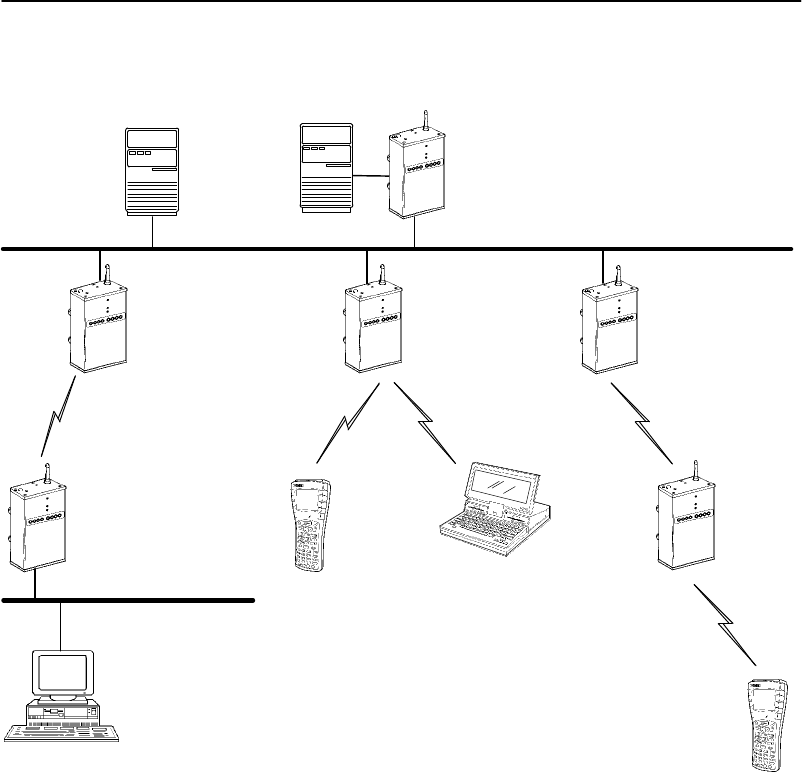
Figure2-3showsasamplenetworkconfiguration.Italso
showsaccess pointsprovidingadditionalcoverageand
wireless linkstosecondaryEthernetLANs.
"NOTE:ConsultAppendixD,“S-UHFSpecificationsand Antennas,”for
network configuration limitationsforS-UHFsystems.
SECTION2"Featuresand FunctionalOverview
6710 Access PointUser’sGuide 2-15
Figure 2-3
SampleNetworkConfiguration
SecondaryEthernetLAN
6710 Access Point
(DesignatedBridge)
6710 Access Point
PEN*KEYR6400
Computer
Desktop
LAN ServerTerminalEmulation
Gateway
Host
Notebook
(WLIF)
6710 Access Points
Distribution LAN
PEN*KEY 6400
Computer
Wireless Hop
SECTION2"Featuresand FunctionalOverview
2-16 6710 Access PointUser’sGuide
Components
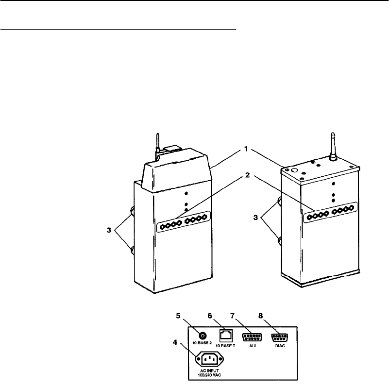
Figure2-4showsaccess pointcomponents,describedonthe
followingpages.Notshownisthemountingbracket, which
attachestheaccess point toawall or ceiling.
Figure 2-4
Access PointComponents
SECTION2"Featuresand FunctionalOverview
6710 Access PointUser’sGuide 2-17
1.Protectivecover.ThecoverprotectstwoTypeII or
TypeIII PCcardslots.Figure2-5showswherethe
slotsarelocated.
Figure 2-5
PC CardSlots
1.PCcardslots
11
2.Indicatorlights.Fourpairsofindicatorlights
(LEDs)onthefrontpanelshowthestatusofthe
access point. Duringthepower-upsequence,the
lights showtheresultsofthepower-upselfdiagnostics
and provideinformationabout the operatingstatus.
Afterthepower-upsequence,thelights showthe
currentoperatingstatusandindicateifaproblem
exists.Section6,“IndicatorLights,”describesthe
lightsindetail.

SECTION2"Featuresand FunctionalOverview
2-18 6710 Access PointUser’sGuide
3.Rubberfeet.Fournonskidrubberfeetprovidea
stablebasefortheaccess pointwhenyouplaceitona
desktoporotherhorizontalsurface.
Whenthemountingbracketisinstalledforanaccess
point mountedverticallyorontheceiling,therubber
feetprovideasmall amountoftensiontothebracket
tohelpholditinplace.
4.ACINPUT.TheAC INPUTconnectorisastandard
IEC type,three-prongAC inputconnector.Thepower
cordattachestothisconnector.Theinternalpower
supplyisanautosensinginternationalpowersupply.
Itacceptsasourcevoltagebetween85 and264 Vac,
withafrequencybetween47 and63 Hz.
5.10 BASE2.The10 BASE2portisastandardBNC
port throughwhichtheaccess pointconnectsto
10BASE2Ethernet(thinnet).
6.10 BASET.The10 BASETportisastandardRJ45
port throughwhichtheaccess pointconnectsto
10BASE-T(UTP)Ethernet.
7.AUI.TheAUIportisa 15-pin, D-subminiature
(D-sub)port.Theaccess pointconnectstoanAUI
networkadaptorthroughthisport,for connectionto
10BASE5Ethernet(thicknet).AppendixF,“Portand
CablePin-Outs,”containspindefinitions.
"NOTE:Section 3,“Installation,”showshowtoconnect the access point to
10BASE2,10BASE5,and 10BASE-T.
8.DIAG.TheDIAGportisa 9-pinD-sub
communicationport thatcommunicatesatRS-232
levels.Usethisport toconfiguretheaccess point,
downloadnewsoftware,andretrievestatistics.
AppendixFcontainspindefinitions.

SECTION2"Featuresand FunctionalOverview
6710 Access PointUser’sGuide 2-19
Accessories
PowerCord
Thepower cordconnectstheaccess point tothewall outlet.
Thefollowingchartlistspower cord partnumbers.
CountryPartNumber
Australia 321-472-001
Denmark321-501-001
Europe321-473-001
Italy321-471-001
Germany321-515-001
UnitedKingdom321-474-001
UnitedStates321-054-001
IndustrialLocking Mounting
Bracket
TheIndustrialLockingMountingBracket “locks” theaccess
pointintothebracket.Thisbracketisrecommendedfor
installationswherevibration,shaking,orothermovement
candislodgetheaccess pointfromitsmount.
ItemPartNumber
Mountingkit203-386-001

SECTION2"Featuresand FunctionalOverview
2-20 6710 Access PointUser’sGuide

6710 Access PointUser’sGuide 3-1
Section 3
Installation
""""""""""""""""""""""""""""
This sectiondescribeshowto:
"Checktheaccess point’sdefaultconfiguration.
"Preparefortheinstallation.
"Collect thenetworkingequipmentyou need.
"Findthebestlocation.
"Connect totheEthernet medium.
"Install PCcards.
"Applypower.
Checking theDefaultConfiguration
Theaccess pointis shippedwithdefaultsettingsforsystem
softwareparameters, whicharelistedinSection4,
“Configuration.”Youmayneedtochangesomedefault
settingstoachieveamore efficientconfigurationforyour
site.See Section4forinformationaboutreconfiguringthe
access point.Theaccess pointshouldbeproperly
configuredbeforeitisconnectedtothenetwork.

SECTION3"Installation
3-26710 Access PointUser’sGuide
Preparing fortheInstallation
"NOTE:Someone who knowsand understandsall applicablelocalbuilding
codesand isproficientwiththe toolsand equipmentused toinstall
FCC Class Belectromechanicaldevices should physicallyinstall the
access point.
Beforeyouinstall theaccess point,unpackitandinspectit
fordamage ormissingparts.Saveall thepaperworkyou
received.Iftheaccess pointappearstobedamaged,contact
theCustomerResponseCenterforinstructionson
returningtheunitfor replacement.
Theshipmentcontainstheaccess pointwithFLASHand
thefollowingitems:
"Mountingbracket
"AC power cord
"Warrantycard
Collecting theEquipment
Beforeyouinstall theaccess pointontothenetwork,collect
the equipmentyouwill need.
EthernetLAN Components
Theaccess pointdirectlyconnectsto10BASE2,10BASE-T,
or10BASE5Ethernet medium.Consultacablingreference
formaximumrun lengthsandnodelimitsforEthernet
wiring.
SECTION3"Installation
6710 Access PointUser’sGuide 3-3
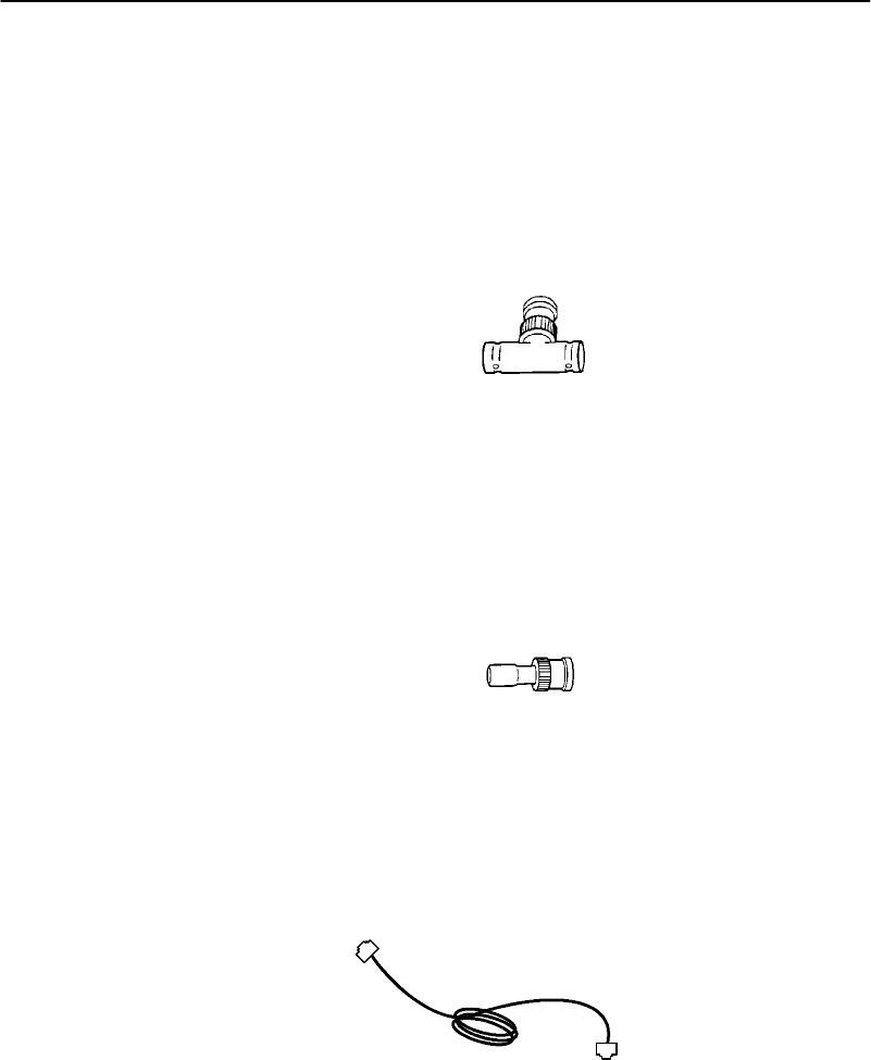
10BASE2Components
10BASE2componentsincludeaT-connector,acable
terminator,andtheproperlengthsof10BASE2coaxcable.
The10BASE2T-connector(Figure3-1)attachestothe
access point’s10BASE2port,andconnectstheaccess point
tothemiddle orendof10BASE2cable.
Figure 3-1
T-Connector
Acableterminator(Figure3-2)attachestothe
T-connector.Itisrequiredforadeviceconnectedtothe end
of10BASE2cable.Theterminatorproperlyterminatesthe
networkcabletomaintainproperimpedance.Proper
terminationisnecessaryfor reliableEthernetoperation.
Figure 3-2
CableTerminator
10BASE-TComponent
10BASE-Tcoax cableisnormallyusedtoconnect the
access point toanEthernethub.ThecablehasanRJ45
plugoneachend(Figure3-3).
Figure 3-3
CableWithRJ45 Plugs
SECTION3"Installation
3-46710 Access PointUser’sGuide
10BASE5Components
10BASE2componentsincludetheproperlengthsof
10BASE5coaxcable,anAUIdropcable(less thanorequal
to50 feet/15 meterslong),andatransceiver.Twotypesof
transceiversaretheintrusiveN-Seriestransceiverandthe
nonintrusivevampiretap.
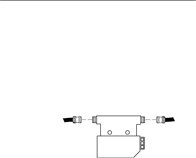
TheN-Seriestransceiver(Figure3-4)isaT-shaped
connectorwitha 15-pinAUIportandtwotypeN
connectors.Thistransceiverisintrusivebecausenetwork
serviceisdisruptedwhilethecoaxialcableiscutanda
threadedN-seriesconnectorplacedoneachendofthecable.
A10BASEF(fiberoptic)adaptermaybeattached directly
totheAUIconnector.
Figure 3-4
N-Series Transceiver
Thevampiretapisaninsulation-piercingclamp devicethat
clampsontothecoaxialcable(Figure3-5).Thevampiretap
piercesthecoaxialcable’sinsulationandmakescontact
withtheshieldandinner conductorwithoutcuttingthe
cable.

SECTION3"Installation
6710 Access PointUser’sGuide 3-5
Figure 3-5
VampireTap
Communication Equipment
Youcanaccess theaccess point’s systemsoftware
configurationmenuslocallythroughtheunit’sDIAGport,
or remotelythroughaTelnetsessionorWeb browser.
LocalDIAGPortAccess
Forlocalaccess,you needthefollowing:
"Third-partycommunications softwareterminal
emulationpackagewithY-modemcapability(suchas
PROCOMM PLUSbyDataStormTechnologies,Inc.).
Install theprogramaccordingtoitsuserguide.
"PC(personalcomputer)station, whichshouldmeet
therequirementsoutlinedintheuserguideforthe
terminalemulationprogram.
"Cabletoconnect thePCtotheaccess point’sDIAG
port.Thefollowingchartlistscables.

SECTION3"Installation
3-66710 Access PointUser’sGuide
ForthisPCPortUseCablePartNumber
9-pin226-106-001 (null modemcable)
25-pin321-355-001
Telnet
You needthefollowingtoaccess theconfigurationmenus
throughaTelnetsession:
"PCorworkstationwithaninstalledandconfigured
networkinterfacecardandaTelnetapplication.You
canalsouseahostcapable ofactingasaTelnetclient.
"TelnetVTemulator(TNVT)installedonthePC.
"IPaddress fortheaccess point.See Section4formore
informationaboutIPaddresses.
WebBrowser
Theaccess point’sconfigurationmenusaredesignedfor
HTML Level2.0orhigher.You needthefollowingtoaccess
theconfigurationmenusthroughaWeb browser:
"Graphicalbrowserapplication.
"Internetorlocalnetworkconnection.
"IPaddress fortheaccess point.See Section4formore
informationaboutIPaddresses.
NetworkManagementPlatform
Tomanagethesystem throughanetworkmanagement
platform,you needtheplatform(suchasOpenViewfor
WindowsbyHewlett-Packard)installedonanetwork
managementstation usingSNMP.Thestationmust meet
therequirementsoutlinedintheplatform’suserguide.

SECTION3"Installation
6710 Access PointUser’sGuide 3-7
Finding theBestLocation
SiteSurvey
IntermecstronglyrecommendsthatIntermecor certified
providersconductasitesurveytodeterminetheideal
locationsforall ofyournetworkcomponents.Apropersite
surveyrequires specialequipmentandtraining.Asite
surveyprovidesaninstallationrecommendationthat
addressesvariousfactors, whichcanaffect theperformance
ofyourwireless LANsystem.
General Installation Guidelines
Coverageinmostsitesrequiresanetworkofaccess points
tobeinstalled.Radiocoveragevariesgreatlywithfactors
suchasbuildingconstruction,numberandtype of
obstructionsinthesignalpath,andtheRFmediain use.
Additionalfactorsrelatedtotheintendeduse ofthesystem
alsodictateinstallationpractices.Thefollowing general
practices shouldbefollowedinanyinstallation:
"Locateaccess pointscentrallywithinareasrequiring
coverage.
"Trytopositiontheaccess pointsoitsindicatorlights
arevisible.Thelightsareusefulfortroubleshooting
theinstallation.
"Positionantennasbelowrooftrussesandawayfrom
I-beams,racks,orotherstructuresandobstructions.
"Overlapaccess pointcoverageareastoavoidcoverage
holes.
"Install wiredLANcablingwithin nodelimitandcable
lengthlimitations.

SECTION3"Installation
3-86710 Access PointUser’sGuide
"Ensurethatapoweroutletiswithin6feetofthe
access point.An uninterruptablepowersupplyis
recommendedwhentheacpowersystemisnot
reliable.
"EnsurethatLANandac cablescanreachtheaccess
pointafteryouinstall it.Leavesufficientroom
aroundtheaccess pointsoyoucaneasilyattachand
removecables.
"Donotlocateanaccess pointwiththeS-UHFradio
optioninacomputer room.RFemissionsfrom the
higherspeed processorsincurrent-generation
computersmayreducesystemrange.
Mounting theAccess Point
Youcanmount theaccess pointhorizontallyonatabletop,
verticallyonawall orpost,orontheceiling.
Horizontal(Tabletop)Mount
1.Removethemountingbracketfrom thebottomofthe
access point.Thebracketisnotneededforatabletop
installation.
2.Set theaccess pointinposition.Theunitrests
securelyonfour rubberfeet thatkeepitfromslipping
outofplace.
3.Makeall Ethernetconnections.See “Connectingto
Ethernet” onpage3-10.
4.Makeall power connections.See “ApplyingPower”on
page3-20.
5.Watchtheindicatorlightstoverifythat theaccess
pointisworkingproperly.See Section6,“Indicator
Lights,”forhelp.
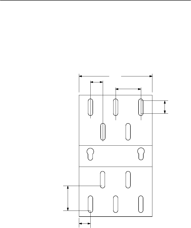
SECTION3"Installation
6710 Access PointUser’sGuide 3-9
Verticaland Ceiling Mounts
See Figure3-6 andtheprocedurefollowingit.
"NOTE:If mounting the access pointon a hollow wall,securethe mounting
platetoa3/4” (thick)plywood base byfour1”X1/4”nuts,bolts,and
washers.Anchorthe plywood basetotwoseparatewall studsby
four2”X1/4”diameterlag screws(twolag screwsin eachstud).
Figure 3-6
Mounting Bracket
6.00"
1.00"
2.00"
1.00"
1.00"
2.00”

SECTION3"Installation
3-10 6710 Access PointUser’sGuide
1.Inspectwheretheaccess pointwill bemountedand
determinewhathardwareisneeded. Different
surfaces suchasdrywall, wood,andconcreteblock
requiredifferent mountinghardware.Forthisreason,
auniversalmountingbracketisincludedwiththe
access point.
2.Removethemountingplatefrom thebottomofthe
access point.
3.Usingthemountingplateasatemplate,markwhere
theanchorsthatsecurethemountingplatetothe
surfaceshouldbelocated.
4.Attachtheaccess point mountingplatetothewall or
ceilingwith2Ix1/4Idiameterlagscrewsorbolts,
dependinguponthesurface.Themountingplate
mustbesecuredtothesurfacebyatleastfour
anchors,one oneachcorner.
5.Reattachtheaccess point tothemountingplate.
6.Makeall Ethernetconnections.See “Connectingto
Ethernet.”
7.Makeall power connections.See “ApplyingPower”on
page3-20.
8.Watchtheindicatorlightstoverifythat theaccess
pointisworkingproperly.See Section6,“Indicator
Lights,”forhelp.
"NOTE:An optional locking kitisavailable.See Section 2,“Featuresand
FunctionalOverview,”for moreinformation.
Connecting toEthernet
Thefollowingpages showhowtoconnect theaccess point to
10BASE2,10BASE5,and10BASE-TEthernet.
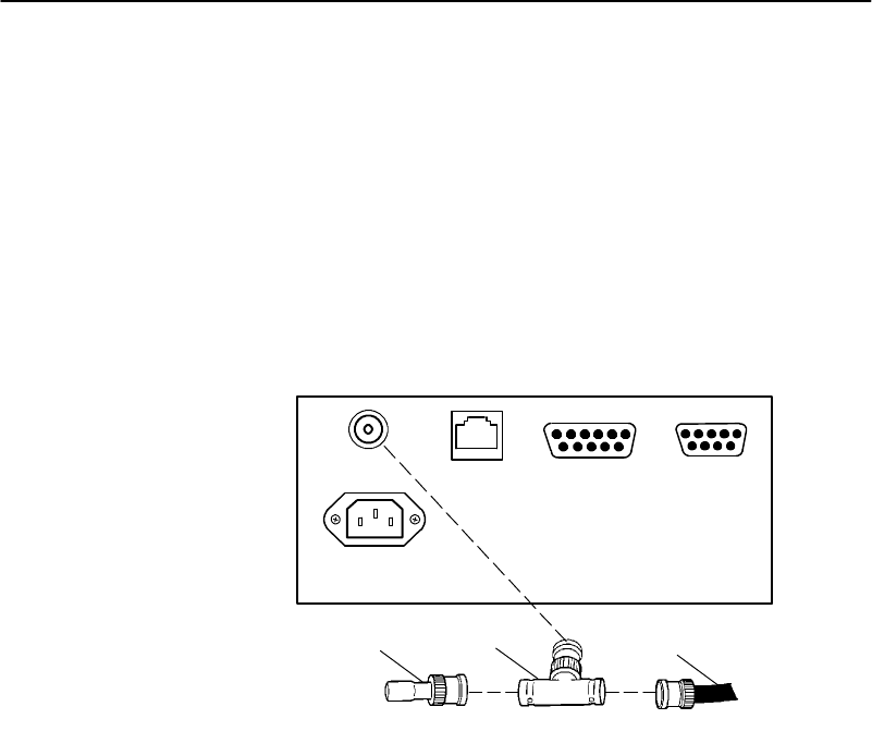
SECTION3"Installation
6710 Access PointUser’sGuide 3-11
10BASE2Ethernet
Theaccess pointconnectstothe endormiddle ofthe
10BASE2cablesegment.
"NOTE:Cablelengthsbetween networkdeviceson the 10BASE2Ethernet
LANmustmeetANSI/IEEE standards.
End ofSegment
See Figure3-7 andtheprocedurefollowingit.
1.Cableterminator(50 ohm)
2.T-connector
3.10BASE2 cable
31 2
Figure 3-7
End of10BASE2Segment
10 BASE 210 BASE T
AC INPUT
100/240 VAC
AUIDIAG
1.PlugtheT-connector(2)intothe10 BASE2port.
2.Plugone endoftheEthernetcable(3)intoanopen
endoftheT-connector.Alignthenotchesinthecable
endwiththepostsontheT-connector,pushthecable
in,andtwistone-quarterturn.
3.Plugthecableterminator(1)intothe otherendofthe
T-connector.
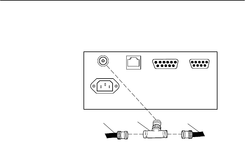
SECTION3"Installation
3-12 6710 Access PointUser’sGuide
MiddleofSegment
See Figure3-8 andtheprocedurefollowingit.
Figure 3-8
Middleof10BASE2Segment
10 BASE 210 BASE T
AC INPUT
100/240 VAC
AUIDIAG
11 2
1.10BASE2 cable
2.T-connector
1.PlugtheT-connector(2)intothe10 BASE2port.
2.Plugone endoftheEthernetcoaxialcable(1)intoan
openendoftheT-connector.Alignthenotchesinthe
cable endwiththepostsontheT-connector,pushthe
cablein,andtwistaboutone-quarterturn.
3.Plugthe endofanotherEthernetcoaxialcable
segmentintothe otheropenendoftheT-connector.

SECTION3"Installation
6710 Access PointUser’sGuide 3-13
10BASE5Ethernet
Theaccess pointconnectsto10BASE5throughanN-Series
transceiverorvampiretap.
"NOTE:Cablelengthsbetween networkdeviceson the 10BASE5Ethernet
LANmustmeetANSI/IEEE standards.
N-Series Transceiver
See Figure3-9 andthefollowingprocedure.
1.Attachone endofthedropcable(1)totheAUIport.
2.Routethedropcabletothe10BASE5cable(4)and
determineasuitablespot tocut thecableandattach
thetransceiver(3).
3.Attachthetransceivertothe10BASE5cable,then
connect the otherendofthedropcabletotheAUIport
(2)onthetransceiver.
VampireTap
See Figure3-10 andthefollowingprocedure.
1.Attachone endofthedropcable(1)totheAUIport.
2.Routethedropcabletothe10BASE5cableand
determineasuitablespotonthecabletoattachthe
vampiretap(3).
3.Attachthevampiretaptothe10BASE5cable,then
connect the otherendofthedropcabletotheAUIport
(2)onthetap.
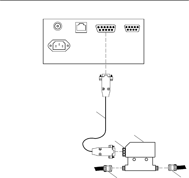
SECTION3"Installation
3-14 6710 Access PointUser’sGuide
1
2
Figure 3-9
N-Series Transceiver
1.Drop cable
2 15-pinAUIport
3.N-Series transceiver
4.10BASE5 coax
44
10 BASE 210 BASE T
AC INPUT
100/240 VAC
AUIDIAG
3
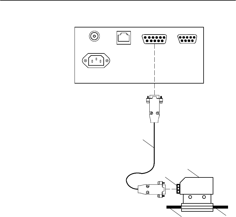
SECTION3"Installation
6710 Access PointUser’sGuide 3-15
1
2
Figure 3-10
VampireTap
1.Drop cable
2.15-pinAUIport
3.Vampiretap
4.10BASE5 coax
44
10 BASE 210 BASE T
AC INPUT
100/240 VAC
AUIDIAG
3
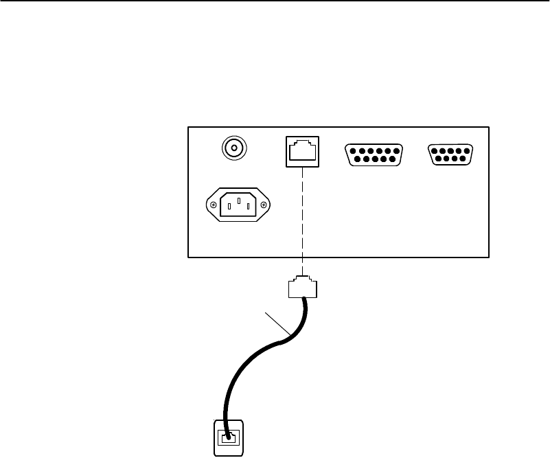
SECTION3"Installation
3-16 6710 Access PointUser’sGuide
10BASE-TEthernet
See Figure3-11 andtheprocedurefollowingit.
1.CablewithRJ45 plugs
2.RJ45 jack (orhub port)
1
Figure 3-11
10BASE-T
10 BASE 210 BASE T
AC INPUT
100/240 VAC
AUIDIAG
1.PlugthecablewithRJ45 jacks(1)intothe10 BASET
port.
2.Plugthe otherendofthecableintoRJ45 jackorhub
port(2).
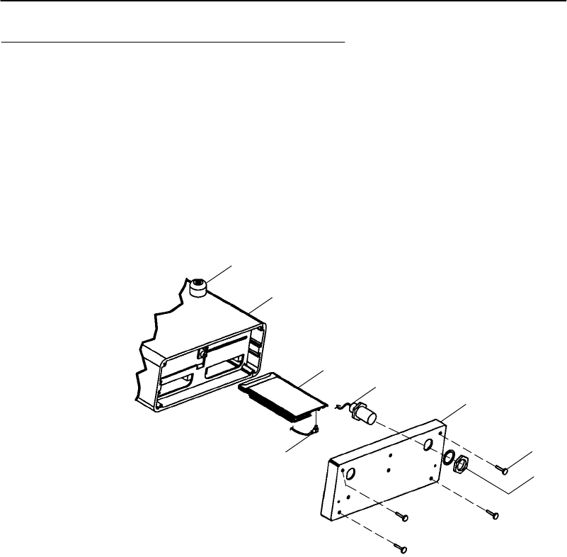
SECTION3"Installation
6710 Access PointUser’sGuide 3-17
Installing PC Cards
Thefollowingpagesdescribehowtoinstall WLIF,900 MHz,
andS-UHF PCcards.
WLIF
TheWLIFradio optionisaTypeIII PCcardthatcanbe
installedineitherslot.Toinstall thecard,see Figure3-12.
2
345
1
46
7
1.Nonskidrubberfeet (4)
2Access point (no radio)
3.PCcard(RM180)
4.Antenna cable
5.End plate
6.4--40 captive thumbscrews
7.Hex nutand lock washer(suppliedwithantenna cable)
Figure 3-12
WLIFPC CardAssembly
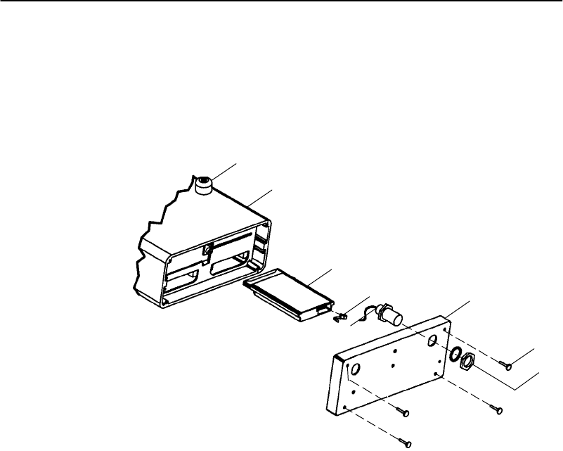
SECTION3"Installation
3-18 6710 Access PointUser’sGuide
900 MHz
The900 MHzradio optionisaTypeIII PCcardthatcanbe
installedineitherslot.Toinstall thecard,see Figure3-13.
Figure 3-13
900 MHzPC CardAssembly
3
2
1
6
7
4
4
1.Nonskidrubberfeet (4)
2Access point (no radio)
3.PCcard(RM160)
4.Antenna cable
5.End plate
6.4--40 captive thumbscrews
7.Hex nutand lock washer(suppliedwithantenna cable)
5
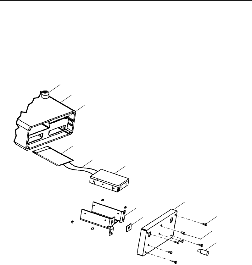
SECTION3"Installation
6710 Access PointUser’sGuide 3-19
S-UHF
TheS-UHFradio optionisaTypeII PCcardthatcanonly
beinstalledintheleft-handslot(withLEDsfacingdown).
Toinstall thecard,see Figure3-14.
1
Figure 3-14
S-UHFPC CardAssembly
2
6
4
7
8
9
10
11
3
5
12
1.Nonskidrubberfeet (4)
2Access point (no radio)
3.Sliding latch(openforRM111 adapter)
4.PCcard(RM111)
5.Flex circuit
6.RM111 adapter
7.Radio bracket
8.Conductive washer
9.End plate
10.4--40 captive thumbscrews
11.4--40x.25 PH
12.Antenna adapter

SECTION3"Installation
3-20 6710 Access PointUser’sGuide
Applying Power
BCAUTION:NEVERremove the coverof the access pointwith power
applied.ALWAYS make the access pointconnection before
making the connection at the source (“loadtosource”).
Damagetotheradio orotherdevices can occurwiththe cover
removed.
"NOTE:Connect the access point to an uninterruptable powersource—a
powersourcethatcannotbe inadvertentlyturned off orotherwise
disconnected.
Powerisappliedtotheaccess point throughthegrounded
AC INPUTconnector.See Figure3-15 andthefollowing
procedure.
1.Plugthereceptacle endofthepower cord(1)intothe
AC INPUTconnector.
2.Insert thethree-prongplugonthe otherendofthe
power cord(2)intoagrounded poweroutlet.
3.See Section6,“IndicatorLights,”fordescriptionsof
theindicatorlights.
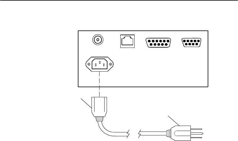
SECTION3"Installation
6710 Access PointUser’sGuide 3-21
Figure 3-15
AC PowerInputConnection
1
2
1.Receptacleon powercord
2.Three-prong plug
10 BASE 210 BASE T
AC INPUT
100/240 VAC
AUIDIAG

SECTION3"Installation
3-22 6710 Access PointUser’sGuide

6710 Access PointUser’sGuide 4-1
Section 4
Configuration
""""""""""""""""""""""""""""
This sectiondescribeshowto:
"CreatealocalDIAGport,Telnet,andWeb browser
sessionwiththeaccess point.
"Access theaccess point’sFLASHandROM.
"Setuptheaccess point throughitsconfiguration
menus.
Youcanconfiguretheaccess pointlocallythroughitsDIAG
port,or remotelythroughTelnetoraWeb browser.The
followingchartshowsthesessionsyoucan usetodo other
tasks.
TaskDIAGPortTelnetBrowser
Changeconfigurationpass-
wordsÖ Ö Ö
ModifytheconfigurationÖ Ö Ö
UpgradeFLASHÖ Ö
ChecktheFLASHversionÖ Ö
Access ROMÖ
ChecktheROMversionÖ
Use onlinehelpÖ Ö Ö

SECTION4"Configuration
4-26710 Access PointUser’sGuide
Onlyonetype ofsessioncanberunningatatime.For
example,ifsomeonestartsaTelnetsessionwhilesomeone
elseisconfiguringtheaccess point throughitsDIAGport,
theconfigurationthroughtheDIAGportwill terminate.
Creating aLocalDIAGPortSession
Insummary,youestablishalocalDIAGportsessionwith
theaccess point throughaVT100 terminalemulation
program.Mostgeneralpurposecommunications software
(suchasPROCOMM PLUS)supportsthisemulation.
Tocreateasession,see Figure4-1 andtheprocedure
followingit.Youshouldcarefullyreviewtheprocedurefirst
tobecomefamiliarwiththeprocess.
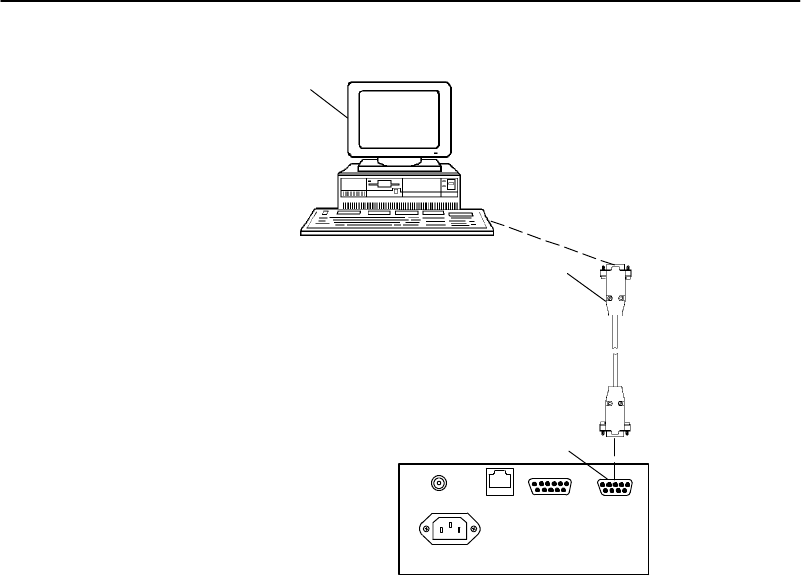
SECTION4"Configuration
6710 Access PointUser’sGuide 4-3
1.PCwithterminalemulation program
2.Cable:321-355-001 fora 25-pinPC COMport
or
Cable:226-106-001 fora 9-pinPC COMport
(standard null modemcable)
3.6710 Access PointDIAGport
2
Figure 4-1
LocalSession
3
10BASE210BASET
AC INPUT
AUIDIAG
100/240 VAC
1
1.Ensuretheterminalemulationprogramisinstalled
onthePC.
2.WithboththePCandaccess pointpoweredOFF,
connect thecommunicationcabletotheappropriate
PC COMport.

SECTION4"Configuration
4-46710 Access PointUser’sGuide
3.Connect the otherendofthecommunicationcableto
theDIAGportontheaccess point.TurnthePCon.
4.AfterthePCboots,start theterminalemulation
program.
5.Set theterminalemulationprogram’soptions
accordingtowhatyouwant todo:Access the
configurationmenus,oraccess theROM command
monitor.
Accessing theConfiguration
Menus
1.Set theterminalemulationparametersinyour
communications software.Ifyouareconfiguringthis
access pointforthefirst time,set theparametersto
theaccess point’sdefaultsettings:
9600,8N1,full duplex
Ifyou havealreadychangedthedefaultsettings,set
theparameterstothoseyousetinFLASHmode
throughtheconfigurationmenus.
2.Plugtheaccess pointintothe outlet.Thesemessages
appear:
QXS6700K<version> <date>
<Press anykeywithin5secondstoenter theROMmonitor>
ExecutingfileUSTART29.BINfromsegment<segmentnumber>
Quicklypress akeytoperformconfigurationbefore startup
Startingsystem
3.Toaccess theconfigurationmenus, waituntil yousee
themessage“Quicklypress akeytoperform
configurationbeforestartup.”Press anykeytoaccess
theconfigurationmenus.
4.See “ConfiguringtheAccess Point” onpage4-12.

SECTION4"Configuration
6710 Access PointUser’sGuide 4-5
Accessing theROMCommand
Monitor
1.Set theterminalemulationparametersinyour
communications software.Ifyouareconfiguringthis
access pointforthefirst time,set theparametersto
thedefaultsettingsforROMmode:
9600,8N1,full duplex
Ifyou havealreadychangedthedefaultsettings,set
theparameterstothoseyousetinROMmodethrough
theROM commandmonitor.
2.Plugtheaccess pointintothe outlet.Thesemessages
appear:
QXS6700K<version> <date>
<Press anykeywithin5secondstoenter theROMmonitor>
ExecutingfileUSTART29.BINfromsegment<segmentnumber>
Quicklypress akeytoperformconfigurationbefore startup
Startingsystem
3.Press anykeywithin5secondsofthefirstROM
message.
Notethatiftheaccess pointisinPower-UpQuiet
mode(versusPower-UpNormalmode,thedefault
setting),theROMmessagesdonotdisplay.More
informationaboutPower-UpQuiet(PQ)modeand
Power-UpNormal(PN)modestartsonpage5-27 in
Section5,“SoftwareDownload.”
4.See page5-22 inSection5,“SoftwareDownload,”for
informationabout theROM commandmonitor.
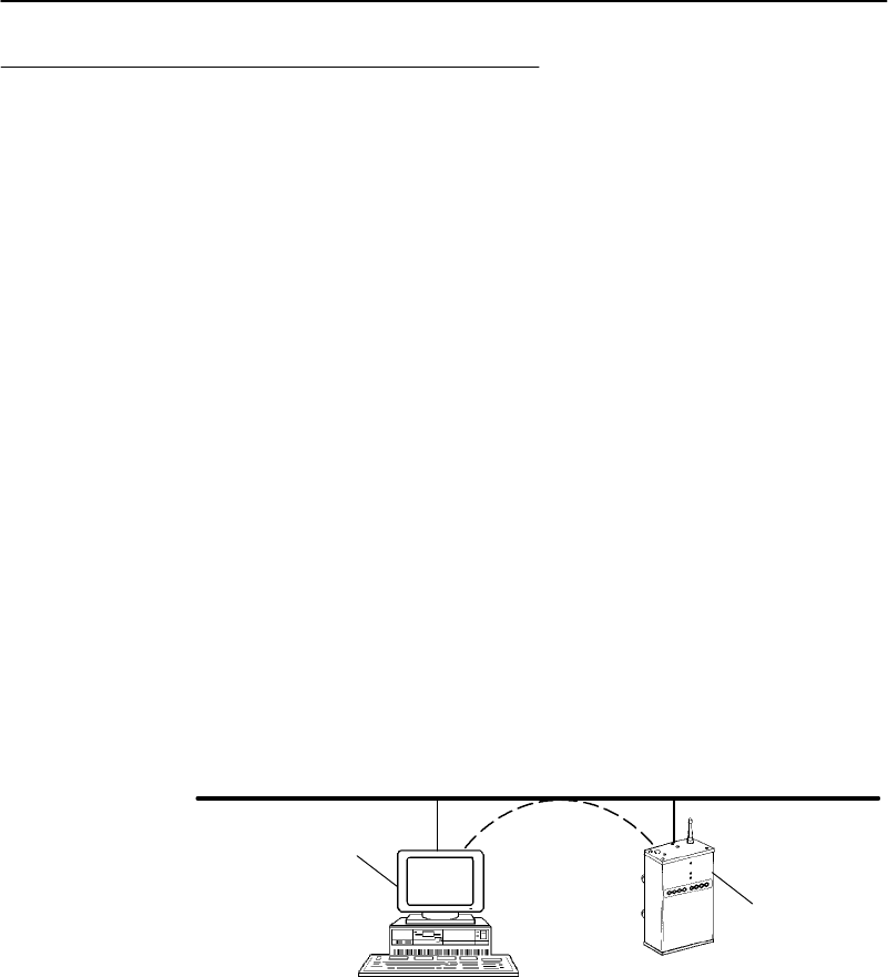
SECTION4"Configuration
4-66710 Access PointUser’sGuide
Creating aTelnetSession
Beforeyoucanconfiguretheaccess point throughTelnet,
youmustconnect theunit totheEthernetcable.(See
Section3,“Installation,”forhelp.)Youmustalsoperform
initialconfigurationthroughtheDIAGport to:
"SetanIPaddress orDHCPservername.Youshould
alsoconfigureasubnet maskandIProuteraddress.
"Set theEthernetcabletype.
"NOTE:The access pointincludesan autodetect featurethatsensesthe
Ethernetmediumif trafficispresent. If no trafficispresenton the
cable, the systemsoftware defaultsto 10BASE-T.For most
installations,itisrecommended thatyou explicitly set the Ethernet
type.
Theaccess point mustgothroughitsbootsequencebefore
youcancreateaTelnetsession.Ifyoureboot theunitwhile
inasession,thesessionterminates.Youcancreateanew
sessionaftertheunitreboots.
TocreateaTelnetsession,see Figure4-2 andtheprocedure
followingit.
1.PCorworkstation with TelnetVTemulator(TNVT)
2.6710 Access Point
Figure 4-2
TelnetSession
EthernetLAN Telnet
1
2

SECTION4"Configuration
6710 Access PointUser’sGuide 4-7
1.Ensuretheaccess pointisconnectedtotheEthernet
cable,andhasanassignedIPaddress andcabletype.
2.EnsurethePCorworkstation hasaninstalledand
configuredEthernetinterfacecard.
3.EnsuretheTelnetVTemulatorisinstalledonthePC
orworkstation.
4. OpenanewTelnetsessiononthePCorworkstation.
5.Entertheaccess point’sIPaddress inthehostname
orIPaddress field.
6.See “ConfiguringtheAccess Point” onpage4-12.
Defaultand SiteSettings
Theaccess pointisfactoryconfiguredwiththedefault
settingslistedinthefollowingcharts.Youmayneedto
changethedefaultstomatchtheway yoursystemis setup.
Youcanrecordyoursite’s settingsinthetablefor reference.
TCP/IP
OptionDefaultSiteSetting
IPAddress 0.0.0.0
IPSubnetMask255.255.255.0
IPRouter0.0.0.0
IP FrameTypeDIX
DHCPEnabled,ifIPAd-
dress iszero
DHCPServerNameNorandDHCPServer
AutoARPMinutes5

SECTION4"Configuration
4-86710 Access PointUser’sGuide
Security
OptionDefaultSiteSetting
PasswordCR52401
ServicePasswordEnabled
AdvancedPassword“” (emptystring)
Bridge
OptionDefaultSiteSetting
Serial Number(Read-only)
LanID0
[Root]
RootPriority1
[GlobalRadio]
UHFRfpThreshold
SetGloballyDisabled
Value70
UHF FragSize
SetGloballyDisabled
Value250
FalcFragSize
SetGloballyDisabled
Value250
AwakeTime
SetGloballyDisabled
Value0
[GlobalFlooding]
Inbound
MulticastPrimary
UnicastDisabled
OutboundtoSecondaries
MulticastDisabled
UnicastDisabled
OutboundtoStations
MulticastDisabled
UnicastDisabled

SECTION4"Configuration
6710 Access PointUser’sGuide 4-9
OptionSiteSettingDefault
[Ports]
Ethernetport:
Name omde
MAC Address (Uniquenumber)
StatusEnabled
HelloPeriod2seconds
[Ethernet]
OWL FrameTypeDIX
CableTypeAutoDetect
[StaticAddresses]00:00:00:00:00:00
[NormalRXFilter]
[FrameTypes]
ActionPass
ScopeUnlisted
[SubTypes1]
ActionPass
SubType(Various)
Scope(Various)
[SubTypes2]
ActionPass
SubTypeDIX--IP--TCP--Port
Scope00 00
[AdvancedRXFilter]
[Expressions]
ExprSeq 0
Offset0
OpEQ
ValueId0
ActionAnd
[Values]
Value0
[Bridging]
BridgePriority1
StatusEnabled
FloodRegisterDisabled

SECTION4"Configuration
4-10 6710 Access PointUser’sGuide
OptionSiteSettingDefault
WLIFradioport:
Name omdpxma
MAC Address (Uniquenumber)
StatusEnabled
HelloPeriod2seconds
[WLIF]
SecurityIdNORANDOWL
NodeTypeMaster
[MasterParms]
Channel1
Subchannel1
Wireless HopsDisabled
MAC ConfigDefault
[ManualMAC Parms]
HopPeriod200 ms
BeaconFrequency2
DeferralSlotDefault
Fairness SlotDefault
FragmentSize310
TransmitModeAUTO
NormAckRetry255
FragAckRetry255
NormQFSKRetry255
FragQFSKRetry255
900 MHz radioport:
Name omdflca
MAC Address (Uniquenumber)
StatusEnabled
HelloPeriod1second
[Falcon]
FileNamefalcon_d.29k
Mode--Channel(Firstmodeinlist)
ARPServer ModeDisabled

SECTION4"Configuration
6710 Access PointUser’sGuide 4-11
OptionSiteSettingDefault
S-UHFradioport:
Name omduhfb
MAC Address (Uniquenumber)
StatusEnabled
HelloPeriod2seconds
[UHF]
FileNamesynuhf_d.29k
Call Sign“” (emptystring)
Frequency(Firstfrequencyinlist)
Master ModeDisabled
AttachPriorityHigh
OWL/IPport:
Name omdip
MAC Address (Uniquenumber)
StatusEnabled
HelloPeriod2seconds
[OWL/IP]
ModeListen
[IPAddresses]
TypeUnicast
Address (None)
[TXFilter]
[FrameTypes]
ActionPass
ScopeUnlisted
[SubTypes1]
ActionPass
SubType(Various subtypes)
Scope(Various settings)
[SubTypes2]
ActionPass
SubTypeDIX--IP--TCP--Port
Scope00 00

SECTION4"Configuration
4-12 6710 Access PointUser’sGuide
Configuring theAccess Point
WhenyoucreatealocalDIAGportor remoteTelnetsession
withtheaccess point,theconfigurationprogram’spassword
screenappears:
Configuration of Access Point
Copyright (c) 1995-1997 Norand Corporation. All rights reserved.
Portions copyright Epilogue Technology Corporation 1988-1995.
All rights reserved
IP: 0.0.0.0
Serial: (Unique 10-digit number.)
Password:
"NOTE:Adifferentscreen appearswhen you createasession through a
Web browser.See page 4-88 forinformation aboutWeb browser
sessions.
ThepasswordscreenshowsthecurrentsettingsfortheIP
address andserialnumber.Italsoshowsthepromptfor
thetop-levelpassword.Enterthepassword(case
insensitive)todisplaytheMainMenu.Thedefault
passwordisCR52401.
MainMenu
Afteryouenterthetop-levelpassword,theMainMenu
appears:

SECTION4"Configuration
6710 Access PointUser’sGuide 4-13
Loading configuration from EEPROM
Command Description
File File system menu
View View/modify the configuration
Clear Set the configuration to default values
Read Read the configuration from EEPROM
Write Write the configuration to EEPROM
Reboot Restart using last written configuration
Exit Disconnect
? Display this help
>
Themenu liststhecommandsyoucan usetodovarious
tasks,describedonthefollowingpages.Thescreenalso
displaysthecommand prompt(>).At theprompt,typethe
name ofthecommandyouwant toperformand press
[Enter].(Commandsarecaseinsensitive.)TheMainMenu
redisplayswhenyouenteraninvalidcommand.
Thefollowingchartdescribeshowtousethecommands.
UseTo
FileListfilesystemcommandsand descriptions.
Section5,“SoftwareDownload,”describesthe
commandsandfilesystem methodology.
ViewViewormodifyconfigurationprogramsettings.
See “UsingtheViewCommand”onpage4-14.
ClearReset theaccess point’sconfigurationtothefacto-
ry-setdefaultsettings, whichstartonpage4-7.
ReadLoadthemostrecentconfigurationfrom
EEPROM.Theconfigurationthatwaswrittento
EEPROMsincetheaccess pointwaslast
rebootedbecomesthenewconfiguration.

SECTION4"Configuration
4-14 6710 Access PointUser’sGuide
UseTo
Read
(Continued)Theaccess point’sconfigurationis storedin
EEPROM.Youreprogram theEEPROM
wheneveryouchangetheconfiguration, write
(save)thenewconfigurationtoEEPROM,and
reboot theaccess point.
WriteWrite(save)anewconfigurationtoEEPROM.
Thiscommandoverwritesthepreviousconfigura-
tion.Youmustwritethenewconfiguration
toEEPROMandreboot theaccess pointfor
anychangestotake effect.
RebootReboot theaccess point.Youmustreboot theunit
foranychangesyoumadetotheconfigurationto
take effect.
ExitQuit theconfigurationprogram.Ifyouexitanew
configurationwithoutwritingit toEEPROM,any
changesyoumadearenotsaved.
?Displayonlinehelpforacommand,option,or
setting.
Using theViewCommand
Toviewormodifyconfigurationprogramsettings,type
Viewat thecommand prompt.TheMainOptionsMenu
appears:
[Tcpip]
[Bridge]
[Security]
Thefollowingchartdescribeshowtousethe options.

SECTION4"Configuration
6710 Access PointUser’sGuide 4-15
UseTo
[Tcpip]
Page4-16 Setoptionsnecessaryfor communicationswith
thisaccess point.The optionsapplytoall
TCP/IPports.Telnet,SNMP,andHTTP
communicationsaresupported.
[Bridge]
Page4-23 Controlthebridgingofmessagesamongthe
radioandEthernetportsforthisaccess point.
Settingstocontrol interactionwithotheraccess
pointsarealsounderthe[Bridge]option.
[Security]
Page4-86 Set theconfigurationprogram’stop-level
passwordandothersecuritypasswords.
Thescreensinthis sectionshowthe options’default
settings.Somesettings(suchastheserialnumber)are
uniqueto eachaccess point. Othersettings(suchascertain
radioconfigurations)areautomaticallysetandyoucannot
changethem.This sectionidentifiesthesettingsyou
cannotchangeas“read-only.”
ThefollowingchartshowshowtonavigatetheView
command’smenusandeditdata.
Press To
[-]or[--] Scroll upthroughitemsinalist.
[¯],[+],[=],or[Tab]Scroll downthroughitemsinalist.
[®],[Enter],or[Spacebar]Displayanoption’s settingsor
promptafteryou highlight the
option.Alsousethesekeysto
select thedesiredsetting.
[¬],[Esc],or[Backspace]Exitamenu orprompt.
[Esc]Cancelediting.
[Enter]Complete editing.

SECTION4"Configuration
4-16 6710 Access PointUser’sGuide
TCP/IPOptions
Use[Tcpip]tosetoptionsnecessaryfor communications
withthisaccess point,suchasIPaddresses.Addressesare
requiredfor remotesetuporSNMPnetworkmanagement.
Optionsare:
IP Address 0.0.0.0
IP Subnet Mask 255.255.255.0
IP Router 0.0.0.0
IP Frame Type <DIX>
DHCP <Enabled, if IP address is zero>
DHCP Server Name “Norand DHCP Server”
Auto ARP Minutes 5
IPAddress
IPAddress istheuniqueaddress locallyassignedtothis
access point.Thepromptis:
Range is:
4 nums 0..255
Thedefaultis0.0.0.0, whichdisablestheabilitytouse
TCP/IP.Followingaresuggestionsforsettingtheaddress:
"Ifyouareinstallingthisaccess pointonanexisting
Ethernetsegment,youshouldallocatetheIPaddress
from thesamepoolasthe existingcomputersonthe
segment.
"Ifyouareinstallingthisaccess pointonanew
Ethernetsegment thatisnotgoingtoconnect tothe
Internet,tryusingthisClass Baddress:
172.16.h.h

SECTION4"Configuration
6710 Access PointUser’sGuide 4-17
Thehostnumberis“h.h.”ThisClass Bnetwork
address isreservedbythenumberingauthorityfora
company’sinternaluse.IftheClass Baddress
appearsontheInternet,routersdropthedata.
Notethefollowing:
"IftheIPaddress is0.0.0.0and DHCPis set to
“Enabled,ifIPaddress iszero,” thisIPaddress is
obtainedthroughDHCP.
"IfDHCPis set toEnabled, DHCPisusedto obtainthe
IPaddress.
"IftheIPaddress is0.0.0.0and DHCPisdisabled,
TCP/IPaccess tothisaccess pointisdisabled.
AdiscussionofDHCPstartsonpage4-19.
IP SubnetMask
IPsubnetspartitiontrafficandareconnectedbyrouters.
Thesubnet maskindicateshowmanybitsoftheIPaddress
representanetworknumberandhowmanyindicateahost
number.Thepromptis:
Range is:
4 nums 0..255
Thedefaultis255.255.255.0.Followingaresuggestionsfor
settingthesubnet mask:
"Ifyouareinstallingthisaccess pointonanexisting
Ethernetsegment,thesubnet maskshouldmatchthe
other computersonthesegment.
"Ifyouareusingthe172.16.h.haddress suggestedfor
IPAddress,youmaywant touseasubnet maskof
255.255.248.0.Thismaskprovidesthenetwork
172.16 with30 subnetsof2046 computerseach.
TheIPaddress breakdownis:

SECTION4"Configuration
4-18 6710 Access PointUser’sGuide
"16 bitsofnetworkaddress.
"5 bitsofsubnetaddress. Donotuseall 0’sorall
1’s.
"11 bitsofhostaddress. Donotuseall 0’sorall
1’s.
ThefollowingchartlistsIPaddresseswhenthesubmaskis
255.255.248.0.
SubnetFirstAddress LastAddress
1 172.16.8.1 172.16.15.254
2 172.16.16.1 172.16.23.254
3 172.16.24.1 172.16.31.254
.
.
.
30 172.16.240.1 172.16.247.254
IfyouareusingDHCPto obtainanIPsubnet maskforthis
access point,thesubnet maskobtainedfromDHCP
overridesthesettingfortheIPSubnetMaskoption.
IPRouter
"NOTE:The IPaddress of the routerisrequired onlyif thisaccess pointwill
communicatewith deviceson the otherside of the router.
IPRouteridentifiesthedefaultrouterusedtoforward data
framestoaddressesonanothersubnet.Thepromptis:
Range is:
4 nums 0..255
Thedefaultis0.0.0.0, whichdisablestheabilityto
exchangeTCP/IPtrafficwithanothersubnetornetwork.

SECTION4"Configuration
6710 Access PointUser’sGuide 4-19
Arouterthatconnects subnet1tosubnet2mighthavethe
address 172.16.8.1onsubnet1 and172.16.16.1onsubnet2.
AhostwithIPaddress 172.16.16.5wouldspecifyanIP
routeraddress of172.16.16.1toreach host172.16.8.10.
IProutersareusuallyconfiguredsoacomputeronlyneeds
toknowonerouter’saddress.Thisistrue evenifseveral
routersonthesegmentconnect toseveralothersegments.
IfyouareusingDHCPto obtainanIProuteraddress,and
theDHCPserverspecifiesadefaultIProuter,theDHCP
serverspecificationoverridesthesettingforIPRouter.
IPFrameType
IP FrameTypesetsthetype of framecontainingIPtraffic:
DIX
802.3
SettingDescription
DIX(default)SetsEthernet typetoDIX(Ethernet2.0) forIP
frames.
802.3SetsEthernet typeto802.3withaSNAPheader
forIPframes.Select802.3ifothernetwork
computersuseSNAPencapsulationforIP
frames.
DHCP
DHCPprovidesawayforthisaccess point(theclient)to
obtainIPaddressesfromaDHCPserveronthenetwork.
Settingsare:
Enabled
Enabled, if IP address is zero
Disabled

SECTION4"Configuration
4-20 6710 Access PointUser’sGuide
SettingDescription
EnabledDHCPalwaysobtainsIPaddressesforthe
access point,subnet mask,and(optional)
defaultrouterwhentheaccess pointreboots.
Italso obtainsthelease expirationtime.
Enabled,ifIP
address iszero
(default)
IfIPAddress is0.0.0.0, DHCPobtainsIP
addressesfortheaccess point,subnet mask,
and(optional)defaultrouter.Italso obtains
thelease expirationtime.Theaccess point
ignoresotherDHCPconfigurationoptions.
DisabledDisablesDHCP.Youmust manuallyset theIP
addressesbeforetheTCP/IPstackisenabled.
"NOTE:If you are using OWL/IPtunneling,you should notuseDHCPto
allocateIPaddressestosuper rootcandidatesordesignated bridges
unless a permanentleaseisused,and the access pointisrebooted
aftergetting an address. OWL/IPoptions starton page 4-79.
Theaccess pointrespondsonlytoaddress offersfrom
DHCPorBootpservers.Ineither casetheserveris
specifiedintheDHCPservernamefield.
DHCP ServerName
ThepromptfortheDHCPservernameis:
Range is:
31 chars
Theaccess pointrespondsonlytothenamedserver.The
defaultservernameis“NorandDHCPServer.”Thisname
preventstheaccess pointfrominadvertentlyobtainingan
IPconfigurationfromexistingserversonthenetwork.
IftheDHCPservernameisconfiguredwithanull string
(“”),theaccess pointrespondsto offersfromanyserver.

SECTION4"Configuration
6710 Access PointUser’sGuide 4-21
Theclass identifierstringfortheaccess pointis“Norand
Access Point.”Serversusethis stringtoidentifytheaccess
point.
BootpOperation
Theaccess pointcanalsoacceptaddressesfromaBootp
serveridentifiedintheDHCPservernamefield.An
address offerfromaBootpserveristreatedasifitwerean
infiniteleasefromaDHCPserver.
Networks WithDHCPand BootpServers
IftheDHCPservernameisconfiguredas“”,theaccess
pointrespondsto eitherDHCPorBootpservers.The
access pointgivespreferencetoDHCPoffers.IfaBootp
replyarrivesat theaccess pointbeforeanyDHCPoffersare
received,theaccess pointwaitsanadditional4secondsfor
aDHCPofferbeforeresponding.IfaDHCPofferis
receivedwithinthe4-second period,theBootpreplyis
ignoredandtheDHCPofferisaccepted.
Handshaking
Whentheaccess pointrespondstoaDHCPorBootpserver,
itbroadcastsasingleARPrequest totheaddress offered.If
noARPresponseisreceivedwithin3seconds,theaccess
pointassumestheIPaddress isuniqueandcompletesthe
negotiationforthataddress.IfanARPreplyisreceived
beforethetimeout,theaccess pointassumestheaddress is
aduplicateand declinesthe offer.
InfiniteLeases
ADHCPservermaybeconfiguredtograntaninfinitelease
totheaccess point.A Bootpgrantisalwaystreatedasan
infinitelease.Theaccess pointstorestheIPaddress,
subnet mask,and defaultrouterintheEEPROM
configurationregisterand disablesDHCP.Thesesettings
aremaintainediftheaccess pointispoweredoff or rebooted
throughtheROM commandmonitor.TorestoreDHCP
clientoperation,reconfiguretheIPaddress to0.0.0.0.

SECTION4"Configuration
4-22 6710 Access PointUser’sGuide
"NOTE:DHCPisdocumented inRFCs1533,1534,and 1541.Bootpis
documented inRFC951.
AutoARPMinutes
Theaccess pointperiodicallysendsan unsolicitedARP
responsesorouterscan updatetheir routingtables.The
response enablesanetworkmanagementplatform tolearn
about theaccess pointonthenetworkbyqueryingrouters.
AutoARPMinutesisthenumberofminutesbetween
periodicARPrequests.Thepromptis:
Range is:
0..120
Thedefaultis5minutes.Asettingof0disablesAutoARP
Minutes.
Ifthedefaultrouter’saddress is0,theARPrequestis sent
totheIPaddress ofthisaccess point.Without theAuto
ARPMinutesoption,anaccess point mightnotuseitsIP
address forextended periodsoftimeandexpirefrom the
router’sARPtable.
AutoARPMinutesenhancesthediscoveryofthenetwork
architecturebynetworkmanagement tools,suchas
OpenViewbyHewlett-Packard.Thenetworkmanagement
toolqueriesIProuterARPtablestolocatetheactiveIP
addressesforthesubnetIPaddressesforaccess points
shouldnotbeallowedto expire.Thenetworkmanagement
programwouldthen needtopingall potentialaddresseson
asubnet tolocateactiveIPaddresses,or requiretheuserto
enteralist.

SECTION4"Configuration
6710 Access PointUser’sGuide 4-23
BridgeOptions
Use[Bridge]toconfigure optionsthatdefinethebridging
topology ofthe openwireless LAN. Optionsare:
Serial Number “(Unique 10-digit number.)”
Lan ID 0
[Root]
[Ports]
ARP Server Mode <Disabled>
SerialNumber
Serial Numberisaread-onlysettingthatdisplaysthis
access point’sunique10-digitserialnumber, which
identifiesthisunitonthenetwork.
LanID
TheLANID(alsocalleddomain)isanumberthatlogically
isolatesadjacentbutindependentopenwireless LANs.The
promptis:
Range is:
0..254
Followingareranges:
"900 MHzandS-UHFradios:0(default)to254.
"WLIFradio:0to15.
"NOTE:For mixed systems containing WLIFradios,you mustuse LANID0
to 15.

SECTION4"Configuration
4-24 6710 Access PointUser’sGuide
Youshouldchangethedefaultof0toanothernumberto
avoidapotentialconflictwithanadjacentnetwork.All
access pointsandwireless stationsinthesamenetwork
musthavethesameLANID.
"NOTE:See page 4-87 forinformation aboutcombining WLIF,900 MHz,and
S-UHFradiosinacommon networkbyfollowing basicguidelinesfor
LANIDand controllersetup.
[Root]
[Root]optionsapplytoaccess pointsconfiguredto operate
asthesuper root.Theyshouldbeset tothesamesettings
inall access pointswithanonzerorootpriorityconfigured.
Optionsare:
Root Priority
[Global Radio]
[Global Flooding]
RootPriority
RootPrioritydetermineswhichaccess pointsarecandidates
tobecomethesuper rootnode onthedistributionLAN(also
calledprimaryLAN).Thepromptis:
Range is:
0..7
Thedefaultis1.
SuperRootCandidates
Access pointsassignedarootprioritybetween1 and7 are
candidatestobecomethesuper root.Access points
assignedarootpriorityof0 areprohibitedfrombecoming
thesuper root.

SECTION4"Configuration
6710 Access PointUser’sGuide 4-25
SuperRootSelection
Theaccess pointwiththehighestassignedrootpriority
becomesthesuper rootwheneveritispoweredonand
active.Ifthecurrentsuper rootgoesoffline,theremaining
candidatesnegotiatetodeterminewhichonebecomesthe
newsuper root.Thisnormallytakesabout1minute.
Thesuper rootisalwaystheaccess pointwiththehighest
rootpriority(otherthan0).Iftwo ormoreaccess points
havethesamerootpriority,theunitwiththehighest
Ethernetaddress becomesthesuper root.
SuperRootRedundancy
Forredundancy,two orthree access points shouldhavea
nonzerorootpriority.All otheraccess points shouldhavea
rootpriorityof0.(Redundancyistheabilityofanother
access point totake overifthesuper rootgoesoffline.)
Youshould dothefollowing:
"Configure oneaccess pointasaprimarysuper root
(withthehighestrootpriority).
"Configure one ortwoaccess pointsas“fallback”super
roots(withlowerpriority).
"Configureremainingaccess pointswitharootpriority
of0.
[GlobalRadio]
"NOTE:Usethe same[Global Radio]settingsin all super rootcandidates.
[GlobalRadio]distributesnetwork-wideconfiguration
parameters.Settingsinthesuper rootaredistributed
throughout thenetwork. Optionsare:
Set Globally Value
UHF Rfp Threshold <Disabled> 70
UHF Frag Size <Disabled> 250
Falcon Frag Size <Disabled> 250
Awake Time <Disabled> 0

SECTION4"Configuration
4-26 6710 Access PointUser’sGuide
Theprevious samplescreenshowsthe options’default
settings, whichare optimumformostinstallations.Itis
recommendedthatyou notchangethedefaults.
OptionDescription
UHFRfpThresholdThisoptionadjuststheS-UHFprotocol
characteristicsforsmallerdataframes.
Therecommendedsettinginmostcasesis
Disabled.Forinstallationsthatprimari-
lysendverysmall frames,Enabledat the
defaultvalue of70 mayimprovenetwork
responsetime.
UHF FragSizeFor reliabletransmission,largeframes
maybefragmentedorsplitintoseveral
smallerframes.Thereceiver reassembles
thefragmentsintoacompleteframe.The
defaultis250.
FalconFragSizeFor reliabletransmission,largeframes
maybefragmentedorsplitintoseveral
smallerframes.Thereceiver reassembles
thefragmentsintoacompleteframe.The
defaultis250.
AwakeTime
(Does notapplyto
WLIFradio.)
Thisoptionestablishesanawaketime
afterastationtransmits.Portable
stationsdonotenterapowermanaged
stateforthistimeperiod.Theaccess
point maydeliveraresponsewithout
usingthependingmessagedelivery
mechanismduringtheawaketime.
Thetimeis specifiedintenthsofseconds.
WhenawaketimeisDisabled(the
default),eachstation usesitsowndefault
(2secondsfor900 MHzorS-UHF
stations).Longerawaketimesmay
reducestationbatterylife.

SECTION4"Configuration
6710 Access PointUser’sGuide 4-27
Each[GlobalRadio]option hasthefollowingsettings:
Set Globally <Disabled>
Value 0
SetGlobally
Thevalueforall radiosinthesystemis specifiedaccording
tohowSetGloballyisconfigured.
SettingDescription
EnabledIfthisaccess pointisthesuper root,itsetsthe
valueforall stationsandaccess pointsinthe
network.This settinghasno effectinaccess
pointsotherthanthesuper root.
Disabled
(default)Thesuper rootdoesnotdistributeglobal
parameters.All radiosinthenetworkuselocal
settingsordefaults.
Value
Followingarerangesand defaultsfortheValue option.
ValueRangeDefault
UHFRfpThreshold0--250 octets70
UHF FragSize0--250 octets250
FalconFragSize0--250 octets250
AwakeTime0--255 (tenthsofseconds)0

SECTION4"Configuration
4-28 6710 Access PointUser’sGuide
[GlobalFlooding]
"NOTE:Usethe same[GlobalFlooding]settingsin all super rootcandidates.
Use[GlobalFlooding]tosetsystem-widefloodingoptions.
Thesettingsaresent throughout thenetworkwhenandif
thisaccess pointbecomesthesuper root. Optionsare:
Multicast Unicast
Inbound <Primary> <Disabled>
Outbound to Secondaries <Disabled> <Disabled>
Outbound to Stations <Disabled> <Disabled>
Anaccess pointnormallyforwardsframesonlyto
destinationaddressesithaslearnedandstoredinthe
forwardingdatabase.Framesareforwardedonlyonthe
port thatprovidestheshortestpathtothedestination
address.Theaccess pointcanbeconfiguredtofloodframes
onone ormoreportswhenthedestinationaddress is
unknown.
Globalfloodingoptionsallowfordifferentflooding
configurationsto optimizeperformance.Settingsinthe
super rootaredistributedtoall otheraccess points.
AframefloodedtowardthedistributionLAN(LANsegment
containingthesuper root)isinbound.Aframeflooded
awayfrom thedistributionLAN isoutbound.Aspecial
case ofoutboundisoutbound tosecondaryLANs.
"NOTE:AFlooding Level Checkliststartson page 4-31.
Inbound
Floodingmaybeconfiguredseparatelyforunicast(single
physicaladdress)andmulticast(groupaddress) frame
types.Manynetworkprotocolsusemulticast messagesfor
establishingandmaintainingconnections,anduseunicast
messagesfordataexchange.

SECTION4"Configuration
6710 Access PointUser’sGuide 4-29
Inboundoptionsare:
Multicast <Primary>
Unicast <Disabled>
MulticastandUnicastoptionshavethefollowingsettings:
Enabled
Primary
Disabled
SettingDescription
EnabledAccess pointfloodstoall ports,similartoa
conventionalbridge.
Primary
(Multicastdefault)Framesarefloodedinboundonly.This
settingisuseful inmanywireless installa-
tionswherethesuper root,servers,or
gatewaysforwireless stationsare onthe
sameEthernetsegment.
Disabled
(Unicastdefault)Framesarenotflooded.Usethis setting
onlyiftheOutboundtoSecondariesoption
isalsoset toDisabled.
Outbound toSecondaries
OutboundtoSecondariesfloodsframeswith unknown
destinationstosecondaryLANsegments.Settingsare:
Enabled
Registered
Disabled

SECTION4"Configuration
4-30 6710 Access PointUser’sGuide
SettingDescription
EnabledAll designatedbridgesfloodtosecondary
LANs.This settingallowsthesuper root to
controlfloodingforall access points serving
asdesignatedbridgesforsecondaryLANs
(see page4-57).
RegisteredDesignatedbridgesfloodaccordingtotheir
individualfloodregistersettings.This set-
tingallowsindividualdesignatedbridgesto
beconfiguredseparately.
Disabled
(Multicastand
Unicastdefault)
Floodingisdisabledinall designated
bridges.This settingallowsthesuper root to
controlfloodingforall access points serving
asdesignatedbridgesforsecondaryLANs
(see page4-57).This settingshouldbeused
onlyifInboundfloodingisDisabled.
Outbound toStations
OutboundtoStationsappliesonlytoaccess pointswiththe
WLIFradio option.Settingsare:
Enabled
Disabled
SettingDescription
EnabledFramesareflooded.
Disabled
(Multicastand
Unicastdefault)
Framesarenotflooded.

SECTION4"Configuration
6710 Access PointUser’sGuide 4-31
Flooding LevelChecklist
Youcan usethefollowinglistofquestionstodeterminethe
requiredfloodinglevelsfortheInboundandOutboundto
Secondariesoptions.Thelistis structuredsothatyou
shouldskiplaterquestionsas soonasyoudetermine
theappropriatefloodlevelsettings.
Ifyouransweris“Idonotknow,”gotothenextquestion.If
youcannotdeterminetheappropriatefloodinglevels,use
thehigher(multicast) floodinglevels.
"NOTE:If extensiveflooding isenabled,itwill be moreimportant toset
Ethernet filterstoreduce unnecessarytrafficinthe radio network. In
general, the need forfiltersincreaseswiththe amountof trafficon
the distribution LANand the flooding levels.Filtering startson page
4-43.
1.Isthe openwireless LANusedonlywithNORANDR
emulationterminals?
AnswerSettings
YesInbound/Unicast/Disabled
Inbound/Multicast/Enabled
OutboundtoSecondaries/Unicast/Disabled
OutboundtoSecondaries/Multicast/Disabled
Comments:
UnicastfloodingisnotrequiredtosupportNORAND
terminalemulationbecausetheNORANDtransport
layer(usedforterminalemulation)periodically
generatestraffic.Inboundmulticastfloodingis
required. Outboundmulticastfloodingisnotrequired
becauseNORANDterminalemulationstationsdonot
needtoreceivemulticastframes.

SECTION4"Configuration
4-32 6710 Access PointUser’sGuide
2. Doesthenetworkcontainonly900 MHzorS-UHF
access points?
AnswerSettings
YesInbound/Unicast/Disabled
OutboundtoSecondaries/Unicast/Disabled
Comments:
Unicastfloodingisnever requiredfor900 MHzor
S-UHFaccess points,sincestations supportingthese
mediaoptionsestablishreliableconnectionsasthey
roambetweenaccess points.Thecorrectportfor
S-UHFor900 MHzstationsisalwaysknown.
3. Doall nodesintheradionetworkroutinelytransmita
frameatleastonce every4minutes?
AnswerSettings
YesInbound/Unicast/Disabled
OutboundtoSecondaries/Unicast/Disabled
4. Doanynodesintheradionetworkneedtoreceive
multicastorbroadcast messages?
AnswerSettings
NoInbound/Multicast/Enabled
OutboundtoSecondaries/Multicast/Disabled
Note:TCP/IPnodesmustreceive broadcastARPframes.
Comments:
Thedestinationofamulticastframeisneverknown.
TheDisabledsettingshouldbeusedforanynetwork
wherestationsdonotneedtoreceivemulticast
frames.TheDisabledsettingcanbeusedfor
secondaryLANsthatonlyneedtoreceiveARPframes.
WhenWLIFwireless stationsmustreceivemulticast
frames,setOutboundtoStationstoEnabled.

SECTION4"Configuration
6710 Access PointUser’sGuide 4-33
5. Donodesintheradionetworkcommunicatewith
othernodesintheradionetwork?
AnswerSettings
YesInbound/Unicast/Enabled
Inbound/Multicast/Enabled
NoInbound/Unicast/Primary
Inbound/Multicast/Primary
OutboundtoSecondaries/Unicast/Registered
OutboundtoSecondaries/Multicast/Registered
Comments:
TheEnabledsettingsfacilitatepeer-to-peer
applications, wherenodesinthe openwireless LAN
communicatewitheachother.
Ingeneral,thePrimaryandRegisteredsettingsare
designedfor clientorterminalapplicationswhere
nodesinthe openwireless LANcommunicatewith
servernodesonthedistributionLAN.
6. Doradio-equippedwireless station nodes(openor
non-wireless LAN)needtoreceivemulticastor
broadcastframes?
AnswerSetting
YesOutboundtoStations/Multicast/Enabled

SECTION4"Configuration
4-34 6710 Access PointUser’sGuide
7. DoestheradionetworkcontainWLIFnodesthatdo
notperiodically generatetraffic?
AnswerSetting
YesInbound/Unicast/Primary
OutboundtoSecondaries/Unicast/Registered*
or
Inbound/Unicast/Enabled**
*SupportcommunicationswithadistributionLAN.
** Supportsgeneralpeer-to-peer communications.
"NOTE:WLIFnodesusing NORAND terminalemulation periodically
generatetraffic,and do notrequireflooding.
Comments:
Youmayneedto enableunicastfloodingiftheradio
networkcontainsWLIFterminalnodesornodesona
secondaryEthernetLANthatdonotperiodically
generatetraffic. Occasionaltrafficisneededto
maintaininformationintheforwardingdatabase.
Youcanalsodothefollowing:
"UsetheOutboundtoSecondaries/Unicast/
EnabledsettingtoforceunicastfloodingtoWLIF
nodes.
"UsetheInbound/Unicast/PrimaryorOutbound
toSecondaries/Unicast/Registeredsettingin
combinationwiththeFloodRegister/Unicast
settingforselectedsecondaryEthernetLANs.
Thesesettingsavoidnetwork-wideuniversal
floodingifnodesthatdonotperiodically generate
trafficarerestrictedtothosesecondaryEthernet
LANs.

SECTION4"Configuration
6710 Access PointUser’sGuide 4-35
8. DoestheradionetworkcontainasecondaryEthernet
LAN(s)withconnectednodesthatdonotperiodically
generatetraffic?
AnswerSetting
YesOutboundtoSecondaries/Unicast/Enabled
Alternatively,youcanconfigurepermanent
addressesintheStaticAddress Table(page4-42).
9. DoestheradionetworkcontainasecondaryEthernet
LAN(s)withconnectednodesthat mustreceive
multicastorbroadcastframes?
AnswerSetting
YesInbound/Multicast/Primary
OutboundtoSecondaries/Multicast/Registered
or
Inbound/Multicast/Enabled
OutboundtoSecondaries/Multicast/Registered
Comments:
"Youcan usethesettingslistedintheabovechart
incombinationwithaFloodRegistersettingof
MulticastforselectedsecondaryEthernetLANs,
ifnodesintheradionetworkthat mustreceive
broadcastormulticastframesarerestrictedto
thoseLANs.
"YoushouldusetheOutboundto
Stations/Enabledsettingifwireless stations
mustreceivemulticastframes.Forexample,
TCP/IPwireless stationsmayneedtoreceive
broadcastARPrequests.
"Youcan useEthernetfilterstoreducemulticast
floodingforanyInboundorOutboundto
Secondaries settingotherthanDisabled.

SECTION4"Configuration
4-36 6710 Access PointUser’sGuide
S-UHF Flooding Level
Because ofitslowbandwidth,S-UHFisvulnerableto
excess trafficfrombusybackbones.Therecommended
settingsforS-UHFisInbound/Disabledand Outboundto
Secondaries/Disabled(forthemulticastandunicast
options).Thesesettingspreventexcessivetrafficfrom
beingforwardedontotheRFmedium.
Flood Register
Youcan usetheInboundoptionandOutboundto
SecondariesoptionincombinationwiththeFloodRegister
settingfortheEthernetport.Youcanconfigurethe
networksothatunicastormulticastframesareflooded
onlytosecondaryEthernetLANsthathaveunicastor
multicastflooding(orboth)enabled.Unicastandmulticast
floodingoptionsforsecondaryEthernetLANs startonpage
4-59.
ARP ServerMode
ARPServer Modecanconvert multicastARPrequeststo
unicastARPrequestsforstationsintheforwarding
database.ARPServer Modecansignificantlyimprove
wireless networkperformanceinbusyIPnetworks.
Settingsare:
Disabled
No Flooding
Delay Flooding
Normal Flooding
WhenARPServer Modeisenabled,theIPaddressesare
includedintheforwardingdatabase entryforthestation.
TheARPserverlearnstheIPaddressesofwireless stations
bymonitoringARPpackets.Additionally,somestations
mayhavethecapabilityofexplicitlyregisteringIP
addresseswiththeARPserver.

SECTION4"Configuration
6710 Access PointUser’sGuide 4-37
SettingDescription
Disabled
(default)NospecialactionistakenwhenanARPis
received.MulticastARPrequestsare
subject totheEthernetfiltersandtheflood-
ingsettings.TheDisabledsettingisuseful
whenasystemhasnoIPradiotrafficorhas
stationsthatdonotregisterIPaddresses.
NoFloodingARPserver convertsARPsfrom multicast to
theunicastaddress ofthedestinationsta-
tion.NoFloodingisthemostefficientcon-
figuration,sincemulticastARPsarenever
forwarded.Use ofthis settingrequires sta-
tionstoregisterIPaddresseswiththeaccess
point.UseNoFloodingorDisabledifwire-
less stationsdonotneedtorespondtoARPs.
DelayFloodingARPserver convertsARPsfrom multicast to
theunicastaddress ofthedestinationsta-
tion.Ifthedestinationaddress isunknown,
theinitialARPrequestisnotforwarded.If
therequestingdeviceretriestheARP
request,secondandsubsequentARPre-
questsareforwarded.ARPrequestsfrom
wireless stationsarefloodedinbound.
DelayFloodingisthepreferredoptionwhen
wireless stations shouldrespondtoARPs,
butarenotcapable ofregisteringtheirIP
addresseswiththeaccess point.
NormalFloodingARPserver convertsARPsfrom multicast to
theunicastaddress ofdestinationstation.If
thedestinationaddress isunknown,the
ARPrequestisfloodedaccordingtothemul-
ticastfloodlevelsettings.ARPrequests
fromwireless stationsarefloodedinbound.
NormalFloodingisusefulwhenwireless
stationsneedtorespondtoARPrequests,
butarenotcapable ofregisteringIPaddress-
eswiththeaccess point.NormalFlooding
sendsmoreunnecessaryARPsoverwireless
linksthendelayflooding.NormalFlooding
doesnotintroduce occasionaldelaysinARP
responsesasDelayFloodingdoes.

SECTION4"Configuration
4-38 6710 Access PointUser’sGuide
[Ports]
Use[Ports]todefine optionsfortheaccess point’sEthernet
port,radioports,andOWL/IP(IPtunneling)port.The
followingsamplescreenshowsall theports.
Name MAC Address Status Hello Period
1 “omde” 00:00:00:00:00:00 <Enabled> <2 Seconds>
2 “omdpxma” 00:00:00:00:00:00 <Enabled> <2 Seconds>
3 “omdflca” 09:46:19:01:0a:02 <Enabled> <1 Second>
4 “omduhfb” 01:55:b2:b3:90:e5 <Enabled> <2 Seconds>
5 “omdip” 00:00:00:00:00:00 <Enabled> <2 Seconds>
Becausethesystemsoftwareautosensesthetype ofradio
optioninstalledineachport,yourscreendisplaysonlythe
portsfortheinstalledradios.
ThefollowingchartdefinesoptionsintheNamecolumn.
OptionDescription
omdeEthernetport
omdpxma(oromdpxmb)WLIF(Proxim2.4GHz)radioport
omdflca(oromdflcb)Falcon(900 MHz)radioport
omduhfbS-UHFradioport
omdipOWL/IPport(IPtunneling)
Selectaport todisplayitsoptions:
Name (Depends on the port.)
MAC Address 00:c0:b2:00:00:00
Status <Enabled>
Hello Period <2 Seconds>
[Ethernet]
[WLIF]
[Falcon]
[UHF]
[OWL/IP]

SECTION4"Configuration
6710 Access PointUser’sGuide 4-39
Name,MAC Address,Status,andHelloPeriodappearfor
all ports.Theremainingoptionsappearasfollows:
[Ethernet]Appearsifyouselected“omde.”Options starton
page4-41.
[WLIF]Appearsifyouselected“omdpxma”(or
“omdpxmb”)and aWLIFradioisinstalledin
eitherPCcardslot. Options startonpage4-60.
[Falcon]Appearsifyouselected“omdflca”(or“omdflcb”)
and a 900 MHzradioisinstalledineitherPC
cardslot. Options startonpage4-74.
[UHF]Appearsifyouselected“omduhfb”and aS-UHF
radioisinstalledinitsPCcardslot. Options
startonpage4-76.
[OWL/IP]Appearsifyouselected“omdip.”Options start
onpage4-79.
Name
Theread-onlyNamesettingdisplaysthedrivernamefor
thetype ofdevice occupyingthiscommunicationport.For
example,“omde”isthedrivernamefortheEthernetport.
Thenameisforinternalsystemuse.
MAC Address
MAC Address isaread-onlyoptionthatdisplaysthe
networkaddress oftheEthernetportor radioport.The
access pointautomaticallyidentifiestheaddressesof
devicesinstalledinorattachedtoitscommunicationports.
"NOTE:Afteryou reconfigure and reboot the access point, wait forthe
power-up sequencetocomplete beforeyou check the MACaddress.
The properaddress should appearafteryou reboot the access point.
If you do notwait forthe access point tocompletelypowerup, the
MACaddress maydisplayall zeros.However, the access point
shouldstill operate normally.

SECTION4"Configuration
4-40 6710 Access PointUser’sGuide
Status
TheStatusoptionsetstheconditionoftheEthernetportor
radioport.Settingsare:
Enabled
Disabled
SettingDescription
Enabled(default)Portisavailableforuse.
DisabledPortisnotavailableforuse.
HelloPeriod
Thehelloperiod determineshowfrequentlytheaccess point
broadcastshellomessagesonthenetwork. OnEthernet
linksandwireless linksbetweenaccess points,hello
messagesareusedtomaintainthespanningtree. On
wireless links,hellosalsoserveasbeaconmessagesto
synchronizecommunicationswithpowermanagedstations.
SettingsforHelloPeriodare:
1 Second
2 Seconds
3 Seconds
Thehelloperiodcanbe1or2seconds(default)on900 MHz
orS-UHFradiolinks.A1-secondhelloperiodrequiresthe
wireless stationtowakeupmore often, whichincreases
batteryusage.However,a 1-secondhelloperiodcanreduce
thedelaybeforeapendingmessageisreceived.Formost
installations,thedefault(2seconds)isrecommended.
TheEthernethelloperiodcanbeset to2or3seconds.

SECTION4"Configuration
6710 Access PointUser’sGuide 4-41
EthernetOptions
Use[Ethernet]tosetEthernetportoptions:
OWL Frame Type <DIX>
Cable Type <Auto Detect>
[Static Addresses]
[Normal RX Filter]
[Advanced RX Filter]
[Bridging]
OWL FrameType
OWL FrameTypeistheEthernet typefor communication
amongaccess points(openwireless LANframes).Settings
are:
DIX
SNAP
SettingDescription
DIX(default)AddsDIX(Ethernet2.0)headerto openwireless
LANframes. DIXisthedefaultbecauseitadds
less overheadtothewireless data.
SNAPAddsan802.3SNAPheaderto openwireless
LANframes.Insomecases,openwireless LAN
framesmustbe encapsulatedinSNAPframes.

SECTION4"Configuration
4-42 6710 Access PointUser’sGuide
CableType
CableTypespecifiesthetype ofEthernet medium towhich
theaccess pointisconnected.Itisrecommendedthatyou
explicitlyset thecabletype.Settingsare:
10BaseT
10Base2
AUI
Auto Detect
SettingDescription
10BaseTSelectstheRJ11 connector(setstypeto
10BASE-T,twisted pair).Thecabletype
defaultsto10BASE-Tifnotrafficisheardon
anyEthernetport(10BASE2,10BASE5,or
10BASE-T)duringa 10-secondtimewindow
whentheaccess pointstartsup.
10Base2SelectstheBNCconnector(setstypeto
10BASE2,thinnet).
AUISelectstheAUI15-pinD-subconnector(sets
typeto10BASE5thicknet,andothertypes).
AutoDetect
(default)Automaticallyselectsthecorrectcabletypeby
listeningfortrafficontheEthernetportsduring
initialization.Forthistowork,theaccess point
mustbeconnectedtotheEthernet medium
duringsystemstart-up,andanotherdevice on
theEthernet medium mustbetransmittingat
leastoneframe every10 seconds.
[StaticAddresses]
Use[StaticAddresses]todefinealistof20 orfewer
permanentunicast802 MAC addressesconnectedtothis
Ethernetport.TheStaticAddress Tabledisplaysthe
addresses:

SECTION4"Configuration
6710 Access PointUser’sGuide 4-43
1 00.00.00.00.00.00
2 00.00.00.00.00.00
3 00.00.00.00.00.00
.
.
.
20 00.00.00.00.00.00
Selectanaddress,thentype6hexadecimalpairsforthe
newaddress at theprompt:
Range is:
6 hex pairs
Staticaddressesbecomepermanententriesintheroute
table.Thisisusefulwhenconfiguringdesignatedbridges
forsecondaryLANs,sinceitreducestheneedtoflood
framestowiredstationsonthesecondaryLANsegment.
See page4-57 fordiscussionofdesignatedbridgesfor
secondaryLANs.
[NormalRXFilter]
Ethernetfiltersalloweliminationof frametypesthatdonot
needtobeforwardedtowireless stations.Themainbenefit
of filteringisreductionin unnecessarywireless
transmissions. Optionsare:
[Frame Types]
[SubTypes 1]
[SubTypes 2]

SECTION4"Configuration
4-44 6710 Access PointUser’sGuide
[FrameTypes]allowsfilterstobe establishedfor common
networkingprotocols suchasIP,Novell IPX,and802.2LLC
(LogicalLinkControl).Separateselectionsareavailablefor
eachofthethree Ethernetstandards: DIX(Ethernet2.0),
802.3,and802.3SNAP.
Afiltermaybeconfiguredtopass ordropall framesofa
giventype.Alternatively,filtersmaybeset to operate on
selectedsubtypeswithineachframetypecategory.
[SubTypes1]lists severalpredefinedframetypesaswell as
user-definedframetypes.Settingsunder[SubTypes2]
allowadditionaluser-definedframesubtypestobe
specified.Thedefaultaccess pointconfigurationpassesall
frametypes.
[FrameTypes]
[FrameTypes]optionsare:
Action Scope
DIX-IP-TCP Ports <Pass> <Unlisted>
DIX-IP-UDP Ports <Pass> <Unlisted>
DIX-IP-Other Protocols <Pass> <Unlisted>
DIX-IPX Sockets <Pass> <Unlisted>
DIX-Other EtherTypes <Pass> <Unlisted>
SNAP-IP-TCP Ports <Pass> <Unlisted>
SNAP-IP-UDP Ports <Pass> <Unlisted>
SNAP-IP-Other Protocols <Pass> <Unlisted>
SNAP-IPX Sockets <Pass> <Unlisted>
SNAP-Other EtherTypes <Pass> <Unlisted>
802.3-IPX Sockets <Pass> <Unlisted>
802.2-IPX Sockets <Pass> <Unlisted>
802.2-Other SAPs <Pass> <Unlisted>

SECTION4"Configuration
6710 Access PointUser’sGuide 4-45
FrameTypeDescription
DIX--IP--TCP Ports
DIX--IP--UDP Ports
SNAP--IP--TCP Ports
SNAP--IP--UDP Ports
PrimaryInternetProtocolSuite
(IP)transportprotocols.
DIX--IP--OtherProtocols
SNAP--IP--OtherProtocolsIPprotocolsotherthanTCPor
UserDatagramProtocol(UDP).
DIX--IPXSockets
SNAP--IPXSockets
802.3--IPXSockets
Novell NetWareprotocol.
DIX--OtherEtherTypes
SNAP--OtherEtherTypesDIXorSNAPregistered protocols
otherthanIPorIPX.
802.2--IPXSocketsNovell runningover802.2LLC.
802.2--OtherSAPsSAPsotherthanIPXorSNAP.
"NOTE:SomeIPprotocolports cannotbe filtered becausetheyare used for
configuration and managementof the access point. Theseinclude
HTTP,Telnet, SNMP,and InternetControlMessage Protocol(ICMP).
Filters set forthese protocolsareignored forthe Ethernet frametype
configured inthe access point’s[Tcpip]menu.
Frametypeshavethefollowingsettings:
Action <Pass>
Scope <Unlisted>
SettingDescription
ActionDefineshowtheframeisprocessed:
Pass
(default)Frameispassedtothebridgingfunction
forfurtherprocessing.
DropFrameisdiscarded.

SECTION4"Configuration
4-46 6710 Access PointUser’sGuide
SettingDescription
ScopeDefineswhethertheactionappliestoall framesof
thistype,orisrestrictedtoselectedsubtypes:
Unlisted
(default)Appliesonlytosubtypesthatarenot
configuredunder[SubTypes1]or
[SubTypes2].
All Appliestoall framesofthistype.
[SubTypes1]and[SubTypes2]settings
forthisframetypeareignored.
[SubTypes 1]
Thepredefinedsubtypesinthe[SubTypes1]menu provide
preconfiguredfiltersthatareuseful inmanynetworks.The
valuesforthesesubtypescannotbechanged.Subtypesare:
Action SubType Value
DIX-ARP <Pass> <DIX-EtherType> 08 06
SNAP-ARP <Pass> <SNAP-EtherType> 08 06
802.2-IPX-RIP <Pass> <802.2-IPX-Socket> 04 51
802.2-IPX-SAP <Pass> <802.2-IPX-Socket> 04 53
NNL <Pass> <DIX-EtherType> 87 5b
NETBIOS <Pass> <802.2-SAP> f0 f0
1(User-defined subtypes.)
(through)
16 (User-defined subtypes.)
User-DefinedSubtypes in[SubTypes 1]and
[SubTypes 2]
Thevalueunderuser-definedsubtypes allowindividual
protocolports,sockets,orSAPstobespecifiedforeachof
thelistedframetypes.Thefiltertakesactionifeitherthe
source ordestinationfieldsintheframematchthespecified
port,socket,orSAP.Avalue of00 00 denotesthesubtype
asUnlisted.

SECTION4"Configuration
6710 Access PointUser’sGuide 4-47
Subtypesfor[SubTypes2]are:
Action SubType Value
1 <Pass> <DIX-IP-TCP-Port> 00 00
2 <Pass> <DIX-IP-TCP-Port> 00 00
3 <Pass> <DIX-IP-TCP-Port> 00 00
.
.
.
22 <Pass> <DIX-IP-TCP-Port> 00 00
SubtypeValue
DIX--IP--TCP--PortPortvaluein hexadecimal.
DIX--IP--UDP--PortPortvaluein hexadecimal.
DIX--IP--ProtocolProtocolnumberin hexadecimal.
DIX--IPX--SocketSocketvaluein hexadecimal.
DIX--EtherTypeSpecifytheregisteredDIXtypein
hexadecimal.
SNAP--IP--TCP--PortPortvaluein hexadecimal.
SNAP--IP--UDP--PortPortvaluein hexadecimal.
SNAP--IP--ProtocolPortvaluein hexadecimal.
SNAP--IPX--SocketSocketvaluein hexadecimal.
SNAP--EtherTypeSAPin hexadecimal.Tofilteronboth
SAPandOUI(OrganizationallyUnique
Identifier),useadvancedfilters.
802.3--IPX-SocketSocketvaluein hexadecimal.
802.2--IPX-SocketSocketvaluein hexadecimal.
802.2--SAPSAPin hexadecimal.
"NOTE:Portvaluesmaybe entered in decimal,byadding a period tothe
entry.Forexample,“23.”forport23.The Value field displays the
hexadecimalequivalent.

SECTION4"Configuration
4-48 6710 Access PointUser’sGuide
Filtering Examples
Thefollowingnetworkexamplesillustratehowfiltersmay
beset to optimizewireless performance.Thesample
networkinFigure4-3containsthefollowing:
"Wireless stationsusingIP.
"AsecondaryLANcontainingIPandIPXhosts,linked
byaccess points(AP)2 and4.
"AnIPXrouter connectingtoanotherNovell network.
"DIXand802.3SNAPframes.
"NOTE:Manynetworks use onlyone Ethernet frametype.DIXisthe most
common type.Set filtersonlyforthe Ethernet frametypesfound on
yournetwork.
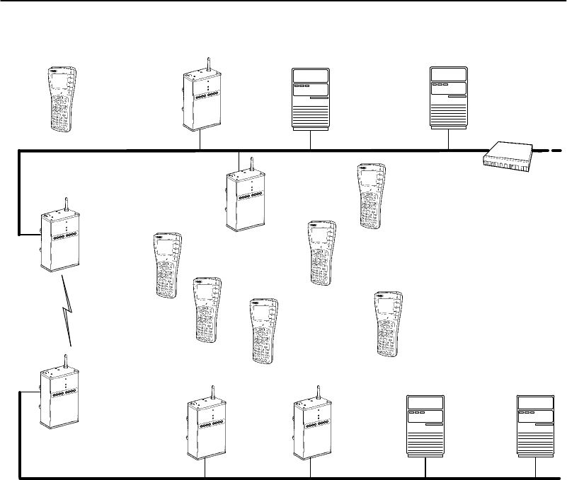
SECTION4"Configuration
6710 Access PointUser’sGuide 4-49
Novell Server
Distribution LAN
IPWireless
Stations
AP1
(SuperRoot)
Figure 4-3
Access PointsServicing IPWireless Stations
IPHost
IPX Router
AP2
AP4
AP5
AP3
AP6IPX HostIPHost
SecondaryLAN
Example 1
Access points1,3,5,and6inFigure4-3service onlyIP
wireless stations.Intheseaccess pointsitisdesirableto
pass necessaryIPtraffic,buteliminateunnecessaryIPX
traffic.Thesedonotneedtobeforwardedtothesecondary
LAN.Inthiscaseitisnotnecessarytousethe
[SubTypes1]or[SubTypes2]configuration.

SECTION4"Configuration
4-50 6710 Access PointUser’sGuide
Inexample1,[FrameTypes]is setasfollows:
Action Scope
DIX-IP-TCP Ports <Pass> <All>
DIX-IP-UDP Ports <Pass> <All>
DIX-IP-Other Protocols <Pass> <All>
DIX-IPX Sockets <Drop> <All>
DIX-Other EtherTypes <Pass> <Unlisted>
SNAP-IP-TCP Ports <Pass> <All>
SNAP-IP-UDP Ports <Pass> <All>
SNAP-IP-Other Protocols <Pass> <Unlisted>
SNAP-IPX Sockets <Drop> <All>
SNAP-Other EtherTypes <Pass> <Unlisted>
802.3-IPX Sockets <Pass> <Unlisted>
802.2-IPX Sockets <Pass> <Unlisted>
802.2-Other SAPs <Pass> <Unlisted>
Example 2
Access points2 and4inFigure4-3serviceIPwireless
stationsaswell aswiredIPandIPXhostsonthesecondary
LAN.Theseaccess pointshaveanadditionalrequirement
topass IPXtraffic.
TheIPXrouterinthisnetworkperiodicallysendsIPX-RIP
(RoutingInformationProtocol) framesfor coordinatingwith
other routers.Thesedonotneedtobeforwardedtothe
secondaryLANbecausethesecondaryLANdoesnot
containarouter.
TofiltertheRIPframes,itisnecessarytousethe
[SubTypes1]configurations.The examplesetsfiltersfor
three differentcases: DIX,802.2,or802.3SNAPframes.
Inmanyactualnetworks,onlyone ofthesewouldbe
required,sinceall stationswouldbeconfiguredforone of
thethree options.

SECTION4"Configuration
6710 Access PointUser’sGuide 4-51
Inexample2,[FrameTypes]is setasfollows:
Action Scope
DIX-IP-TCP Ports <Pass> <All>
DIX-IP-UDP Ports <Pass> <All>
DIX-IP-Other Protocols <Pass> <All>
DIX-IPX Sockets <Pass> <Unlisted>
DIX-Other EtherTypes <Pass> <Unlisted>
SNAP-IP-TCP Ports <Pass> <All>
SNAP-IP-UDP Ports <Pass> <All>
SNAP-IP-Other Protocols <Pass> <Unlisted>
SNAP-IPX Sockets <Pass> <Unlisted>
SNAP-Other EtherTypes <Pass> <Unlisted>
802.3-IPX Sockets <Pass> <Unlisted>
802.2-IPX Sockets <Pass> <Unlisted>
802.2-Other SAPs <Pass> <Unlisted>
[SubTypes1]optionsareconfiguredtodropIPXRIPfor
802.2, DIX,and802.3frames. DIXisalreadyspecifiedasa
predefinedfilter.For802.2 and802.3frames,itis
necessarytouseauser-definedfilter.
Inexample2,[SubTypes1]is setasfollows:
Action SubType Value
DIX-ARP <Pass> <DIX-EtherType> 08 06
SNAP-ARP <Pass> <SNAP-EtherType> 08 06
802.2-IPX-RIP <Drop> <802.2-IPX-Socket> 04 51
802.2-IPX-SAP <Pass> <802.2-IPX-Socket> 04 53
NNL <Pass> <DIX-EtherType> 87 5b
NETBIOS <Pass> <802.2-SAP> f0 f0
1 <Drop> <DIX-IPX-Socket> 04 51
2 <Drop> <802.3-IPX-Socket> 04 51
3 <Pass> <DIX-IP-TCP-Port> 00 00
4 <Pass> <DIX-IP-TCP-Port> 00 00

SECTION4"Configuration
4-52 6710 Access PointUser’sGuide
[AdvancedRXFilter]
Ifyou needmoreflexibilitythanthatprovidedby[Normal
RXFilter],youcan usethetablesfor[AdvancedRXFilter]
tospecifyadditionalfilters.Settingsfor[AdvancedRX
Filter]executeafterthosefor[NormalRXFilter].For
example,if [NormalRXFilter]droppedaframe,theframe
cannotbe“undropped.”If [NormalRXFilter]passeda
frame,[AdvancedRXFilter]thenexecutes.
Specifyinganadvancedfilterfor[AdvancedRXFilter]is
morecomplicatedthanspecifyingonefor[NormalRX
Filter].Ifpossible,use[NormalRXFilter]tosetfilters.
[AdvancedRXFilter]optionsare:
[Expressions]
[Values]
[Expressions]
Use[Expressions]to enterexpressionsusedtomatchthe
patterns storedinpatternliststoconsecutivebytesin
receivedEthernetframes.SettingsforExpressionsexecute
insequenceuntil adeterminationismadetopass ordrop
theframe,asfollows:
"IfthelastThenlistedinthistableisThenDrop,the
table’sdefaultisanimpliedElsePass.
"IfthelastThenisThenPass,thedefaultisanimplied
ElseDrop.
TheValueTabledisplaysthefilterexpressionstobe
executed:

SECTION4"Configuration
6710 Access PointUser’sGuide 4-53
ExprSeq Offset Mask Op Value Id Action
1 0 0 <EQ> 0 <And>
2 0 0 <EQ> 0 <And>
3 0 0 <EQ> 0 <And>
.
.
.
22 0 0 <EQ> 0 <And>
Filterexpressionshavethefollowingsettings:
ExprSeq 0
Offset 0
Mask
Op <EQ>
Value Id 0
Action <Pass>
ExprSeq
ExprSeqcontainsasequencenumberthatorders
expressionsinascendingorder.Itisamethodofchanging
thesequence execution.Thepromptis:
Range is:
0..65535
Thedefaultis0.Changethesenumbersasneededfor
reordering.Afteryousavethechanges(throughtheWrite
command),thestatementsarephysicallyreorderedand
renumbered.

SECTION4"Configuration
4-54 6710 Access PointUser’sGuide
Offset
This settingdefinesthe offsetinareceivedEthernetframe
tomatchthepatterns.Thepromptis:
Range is:
0..65535
Aframematchesapatternlistifthemaskedbytesat the
specifiedoffsetintheframematchanyofthemasked
patternsinthepatternlist.Thedefaultis0.
Mask
This settingindicatesthebitsthataresignificantat the
specifiedoffset.Thepromptis:
Range is:
8 hex pairs
Thedefaultis“” (anemptystring).
Thelengthofthismaskdeterminesthenumberof
characterscomparedat the offset.Ifthisfieldis“” (an
emptystring,thedefault),thelengthofthefieldis
determinedbythelongestvalueintheValueTablewiththe
matchingValueId.
Op
Opisamemorycomparisonoperatorinthefollowingchart.
OperatorDescription
LT Less thanonevalue.
LELess thanorequalto onevalue.
EQ(default)Equaltoanyinthelist.
NENotequaltoanyinthelist.
GEGreaterthanorequalto onevalue.
GTGreaterthanonevalue.

SECTION4"Configuration
6710 Access PointUser’sGuide 4-55
ValueId
Thefieldat thespecifiedoffsetiscomparedwithvaluesin
theValueTablewiththeValueId.Thepromptis:
Range is:
0..255
Thedefaultis0.When usingacomparisonoperatorthat
requiresasinglevalue(LT,LE, GE,andGT),onlythefirst
valuefoundwill becompared.
Action
TheActionsettinginstructstheEthernetdriverand
indicateswhatshouldhappenwhenthisexpressionistrue.
Settingsare:
And
Pass
Drop
SettingDescription
AndInstructsEthernetdrivertocontinuewiththe
nextsimple expression,ifthe expressioncondi-
tionis satisfied.Two ormoresimple expressions
areANDedtogethertoformacomplexexpres-
sion.
Pass
(default)InstructsEthernetdrivertoaccept theframefor
furtherprocessingand pass theframeuptothe
bridginglayer(theframeisnotdiscarded).
DropInstructsEthernetdrivertoreject theframe.

SECTION4"Configuration
4-56 6710 Access PointUser’sGuide
[Values]
Use[Values]to enterpatternliststhatcontainbyte
patternsthat matchconsecutivebytesinreceivedEthernet
frames.Settingsfor[Values]arereferencedbytheValueId
from theExpressionTable.Thevaluestobeusedinafilter
expressionareasfollows:
Value Id Value
1 0
2 0
3 0
.
.
.
22 0
Filterexpressionvalueshavethefollowingsettings:
Value Id 0
Value
SettingDescription
ValueIdAnidentifierusedbyanexpressionintheExpres-
sionTable.Therangeis0(default)to255.All
valueswiththesameidentifierareconsideredto
beinthesamelist.When usedinanexpression
thatallowsonlyonevalue(thatis,LT,LE, GE,or
GT),onlythefirstvalueinthelistisused.
ValueOne ofthevaluestobecompared.Therangeis8
hexadecimalpairs.

SECTION4"Configuration
6710 Access PointUser’sGuide 4-57
[Bridging]
[Bridging]optionsare:
Bridge Priority 1
Status <Enabled>
Flood Register <Disabled>
BridgePriority
Thebridgepriorityallows selectionoftheaccess point
servingasadesignatedbridgeforasecondaryLAN.As
withtherootpriority,thebridgepriorityallowsdesignation
ofaccess pointsasprimaryorfallbackbridges.Theprompt
is:
Range is:
0..7
"NOTE:The S-UHFradio option doesnotsupportdesignated bridging.
DesignatedBridgeCandidates
Access pointswitha bridgeprioritybetween1(default)and
7 arecandidatestobecomethedesignatedbridge;access
pointswitha bridgepriorityof0 areprohibitedfrom
bridging.Theaccess pointwiththehighestbridgepriority
(otherthan0)becomesthedesignatedbridgewheneveritis
connected(poweredonandactive)tothesecondaryLAN.
Iftwoaccess pointshavethesamebridgepriority,the
access pointwiththehighestEthernetaddress becomesthe
designatedbridge.However,alowerbridgepriorityaccess
point maybecomethedesignatedbridgeifthewireless link
toahigherbridgepriorityaccess pointisunacceptable.

SECTION4"Configuration
4-58 6710 Access PointUser’sGuide
DesignatedBridgeSelection
Ifthecurrentdesignatedbridgegoesoffline,theremaining
candidatesnegotiatetodeterminewhichonebecomesthe
newdesignatedbridge.
Summary
Insummary,thedesignatedbridge:
"PhysicallyconnectstoasecondaryEthernetLAN.
"Iswithintheradiocoverageareaofanaccess pointon
thedistributionLAN.
"Hasthehighestnonzerobridgepriority.Ifithasthe
samebridgepriorityasanotheraccess point,thenit
hasthehighestEthernetaddress (unless theaccess
pointwiththehighestpriorityisoutofradiorange).
Status
TheStatusoptiondeterminesiftheaccess pointcan
functionasadesignatedbridge.Settingsare:
Enabled
Disabled
SettingDescription
Enabled(default)Thisaccess point mayfunctionasthe
designatedbridgeforthesecondary
EthernetLAN.
DisabledThisaccess pointcannotbethedesignated
bridgeforthesecondaryEthernetLAN.
TheDisabledsettinghasthesame effectas
settingBridgePriorityto0.TheDisabled
settingisvaluablefordebug.

SECTION4"Configuration
6710 Access PointUser’sGuide 4-59
Flood Register
Asthedesignatedbridgeforthis secondaryEthernetLAN,
theaccess pointcanregisterthetype of framesitexpectsto
flood—unicast,multicast,orboth.Thisinformationis
registeredwithotheraccess points.Setting[Global
Flooding]settingsinthesuper rootoverridesindividual
FloodRegistersettingsindesignatedbridges.
FloodRegistersettingsare:
Disabled
Multicast
Unicast
Enabled
"NOTE:Set the sameFlood Registersetting in anyaccess point thatisa
candidateto becomethe designated bridge forasecondaryEthernet
LAN.
SettingDescription
Disabled
(default)Nofloodingoccurs.(Thesuper root,however,
enablesfloodingiftheOutboundtoSecondaries
MulticastorUnicastoptionis set toEnabled.*)
MulticastEnablesmulticastflooding.(Thesuper root
disablesmulticastfloodingiftheOutboundto
SecondariesMulticastoptionis set toDisabled.*)
Nounicastfloodingoccurs.(Thesuper root
enablesunicastfloodingiftheOutboundto
SecondariesUnicastoptionis set toEnabled.*)
UnicastEnablesunicastflooding.(Thesuper rootdisables
unicastfloodingiftheOutboundtoSecondaries
Unicastoptionis set toDisabled.*)
Nomulticastfloodingoccurs.(Thesuper root
enablesmulticastfloodingiftheOutboundto
SecondariesMulticastoptionis set toEnabled.*)
*See page4-29 formore informationaboutOutbound to
Secondaries.

SECTION4"Configuration
4-60 6710 Access PointUser’sGuide
SettingDescription
EnabledMulticastandunicastfloodingoccurs.(Thesuper
rootdisablesfloodingiftheOutboundto
SecondariesMulticastorUnicastoptionis set to
Disabled.*)
*See page4-29 formore informationaboutOutbound to
Secondaries.
Globalfloodingsettingsinthesuper root takeprecedence
overFloodRegistersettings.
WLIFOptions
"NOTE:AppendixBprovidesadditional information about the WLIFradio.
Use[WLIF]tosetProxim2.4GHzradio options:
Security Id “NORANDOWL”
Node Type <Master>
[Master Parms]
MAC Config <Default>
[Manual MAC Parms]
"NOTE:[SlaveParms]appearsinstead of [MasterParms]ifNode Type is set
toSlave. [ManualMACParms]appearsifMAC Configis set to
Manual.
SecurityId
SecurityId preventsunauthorizedwireless stationsfrom
associatingwiththisaccess point.Thepromptis:
Range is:
20 chars

SECTION4"Configuration
6710 Access PointUser’sGuide 4-61
ThedefaultsecurityIDisNORANDOWL.
All WLIFaccess pointsandwireless stationsinthenetwork
musthavethesamesecurityIDtocommunicate.The
securityIDiscasesensitive.Thatis,iftheaccess point’s
securityIDisin uppercase,thewireless station’smustalso
bein uppercase.Refertothewireless station’suserguide
formoreinformationaboutsettingits securityID.
NodeType
NodeTypedeterminesifthisradioisaMastertowhich
wireless stationsattach,orisaSlaveradiothat must
attachtoaMaster.ConfigurationofaWLIFradioasa
Slaveisnecessaryiftheaccess pointisconfiguredasa
wireless access point,orthedesignatedbridgefora
secondaryLAN.
Configurationasawireless access pointrequires
installationoftwoWLIFradios:oneMasterandoneSlave.
TheMaster radioservices stationslocaltothewireless
access point.TheSlaveradioprovidescommunications
betweenthewireless access pointandthenetwork
infrastructure.Figure4-4onpage4-65 showsanetwork
example.
NodeType optionsare:
Master
Slave
SettingDescription
Master
(default)Theportisconfiguredtocommunicatewith
wireless stations.
SlaveTheportisconfiguredtocommunicatewith
otheraccess points.

SECTION4"Configuration
4-62 6710 Access PointUser’sGuide
[MasterParms]
[MasterParms]containsparameterstheaccess pointneeds
whenyouconfigureitasaMaster radio.Settingsare:
Channel 1
Subchannel 1
Wireless Hops <Disabled>
Channeland Subchannel
Channelsetsthisradio’shoppingsequence.Subchannel
enablesaccess pointstosharethesamechannelwithout
receivinganotheraccess point’sframes.Thepromptfor
ChannelandSubchannel is:
Range is:
0..15
ThedefaultforChannelandSubchannel is1.
Thechannelmustbeuniqueforeachaccess pointlocated
close enoughtogether(withinthesamecoveragearea)such
thatawireless stationmaychoosetoconnectwithanyof
them.Tomaximizetheavailablebandwidth,thechannel
andsubchannelpairshouldbeuniqueforeachclosely
locatedaccess point.
Whenchannelsaredifferentamongaccess points,anaccess
pointcannotreceiveanotheraccess point’straffic.An
access pointdiscardsframesifthechannelandsubchannel
IDsintheframeheaderdonot matchtheaccess point’s
channelandsubchannelsettings.
Twoaccess pointsondifferentsubchannels sharethesame
hoppingsequence,butbehaveasiftheywere ondifferent
channels.

SECTION4"Configuration
6710 Access PointUser’sGuide 4-63
NetworkWith15 orFewerAccess Points
If15 orfeweraccess pointsare onthenetwork,thechannel
shouldbedifferentforall access points.Thesubchannel
canbethesameasordifferent thanthechannel.
EXAMPLE1:The channeland subchannelcouldbesetasfollows(the access
pointnumberinthe firstcolumnisarbitrary):
Access PointChannelSubchannel
1 1 1
2 2 1
3 3 1
4 4 1
5 5 1
6 6 1
7 7 1
8 8 1
9 9 1
10 10 1
11 11 1
12 12 1
13 13 1
14 14 1
15 15 1
NetworkWith16 orMoreAccess Points
Whenthenumberofin-rangeaccess pointsis16 ormore,
channelsmustbereused.Thechannelcanbethesamefor
two ormore,but theyshouldhavedifferentsubchannels.
Inthiscase,access pointsusingthesamechannelreceive
trafficforanotheraccess pointbutdiscardframeswiththe
incorrectsubchannel.Tominimizeinterference,access
pointsusingthesamechannel(butdifferentsubchannels)
shouldbephysicallylocatedoutsidetheradiorange ofone
another.

SECTION4"Configuration
4-64 6710 Access PointUser’sGuide
EXAMPLE2:If 43 access pointsareonthe network,1to15could be assigned the
channeland subchannelnumbersinthe previousexample.Access
points16 to43couldbesetasfollows(the access pointnumberin
the firstcolumnisarbitrary):
Access PointChannelSubchannel
16 1 2
17 2 2
18 3 2
19 4 2
20 5 2
21 6 2
22 7 2
23 8 2
24 9 2
25 10 2
26 11 2
27 12 2
28 13 2
29 14 2
30 15 2
31 1 3
32 2 3
33 3 3
34 4 3
35 5 3
36 6 3
37 7 3
38 8 3
39 9 3
40 10 3
41 11 3
42 12 3
43 13 3
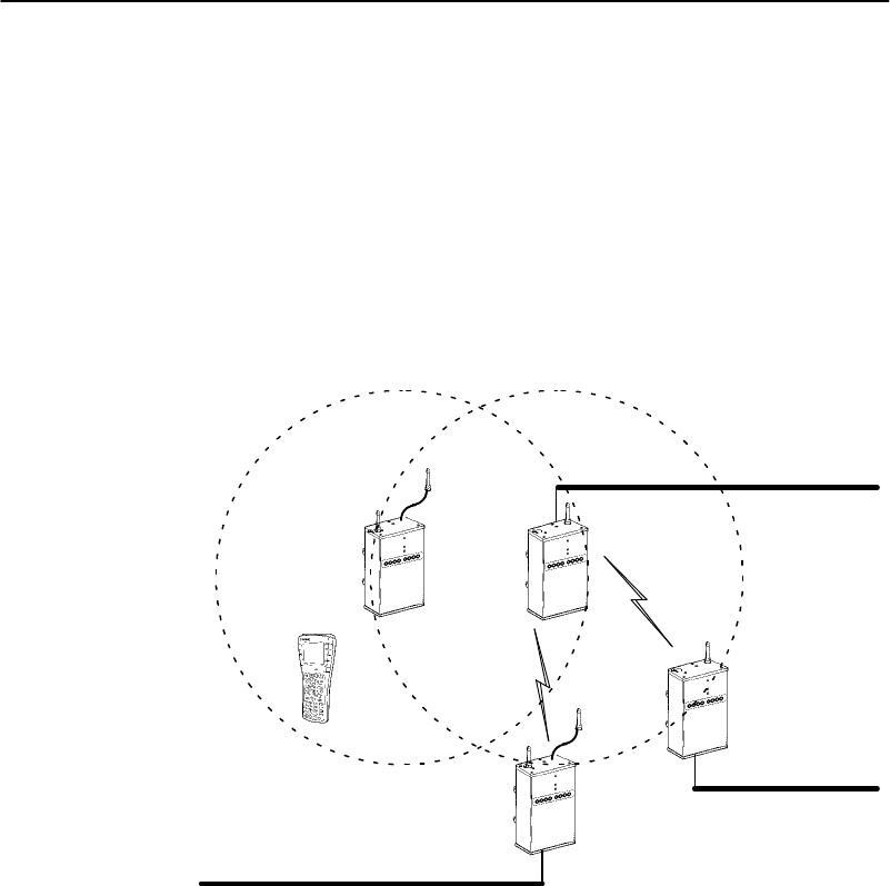
SECTION4"Configuration
6710 Access PointUser’sGuide 4-65
Wireless Hops
Tocreateawireless hop,youmustenable one ormore
WLIFradiosonthedistributionLANaswireless hopping
MastersandthenconfiguretheSlavestations(through
[SlaveParms]) toconnect totheseMasters.
EXAMPLE:InFigure 4-4, two access pointshavetwoWLIFradios. One radiois
configured asaMasterto provide the wireless connection tothe
distribution LAN.The other radiois configured asaSlavetoservice
wireless station traffic.
Slave
Figure 4-4
Wireless Hopping Through WLIFRadios
Ethernet (Distribution)LAN
SecondaryLAN
SecondaryLAN
Master
Slave
Master
Slave
Master
"NOTE:Forbestperformance,use one ortwo externalantenna kitswhen
using twoWLIFradios.Aminimumseparation of10 feet(3meters)
between antennasisrequired.

SECTION4"Configuration
4-66 6710 Access PointUser’sGuide
SettingsfortheMasterare:
Enabled
Disabled
SettingDescription
EnabledSetsupthisaccess point’sradioport towireless
hop.Thisaccess pointhonorsconnectionsfrom
anaccess pointwithaSlaveradio.
Disabled
(default)Preventsthisaccess point’sradioportfrom
wireless hopping.Thisaccess pointdoesnot
honor connectionsfromanaccess pointwitha
Slaveradio.
[Slave Parms]
[SlaveParms]containsparametersthisradioneedswhen
youconfigureitasaSlaveradio. Optionsare:
Channel Subchannel
Master 1 1 1
Master 2 0 0
Master 3 0 0
Master 4 0 0
Master 5 0 0
Master 6 0 0
Master 7 0 0
Master 8 0 0
FortheWLIFradiotowireless hop,atleastoneaccess
pointonthesecondaryLANmustbe equippedwithaWLIF
radioconfiguredforSlavemode.ThesecondaryLANcan
be one ofthefollowing:

SECTION4"Configuration
6710 Access PointUser’sGuide 4-67
"AnEthernetsegment.
"Theradiorange ofasingleaccess pointwithtwo
radios. Oneradiomustbe operatingasaMasterto
servicewireless stationtraffic.The other radiomust
be operatingasaSlavetoprovidethewireless hopto
thedistributionLAN.
"NOTE:You mustset the RootPriorityforthe access pointwiththe Slave
radioto0to preventit frombecoming the open wireless LANsuper
root.
Youmustprevent theaccess pointwiththeSlaveradio
fromsynchronizingwithMaster radiosinaccess points
attachedtothesamesecondaryLAN.Toidentifythe
MasterswithwhichtheSlaveisallowedtosynchronize,do
thefollowing:
1.Identifyeightorfewer Masterstationswithwhichthe
SlaveisallowedtosynchronizebyselectingMaster
<number>.
2.Enterthechannelandsubchannelpairsthatyouset
forChannelandSubchannel,asfollows:
Channel 1
Subchannel 1
Setting*Description
ChannelChanneltheMasterWLIFradioisusing
(defaultis1).
SubchannelSubchanneltheMasterWLIFradiois
using(defaultis1).
*Channeland Subchannelare discussedonpage4-62.

SECTION4"Configuration
4-68 6710 Access PointUser’sGuide
TheSlaveaccess pointsynchronizeswithMasterswhose
channelandsubchannelappearinthelistofconfigured
Masters.Precedenceisgivenbythe orderofthelist.
Master1hashighestprecedence;Master8haslowest.
Channelandsubchannelsettingscanbe0, where0means
“donotcare.”Forexample:
"Youcanset theMaster1channelto0 andsubchannel
to1.TheSlavesynchronizeswithanyMasteronany
channelaslongastheMaster’s subchannel is1.
"Youcanset theMaster1channelto0 andsubchannel
to0, whichmeans“donotcare.”TheSlave
synchronizeswithanyMaster.
Rememberthat:
"AnyMasterwithwhichtheSlaveisallowedto
synchronizemusthaveWireless Hopsenabled.
"ASlavestationmusthavearootpriorityof0.
"ASlavestationmustnotbeallowedtosynchronize
withaMaster connectedtoitsownsecondaryLAN.
MAC Config
UseMAC Configoptionsto enhancetheperformance ofthe
WLIFradio. Optionsare:
Default
Interference
Throughput
Manual
"NOTE:AninefficientMAC Configradiosetting can adverselyaffect the
performance ofyouropen wireless LAN.You shouldchange MAC
Configradiosettingsonlyunderthe directsupervision ofaSystems
Engineer.

SECTION4"Configuration
6710 Access PointUser’sGuide 4-69
SettingDescription
Default
(default)Usesthefactory-setsettingsfortheradioproto-
col(settingsarelocatedunder[ManualMAC
Parms]).TheDefaultsettingshouldbeusedfor
normaloperation.
InterferenceOptimizesthesettingsfortheradioprotocolfor
betterperformanceinenvironmentswith high
interference ormultipath.
ThroughputOptimizesthesettingsfortheradioprotocolfor
betterperformance of filetransferoperationsin
openoruncongestedenvironments,suchasof-
ficeareas.
ManualAllowsyoutoadjustWLIFMAC parameters
(locatedunder[ManualMAC Parms]) individu-
ally.Donotselect this settingunless aSystems
Engineer directsyoutodoso.
[ManualMAC Parms]
"NOTE:Adjusting the settingsfor[ManualMACParms]isnotadvised unless
instructed byTechnicalSupport.
Occasionally,asite’sWLIFradioparametersmayneedto
befine-tuned. Optionsfor[ManualMAC Parms]enablethe
CustomerResponseCentertofine-tunethisaccess point’s
performance.Settingsare:
Hop Period <200ms>
Beacon Frequency 2
Deferral Slot <Default>
Fairness Slot <Default>
Fragment Size 310
Transmit Mode <AUTO>
Norm Ack Retry 255
Frag Ack Retry 255
Norm QFSK Retry 255
Frag QFSK Retry 255

SECTION4"Configuration
4-70 6710 Access PointUser’sGuide
Hop Period
HopPeriodsetsthehoppingtimeperiod, whichdetermines
howlongtheradiostaysonafrequencyinthehopping
sequencebeforesteppingtothenextfrequency.Settings
are:
100 ms
200 ms
400 ms
Thedefaultis200 ms.Alongerperiodresultsinbetter
throughput.Ashorterperiodresultsinfaster roaming
responseandbetterimmunityfrominterference.
Beacon Frequency
Theaccess pointperiodicallytransmitsa beacontoallow
Slaveradios(wireless stations)toquicklyscaneach
frequencytofindaMaster(anaccess point).Beacon
Frequencyisthenumberofhopsthatoccurbetween
beacons.Thepromptis:
Range is:
1..7
Asettingof1isonebeacononeveryhop.Asettingof7is
onebeaconevery7hops.Thedefaultis2.
Youcanreducethescantimeand,therefore,thetime
requiredfor roamingbyincreasingthebeaconfrequency.
Morebeaconsmayletwireless stations synchronizefaster,
butbeaconsusebandwidthotherwiseavailablefordata.
DeferralSlotand Fairness Slot
Thenumberofdeferralandfairness slotsdeterminesthe
averageback-off timewhenthechannel is sensedtobe
busy.

SECTION4"Configuration
6710 Access PointUser’sGuide 4-71
Settingsforbothoptionsare:
Default
1
3
7
ThedefaultsettingisDefault.Youcandothefollowing:
"Reducethenumberofslotsonlightly-loadednetworks
toincreasethroughput.
"Increasethenumbertohelp preventrepeated
collisionsunderaheavy load.
YoucansetFairness Slotasfollows:
"Increasethenumbertoprioritizethechannelaccess
fornodesthathavebeenwaitingthelongest toaccess
thechannel.
"Decreasethenumbertominimizeinitialback-off
delays.
FragmentSize
FragmentSizedeterminesthemaximumsize ofafragment
tobesentoverthisradioduringinterference.Theprompt
is:
Range is:
1..1540
Thedefaultis310.
IftwoACKerrorsoccurinarowduringthetransmissionof
alargedataframe,itsplitsintotwo ormorefragmentsand
eachfragment transmits separately.AnACKerroroccurs
ifa acknowledgmentframeisnotreceivedfrom the
destination node.

SECTION4"Configuration
4-72 6710 Access PointUser’sGuide
Smallerfragmentsmayallowsuccessfuloperationinan
environmentwithahighlevelofinterferenceat the
expense ofthroughput.
Transmit Mode
TransmitModemodulatesthetransmitsignalandsetsthe
bitspersecond.Settingsare:
BFSK
QFSK
AUTO
SettingDescription
BFSKBinaryFrequencyShiftKeying.Transmitsat0.8
Mbpspersecond. Dataistransmittedbyshifting
betweentwofrequenciestorepresentonebitof0
or1.BFSKhasextendedrange overQFSKat the
expense ofthroughput.
QFSK QuadratureFrequencyShiftKeying.Transmitsat
1.6Mbpspersecond. Dataistransmittedbyshift-
ingamongfourfrequenciestorepresent twobitsof
0or1. QFSKhasbetterthroughputoverBFSKat
the expense ofrange.
AUTO
(default)Automaticallyadaptsthebitratetothe error
conditions.Thetransmit modeisautomatically
selectedforthebestrangeandthroughput.
Norm Ack Retry
NormAckRetryisthenumberoftimesanyunfragmented
frame(QFSKorBFSK)isresentunsuccessfullybefore
fragmenting.Thepromptis:
Range is:
1..255

SECTION4"Configuration
6710 Access PointUser’sGuide 4-73
ThenumberincludesretriesthatoccurredinQFSKmode,
andshouldbelargerthanNormQFSKRetry.Avalue of
255 (default)indicatesthat theradiomaychoosean
optimumvalue.
FragAck Retry
FragAckRetryisthenumberoftimesanyfragmented
frame(QFSKorBFSK)isresentunsuccessfullybefore
failure.Thepromptis:
Range is:
1..255
FragAckRetryshouldbelargerthanFragQFSKRetry.A
settingof255 (default)indicatesthat theradiomaychoose
anoptimumvalue.
Norm QFSK Retry
NormQFSKRetryisthenumberoftimesan unfragmented
QFSKframeisresentunsuccessfullybeforeswitchingto
BFSK whenTransmitModeisAUTO. Thepromptis:
Range is:
1..255
TheretriesthatoccurarealsocountedbyNormAckRetry.
NormQFSKRetryshouldbesmallerthanNormAckRetry.
Thedefaultis255.
FragQFSK Retry
FragQFSKRetryisthenumberoftimesafragmented
QFSKframeisresentunsuccessfullybeforeswitchingto
BFSK whenTransmitModeis set toAuto.Thepromptis:
Range is:
1..255

SECTION4"Configuration
4-74 6710 Access PointUser’sGuide
Thedefaultis255.
TheretriesthatoccurarealsocountedbyFragAckRetry.
FragQFSKRetryshouldbesmallerthanFragAckRetry.
900 MHzOptions
"NOTE:AppendixCprovidesadditional information about the 900 MHzradio.
Use[Falcon]toset900 MHzradio options:
File Name ”falcon_d.29k”
Mode-Channel <DS 225K Channel 25>
FileName
FileNameisthename oftheradio’sdriversoftware. Only
changethisnamewhendirectedtodosobyaSystems
Engineer.Normally,theprogram’sfilenameshouldnotbe
changed.
Mode-Channel
Modesetsthebitrate optionforthe900 MHzradio.
Generally,thehigherthebitrate,thelowertherange ofthe
access point.Channeldefinesafrequencyrangethatisa
small portionoftheavailablebandwidth.
Variouscommunicationmodesareavailable, whichenable
youtobalancetheneedfor radiocoveragewiththeneedfor
speed.Select theMode--Channeloptiontodisplaythelist
ofmodeandchannelcombinations, whichare
country-dependent.

SECTION4"Configuration
6710 Access PointUser’sGuide 4-75
Forexample,intheUnitedStatesthefollowing
combinationsarevalid:
DS 225K-Channel 25
DS 090K-Channel 10
DS 090K-Channel 15
DS 090K-Channel 20
DS 090K-Channel 25
DS 090K-Channel 30
DS 090K-Channel 35
DS 090K-Channel 40
DS 450K-Channel 25
Thefollowingchartdescribesthesettings showninthe
previous samplescreen:
SettingDescription
DS225K--Channel25 UsesoneDirectSequencedchannelat
225,000 bitspersecond.Thisone
moderate-speedchannelusesall avail-
ablebandwidth. DS225Kismode1.
DS090K--Channel10
through
DS090K--Channel40
Use one ofseveralDirectSequenced
channelsat90,000 bitspersecond.
Sevenlow-speedchannels sharethe
availablebandwidth. DS90Kismode
2.
DS450K--Channel25 UsesoneDirectSequencedchannelat
450,000 bitspersecond.Thisone
high-speedchannelusesall available
bandwidth. DS450Kismode3.
900 MHzradio optionsforawireless stationareset
throughitsAdvancedSetupfirmwaremenus.Wireless
stationandaccess pointsettingsmustmatch.Refertothe
wireless station’suserguideformoreinformationabout
AdvancedSetup.

SECTION4"Configuration
4-76 6710 Access PointUser’sGuide
S-UHFOptions
"NOTE:AppendixDprovidesadditional information about the S-UHFradio.
Use[UHF]tosetS-UHFradio options:
File Name “synuhf_d.29k”
Call Sign “”
Frequency (First frequency in list.)
Master Mode <Disabled>
Attach Priority <High>
"NOTE:AttachPrioritydisplays ifMaster Mode is set toDisabled.
FileName
FileNameisthename oftheradio’sdriversoftware. Only
changethisnamewhendirectedtodosobyaSystems
Engineer.Normally,theprogram’sfilenameshouldnotbe
changed.
Call Sign
"NOTE:Ignorethisoption ifyoursiteisoutside of the United States.
Call Signdisplaysyournetwork’scallsign.Thepromptis:
Range is:
12 chars
AgenciesthatallocateS-UHFfrequencies,suchasthe
FederalCommunicationsCommission(FCC)intheUnited
States,mayrequirethat thisaccess pointperiodically
transmitacallsign.

SECTION4"Configuration
6710 Access PointUser’sGuide 4-77
ThecallsignisgrantedaspartoftheFCC licenseprocess.
Insert thecallsignfrom theFCC licensecertificateat the
callsignprompt.
Frequency
TheFrequencyoptiondisplaysalistof frequencies
programmedat thefactory.Someradioshavemultiple
frequencies.Forexample:
466170000 Hz
530000000 Hz
Thedefaultfrequencyisthefirstfrequencyprogrammed
intothelist. Duetoregulatoryconstraintsinmost
countries,frequenciescanonlybeprogrammedbythe
factoryorservicecentersequippedtomakethischange.
MasterMode
Access pointswiththeS-UHFoptioninstalledcanoperate
withMaster Mode enabledordisabled.Master Modemay
improveperformanceinsome environments.Itshouldonly
be enablediftheaccess pointradiocoverageareadoesnot
overlapotheraccess pointsoperatingonthesame
frequency.IfMastermodeisdisabled,thisrestrictiondoes
notapply.Anaccess pointoperatingwithMaster Mode
disabledmayoverlapcoverageareaswithaccess pointson
thesame ordifferentfrequencies.
Master Modesettingsare:
Enabled
Disabled

SECTION4"Configuration
4-78 6710 Access PointUser’sGuide
SettingDescription
EnabledTheaccess pointcontrolschannelaccess for
stationsinitscoveragearea.
Disabled
(default)Access pointandstationscoordinatechannel
access.
AttachPriority
Iftheaccess pointisoperatingwithMaster Modedisabled,
theattachpriorityoftheaccess pointcanbespecified.
Stationsinthecoverageareaoftwoaccess pointswith
differentattachprioritiesnormallyattachtothehigher
priorityaccess point.However,attachpriorityisusedin
combinationwithotherfactors suchasloadingandsignal
strength,andastationmayattachtoalowerpriorityaccess
point thatprovidesa betterwireless link.Stationsignore
theattachprioritywhenselectingbetweentwoaccess
pointswiththesameattachpriority.
AttachPriorityisusefulwhenitisdesirabletohavea
redundantnetworkwithsomeaccess points servingas
standbyunits.Ifthehigherpriorityunitfails,stationsfall
backtothelowerpriorityunitwithinthesamecoverage
area.
AttachPrioritysettingsare:
High
Medium
Low
SettingDescription
High
(default)Highpriorityaccess point.
MediumMediumpriorityaccess point.
LowLowpriorityaccess point.

SECTION4"Configuration
6710 Access PointUser’sGuide 4-79
OWL/IPOptions
"NOTE:AppendixEprovidesadditional information about OWL/IPand
contains configuration examples.
Overview
TheOWL/IPextensiontothe openwireless LAN
architecture enablesawireless LAN installationtospan
multipleIPsubnets. OWL/IPisanadvancedcapability
thatrequiresbasicknowledge ofIPaddressingconventions
androutingtoconfigureanduse.Youshouldreviewthe
followingpagesandAppendixEbeforeusingthiscapability.
OWL/IPdoesthefollowing:
"Enablesaccess pointsondifferentIPsubnetstobelong
tothesamewireless network.
"Supportstransparentroamingofwireless stations
betweenaccess pointsondifferentsubnetswithout
losingnetworkconnectionsfor:
"Wireless stationsusingInternetProtocol(IP).
"Wireless stationsusingothernetworkprotocols,
suchasNORANDNetworkLayer(NNL),that
arenormallynotroutable.
OWL/IPisactivatedbyenablingtheOWL/IPportinthe
access point.TheportisanentrywaytoanIPtunnel
originatedbythesuper rootonthehome subnet,and
terminatedbyadesignatedbridge operatingonaremote
subnet(Figure4-5).Framesforwardedthroughthetunnel
are encapsulatedusingtheGenericRouterEncapsulation
(GRE)protocolrunningoverIP.
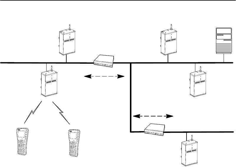
SECTION4"Configuration
4-80 6710 Access PointUser’sGuide
Serveror
Gateway
IP Station
SuperRoot
Figure 4-5
OWL/IPOverview
IPRouter
AP3
RemoteSubnet1
AP2
(Designated
Bridge)
Non-IP Station
IPRouterAP4
(Designated
Bridge)
AP1
HomeSubnet
Tunnel
Tunnel
RemoteSubnet2
Thesuper rootcanoriginateIPtunnelsto eightorfewerIP
addresses.Thenumberoftunnels supportedmaybemore
thanorfewerthaneight,dependingonthetype of
addressingusedandredundancyneedswithinthe
installation.
OWL/IPtunnelsareconfiguredusingthefollowingsteps:
1.Choosewhichsubnetisthehomesubnet,andwhich
subnetsareremotesubnets.Ifpossible,choosethe
subnet thatcontainsgatewaysorserversforwireless
stationsasthehomesubnet;however,theseservers
maybe onothersubnetsifnecessary.

SECTION4"Configuration
6710 Access PointUser’sGuide 4-81
Selectprimaryandfallbacksuper rootaccess points
onthehomesubnet.IPaddressesforwireless
stationsusedwithOWL/IPmustbelongtothehome
subnet.See OWL/IPlimitationsinAppendixE.
2.Selectaccess pointsoneachremotesubnet toserveas
designatedbridgesforthosesubnets.Configure
primaryandfallbackbridgeprioritiesunderthe
[Bridging]menu,describedonpage4-57.
ConfigureandrecordtheIPaddressesofall
designatedbridges. Designatedbridgecandidates
musthavepermanentIPaddresses.(DHCPshould
notbeusedtoassignIPaddressestoOWL/IP
designatedbridgesunless apermanentleaseis
specified,andtheaccess pointsarerebooted priorto
configuringOWL/IP.)
ItisnotnecessarytoconfigureGlobalFloodingor
FloodRegistersettingsforOWL/IPdesignated
bridges.ThesedonotapplytoOWL/IPdesignated
bridges.
3.Usethe[OWL/IP]menu toconfiguresuper root
candidatestoOriginateifRoot(describedonpage
4-82).ConfiguretheIPAddressesTable(page4-83)
usingtheappropriateaddressingfordesignated
bridgesoneachsubnet.All super rootcandidates
shouldbeconfiguredidentically.
4.ConfigureOWL/IP[TXFilter]settingsinall super
rootand designatedbridgecandidates.Adiscussionof
[TXFilter]startsonpage4-84.
5.FornetworksusingIPnetworkingonwireless
stations,use oftheARPserver capabilityintheaccess
pointis stronglyrecommended.AdiscussionofARP
serverstartsonpage4-36.

SECTION4"Configuration
4-82 6710 Access PointUser’sGuide
OWL/IPMenu
OWL/IPconfigurationmenu optionsare:
Mode <Listen>
[IP Addresses]
[TX Filter]
Insummary:
"TheModevaluespecifiesthe operationoftheaccess
pointwhentheOWL/IPportisenabled.Thisvalue
determineswhethertheaccess pointisconfiguredto
serveasthe originatororterminationofatunnel.
"The[IPAddresses]tableinthemenusprovidesthe
super rootwiththeinformation necessaryto establish
communicationswithdesignatedbridgesonremote
subnets.
"The[TXFilter]configurationmenu specifiestheframe
typesthatareforwardedthroughOWL/IPtunnels.
Mode
TheOWL/IPport maybeconfiguredwiththefollowing
options:
Listen
Originate if Root
SettingDescription
Listen(default)Access pointscanserveastheterminationof
atunnel iftheyarethedesignatedbridgefor
thesubnet,butcannotoriginateatunnel.
OriginateifRootAccess pointsoriginatetunnelsiftheyare
functioningas super rootforthenetwork.

SECTION4"Configuration
6710 Access PointUser’sGuide 4-83
[IPAddresses]
Theconfigurationscreenfor[IPAddresses]is:
Type Address
1 <Unicast> 0.0.0.0
2 <Unicast> 0.0.0.0
3 <Unicast> 0.0.0.0
4 <Unicast> 0.0.0.0
5 <Unicast> 0.0.0.0
6 <Unicast> 0.0.0.0
7 <Unicast> 0.0.0.0
8 <Unicast> 0.0.0.0
EachlineintheIPAddressesTablecontainsoneIPaddress
entry.Settingsare:
Type <Unicast>
Address 0.0.0.0
Type
TheTypesettingspecifiesthetype ofEthernetMAC
address usedbythesuper rootwhenforwardingframes
throughtheOWL/IPport.This settingallowsflexibilityin
configuringOWL/IProuting.Inmostcases,IPandMAC
address types shouldmatch.TheMAC frametypeandIP
address incombinationdictatehow GRE encapsulated
framesareforwardedtoIProuters.Settingsare:
Unicast
Multicast
Broadcast

SECTION4"Configuration
4-84 6710 Access PointUser’sGuide
SettingDescription
Unicast
(default)StandardIProutingisused.Framesare
forwardedtotheunicastMAC address ofthe
router.Thisiseitherthedefaultrouterspecified
inthe[Tcpip]configurationmenu oftheaccess
point,oranalternativerouterassignedbyICMP
redirect.
MulticastReservedforfutureuse.
BroadcastOWL/IPframesaresentusinganEthernet
broadcastaddress.Thiscapabilityallowsuse of
directed,andAll SubnetsIPaddressing.
Address
TheAddress settingisthetargetIPaddress oftheaccess
point towhichOWL/IPframesareaddressed.Theaddress
shouldbeconsistentwiththetype(unicast,multicast,or
broadcast).Thepromptis:
Range is:
4 nums 0..255
Entriesareclearedbysettingaddressesto0.0.0.0.
[TXFilter]
Configurationof filtersfortheOWL/IPportisdoneusing
thetransmitfilter([TXFilter]) option.Filtersetupis
similartothenormalEthernetfiltermenu,describedon
page4-43.Notethat theEthernetreceivefiltersandthe
OWL/IPtransmitfiltersarebothappliedtoframes
forwardedthroughatunnel.
OWL/IPfiltersrestrict theframetypesthatareallowedto
beforwardedfrom thehomesubnet toremotesubnets.By
default,filtersareprogrammedtodropall protocoltypes
exceptforthree protocols specifiedinthe[SubTypes1]
screen.ThetypesareNNLDIXtype875b,IPAddress
ResolutionProtocol(ARP)DIX0806,andICMP0001.

SECTION4"Configuration
6710 Access PointUser’sGuide 4-85
Thefilter configurationmustbechangedtoallow
forwardingofotherdesired protocols,includingTCPor
UDP.See AppendixEfordiscussionofOWL/IPrestrictions
and permanentfilters.Filtersmustbeconfiguredinall
super rootcandidatesandOWL/IPdesignatedbridges.
DefaultfiltersettingsforOWL/IPareshownbelow.
Action Scope
DIX-IP-TCP Ports <Drop> <Unlisted>
DIX-IP-UDP Ports <Drop> <Unlisted>
DIX-IP-Other Protocols <Drop> <Unlisted>
DIX-IPX Sockets <Drop> <All>
DIX-Other EtherTypes <Drop> <Unlisted>
SNAP-IP-TCP Ports <Drop> <All>
SNAP-IP-UDP Ports <Drop> <All>
SNAP-IP-Other Protocols <Drop> <All>
SNAP-IPX Sockets <Drop> <All>
SNAP-Other EtherTypes <Drop> <All>
802.3-IPX Sockets <Drop> <All>
802.2-IPX Sockets <Drop> <All>
802.2-Other SAPs <Drop> <All>
Defaultfiltersettingsfor[SubTypes1]areshownbelow.
Action SubType Value
DIX-ARP <Drop> <DIX-EtherType> 08 06
SNAP-ARP <Drop> <SNAP-EtherType> 08 06
802.2-IPX-RIP <Drop> <802.2-IPX-Socket> 04 51
802.2-IPX-SAP <Drop> <802.2-IPX-Socket> 04 53
NNL <Pass> <DIX-EtherType> 87 5b
NETBIOS <Drop> <802.2-SAP> f0 f0
1 <Drop> <DIX-IP-TCP-Port> 00 00
2 <Drop> <DIX-IP-TCP-Port> 00 00
3 <Drop> <DIX-IP-TCP-Port> 00 00
.
.
16 <Drop> <DIX-IP-TCP-Port> 00 00

SECTION4"Configuration
4-86 6710 Access PointUser’sGuide
SecurityOptions
Use[Security]toset thesepasswords:
Password “************”
Service Password <Enabled>
Advanced Password “************”
Password
Thisoptionisthetop-levelpasswordyou needtoaccess the
configurationmenus.Thepromptis:
Range is:
16 chars
Enter16 orfeweralphanumeric charactersforthis
password.Itiscaseinsensitiveandcanbeanycombination
ofletters,numbers,andsymbols.Forsecurity,the
passwordappearsasasterisksonthescreen.
Service Password
IntermecmaintainsaservicepasswordsoitsCustomer
ResponseCenter canconfigurethisaccess pointif
necessary.Forexample,ifyouforgetwhat the
configurationmenus’top-levelpasswordis,theCustomer
ResponseCenter canaccess themenusthroughtheservice
password.
Bydefault,theServicePasswordisenabled.Ifsettinga
servicepasswordviolatesyoursecurity guidelines,youcan
disableit.Ifitisalreadydisabledandyouforget the
configurationmenus’password,youmayneedtosendthis
access point toaServiceCentertobereconfigured.
Contact theCustomerResponseCenterformore
informationabout theservicepassword.See thePrefacefor
contactinformation.

SECTION4"Configuration
6710 Access PointUser’sGuide 4-87
AdvancedPassword
Whenyousetanadvanced password,itisrequiredto
configurethefollowing:
Security/AdvancedPasswordand Bridge/Ports/omdip
Thepromptis:
Range is:
16 chars
Enter16 orfeweralphanumeric charactersforthis
password.Itiscaseinsensitiveandcanbeanycombination
ofletters,numbers,andsymbols.Forsecurity,the
passwordappearsasasterisksonthescreen.
Combining RadioOptions
YoucancombineWLIF,900 MHz,andS-UHFradiosina
common networkbyfollowingbasicguidelinesforLANID.
Twoalternativesarepossible:sameLANIDand different
LANIDs.
SameLAN ID
UsingthesameLANIDforall radio optionsconfiguresall
access pointsintoasinglenetworkregardless ofradiotype.
Thisapproachallowsmanagementofasinglenetwork
usingtheOWLViewnetworkmanagementapplication.
AnEthernetpathorwireless hopmustexistfromall access
pointstothesuper rootandback-upsuper rootcandidates.
Inaddition,globallydistributedsystemparameters—
particularlyfloodinglevels—mustbeappropriateforall of
theinstalledradio options.

SECTION4"Configuration
4-88 6710 Access PointUser’sGuide
DifferentLAN IDs
UsingseparateLANIDsforeachradio optionconfiguresall
access pointswithdifferentradiosintoadistinctnetwork
regardless ofradiotype.It maybemoreappropriateifthe
installationtopology orapplications supported donotfit the
alternativethatusesthesameLANID. OWLViewshows
twodistinctLANsforthistype ofinstallation.
Creating aWebBrowserSession
"NOTE:The access point’s configuration menusare designed forHTML
Level2.0 orhigher.
Beforeyoucanconfiguretheaccess point throughaWeb
browser,youmustconnect theunit totheEthernetcable.
(See Section3,“Installation,”forhelp.)Youmustalso
performinitialconfigurationthroughtheDIAGport to:
"SetanIPaddress orDHCPservername.Youshould
alsoconfigureasubnet maskandIProuteraddress.
"Set theEthernetcabletype.
"NOTE:The access pointincludesan autodetect featurethatsensesthe
Ethernetmediumif trafficispresent. If no trafficispresenton the
cable, the systemsoftware defaultsto 10BASE-T.For most
installations,itisrecommended thatyou explicitly set the Ethernet
type.
Theaccess point mustgothroughitsbootsequencebefore
youcanconfigureit throughthebrowser.Ifyourebootit
whileyouareconfiguringit throughthebrowser,the
sessionterminates.Youcancreateanewsessionafterthe
access pointreboots.To establisha browsersession,see
Figure4-6 andtheprocedurefollowingit.
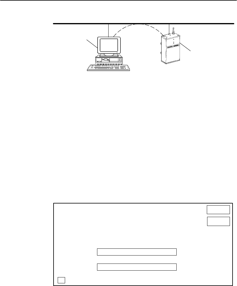
SECTION4"Configuration
6710 Access PointUser’sGuide 4-89
1.PlatformwithWeb browser
2.6710 Access Point
Figure 4-6
WebBrowserSession
HTTP
EthernetLAN
1
2
1.Ensuretheaccess pointisconnectedtotheEthernet
cableandhasanassignedIPaddress.
2.EnsuretheWeb browserisinstalledontheplatform.
3.Start thebrowserapplication.
4.Entertheaccess point’sIPaddress inthebrowser’s
UniformResourceLocator(URL) field.Forexample:
http://999.999.99.99
AfteryouenterthecorrectIPaddress,theEnter
NetworkPasswordscreenappears:
Enter Network Password
Please enter your authentication information.
Resource: (resource number)
User name:
Password:
Save this password in your password list.
OK
Cancel
(resource number)
*******

SECTION4"Configuration
4-90 6710 Access PointUser’sGuide
5.Entertheusernameand password.Refertothe
followingchartforhelpwithall fields.
SettingDescription
ResourceAnumberassignedtothis session.
Thenumber changeseverytime
youaccess theEnterNetwork
Passwordscreen.
UsernameTheResourcenumber.Forexam-
ple,iftheResourcenumberis3550,
theusernameis3550.
PasswordConfigurationmenus’top-level
password.Thedefaultpasswordis
CR52401 (caseinsensitive).For
security,thepasswordappearsas
asterisksonthescreen.
Savethispassword
inyourpassword
list
Ifyoucheckthisoption,thebrows-
ersavesthepassword.Youdonot
needtoselect thisoptionbecause
theResourcenumber changes
everytimeyouaccess this screen.
"NOTE:Onlyone computeratatimecan access the configuration menus. If
you unexpectedlyreceivearequest forthe username and
password,anotheruser maybe trying toviewor modifythe
configuration through Telnetorthe DIAGport. If a differentcomputer
triestostartanotherWeb browsersession,itisrefused until the
currentsession logsout.
Followingistheinitialscreenthatappearsafteryouenter
thecorrectusernameand password.Configuretheaccess
pointbyfollowingthedirectionsprovidedonthis screen
andthehelpscreens.Inaddition,thisuserguide’sIndex
liststhepagenumbersforall menu options.

SECTION4"Configuration
6710 Access PointUser’sGuide 4-91
Access Point Configuration
FConfiguration Menus
FReview/write Changes
FLogout
FReboot
Security
Once you’ve successfully entered the user name and password into your browser,
you are authorized to access the configuration. If five (5) minutes elapses
without configuration activity, you will become unauthorized again.
Only one computer at a time is allowed to be authorized for access to the con-
figuration menus. If you unexpectedly receive a request for user name and
password, it’s possible that another user is currently attempting to view or
modify the configuration via telnet or the serial port. An attempt to start
another HTTP session from another computer will be refused until this session
has been logged out.
How to use the Configuration Menu
1. Select Review/write changes to see the existing changes from the defaults.
Optionally select an Undo option to remove changes.
2. Locate and change configuration items by navigating in the Configuration
Menu.
3. Select the Submit Changes button to submit the changes on each form.
4. Repeat the above steps until all changes have been submitted.
5. Select Review/write changes and review the changes you have made.
6. Select Commit to write the changes.
Note: Some early browser versions can’t be convinced by the server to always
get a fresh copy of a document that was previously fetched. This might cause
old and misleading information to be displayed. Updating the browser, pressing
the reload button, or disabling the browser’s cache may be helpful.
Copyright e1996-1997 Norand Corporation. All rights reserved.

SECTION4"Configuration
4-92 6710 Access PointUser’sGuide
Configuration Guidelines
Planning YourInstallation
Toplanyourinstallation,referto“FindingtheBest
Location”inSection3forinstallationguidelines.
Using theConfiguration Guide
TheconfigurationguideinTable4-1summarizesthe
necessarystepstosetupanopenwireless LAN.The
left-handcolumnprovidesbasicsetupinformationfora
simplenetworkusing6710 Access Pointsonasingle
Ethernetsegment.Thistype ofnetworkmaycontain
bridgesorhubs,but maynotcontainOWL/IPlinksthrough
routers,secondaryLANs,orwireless access points.The
right-handcolumnprovidesadditionalstepsformore
complexnetworksthatincludetheseadditional
components.
Table4-1
Configuration Guide
z=requiredstep;Z=recommendedstep
SimpleNetworkAdvancedFunctions
1. ConfigurationPlanning
zSelectwhichaccess pointswill be
primaryandfallbacksuper root
candidates(page4-24).
zSecondaryLANsandOWL/IP:
Selectwhichaccess pointswill be
primaryandfallbackdesignated
bridges(pages 4-57 and 4-79).

SECTION4"Configuration
6710 Access PointUser’sGuide 4-93
Table4-1(Continued)
Configuration Guide
z=requiredstep;Z=recommendedstep
SimpleNetworkAdvancedFunctions
2.PreliminaryConfigurationBefore
Installation(ThroughDIAGPort):
ZSetLANIDtoanonzerovalue
(page4-23).
zConfigureaccess pointswithIP
address configuration(page4-16)or
DHCPservername(page4-20).
zOWL/IP:ConfigureIPaddresses
inaccess points servingas super
rootcandidatesorOWL/IPdesig-
natedbridgecandidates.
DHCPmaynotbeusedtoassign
addressestotheseaccess points
unless apermanentleaseis
assigned,andtheaccess points
arerebooted priortoconfiguring
OWL/IP.
ZConfiguretheEthernetportcable
type(page4-42).
Z
F
o
r
t
h
e
o
p
e
n
w
i
r
e
l
e
s
s
L
A
N
f
r
a
m
e
Z
F
o
r
t
h
e
o
p
e
n
w
i
r
e
l
e
s
s
L
A
N
f
r
a
m
e
type,useDIX(thedefault)(page
4-41).
zConfiguretherootpriorityinsuper
rootcandidatestospecifyprimary
andfallbackaccess points.Setall
otheraccess pointstorootpriority0.
(Page4-24.)
zSet thehighestrootpriorityin
theprimarysuper root,andlower
rootprioritiesin nomorethan
twofallbacksuper roots(page
4-24).
zSecondaryLANsorwireless
access point:IfusingWLIF
(2.4GHz)radios,configurethe
Slaveradiosetupinwireless
access pointsorsecondaryLAN
designatedbridges(page4-61).

SECTION4"Configuration
4-94 6710 Access PointUser’sGuide
Table4-1(Continued)
Configuration Guide
z=requiredstep;Z=recommendedstep
SimpleNetworkAdvancedFunctions
3.AdditionalConfiguration(ThroughDIAGPort,orRemotely
UsingTelnetorHTTP):
ZSetLANIDtoanonzerovalue
(page4-23).
z
S
e
t
G
l
o
b
a
l
F
l
o
o
d
i
n
g
p
a
r
a
m
e
t
e
r
s
i
n
zSecondaryLANs:Set theFlood
Registervalues(page4-59)in
designatedbridgecandidatesif
G
l
o
b
a
l
F
l
o
o
d
i
n
g
o
p
t
i
o
n
s
a
r
e
s
e
t
t
o
z
S
e
t
G
l
o
b
a
l
F
l
o
o
d
i
n
g
p
a
r
a
m
e
t
e
r
s
i
n
super rootcandidates(page4-28).
d
e
s
i
g
n
a
t
e
d
b
r
i
d
g
e
c
a
n
d
i
d
a
t
e
s
i
f
GlobalFloodingoptionsareset to
Registered(page4-30).
zSecondaryLANsandOWL/IP:
S
e
t
t
h
e
B
r
i
d
g
e
P
r
i
o
r
i
t
y
i
n
a
l
l
z
S
e
c
o
n
d
a
r
y
L
A
N
s
a
n
d
O
W
L
/
I
P
:
Set theBridgePriorityinall
designatedbridgecandidates
(page4-57).
zConfiguretheradioports:
WLIF:SecurityID(page4-60),
NodeType(page4-61),andChannel
andSubchannel(page4-62).
900 MHz:Mode--Channel(page
4-74).
S-UHF:Frequency(page4-76).
ZEnabletheProxy ARPServerifIP
wireless stationsarebeingsup-
ported(page4-36).
ZSetEthernetfiltersto optimize
framesforwardedtowireless
stations(page4-43).
zOWL/IP:Configureall super
rootcandidatestoOriginateif
Root(page4-82),andconfigure
theIPAddressesTableineach
c
a
n
d
i
d
a
t
e
(
p
a
g
e
4
-
8
3
)
.
t
h
e
I
P
A
d
d
r
e
s
s
e
s
T
a
b
l
e
i
n
e
a
c
h
candidate(page4-83).
zOWL/IP:Configure[TXFilter]
insuper rootcandidatesand
designatedbridges(page4-84).

6710 Access PointUser’sGuide 5-1
Section 5
SoftwareDownload
""""""""""""""""""""""""""""
This sectiondescribesthefilesystemstructure,FileMenu
commands,andROM commandmonitorfortheaccess
point.
FileSystemStructure
Theaccess point’sfilesystemhasfourseparatesegments
(analogoustoadirectoryinmostcomputerfilesystems):
BootSegments1and 2
Thefirst twosegments(1 and2)are.75 Mb bootsegments.
Eitherbootsegmentcan holdthebootable(executable)
FLASH fileUSTART29.BIN, whichloadswhenyoureboot
theaccess point.Youcanstoredifferentversionsof
USTART29.BIN inthebootsegmentsandthenconfigure
theaccess point touse one ofthem.
DataSegments3and 4
Thenext twosegments(3 and4)are.25 Mbdatasegments.
Eitherdatasegmentcan holdthedatafileforthe900 MHz
radio(FALCON_D.29K)orthesynthesizedUHFradio
(SYNUHF_D.29K).

SECTION5"SoftwareDownload
5-26710 Access PointUser’sGuide
Whenyoureboot theaccess point,thedatafilesloadinto
theradiomodule.(Notethat theWLIFradiodoesnothave
adatafile.)
Active and Inactive Segments
Theaccess pointcan haveanactivebootand datasegment,
aswell asaninactivebootand datasegment:
"Theinactivesegmentiswhereyoucandownloada
newfile.
"Theactivesegmentcontainsthefilesthatareloaded
atboot time.Anactivebootsegmentpointerandan
activedatasegmentpointerpoint totheappropriate
“active”segments.Thesegmentnotpointedtobyone
ofthese“active”pointersistheinactivebootordata
segment.
Afteryouloadaninactivesegmentwithanewfile,youcan
changethe“active”pointerstothesegment thatholdsthe
newfile.Youthenreboot theaccess pointsothechanges
take effect.At thispoint thefollowingoccur:
"Theaccess pointisrunningthenewversionof
software.
"Thesegmentholdingthenewfilesisnowthe“active”
segment.
"The oldversionofsoftwareisinaninactivesegment.
"NOTE:If the activesegmentisemptywhen you reboot the access point, you
mustestablish a newsession through the DIAGport toreload the
access pointwithsoftware.

SECTION5"SoftwareDownload
6710 Access PointUser’sGuide 5-3
RAMSegment
ThefilesystemsupportsafifthsegmentknownastheRAM
segment.TheRAMsegmentis similartothe other
segments,except thefilecontentsarestoredinRAMand
thesegment’scontentsarelostwhenyoureboot theaccess
point.
TheRAMsegmentislimitedtoamaximumof4096 bytes.
Itisusedtoholdsmall scriptfilesduringthesoftware
download process.
Whenyouviewthefiledirectory,theprogramcurrently
executingdisplaysasifitwereintheRAMsegment.This
program,however,isnotreallyapartoftheRAMsegment.
Youcannotdelete oreraseit,andTFTP commandscannot
readorwritetoit.Itdisplaysaspartofthefiledirectoryso
youcandeterminewhichversionofsoftwareisrunning.
SegmentNames
Youmustenterasegmentformostaccess pointfilesystem
commands.Youcantypethenumericdigits(1,2,3,or4)
correspondingtotherespectivefilesegments,oryoucan
usethefollowingmnemonics(theaccess point translates
them toasegmentnumber):
MnemonicDescription
AB Activebootsegment.
IBInactivebootsegment.
ADActivedatasegment.
IDInactivedatasegment.
RAMRAMsegment.

SECTION5"SoftwareDownload
5-46710 Access PointUser’sGuide
FileNames
Severalfilesystemcommandsrequireyouto enterfile
names.Youcanprecedefilenamesbyasegmentnumberor
namefollowedbyacolon.
EXAMPLE1:AB:USTART29.BINreferstothe fileUSTART29.BIN inthe active
bootsegment(segment1 or2).
EXAMPLE2:1:USTART29.BINreferstothe fileUSTART29.BIN insegment1.
Ifyouomit thesegmentnumberorsegmentname,the
access pointsearchesthesegmentsinthisorderuntil it
findsafilematchingthefilename:
RAM,1,2,3,4
Downloading Programs
Youcandownloadnewprogramstotheaccess pointwhileit
isoperating.TheunithastwoprogramFLASHdirectories
sothatifanissue existswiththedownloadofthenew
FLASH,thesystemcanreboot tothepreviousversion.An
internaltimerallowstheactivationofthenewsoftware
program tobeimmediate oractivatedatalatertime.
FileMenu Commands
Commandsforsoftwaredownloadandotherprocessesare
locatedontheFileMenu.Todisplaythecommands,type
thefollowingat theMainMenu prompt:
>file

SECTION5"SoftwareDownload
6710 Access PointUser’sGuide 5-5
TheFileMenu appears:
Loading configuration from EEPROM
Command Description
Fb fb <boot segment> <data segment>
Fd fd (<segment> | all) - directory list
Fdel fdel <filename> - delete file
Fe fe (<segment> | all) - erase segment(s)
Tftp File transfer
Script Execute script files
SDVars Software download variables
Exit Return to main menu
File>
Fb Command
UseFbtomakeinactivesegmentsactive.Theformatis:
File>fb <boot segment> <data segment>
"<bootsegment>isthename ornumberoftheboot
segment tobeactivated.Bootsegmentsare1 and2,
orAB (activeboot)andIB(inactiveboot).
"<datasegment>isthename ornumberofthedata
segment tobeactivated. Datasegmentsare3 and4,
orAD(activedata)andID(inactivedata).
EXAMPLE1:This command makes segment1the active bootsegment:
File>fb 1

SECTION5"SoftwareDownload
5-66710 Access PointUser’sGuide
EXAMPLE2:This command makes segment1the active bootsegmentand
segment4the active datasegment:
File>fb 1 4
Youcan useanasterisk(*)inplace ofeither<boot
segment>or<datasegment>totell theaccess point tonot
changethatsegment.Forexample,thiscommandleaves
theactivebootsegmentunchangedandchangestheactive
datasegment to4:
File>fb * 4:
Thiscanalsobeaccomplishedby:
File>fb ab: 4:
"NOTE:Colonsare optionalbutyou can usethemforbettercommand
consistency.
Fd Command
UseFdtodisplaytheFLASH filesystemdirectory,
includinginformationabout thebootfile.Forexample:
Boot File=USTART29.BIN <FLASHbootfile>
Boot Address=250ef0 <bootfile’s startingaddress>
Boot Segment=1 <activebootsegment>
Data Segment=3 <activedatasegment>
File Directory: seg type length date time ver
USTART29.BIN R E 279299 12-05-97 15:25:58 v01.27
USTART29.BIN 1 E 331444 12-19-97 15:28:22 v01.27
FALCON_D.29K 3 D 014965 12-15-97 13:30:01 v02.20
SYNUHF_D.29K 4 D 019159 12-11-97 09:10:35 v02.20

SECTION5"SoftwareDownload
6710 Access PointUser’sGuide 5-7
Followingarefield descriptions:
"“FileDirectoryname”liststhenamesofall files
currentlyloadedinFLASH.
"“seg”isthesegmentinwhichthebootfileisloaded.
(RindicatestheRAMsegment.)
"“type”isthetype of file:Eforexecutable(bootfile), D
fordata.
"“length”isthefilesizeinbytes.
"“date”and“time”arethedateandtimethefilewas
created.
"“ver”isthefileversion numberintheformatvxx.xx.
YoushouldusetheFdcommandoftento ensurethat the
correctversionofFLASH fileUSTART29.BIN isinthe
activebootsegment.
"NOTE:If the activesegmentcontainsno fileswhen you reboot the access
point, the unitentersthe ROMcommand monitorand you losethe
abilitytoTelnet toitduring this session. Inthis caseyou must
access the unit through itsDIAGport tocorrect the problem.
FdelCommand
Fdeldeletesthefilenamefrom theaccess pointfilesystem.
Whenyoudeleteafile,itismarkedasinvalidbutremains
inthefilesystem.Toreclaim thespacefromadeletedfile,
youmusterasethesegmentinwhichthefileresides.
Thecommand’sformatis:
File>fdel <file name>
EXAMPLE:This command erasesthe fileUSTART29.BINsaved inthe inactive
bootdrive:
File>fdel ib:USTART29.BIN

SECTION5"SoftwareDownload
5-86710 Access PointUser’sGuide
FeCommand
Fe erasesfilesinaspecifiedsegmentofFLASHmemory.
Onceyou have erasedthefiles,youcanrestorethemonly
byreloadingthemfromanothersource.Thecommand’s
formatis:
File>fe <segment>
<segment>isasegmentnumber,asegmentname,orthe
word“all.”Specifying“all”erasesall FLASH filesegments
butdoesnoterasetheRAMsegment.
EXAMPLE1:This command erasesFLASHsegment1:
File>fe 1:
EXAMPLE2:This command erasesthe inactive bootsegment:
File>fe ib:
TFTPCommand
UsetheTftpcommandtodisplaythefollowingscreen:
Argument Description
Get Get <host IP addr> <foreign File> <local File>
Put Put <host IP addr> <foreign File> <local File>
Server Start/Stop/Query TFTP Server
? Display this help
File>
Anaccess point(client)canobtainfilesfromaTFTP server.
Theservermaybe oneaccess pointconfiguredtoactasthe
server,oranotherdevice onthenetwork.Theservermust
operateinoctet(8 bit)mode.

SECTION5"SoftwareDownload
6710 Access PointUser’sGuide 5-9
"Asaserver,theaccess pointcanservicereadand
writerequestsfromanaccess pointclient.To operate
asaTFTP server,theaccess point mustbeloaded
withthesesoftwareversions:
"ROMversion1.13 orgreater
"FLASH (USTART29.BIN)version1.23 orgreater
"Asaclient,theaccess pointcanreadfilesfromand
writefilestoanyTFTP serveronthenetwork.The
clientalwaysrequestsoctet mode.
Ingeneral,TFTP clientsessions shouldfail onlyifthe
serverisnotrespondingbecauseitisbusyservingother
clientsorbecauseithasnotbeenstarted.Ineither case,
theaccess pointback-off algorithmshould preventexcessive
networktrafficwhenmanyaccess pointsaretryingto
contactaTFTP server.WhenyoutypeTFTP client
commandsat thecommandline,theaccess pointdoesnot
retryfailedtransfers.
"NOTE:Nearthe end of this section isa detailed example ofhowto use
TFTPto upgrade an access pointwith a newversion ofFLASH.The
exampleincorporatesmostof the TFTPcommands.
TFTP Server
UsetheServer commandtodisplayTFTP commands.The
formatis:
File>tftp server
Thesecommandsaresupported:
Help for Server command:
Argument Description
Start Start TFTP server
Stop Stop TFTP server
Log Display TFTP server message log
? Display this help
File>

SECTION5"SoftwareDownload
5-10 6710 Access PointUser’sGuide
ServerStart
UseServerStart to enabletheaccess pointasaTFTP
server.Theformatis:
File>tftp server start
Afteryouissuethiscommand,theaccess pointrespondsto
TFTP clientrequestsdirectedtoitsIPaddress.When
actingasaserver,theaccess pointTFTP supportsupto
four concurrentTFTP sessions.
ServerStop
UseServerStoptostoptheaccess pointfrombeingaTFTP
serverwhenyouaredonetransferringfiles.Theformatis:
File>tftp server stop
Afteryouissuethiscommand,theaccess pointnolonger
respondstoTFTP clientrequests.CurrentTFTP sessions
withtheserverarecompleted,however.
ServerLog
ServerLogsavesahistoryofTFTP clientrequests.The
command’sformatis:
File>tftp server log
TheTFTP serverlogcontainsusefulTFTP serverstatus
informationstartingfromwhenyousetuptheserver.You
mustreboot theaccess point toclearthelog.
TFTPClientCommands
TheTFTP clientintheaccess pointsupports standardGet
andPutcommands.

SECTION5"SoftwareDownload
6710 Access PointUser’sGuide 5-11
Get
UseGetonanaccess pointclient todownloadsoftwarefrom
aTFTP server(aPCoranotheraccess point).Theformat
is:
File>tftp get <ip address> <foreign file name>
<local file name>
"<ipaddress>istheIPaddress oftheserver(or“*”
whichindicatesthevalue oftheServerIpAddress
variable,describedlaterinthis section).
"<foreignfilename>isthename ofthefiletogetfrom
theserver.Thefilenamecancontaindirectorypath
informationandmustbeintheformatrequiredbythe
server’soperatingsystem.
Thefilemusthaveanappropriate29Kfileheader.
Bootfilesand datafilesarenormallydeliveredwith
theproperfileheaderattached,butscriptfilesyou
createmusthavethefileheaderappendedbefore
transfertoanaccess point.
"<localfilename>isthename ofthefiletobestoredin
theaccess point.Thenamemustincludeasegment
numberornamefollowedbyacolonandanoptional
filename.Ifonlythesegmentnameis supplied,the
filenameis setequaltothefilename embeddedinthe
fileheader.
EXAMPLE1:This command line getsfileUSTART29.BINfroma directoryon a PC
serverwithIPaddress 1.2.3.4,and storesthe fileinthe access
point’sinactive bootsegment:
File>tftp get 1.2.3.4 c:\flash\ap\ustart29.BIN ib:
EXAMPLE2:This command line getsfileUSTART29.BINfromsegment2onthe
access pointserverwithIPaddress 1.2.3.4,and putsthe filein
segment1onthe access pointclient:
File>tftp get 1.2.3.4 2:ustart29.bin 1:

SECTION5"SoftwareDownload
5-12 6710 Access PointUser’sGuide
Put
UsePutonanaccess pointclient tocopyafiletotheserver
(aPCoranotheraccess point).
Theformatis:
File>tftp put <ip address> <foreign file name>
<local file name>
"<ipaddress>istheIPaddress oftheserver,or“*”
whichstandsforthevalue oftheServerIpAddress
variable(describedonpage5-18).
"<foreignfilename>isthename ofthefileasitwill
appearontheserver.Thefilenamecancontain
directorypathinformationandmustbeintheformat
requiredbythe operatingsystemrunningonthe
server.
"<localfilename>isthename ofthefiletobesent
from theaccess pointclient.
EXAMPLE:This command takesboot fileUSTART29.BINsaved inthe active
bootdriveonthe access pointclient, and storesitinthe active boot
segmenton the access pointserverwithIPaddress 1.2.3.4:
File>tftp put 1.2.3.4 ustart29.bin ab:
ScriptCommand
Youcaninitiateanautomaticsoftwaredownloadthrough
SNMPbysettingtheappropriateserverIPaddress and
scriptfilename,andthensettingthesoftwaredownload
time.Thefollowingtwocommandsexecuteautomatically
asifyou hadtypedthemonthecommandline:
File>tftp get * <remote script file name>
ram:sysswd1
File>script ram:sysswd1

SECTION5"SoftwareDownload
6710 Access PointUser’sGuide 5-13
ThefirstcommandestablishesaTFTP sessionwiththe
server,getsthescriptfilefrom theserver,and placesthe
fileintheRAMfilesegment,givingit thename“sysswdl.”
Thesecondcommandrunsthescriptfrom theRAM
segment.
Thescriptfileshouldcontainthesamecommandsyou
wouldusefrom thecommandlineto erasetheappropriate
filesegments,downloadthenewfile(s),andrebootusing
thenewsoftware.Totest thescriptfilemanuallyto ensure
itfunctions,logontoanaccess pointandtypethescriptfile
commandsfrom thecommandline.
Creating ScriptFiles
ScriptfilesareASCII textfileswitha 32-bytefilesystem
headerappended.Thetotalfilesizeincludingthe32-byte
headermustbeless thanthe4096 bytesinordertofitinto
theRAMfilesegment.
Eachscriptfilelinemustbefewerthan80 charactersand
beterminatedbyalinefeedoracarriagereturn. Onlyone
commandispermitted perline.Spacesonalineare
insignificant;commandsandargumentsmaybepreceded
byanynumberoftabsorspacesaslongasthetotal line
lengthisfewerthan80 characters.
Thescriptfilescancontaincomments,designatedbythe“#”
character.All charactersonalineaftera“#”areignored.
ProgramFHDR29K.EXEappendsthefilesystemheaderto
thescriptfile.AssumingtheASCII textscriptfileisnamed
SCRIPT.TXT,thefollowingcommandlineappendsthe
appropriatefileheaderand placesthe outputinfile
SCRIPT.DAT:

SECTION5"SoftwareDownload
5-14 6710 Access PointUser’sGuide
FHDR29K -d -v1.00 SCRIPT.TXT SCRIPT.DAT
"“-d” marksthefileasdatainsteadofexecutable.This
preventstheaccess pointfrom tryingto executethe
file.
"“-v1.00”setsthefile’sversionto1.00.Thefiletype
andversionappearinthedirectoryinformationonthe
access point.
SampleScriptFile
#This sample script file assumes the server IP
#address has been set either from the command
#line or via SNMP. It also assumes the files
#USTART29.BIN and falcon_d.29k can be accessed
#from the server using no path information.
#Erase the inactive file segments.
file fe ib: #inactive boot segment
file fe id: #inactive data segment
#Get the new files into the inactive segments.
file tftp get 1.2.*.4 c:\flash\ap\ustart29.bin ib:
file tftp get 1.2.*.4 c:\flash\ap\falcon_d.29k id:
#Make the inactive segments active.
file fb ib: id:
#Reboot so changes take effect.
reboot

SECTION5"SoftwareDownload
6710 Access PointUser’sGuide 5-15
ScriptFileCommand Summary
Followingisadescriptionofthecommandsyoucaninclude
inadownloadscriptfile.Youcanissuethesecommands
manuallyfrom theaccess pointfrom the“>”promptonthe
commandline.
Mostscriptfilecommandsare executedfromwithinthefile
commandsubmenu.Youorthescriptfilecanissuethese
commandsineitheroftwoways:
"UsetheFilecommandtodescendintothefile
submenu levelwhereyoucanexecutefilesystem
commands,until you usetheExitcommandtoreturn
tothe“>”prompt.
"Youcanprefaceanyfilelevelcommandwiththeword
“File,”whichcausesthecommand processorto execute
onecommandinthefilecommandlevelandreturnto
the“>”prompt.
Forexample,thecommandsequencesinthefollowingtwo
chartsare equivalent:
Command Sequence 1 Description
fileDescendtothe“File>”command
prompt.
feib:Erasetheinactivebootsegment.
feid:Erasetheinactivedatasegment.
exitReturntothe“>”prompt.
Command Sequence 2 Description
filefeib:Erasetheinactivebootsegment.
filefeid:Erasetheinactivedatasegment.

SECTION5"SoftwareDownload
5-16 6710 Access PointUser’sGuide
Inaddition,all commandsarecaseinsensitive,so:
FILE FE ID:
isthesameas:
file fe id:
TFTPClientCommand Retry
Whenexecutingascriptfile,theaccess pointretriesTFTP
clientcommandsGETandPUTuntil thecommand
completes successfully.Ifthefirstattempt totransferthe
filefails,theaccess pointretriesafteraone-minutedelay.
Witheachsuccessivefailure,theretrytimedoublesuntil it
reaches8minutes. Oncethislimitisreached,itremainsat
8minutesuntil thecommandcompletes.
RebootCommand
TheRebootcommand(locatedontheMainMenu) forcesthe
access point torestartimmediately.Ifitisissuedwithina
scriptfile,commandsfollowingitarenotexecuted.Ifused,
Rebootshouldalwaysbethelastcommandinthefile.
BecauseRebootcausesanimmediaterebootbeforethe
scriptfileprocessingiscompleted,thesoftwaredownload
statusisnotupdatedtoaccuratelyreflect theresultofthe
softwaredownload.Whilethishasnoadverse effecton
access pointoperation,youcan not tell whetherthe
downloadcompletedsuccessfullywithoutexaminingthe
version numbersoftheactivebootand datafilesafterthe
access pointhasrebooted.
Thepreferredmethodofrebootingafterascriptfilehas
completedistoset thenextpoweruptimevariable.This
shouldbethelast thingthescriptfiledoes,toallowthe
scriptfileprocessingtocompleteandthesoftwaredownload
statusvariabletobeupdatedbeforetherebootoccurs.

SECTION5"SoftwareDownload
6710 Access PointUser’sGuide 5-17
SDVarsCommand
UsetheSDVarscommandtodisplaythefollowing
arguments:
Argument Description
Get Get <software download object>
Set Set <software download object> <value>
? Display this help
File>
UsetheSetargumentwitharange ofsoftwaredownload
variables.Todisplaythevariables,type:
File>sdvars set
Thefollowing variablesaresupported:
Argument Description
ServerIpAddress serveripaddress <ip address>
ScriptFilename scriptfilename <filename> - filename can include path
StartTime starttime <dd:hh:mm:ss> - days:hours:minutes:seconds
Status status is read-only
CheckPoint checkpoint <value>
Terminate terminate - stop the current software download
SetActivePointers setactivepointers (none | boot | data | both)
NextPowerUpTime nextpoweruptime <dd:hh:mm:ss> - days:hours:minutes:second
? Display this help
File>
UsetheGetargument todisplaythevalueyouenterfora
variable.

SECTION5"SoftwareDownload
5-18 6710 Access PointUser’sGuide
ServerIpAddress
ServerIpAddress containstheIPaddress oftheTFTP
servertousetoretrievethedownloadscriptfile.This
address isalsousedwhenyouspecifyanasteriskastheIP
address ofthetftp get ortftp put command.
TheformatoftheServerIpAddress variableis:
File>sdvars set serveripaddress <ip address>
EXAMPLE:This command line setsthe IPaddress of the serverto 1.2.3.4:
File>sdvars set serveripaddress 1.2.3.4
ScriptFilename
ScriptFilenamecontainsthefilename ofthescript tobe
retrievedfrom theTFTP server.Thefilenamecancontain
directorypathinformationandmustbeintheformat
requiredbythe operatingsystemrunningontheserver.
TheformatoftheScriptFilenamevariableis:
File>sdvars set scriptfilename <foreign file
name>
EXAMPLE:This command line setsthe scriptnametoSCRIPT.DAT:
File>sdvars set scriptfilename script.dat
StartTime
StartTimeisarelativetimeatwhichtobeginthesoftware
download process.Thevalue ofthisvariableishowlong
intothefuturetheaccess pointwill beginthesoftware
download process bydownloadingthescriptfile.Ifyoudo
notwant tostart thesoftwaredownload process after
settingthisvariable,youcanset thisvariabletozero.

SECTION5"SoftwareDownload
6710 Access PointUser’sGuide 5-19
AslongastheStartTimehasnotcountedtozero onitsown,
thetimerstopsandthesoftwaredownload process halts.
Whenthetimerdoescountdowntozero,itusesthe
ServerIpAddress valueandtheScriptFilenamevaluetoget
thescriptfile.Ifeitheroftheseisnotset,anerrorisnoted
inthestatusvariableandthesoftwaredownload process is
aborted.
Thevariable’sformatis:
File>sdvars set starttime <dd:hh:mm:ss>
EXAMPLE:This command line setsthe download start timeto beginin 5
minutes:
File>sdvars set starttime 00:00:05:00
Status
Statusisaread-only variablesetbythesoftwaredownload
mechanism toindicatewhetherthedownloadcompleted
successfully.
CheckPoint
CheckPointisanumericvariablethatisusedtocheckon
theprogress ofanactivedownloadinanaccess point.By
settingCheckPoint toadifferentvalueaftereachcommand
inthescriptfile,youcanreadthevaluetodeterminehow
fartheaccess pointprogressedthroughthescriptfile.You
canalsotestforfailureifascriptfileaborts.Thevariable’s
formatis:
File>sdvars set checkpoint <value>
Forexample,considerthefollowingscriptfilecommands:

SECTION5"SoftwareDownload
5-20 6710 Access PointUser’sGuide
file sdvars set checkpoint 1
file fe ab:
file sdvars set checkpoint 2
file tftp get * ustart29.bin ab:
file sdvars set checkpoint 3
reboot
Whenthesoftwaredownloadis started,youcan useSNMP
toqueryitsprogress byreadingthecheckpointvariable.If
thevariablehasavalue of2,forexample,youknowthat
theaccess pointistryingto executethetftp get
statement.Ifthevalueis3,youknowthescripthas
completedandtherebootstatementwasexecuted.
Terminate
UseTerminatetostopthedownload process inanaccess
point.Thevariable’sformatis:
File>sdvars set terminate <value>
IfStartTimeiscountingdown,settingthisvariablestops
thetimer,haltingthesoftwaredownload process.
Usecautionwiththisvariable.Ifthescriptfileisbeing
downloaded,orthecommandsinthescriptfilearebeing
executed,settingthisvariableinterruptstheprocessingat
itscurrentlocation,haltingthesoftwaredownload process.
Thiscanleavetheaccess pointinan unknownstate.
Itisyour responsibilitytodeterminethis stateandtake
anycorrectiveaction necessary.IftheNextPowerUpTime
variableiscountingdown,settingthisvariablestopsthe
timer,haltingtherebootprocess.

SECTION5"SoftwareDownload
6710 Access PointUser’sGuide 5-21
SetActivePointers
UseSetActivePointerstomakeinactiveaccess point
segmentsactive,butonlyimmediatelybeforerebooting.
Thevariable’sformatis:
File>sdvars set setactivepointers
<none|boot|data|both>
Thedefaultvalueis“none.”Settingthevalueto“boot” or
“data”affectsonlythegivensegment.Settingthevalueto
“both”changesbothsegments.Whenthe
NextPowerUpTimevariablecountsdowntozero,thisfield
ischeckedtosee ifanyinactivesegments shouldbemade
active.Thisvalueresetstoitsdefaultof“none”whenever
theaccess pointreboots.
NextPowerUpTime
NextPowerUpTimeisarelativetimeatwhichtoreboot the
access point.Thevariable’sformatis:
File>sdvars set nextpoweruptime <dd:hh:mm:ss>
Thevalue ofthisvariableishowlongintothefuturethe
access pointshouldrebootitself.Ifyoudonotwant to
reboot theaccess pointaftersettingthisvariable,youcan
set thisvariabletozero.
AslongastheNextPowerUpTimevariablehasnotcounted
tozero onitsown,theaccess pointdoesnotreboot.When
thetimerdoescountdowntozero,itchecksthevalue ofthe
SetActivePointersvariable,takestheappropriateactionas
describedabove,andthenrebootstheaccess point.

SECTION5"SoftwareDownload
5-22 6710 Access PointUser’sGuide
ROMCommand Monitor
CertainfunctionsavailablethroughtheROM command
monitor caneraseyour configurationinformation.
IntermecSTRONGLYRECOMMENDSthatyouonlyuse
thisoptionwhenabsolutelynecessary(forexample,to
upgradeyourFLASHsoftware orwheninstructedtodoso,
andunderthesupervisionordirectionofqualifiedIntermec
personnel).
Starting theCommand Monitor
Youcanaccess theROM commandmonitoronlythrough
theDIAGport.Start thecommandmonitorbyturningthe
access pointoff,thenbackon.Aftertheaccess pointhas
completeditspower-upselftests,you haveabout5seconds
to opentheROM commandmonitorbypressinganykeyon
thePCkeyboard.See “CreatingaLocalDIAGPort
Session”inSection4formoreinformationon howtoaccess
ROMmode.
"NOTE:You cannotinvokethe command monitoroncethe access pointhas
started the FLASHprogram. If the access pointentersitsboot
sequence,you havetoreboot the access point to open the ROM
command monitor.
WhentheROM commandmonitoropens,thefollowing
displaysonthePC:
QXS6700K Vx.xx MMM DD YYYY
ap>
"QXS6700Kistheprogramname oftheROM.
"x.xx istheversionoftheROM commandmonitor.
"MMM DD YYYY isthemonth,day,andyearthe
versionwasreleased.
"ap>isthecommand prompt.

SECTION5"SoftwareDownload
6710 Access PointUser’sGuide 5-23
Viewing ROMCommands
ToviewROM commands,typeanyinvalidcommand(such
as“?”)todisplaythecommandmonitor’sMainMenu:
B - Reboot FR - Run Flash Boot File
FX s - Ymodem File Download PWD - Password Menu
FC s - Move file to Flash NPWD - Norand Password Menu
FD - File System Directory SR z - Serial Baud Rate
ap>
Thefollowingparagraphsdescribe eachoption.
"NOTE:When executingacommand thathasan option (forexampleFx s)
separatethe option fromthe command byaspace.
B
Rebootresetstheaccess point’s systemsoftware.Rebootis
similartoturningtheaccess pointoff (removingpower),
andthenstartingitupagain(reapplyingpower).
FXs
FXsperformsaYmodembatchprotocoldownloadofafile
intothespecifiedsFLASHsegment.TypingFX1,2,3,or4
(dependinguponwhichFLASHsegmentyouwant thefile
loadedto)automaticallycopiesthefiletothespecified
FLASHsegment.
FD
FDdisplaystheFLASH filesystemdirectory,including
informationabout thebootfile.See “FdCommand”onpage
5-6formoreinformation.

SECTION5"SoftwareDownload
5-24 6710 Access PointUser’sGuide
FR
"NOTE:The firstexecutablefileinthe access pointbootsegmentmustbe
the access pointboot file.
FRfindsthefirstexecutablefileintheaccess point’sboot
segment,andtriestorun thefile.
NPWD
NPWDisforinternalusebyservicepersonnelonly.
SRz
SerialbaudratecommandSRzsetsthebaudrate ofthe
access point.Theformatis:
ap>sr <baud rate>
Baudratesare:
2400
4800
9600 (default)
14400
19200
28800
38400
57600
Typethedesiredbaudrateasawholenumber(nodecimal
equivalent), with nocommas.Forexample,to entera baud
rate of19,200,type19200 —not19.2or19,200.

SECTION5"SoftwareDownload
6710 Access PointUser’sGuide 5-25
PWD
PWDopensapassword-protectedmenu thatcontainsfile
managementcommands.Some ofthecommandsdelete
files. Othersredefinetheaccess point’sfilestructure.In
either casethecommandscancauseundesirableresultsif
notproperlyexecuted.Ifindoubtontheproperprocedure
touse,contactTechnicalSupportforassistance.
To openthepasswordmenu,typethefollowing:
ap>pwd
Thefollowingdisplays:
Enter password:
ThepasswordisCR52401OWL(mustbein uppercase).
Followingisthepasswordmenu.
FD - File System Directory FPD - PCMCIA File Directory
FE<s/all> - Erase Segment(s) FPE - Erase PCMCIA Card
FI - File System Reset FPX - Ymodem File to PCMCIA
FS s n - Define File Segment PQ - Power-Up Quiet
FB s - Set Boot Segment PN - Power-Up Normal
FFR f - Run File MI string - Set Modem Init String
FPC f s - PCMCIA File to Flash RMI - Reset Modem Init String
X - Exit
FD
TheFDcommand displaysthesegmentallocationtableand
filedirectory.See “FdCommand”onpage5-6formore
information.
FE<s|all>
FEerases specifiedorall segmentsofFLASHmemory.See
“FeCommand”onpage5-8formoreinformation.

SECTION5"SoftwareDownload
5-26 6710 Access PointUser’sGuide
FI
FIisadestructivecommandthaterasesall downloaded
filesinFLASHmemory.
FSsn
FSisadestructivecommandthatredefinesthedefault
(factoryset) filesegmentsinFLASHmemory.
FBs
FBsdesignateswhichsegment(s)ofFLASHmemorythe
bootprogramislocatedin.Iftheaccess pointbootprogram
islocatedinasegmentotherthanwhatisdesignated,the
bootprogramwill notrun.See “FbCommand”onpage5-5
formoreinformation.
FFRf
FFRfrunsthespecifiedfile(f).Thefilespecifiedwiththe
FFRcommandmustbeanexecutablefile.
FPCfs
FPCfscopiesaspecifiedfile(f) fromanSRAM card
installedinPCcardslotNIC2toaspecifiedsegment(s)of
theaccess pointFLASH.
"NOTE:The FPCfs command copiesthe first file of the specified file nameit
finds.Attempting toload multiplefileswiththe samefile namewill
resultin unreachable orunreadablefiles.
FPD
FPDshowsthefilesystemdirectoryofaninstalledSRAM
card.ThecardmustbeinsertedinPCcardslotNIC2on
theaccess point.TheFPDcommandwill notworkona
cardinsertedinslotNIC1.
Thefollowinginformationabout thePCcardfilesystemis
returned:

SECTION5"SoftwareDownload
6710 Access PointUser’sGuide 5-27
"Namesofall filesonthecard.
"Type of file(executable,data,text).
"Size(inbytes)ofeachfile.
"Date ofeachfile.
"Version numberofeachfile,intheformatVxx.xx.
FPE
FPEerasesthe entirecontentsofaPCcardinstalledinPC
cardslotNIC2ontheaccess point.Individual files cannot
bedeleted.WhenyouissuetheFPEcommand,each
locationonaPCcardinstalledinslotNIC2isoverwritten
with0’s.
FPX
FPXperformsaYmodembatchprotocoldownloadofafile
intoanSRAM cardinstalledinslotNIC2ontheaccess
point.Thedownloadedfileappendstoanyexistingfileson
thePCcard.
PN
PNturnsoff Power-UpQuiet mode(PQ).
PQ
PQturnsonPower-UpQuiet mode.Whenyouconfigure
theaccess point tobootinquiet mode,itdoesnotdisplay
ROMpower-upmessageswhileitboots.Moreimportantly,
itdoesnotallowasinglereceivedcharactertoinvokethe
ROM commandmonitorand prevent theaccess pointfrom
bootingwhenahostisconnectedtoitandtryingto
communicate.
AfteryouissuethePQcommand,everyROMpower-up
messageisdoneinquiet mode.Whenyouturnonquiet
modeyoucannotaccess theROM commandmonitorby
pressingasinglekeystrokeduringthebootsequence.

SECTION5"SoftwareDownload
5-28 6710 Access PointUser’sGuide
WhentheROM commandmonitorisinquiet modeyou
mustsendthree ormoreconsecutive exclamationpoints
(!)totheDIAGportduringthebootsequencetoinvokethe
commandmonitorprompt(ap>).
Becausetheaccess pointisinquiet modenoprompts
appeartoshowyouwhentotypethe exclamationpoints.
The easiestwaytodothisistoapplypowertotheaccess
point, waituntil theWLINKindicatorlightstopsflashing
forabout1second,andthentypethree ormore exclamation
points.
MIString
MIStringallowsacustom modeminitializationstringtobe
usedintheaccess point.Whenacustom modem
initializationstringisentered,itoverridesthedefault
stringissuedbytheROMonpowerup.
Duringpowerup,theROM checkstheEEPROMforavalid
modeminitializationstring(custominitializationstrings
muststartwiththelettersATorat).IftheROMfindsa
validstringintheEEPROM,itusesthis stringinsteadof
thedefaultstringintheROM.Toremoveacustom modem
initializationstring,issuetheRMIcommand.
RMI
RMIremovesacustom modeminitializationstringfrom the
access pointEEPROM(see “MIString”).Thenext timethe
access pointispoweredon,thedefault modeminitialization
string(locatedinROM)isloaded.
X
CommandXexitsthepasswordsubmenu andreturnsto
theMainMenu.

SECTION5"SoftwareDownload
6710 Access PointUser’sGuide 5-29
Exiting theROMCommand Monitor
Exit thecommandmonitorbyrunningtheRebootcommand
(B)orRun FlashBootFilecommand(FR)ontheROM
commandmonitor’sMainMenu.
SoftwareDownloadExample
TheFLASHprogramfortheaccess pointiscalled
USTART29.BIN.Asimplemethodforupgradinganaccess
pointwith newFLASHistosetoneupasaTFTP server
andthendownloadnewFLASHintoanotheraccess point
(theclient).Thismethodis“simple”becauseyoucaneasily
configureanaccess pointasaTFTP server.
Thegeneralprocedureisasfollows:
1.Upgrade oneaccess pointwithanewversionof
FLASHthroughtheDIAGport.
2.Enabletheupgradedaccess pointasaTFTP server.
3.UseTelnetandTFTP toupgradeanotheraccess point
(client).
ThisproceduremayalsodownloadnewHTMLandGIF
files, whichenableyoutoconfiguretheaccess point through
aWeb browser.
Upgrading Through DIAGPort
Thefollowingpages showanexample ofhowtoupgradean
access point throughitsDIAGport.Thisunitwill become
theTFTP server.The exampleassumesthat:

SECTION5"SoftwareDownload
5-30 6710 Access PointUser’sGuide
"You have establishedaconnectionbetweenaPCand
theaccess point’sDIAGport,andhaveaccessedthe
ROM commandmonitor.
"AnoldversionofFLASHisinsegment1.
"ThenewversionofFLASHisgoingintosegment1.
"Segment2istheactivebootsegment.
1.Whentheaccess pointhasenteredtheROM command
monitor,typethefollowingcommandstoupgradethe
unit.
CommandDescription
ap>pwdEnterthepasswordmenu.
Enter thepassword.Thedefaultpasswordis
CR52401OWL(mustbeupper-
case).
passwd>fe 1 EraseFLASHsegment1.
passwd>xExit thepasswordmenu.
ap>fx1DownloadthenewFLASH fileinto
segment1.
passwd>fb1Changethebootsegmentnumber
from2(inthisexample,theactive
bootsegment)to1.
ap>frRun thenewFLASHbootfileby
restartingtheaccess point.
2.Aftertheaccess pointrebootsandisrunningin
FLASHmode,usetheFdcommandtodisplaythefile
directoryandverifythat thenewversionofFLASHis
insegment1.
3.Ensurethat thisaccess pointhasavalidIPaddress.
Changetheaddress ifnecessaryandrememberwhat
itis.You needtheIPaddress toconfigureTFTP
clientsinotheraccess points.

SECTION5"SoftwareDownload
6710 Access PointUser’sGuide 5-31
Starting theTFTP Server
1.Configuretheaccess point thatyoujustupgradedto
betheTFTP serverbytyping:
File>tftp server start
2.TocheckthestatusoftheTFTP server,type:
File>tftp server log
Iftheserverisactiveitsresponseis:
The TFTP server is running.
Upgrading TFTPClients
Thefollowingprocedureassumesthatyouaredownloading
USTART29.BIN intoaninactivebootsegmentandthe900
MHzradio’sdatafileintoaninactivedatasegment.
1.Afteryou havestartedtheaccess pointserver,
establishaTELNETsessionwiththeaccess point to
beupgraded(theclient).
2.Access theclient’sFileMenu.
3. Ontheclient,typethefollowingcommandstoupgrade
it.
CommandDescription
File>feib:Erasetheclient’sinactiveboot
segment.
File>feid:Erasetheclient’sinactivedata
segment.
File>tftpget1.2.3.4ustart29.binib:Copyexecutablefile
USTART29.BINfrom theserver
(IPaddress is1.2.3.4)tothecli-
ent’sinactivebootsegment.

SECTION5"SoftwareDownload
5-32 6710 Access PointUser’sGuide
CommandDescription
File>tftpget1.2.3.4falcon_d.29kid:Copyself-extractingdatafile
FALCON_D.29Kfrom theserver
totheclient’sinactivedataseg-
ment.
File>fbib:id:Maketheclient’sinactivebootand
datasegmentstheactiveseg-
ments.
File>fdDisplaytheFLASH filedirectory
toverifythat thebootand data
segmentsaretheactivesegments.
File>exitExit theFileMenu andreturnto
theMainMenu.
>rebootRun thenewFLASH filebyre-
startingtheaccess point.Note
thatwhenyoureboot theaccess
pointclient,theTelnetconnection
islost.Waitabout30 secondsfor
theunit tostartupagainbefore
tryingto establishanotherTelnet
connection.
File>fdDisplaytheFLASH filedirectory
toverifythat thecorrectfilesare
intheactivesegment.
4.Repeat theabovecommandsforeachaccess point
client thatneedsanewversionofFLASH.
5.Afteryou haveupgradedall access pointclients,stop
theTFTP serverprocess intheaccess pointyou used
astheserverbytyping:
File>tftp server stop

6710 Access PointUser’sGuide 6-1
Section 6
IndicatorLights
""""""""""""""""""""""""""""
This sectiondescribestheaccess point’sindicatorlightsand
howtoreadthem.This sectionalsoprovides
troubleshootinginformationyoucan usetoisolateafaulty
access point.
Overview
The eightindicatorlightsontheaccess point’sfrontpanel
arethebestindicatorsofhowtheunitisworking.By
observingtheindicatorlightsyoucantell thefollowing:
"Modeinwhichtheunitisoperating(error,network,
boot,or command).
"Type ofnetworklinktheunithasestablishedwhenit
isin networkmode.
"Baudrate ofDIAGportwhenincommandmode.
"Possiblecause ofanerror conditionwheninerror
mode.
Theindicatorlightsaregroupedintofourpairs(Figure6-1).
Figure 6-1
IndicatorLights
LINK POLARITY STATUSMODER-LINK W-LINK NIC1NIC2
ETHERNETSTATUSNETWORK MODE PCMCIA

SECTION6"IndicatorLights
6-26710 Access PointUser’sGuide
Eachindicatorlightislabeledaccordingtofunction.The
followingchartliststhegroupsandtheirindicatorlights.
GroupIndicatorLights
ETHERNETLINKandPOLARITY
STATUSSTATUSandMODE
NETWORKMODER-LINKandW-LINK
PCMCIANIC1 andNIC2
ETHERNET Lights
ETHERNETindicatorlights showthestatusoftheaccess
point’sEthernetconnection.Table6-1showswhat the
lightsmeanwhenONandOFF.
Table6-1
ETHERNETIndicatorLights
LightStatusIndication
LINK ON Unithas successfullyattachedtothe
Ethernetnetwork.
OFF UnithasnotattachedtotheEthernet
network.
POLARITYOFF TXandRXlinesona 10BASE-Tcable
arereversed.
STATUSLights
STATUSindicatorlightsarelabeledSTATUSandMODE.

SECTION6"IndicatorLights
6710 Access PointUser’sGuide 6-3
STATUS
TheSTATUS(left)lightindicatestheaccess point’s
operatingstatus.WhenthelightisOFF,theaccess pointis
operatingnormally.WhenthelightisON,itisinerror
mode.
"NOTE:Incertaincasesthe following textreferstothe indicatorlightsby
number.Lightsare numbered fromleft toright. Light1islabeled
LINKand Light8islabeled NIC2.
Theaccess pointenterserrormodewhenitdetectsa
malfunctionduringthepower-onselftestsorwhencertain
hardwaremalfunctionsoccurduringnormaloperation.
WhentheSTATUSlightisONtoindicatethe errormode,
indicatorlights4through8(theSTATUSMODElightand
theNETWORKandPCMCIAlightpairs)displaya binary
errorstatuscodebetween1 and31.Thiscodeindicatesthe
specific conditioncausingthe errorstatusas shownin
Table6-2. Descriptionsoferrorsare onpage6-4.
Table6-2
ErrorModeStatusCodes
StatusModeR-LINKW-LINKNIC1NIC2ErrorStatus
ONOFF OFF OFF OFF ONHardware error1.
ONOFF OFF OFF ONOFF Hardware error2.
ONOFF OFF OFF ONONHardware error3.
ONOFF OFF ONOFF OFF Internalserial loop-
backtestfailed.
ONOFF OFF ONOFF ONInternalMACE AUI
loopbacktestfailed.
ONOFF OFF ONONOFF Internal10BASE-T
loopbacktestfailed.
ONOFF OFF ONONONTimertestfailed.

SECTION6"IndicatorLights
6-46710 Access PointUser’sGuide
"NOTE:Contact the CustomerResponseCenterforhelpwiththe following.
ErrorStatusDescription
Hardware errors1,
2,and3These errorsindicateaninternalhard-
ware errorormalfunction.The errors
canoccurwhenyouapplypowertothe
access point.Ifitencountersahardware
error,itnolongerfunctions.
Internalserial loop-
backtestfailedThisfailure occursiftheaccess point
doesnotsuccessfullycompletethe
power-onself-test.The errorindicatesa
probablehardwaremalfunction
associatedwiththeDIAGport.Inmost
cases,theunitcontinuesto operatenor-
mally,but the error conditionstill exists.
InternalMACE
(MediaAccess Con-
trollerforEthernet)
AUIloopbacktest
failed
Thisfailure occursiftheaccess point
doesnotsuccessfullycompletethe
power-onself-test.The errorindicatesa
probablehardwaremalfunction
associatedwiththeAUIport.Inmost
casestheunitcontinuesto operatenor-
mally,but the error conditionstill exists.
Internal10BASE-T
loopbacktestfailedThisfailure occursiftheaccess point
doesnotsuccessfullycompletethe
power-onself-test.The errorindicatesa
probablehardwaremalfunction
associatedwiththe10BASE-Tport.In
mostcasestheunitcontinuesto operate
normally,but the error conditionstill
exists.
TimertestfailedThisfailure occurswhentheaccess point
timer circuit malfunctions.Ifatimerer-
roroccurs,theunitnolongerfunctions.
MODE
TherightSTATUSlightislabeledMODE.Itindicatesthe
currentstatusoftheaccess point(Table6-3).

SECTION6"IndicatorLights
6710 Access PointUser’sGuide 6-5
Table6-3
MODEIndicatorLight
StatusIndication
ON Unitisnotfunctionalandislockedup.
BLINKUnitisin networkmode,thenormaloperating
condition.
OFF Unitisincommandmode.Itentersthismodewhen
itdetectsakeypress fromanattachedPCbefore it
enters thebootmode,orwhenitdetectsanincoming
signalfromanattachedmodem.
NETWORK MODELights
NETWORKMODEindicatorlights showthestatusofthe
access point’snetworklink.ThelightsarelabeledR-LINK
(leftindicator)andW-LINK(rightindicator).Theywork
togethertoindicatethetype ofnetworklinktheaccess
pointhasestablished.Table6-4showslinks.
Table6-4
NETWORK MODEIndicatorLights
R-LINKW-LINKNetworkLinkDescription
OFF OFF Nonetworklinkestablished(unitisnot
connectedtoanetwork,orisreconfigur-
ing).
OFF ON Unitisattachedtonetworkthroughan
Ethernetport.
OFF BLINKUnitisattachedtonetworkthroughits
OWL/IPportandisthedesignatedbridge
forasecondaryEthernetLAN.
ONOFF Unitisattachedtothenetworkthroughan
RF(radio)connection.
ONON Unitisoperatingasthesuper root.
ONBLINKUnitisattachedtonetworkthroughanRF
connectionandisthedesignatedbridgefor
asecondaryEthernetLAN.

SECTION6"IndicatorLights
6-66710 Access PointUser’sGuide
PCMCIALights
PCMCIAindicatorlights showthestatusofthetwoPC
cardslots, whicharelabeledNIC1 andNIC2.Theleftlight
showsthestatusofNIC1;therightlightshowsthestatus
ofNIC2.Table6-5showslightindicationsforbothports.
Table6-5
PCMCIAIndicatorLights
StatusIndication
OFF Afunctionalorenabledradioisnotinstalledinthe
slot.
ONAfunctionalandenabledradioisinstalledintheslot.
BLINKInstalledradioisactiveandhascommunicatedwith
awireless stationinthepast10 minutes.
Whentheaccess pointrebootsinROMmode,theR-LINK,
W-LINK, NIC1,andNIC2indicatorlights show—forabout
nineseconds—theDIAGport’sbaudrate.Thelights show
thestatusabouteightsecondsaftertheW-LINKlightstops
blinking.Table6-6showsbaudrates.
Table6-6
DIAGPortBaud Rates,ROM Mode
R-LINKW-LINKNIC1NIC2BaudRate
OFF OFF OFF ON2400
OFF OFF ONOFF 4800
OFF OFF ONON9600
OFF ONOFF OFF 14400
OFF ONOFF ON19200
OFF ONONOFF 28800
OFF ONONON38400
ONOFF OFF OFF 57600

SECTION6"IndicatorLights
6710 Access PointUser’sGuide 6-7
Power-UpSequence
Whenyoupowerontheaccess point,itperformsapower-up
sequencethatdoesthefollowing:
"Teststheindicatorlights.
"Teststhefunctionalcircuits.
"Determinesthe operationalstatus.
"Determinesthebootsequence.
Youcanmonitorthepower-upsequencethroughthe
indicatorlights. Duringpower-upthelightsoperateinthis
order:
1.LINKindicatorlight turnsONandstaysON.
2.STATUS,MODE,R-LINK, W-LINK, NIC1,andNIC2
lightsblinkthree timestoindicatetheyare
operational.
3.Afterthepreviouslights stopblinking,W-LINKlight
blinksthree moretimes.
4.AbouteightsecondsafterW-LINKstopsblinking,
R-WINK, W-LINK, NIC1 andNIC2lightseitherturn
ONorstayOFF toindicatetheDIAGport’sbaudrate
(see page6-6).
5.MODElightblinksconstantlytoindicateitisin
networkmode,thenormaloperatingcondition.
Aftertheaccess pointcompletesitsbootsequence,itenters
itsnormaloperatingmode. Duringnormaloperationthe
STATUSindicatorlightisOFF.

SECTION6"IndicatorLights
6-86710 Access PointUser’sGuide

6710 Access PointUser’sGuide A-1
AppendixA
Access PointSpecifications
""""""""""""""""""""""""""""
ProductSpecifications
Processor:AMD29200 RISC
Memory:4MB RAM/2MBFLASHROM
DistributionLAN
compatibility:ANSI/IEEE 802.3(Ethernetcommunication
standard)andDIXVersion2.0
Interface:10BASE2(thinnet),10BASE5(AUIor
thicknet),and10BASE-T(twisted pair)
throughportsonbottompanel
Cardslots:TwoPC-card--compatibleslots
Mountingoptions:Tabletop, wall,or ceiling
ElectricalSpecifications
Theaccess pointhasoneIEC connectorfor
industry-standardthree conductoracinput.Theaccess
point’sinternalpowersupplyautomaticallydetectsthe
voltagelevelandfrequencyofthesourcepower.Following
aresourcepowerspecifications.
Voltages:Autosensing100,110,220,240 Vac
Frequency:50 to60 Hz
Safety:UL/CSA(UnderwritersLaboratory/
CanadianStandardsAssociation),
UnitedStatesandCanada;CB
(CompetentBody)reportforEurope

APPENDIXA"Access PointSpecifications
A-26710 Access PointUser’sGuide
Theaccess pointcomplieswiththefollowingstandards.
Immunity:EN(EuroNorm)50082-1GenericImmunity
StandardandETS(EuropeanTelecommunica-
tionStandard)300--339 RadioEquipmentand
Systems; GenericEMC(ElectromagneticCom-
patibility) forRadioEquipment
Emissions:FCC Class BverifiedandCISPR*22 (EN55022)
Class Bradiatedandconductedemissionsunder
EN50081-1, GenericEmissionsStandard
*ComiteInternationalSpecialdesPerturpationsRadio-
electurques/InternationalSpecialCommittee onRadio
Interference
EnvironmentalSpecifications
Operatingtemperature
(standard):--22 dFto122 dF(--30 dCto50 dC)
Humidity:Remainsoperationalwhenexposedto
90 percenthumidity,noncondensing
conditions
"NOTE:Operating temperaturesforthe WLIF,900 MHz,and S-UHFradio
optionsarelisted inAppendixesB,C,and D,respectively.
PhysicalCharacteristics
Approximatesize:3.75 inx6.88 inx14.5in(LWH)
(9.5cmx17.5cmx36 cm)
Approximateweight:3.75 lbs(1.70 kg)

6710 Access PointUser’sGuide B-1
AppendixB
WLIFSpecifications and Antennas
""""""""""""""""""""""""""""
RM180
ThemodelnamefortheWLIFradio optionisRM180,a
TypeIII PCcard.Followingarenetworkingspecifications.
Frequencyband:2.401 to2.480 GHzspreadspectrum,
frequencyhopping
Compatibility:InteroperablewithWLIF,openair,
andopenwireless LANproducts
Range:Upto500 feetline ofsight
Coverage:25,000 squarefeet(2,322 square
meters)intypical indoorinstallations
Datarate:800 Kbpsor1.6Mbps,manualor
autoselecting
6710 Access Point:Requirescommunicationsdriver
includedwiththe6710 Access Point
software
Ethernetcompatibility:Ethernetpacket typesandEthernet
addressing
Outputpower:100 mW
MAC protocol:RangeLAN2
Wireless hopcapability:Yes

APPENDIXB"WLIFSpecificationsand Antennas
B-26710 Access PointUser’sGuide
Optional interbuilding
wireless bridge:Yes
Operatingtemperature:--4dFto122 dF(--20 dCto50 dC)
Regulatorycompliance:FCC 15.247
IndustryCanadaRSS 210
EuropeanUnionETS300-328
CE EMC-EEC inEurope
MKK standardinJapan
ConsultaSales Representativefor
availability.
RadioOperation
Wireless deviceswiththeWLIFradiocanoperateinmost
areasthatallowuse ofspreadspectrumwireless
communicationsat2.4GHz,includingAustralia and
countriesinNorthandSouthAmerica,Europe,andAsia.
ContactaSalesRepresentativefor currentinformation
aboutcountriesinwhichtheproductisapprovedforuse
andcountriesinwhichsubmissionfortypeapproval is
planned.
PartNumbers
ThefollowingchartlistsRM180 partnumbers.
RM180 PartNumberCompatibility andComments
245-149-100 Kit,usedwith219-008-001.
219-008-001
(forPCcardslot1or2)RM180 only.Usedwith245-149-100.
245-149-105 Kit,usedwith219-009-001.
219-009-001
(forPCcardslot1or2)RM180 only,forJapan.Usedwith
245-149-105.

APPENDIXB"WLIFSpecificationsand Antennas
6710 Access PointUser’sGuide B-3
AntennaRegulations
ForWLIFsystems,regulationsrequiretheantenna and
antennaconnectorontheaccess point tobeuniqueandnot
commerciallyavailable.Thisensuresthat theRFoutputof
theradiostayswithinthelimits specifiedbytheregulating
agencies.
WhipAntenna
ThestandardWLIFwhipantennacanbeusedthroughout
Europe.Itspartnumberis805-486-001.
RemoteAntennaKits
Remoteantennakitsallowavarietyofantenna
configurations(foraradioinstalledintheaccess point)to
belocatedupto30 feetfrom theaccess point.All remote
antennakitsincludeamountingbracket.Contactyour
SalesRepresentativeforinformationabout theantennakit
mostsuitableforyourinstallation.
"NOTE:FCC and DOCregulationsrequirethatqualified personnel install
remote antennas.ContactyourSalesRepresentativefor more
information.
MediumGainPatch
Themediumgainpatchisacircularpolarizedantennathat
mountsonthewall.Theantennaiswell-suitedforoffice
areaswherelowprofileisnecessary.Circularpolarization
alsoworkswell inareaswithmanyreflections.The
followingchartlistskitpartnumbers.

APPENDIXB"WLIFSpecificationsand Antennas
B-46710 Access PointUser’sGuide
CableLengthKitPartNumber
10 feet203-423-001
20 feet203-423-002
30 feet203-423-003
MediumGainCollinearDipole
Themediumgaincollineardipoleisalinearpolarized
antennathatworksbestinsemi-openareas suchasloading
dockbays,open highceilingoffice environmentsandin
areaswherepenetrationthroughseveralracksorasingle
officewall isrequired.
Thefollowingchartlistskitpartnumbers.
CableLengthKitPartNumber
10 feet203-423-004
20 feet203-423-005
30 feet203-423-006
High GainCollinearDipole
Thehighgaincollineardipoleisalinearpolarizedantenna
thatworks similartothemediumgaincollineardipole
exceptithashighergain,cancoverlargeropenareas,and
canpenetratethroughmoreracks.
Thisantennashouldonlybeusedwhenitcanreducethe
numberofaccess pointsinthesystem.Thefollowingchart
listskitpartnumbers.
CableLengthKitPartNumber
10 feet203-423-010
20 feet203-423-011
30 feet203-423-012
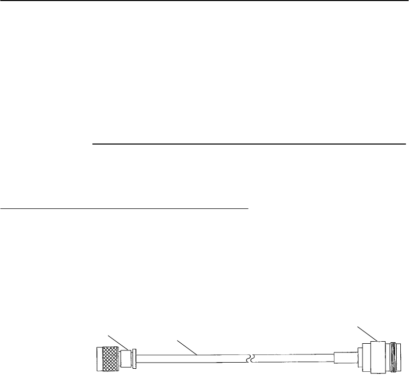
APPENDIXB"WLIFSpecificationsand Antennas
6710 Access PointUser’sGuide B-5
High GainYagi
Thehighgainyagi isalinearpolarizedantennatypically
usedin heavy rackingwheretherearelongcorridorsthat
cannotbepenetratedthroughthesideusingcollinears.
Thefollowingchartlistskitpartnumbers.
CableLengthKitPartNumber
10 feet203-423-007
20 feet203-423-008
30 feet203-423-009
AntennaAdapterCable
Theantenna adapter cable(FigureB-1)enables
INTERMECRModel110 or2100 antennastobeusedwith
the6710 Access Point.Thecable’spartnumberis
226-295-001.
Figure B-1
AntennaAdapterCable
1.RF plug (customthreaded)
2.Coaxialcable(6inches)
3.N-type connector
2
13
ConsultyourSalesRepresentativefortheregulatorystatus
andavailabilityofthispartoutside ofNorthAmerica.

APPENDIXB"WLIFSpecificationsand Antennas
B-66710 Access PointUser’sGuide
Model2100 Antennas and Cables
2.4GHzAntennas
PartNumberAntenna,2.4GHz
805-486-001 Whip(pageB-3)
066147 Omni
063363 3 dBiomni
065349 9 dBiomni
067261 3 dBiminiomni
067262 5 dBidualflat
067263 9 dBiflatpanel
2.4GHzAntennaCables and
Connectors
PartNumberDescription
226-295-001 6710 adapter cable(tocable) (pageB-5)
064616 Cable,2.5feet(76 cm)
063245 Cable,5feet(152 cm)
063246 Cable,20 feet(610 cm)
063198 Splitter
061868 Lightningsuppressorandbracket
586610 Lightningsuppressor capsule
589377 LMR400 cablepreptool
064432 LMR400 cable,100 feet
061475 TypeNpolarizedcableconnector
063146 TypeNcableconnector

6710 Access PointUser’sGuide C-1
AppendixC
900 MHzSpecifications
and Antennas
""""""""""""""""""""""""""""
RM160
Themodelnameforthe900 MHzradioisRM160,aType
III PCcard.Followingarenetworkingspecifications.
Frequencyband:902 to928 MHzspreadspectrum,
directsequence
Range:Upto1300 feetline ofsight
Coverage:100,000--350,000 squarefeetintypical
indoorinstallations
Datarate:90,225,or450 Kbps(dependson
installation)
Channelization:7@90 Kbps,1@225 or450 Kbps
Softwarecompatibility:Requirescommunicationsdriver
includedwiththe6710 Access Point
software
Outputpower:250 mW
MAC protocol: Openwireless LANMAC radioproto-
col
Optional interbuilding
wireless bridge:Yes
Operatingtemperature:--4dFto122 dF(--20 dCto50 dC)
Regulatorycompliance:FCC 15.247
IndustryCanadaRSS 210
ConsultaSales Representativefor
availability.

APPENDIXC"900 MHzSpecificationsand Antennas
C-26710 Access PointUser’sGuide
RadioOperation
Wireless deviceswiththe900 MHzoptioncanoperatein
Australia andinmostcountriesinNorthandSouth
America.ContactaSalesRepresentativefor current
informationaboutcountriesinwhichtheproductis
approvedforuseandcountriesinwhichsubmissionfortype
approval isplanned.
PartNumbers
ThefollowingchartlistsRM160 partnumbersandspecial
comments.
RM160 PartNumberCompatibility andComments
226-120-001 Kit(cable only),usedwith
219-010-001.
219-010-001
(forPCcardslot1or2)RM160 only.Usedwith226-120-001.
AntennaRegulations
For900 MHzsystems,regulationsrequiretheantenna and
antennaconnectorontheaccess point tobeuniqueandnot
commerciallyavailable.Thisensuresthat theRFoutputof
theradiostayswithinthelimits specifiedbytheregulating
agencies.
WhipAntenna
ThestandardWLIFwhipantennacanbeusedthroughout
Europe.Itspartnumberis805-472-001.

APPENDIXC"900 MHzSpecificationsand Antennas
6710 Access PointUser’sGuide C-3
RemoteAntennaKits
Remoteantennakitsallowavarietyofantenna
configurations(foraradioinstalledintheaccess point)to
belocatedupto30 feetfrom theaccess point.Contactyour
SalesRepresentativeforinformationabout theantennakit
mostsuitableforyourinstallation.
"NOTE:FCC and DOCregulationsrequirethatqualified personnel install
remote antennas.ContactyourSalesRepresentativefor more
information.
Thefollowingchartlists900 MHzradioantennakits.
AntennaKitPartNumber
3dBgain,10 ftcable203-325-001
3dBgain,20 ftcable203-325-002
3dBgain,30 ftcable203-325-003
Lowprofileceilingmount,
20 ftcable203-367-001

APPENDIXC"900 MHzSpecificationsand Antennas
C-46710 Access PointUser’sGuide

6710 Access PointUser’sGuide D-1
AppendixD
S-UHFSpecifications
and Antennas
""""""""""""""""""""""""""""
RM111
ThemodelnamefortheS-UHFradio optionisRM111,a
TypeII PCcard.Followingarenetworkingspecifications.
Frequencyband:430 to450 MHzor450 to470 MHz
Range:Upto3500 feetline ofsight
Coverage:800,000 squarefeet(72,000 square
meters)intypical indoorinstallations
Datarate19.2Kbps(14.4Kbpswithforward
error correction) (four-levelfrequency
shiftkeying)
Channelization:20 kHzor25 kHz
Transmitpower:27 dBm(.5Watts)
Receiversensitivity:--105 dBm
Outputpower:500 mW
MAC protocol: Openwireless LANMAC radio
protocol
Wireless hopcapability:No(see pageD-3)
Optional interbuilding
wireless bridge:No
Operatingtemperature:--4dFto122 dF(--20 dCto50 dC)

APPENDIXD"S-UHFSpecificationsand Antennas
D-26710 Access PointUser’sGuide
Regulatorycompliance:FCC Part90 (pending)
ETS300-220
CE 300-339 (Europe)
MPT 1329
FTZ2014
Consultalocalsales office forthe cur-
rentregulatorystatus.
RadioOperation
Wireless deviceswiththeS-UHFoptioncanoperatein
selectedcountriesinEurope,Asia(exceptJapan),
Australia,andmostcountriesinNorthandSouthAmerica.
ContactaSalesRepresentativefor currentinformation
aboutcountriesinwhichtheproductisapprovedforuse
andcountriesinwhichsubmissionfortypeapproval is
planned.
PartNumbers
Thefollowingchartlistsradiopartnumbers.
PartNumberComments
245-149-102 Kit,usedwith219-006-001 or
219-007-001.
219-006-001
(PCcardslot2only)RM111 only.Usedwith245-149-102.
Bandis450 to470 MHz.Multiple
frequencies mustbe separatedbyat
least40 KHz(20 KHzspacing)or50
KHz(25 KHzspacings).
219-007-001 (lowband)
(PCcardslot2only)RM111 only.Mustbeusedwith
245-149-002.Bandis430 to450
MHz.Multiplefrequencies mustbe
separatedbyatleast40 KHz.

APPENDIXD"S-UHFSpecificationsand Antennas
6710 Access PointUser’sGuide D-3
Wireless Hops
Because ofthelowdatarate, wireless hopsarenot
supportedforS-UHFsystems.
AntennaConnector
TheS-UHFantennausesastandardBNCconnector.
WhipAntennas
ForS-UHF,thestandardwhipantennaistheprimary
antenna.Itspartnumberis805-511-001.
Acabledexternalantennaisrequiredincaseswherethe
access pointandantennacannotbeinstalledat thesame
location.Antennas shouldbeinstalledtomaximize
separationdistancefrom metalobstructions.The
recommendedminimumseparationdistanceis19 feet(6
meters).
Thefollowingchartlistscabledexternalwhipantennas.
LengthPartNumber
5feet203-449-002
18 feet203-449-003
36 feet203-449-001
50 feet203-449-004
75 feet203-449-005
100 feet203-449-006

APPENDIXD"S-UHFSpecificationsand Antennas
D-46710 Access PointUser’sGuide
SiteLicense
OperationofS-UHFrequiresasitelicenseintheUnited
Statesandsome other countries.ConsultSales
Administration(intheUnitedStates)ortheappropriate
NationalRegulatoryAgency(outsidetheUnitedStates) for
informationabout theappropriateapplicationprocess.
Technology
S-UHFtechnology providesanextendedrangesolutionfor
installationsrequiringsmall populationsofterminal
emulationstationsoperatingatlowtransactionrates.In
regionswhere900 MHzoperationispermitted(United
States,Canada,Australia,andseveralcountriesinCentral
andSouthAmerica),S-UHFisrecommendedonlyforthe
following:
"Sitesinexcess of500,000 squarefeet(50,000 square
meters).
"Sitesrequiring10 orfewerterminalemulation
stations.
"System transactionratesless than1persecond.
S-UHFmaybeappropriateforlargersitesonanindividual
basis.ConsultyourSalesRepresentativeformore
information.
Transaction Rates
S-UHFperformanceis sensitivetotransactionrateand
terminalcount.Theinstallationguidelineis32 orfewer
wireless stationsperfrequency.Thefollowingchartshows
guidelinesformultiplefrequencyinstallations.

APPENDIXD"S-UHFSpecificationsand Antennas
6710 Access PointUser’sGuide D-5
#Frequencies#Wireless Stations
1 32
2 60
3 80
4 100
Installation Guidelines
Thefollowingpagescontainguidelinesforpredictingthe
coveragearea andinstallingsingleandmultipleaccess
points.
Predicting Coverage
TableD-1showspredictedindoor coverageareasforan
access pointwiththeS-UHFradio.Thetablewas
generatedusingamathematicalmode.Areasareinsquare
meters.Forsquarefeet,multiplytheareainsquaremeters
by10.
TableD-1
CoveragePrediction
IncreasedCoverageOverlapBetween
Access PointsÞ Þ Þ
Increasedobstructions120K*100K80K64K
ß100K84K** 64K** 51K
ß82K68K** 52K** 42K
ß68K56K43K34K*
*The extremes of120Kand 34Ksquare meters are indicative
ofbestand worstcase coverage resultsusingthismodel.
** Reflectstypicalexpectedcoverageforindustrialand ware-
housingapplications.

APPENDIXD"S-UHFSpecificationsand Antennas
D-66710 Access PointUser’sGuide
Installing aSingleAccess Point
Youcaninstall asingleaccess pointwhenwireless station
populations,system transactionrates,andcoverage
requirementspermit.Followingaresomefactorsto
consider:
"Forlargecoverageareas,itisnecessarytolocatethe
access pointoptimallytomaximizecoverage.
"Atsiteswherethestructureandoperationswithin
provideauniformRFsignalpropagationenvironment,
thelocationisgenerallycentralizedwithinthefacility.
"Fornonuniformsites,thelocation needstobeadjusted
forbestcoverage.
"Forsmall sites,locationisless criticalandmaybe
adjustedtominimizeLANwiring.
LocationofS-UHFaccess pointswithincomputer roomsis
notrecommended,becauseRFemissionsfrom thehigher
speed processorsusedincurrentgenerationcomputersmay
reducesystemrange.
Installing MultipleAccess Points
Multipleaccess pointscanextendcoverage,reusea
frequency,andincreasesystem throughput.
Extending Coverage
Multipleaccess pointsmaybeinstalledto extendcoverage.
FigureD-1showsaninstallationwheremaximizing
coverageisthemainobjective.
"NOTE:Asitesurveyisrequired forthistype ofinstallation.
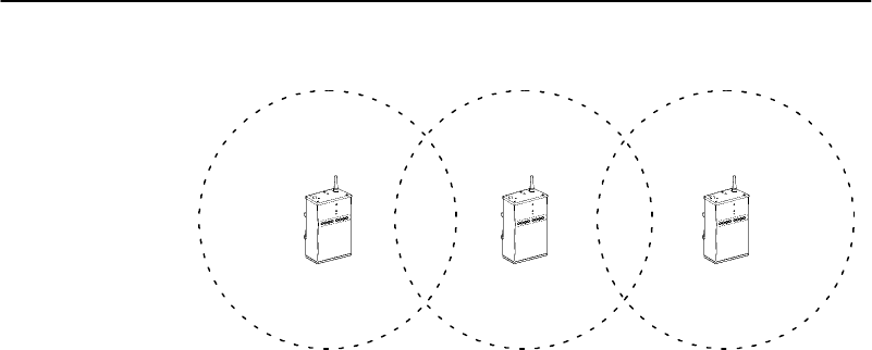
APPENDIXD"S-UHFSpecificationsand Antennas
6710 Access PointUser’sGuide D-7
Figure D-1
Extending Coverage
Inthistype ofinstallation,theaccess pointcoverageareas
are overlappedminimallytoprovideseamless coverage.
Theaccess pointsmayall useacommonfrequency,
requiringadherencetothesystem terminalpopulationand
transactionratelimitsforonefrequency.
Youcanalsoinstall access pointsondifferentfrequencies.
Inthiscase,youmaybeabletoincreasethewireless
stationpopulationandtransactionrate.However,the
singlefrequencywireless stationpopulationand
transactionratemustbemaintained peraccess point.The
installationmustconsiderwhetherthesystem mayatany
timeberequiredto operatewithmorethanthemaximum
numberofwireless stationsinanyoneaccess point
coveragearea.
Reusing theFrequency
Ifaccess pointsareseparatedbysufficientdistance,you
canreuseafrequency,asillustratedinFigureD-2.
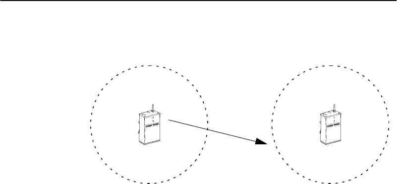
APPENDIXD"S-UHFSpecificationsand Antennas
D-86710 Access PointUser’sGuide
"NOTE:Asitesurveyisrequired forthistype ofinstallation.
Figure D-2
Frequency Reuse
Access PointA Access PointB
--105 dBm
Inthistype ofinstallation,youcaninstall access pointson
thesamefrequency.Eachaccess pointcansustainthe
singlefrequencywireless stationpopulationand
transactionrate.Theguidelineforfrequencyreuseis:
Thesignal levelproducedbyaccess point “A” mustbe
less than--105 dBmat therequiredcoveragelimitof
access point “B.”
Increasing SystemThroughput
Toincreasethewireless stationpopulationorsystem
transactionrate,youcanoverlapaccess pointcoverage
areasandusemultiplefrequencies.Thesystemdesign
allowsuptofourfrequencies,100 stations,andthree
transactionspersecond.Largewireless stationpopulations
ortransactionratesrequireuse ofone ofthehighspeedRF
media.

APPENDIXD"S-UHFSpecificationsand Antennas
6710 Access PointUser’sGuide D-9
Twoconfigurationoptionsarepossible:
Option1:Configurewireless stationsforfrequencyagile
operation.
Option2:Configurewireless stationsforsinglefrequen-
cyoperation,splittingthewireless station
populationequallyamongtheavailablefre-
quencies.
Bothoptionsrequirethatyouconfiguretheaccess pointson
uniquefrequencies.
Option 1
Option1isrecommendedwhenthesystemcannotbe
installedsothateachaccess pointcoversthe entirearea.
Inthiscase,youmustinstall theaccess points sothatall of
themoverlapin high usageareawherewireless station
populationsandtransactionratesaregreatest.
Frequencyagilesoftwareinthewireless stationsallows
roamingbetweenfrequencies.Thewireless stationsemploy
aloadbalancingalgorithmsothat thenumberofwireless
stationsoneachfrequencyisabout thesameatall times.
If frequencyagilityisused,andthewireless stationsare
normallypoweredupinanareaofoverlappingcoverage,
youcanspeedupnetworkattachmentbysettingdifferent
defaultfrequenciesinthewireless stationsforinitial load
balancing.This shortenstheperiodrequiredfortheload
balancingalgorithm toadjust.
Option 2
Option2isrecommendedifthecoverageareais small
enoughthatall access pointscanbeinstalledtocoverthe
full area.See FigureD-3.
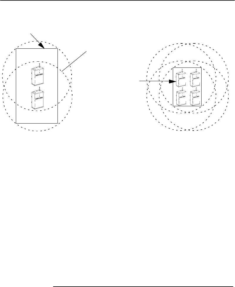
APPENDIXD"S-UHFSpecificationsand Antennas
D-10 6710 Access PointUser’sGuide
Figure D-3
IncreasedSystemThroughput
32 orfewerwireless
stationsinthis area
60 wireless stationsmaxi-
mumin overlaparea (two
frequencies)
100 wireless stations
maximumin overlap
area (fourfrequencies)
Frequency and Separation Guidelines
When usingoverlappingaccess points,youmustprovide
minimumphysicalseparationbetweenaccess point
antennas.Therecommendedminimumfrequency
separationbetweenfrequenciesusedwithinaninstallation
is200 KHz, withseparationof1MHzpreferred.
Insomecases,youmayneedtouseseparationsas small as
40 KHz(for20 KHzspacings)or50 KHz(for25 KHz
spacings)because ofregulatorylimitations.Inthiscase,
thephysicalseparationbetweenaccess pointantennas
mustbeincreased.Therecommendedminimumphysical
separationbetweenaccess pointsis30 meters(100 feet).
Absoluteminimumseparationsarebasedonfrequency
separation,asindicatedinthefollowingchart.
FrequencySeparationAbsoluteMinimum
50 KHz100 feet(30 meters)
³200 KHz20 feet(7meters)

6710 Access PointUser’sGuide E-1
AppendixE
OWL/IP
""""""""""""""""""""""""""""
Introduction
Wireless networksmaybeinstalledinenvironmentsthat
aresegmentedbyIProuters.IfOWL/IPisnotenabled,the
presence ofaroutergenerallydefinesthephysical
boundaryofthewireless network.Wireless coveragecanbe
providedbyinstallingmultipleindependentwireless
networks,eachwithitsownLANID, super rootandsetof
wireless stations.Inthisenvironment,stationscanonly
operatewithinthelimitedcoverageareaofitsown network
andcannotroamacross subnetboundaries. OWL/IP
providesthecapabilityofinstallingasingle,extended
wireless systemintheroutedenvironment.
OWL/IPprovides:
"Extensionofthe openwireless LANspanningtree to
includeaccess pointsoperatingondifferentIP
networksorsubnetworks.
"Transparentroamingofwireless stationsacross router
boundarieswithoutloss ofconnectivity.
"Supportofwireless stationsusingbothIPand
ordinarilynonroutableprotocols.

APPENDIX E "OWL/IP
E-26710 Access PointUser’sGuide
OWL/IPisactivatedbyenablingtheOWL/IPportinthe
access point.TheportisanentrywaytoanIPtunnel
originatedbythesuper rootonthehome subnet,and
terminatedbyadesignatedbridge operatingonaremote
subnet.Framesare encapsulatedusingtheGRE protocol
runningoverIP.
Thesuper rootcanoriginateIPtunnelsto eightorfewerIP
addresses.Thenumberoftunnels supportedmaybemore
thanorfewerthaneight,dependingonthetype of
addressingusedandredundancyneedswithinthe
installation.
TheOWL/IPportdiffersfrom thephysical NIC1,NIC2 and
Ethernetportswithintheaccess point.Itisalogicalport
thatprovidesIPencapsulationservicesforframesthat
mustberoutedtoreachtheirdestination. Once
encapsulated,framesaretransmittedor receivedthrough
one ofthethree physicalports.
OWL/IPRestrictions
Addressing Limitations
Wireless stationsusingIPmustbeassignedIPaddresses
onthehomesubnet.Serversmaybelocatedonanysubnet.
However,itispreferabletochoosethesubnet thatcontains
serversforwireless stationsasthehomesubnetifpossible.
Installation Limitations
OWL/IPtunnels shouldnotbeused:

APPENDIX E "OWL/IP
6710 Access PointUser’sGuide E-3
"FornetworkprotocolsthatanIProuterisconfigured
tobridge.Manyroutersmaybeinstalledtobridge
specificframetypes.Theseroutersare oftenreferred
toasB-routers.
"Fornetworkprotocolsarouteriscapable ofrouting.
Forexample,IPXframes shouldnotbetunneled
througharouter capable ofroutingbothIPandIPX
frames.
Ifaccess pointsareinstalledsothatawireless secondary
LANcanbe establishedbetweenaccess points separatedby
arouter,itispossibletoinadvertentlybridgearoundthe
router.Thiscanbeavoidedbychoosingdesignatedbridge
locations,or choosingradiochannelstoavoidinadvertent
wireless bridging.
OWL/IP Safeguards
Thepurpose ofarouteristosegment trafficonalocal
network,andselectivelyforwardframesdestinedto
addressesonothernetworks. OWL/IPisdesignedto
minimizetheimpactonexistinginstallations, while
supportingmobilityforwireless stations.Thesafeguards
onthefollowingpagesarebuiltintoOWL/IP.
DefaultSettings
Bydefault, OWL/IPisdisabledandmustbemanually
enabledbeforetunnelsare originated.Additionally,once
enabled,defaultfiltersettingspreventforwardingofall
protocolsexceptNORANDNetworkLayer(NNL),ARPfor
IPaddress resolution,andICMP, whichsupportsdiagnostic
capabilities suchasPING. Extensivefilteringcapabilities
areprovidedtoallowtraffictoberestrictedtothatknown
tobedestinedtowireless stations.

APPENDIX E "OWL/IP
E-46710 Access PointUser’sGuide
Addressing Limitations and
Flooding Restrictions
Wireless stationsusingIPmustbeassignedaddresseson
thehomesubnet.TheARPserver capabilitycanbe enabled
toreducepropagationofARPsthroughtunnels.IPservers
canbelocatedonanysubnet;however,itisdesirableto
choosethesubnetcontainingserversusedextensivelyby
clientwireless stationsasthehomesubnetifpossible.
ForstationsorserversusingprotocolsotherthanIP,there
arenorestrictionsonlocationofserversoraddress
assignments.Routingisminimizedifserversarelocatedon
thehomesubnet.
OWL/IPdoesnotfloodoutboundunicastframes.Multicast
IPframesareforwardedoutboundfrom thehomesubnet.
Designatedbridgesforwardunicastandmulticastframes
inboundtothehomesubnetiftheIPaddress belongstothe
homesubnet.(See “SubnetFiltering,”pageE-6.)Global
FloodingsettingsandFloodRegistersettingsdonotapply
toOWL/IPtunnels.
PermanentFilters
Certainframetypesareneverforwardedthroughtunnels.
TheseincludethoseIPprotocolsusedfor coordinating
routers,or MAC framesusedfor coordinatingbridges.
Theseframesarenotforwarded:
"802.1dbridgeframes.
"IPframeswitha broadcastormulticastEthernet
address.
"IPframeswiththefollowing(router)protocoltypes
and decimalvalues:

APPENDIX E "OWL/IP
6710 Access PointUser’sGuide E-5
DGP(86) (DissimilarGatewayProtocol)
EGP(8) (ExteriorGatewayProtocol)
IDPR(35) (Inter-DomainPolicyRoutingProtocol)
IDRP(45) (Inter-DomainRoutingProtocol)
IGP(9) (InteriorGatewayProtocol)
IGRP(88) (InteriorGatewayRoutingProtocol)
MHRP(48) (MobileHostRoutingProtocol)
OSPFIGP(89) (OpenShortestPathFirstInterior
GatewayProtocol)
"IPICMPtypes,including:
IPv6
MobileIP
RouterAdvertisement
RouterSelection
"IP/UDPframeswiththesedestinationprotocolport
numbers:
BGP(179) (BorderGatewayProtocol)
RAP(38) (RouteAccess Protocol)
RIP(520) (RoutingInformationProtocol)
"IP/TCPframeswiththesedestinationorsource
protocolportnumbers:
BGP(179) (BorderGatewayProtocol)
RAP(38) (RouteAccess Protocol)
Theseframesarealwaysforwarded:
"DIX0875Copenwireless LAN inter-access point
coordinationframes
"DIX0800 InternetProtocol
"IP Protocol(47)GRE

APPENDIX E "OWL/IP
E-66710 Access PointUser’sGuide
DefaultFilterSettings
Thedefaultsettingsfor[TXFilter]areset topass the
followingframetypes(and dropall others):
"DIX0875BNNL
"DIX0806 ARP
"IP ProtocolICMP(1)supportingthefollowingframe
types:
Address MaskReply(18)
Address MaskRequest(17)
AlternateHostAddress (6)
DestinationUnreachable(3)
EchoReply(0)
EchoRequest(8)
ParameterProblem(12)
Redirect(5)
SourceQuench(4)
TimeExceeded(11)
TimeStamp(13)
TimeStampReply(14)
TraceRoute(30)
SubnetFiltering
OWL/IPautomaticallyprovides subnetfilteringforIP
wireless stations. Designatedbridgesneverforwardframes
tothehomesubnet,unless theIPaddress belongstothe
homesubnet.Thisfeaturepreventsinboundfloodingof
undesiredIPtraffic.

APPENDIX E "OWL/IP
6710 Access PointUser’sGuide E-7
PasswordSecurity
Theaccess pointhastwolevelsofpasswordsecurity.
Knowledge ofthestandard passwordallowsgeneralaccess
totheconfigurationmenus.Ifdesired,theOWL/IP
configurationcanbeaccess protectedbyenablingthe
AdvancedPasswordinthe[Security]menu.
Operation
OWL/IPusesIPencapsulationto establishavirtualLAN
segment throughanIProuter.TheOWL/IPtunnel
becomesa branchinthespanningtree.Access pointson
theremotesubnetarelinkedtothesuper root througha
designatedbridge. Operationisanalogoustosecondary
LANs, wherewireless linksareusedtoconnectEthernet
segments.FigureE-1showsEthernetsegmentsconnected
byawireless link;FigureE-2showsanOWL/IPtunnel.
ForEthernetsecondaryLANs,awireless linkisestablished
betweenanaccess pointonthedistributionLANanda
designatedbridge onasecondaryEthernetsegment.
Framesto orfromasecondaryEthernetLANarebridgedat
theMAC layer.Inthecase ofOWL/IP,avirtualMAC layer
linkisestablishedthroughan“IPtunnel”betweenthe
super rootandadesignatedbridge.
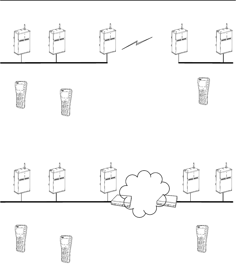
APPENDIX E "OWL/IP
E-86710 Access PointUser’sGuide
Wireless Station
Figure E-1
SecondaryLAN
AP3
(Designated
Bridge)
Distribution LAN
Wireless LinkAP1AP2
(Super
Root)
AP4
AP5
Wireless Station Wireless Station
SecondaryLAN
Wireless Station
Figure E-2
OWL/IPTunnel
AP3
(Designated
Bridge)
Distribution LAN
HomeSubnet
AP2
AP1
(Super
Root)
AP4
AP5
Wireless Station
Wireless Station
SecondaryLAN
RemoteSubnet
IPNetwork
IPRouterIPRouter

APPENDIX E "OWL/IP
6710 Access PointUser’sGuide E-9
Followingarethree primarydifferencesbetweensecondary
LANs separatedbywireless linksandsecondaryLANs
separatedbyOWL/IPtunnels:
"Anyaccess pointonthedistributionLANcanprovide
wireless connectivityforadesignatedbridge ona
secondaryEthernetLAN. Onlythesuper rootcan
originateOWL/IPconnectionstodesignatedbridges
onremotesubnets.
"Floodingparametersfordesignatedbridgeson
secondaryEthernetLANscanbeadjustedthroughthe
globalsettingsinthesuper root,orthroughlocal
configurationinthedesignatedbridge.Flooding
parametersforOWL/IPtunnelsarenotadjustable.
"Thesuper rootand designatedbridgesforOWL/IP
tunnelsincludeadditionalconfigurable output
(transmit) filters,allowingframetypesforwarded
throughtunnelstobetightlycontrolled.Thesefilters
areprovidedinadditiontothestandardEthernet
inputfiltersavailableinall access points.
TunnelOrigination
Building theSpanning Tree
The openwireless LANspanningtree isestablishedand
maintainedbyshorthellomessagesoriginatingat thesuper
root.“Hellos”arebroadcastperiodicallyatintervalsofa
fewseconds.Theseframescontain networkcoordination
information,includingrootpriority.
Atpowerup,all super rootcandidateslistenforhello
messages.Iftheydonotdetecthellos,ordetecthellosfrom
alowerpriorityrootcandidate,theybegintosendhello
messages.

APPENDIX E "OWL/IP
E-10 6710 Access PointUser’sGuide
Ifasuper rootcandidatereceivesahellofromanaccess
pointwithahigher rootpriority(orequalrootpriorityfrom
ahigher MAC address),itstops sendinghellos.Thisroot
electionprotocolcontinuesuntil onlyonesuper rootaccess
pointsendshellos.Afterthesuper rootisestablished,other
access pointsattachtothesuper rootformingthespanning
tree.
Establishing and Maintaining Tunnels
Onceasuper rootiselected,itbeginstoforwardhello
messagestoIPaddressesconfiguredintheOWL/IPmenu.
Designatedbridgecandidatesonaremotesubnetuse
bridgepriorityinasimilarelectionproceduretodetermine
whichaccess pointservesasdesignatedbridgeforthat
subnet.
Onceadesignatedbridgeiselected,itattachestothesuper
root,indicatingthatitisthedesignatedbridgeforthe
subnet. Designatedbridgesareresponsibleforforwarding
hellosto otheraccess pointsonthelocalsubnets.These
hellosindicateto otheraccess pointsthat theyarethe
designatedbridgeforthatsubnet.
Redundancy
Thesuper rootand designatedbridge electionprocedureare
repeatedifthecurrentsuper rootordesignatedbridgestops
sendinghellos.Thisprovidesredundancyinthe eventofan
isolatedaccess point,router,power,or cablingfailure.
Normally,oneprimaryandone ortwofallbacksuper root
candidatesaresufficientforsuper rootredundancy. One
primarydesignatedbridgeandonefallbackarerecommend
formostremotesubnetinstallations.Thenumberof
remotesubnetsandredundancyneedsoneachsubnet
influencestheselectionofaddress typesinthe[IP
Addresses]menu.See theconfigurationexamplesonpage
E-13.

APPENDIX E "OWL/IP
6710 Access PointUser’sGuide E-11
FrameForwarding
MAC framesoriginatingonthehomesubnetare
encapsulatedinthesuper root,forwardedthroughtheIP
network,deencapsulatedinthedesignatedbridge,and
forwardedtotheappropriateaccess pointfordeliverytothe
intendedwireless station.Thesameprocess isusedin
reversebetweenthedesignatedbridgeandthesuper root
forinboundframes.The encapsulation usesthestandard
IPGRE protocol.
Outbound
DataframesareforwardedoutboundthroughanIPtunnel
if:
"Awireless stationisknowntobeattachedtoanaccess
pointonaparticular remotesubnet.
"Theframetypeis specifiedinthe[TXFilter]menu.
Designatedbridgesareresponsibleforforwardingattach
statusforwireless stationstothesuper root.Thesuper
root maintainsentriesforthesestationsinitsforwarding
databaseindicatingthecorrectsubnetforoutbound
forwarding.
IPARP(Address ResolutionProtocol)andICMPframesare
normallyforwardedoutboundthroughall tunnels.
EnablingtheARPserverinthesuper rootcanreducethe
numberofARPsforwarded.
Inbound
Thesameforwardingrulesapplyforframesinboundfrom
remotesubnets. Designatedbridgesmaintainentriesin
theirforwardingdatabaseforaddressesthatrequire
routingthroughtunnels.
Framesdestinedforserversorstationsonthelocalsubnet
arenotforwardedthroughtunnels. Onlyframetypes
configuredinthe[TXFilter]menu areforwarded.

APPENDIX E "OWL/IP
E-12 6710 Access PointUser’sGuide
Additionally,IPframesare onlyforwardedinboundiftheIP
address belongstothehomesubnet(see “SubnetFiltering,”
pageE-6).
Station Mobility
As stationsmovethroughafacility,theyroambetween
access pointcoverageareas.Inlargeinstallations,these
access pointsmaybe ondifferentIPsubnets. OWL/IPis
designedtosupportrapidroaminginthese environments.
A“roam” requiresupdatestotheforwardingdatabasesin
thenewaccess point,super root,previousaccess point,and
anyintermediatedesignatedbridges.
Aroamisinitiatedwhenastationattachestoanewaccess
point.Thisaccess pointsendsanattachmessagetothe
super root, whichinturnforwardsadetachmessagetothe
previousaccess point,allowingeachaccess point toupdate
itsforwardingdatabase. Designatedbridgesmonitorthese
exchangesandupdatetheirforwardingdatabases.
MobileIPComparison
TheInternetEngineeringTaskForcehasdevelopedRFC
2002,IPMobilitySupport,commonlyreferredtoasMobile
IP.MobileIPisdesigned primarilytoaddress theneedsof
IPstationsthat maymovebetweengeographically
separatedlocations.
OWL/IPisdesigned primarilyto operateinlocalarea
environments, wherehandcarriedorvehiclemounted
stationsmaymoverapidlybetweenaccess pointcoverage
areasonasubnettedLAN.Thetwotechnologiesare
complimentaryandmaycoexist.TableE-1summarizes
somedifferences.

APPENDIX E "OWL/IP
6710 Access PointUser’sGuide E-13
TableE-1
MobileIPComparison
ComparisonMobileIPOWL/IP
Softwarecompatibility:RequiresaMobileIP
clientsoftwarestackin
IPwireless stations.
Allowsuse ofexistingIP
softwarestacksinwireless
stations.
Addressinglimitations
forIPstations:None.RequiresthatIPstation
addressesbelongtothehome
subnet.
Routingofnon-IP
protocols:Isnotallowed.Isconfigurablethrough
[TXFilter].Limitationsare
detailedunder“OWL/IP
Restrictions,”pageE-2.
Scalability:Hasnoinherentlimita-
tions.Limitstunneloriginationto
eightIPaddresses.The
numberofremotesubnets
supportedmaybemorethan
orfewerthaneight,depend-
ingontheselectedaddress-
ingapproach.
Specialnetworksoft-
ware:Requireshomeand
foreignagentslocatedon
each networkorsubnet-
work.
Isastandardfeatureinopen
wireless LANsystemsoft-
ware.
OWL/IPConfiguration Examples
Example 1:Class CIPAddresses
ThesamplenetworkinFigureE-3illustratesOWL/IPsetup
foralocationwithseveralClass CIPaddresses.Subnet
addressingisnotused.Forillustrativepurposes,IP
addresseshavebeenselectedfrom thoseallocatedfor
privatenetworksthatarenotconnectedtotheInternet.
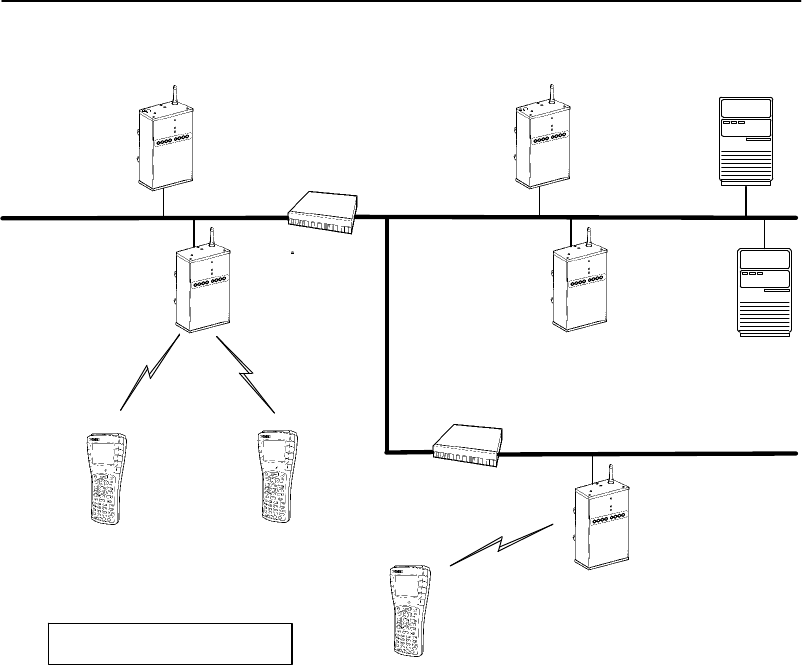
APPENDIX E "OWL/IP
E-14 6710 Access PointUser’sGuide
Figure E-3
ExampleClass C Configuration
AP1
(SuperRoot)
192.168.15.101
AP3
192.168.17.188
IP Station
192.168.15.227 NNLStation
IPRouter
Serverfor
IP Stations
192.168.15.17
192.168.15.1192.168.17.1
IPRouterAP5
(DesignatedBridge)
192.168.23.21
AP2
192.168.15.36
HomeSubnet
192.168.23.1
AP4
(DesignatedBridge)
192.168.17.16
IP Station
192.168.15.228
Serverfor
NNLStations
SubnetMask:255.255.255.0

APPENDIX E "OWL/IP
6710 Access PointUser’sGuide E-15
Step1
"Access pointsareassignedIPaddressesforthe
appropriatesubnets.
"Subnet192.168.15.0isdesignatedasthehomesubnet,
sinceitcontainstheserversusedbywireless stations.
"Wireless stationsthatrequireIPconnectivityare
givenIPaddressesonthis subnet.
"Access point(AP)1is selectedastheprimarysuper
rootandassignedrootpriority3.
"AP2is selectedasthefallbacksuper rootand
assignedrootpriority1.
"All otheraccess pointsareconfiguredtorootpriority
0.
Step2
"AP4is selectedasthedesignatedbridgeforsubnet
192.168.17.0 andconfiguredwithbridgepriority2.
"AP3isconfiguredasthefallbackdesignatedbridge
forthatsubnet,andconfiguredwithbridgepriority1.
"Otheraccess pointsonthesubnetareconfiguredwith
bridgepriority0.
"AP5ischosenasthedesignatedbridgeforsubnet
192.168.23.21.
Step3
Thetwosuper rootcandidatesareconfiguredto originate
tunnels.Two optionsareavailable:unicastaddressingand
directedbroadcast.

APPENDIX E "OWL/IP
E-16 6710 Access PointUser’sGuide
Option A:UnicastAddressing
Inthisexample,unicastIPaddressesare enteredinthe
tableforeachdesignatedbridge.Thetwodesignated
bridgesonsubnet192.168.17.0negotiatewhichaccess point
servesasthedesignatedbridgeforthatsubnet.
AP4hasthehighestbridgepriority,soAP3 becomesthe
designatedbridge onlyifAP4failsorlosesitsnetwork
connection.AP5isthe onlyaccess pointonsubnet
192.168.23.0,sonofallbackisavailable.
FollowingistheIPAddressesTableforthisoption:
Type Address
1 <Unicast> 192.168.17.16
2 <Unicast> 192.168.17.188
3 <Unicast> 192.168.23.21
4 <Unicast> 0.0.0.0
5 <Unicast> 0.0.0.0
6 <Unicast> 0.0.0.0
7 <Unicast> 0.0.0.0
8 <Unicast> 0.0.0.0
Option B:DirectedBroadcast
Inthisexample,adirectedbroadcastaddress isusedfor
eachsubnet.Thebroadcast tosubnet192.168.17.0is
receivedbyall access points.Theaccess pointwiththe
highestbridgepriorityprovidestheremoteterminationof
theOWL/IPtunnel.AbroadcastMAC address isused.
FollowingistheIPAddressesTableforthisoption:

APPENDIX E "OWL/IP
6710 Access PointUser’sGuide E-17
Type Address
1 <Broadcast> 192.168.17.255
2 <Broadcast> 192.168.23.255
3 <Unicast> 0.0.0.0
4 <Unicast> 0.0.0.0
5 <Unicast> 0.0.0.0
6 <Unicast> 0.0.0.0
7 <Unicast> 0.0.0.0
8 <Unicast> 0.0.0.0
Step4:SetTXFilters
SupportforbothNNLandIPstationsisrequired.This
exampleassumesDIXEthernetis supported,but802.3 and
SNAParenotrequired.NNLisenabledbythedefault
settings.Followingisthe[FrameTypes]screen:
Action Scope
DIX-IP-Other Protocols <Drop> <Unlisted>
Followingisthe[SubTypes1]screen:
Action SubType Value
NNL <Pass> <DIX-EtherType> 87 5b
ThedefaultsettingsforIPprotocolsenableARPandICMP.
TCPandUDParedisabledbydefault.Applications
runningoverTCPorUDPcanbe enabledbychangingthe
DIXTCPandDIXUDPportstopass all frames.Following
isthe[FrameTypes]screen:
Action Scope
DIX-IP-TCP Ports <Pass> <All>
DIX-IP-UDP Ports <Pass> <All>

APPENDIX E "OWL/IP
E-18 6710 Access PointUser’sGuide
Alternatively,ifalimitedsetofknownapplicationsistobe
supported,filtersmaybeset toselectivelypass listedPort
numbers.Followingisthe[FrameTypes]screen:
Action Scope
DIX-IP-TCP Ports <Drop> <Unlisted>
DIX-IP-UDP Ports <Drop> <Unlisted>
Forexample,tosupportFTP (data andcontrol)andTelnet,
enableprotocolports20,21,and23,respectively.
TheaboveIPportnumbersarespecifiedasdecimalvalues.
Thesecanbeinputdirectlybyfollowingthe entrywitha
decimalpoint;forexample,“20.”Valuesaredisplayedin
thetableashexadecimalvalues:14,15,and17.
Followingisthe[SubTypes1]screen:
Action SubType Value
DIX-ARP <Pass> <DIX-EtherType> 08 06
SNAP-ARP <Drop> <SNAP-EtherType> 08 06
802.2-IPX-RIP <Drop> <802.2-IPX-Socket> 04 51
802.2-IPX-SAP <Drop> <802.2-IPX-Socket> 04 53
NNL <Pass> <DIX-EtherType> 87 5b
NETBIOS <Drop> <802.2-SAP> f0 f0
1 <Pass> <DIX-IP-Protocol> 00 01
2 <Pass> <DIX-IP-TCP-Port> 00 14
3 <Pass> <DIX-IP-TCP-Port> 00 15
4 <Pass> <DIX-IP-TCP-Port> 00 17
.
.
16 <Drop> <DIX-IP-TCP-Port> 00 00

APPENDIX E "OWL/IP
6710 Access PointUser’sGuide E-19
Example 2:Class BIPAddress
Using Subnetting
The exampleinFigureE-4usestheClass Baddress of
172.16.0.0 andasubnet maskof255.255.248.0.This
provides30 subnetsof2046 hostseach.Subnetaddressing
forthisnetworkisdescribedunder“IPSubnetMask”in
Section4,“Configuration.”
Inthisexample,eachsubnethasabout10 access points.
Thehomesubnetcontainstheaddress range of172.16.16.1
through172.16.23.254.
Step1
"Access pointsareassignedIPaddressesforthe
appropriatesubnets.
"Subnet172.16.16.0isdesignatedasthehomesubnet,
sinceitcontainstheserversusedbywireless stations.
"Wireless stationsthatrequireIPconnectivityare
givenIPaddressesonthis subnet.
"AP1is selectedastheprimarysuper root,andgiven
rootpriority3.
"AP2is selectedasthefallbacksuper rootand
assignedrootpriority1.
"All otheraccess pointsareconfiguredtorootpriority
0.
Step2
"AP11 is selectedasthedesignatedbridgeforsubnet
192.16.24.0 andconfiguredwithbridgepriority2.
"AP12 isconfiguredasthefallbackdesignatedbridge
forthatsubnet,andconfiguredwithbridgepriority1.
"Otheraccess pointsonthesubnetareconfiguredwith
bridgepriority0.
"AP21 andAP22,AP31 andAP32,etc.areconfigured
asdesignatedbridgecandidatesfortheir respective
subnets.
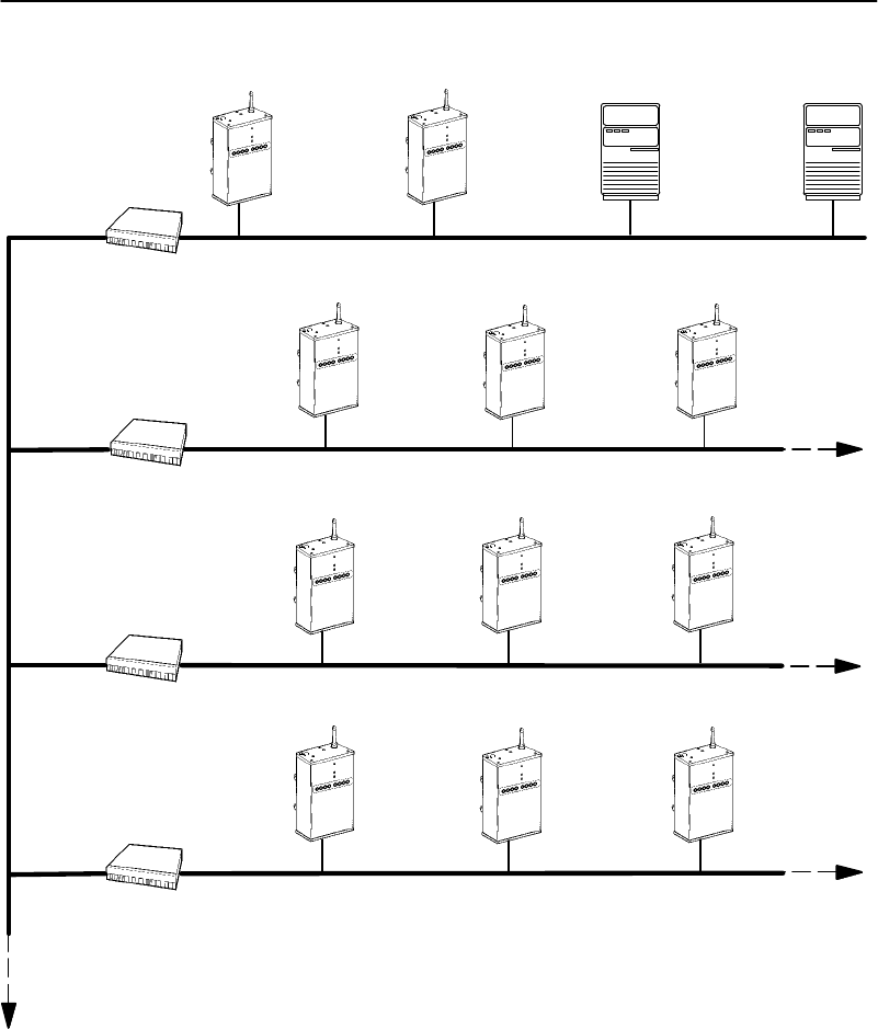
APPENDIX E "OWL/IP
E-20 6710 Access PointUser’sGuide
Figure E-4
ExampleClass B Configuration
AP1
(SuperRoot)
172.16.16.101
172.16.8.1
IPRouter
Serverfor
IP Stations
172.16.23.141
172.16.16.1HomeSubnet
Serverfor
NNLStations
AP2
172.16.19.36
172.16.8.2
IPRouter172.16.32.1
AP12
172.16.32.3
AP11
172.16.32.2AP13
172.16.32.4
172.16.8.3
IPRouter172.16.40.1
AP22
172.16.40.3
AP21
172.16.40.2AP23
172.16.40.4
172.16.8.4
IPRouter172.16.48.1
AP32
172.16.48.3
AP31
172.16.48.2AP33
172.16.48.4

APPENDIX E "OWL/IP
6710 Access PointUser’sGuide E-21
Step3
Thetwosuper rootcandidatesareconfiguredto originate
tunnels.
Option A:UnicastAddressing
Inthisexample,unicastIPaddressesare enteredinthe
tableforeachdesignatedbridge.Thetwodesignated
bridgesoneachsubnetwill negotiatewhichaccess point
servesasthedesignatedbridgeforthatsubnet.
Use oftwodesignatedbridgecandidatesoneachsubnet
restrictsthenumberofsubnetsthatcanbesupportedto
four.Toincreasethesize ofthewireless network,itis
necessaryto eliminateredundantdesignatedbridgesoruse
broadcastaddressing.
Type Address
1 <Unicast> 172.16.24.2
2 <Unicast> 172.16.24.3
3 <Unicast> 172.16.32.2
4 <Unicast> 172.16.32.3
5 <Unicast> 172.16.40.2
6 <Unicast> 172.16.40.3
7 <Unicast> 172.16.48.2
8 <Unicast> 172.16.48.3
Option B:DirectedBroadcast
Inthisexample,adirectedbroadcastaddress isusedfor
eachsubnet.Thebroadcast toaddress 172.16.23.255 is
receivedbyall access pointsonsubnet172.16.16.0.The
access pointwiththehighestbridgepriorityprovidesthe
remoteterminationoftheOWL/IPtunnelforeachsubnet.
AbroadcastMAC address isused.Thisoptionsupports
primaryandfallbackaccess pointson upto eightsubnets.

APPENDIX E "OWL/IP
E-22 6710 Access PointUser’sGuide
Type Address
1 <Broadcast> 172.16.23.255
2 <Broadcast> 172.16.31.255
3 <Broadcast> 172.16.39.255
4 <Broadcast> 172.16.47.255
5 <Unicast> 0.0.0.0
6 <Unicast> 0.0.0.0
7 <Unicast> 0.0.0.0
8 <Unicast> 0.0.0.0
Option C:All SubnetsBroadcast
Inthisexample,anAll Subnetsbroadcastaddress isused.
Thisbroadcastisforwardedthroughout thenetworkand
receivedbydesignatedbridgesonall subnets.See
CommentsonthenextpagebeforeusingtheAll Subnets
broadcast. Directedbroadcastisthepreferred
implementationforlargersysteminstallations.
Type Address
1 <Broadcast> 172.16.248.255
2 <Unicast> 0.0.0.0
3 <Unicast> 0.0.0.0
4 <Unicast> 0.0.0.0
5 <Unicast> 0.0.0.0
6 <Unicast> 0.0.0.0
7 <Unicast> 0.0.0.0
8 <Unicast> 0.0.0.0

APPENDIX E "OWL/IP
6710 Access PointUser’sGuide E-23
Comments:
"TheAll Subnetsbroadcastgeneratestraffictoall
subnets,includingthosethatdonotcontainaccess
points.
"SomeIProutersdonotsupportAll Subnets,ormay
requirespecific configuration.
"Therearepractical limitsonthenumberoftunnelsa
super rootcanestablishandsupport.Theselimits
dependonfactorsuniqueto eachinstallation,suchas
networktraffic.The eight tunneladdresses specified
inthemenu areaconservativelimitforlarge
networks.
"Generally,installationsthatrequireroamingover
multiplesubnetscanbepartitionedinotherways.
ConsultyourSalesRepresentative orTechnical
Supportformoreinformation.
Step4
TXfiltersetupisidenticaltoExample1(pageE-13).

APPENDIX E "OWL/IP
E-24 6710 Access PointUser’sGuide

6710 Access PointUser’sGuide F-1
AppendixF
Portand CablePin-Outs
""""""""""""""""""""""""""""
Thisappendixlistspin-outsforthe6710 Access Point’s
DIAGandAUIports,andthestandardnull modemcable.
DIAGPortPin-Outs
Thefollowingchartdefinesthesignalspresentonthepins
fortheDIAGport.Pin numberingisfromleft torightand
toptobottom.Forexample,pin1isonthetopleftofthe
connector,andthelastpinisonthebottomright.
PinNumberSignalNameSignalLevel
1Notused
2TXDRS-232
3RXDRS-232
4DTR RS-232
5GND
6DSR RS-232
7Notused
8Notused
9Notused

APPENDIXF"Portand CablePin-Outs
F-26710 Access PointUser’sGuide
AUIPortPin-Outs
Thefollowingchartdefinesthesignalspresentonthepins
fortheAUIport.Pin numberingisfromleft torightand
toptobottom.Forexample,pin1isonthetopleftofthe
connector,andthelastpinisonthebottomright.
PinNumberSignalName
1GND
2Data
3Data
4Notused
5Data
6GND
7Notused
8Notused
9Data
10 Data
11 Notused
12 Data
13 12 Vdc
14 Notused
15 Notused
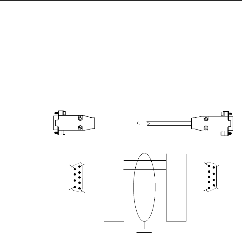
APPENDIXF"Portand CablePin-Outs
6710 Access PointUser’sGuide F-3
DIAGPortCable
DIAGPort
to9-pinMalePCPort
(StandardNull ModemCable)
PartNumber:226-106-001 (6feet)
2
PC
9-pin,D-sub
Female
Pin6Pin1
Pin9Pin5
Pin6
Pin1
Pin5Pin9
6710
9-pin,D-sub
Female
3
3
4
5
6
8
2
1
6
5
4
8
F
6710 PC
SHELL GND

APPENDIXF"Portand CablePin-Outs
F-46710 Access PointUser’sGuide

6710 Access PointUser’sGuide G-1
AppendixG
MIB
""""""""""""""""""""""""""""
ProductContents
The6710 Access PointMIBisondiskpartnumber
215-894-001. OrdertheMIBthroughyourSales
Representative.
Thefollowingproductsareavailableformanagementofthe
openwireless LAN/INCA LAN:
"HPOpenViewforWindows
"OWLViewforHPOpenViewforUNIX
"OWLViewforHPOpenViewforWindows
AboutThisProduct
The6710 Access PointMIBispackagedtoprovidebasic
networkmanagementcapabilityforthe openwireless LAN.
Theaccess point maintainsthefollowingmanagement
objects, whicharespecifictoitsoperation:
"6710MIB.MIB—containsall oftheIntermec
managementobjects supportedonthe6710 Access
Point.
"RFC1213.MIB—isthestandardMIB-II.
"RFC1398.MIB—isthestandardEthernetMIB.

APPENDIXG"MIB
G-26710 Access PointUser’sGuide
TheseMIBsare onthe6710 Access Point’sMIBdisk.You
needtoloadtheMIBsontoyourmanagementplatform to
querytheaccess pointforthesemanagementobjects.
Getting Started
Install theMIBsontoyourmanagementplatforminthis
order:
1.RFC1213.MIB
2.RFC1398.MIB
3.6710MIB.MIB
"NOTE:If you are using HPOpenViewforWindows,usethe OpenView
Control/SNMPManager/Manage Databasemenu itemsto add the
previouslisted MIBstothe HPOpenViewMIBdatabase. If you are
notusing HPOpenViewforWindows,consultyournetwork
managementstation user’sguide forinstructionson adding MIBs.
MIB-II Information
MIB-II isforusewith networkmanagementprotocolsin
TCP/IP-basedinternets.The6710 Access Pointsupports
mostofMIB-II.TableG-1containsthemajorgroups.

APPENDIXG"MIB
6710 Access PointUser’sGuide G-3
TableG-1
MIB-II Information
MIBFamilyOIDPurposeGroups
System1.3.6.1.2.1.1Modeland devicetype
Interfaces1.3.6.1.2.1.2I/O ports
AT1.3.6.1.2.1.3Table ofIPtoMAC/DLCaddress
IP1.3.6.1.2.1.4IPprocess
ICMP1.3.6.1.2.1.5ICMPprocess
TCP1.3.6.1.2.1.6TCPprocess
UDP1.3.6.1.2.1.7UDPprocess
EGP*1.3.6.1.2.1.8EGPprocess
CMOT*1.3.6.1.2.1.9Historical inclusionforOSI
support
Transmission1.3.6.1.2.1.10 Allowsfordata basedonI/O port
typedot3(Ethernet)
SNMP1.3.6.1.2.1.11 Allowsdatatobecollectedabout
SNMPdevices
*The6710 Access Pointdoes notsupportEGPand CMOT.
6710 Access PointMIBInformation
Intermechas structureditsproprietarymanagement
informationsimilartoMIB-II.InadditiontoMIB-II,the
6710 Access Pointsupportsinformationspecifictoits
operation.

APPENDIXG"MIB
G-46710 Access PointUser’sGuide
EXAMPLE:Devicesysteminformation isfound undernSystem, similarto
MIB-II System.The OIDforthe nSystemgroup endsin“1,”justas
the OIDfor MIB-II systemendsin“1.”
TableG-2showsaccess pointMIBinformation.
TableG-2
MIBInformation
MIBFamilyOIDPurposeGroups
nSystem1.3.6.1.4.1.469.1000.2.1Model,device
type,software,
filesystem
hw, file,fsinfo,
segment,dir,
sysErrors,
criticalErrors
nInterfaces1.3.6.1.4.1.469.1000.2.2I/O portsnifx,portState,
portStats,ptxq,
pmsg
nSNMP1.3.6.1.4.1.469.1000.2.11 SNMPcommunity,
trapTarget
nBridge1.3.6.1.4.1.469.1000.2.17 Bridgingrt,brg,addr,
brgState,
bridgeStats
nControl1.3.6.1.4.1.469.1000.2.105 DevicecontrolpowerUp,
softwareDownLoad
Access toManagementInformation
Access toIntermecmanagementinformationisobtained
withtheproperCOMMUNITYname.Intermecprovides
three levelsofaccess.Thistable outlinesthelevelswith
therequiredcommunityname.

APPENDIXG"MIB
6710 Access PointUser’sGuide G-5
"NOTE:Community stringsarecase-sensitive.
Community
StringAccess TypeDescriptionofAccess Type
publicREAD-ONLYMayreadMIBobjects,butnot
write or changevalues.
EXCLUSIONS:Will notbe
abletoreadorwritethe
CommunityTable.
CR52401 READ-WRITEMayreadMIBobjects.May
writetoMIBobjectsthathave
read-writeaccess.
EXCLUSIONS:Will notbe
abletoreadorwritethe
CommunityTable.
secretSUPER-USER MayreadMIBobjects.May
writetoMIBobjectsthathave
read-writeaccess.Canread
andwritetheCommunity
Table.
Thenamesofthecommunitystringsforeachcommunityor
access grouparestoredin(norand.manage.norandNet.
nSNMP.v1Config.communityTable).Thesethree
recordsmaybeviewedandmodifiedifusedwiththe
SUPER-USER community.Thereisamaximum,allowing
forthree levelsofaccess.
Recordsmaybeaddedordeletedviasettingthe
communityStatus object to enable,disable,ordelete.The
firstrowintheCommunityTable isreservedforthe
SUPER-USER communitydefinition.Thisrecordisnot
removable.Thisisafixedrecordto ensureread-write
access totheMIBsonthe6710 Access Point.Notethe
communityName forthefirstrecordcanbechangedto
ensure end-user controlofsecurityforthe6710 Access
Point.

APPENDIXG"MIB
G-66710 Access PointUser’sGuide
MIB-II Notes
SystemGroupThree fieldsintheMIB-II systemgroupare
writable.Thosefieldsare:sysContact,
sysName,andsysLocation.Itis
important that thesevaluesbepreservedin
casethe6710 Access Pointispowered(off
andon)or rebooted.Thefollowingliststhe
numberofcharactersforeachfieldthatwill
bepreservedinthe eventofapower(off and
on)or reboot.
sysContact:31 characters
sysName:31 characters
sysLocation:39 characters
InterfacesGroupTheifTable.ifAdminStatus objectis
read-writeaccessible.However,this
functionalityhasnotbeenenabled.
IP ForwardingIP Forwardingisdisabledforthisrelease of
the6710 Access Point.Therefore,the
MIB-II ipForwardingobjectisnot
changeable.
MIB Directory
Thefollowingpagesdescribethevariousgroupsthe6710
Access Pointsupports.TableG-3listsgroups,their
meaning,and pagenumberswhere eachgroup’stable
summaryand definitionsappear.

APPENDIXG"MIB
6710 Access PointUser’sGuide G-7
TableG-3
MIB Directory
GroupMeaningGroup
SummaryMIB
Definition
ProductOIDs
productsINTERMECRProductsG-8G-24
SystemInformation
hwHardwareInformationG-9G-24
fsinfoFileSystemInformationG-10 G-25
segmentFileSegmentInformationG-10 G-26
dirSoftwareDirectoryListingG-11 G-28
criticalErrorsCriticalErrorsInformationG-11 G-30
InterfaceInformation
nifxNorandExtensionstoInterfaces
TableG-12 G-32
portStatePortStateInformationG-13 G-36
portStatsPortStatisticsG-14 G-41
ptxqPortTransmitQueueG-15 G-46
pmsgPendingMessageServicesG-16 G-49
SNMP Version1Configuration
communityCommunityTableG-17 G-52
trapTargetTrapTargetTableG-17 G-55
BridgingParameters
rtRouteTableG-18 G-56
brgBridgeTableG-19 G-61
addrAddress TableG-20 G-63
brgStateBridgeStateInformationG-20 G-64
bridgeStatsBridgeStatisticsG-22 G-69
ControlGroups
powerUpPowerUpObjectsG-23 G-72
softwareDownLoadSoftwareDownloadG-23 G-72

APPENDIXG"MIB
G-86710 Access PointUser’sGuide
MIBOutline
ProductOIDs
ThisgroupcontainsanObjectIDentification(OID) foreach
INTERMEC device.
TableG-4
productsGROUP
DeviceProducts
norand.manage.products.x
(1.3.6.1.4.1.469.1000.1.x)
OID ObjectNameObjectTypeAccess
1 ap6710 OBJECTIDNotApplicable(N/A)
2gw4030 OBJECTID(N/A)
3wnasOBJECTID(N/A)
4ts6950 OBJECTID(N/A)
5gwap6910 OBJECTID(N/A)
6uap2100 OBJECTID(N/A)
7msd6710 OBJECTID(N/A)

APPENDIXG"MIB
6710 Access PointUser’sGuide G-9
SystemInformation
Thefollowing groupscontainsystemlevelobjectsdescribing
hardwareandfilesystemconfigurationproperties.The
groupsalsocontaininformationaboutcriticalerrors.
"NOTE:The MIBdefinition foreach group startson the page given below.
"hwHardwareInformation(pageG-24)
"fsinfoFileSystemInformation(pageG-25)
"segmentFileSegmentInformation(pageG-26)
"dirSoftwareDirectoryListing(pageG-28)
"criticalErrorsCriticalErrorsInformation
(pageG-30)
TableG-5
hw GROUP
DeviceHardwareInformation
norand.manage.norandNet.nSystem.hw.x
(1.3.6.1.4.1.469.1000.2.1.1.x)
OID ObjectNameObjectTypeAccess
1hwPartNoINTEGER read
2hwDescriptionDisplayStringread
3hwRevisionINTEGER read
4hwSerialNoINTEGER read
5hwIDINTEGER read

APPENDIXG"MIB
G-10 6710 Access PointUser’sGuide
TableG-6
fsinfoGROUP
DeviceFileSystemInformation
norand.manage.norandNet.nSystem.file.fsinfo.x
(1.3.6.1.4.1.469.1000.2.1.3.1.x)
OID ObjectNameObjectTypeAccess
1fsEnabledINTEGER read
2fsMaxSectorsINTEGER read
3fsSectorSizeINTEGER read
4fsNumSegmentsINTEGER read
5fsNumFilesGaugeread
6fsBootSegmentINTEGER read
7fsDataSegmentINTEGER read
TableG-7
segmentGROUP
DeviceFileSegmentInformation
norand.manage.norandNet.nSystem.file.segment.x
(1.3.6.1.4.1.469.1000.2.1.3.2.x)
OID ObjectNameObjectTypeAccess
2.1.1segIDINTEGER read
2.1.2segFirstSectorINTEGER read
2.1.3segLastSectorINTEGER read
2.1.4segStatusINTEGER read
2.1.5segSizeINTEGER read
2.1.6segFree INTEGER read

APPENDIXG"MIB
6710 Access PointUser’sGuide G-11
TableG-8
dirGROUP
DeviceSoftwareDirectoryListing
norand.manage.norandNet.nSystem.file.dir.x
(1.3.6.1.4.1.469.1000.2.1.3.3.x)
OID ObjectNameObjectTypeAccess
2.1.1dirIndexINTEGER read
2.1.2dirNameDisplayStringread
2.1.3dirSegmentINTEGER read
2.1.4dirTypeINTEGER read
2.1.5dirSizeINTEGER read
2.1.6dirDateDisplayStringread
2.1.7dirTimeDisplayStringread
2.1.8dirVersionDisplayStringread
TableG-9
criticalErrorsGROUP
DeviceCriticalErrorsInformation
norand.manage.norandNet.nSystem.sysErrors.criticalErrors.x
(1.3.6.1.4.1.469.1000.2.1.4.1.x)
OID ObjectNameObjectTypeAccess
1ceEnabledINTEGER read
2ceOverflowINTEGER read
3ceResetINTEGER write
4.1.1ceLogErrorCodeINTEGER read
4.1.2ceLogErrorCountCounter read

APPENDIXG"MIB
G-12 6710 Access PointUser’sGuide
Interface Information
Thefollowing groupsrelateinformationaboutNorand
interfaces,portstate,portstatistics,port transmitqueue,
and pendingmessageservices.
"NOTE:The MIBdefinition foreach group startson the page given below.
"nifxNorandExtensionstoInterfacesTable
(pageG-32)
"portStatePortStateInformation(pageG-36)
"portStatsPortStatistics(pageG-41)
"ptxqPortTransmitQueue(pageG-46)
"pmsgPendingMessageServices(pageG-49)
TableG-10
nifxGROUP
NorandExtensionstoMIB-II InterfacesTable
norand.manage.norandNet.nInterfaces.nifx.x
(1.3.6.1.4.1.469.1000.2.2.2.x)
OID ObjectNameObjectTypeAccess
4.1.1nifxIndexINTEGER read
4.1.2nifxTypeINTEGER read
4.1.3nifxInDisabledDiscardsCounter read
4.1.4nifxInOverrunsCounter read
4.1.5nifxInHWOverrunsCounter read
4.1.6nifxInUcastDPktsCounter read
4.1.7nifxInNUcastDPktsCounter read
4.1.8nifxInLenErrorsCounter read
4.1.9nifxExcessiveDeferralsCounter read
4.1.10 nifxInNetIDDiscardsCounter read
4.1.11 nifxInFragDiscardsCounter read
4.1.12 nifxInUFilterDiscardsCounter read
4.1.13 nifxInNUFilterDiscardsCounter read
4.1.14 nifxInQFullDiscardsCounter read

APPENDIXG"MIB
6710 Access PointUser’sGuide G-13
TableG-11
portStateGROUP
DevicePortStateInformation
norand.manage.norandNet.nInterfaces.portState.x
(1.3.6.1.4.1.469.1000.2.2.3.x)
OID ObjectNameObjectTypeAccess
4.1.1psPortINTEGER read
4.1.2psIfIndexINTEGER read
4.1.3psAddress PhysAddress read
4.1.4psTypeINTEGER read
4.1.5psStateINTEGER read
4.1.6psCostINTEGER read
4.1.7psHelloPeriodINTEGER read
4.1.8psHelloCountCounter read
4.1.9psMacdWindowINTEGER read
4.1.10 psMacdQSizeGaugeread
4.1.11 psMacdTimeoutsCounter read
4.1.12 psIsPrimaryINTEGER read
4.1.13 psIsSecondaryINTEGER read
4.1.14 psIsSecondaryCandidateINTEGER read
4.1.15 psSecondaryUniFloodingINTEGER read
4.1.16 psSecondaryMultiFloodingINTEGER read
4.1.17 psIsRadioINTEGER read
4.1.18 psPendEnabledINTEGER read

APPENDIXG"MIB
G-14 6710 Access PointUser’sGuide
TableG-12
portStatsGROUP
DevicePortStatistics
norand.manage.norandNet.nInterfaces.portStats.x
(1.3.6.1.4.1.469.1000.2.2.4.x)
OID ObjectNameObjectTypeAccess
4.1.1pstcPortINTEGER read
4.1.2pstcInOWLPktsCounter read
4.1.3pstcInUcastOWLDataPktsCounter read
4.1.4pstcInNUcastOWLDataPktsCounter read
4.1.5pstcInOWLErrorsCounter read
4.1.6pstcOutOWLPktsCounter read
4.1.7pstcOutUcastOWLDataPktsCounter read
4.1.8pstcOutNUcastOWLDataPktsCounter read
4.1.9pstcOutOWLErrorsCounter read
4.1.10 pstcParentLinkErrorsCounter read
4.1.11 pstcAlertLinkErrorsCounter read
4.1.12 pstcInUcastRelayPktsCounter read
4.1.13 pstcInNUcastRelayPktsCounter read
4.1.14 pstcOutUcastRelayPktsCounter read
4.1.15 pstcOutNUcastRelayPktsCounter read
4.1.16 pstcInUcastInboundCounter read
4.1.17 pstcInUcastOutboundCounter read
4.1.18 pstcInUcastSecCounter read
4.1.19 pstcInUcastFloodCounter read
4.1.20 pstcUcastDiscardsCounter read
4.1.21 pstcInNUcastDiscardsCounter read
4.1.22 pstcInUcastToIFC Counter read
4.1.23 pstcInNUcastToIFC Counter read
4.1.24 pstcOutDelayDiscardsCounter read

APPENDIXG"MIB
6710 Access PointUser’sGuide G-15
TableG-13
ptxqGROUP
DevicePortTransmitQueue
norand.manage.norandNet.nInterfaces.ptxq.x
(1.3.6.1.4.1.469.1000.2.2.5.x)
OID ObjectNameObjectTypeAccess
1.1.1ptxqPortINTEGER read
1.1.2ptxqRegQSizeGaugeread
1.1.3ptxqRegQMaxINTEGER read
1.1.4ptxqExpQSizeGaugeread
1.1.5ptxqExpQMaxINTEGER read
1.1.6ptxqQHpCountCounter read
1.1.7ptxqQExpCountCounter read
1.1.8ptxqQRegCountCounter read
1.1.9ptxqQHpDiscardsCounter read
1.1.10 ptxqQExpDiscardsCounter read
1.1.11 ptxqQRegDiscardsCounter read
1.1.12 ptxqMultiQSizeGaugeread
1.1.13 ptxqMultiQMaxINTEGER read
1.1.14 ptxqMultiQDiscardsCounter read

APPENDIXG"MIB
G-16 6710 Access PointUser’sGuide
TableG-14
pmsgGROUP
DevicePendingMessageService
norand.manage.norandNet.nInterfaces.pmsg.x
(1.3.6.1.4.1.469.1000.2.2.6.x)
OID ObjectNameObjectTypeAccess
1.1.1pmsgPortINTEGER read
1.1.2pmsgPendRecCurrentGaugeread
1.1.3pmsgPendRecMaxINTEGER read
1.1.4pmsgPendMsgCurrentGaugeread
1.1.5pmsgPendMsgMaxINTEGER read
1.1.6pmsgPendMsgTotalCounter read
1.1.7pmsgPendMsgDiscardsCounter read
1.1.8pmsgPendRecOverflowErrorsCounter read
1.1.9pmsgPendMsgOverflowErrorsCounter read
1.1.10 pmsgPendAgedRecCountCounter read
1.1.11 pmsgPendAgedMsgCountCounter read

APPENDIXG"MIB
6710 Access PointUser’sGuide G-17
SNMP Version 1Configuration
Group
Thisgroupcontainsobjectsthatconfiguretheversion1
SimpleNetworkManagementProtocol(SNMP)agent.
"NOTE:The MIBdefinition foreach group startson the page given below.
"communityCommunityTable(pageG-52)
"trapTargetTrapTargetTable(pageG-55)
TableG-15
communityTABLE
DeviceSNMPv1Configurations
norand.manage.norandNet.nSNMP.v1Config.x
(1.3.6.1.4.1.469.1000.2.11.1.x)
OID ObjectNameObjectTypeAccess
2.1.1communityIndexINTEGER read
2.1.2communityStatusINTEGER write
2.1.3communityNameDisplayStringwrite
2.1.4communityPrivilegesINTEGER write
TableG-16
trapTargetTABLE
DeviceSNMPv1Configurations
norand.manage.norandNet.nSNMP.v1Config.x
(1.3.6.1.4.1.469.1000.2.11.1.x)
OID ObjectNameObjectTypeAccess
3.1.1trapTargetIndexINTEGER read
3.1.2trapTargetStatusINTEGER write
3.1.3trapTargetNameDisplayStringwrite
3.1.4trapTargetIpAddress IpAddress write

APPENDIXG"MIB
G-18 6710 Access PointUser’sGuide
Bridging Parameters
Thefollowing groupscontainobjectsrelatingtothewireless
transparentbridgingoperation.
"NOTE:The MIBdefinition foreach group startson the page given below.
"rtRouteTable(pageG-56)
"brgBridgeTable(pageG-61)
"addrAddress Table(pageG-63)
"brgStateBridgeStateInformation(pageG-64)
"bridgeStatsBridgeStatistics(pageG-69)
TableG-17
rtGROUP
DeviceRouteTable
norand.manage.norandNet.nBridge.rt.x
(1.3.6.1.4.1.469.1000.2.17.2.x)
OID ObjectNameObjectTypeAccess
2.1.1rtDestinationPhysAddress read
2.1.2rtPortINTEGER read
2.1.3rtAgeINTEGER read
2.1.4rtNodeIdINTEGER read
2.1.5rtAttachIdINTEGER read
2.1.6rtAttachTimeTimeTicksread
2.1.7rtApEaddrPhysAddress read
2.1.8rtHopAddrLenINTEGER read
2.1.9rtHopAddr16 INTEGER read

APPENDIXG"MIB
6710 Access PointUser’sGuide G-19
TableG-17 (Continued)
rtGROUP
DeviceRouteTable
norand.manage.norandNet.nBridge.rt.x
(1.3.6.1.4.1.469.1000.2.17.2.x)
OIDAccessObjectTypeObjectName
2.1.10 rtHopEaddrPhysAddress read
2.1.11 rtIsBoundINTEGER read
2.1.12 rtIsRemoteINTEGER read
2.1.13 rtIsChildINTEGER read
2.1.14 rtIsApINTEGER read
2.1.15 rtIsDistributedINTEGER read
2.1.16 rtIsRemoteLanINTEGER read
2.1.17 rtNSINTEGER read
2.1.18 rtNRINTEGER read
TableG-18
brgGROUP
DeviceBridgeTable
norand.manage.norandNet.nBridge.brg.x
(1.3.6.1.4.1.469.1000.2.17.3.x)
OID ObjectNameObjectTypeAccess
2.1.1 brgDestinationPhysAddress read
2.1.2 brgPortINTEGER read
2.1.3 brgAgeINTEGER read
2.1.4 brgTypeINTEGER read
2.1.5 brgIsPermanentINTEGER read
2.1.6 brgTimestampTimeTicksread

APPENDIXG"MIB
G-20 6710 Access PointUser’sGuide
TableG-19
addrGROUP
Address Table
norand.manage.norandNet.nBridge.addr.x
(1.3.6.1.4.1.469.1000.2.17.4.x)
OID ObjectNameObjectTypeAccess
2.1.1 addrDestinationPhysAddress read
2.1.2 addrAgeINTEGER read
2.1.3 addrNodeIdINTEGER read
2.1.4 addrAliasDisplayStringread
2.1.5 addrDeviceIdINTEGER read
2.1.6 addrIpAddress IPAddress read
TableG-20
brgStateGROUP
BridgeStateInformation
norand.manage.norandNet.nBridge.brgState.x
(1.3.6.1.4.1.469.1000.2.17.6.x)
OID ObjectNameObjectTypeAccess
3 bsAddress PhysAddress read
4 bsLanIdINTEGER read
5 bsCostToRootINTEGER read
6 bsIsRootINTEGER read
7 bsIsAttachedINTEGER read
8 bsAttachIdINTEGER read
9 bsMyRootPriorityINTEGER read
10 bsRootPortINTEGER read

APPENDIXG"MIB
6710 Access PointUser’sGuide G-21
TableG-20 (Continued)
brgStateGROUP
BridgeStateInformation
norand.manage.norandNet.nBridge.brgState.x
(1.3.6.1.4.1.469.1000.2.17.6.x)
OIDAccessObjectTypeObjectName
11 bsDesignatedRootAddress PhysAddress read
12 bsDesignatedRootPriorityINTEGER read
13 bsDesignatedRootSequenceINTEGER read
14 bsParentAddress PhysAddress read
15 bsPortCountINTEGER read
16 bsNodeIdINTEGER read
17 bsRootChangedCountCounter read
18 bsRootCountCounter read
19 bsAttachCountCounter read
20 bsDetachReasonINTEGER read
21 bsNetworkTimeTimeTicksread
22 bsUniFloodLevelINTEGER read
23 bsMultiFloodLevelINTEGER read
24 bsIsPrimaryBridgeINTEGER read
25 bsIsSecondaryBridgeINTEGER read
26 bsUniFilterExprINTEGER read
27 bsMultiFilterExprINTEGER read

APPENDIXG"MIB
G-22 6710 Access PointUser’sGuide
TableG-21
bridgeStatsGROUP
BridgeStatistics
norand.manage.norandNet.nBridge.bridgeStats.x
(1.3.6.1.4.1.469.1000.2.17.7.x)
OID ObjectNameObjectTypeAccess
3 bstcRouteCountGaugeread
4 bstcChildCountGaugeread
5 bstcChildApCountGaugeread
6 bstcRemoteCountGaugeread
7 bstcPrimaryCountGaugeread
8 bstcInboundCountGaugeread
9 bstcSecondaryCountGaugeread
10 bstcRemoteLanCountGaugeread
11 bstcRouteGetErrorsCounter read
12 bstcEntryGetErrorsCounter read
13 bstcRmtLanGetErrorsCounter read
14 bstcRouteSeqErrorsCounter read
15 bstcDeleteSeqErrorsCounter read
16 bstcEntrySeqErrorsCounter read
17 bstcInvalidUpdateErrorsCounter read
ControlGroups
Objectsinthefollowing groupsexertcontroloverthe6710
Access Point.Presentfunctionsincluderebootingand
schedulingsoftwaredownloads.
"NOTE:The MIBdefinition foreach group startson the page given below.
"powerUpPowerUpObjects(pageG-72)
"softwareDownLoadSoftwareDownload(pageG-72)

APPENDIXG"MIB
6710 Access PointUser’sGuide G-23
TableG-22
powerUpGROUP
DevicePowerUpObjects
norand.manage.norandNet.nControl.powerUp.x
(1.3.6.1.4.1.469.1000.2.105.1.x)
OID ObjectNameObjectTypeAccess
1pwrPowerUpCountCounter read
2pwrNextPowerUpTimeTimeTickswrite
TableG-23
softwareDownLoadGROUP
DeviceSoftwareDownload
norand.manage.norandNet.nControl.softwareDownLoad.x
(1.3.6.1.4.1.469.1000.2.105.2.x)
OID ObjectNameObjectTypeAccess
1sdStartTimeTimeTickswrite
2sdServerIpAddress IpAddress write
3sdScriptFilenameDisplayStringwrite
4sdStatusINTEGER read
5sdErrorStringDisplayStringread
6sdCheckPointINTEGER write
7sdSetActivePointersINTEGER write
8sdTerminateINTEGER write
MIB Definitions
FollowingaretheMIBdefinitionsforthe6710 Access
Point.

APPENDIXG"MIB
G-24 6710 Access PointUser’sGuide
-- ******************************************************************
-- *
-- * 6710MIB.MIB Version 1.32
-- *
-- ******************************************************************
OWL DEFINITIONS ::= BEGIN
IMPORTS
enterprises, IpAddress, Counter, Gauge, TimeTicks
FROM RFC1155-SMI
PhysAddress, DisplayString
FROM RFC1213-MIB
OBJECT-TYPE
FROM RFC-1212;
-- This MIB module uses the extended OBJECT-TYPE macro as
-- defined in RFC-1212;
norand OBJECT IDENTIFIER ::= { enterprises 469 }
manage OBJECT IDENTIFIER ::= { norand 1000 }
products OBJECT IDENTIFIER ::= { manage 1 }
ap6710 OBJECT IDENTIFIER ::= { products 1 }
gw4030 OBJECT IDENTIFIER ::= { products 2 }
wnas OBJECT IDENTIFIER ::= { products 3 }
ts6950 OBJECT IDENTIFIER ::= { products 4 }
gwap6910 OBJECT IDENTIFIER ::= { products 5 }
uap2100 OBJECT IDENTIFIER ::= { products 6 }
msd6710 OBJECT IDENTIFIER ::= { products 7 }
norandNET OBJECT IDENTIFIER ::= { manage 2 }
nSystem OBJECT IDENTIFIER ::= { norandNET 1 }
hw OBJECT IDENTIFIER ::= { nSystem 1 }
-- The Hardware Parameters Group
hwPartNo OBJECT-TYPE
SYNTAX INTEGER (0..2147483647)
ACCESS read-only
STATUS mandatory
DESCRIPTION
”The Norand part number of the hardware device.”
::= { hw 1 }
hwDescription OBJECT-TYPE
SYNTAX DisplayString (SIZE (0..40))
ACCESS read-only
STATUS mandatory
DESCRIPTION
”The description of the hardware device.”
::= { hw 2 }

APPENDIXG"MIB
6710 Access PointUser’sGuide G-25
hwRevision OBJECT-TYPE
SYNTAX INTEGER (0..2147483647)
ACCESS read-only
STATUS mandatory
DESCRIPTION
”The revision level of the hardware device.”
::= { hw 3 }
hwSerialNo OBJECT-TYPE
SYNTAX INTEGER (0..2147483647)
ACCESS read-only
STATUS mandatory
DESCRIPTION
”The serial number of the hardware device.”
::= { hw 4 }
hwID OBJECT-TYPE
SYNTAX INTEGER (0..2147483647)
ACCESS read-only
STATUS mandatory
DESCRIPTION
”The device identifier of the hardware device.
Values = 3250, 4000, 4020, 4030, 4033, 3240, 1000,
1100, 1700, 5940, 4650, 100 (ACE process), 200
(DOSNMS), 300 (Norand Proxy Agent), 6710 (Access
Point).”
::= { hw 5 }
file OBJECT IDENTIFIER ::= { nSystem 3 }
fsinfo OBJECT IDENTIFIER ::= { file 1 }
-- The FileSystem Information Table
fsEnabled OBJECT-TYPE
SYNTAX INTEGER { true(1), false(2) }
ACCESS read-only
STATUS mandatory
DESCRIPTION
”TRUE, if the file system is enabled”
::= { fsinfo 1 }
fsMaxSectors OBJECT-TYPE
SYNTAX INTEGER
ACCESS read-only
STATUS mandatory
DESCRIPTION
”The number of physical sectors. A file
segment consists of one or more adjacent
physical sectors.”
::= { fsinfo 2 }

APPENDIXG"MIB
G-26 6710 Access PointUser’sGuide
fsSectorSize OBJECT-TYPE
SYNTAX INTEGER
ACCESS read-only
STATUS mandatory
DESCRIPTION
”The size of a physical sector in bytes.”
::= { fsinfo 3 }
fsNumSegments OBJECT-TYPE
SYNTAX INTEGER
ACCESS read-only
STATUS mandatory
DESCRIPTION
”The number of logical file segments
(0-MAX_SECTORS)”
::= { fsinfo 4 }
fsNumFiles OBJECT-TYPE
SYNTAX Gauge
ACCESS read-only
STATUS mandatory
DESCRIPTION
”The number of files (0-25)”
::= { fsinfo 5 }
fsBootSegment OBJECT-TYPE
SYNTAX INTEGER
ACCESS read-only
STATUS mandatory
DESCRIPTION
”The index of the current boot segment. If the
index is non-zero and the first file in the
associated segment is executable, then control
is passed to that file during the power-up
sequence.”
::= { fsinfo 6 }
fsDataSegment OBJECT-TYPE
SYNTAX INTEGER
ACCESS read-only
STATUS mandatory
DESCRIPTION
”The index of the active data segment. Files
stored in this segment will be accessible to an
executing application.”
::= { fsinfo 7 }
segment OBJECT IDENTIFIER ::= { file 2 }
-- The File Segment Table
-- Table Definition

APPENDIXG"MIB
6710 Access PointUser’sGuide G-27
segTable OBJECT-TYPE
SYNTAX SEQUENCE OF SEGEntry
ACCESS not-accessible
STATUS mandatory
DESCRIPTION
””
::= { segment 2 }
-- Row Definition
segEntry OBJECT-TYPE
SYNTAX SEGEntry
ACCESS not-accessible
STATUS mandatory
INDEX { segID }
::= { segTable 1 }
-- Columnar Object Definitions
SEGEntry ::=
SEQUENCE {
segID INTEGER,
segFirstSector INTEGER,
segLastSector INTEGER,
segStatus INTEGER,
segSize INTEGER,
segFree INTEGER
}
segID OBJECT-TYPE
SYNTAX INTEGER
ACCESS read-only
STATUS mandatory
DESCRIPTION
”The segment ID (1 - (NUM_SEGMENTS+1)). A
non-zero number which uniquely identifies a
segment.”
::= { segEntry 1 }
segFirstSector OBJECT-TYPE
SYNTAX INTEGER
ACCESS read-only
STATUS mandatory
DESCRIPTION
”The first physical sector in the segment
(1 - (MAX_SECTORS + 1))”
::= { segEntry 2 }

APPENDIXG"MIB
G-28 6710 Access PointUser’sGuide
segLastSector OBJECT-TYPE
SYNTAX INTEGER
ACCESS read-only
STATUS mandatory
DESCRIPTION
”The last physical sector in the segment
(FIRST_SECTOR - (MAX_SECTORS + 1))”
::= { segEntry 3 }
segStatus OBJECT-TYPE
SYNTAX INTEGER { valid(1),
invalid(2) }
ACCESS read-only
STATUS mandatory
DESCRIPTION
”The segment status:
valid = 1,
invalid = 2 ”
::= { segEntry 4 }
segSize OBJECT-TYPE
SYNTAX INTEGER
ACCESS read-only
STATUS mandatory
DESCRIPTION
”The segment size in bytes”
::= { segEntry 5 }
segFree OBJECT-TYPE
SYNTAX INTEGER
ACCESS read-only
STATUS mandatory
DESCRIPTION
”The number of available bytes in the segment
which are not currently allocated to a file.”
::= { segEntry 6 }
dir OBJECT IDENTIFIER ::= { file 3 }
-- The File Directory Table
-- Table Definition
dirTable OBJECT-TYPE
SYNTAX SEQUENCE OF DIREntry
ACCESS not-accessible
STATUS mandatory
DESCRIPTION
”The FileSystem Directory”
::= { dir 2 }
-- Row Definition

APPENDIXG"MIB
6710 Access PointUser’sGuide G-29
dirEntry OBJECT-TYPE
SYNTAX DIREntry
ACCESS not-accessible
STATUS mandatory
INDEX { dirIndex }
::= { dirTable 1 }
-- Columnar Object Definitions
DIREntry ::=
SEQUENCE {
dirIndex INTEGER,
dirName DisplayString,
dirSegment INTEGER,
dirType INTEGER,
dirSize INTEGER,
dirDate DisplayString,
dirTime DisplayString,
dirVersion DisplayString
}
dirIndex OBJECT-TYPE
SYNTAX INTEGER
ACCESS read-only
STATUS mandatory
DESCRIPTION
”Directory Index”
::= { dirEntry 1 }
dirName OBJECT-TYPE
SYNTAX DisplayString (SIZE (0..14))
ACCESS read-only
STATUS mandatory
DESCRIPTION
”File name”
::= { dirEntry 2 }
dirSegment OBJECT-TYPE
SYNTAX INTEGER
ACCESS read-only
STATUS mandatory
DESCRIPTION
”File segment (1 - (NUM_SEGMENTS + 1)).
The segment ID which identifies the segment
containing the file.”
::= { dirEntry 3 }

APPENDIXG"MIB
G-30 6710 Access PointUser’sGuide
dirType OBJECT-TYPE
SYNTAX INTEGER { executable(1),
data(2),
invalid(3) }
ACCESS read-only
STATUS mandatory
DESCRIPTION
”File type:
executable = 1,
data = 2,
invalid = 3 ”
::= { dirEntry 4 }
dirSize OBJECT-TYPE
SYNTAX INTEGER
ACCESS read-only
STATUS mandatory
DESCRIPTION
”The file size in bytes”
::= { dirEntry 5 }
dirDate OBJECT-TYPE
SYNTAX DisplayString (SIZE (0..12))
ACCESS read-only
STATUS mandatory
DESCRIPTION
”The file date in MM-DD-YYYY display format.”
::= { dirEntry 6 }
dirTime OBJECT-TYPE
SYNTAX DisplayString (SIZE (0..10))
ACCESS read-only
STATUS mandatory
DESCRIPTION
”The file time in HH:MM:SS display format.”
::= { dirEntry 7 }
dirVersion OBJECT-TYPE
SYNTAX DisplayString (SIZE (0..8))
ACCESS read-only
STATUS mandatory
DESCRIPTION
”The file version in v99.99 display format.”
::= { dirEntry 8 }
sysErrors OBJECT IDENTIFIER ::= { nSystem 4 }
criticalErrors OBJECT IDENTIFIER ::= { sysErrors 1 }

APPENDIXG"MIB
6710 Access PointUser’sGuide G-31
ceEnabled OBJECT-TYPE
SYNTAX INTEGER { true(1), false(2) }
ACCESS read-only
STATUS mandatory
DESCRIPTION
”A value of true(1) signifies that the critical
error log was successfully initialized as part
of the power-up sequence. Any errors in that
initialization process result in a value of
false(2).”
::= { criticalErrors 1 }
ceOverflow OBJECT-TYPE
SYNTAX INTEGER
ACCESS read-only
STATUS mandatory
DESCRIPTION
”Overflow error code. If the overflow code is
non-zero, it indicates that the log has
overflowed and the overflow code contains the
last displaced value.”
::= { criticalErrors 2 }
ceReset OBJECT-TYPE
SYNTAX INTEGER { true(1), false(2) }
ACCESS read-write
STATUS mandatory
DESCRIPTION
”A user can reset the critical error log by
setting ceReset to true(1). Valid values are
true(1) or false(2).”
::= { criticalErrors 3 }
ceLogTable OBJECT-TYPE
SYNTAX SEQUENCE OF CELogEntry
ACCESS not-accessible
STATUS mandatory
DESCRIPTION
”Critical Error Log Table”
::= { criticalErrors 4 }
ceLogEntry OBJECT-TYPE
SYNTAX CELogEntry
ACCESS not-accessible
STATUS mandatory
INDEX { ceLogErrorCode }
::= { ceLogTable 1 }

APPENDIXG"MIB
G-32 6710 Access PointUser’sGuide
CELogEntry ::=
SEQUENCE {
ceLogErrorCode INTEGER,
ceLogErrorCount Counter
}
ceLogErrorCode OBJECT-TYPE
SYNTAX INTEGER
ACCESS read-only
STATUS mandatory
DESCRIPTION
”Critical error code. A 16-bit value which
uniquely indentifies a system software error.
The error codes are intended for internal
Norand use.”
::= { ceLogEntry 1 }
ceLogErrorCount OBJECT-TYPE
SYNTAX Counter
ACCESS read-only
STATUS mandatory
DESCRIPTION
”Error count for the associated ceLogErrorCode”
::= { ceLogEntry 2 }
nInterfaces OBJECT IDENTIFIER ::= { norandNET 2 }
nifx OBJECT IDENTIFIER ::= { nInterfaces 2 }
-- The Norand Extended Interfaces Table
nifxTable OBJECT-TYPE
SYNTAX SEQUENCE OF NIFXEntry
ACCESS not-accessible
STATUS mandatory
DESCRIPTION
”Norand Extended Interface Table”
::= { nifx 4 }
nifxEntry OBJECT-TYPE
SYNTAX NIFXEntry
ACCESS not-accessible
STATUS mandatory
INDEX { nifxIndex }
::= { nifxTable 1 }

APPENDIXG"MIB
6710 Access PointUser’sGuide G-33
NIFXEntry ::=
SEQUENCE {
nifxIndex INTEGER,
nifxType INTEGER,
nifxInDisabledDiscards Counter,
nifxInOverruns Counter,
nifxInHWOverruns Counter,
nifxInUcastDPkts Counter,
nifxInNUcastDPkts Counter,
nifxInLenErrors Counter,
nifxExcessiveDeferrals Counter,
nifxInNetIDDiscards Counter,
nifxInFragDiscards Counter,
nifxInUFilterDiscards Counter,
nifxInNUFilterDiscards Counter,
nifxInQFullDiscards Counter
}
nifxIndex OBJECT-TYPE
SYNTAX INTEGER
ACCESS read-only
STATUS mandatory
DESCRIPTION
”Interface index”
::={ nifxEntry 1 }
nifxType OBJECT-TYPE
SYNTAX INTEGER { ether(4),
bb485(33),
owlIP(66),
proxim24(132),
nor24(195),
falcon902(197),
uhf(198)
}
ACCESS read-only
STATUS mandatory
DESCRIPTION
”Norand Interface Type”
::={ nifxEntry 2 }

APPENDIXG"MIB
G-34 6710 Access PointUser’sGuide
nifxInDisabledDiscards OBJECT-TYPE
SYNTAX Counter
ACCESS read-only
STATUS mandatory
DESCRIPTION
”The number of received unicast frames which do
not require forwarding. Unicast ethernet frames are
discarded if ether-to-radio flooding is disabled
and the destination is unknown; otherwise, unicast
frames are discarded if the bridge has learned that
the destination port is the same as the source port”
::={ nifxEntry 3 }
nifxInOverruns OBJECT-TYPE
SYNTAX Counter
ACCESS read-only
STATUS mandatory
DESCRIPTION
”The number of received frames discarded because the
frame could not be queued for the MAC-D task”
::={ nifxEntry 4 }
nifxInHWOverruns OBJECT-TYPE
SYNTAX Counter
ACCESS read-only
STATUS mandatory
DESCRIPTION
”The number of received frames discarded due to
hardware overruns.”
::={ nifxEntry 5 }
nifxInUcastDPkts OBJECT-TYPE
SYNTAX Counter
ACCESS read-only
STATUS mandatory
DESCRIPTION
”The number of received unicast frames successfully
delivered to the MAC-D task”
::={ nifxEntry 6 }
nifxInNUcastDPkts OBJECT-TYPE
SYNTAX Counter
ACCESS read-only
STATUS mandatory
DESCRIPTION
”The number of received multicast frames
successfully delivered to the MAC-D task”
::={ nifxEntry 7 }

APPENDIXG"MIB
6710 Access PointUser’sGuide G-35
nifxInLenErrors OBJECT-TYPE
SYNTAX Counter
ACCESS read-only
STATUS mandatory
DESCRIPTION
”The number received frames with length errors”
::={ nifxEntry 8 }
nifxExcessiveDeferrals OBJECT-TYPE
SYNTAX Counter
ACCESS read-only
STATUS mandatory
DESCRIPTION
”The number of aborted transmissions due to
excessive deferrals”
::={ nifxEntry 9 }
nifxInNetIDDiscards OBJECT-TYPE
SYNTAX Counter
ACCESS read-only
STATUS mandatory
DESCRIPTION
”The number of received frames discarded because the
LAN ID did not match”
::={ nifxEntry 10 }
nifxInFragDiscards OBJECT-TYPE
SYNTAX Counter
ACCESS read-only
STATUS mandatory
DESCRIPTION
”The number of received frame fragments discarded
because a fragmented frame could not be
re-assembled”
::={ nifxEntry 11 }
nifxInUFilterDiscards OBJECT-TYPE
SYNTAX Counter
ACCESS read-only
STATUS mandatory
DESCRIPTION
”The number of enabled received unicast frames
discarded due to a unicast filter expression”
::={ nifxEntry 12 }

APPENDIXG"MIB
G-36 6710 Access PointUser’sGuide
nifxInNUFilterDiscards OBJECT-TYPE
SYNTAX Counter
ACCESS read-only
STATUS mandatory
DESCRIPTION
”The number of enabled received multicast frames
discarded due to a multicast filter expression”
::={ nifxEntry 13 }
nifxInQFullDiscards OBJECT-TYPE
SYNTAX Counter
ACCESS read-only
STATUS mandatory
DESCRIPTION
”The number of received frames discarded because the
frame could not be queued for the MAC-R task”
::={ nifxEntry 14 }
portState OBJECT IDENTIFIER ::= { nInterfaces 3 }
-- The Port State Table
psTable OBJECT-TYPE
SYNTAX SEQUENCE OF PSEntry
ACCESS not-accessible
STATUS mandatory
DESCRIPTION
”MAC-R port state variables”
::= { portState 4 }
psEntry OBJECT-TYPE
SYNTAX PSEntry
ACCESS not-accessible
STATUS mandatory
INDEX { psPort }
::= { psTable 1 }

APPENDIXG"MIB
6710 Access PointUser’sGuide G-37
PSEntry ::=
SEQUENCE {
psPort INTEGER,
psIfIndex INTEGER,
psAddress PhysAddress,
psType INTEGER,
psState INTEGER,
psCost INTEGER,
psHelloPeriod INTEGER,
psHelloCount Counter,
psMacdWindow INTEGER,
psMacdQSize Gauge,
psMacdTimeouts Counter,
psIsPrimary INTEGER,
psIsSecondary INTEGER,
psIsSecondaryCandidate INTEGER,
psSecondaryUniFlooding INTEGER,
psSecondaryMultiFlooding INTEGER,
psIsRadio INTEGER,
psPendEnabled INTEGER
}
psPort OBJECT-TYPE
SYNTAX INTEGER (1..4)
ACCESS read-only
STATUS mandatory
DESCRIPTION
”MAC-R port ID (1-4). A number which uniquely
identifies the port.”
::= { psEntry 1 }
psIfIndex OBJECT-TYPE
SYNTAX INTEGER
ACCESS read-only
STATUS mandatory
DESCRIPTION
”MAC-D interface index. The index matches the
interface index of the associated row in the mib-II
interface table.”
::= { psEntry 2 }
psAddress OBJECT-TYPE
SYNTAX PhysAddress
ACCESS read-only
STATUS mandatory
DESCRIPTION
”802 address of the port”
::= { psEntry 3 }

APPENDIXG"MIB
G-38 6710 Access PointUser’sGuide
psType OBJECT-TYPE
SYNTAX INTEGER { ether(4),
bb485(33),
owlIP(66),
proxim24(132),
nor24(195),
falcon902(197),
uhf(198)
}
ACCESS read-only
STATUS mandatory
DESCRIPTION
”Norand port type:
ether = 4,
Proxim = 196,
Falcon = 197,
UHF = 198”
::= { psEntry 4 }
psState OBJECT-TYPE
SYNTAX INTEGER { disabled(0),
idle(1),
open(2),
receive(3),
transmit(4) }
ACCESS read-only
STATUS mandatory
DESCRIPTION
”Port state:
disabled = 0,
idle = 1,
open = 2,
receive = 3,
transmit = 4 ”
::= { psEntry 5 }
psCost OBJECT-TYPE
SYNTAX INTEGER
ACCESS read-only
STATUS mandatory
DESCRIPTION
”Incremental path cost of the port.
Default values:
ether = 20,
Falcon = 100,
UHF = 255 ”
::= { psEntry 6 }

APPENDIXG"MIB
6710 Access PointUser’sGuide G-39
psHelloPeriod OBJECT-TYPE
SYNTAX INTEGER
ACCESS read-only
STATUS mandatory
DESCRIPTION
”Inter-HELLO time (.01 secs.)”
::= { psEntry 7 }
psHelloCount OBJECT-TYPE
SYNTAX Counter
ACCESS read-only
STATUS mandatory
DESCRIPTION
”HELLO transmit count”
::= { psEntry 8 }
psMacdWindow OBJECT-TYPE
SYNTAX INTEGER
ACCESS read-only
STATUS mandatory
DESCRIPTION
”Max. number of active MAC-D transmit requests”
::= { psEntry 9 }
psMacdQSize OBJECT-TYPE
SYNTAX Gauge
ACCESS read-only
STATUS mandatory
DESCRIPTION
”Current number of active MAC-D transmit requests”
::= { psEntry 10 }
psMacdTimeouts OBJECT-TYPE
SYNTAX Counter
ACCESS read-only
STATUS mandatory
DESCRIPTION
”MAC-D transmit timeout errors”
::= { psEntry 11 }
psIsPrimary OBJECT-TYPE
SYNTAX INTEGER { true(1), false(2) }
ACCESS read-only
STATUS mandatory
DESCRIPTION
”TRUE, for primary bridge ports”
::= { psEntry 12 }

APPENDIXG"MIB
G-40 6710 Access PointUser’sGuide
psIsSecondary OBJECT-TYPE
SYNTAX INTEGER { true(1), false(2) }
ACCESS read-only
STATUS mandatory
DESCRIPTION
”TRUE, for secondary bridge ports”
::= { psEntry 13 }
psIsSecondaryCandidate OBJECT-TYPE
SYNTAX INTEGER { true(1), false(2) }
ACCESS read-only
STATUS mandatory
DESCRIPTION
”TRUE, if secondary bridge port candidates”
::= { psEntry 14 }
psSecondaryUniFlooding OBJECT-TYPE
SYNTAX INTEGER { true(1), false(2) }
ACCESS read-only
STATUS mandatory
DESCRIPTION
”TRUE, for secondary bridge ports which require
unicast flooding”
::= { psEntry 15 }
psSecondaryMultiFlooding OBJECT-TYPE
SYNTAX INTEGER { true(1), false(2) }
ACCESS read-only
STATUS mandatory
DESCRIPTION
”TRUE, for secondary bridge ports which require
multicast flooding”
::= { psEntry 16 }
psIsRadio OBJECT-TYPE
SYNTAX INTEGER { true(1), false(2) }
ACCESS read-only
STATUS mandatory
DESCRIPTION
”TRUE, for radio ports”
::= { psEntry 17 }
psPendEnabled OBJECT-TYPE
SYNTAX INTEGER { true(1), false(2) }
ACCESS read-only
STATUS mandatory
DESCRIPTION
”TRUE, if the port supports pending messages”
::= { psEntry 18 }

APPENDIXG"MIB
6710 Access PointUser’sGuide G-41
portStats OBJECT IDENTIFIER ::= { nInterfaces 4 }
pstcTable OBJECT-TYPE
SYNTAX SEQUENCE OF PSTCEntry
ACCESS not-accessible
STATUS mandatory
DESCRIPTION
”MAC-R port state variables”
::= { portStats 4 }
pstcEntry OBJECT-TYPE
SYNTAX PSTCEntry
ACCESS not-accessible
STATUS mandatory
INDEX { pstcPort }
::= { pstcTable 1 }
PSTCEntry ::=
SEQUENCE {
pstcPort INTEGER,
pstcInOWLPkts Counter,
pstcInUcastOWLDataPkts Counter,
pstcInNUcastOWLDataPkts Counter,
pstcInOWLErrors Counter,
pstcOutOWLPkts Counter,
pstcOutUcastOWLDataPkts Counter,
pstcOutNUcastOWLDataPkts Counter,
pstcOutOWLErrors Counter,
pstcParentLinkErrors Counter,
pstcAlertLinkErrors Counter,
pstcInUcastRelayPkts Counter,
pstcInNUcastRelayPkts Counter,
pstcOutUcastRelayPkts Counter,
pstcOutNUcastRelayPkts Counter,
pstcInUcastInbound Counter,
pstcInUcastOutbound Counter,
pstcInUcastSec Counter,
pstcInUcastFlood Counter,
pstcInUcastDiscards Counter,
pstcInNUcastDiscards Counter,
pstcInUcastToIFC Counter,
pstcInNUcastToIFC Counter,
pstcOutDelayDiscards Counter
}

APPENDIXG"MIB
G-42 6710 Access PointUser’sGuide
pstcPort OBJECT-TYPE
SYNTAX INTEGER (1..4)
ACCESS read-only
STATUS mandatory
DESCRIPTION
”MAC-R port ID (1-4). A number which uniquely
identifies the port.”
::= { pstcEntry 1 }
pstcInOWLPkts OBJECT-TYPE
SYNTAX Counter
ACCESS read-only
STATUS mandatory
DESCRIPTION
”Total received OWL packets”
::= { pstcEntry 2 }
pstcInUcastOWLDataPkts OBJECT-TYPE
SYNTAX Counter
ACCESS read-only
STATUS mandatory
DESCRIPTION
”Received OWL unicast data packets”
::= { pstcEntry 3 }
pstcInNUcastOWLDataPkts OBJECT-TYPE
SYNTAX Counter
ACCESS read-only
STATUS mandatory
DESCRIPTION
”Received multicast OWL data packets”
::= { pstcEntry 4 }
pstcInOWLErrors OBJECT-TYPE
SYNTAX Counter
ACCESS read-only
STATUS mandatory
DESCRIPTION
”Received OWL packets with errors”
::= { pstcEntry 5 }
pstcOutOWLPkts OBJECT-TYPE
SYNTAX Counter
ACCESS read-only
STATUS mandatory
DESCRIPTION
”Total OWL packets sent”
::= { pstcEntry 6 }

APPENDIXG"MIB
6710 Access PointUser’sGuide G-43
pstcOutUcastOWLDataPkts OBJECT-TYPE
SYNTAX Counter
ACCESS read-only
STATUS mandatory
DESCRIPTION
”Total unicast OWL data packets sent”
::= { pstcEntry 7 }
pstcOutNUcastOWLDataPkts OBJECT-TYPE
SYNTAX Counter
ACCESS read-only
STATUS mandatory
DESCRIPTION
”Total multicast OWL data packets sent”
::= { pstcEntry 8 }
pstcOutOWLErrors OBJECT-TYPE
SYNTAX Counter
ACCESS read-only
STATUS mandatory
DESCRIPTION
”OWL packet send errors”
::= { pstcEntry 9 }
pstcParentLinkErrors OBJECT-TYPE
SYNTAX Counter
ACCESS read-only
STATUS mandatory
DESCRIPTION
”Root port send link errors”
::= { pstcEntry 10 }
pstcAlertLinkErrors OBJECT-TYPE
SYNTAX Counter
ACCESS read-only
STATUS mandatory
DESCRIPTION
”Link errors which generated an ALERT”
::= { pstcEntry 11 }
pstcInUcastRelayPkts OBJECT-TYPE
SYNTAX Counter
ACCESS read-only
STATUS mandatory
DESCRIPTION
”Received unicast relay packets”
::= { pstcEntry 12 }

APPENDIXG"MIB
G-44 6710 Access PointUser’sGuide
pstcInNUcastRelayPkts OBJECT-TYPE
SYNTAX Counter
ACCESS read-only
STATUS mandatory
DESCRIPTION
”Received multicast relay packets”
::= { pstcEntry 13 }
pstcOutUcastRelayPkts OBJECT-TYPE
SYNTAX Counter
ACCESS read-only
STATUS mandatory
DESCRIPTION
”Total unicast relay packets sent”
::= { pstcEntry 14 }
pstcOutNUcastRelayPkts OBJECT-TYPE
SYNTAX Counter
ACCESS read-only
STATUS mandatory
DESCRIPTION
”Total multicast relay packets sent”
::= { pstcEntry 15 }
pstcInUcastInbound OBJECT-TYPE
SYNTAX Counter
ACCESS read-only
STATUS mandatory
DESCRIPTION
”Received unicast data packets routed inbound or
relayed onto the distribution LAN”
::= { pstcEntry 16 }
pstcInUcastOutbound OBJECT-TYPE
SYNTAX Counter
ACCESS read-only
STATUS mandatory
DESCRIPTION
”Received unicast data packets routed outbound”
::= { pstcEntry 17 }
pstcInUcastSec OBJECT-TYPE
SYNTAX Counter
ACCESS read-only
STATUS mandatory
DESCRIPTION
”Received unicast data packets relayed to a
secondary LAN”
::= { pstcEntry 18 }

APPENDIXG"MIB
6710 Access PointUser’sGuide G-45
pstcInUcastFlood OBJECT-TYPE
SYNTAX Counter
ACCESS read-only
STATUS mandatory
DESCRIPTION
”Received unicast data packets with an unknown
destination”
::= { pstcEntry 19 }
pstcInUcastDiscards OBJECT-TYPE
SYNTAX Counter
ACCESS read-only
STATUS mandatory
DESCRIPTION
”Received unicast data packets discarded”
::= { pstcEntry 20 }
pstcInNUcastDiscards OBJECT-TYPE
SYNTAX Counter
ACCESS read-only
STATUS mandatory
DESCRIPTION
”Received multicast data packets discarded”
::= { pstcEntry 21 }
pstcInUcastToIFC OBJECT-TYPE
SYNTAX Counter
ACCESS read-only
STATUS mandatory
DESCRIPTION
”Received unicast packets passed to
the data link interface”
::= { pstcEntry 22 }
pstcInNUcastToIFC OBJECT-TYPE
SYNTAX Counter
ACCESS read-only
STATUS mandatory
DESCRIPTION
”Received multicast packets passed to
the data link interface”
::= { pstcEntry 23 }
pstcOutDelayDiscards OBJECT-TYPE
SYNTAX Counter
ACCESS read-only
STATUS mandatory
DESCRIPTION
”Send packets discarded due to excessive delay”
::= { pstcEntry 24 }

APPENDIXG"MIB
G-46 6710 Access PointUser’sGuide
ptxq OBJECT IDENTIFIER ::= { nInterfaces 5 }
ptxqTable OBJECT-TYPE
SYNTAX SEQUENCE OF PTXQEntry
ACCESS not-accessible
STATUS mandatory
DESCRIPTION
”The Port Transmit Queue Table”
::= { ptxq 1 }
ptxqEntry OBJECT-TYPE
SYNTAX PTXQEntry
ACCESS not-accessible
STATUS mandatory
INDEX { ptxqPort }
::= { ptxqTable 1 }
PTXQEntry ::=
SEQUENCE {
ptxqPort INTEGER,
ptxqRegQSize Gauge,
ptxqRegQMax INTEGER,
ptxqExpQSize Gauge,
ptxqExpQMax INTEGER,
ptxqQHpCount Counter,
ptxqQRegCount Counter,
ptxqQExpCount Counter,
ptxqQHpDiscards Counter,
ptxqQRegDiscards Counter,
ptxqQExpDiscards Counter,
ptxqMultiQSize Gauge,
ptxqMultiQMax INTEGER,
ptxqMultiQDiscards Counter
}
ptxqPort OBJECT-TYPE
SYNTAX INTEGER
ACCESS read-only
STATUS mandatory
DESCRIPTION
”MAC-R port ID (1-4).
A number which uniquely indentifies the port.”
::= { ptxqEntry 1 }

APPENDIXG"MIB
6710 Access PointUser’sGuide G-47
ptxqRegQSize OBJECT-TYPE
SYNTAX Gauge
ACCESS read-only
STATUS mandatory
DESCRIPTION
”Current regular queue size (0-REG_Q_MAX).
The number of regular priority packets which are
currently queued for transmission on the port.”
::= { ptxqEntry 2 }
ptxqRegQMax OBJECT-TYPE
SYNTAX INTEGER
ACCESS read-only
STATUS mandatory
DESCRIPTION
”The maximum number of regular priority packets
which can be queued for transmission on the port.”
::= { ptxqEntry 3 }
ptxqExpQSize OBJECT-TYPE
SYNTAX Gauge
ACCESS read-only
STATUS mandatory
DESCRIPTION
”Current expedited queue size (0..EXP_Q_MAX). The
number of expedited packets which are currently
queued for transmission on the port.”
::= { ptxqEntry 4 }
ptxqExpQMax OBJECT-TYPE
SYNTAX INTEGER
ACCESS read-only
STATUS mandatory
DESCRIPTION
”The maximum number of expedited packets which can
be queued for transmission on the port.”
::= { ptxqEntry 5 }
ptxqQHpCount OBJECT-TYPE
SYNTAX Counter
ACCESS read-only
STATUS mandatory
DESCRIPTION
”The number of attempts to queue a high priority
packet for transmission”
::= { ptxqEntry 6 }

APPENDIXG"MIB
G-48 6710 Access PointUser’sGuide
ptxqQExpCount OBJECT-TYPE
SYNTAX Counter
ACCESS read-only
STATUS mandatory
DESCRIPTION
”The number of attempts to queue an expedited
priority packet for transmission”
::= { ptxqEntry 7 }
ptxqQRegCount OBJECT-TYPE
SYNTAX Counter
ACCESS read-only
STATUS mandatory
DESCRIPTION
”The number of attempts to queue a regular priority
packet for transmission”
::= { ptxqEntry 8 }
ptxqQHpDiscards OBJECT-TYPE
SYNTAX Counter
ACCESS read-only
STATUS mandatory
DESCRIPTION
”The number of failed attemts to queue a high
priority packet”
::= { ptxqEntry 9 }
ptxqQExpDiscards OBJECT-TYPE
SYNTAX Counter
ACCESS read-only
STATUS mandatory
DESCRIPTION
”The number of failed attemts to queue an
expedited priority packet”
::= { ptxqEntry 10 }
ptxqQRegDiscards OBJECT-TYPE
SYNTAX Counter
ACCESS read-only
STATUS mandatory
DESCRIPTION
”The number of failed attemts to queue a
regular priority packet”
::= { ptxqEntry 11 }

APPENDIXG"MIB
6710 Access PointUser’sGuide G-49
ptxqMultiQSize OBJECT-TYPE
SYNTAX Gauge
ACCESS read-only
STATUS mandatory
DESCRIPTION
”Current multicast queue size. The number of
multicast packets which are queued for transmission
on the (radio) port. Multicast packets are
transmitted after HELLO packets on OWL radio
ports.”
::= { ptxqEntry 12 }
ptxqMultiQMax OBJECT-TYPE
SYNTAX INTEGER
ACCESS read-only
STATUS mandatory
DESCRIPTION
”The maximum number of multicast packets which will
be queued for transmission on the (radio) port.”
::= { ptxqEntry 13 }
ptxqMultiQDiscards OBJECT-TYPE
SYNTAX Counter
ACCESS read-only
STATUS mandatory
DESCRIPTION
”The number of failed attempts to queue a
Multicast packet”
::= { ptxqEntry 14 }
pmsg OBJECT IDENTIFIER ::= { nInterfaces 6 }
pmsgTable OBJECT-TYPE
SYNTAX SEQUENCE OF PmsgEntry
ACCESS not-accessible
STATUS mandatory
DESCRIPTION
”Pending Message Table”
::= { pmsg 1 }
pmsgEntry OBJECT-TYPE
SYNTAX PmsgEntry
ACCESS not-accessible
STATUS mandatory
INDEX { pmsgPort }
::= { pmsgTable 1 }

APPENDIXG"MIB
G-50 6710 Access PointUser’sGuide
PmsgEntry ::=
SEQUENCE {
pmsgPort INTEGER,
pmsgPendRecCurrent Gauge,
pmsgPendRecMax INTEGER,
pmsgPendMsgCurrent Gauge,
pmsgPendMsgMax INTEGER,
pmsgPendMsgTotal Counter,
pmsgPendMsgDiscards Counter,
pmsgPendRecOverflowErrors Counter,
pmsgPendMsgOverflowErrors Counter,
pmsgPendAgedRecCount Counter,
pmsgPendAgedMsgCount Counter
}
pmsgPort OBJECT-TYPE
SYNTAX INTEGER
ACCESS read-only
STATUS mandatory
DESCRIPTION
”MAC-R port ID (1-4).
A number which uniquely indentifies the port.”
::= { pmsgEntry 1 }
pmsgPendRecCurrent OBJECT-TYPE
SYNTAX Gauge
ACCESS read-only
STATUS mandatory
DESCRIPTION
”Current terminal record count”
::= { pmsgEntry 2 }
pmsgPendRecMax OBJECT-TYPE
SYNTAX INTEGER
ACCESS read-only
STATUS mandatory
DESCRIPTION
”Maximum terminal record count”
::= { pmsgEntry 3 }
pmsgPendMsgCurrent OBJECT-TYPE
SYNTAX Gauge
ACCESS read-only
STATUS mandatory
DESCRIPTION
”Current pending message count”
::= { pmsgEntry 4 }

APPENDIXG"MIB
6710 Access PointUser’sGuide G-51
pmsgPendMsgMax OBJECT-TYPE
SYNTAX INTEGER
ACCESS read-only
STATUS mandatory
DESCRIPTION
”Maximum pending message count”
::= { pmsgEntry 5 }
pmsgPendMsgTotal OBJECT-TYPE
SYNTAX Counter
ACCESS read-only
STATUS mandatory
DESCRIPTION
”Total pending message count”
::= { pmsgEntry 6 }
pmsgPendMsgDiscards OBJECT-TYPE
SYNTAX Counter
ACCESS read-only
STATUS mandatory
DESCRIPTION
”The number of pending messages in-queue which were
discarded before they could be delivered because
the terminal’s queue was full.”
::= { pmsgEntry 7 }
pmsgPendRecOverflowErrors OBJECT-TYPE
SYNTAX Counter
ACCESS read-only
STATUS mandatory
DESCRIPTION
”The number of times that a terminal requested
pending message services when no pending message
records were available.”
::= { pmsgEntry 8 }
pmsgPendMsgOverflowErrors OBJECT-TYPE
SYNTAX Counter
ACCESS read-only
STATUS mandatory
DESCRIPTION
”The number of times when the maximum number of
stored messages, per platform, was exceeded.”
::= { pmsgEntry 9 }

APPENDIXG"MIB
G-52 6710 Access PointUser’sGuide
pmsgPendAgedRecCount OBJECT-TYPE
SYNTAX Counter
ACCESS read-only
STATUS mandatory
DESCRIPTION
”The number of terminal records discarded due to
maximum age (12 minutes)”
::= { pmsgEntry 10 }
pmsgPendAgedMsgCount OBJECT-TYPE
SYNTAX Counter
ACCESS read-only
STATUS mandatory
DESCRIPTION
”The number of pending messages which were
discarded due to maximum age. (default = 5
seconds)”
::= { pmsgEntry 11 }
nSNMP OBJECT IDENTIFIER ::= { norandNET 11 }
v1Config OBJECT IDENTIFIER ::= { nSNMP 1 }
--Norand Community table defines the accepted community
--strings and their access privileges
-- The Community Table

APPENDIXG"MIB
6710 Access PointUser’sGuide G-53
communityTable OBJECT-TYPE
SYNTAX SEQUENCE OF CommunityEntry
ACCESS not-accessible
STATUS mandatory
DESCRIPTION
”The community table is used to define communities
and their access privileges. Norand’s
implementation of the community table has some
special considerations:
1) GETs and SETs to the community table can only be
accomplished using the SUPER-USER community
string which Norand has defined;
2) This SUPER-USER community string, or password,
is defined in the first row of the community table.
The communityName contained in the first row of the
community table is always the SUPER-USER community
string. This community string (communityName) may
be modified.
3) All rows of the community table are modifiable
(SET) when using the SUPER-USER community string.
However, for the first row of the community table,
only the communityName object is modifiable.
This ensures that the SUPER-USER will always have
maximum access to the MIB data. All other rows in
the community Table are accessible as defined in
the MIB definition.
4) The SUPER-USER and other default community
string values can be found in Norand’s User’s
Guide.”
::= { v1Config 2 }
-- Row Definition
communityEntry OBJECT-TYPE
SYNTAX CommunityEntry
ACCESS not-accessible
STATUS mandatory
DESCRIPTION
”Each entry relates to a specific community
& associates to it access privileges.”
INDEX { communityIndex }
::= {communityTable 1 }
-- Columnar Object Definition

APPENDIXG"MIB
G-54 6710 Access PointUser’sGuide
CommunityEntry ::=
SEQUENCE {
communityIndex INTEGER,
communityStatus INTEGER,
communityName DisplayString,
communityPrivileges INTEGER
}
-- Leaf Definition
communityIndex OBJECT-TYPE
SYNTAX INTEGER
ACCESS read-only
STATUS mandatory
DESCRIPTION
”Identifies the community row”
::= { communityEntry 1 }
communityStatus OBJECT-TYPE
SYNTAX INTEGER { enabled(1),
disabled(2),
deleted(3) }
ACCESS read-write
STATUS mandatory
DESCRIPTION
”Status of a community record.
Alterations to the table may only be performed by
a manager using the SUPER-USER community name.
Status types:
Enabled = Community record active
Disabled = Community record not active
Deleted = Disables and nulls objects in
record”
::= { communityEntry 2 }
communityName OBJECT-TYPE
SYNTAX DisplayString (SIZE (0..15))
ACCESS read-write
STATUS mandatory
DESCRIPTION
”The authoritative name for the community. Unless
the Norand SUPER-USER community name is employed, a
GET from this column yields an access violation.”
::= { communityEntry 3 }

APPENDIXG"MIB
6710 Access PointUser’sGuide G-55
communityPrivileges OBJECT-TYPE
SYNTAX INTEGER { get-only(1),
set-and-get(3) }
ACCESS read-write
STATUS mandatory
DESCRIPTION
”SET and GET privileges of community.”
::= { communityEntry 4 }
-- Norand trap table defines all trap target IP addresses
-- Table Definition
trapTargetTable OBJECT-TYPE
SYNTAX SEQUENCE OF TrapTargetEntry
ACCESS not-accessible
STATUS mandatory
DESCRIPTION
”The trap target table specifies
the IP address of SNMPv1 managers
that expect trap notifications.”
::= { v1Config 3 }
-- Row Definition
trapTargetEntry OBJECT-TYPE
SYNTAX TrapTargetEntry
ACCESS not-accessible
STATUS mandatory
DESCRIPTION
”Each entry relates to a specific named manager
at a given IP address & belonging to given
community.”
INDEX { trapTargetIndex }
::= {trapTargetTable 1 }
-- Columnar Object Definition
TrapTargetEntry ::=
SEQUENCE {
trapTargetIndex INTEGER,
trapTargetStatus INTEGER,
trapTargetName DisplayString,
trapTargetIpAddress IpAddress
}
-- Leaf Definition

APPENDIXG"MIB
G-56 6710 Access PointUser’sGuide
trapTargetIndex OBJECT-TYPE
SYNTAX INTEGER
ACCESS read-only
STATUS mandatory
DESCRIPTION
”Identifies the trapTarget row”
::= { trapTargetEntry 1 }
trapTargetStatus OBJECT-TYPE
SYNTAX INTEGER { enabled(1),
disabled(2),
deleted(3) }
ACCESS read-write
STATUS mandatory
DESCRIPTION
”Status of a trapTarget record.”
::= { trapTargetEntry 2 }
trapTargetName OBJECT-TYPE
SYNTAX DisplayString (SIZE (0..16))
ACCESS read-write
STATUS mandatory
DESCRIPTION
”The authoritative name for the trapTarget.”
::= { trapTargetEntry 3 }
trapTargetIpAddress OBJECT-TYPE
SYNTAX IpAddress
ACCESS read-write
STATUS mandatory
DESCRIPTION
”IP Address of manager (which is assumed to be
bound to & listening on port 162).”
::= { trapTargetEntry 4 }
nBridge OBJECT IDENTIFIER ::= { norandNET 17 }
rt OBJECT IDENTIFIER ::= { nBridge 2 }
-- The RT Table
-- Table Definition
rtTable OBJECT-TYPE
SYNTAX SEQUENCE OF RTEntry
ACCESS not-accessible
STATUS mandatory
DESCRIPTION
”Each entry in this table provides routing
information for child nodes which are reachable via
a route.”
::= { rt 2 }

APPENDIXG"MIB
6710 Access PointUser’sGuide G-57
-- Row Definition
rtEntry OBJECT-TYPE
SYNTAX RTEntry
ACCESS not-accessible
STATUS mandatory
INDEX { rtDestination }
::= { rtTable 1 }
-- Columnar Object Definition
RTEntry ::=
SEQUENCE {
rtDestination PhysAddress,
rtPort INTEGER,
rtAge INTEGER,
rtNodeId INTEGER,
rtAttachId INTEGER,
rtAttachTime TimeTicks,
rtApEaddr PhysAddress,
rtHopAddrLen INTEGER,
rtHopAddr16 INTEGER,
rtHopEaddr PhysAddress,
rtIsBound INTEGER,
rtIsRemote INTEGER,
rtIsChild INTEGER,
rtIsAp INTEGER,
rtIsDistributed INTEGER,
rtIsRemoteLan INTEGER,
rtNS INTEGER,
rtNR INTEGER
}
-- Leaf Definition
rtDestination OBJECT-TYPE
SYNTAX PhysAddress
ACCESS read-only
STATUS mandatory
DESCRIPTION
”The 802 address of the destination.”
::= { rtEntry 1 }
rtPort OBJECT-TYPE
SYNTAX INTEGER (1..4)
ACCESS read-only
STATUS mandatory
DESCRIPTION
”The MAC-R port ID (1-4). A number which uniquely
identifies the port.”
::= { rtEntry 2 }

APPENDIXG"MIB
G-58 6710 Access PointUser’sGuide
rtAge OBJECT-TYPE
SYNTAX INTEGER
ACCESS read-only
STATUS mandatory
DESCRIPTION
”The time (in minutes) since the route was updated.”
::= { rtEntry 3 }
rtNodeId OBJECT-TYPE
SYNTAX INTEGER (0..65535)
ACCESS read-only
STATUS mandatory
DESCRIPTION
”16-bit node ID of the destination. A 16-bit
identifier which uniquely identifies an OWL node in
an OWL LAN.”
::= { rtEntry 4 }
rtAttachId OBJECT-TYPE
SYNTAX INTEGER (0..65535)
ACCESS read-only
STATUS mandatory
DESCRIPTION
”Attach sequence number. The sequence number is
copied from an OWL ATTACH request PDU. The sequence
number is not valid for ’remote’ nodes.”
::= { rtEntry 5 }
rtAttachTime OBJECT-TYPE
SYNTAX TimeTicks
ACCESS read-only
STATUS mandatory
DESCRIPTION
”Last attach time (.01 secs.)”
::= { rtEntry 6 }
rtApEaddr OBJECT-TYPE
SYNTAX PhysAddress
ACCESS read-only
STATUS mandatory
DESCRIPTION
”802 address of AP which is the first hop on
the path to the destination”
::= { rtEntry 7 }

APPENDIXG"MIB
6710 Access PointUser’sGuide G-59
rtHopAddrLen OBJECT-TYPE
SYNTAX INTEGER { twoByte(2),
sixByte(6) }
ACCESS read-only
STATUS mandatory
DESCRIPTION
”MAC-D address length (2 or 6). A MAC-D entity may
use either 16-bit locally assigned addresses or
48-bit 802 addresses.”
::= { rtEntry 8 }
rtHopAddr16 OBJECT-TYPE
SYNTAX INTEGER (0..65535)
ACCESS read-only
STATUS mandatory
DESCRIPTION
”16-bit MAC-D address (if rtHopAddrLen is
twoByte(2))”
::= { rtEntry 9 }
rtHopEaddr OBJECT-TYPE
SYNTAX PhysAddress
ACCESS read-only
STATUS mandatory
DESCRIPTION
”48-bit MAC-D address (if rtHopAddrLen is
sixByte(6))”
::= { rtEntry 10 }
rtIsBound OBJECT-TYPE
SYNTAX INTEGER { true(1), false(2) }
ACCESS read-only
STATUS mandatory
DESCRIPTION
”True if the destination is fully attached and the
path can be used to forward data.”
::= { rtEntry 11 }
rtIsRemote OBJECT-TYPE
SYNTAX INTEGER { true(1), false(2) }
ACCESS read-only
STATUS mandatory
DESCRIPTION
”True if the destination is a non-OWL node”
::= { rtEntry 12 }

APPENDIXG"MIB
G-60 6710 Access PointUser’sGuide
rtIsChild OBJECT-TYPE
SYNTAX INTEGER { true(1), false(2) }
ACCESS read-only
STATUS mandatory
DESCRIPTION
”True if the destination is a child node”
::= { rtEntry 13 }
rtIsAp OBJECT-TYPE
SYNTAX INTEGER { true(1), false(2) }
ACCESS read-only
STATUS mandatory
DESCRIPTION
”True if the destination is an AP”
::= { rtEntry 14 }
rtIsDistributed OBJECT-TYPE
SYNTAX INTEGER { true(1), false(2) }
ACCESS read-only
STATUS mandatory
DESCRIPTION
”True if the path is through a distributed AP
(root node only)”
::= { rtEntry 15 }
rtIsRemoteLan OBJECT-TYPE
SYNTAX INTEGER { true(1), false(2) }
ACCESS read-only
STATUS mandatory
DESCRIPTION
”True if the destination is a remote LAN”
::= { rtEntry 16 }
rtNS OBJECT-TYPE
SYNTAX INTEGER (0..65535)
ACCESS read-only
STATUS mandatory
DESCRIPTION
”MAC-R send sequence number for terminal nodes. The
16-bit (0-65535) sequence number of the last OWL data
request PDU sent to the destination”
::= { rtEntry 17 }

APPENDIXG"MIB
6710 Access PointUser’sGuide G-61
rtNR OBJECT-TYPE
SYNTAX INTEGER (0..65535)
ACCESS read-only
STATUS mandatory
DESCRIPTION
”MAC-R receive sequence number for terminal nodes.
The 16-bit (0-65535) sequence number of the last OWL
data request PDU received from the destination”
::= { rtEntry 18 }
brg OBJECT IDENTIFIER ::= { nBridge 3 }
-- The BRG Table
-- Table Definition
brgTable OBJECT-TYPE
SYNTAX SEQUENCE OF BRGEntry
ACCESS not-accessible
STATUS mandatory
DESCRIPTION
”Each entry in this table provides bridge
information for child nodes which are reachable via
a bridge.”
::= { brg 2 }
-- Row Definition
brgEntry OBJECT-TYPE
SYNTAX BRGEntry
ACCESS not-accessible
STATUS mandatory
INDEX { brgDestination }
::= { brgTable 1 }
-- Columnar Object Definition
BRGEntry ::=
SEQUENCE {
brgDestination PhysAddress,
brgPort INTEGER,
brgAge INTEGER,
brgType INTEGER,
brgIsPermanent INTEGER,
brgTimestamp TimeTicks
}
-- Leaf Definition

APPENDIXG"MIB
G-62 6710 Access PointUser’sGuide
brgDestination OBJECT-TYPE
SYNTAX PhysAddress
ACCESS read-only
STATUS mandatory
DESCRIPTION
”The 802 address of the destination.”
::= { brgEntry 1 }
brgPort OBJECT-TYPE
SYNTAX INTEGER (1..4)
ACCESS read-only
STATUS mandatory
DESCRIPTION
”MAC-R port ID (1-4). A number which uniquely
identifies the port.”
::= { brgEntry 2 }
brgAge OBJECT-TYPE
SYNTAX INTEGER
ACCESS read-only
STATUS mandatory
DESCRIPTION
”Time (in minutes) since the entry was updated.”
::= { brgEntry 3 }
brgType OBJECT-TYPE
SYNTAX INTEGER { primary(1),
secondary(2),
outbound(3),
inbound(4) }
ACCESS read-only
STATUS mandatory
DESCRIPTION
”Entry Type:
primary = 1,
secondary = 2,
outbound = 3,
inbound = 4 ”
::= { brgEntry 4 }
brgIsPermanent OBJECT-TYPE
SYNTAX INTEGER { true(1), false(2) }
ACCESS read-only
STATUS mandatory
DESCRIPTION
”TRUE, if the entry is permanent.”
::= { brgEntry 5 }

APPENDIXG"MIB
6710 Access PointUser’sGuide G-63
brgTimestamp OBJECT-TYPE
SYNTAX TimeTicks
ACCESS read-only
STATUS mandatory
DESCRIPTION
”The time when the primary or inbound entry was
added or the time when the secondary entry was added
or re-attached.”
::= { brgEntry 6 }
addr OBJECT IDENTIFIER ::= { nBridge 4 }
-- The Addr Table
-- Table Definition
addrTable OBJECT-TYPE
SYNTAX SEQUENCE OF AddrEntry
ACCESS not-accessible
STATUS mandatory
DESCRIPTION
”Each entry in this table provides address
information for all OWL nodes in the network. This
table exists only at the root node.”
::= { addr 2 }
-- Row Definition
addrEntry OBJECT-TYPE
SYNTAX AddrEntry
ACCESS not-accessible
STATUS mandatory
INDEX { addrDestination }
::= { addrTable 1 }
-- Columnar Object Definition
AddrEntry ::=
SEQUENCE {
addrDestination PhysAddress,
addrAge INTEGER,
addrNodeId INTEGER,
addrAlias DisplayString,
addrDeviceId INTEGER,
addrIpAddress IpAddress
}
-- Leaf Definition

APPENDIXG"MIB
G-64 6710 Access PointUser’sGuide
addrDestination OBJECT-TYPE
SYNTAX PhysAddress
ACCESS read-only
STATUS mandatory
DESCRIPTION
”The 802 address of the registered port.”
::= { addrEntry 1 }
addrAge OBJECT-TYPE
SYNTAX INTEGER
ACCESS read-only
STATUS mandatory
DESCRIPTION
”The time (in minutes) since the entry was updated.”
::= { addrEntry 2 }
addrNodeId OBJECT-TYPE
SYNTAX INTEGER (0..65535)
ACCESS read-only
STATUS mandatory
DESCRIPTION
”16-bit (0-65535) node/port ID”
::= { addrEntry 3 }
addrAlias OBJECT-TYPE
SYNTAX DisplayString (SIZE (0..16))
ACCESS read-only
STATUS mandatory
DESCRIPTION
”An alias for the 802 address”
::= { addrEntry 4 }
addrDeviceId OBJECT-TYPE
SYNTAX INTEGER (0..65535)
ACCESS read-only
STATUS mandatory
DESCRIPTION
”Device ID (0-65535). An OWL node can, optionally,
set a device ID in a registration request PDU.”
::= { addrEntry 5 }
addrIpAddress OBJECT-TYPE
SYNTAX IpAddress
ACCESS read-only
STATUS mandatory
DESCRIPTION
”32-bit IP address for IP nodes (e.g. APs)”
::= { addrEntry 6 }
brgState OBJECT IDENTIFIER ::= { nBridge 6 }
-- The Bridge State Group

APPENDIXG"MIB
6710 Access PointUser’sGuide G-65
bsAddress OBJECT-TYPE
SYNTAX PhysAddress
ACCESS read-only
STATUS mandatory
DESCRIPTION
”802 address of the AP”
::= { brgState 3 }
bsLanId OBJECT-TYPE
SYNTAX INTEGER (0..254)
ACCESS read-only
STATUS mandatory
DESCRIPTION
”OWL LAN ID (0-254)”
::= { brgState 4 }
bsCostToRoot OBJECT-TYPE
SYNTAX INTEGER
ACCESS read-only
STATUS mandatory
DESCRIPTION
”Path cost to the root”
::= { brgState 5 }
bsIsRoot OBJECT-TYPE
SYNTAX INTEGER { true(1), false(2) }
ACCESS read-only
STATUS mandatory
DESCRIPTION
”TRUE, if the AP is the root”
::= { brgState 6 }
bsIsAttached OBJECT-TYPE
SYNTAX INTEGER { true(1), false(2) }
ACCESS read-only
STATUS mandatory
DESCRIPTION
”TRUE, if the AP is attached”
::= { brgState 7 }
bsAttachId OBJECT-TYPE
SYNTAX INTEGER (0..65535)
ACCESS read-only
STATUS mandatory
DESCRIPTION
”16-bit (0-65535) ATTACH sequence number. This
number is incremented each time the AP sends an
ATTACH request.”
::= { brgState 8 }

APPENDIXG"MIB
G-66 6710 Access PointUser’sGuide
bsMyRootPriority OBJECT-TYPE
SYNTAX INTEGER (0..7)
ACCESS read-only
STATUS mandatory
DESCRIPTION
”Root priority of the AP (0-7). An AP with a root
priority of 0 can not become the root node. The AP
with the highest priority will become the root in
an OWL LAN”
::= { brgState 9 }
bsRootPort OBJECT-TYPE
SYNTAX INTEGER (1..4)
ACCESS read-only
STATUS mandatory
DESCRIPTION
”MAC-R root port number. The port number (1-4) of
the port used to communicate with the parent node.”
::= { brgState 10 }
bsDesignatedRootAddress OBJECT-TYPE
SYNTAX PhysAddress
ACCESS read-only
STATUS mandatory
DESCRIPTION
”802 address of the current root”
::= { brgState 11 }
bsDesignatedRootPriority OBJECT-TYPE
SYNTAX INTEGER (1..7)
ACCESS read-only
STATUS mandatory
DESCRIPTION
”Root priority of the current root (1-7)”
::= { brgState 12 }
bsDesignatedRootSequence OBJECT-TYPE
SYNTAX INTEGER (0..255)
ACCESS read-only
STATUS mandatory
DESCRIPTION
”Root sequence of the current root (0-255). The
sequence number identifies a single instance of the
root.”
::= { brgState 13 }

APPENDIXG"MIB
6710 Access PointUser’sGuide G-67
bsParentAddress OBJECT-TYPE
SYNTAX PhysAddress
ACCESS read-only
STATUS mandatory
DESCRIPTION
”802 address of the parent AP”
::= { brgState 14 }
bsPortCount OBJECT-TYPE
SYNTAX INTEGER
ACCESS read-only
STATUS mandatory
DESCRIPTION
”Number of MAC-R ports”
::= { brgState 15 }
bsNodeId OBJECT-TYPE
SYNTAX INTEGER (0..65535)
ACCESS read-only
STATUS mandatory
DESCRIPTION
”16-bit node ID (0-65535). The node ID uniquely
identifies the node in an OWL LAN.”
::= { brgState 16 }
bsRootChangedCount OBJECT-TYPE
SYNTAX Counter
ACCESS read-only
STATUS mandatory
DESCRIPTION
”Number of times that the root has changed.”
::= { brgState 17 }
bsRootCount OBJECT-TYPE
SYNTAX Counter
ACCESS read-only
STATUS mandatory
DESCRIPTION
”Number of times that the AP became the root”
::= { brgState 18 }
bsAttachCount OBJECT-TYPE
SYNTAX Counter
ACCESS read-only
STATUS mandatory
DESCRIPTION
”Number of times that the AP has changed from an
unattached state to an attached state.”
::= { brgState 19 }

APPENDIXG"MIB
G-68 6710 Access PointUser’sGuide
bsDetachReason OBJECT-TYPE
SYNTAX INTEGER
ACCESS read-only
STATUS mandatory
DESCRIPTION
”Last detach reason code. The code indicates the
reason that the AP became unattached for the last
occurrence.
0 - Initial Value,
1 - A new root node was detected,
2 - The network inactivity timer expired,
4 - A better path to the root was detected,
5 - The node’s parent became unattached,
7 - The node was in a detach list in a HELLO PDU,
8 - The node was functioning as the root and
relinquished the root status,
9 - The maximum number of attache retries was
exceeded without receiving an ATTACH response PDU,
900-90F - A MAC-D link error occurred while sending
a PDU to the parent node.”
::= { brgState 20 }
bsNetworkTime OBJECT-TYPE
SYNTAX TimeTicks
ACCESS read-only
STATUS mandatory
DESCRIPTION
”Distributed network time (.01 sec)”
::= { brgState 21 }
bsUniFloodLevel OBJECT-TYPE
SYNTAX INTEGER (1..2)
ACCESS read-only
STATUS mandatory
DESCRIPTION
”Flooding level for unicast frames (1-2)”
::= { brgState 22 }
bsMultiFloodLevel OBJECT-TYPE
SYNTAX INTEGER (0..3)
ACCESS read-only
STATUS mandatory
DESCRIPTION
”Flooding level for multicast frames (0-3)”
::= { brgState 23 }

APPENDIXG"MIB
6710 Access PointUser’sGuide G-69
bsIsPrimaryBridge OBJECT-TYPE
SYNTAX INTEGER { true(1), false(2) }
ACCESS read-only
STATUS mandatory
DESCRIPTION
”TRUE, if the AP bridges to the distribution LAN”
::= { brgState 24 }
bsIsSecondaryBridge OBJECT-TYPE
SYNTAX INTEGER { true(1), false(2) }
ACCESS read-only
STATUS mandatory
DESCRIPTION
”TRUE, if the AP is the designated bridge for
a secondary LAN”
::= { brgState 25 }
bsUniFilterExpr OBJECT-TYPE
SYNTAX INTEGER (0..255)
ACCESS read-only
STATUS mandatory
DESCRIPTION
”Unicast ethernet filter ID (0-255). If the ID is
non-zero, it points to a user defined expression
which is used to filter unicast frames on the
ethernet port.”
::= { brgState 26 }
bsMultiFilterExpr OBJECT-TYPE
SYNTAX INTEGER (0..255)
ACCESS read-only
STATUS mandatory
DESCRIPTION
”Multicast ethernet filter ID (0-255). If the ID is
non-zero, it points to a user defined expression
which is used to filter multicast frames on the
ethernet port.”
::= { brgState 27 }
bridgeStats OBJECT IDENTIFIER ::= { nBridge 7 }
bstcRouteCount OBJECT-TYPE
SYNTAX Gauge
ACCESS read-only
STATUS mandatory
DESCRIPTION
”Total route table entries”
::= { bridgeStats 3 }

APPENDIXG"MIB
G-70 6710 Access PointUser’sGuide
bstcChildCount OBJECT-TYPE
SYNTAX Gauge
ACCESS read-only
STATUS mandatory
DESCRIPTION
”Number of attached children”
::= { bridgeStats 4 }
bstcChildApCount OBJECT-TYPE
SYNTAX Gauge
ACCESS read-only
STATUS mandatory
DESCRIPTION
”Number of attached AP children”
::= { bridgeStats 5 }
bstcRemoteCount OBJECT-TYPE
SYNTAX Gauge
ACCESS read-only
STATUS mandatory
DESCRIPTION
”Non-OWL bridge table entries”
::= { bridgeStats 6 }
bstcPrimaryCount OBJECT-TYPE
SYNTAX Gauge
ACCESS read-only
STATUS mandatory
DESCRIPTION
”Distribution LAN bridge table entries”
::= { bridgeStats 7 }
bstcInboundCount OBJECT-TYPE
SYNTAX Gauge
ACCESS read-only
STATUS mandatory
DESCRIPTION
”Inbound bridge table entries”
::= { bridgeStats 8 }
bstcSecondaryCount OBJECT-TYPE
SYNTAX Gauge
ACCESS read-only
STATUS mandatory
DESCRIPTION
”Secondary LAN bridge table entries”
::= { bridgeStats 9 }

APPENDIXG"MIB
6710 Access PointUser’sGuide G-71
bstcRemoteLanCount OBJECT-TYPE
SYNTAX Gauge
ACCESS read-only
STATUS mandatory
DESCRIPTION
”Route entries for remote LANs”
::= { bridgeStats 10 }
bstcRouteGetErrors OBJECT-TYPE
SYNTAX Counter
ACCESS read-only
STATUS mandatory
DESCRIPTION
”Route table overflow errors”
::= { bridgeStats 11 }
bstcEntryGetErrors OBJECT-TYPE
SYNTAX Counter
ACCESS read-only
STATUS mandatory
DESCRIPTION
”Bridge table overflow errors”
::= { bridgeStats 12 }
bstcRmtLanGetErrors OBJECT-TYPE
SYNTAX Counter
ACCESS read-only
STATUS mandatory
DESCRIPTION
”Remote LAN overflow errors”
::= { bridgeStats 13 }
bstcRouteSeqErrors OBJECT-TYPE
SYNTAX Counter
ACCESS read-only
STATUS mandatory
DESCRIPTION
”Out-of-sequence route update errors”
::= { bridgeStats 14 }
bstcDeleteSeqErrors OBJECT-TYPE
SYNTAX Counter
ACCESS read-only
STATUS mandatory
DESCRIPTION
”Out-of-sequence route delete errors”
::= { bridgeStats 15 }

APPENDIXG"MIB
G-72 6710 Access PointUser’sGuide
bstcEntrySeqErrors OBJECT-TYPE
SYNTAX Counter
ACCESS read-only
STATUS mandatory
DESCRIPTION
”Out-of-sequence bridge entry update errors”
::= { bridgeStats 16 }
bstcInvalidUpdateErrors OBJECT-TYPE
SYNTAX Counter
ACCESS read-only
STATUS mandatory
DESCRIPTION
”Invalid route update errors”
::= { bridgeStats 17 }
nControl OBJECT IDENTIFIER ::= { norandNET 105 }
powerUp OBJECT IDENTIFIER ::= { nControl 1 }
pwrPowerUpCount OBJECT-TYPE
SYNTAX Counter
ACCESS read-only
STATUS mandatory
DESCRIPTION
”power-up count”
::= { powerUp 1 }
pwrNextPowerUpTime OBJECT-TYPE
SYNTAX TimeTicks
ACCESS read-write
STATUS mandatory
DESCRIPTION
“Next power-up time (Used to reboot the device)”
::= { powerUp 2 }
softwareDownLoad OBJECT IDENTIFIER ::= { nControl 2 }
sdStartTime OBJECT-TYPE
SYNTAX TimeTicks
ACCESS read-write
STATUS mandatory
DESCRIPTION
”The amount of time to delay before beginning the
software download”
::= { softwareDownLoad 1 }

APPENDIXG"MIB
6710 Access PointUser’sGuide G-73
sdServerIpAddress OBJECT-TYPE
SYNTAX IpAddress
ACCESS read-write
STATUS mandatory
DESCRIPTION
”TFTP server IP address”
::= { softwareDownLoad 2 }
sdScriptFilename OBJECT-TYPE
SYNTAX DisplayString (SIZE (0..80))
ACCESS read-write
STATUS mandatory
DESCRIPTION
”Download script filename (May include path)”
::= { softwareDownLoad 3 }
sdStatus OBJECT-TYPE
SYNTAX INTEGER { sdPending(1),
sdSTStopped(2),
sdInProcess(3),
sdTerminated(4),
sdSuccess(5),
sdError(6),
pwrNPUT(7),
tftpError(8)
}
ACCESS read-only
STATUS mandatory
DESCRIPTION
”Status of the current software download”
::= { softwareDownLoad 4 }
sdErrorString OBJECT-TYPE
SYNTAX DisplayString (SIZE (0..40))
ACCESS read-only
STATUS mandatory
DESCRIPTION
”Description of sdStatus field”
::= { softwareDownLoad 5 }

APPENDIXG"MIB
G-74 6710 Access PointUser’sGuide
sdCheckPoint OBJECT-TYPE
SYNTAX INTEGER
ACCESS read-write
STATUS mandatory
DESCRIPTION
”An application variable intended to contain a
number relating the progress of the current software
download”
::= { softwareDownLoad 6 }
sdSetActivePointers OBJECT-TYPE
SYNTAX INTEGER { none(1),
boot(2),
data(3),
both(4)
}
ACCESS read-write
STATUS mandatory
DESCRIPTION
”If the device reboots due to the expiration of the
pwrNextPwrUpTime timer, this value specifies which
active pointers will be toggled prior to rebooting”
::= { softwareDownLoad 7 }
sdTerminate OBJECT-TYPE
SYNTAX INTEGER { true(1),
false(2)
}
ACCESS read-write
STATUS mandatory
DESCRIPTION
”Terminate the current software download”
::= { softwareDownLoad 8 }
END
6710 Access PointUser’sGuide Glossary-1
Glossary
""""""""""""""""""""""""""""
Access Point
Access pointsprovidethefollowingfunctions:
"Awiredbridgeisanaccess point thatattachestothe
networkthroughanEthernetlinkandhasbridging
enabled(throughaccess pointconfigurationmenus).
Awiredbridgeconvertswireless LANframesto
Ethernetframes,andEthernetframestowireless
LANframes.Awiredbridgealsoforwardswireless
LANframestowireless LANnodes.
"Adesignatedbridgeisanaccess point thatbridges
framestoandfromasecondaryEthernetLAN.Ades-
ignatedbridgeforasecondaryEthernetLANattaches
tothenetworkthrougharadioport,orthroughanEn-
terpriseOpenWireless LAN(EnterpriseOWL)port
whenestablishinganIPtunnel.
"Awiredaccess pointisanaccess point thatattachesto
thenetworkthroughanEthernetlinkandhasbridg-
ingdisabled(throughtheconfigurationmenus).
"Awireless access pointisanaccess point thatattaches
tothenetworkthrougharadioport.Awireless access
pointprovidesawireless store-and-forwardoperation
withframestransmittedoverthewireless mediato
reachtheirdestination.

GLOSSARY"
Glossary-26710 Access PointUser’sGuide
Bridging
Inthismanual,bridgingreferstothetranslationalbridging
process ofconvertingopenwireless LANframestoEthernet
frames,andEthernetframesto openwireless LANframes.
Broadcast
Abroadcastisatransmissiontoall wireless stationsat the
sametime.
Channel
Channelreferstoalogicaldatachannel.Aport maycon-
tainone ormorechannels. Dataforany givenwireless sta-
tioniscontiguousonachannel.Eachoftheremoteports
onacontrollermaycontain uptothree channelsapiece.
DesignatedBridge
Access pointsphysicallyconnectedtoasecondaryphysical
LAN,andwithintheradiocoverageareaofanaccess point
onthedistributionLAN,arecandidatestobecomethedes-
ignatedbridgeforthesecondaryLAN.Thedesignated
bridgeisaparticularaccess pointassignedtherole ofbridg-
ingframesdestinedforor receivedfrom thesecondary
LAN,providingawireless connectionbetweentwouncon-
nectedsecondaryLANsegments.
DHCP(DynamicHostConfiguration Protocol)
DHCPisanInternetstandardstackprotocolthatallows
dynamicdistributionofIPaddress andother configuration
informationtoIPhostsonanetwork.

GLOSSARY"
6710 Access PointUser’sGuide Glossary-3
ImplementationoftheDHCPclientsimplifiesinstallation
becausethedevicesautomaticallyreceiveIPaddressesfrom
aDHCPserveronthenetwork.(TheDHCPclientalsoac-
ceptsaddressesfromaBootpserver.)
DirectSequence
Directsequence isaspreadspectrum techniquebywhich
thetransmittedsignal is spreadoverawidefrequency
range.Inadirectsequencesystem,thebandwidthislarge
relativetothedatarate.
Distribution (Primary)LAN
AdistributionLANistheEthernetsegment towhichthe
super rootdirectlyconnects.Typically,itisalsotheseg-
ment towhichtheprimaryhostsorLANserversconnect.
Ethernet
Inthisuser’sguide,Ethernetisageneraltermindicating
both802.3 andDIXEthernet(alsocalledEthernet2.0).
FLASH
FLASHisaspecialtype ofEEPROM(ElectricallyErasable
ProgrammableRead-OnlyMemory)thatcanbe erasedand
reprogrammed.
Forwarding
Aframeisforwardedbysendingit tothenexthoponthe
pathtothefinaldestination.All access points(including
wireless access points) forwardframes.

GLOSSARY"
Glossary-46710 Access PointUser’sGuide
Frame
Aframeisaseriesofbytesofdataencapsulatedwitha
header(andtrailer).Frameisoften usedinterchangeably
withpacket,althoughtechnicallyapacketreferstodata
from thenetworklayeroftheprotocolstack.
Frequency Agile
Thefrequencyagilesystemsoftwareallowsaccess pointsto
beindividuallyconfiguredto operate onone ofseveralpre-
programmedfrequencies.Wireless stationsarepro-
grammedwithalistofall frequenciesusedintheinstalled
access points,andchangefrequenciesinordertoroambe-
tweenaccess points.Access pointsmaybeinstalledwith
overlappingcoverageusingdifferentfrequenciestoincrease
throughput.
Currently,noprovisionexiststoallowfrequencyagile op-
erationonasubsetoftheavailablefrequencies.
Frequency Hopping
Frequencyhoppingisaspreadspectrum techniqueby
whichthebandisdividedintoanumberofchannelsand
thetransmissionshopfromchanneltochannel isinaspeci-
fiedsequence.
Hop
Hopisusedinvectordistanceroutingandisequalto one
datalink.Apathtothefinaldestinationonanetisase-
riesofhopsawayfrom the origin.
Inbound Frames
Frames sent towardthedistributionLANareinbound.

GLOSSARY"
6710 Access PointUser’sGuide Glossary-5
IP Subnet
AnIPsubnetisasinglememberofthecollectionofhard-
warenetworksthatcomposeanIPnetwork.Hostaddress-
esonagivensubnetshareanIPnetworknumberwith
hostsonall othersubnetsofthatIPnetwork,but thelocal
address partisdividedintosubnet-numberandhostnum-
berfieldstoindicatewhichsubnetahostison.
IPWireless Station
AnIPwireless stationisanyPC-compatiblecomputingsta-
tionrunningIP.(APEN*KEYRcomputerisanIPwireless
stationifitisrunninganoff-the-shelfIPprotocolstack.)
LAN (LocalArea Network)
ALANisagroupofnetworkdevicesinwhicheachdevice
cancommunicatethroughawiredorwireless link.The
wiredlinkmaybecomposedofseveralsegmentsjoinedby
repeatersandbridges.TheLAN ischaracterizedbytherel-
ativelyshortdistanceitisdesignedtocover,ahighspeedof
operation,andrelativelylowerror rates.Thegeographic
scope ofLANsislimitedtothousandsof feetor closely-
spacedbuildingcomplexes.
MAC (MediaAccess Control)Sublayer
TheMACsublayer isthelowerportionoftheDataLink
layeroftheOpenSystemsInterconnection(OSI)model.
MobileIPWireless Station
Inthisuser’sguide,amobileIPwireless stationisanyIP
wireless stationthatcanroamacross IPsubnetboundaries.

GLOSSARY"
Glossary-66710 Access PointUser’sGuide
MulticastAddress
Amulticastaddress isaformofbroadcastaddress through
whichcopiesoftheframearedeliveredtoasubsetofall
possibledestinationswithacommonmulticastaddress.
NNLWireless Station
AnNNLwireless stationisaterminalemulationstation.
Thesestationsuseanoptimizedtransportprotocolfor reli-
able operationinwireless environments.
Octet
Anoctetisa bytecomposedofeightbits.
OpenSystem
Anopensystemcomprisesprotocolsandcomponentsthat
meetstandards setbyindustry-acceptedgoverningbodies.
Thestandardsensurethatwhen newprotocolsandcompo-
nentsareintroducedintoanexistingsystem,theprotocols
andcomponentswill meet thestandardsandbeableto
communicatewiththe existingsystem.TheOSImodel is
thebasisforasystem tocommunicatewithanyothersys-
tem.Themodel isaframeworkofstandardsusedtocreate
protocolstacksandapplicationsfornetworkingapplica-
tions.
OpenWireless LAN Node
Anopenwireless LANnodeisanyaccess pointorwireless
stationthatconnectstothenetworkusingthe900 MHzor
synthesizedUHFradio option.

GLOSSARY"
6710 Access PointUser’sGuide Glossary-7
Outbound Frames
Framesmovingawayfrom thedistributionLANareout-
bound.
PrimaryLAN
See DistributionLAN.
RadioNetwork
Theradionetworkconsistsofradio-enablednetwork
devicesandcommunicationpaths.Itisagroupof fixed-end
devicesandwireless stationsinwhicheachcancommuni-
catewithatleastone otherdevicethrougheitheraradio or
wiredEthernetlink.SecondaryEthernetLANsarepartof
theradionetwork;thedistributionLAN isnotpartofthe
radionetwork.
Redundancy
Redundancyistheabilityofaduplicateaccess point to
immediatelytake overthefunctionofanotheraccess point
thatgoesoffline.
RemoteSubnet
Theremote subnetisanEthernetsegmentotherthanthe
distributionLAN.ForEnterpriseOWL,theremotesubnet
istheEthernetlinkoftheaccess point thatattachestothe
super root throughanIPtunnel.

GLOSSARY"
Glossary-86710 Access PointUser’sGuide
ROM (Read-OnlyMemory)
ROMcontainscomputerinstructionsthatcannotberepro-
grammedbytheuser.Thecomputer canreadinstructions
outofROM,butnodatacanbestoredinROM.Theuser
canchangesome ofthevariableswithinROM,suchasthe
software,bootsegment,datasegment,andbaudrate.
RootSubnet
TherootsubnetistheEthernetsegment towhichtheaccess
pointsuper rootconnects, whichisthedistributionLAN.
ForEnterpriseOWL,therootsubnetistheEthernetlinkof
theaccess point thatoriginatesanIPtunnel, whichisthe
super root.
SecondaryEthernetLAN
AsecondaryEthernetLANisanEthernetsegment thatcon-
nectstothedistributionLANthroughawireless link.A
singleaccess pointfunctionsasthedesignatedbridgefor
thesecondaryLAN.
Segment
InLANs,asegmentisalengthofcablefrom terminationto
termination.Forexample,a 10BASE2cablesegmentisthe
lengthofcablebetweenthe50-Ohm terminatorsthat
attachto eachendofthecable.Forpropernetworkcommu-
nications,cablesegmentsmust meetANSI/IEEE standard
specifications.

GLOSSARY"
6710 Access PointUser’sGuide Glossary-9
SingleFrequency
Ifawireless stationisusingasinglefrequency,itoperates
ontheselectedfrequencyinalistof frequencies.Thede-
faultisthefirstfrequencyinthelist.
Subnet
Asubnetisasinglememberofthecollectionofhardware
networksthatcomposeanIPnetwork.Hostaddressesona
givensubnetshareanIPnetworknumberwith hostsonall
othersubnetsofthatIPnetwork.
Thelocaladdress partisdividedintosubnetnumberand
hostnumberfieldstoindicatewhichsubnetahostison.A
particulardivisionofthelocaladdress partisnotassumed;
thiscouldvaryfromnetworktonetwork.
UnicastAddress
Aunicastaddress isauniqueEthernetaddress assignedto
asinglestationonthenetwork.
Wireless Hops
Awireless hopisawireless connectiontoanopenwireless
LAN.Fortheaccess point,awireless hopmeansconnect-
ingtothe openwireless LANspanningtree throughitsRF
portinsteadofitsEthernetport.Themajoradvantage of
usingawireless connectiontotheLAN isthatitreduces,
andsometimeseveneliminates,therequirementsforLAN
cabling.

GLOSSARY"
Glossary-10 6710 Access PointUser’sGuide
Thewireless access pointprovidesawireless store-and-for-
wardoperation(ahop)witheachframetransmittedtwice
overthewireless mediatoreachitsdestination.Because
framesaretransmittedtwice,theamountofwireless traffic
overtheradionetworkdoubles.
Ingeneral,thethroughputofawireless access pointhas
abouthalfthe effectivebandwidthofawiredbridge,
becauseall framesreceivedontheradiochannelmustbe
forwardedonthesamechannel.Therefore,usingawireless
access pointexchangesperformanceforease ofinstallation.
Wireless Stations
Wireless stationsisaninclusiveterm thatreferstonetwork
terminalsandwireless computersequippedwithwireless
NICs.NetworkterminalsincludetheINTERMECR
RT1100 RadioTerminal,RT1700 RadioTerminal,and
RT5900 RadioTerminal,andtheTRAKKER ANTARES
products.Wireless computersincludetheINTERMEC
JANUS,PEN*KEY6400 Computer,andPEN*KEY6550
Computer.
6710 Access PointUser’sGuide Index-1
INDEX
""""""""""""""""""""""""""""
SYMBOLS
? command,4-14
NUMBERS
10BASE-T(UTP)Ethernet
connectingto,3-16
menu option,4-42
networkcomponent,3-3
portdescription,2-18
10BASE2(thin)Ethernet
connectingto,3-11,3-12
menu option,4-42
networkcomponents,3-3
portdescription,2-18
10BASE5(thick)Ethernet
connectingto,3-13
menu option,4-42
networkcomponents,3-4
portdescription,2-18
2.4GHzradio.See WLIFradio
6710MIB.MIB,G-1,G-2
802.1d,E-4
802.2,4-44,4-50,4-51
802.2--IPXSockets
Ethernetfilter,4-44,4-45
example,4-50,4-51
OWL/IPfilter,4-85
802.2--IPX--RIP
Ethernetfilter,4-46,4-51
OWL/IPfilter,4-85,E-18
802.2--IPX--SAP
Ethernetfilter,4-46,4-51
OWL/IPfilter,4-85,E-18
802.2--IPX--Socket,4-47,E-18
802.2--OtherSAPs
Ethernetfilter,4-44,4-45
example,4-50,4-51
OWL/IPfilter,4-85
802.2--SAP,4-47,E-18
802.3
addingSNAPheader,4-41
filteringexample,4-48,4-50,
E-17
filteringframes,4-44
menu option,4-19,4-41
settingEthernet type,4-19
802.3--IPXSockets
Ethernetfilter,4-44,4-45
example,4-50,4-51
OWL/IPfilter,4-85
802.3--IPX--Socket,4-47
802.5,2-3
900 MHzradio
antennaregulations,C-2
attachmechanisms,2-6
channelization,C-1
countriesofoperation,C-2
coverage,C-1
datarates,C-1
dualradio options,2-9
filename,4-74,5-1
installing,3-18
menu options,4-74
mode--channel,4-74
partnumbers,C-2
range,C-1
regulatorycompliances,C-1
remoteantennakits,C-3
specifications,C-1
whipantenna,C-2
A
AC INPUTport,2-18,3-20
Access PointConfiguration
screen,4-91
Accessories,2-19
Action,4-45,4-53,4-55
Addingheader,4-41
Address,OWL/IP,4-83,4-84
Address MaskReply,E-6
Address MaskRequest,E-6
Address ResolutionProtocol.
See ARP
Addresses
broadcast,4-83,4-84
Class B,4-16,E-19
Class C,E-13
destination,2-3,4-28,4-37
Ethernetport,4-39
IP,4-16
MAC,2-3,4-38,4-39,4-83
multicast,2-6,4-84
networkport,4-39
OWL/IP,4-82,4-83,4-84
permanent,4-35,4-42
radioport,4-39
router,4-18
static,4-42
subnetmask,4-17
super root,4-25
Telnetsession,3-6
throughDHCP,4-20
unicast,4-42,4-84
Web browser,3-6,4-89
Advancedfiltering,4-52
Advanced password,4-86,4-87
[AdvancedRXFilter],4-41,4-52
All,4-46
All Subnetsaddress,4-84,E-22,
E-23
AlternateHostAddress,E-6
And,4-55
Antennaregulations,B-3,C-2
Antennas
900 MHzradio,C-2
connectors,B-6
INTERMECRadapter cable,
B-5
Model2100,B-6
S-UHFradio,D-3
WLIF,B-3,B-6

INDEX "
Index-26710 Access PointUser’sGuide
Applyingpower,3-20
ARP
Bootpserver,4-21
broadcastingarequest,4-21
convertingmulticastrequests
tounicast,4-36
DHCPserver,4-21
flooding,4-36
menu option,4-36
minutesbetweenrequests,
4-22
overview,2-7
servermode,4-23,4-36
TCP/IPnodes,4-32
ATMIBfamily,G-3
Attachmechanisms,2-6
Attachpriority,4-76,4-78
AUI
See also10BASE5(thick)
Ethernet
dropcable,3-4
menu option,4-42
port,2-18,3-13,F-2
AUTO,4-72
AutoARPminutes,4-16,4-22
Autodetect,4-42
Awaketime,4-25,4-26,4-27
B
Bcommand,5-23
B-routers,E-3
Baudrate,4-4,4-5,5-24
Beaconfrequency,4-69,4-70
Beacons,4-70
BFSK,4-72
BGP,E-5
BinaryFrequencyShiftKeying,
4-72
Bootsegments
activating,5-5,5-6,5-7
changing,5-30
copyingfileto,5-31
description,5-1
designating,5-26
displaying,5-6
erasing,5-8,5-15,5-31
findingexecutablefilein,5-24
mnemonic,5-3
Bootsegments(Continued)
scriptfile,5-14
storingfilesin,5-11,5-12
Bootp
client,2-12,4-21
handshaking,4-21
infiniteleases,4-21
networkwithservers,4-21
operation,4-21
RFC,4-22
server,2-12,4-21
BootstrapProtocol.See Bootp
BorderGatewayProtocol,E-5
Bracket
IndustrialLockingMounting,
2-19
mounting,2-16,3-2,3-9
[Bridge],4-14,4-23
Bridgeports,2-7,4-38
Bridgepriority,4-57,4-58
Bridges
designated.See Designated
bridges
translating,2-2,2-4
[Bridging],4-41,4-57
Bridging
definition,Glossary-2
functionality,2-2
generalconcepts,2-2
layer,2-4
networkorganization,2-4
pendingmessages,2-5
BridgingparametersMIB
groups,G-7
Broadcast,Glossary-2
Broadcastaddress,4-83,4-84
Browser,3-6,4-88
C
Cable,LMR400,B-6
Cableconnector,TypeN,B-6
Cablepreptool,B-6
Cableterminator,3-3,3-11
Cabletype,4-41,4-42
Cables,3-6,4-3,F-3
Callsign,4-76
Ceilingmount,3-9
Changingpasswords,4-86
Changingtheconfiguration,
4-13,4-14
Channel
900 MHzradio,4-74
definition,Glossary-2
WLIFradio,4-62,4-67
Channelization,C-1,D-1
Checklist
configurationguide,4-92
defaultandsitesettings,4-7
floodinglevel,4-31
Checkpointvariable,5-19
Class Baddress,4-16,E-19
Class Caddress,E-13
Class identifierstring,4-21
Clear command,4-13
Clearingtheconfiguration,4-13
Clients
applications,4-33
Bootp,2-12
DHCP,2-12,4-19,4-21
TFTP,2-13,5-8,5-16
CMOTMIBfamily,G-3
Collectingthe equipment,3-2
Collineardipoleantennas,B-4
Commandmonitor,4-5,5-22
Commands
?,4-14
B,5-23
Clear,4-13
DefineFileSegment,5-25,
5-26
ErasePCMCIA Card,5-25,
5-27
EraseSegment,5-25
Exit,4-14,5-25
FBs,5-25,5-26
FCs,5-23
FD,5-23,5-25
Fd,5-6
FE,5-25
Fe,5-8
FFRf,5-25,5-26
FI,5-25,5-26
File,4-13
FileSystemDirectory,5-23,
5-25
FileSystemReset,5-25,5-26

INDEX "
6710 Access PointUser’sGuide Index-3
Commands(Continued)
FPCfs,5-25,5-26
FPD,5-25,5-26
FPE,5-25,5-27
FPX,5-25,5-27
FR,5-23,5-24
FSsn,5-25,5-26
FXs,5-23
MIString,5-25,5-28
MoveFiletoFLASH,5-23
NorandPasswordMenu,5-23
NPWD,5-23,5-24
PasswordMenu,5-23
PCMCIAFileDirectory,5-25,
5-26
PCMCIAFiletoFLASH,5-25,
5-26
PN,5-25,5-27
Power-UpNormal,5-25,5-27
Power-UpQuiet,5-25,5-27
PQ,5-25,5-27
PWD,5-23,5-25
Read,4-13,4-14
Reboot,4-14,5-16,5-23
ResetModemInitString,
5-25,5-28
RMI,5-25,5-28
Run File,5-25,5-26
Run FLASHBootFile,5-23
SerialBaudRate,5-23
SetBootSegment,5-25,5-26
SetModemInitString,5-25,
5-28
SRz,5-23,5-24
TFTP,5-8
View,4-13,4-14
Write,4-14
X,5-25,5-28
YmodemFileDownload,5-23
YmodemFiletoPCMCIA,
5-25,5-27
Communityname,G-4
Communitystring,G-5
Compliances
900 MHzradio,C-1
access point,A-2
S-UHFradio,D-2
WLIFradio,B-2
Components
10BASE-T,3-3
10BASE2,3-3
10BASE5,3-4
access point,2-16
communicationequipment,
3-5
EthernetLAN,3-2
Telnet,3-6
Web browser,3-6
Configuringtheaccess point
DIAGport,4-2,4-12
Telnet,4-6,4-12
Web browser,4-88
ConnectingtoEthernet,2-18,
3-10
Connectors,B-6
ControlMIBgroup,G-7
Countries
900 MHzradio,4-74,C-2
S-UHFradio,4-77,D-2
WLIFradio,B-2
Coveragearea
900 MHzradio,C-1
designatedbridge,4-58
extending,D-6
S-UHFradio,4-77,D-1,D-5
wireless access points,Glossa-
ry-10
WLIFradio,4-62,B-1
Creating
DIAGportsession,4-2
scriptfiles,5-13
Telnetsession,4-6
Web browsersession,4-88
wireless hop,4-65
CustomerResponseCenter,1-4
Customersupport,1-4
D
Data bits,4-4,4-5
DataLinkLayer,2-3
Datarates
900 MHzradio,C-1
S-UHFradio,D-1,D-3,D-4
WLIFradio,B-1
Datasegments
activating,5-5,5-6
description,5-1
displaying,5-6
erasing,5-15,5-31
mnemonic,5-3
scriptfile,5-14
Decimalvalues,4-47,E-4,E-18
DECnet,2-3
DefaultMAC configuration,
4-68,4-69
Defaultsettings
changingconfigurationto,
4-13
listof,4-7
OWL/IP,E-3
OWL/IPfilters,E-3,E-6
Deferralslot,4-69,4-70
DefineFileSegmentcommand,
5-25,5-26
Delayflooding,4-36,4-37
Designatedbridges
allocatingIPaddresses,4-20
bridgepriority,4-57
candidates,4-57
configuringasSlave,4-61
definition,Glossary-1,Glossa-
ry-2
flooding,4-30,4-43
overridingfloodregister,4-59
OWL/IP
avoidingwireless bridging,
E-3
configuring,4-81,4-85
example,E-15,E-16,E-19,
E-21
forwardingframes,E-4,
E-6,E-11
operation,E-7,E-10
stationmobility,E-12
subnetfiltering,E-6
terminatingtunnel,4-79,
E-2
S-UHFradio,4-57
selection,4-58
Destinationaddresses,2-3,4-28,
4-37
DestinationUnreachable,E-6
DGP,E-5

INDEX "
Index-46710 Access PointUser’sGuide
DHCP
client,2-12,4-19
definition,Glossary-2
menu option,4-16,4-19
OWL/IPtunneling,4-20
RFCs,4-22
servername,4-16,4-20
DIAGport
cables,F-3
connectingtoPC,4-2,4-3
description,2-18
Dimensions,A-2
Directsequence,4-75,C-1,Glos-
sary-3
Disabling
ARPservermode,4-36,4-37
designatedbridge,4-58
DHCP,4-19,4-20
Ethernetport,4-40
floodregister,4-59
flooding,4-29,4-30
globalparameters,4-27
Mastermode,4-77,4-78
radioport,4-40
Discardingframes,4-45,4-62,
4-63,4-84
DissimilarGatewayProtocol,
E-5
DistributionLAN
definition,Glossary-3
designatedbridgeincoverage
area,4-58
filtering,4-31
flooding,4-33,4-34
framefloodedtoward,4-28
OWL/IP,E-7,E-9
super rootcandidates,4-24
wireless hops,4-65,4-67
DIX
0800 InternetProtocol,E-5
addingheader,4-41
defaultOWL/IPfilters,E-6
definition,Glossary-3
filtering,4-44,4-84
filteringexample,4-48,4-50,
E-17
forwardingframes,E-5
IPframetype,4-19
menu option,4-19,4-41
OWLframetype,4-41
DIX--ARP
Ethernetfilter,4-46,4-51
OWL/IPfilter,4-85,E-18
DIX--EtherType,4-47
DIX--IP--OtherProtocols
Ethernetfilter,4-44,4-45
example,4-50,4-51
OWL/IPfilter,4-85
DIX--IP--Protocol,4-47
DIX--IP--TCP Ports
Ethernetfilter,4-44,4-45
example,4-50,4-51
OWL/IPfilter,4-85
DIX--IP--TCP--Port,4-47
DIX--IP--UDP Ports
Ethernetfilter,4-44,4-45
example,4-50,4-51
OWL/IPfilter,4-85
DIX--IP--UDP--Port,4-47
DIX--IPXSockets
Ethernetfilter,4-44,4-45
example,4-50,4-51
OWL/IPfilter,4-85
DIX--IPX--Socket,4-47
DIX--OtherEtherTypes
Ethernetfilter,4-44,4-45
example,4-50,4-51
OWL/IPfilter,4-85
Domain,4-23
Drivername,4-38,4-39
Drop,4-45,4-55
Dropcable,3-4
DS,4-75,C-1,Glossary-3
Dualflatantenna,B-6
Dualradio options,2-9,4-65
E
EchoReply,E-6
EchoRequest,E-6
EEPROM,4-14
EGP,E-5
EGPMIBfamily,G-3
Electricalspecifications,A-1
Electronicsoftwaredistribution,
2-13
Emissions,A-2
Enabled(DHCP),4-19,4-20
Enabled,ifIPaddress iszero,
4-19,4-20
Enabling
ARPservermode,4-36
designatedbridge,4-58
DHCP,4-19,4-20
Ethernetport,4-40
floodregister,4-59,4-60
flooding,4-29,4-30
globalparameters,4-27
Mastermode,4-77,4-78
radioport,4-40
EnterNetworkPassword
screen,4-89
Environmentalspecifications,
A-2
EQoperator,4-54
ErasePC Cardcommand,5-25,
5-27
EraseSegmentcommand,5-25
[Ethernet],4-38,4-39,4-41
Ethernet
broadcastaddress,4-84
cabletype,4-41,4-42
connectingto,2-18,3-10
definition,Glossary-3
filters,2-8,4-43
frametype,4-41
LANcomponents,3-2
menu options,4-41
port,2-7,4-38
troubleshootingtheconnec-
tion,6-2
ETHERNETlightgroup,6-2
Examples
channel,4-63,4-64,4-68
Ethernetfiltering,4-48
OWL/IPconfigurations,E-13,
E-19
OWL/IPfiltering,E-17
samplenetwork,2-14
scriptfile,5-14
subchannel,4-63,4-64,4-68
TFTP softwaredownload,
5-29
wireless WLIFhops,4-65
Exitcommand,4-14,5-25,5-28

INDEX "
6710 Access PointUser’sGuide Index-5
Exiting
configurationmenus,4-14
ROMpasswordsubmenu,
5-28
[Expressions],4-52
ExprSeq,4-53
ExteriorGatewayProtocol,E-5
F
Fairness slot,4-69,4-70
[Falcon],4-38,4-39,4-74
FalconFragSize,4-25,4-26,
4-27
Falconradio.See 900 MHzradio
Falcon_d.29k,4-74,5-1,5-6,5-14
FBscommand,5-25,5-26
FCscommand,5-23
FCC,4-77
FDcommand,5-23,5-25
Fdcommand,5-6
FEcommand,5-25
Fecommand,5-8
FFRfcommand,5-25,5-26
FHDR29K.EXE,5-13
FIcommand,5-25,5-26
Figures.See Illustrations
Filecommand,4-13
Filenames
900 MHzradio,4-74,5-1
FLASH,5-1,5-6,5-7,5-9
S-UHFradio,4-76,5-1,5-6
scriptfiles,5-13
segments,5-3
USTART29.BIN,5-1,5-6,5-7,
5-9
withsystemcommands,5-4
FileSystemDirectorycom-
mand,5-6,5-23,5-25
Filesystem menu,4-13,5-5
FileSystemResetcommand,
5-25,5-26
Filtering
advancedRX,4-52
ARPservermode,4-37
common networkprotocols,
4-44
examples,4-48
normalRX,4-43
overview,2-8
OWL/IP
configuringfilters,4-84
defaultsettings,E-3,E-6
example,E-17
indesignatedbridges,4-81
insuper root,4-81
permanentfilters,E-4
restrictions,E-4
subnet,E-6
preconfiguredfilters,4-46
protocolsthatcannotbefil-
tered,4-45
FLASH
copyingfilesto,5-26
definition,Glossary-3
designatingsegments,5-26
directories,5-4,5-6,5-23
downloadingto,5-4,5-29
erasingsegments,5-8,5-25,
5-26
redefiningdefaultfileseg-
ments,5-26
USTART29.BIN,5-1,5-6,5-7,
5-9
version,1-1
versionsupportedwithTFTP,
5-9
Ymodembatchprotocoldown-
load,5-23
Flatpanelantenna,B-6
Floodregister
andinboundsetting,4-34,
4-35,4-36
andoutboundtosecondaries
setting,4-30,4-34,4-35,
4-36
menu option,4-57,4-59
OWL/IP,4-81
Flooding
ARPs,4-36
checklist,4-31
floodregister,4-36,4-59
Flooding(Continued)
frameswith unknowndes-
tinations,4-29
global,4-28,4-59
inbound,4-28
multicastframes,4-28
noflooding,4-37,4-59
outboundtosecondaries,4-29
outboundtostations,4-30
overview,2-6,2-9
OWL/IP,4-81,E-4,E-6,E-9
Proxy ARPServer,2-7
tosecondaryLAN,4-59
unicastframes,4-28
Forwarding,Glossary-3
Forwardingdatabase
attachmechanisms,2-6
description,2-5
filtering,2-9
functionaloverview,2-5
OWL/IPport,2-11
Proxy ARP,2-7
FPCfscommand,5-25,5-26
FPDcommand,5-25,5-26
FPEcommand,5-25,5-27
FPXcommand,5-25,5-27
FRcommand,5-23,5-24
FragAckRetry,4-69,4-73
FragQFSKRetry,4-69,4-73
Fragmentsize,4-69,4-71
[FrameTypes],4-43,4-44
Frametypes
802.3,4-19
DIX,4-19,4-41
filtering,4-43,4-84
IP,4-19
menu options,4-44
OWL,4-41
SNAP,4-41
Frames
definition,Glossary-4
discarding,4-45,4-62,4-63,
4-84
encapsulating,E-2
flooding
inbound,4-29
toall ports,4-29
tosecondaryLANs,4-29
with unknowndestina-
tions,4-29

INDEX "
Index-66710 Access PointUser’sGuide
Frames(Continued)
IPX,E-3
noflooding,4-29
OWL/IP
forwarded,E-5
forwarding,E-11
inbound,E-11
notforwarded,E-4
operation,E-7
permanentfilters,E-4
restrictions,E-4
safeguards,E-3
subnetfiltering,E-6
Frequencies
900 MHzradio,C-1
beacon,4-70
reusing,D-7
S-UHFradio,4-77,D-1,D-4
separationguidelines,D-10
single,D-7,D-8,Glossary-9
sourcepower,A-1
WLIFradio,B-1
Frequency,4-76,4-77
Frequencyagile,D-9,Glossary-4
Frequencyhopping,B-1,Glossa-
ry-4
FSsncommand,5-25,5-26
FTP,E-18
FX,5-23
FXscommand,5-23
G
GEoperator,4-54
GenericRouterEncapsulation.
See GRE
Getcommand,5-11
[GlobalFlooding],4-24,4-28
Globalflooding,4-28
[GlobalRadio],4-24,4-25
GRE,4-79,E-2,E-5,E-11
GToperator,4-54
Guidelines
configuration,4-92
floodinglevelchecklist,4-31
general installation,3-7
Guidelines(Continued)
S-UHF
frequencyandseparation,
D-10
installation,D-5
transactionrates,D-4
H
Handshaking,4-21
Height,A-2
Hellomessages,4-40,E-9
Helloperiod,4-38,4-40
Help,online,4-1
Hexadecimalvalues,E-18
Highgaincollineardipoleanten-
na,B-4
Highgainyagiantenna,B-5
Highpriority,4-78
Homesubnet
addressinglimitations,E-2,
E-4,E-13
description,4-79
example,E-15,E-19
floodingrestrictions,E-4
frameforwarding,E-11
subnetfiltering,E-6
super rooton,4-79,E-2
Hop period,4-69,4-70
Hops
betweenbeacons,4-70
definition,Glossary-4,Glossa-
ry-9
wireless
example,2-15
S-UHFradio,D-3
WLIFradio,4-62,4-65
Horizontalmount,3-8
HPOpenViewforWindows,G-1
HTTP,2-13,4-45,4-89
Humidityspecifications,A-2
HypertextTransferProtocol,
2-13,4-45,4-89
I
ICMP
IProuting,4-84
notfiltered,4-45
OWL/IP
filtering,E-3
forwardedframetype,4-84
forwardingframesout-
bound,E-11
frametypesnotforwarded,
E-3,E-5
ICMPMIBfamily,G-3
Identifierstring,4-21
IDPR,E-5
IDRP,E-5
IEEE address.See MAC address
IGP,E-5
IGRP,E-5
Illustrations
6710 Access Point,2-1
900 MHzPCcardassembly,
3-18
AC powerinputconnection,
3-21
access pointfunctions,2-2
cableterminator,3-3
cablewithRJ45 plugs,3-3
Class Bconfiguration,E-20
Class Cconfiguration,E-14
components,2-16
connectingto
10BASE-T,3-16
10BASE2,3-11,3-12
10BASE5,3-14,3-15
DIAGportconnection,4-3
INTERMEC antenna adapter
cable,B-5
mountingbracket,3-9
N-seriestransceiver,3-4
OWL/IPtunnel,E-8
PCcardslots,2-17
S-UHF PCcardassembly,
3-19
samplenetwork,2-15
T-connector,3-3
Telnetsession,4-6
vampiretap,3-5
Web browsersession,4-89
WLIF PCcardassembly,3-17
Immunity,A-2

INDEX "
6710 Access PointUser’sGuide Index-7
Inbound
andfloodregister,4-36
ARPrequests,4-37
definition,Glossary-4
description,4-28
floodingframes,4-29
floodinglevelchecklist,4-31
menu option,4-28,4-30
OWL/IPflooding,E-4,E-6
OWL/IPframes,E-11
requiredfloodinglevels,4-31
S-UHFradiofloodinglevel,
4-36
Indicatorlights,2-17,6-1
IndustrialLockingMounting
Bracket,2-19
Infiniteleases,4-21
Installation
applyingpower,3-20
checkingdefaultconfigura-
tion,3-1
collectingthe equipment,3-2
connectingtoEthernet,3-10
findingthebestlocation,3-7
generalguidelines,3-7
MIBs,G-2
mountingtheaccess point,
3-8
PCcards,3-17
preparingfor,3-2
S-UHFradio,D-5
sitesurvey,3-7
Inter-DomainPolicyRouting
Protocol,E-5
Inter-DomainRoutingProtocol,
E-5
InterfaceMIBgroups,G-7
InterfacesMIBfamily,G-3
Interference,4-68,4-69
InteriorGatewayProtocol,E-5
InteriorGatewayRoutingProto-
col,E-5
INTERMEC antenna adapter
cable,B-5
InternationalOrganizationfor
Standardization,2-3
InternetControlMessageProto-
col.See ICMP
[IPAddresses],4-82,4-83
IPaddresses
access point,4-16,4-22
ARPrequests,4-22
ARPservermode,4-36
Bootp,4-19
DHCP,4-19
OWL/IP
configuring,4-83
destination,4-80,E-2
framesforwardedinbound,
E-12
hellomessages,E-10
homesubnet,E-4,E-6
limitations,E-2
router,4-16,4-18,4-22
subnetmask,4-16,4-17
Telnetsession,4-7
IPframetype,4-16,4-19
IPMIBfamily,G-3
IPMobilitySupport,E-12
IProuter.See Routers
IPsubnetmask.See Subnet
mask
IPsubnets,4-79,E-12,Glossa-
ry-5
IPtunnels.See OWL/IP
IPwireless stations,Glossary-5
See alsoWireless stations
IPv6,E-5
IPX,4-44
ISO,2-3
J
Japan,WLIFradio,B-2
L
LAN
See alsoSecondaryLANs
definition,Glossary-5
ID,4-23,4-87
sample,2-15
LEoperator,4-54
Leases,4-20,4-21,4-81
LEDs,2-17,6-1
Length,A-2
License,4-77,D-4
Lightningsuppressorandbrack-
et,B-6
Lightningsuppressor capsule,
B-6
Line ofsight,B-1,C-1,D-1
LINKindicatorlight,6-2
Linkingnetworks.See Desig-
natedbridges;Wireless
hops
Listen,4-82
LLC,4-45
LMR400 cable,B-6
LMR400 cablepreptool,B-6
Loading(reading)theprevious
configuration,4-14
Localsession,4-2,4-3
Locatingtheaccess point,3-7
Lockingbracket,2-19
LogicalLinkControl,4-45
Lowpriority,4-78
LT operator,4-54
M
MAC addresses
Ethernet,4-83
Ethernetport,4-38,4-39
overview,2-3
radioport,4-38,4-39
MAC config,4-60,4-68
MAC sublayer,2-3,Glossary-5
MainMenu,4-12
MainOptionsMenu,4-14
Manual,4-68,4-69
[ManualMAC Parms],4-60,
4-69
Mask,4-53,4-54
Master
mode(S-UHFradio),4-76,
4-77,4-78
station(WLIFradio)
beaconfrequency,4-70
channel,4-62,4-67
menu option,4-60,4-61
parameters,4-62
subchannel,4-62,4-67
wireless hops,4-65

INDEX "
Index-86710 Access PointUser’sGuide
[MasterParms],4-60,4-62
MediaAccess Controlsublayer.
See MAC sublayer
Mediumgaincollineardipole
antenna,B-4
Mediumgainpatchantenna,
B-3
Mediumpriority,4-78
Memory,A-1
MHRP,E-5
MIStringcommand,5-25,5-28
MIB,G-1
MIBdirectory,G-6
MIBfamilies,G-3
MIBgroups
bridging
addr,G-20,G-63
brg,G-19,G-61
brgstate,G-20,G-64
bridgeStats,G-22,G-69
rt,G-18,G-56
control
powerUp,G-23,G-72
softwareDownLoad,G-23,
G-72
interfaceinformation
nifx,G-12,G-32
pmsg,G-16,G-49
portState,G-13,G-36
portStats,G-14,G-41
ptxq,G-15,G-46
products,G-8,G-24
SNMP
community,G-17,G-52
trapTarget,G-17,G-55
systeminformation
criticalErrors,G-11,G-30
dir,G-11,G-28
fsinfo,G-10,G-25
hw,G-9,G-24
segment,G-10,G-26
MIBoutline,G-8
MIB-II,G-2,G-3,G-6
MinutesbetweenARPs,4-22
Mnemonic,5-3
MobileHostRoutingProtocol,
E-5
MobileIP,E-5,E-12,Glossary-5
Mobility,E-12
Mode
1,4-75
2,4-75
3,4-75
900 MHzradio,4-74
ARPserver,4-23,4-36
OWL/IP,4-82
S-UHFradio,4-76,4-77,4-78
transmit,4-69,4-72,4-73
MODElight,6-2
Mode-channel,4-74
Model110,B-5
Model2100,B-5,B-6
Modemcable,3-6,4-3,F-3
Modifyingtheconfiguration,
4-13,4-14
Mounting,3-8
MoveFiletoFlashcommand,
5-23
Multicast
addresses,2-6,4-84
ARPrequests,4-36,4-37
definition,Glossary-6
flooding
andfloodregister,4-36,
4-59
checklist,4-31
inbound,4-28
outboundtosecondaries,
4-29
outboundtostations,4-30
OWL/IP,4-83
S-UHFradio,4-36
N
N-seriestransceiver,3-4
Name,port,4-38,4-39
Navigatingthemenus,4-15
nBridge,G-4
nControl,G-4
NEoperator,4-54
NetBEUI,2-3
NETBIOS
Ethernetfilter,4-46,4-51
OWL/IPfilter,4-85,E-18
NETWORKLIGHTgroup,6-2
Networkmanagement,2-14,3-6
NextPowerUpTimevariable,
5-21
NIC1light,6-2
NIC2light,6-2
nInterfaces,G-4
NNL
defaultfiltersetting,E-6
Ethernetexample,4-51
OWL/IP
defaultsettings,4-85,E-3
example,E-17,E-18
transparentroaming,4-79
predefinedEthernetfilter,
4-46
wireless station,Glossary-6
Noflooding,4-36,4-37,4-59
Nodetype,4-60,4-61
NorandDHCPServer,4-20
NorandPasswordMenu com-
mand,5-23,5-24
NORANDOWLsecurityID,4-61
NormAckRetry,4-69,4-72
NormQFSKRetry,4-69,4-73
Normalflooding,4-36,4-37
[NormalRXFilter],4-41,4-43
Novell IPX,4-44
Novell NetWare,4-45
NPWDcommand,5-23,5-24
nSNMP,G-4
nSystem,G-4
Null modemcable,3-6,4-3,F-3
O
ObjectIdentification,G-4,G-8
Objects,management,G-1
Octet,4-27,Glossary-6
Offset,4-53,4-54
OIDs,G-4,G-8
Omde,4-38,4-39
Omdflca,4-38,4-39
Omdflcb,4-38,4-39
Omdip,4-38,4-39
Omdpxma,4-38,4-39
Omdpxmb,4-38,4-39

INDEX "
6710 Access PointUser’sGuide Index-9
Omduhfb,4-38,4-39
Omniantennas,B-6
Onlinehelp,4-1
Op,4-53,4-54
OpenShortestPathFirstInteri-
orGatewayProtocol,E-5
Opensystem,Glossary-6
Operatingtemperature
900 MHzradio,C-1
S-UHFradio,D-1
WLIFradio,B-2
OrganizationallyUniqueIdenti-
fier,4-47
OriginateifRoot,4-82
OSPFIGP,E-5
OUI,4-47
Outbound,4-28,E-11,Glossa-
ry-7
Outboundtosecondaries
andfloodregister,4-36,4-59
menu option,4-28,4-29
requiredfloodinglevels,4-31
S-UHFradio,4-36
Outboundtostations
menu option,4-28,4-30
requiredfloodinglevels,4-32,
4-33,4-35
Outputpower,B-1,C-1,D-1
OWLframetype,4-41
[OWL/IP],4-38,4-39,4-79
OWL/IP
addressinglimitations,E-2,
E-4
buildingthespanningtree,
E-9
configurationexamples,E-13
defaultsettings,E-3,E-6
establishingtunnels,E-10
filtering,4-84,E-3,E-4
flooding,4-81,E-4
floodingrestrictions,E-4
frameforwarding,E-11
functionaloverview,2-10
installationlimitations,E-2
menu options,4-82
MobileIPcomparison,E-12
operation,E-7
overview,4-79
passwordsecurity,E-7
OWL/IP(Continued)
permanentfilters,E-4
redundancy,E-10
safeguards,E-3
stationmobility,E-12
subnetfiltering,E-6
tunnelconfiguration,E-9
P
ParameterProblem,E-6
Parity,4-4,4-5
Partnumbers
900 MHzradio,C-2
antenna adapter cable,B-5
cableterminator,3-3
cables,3-6,4-3,F-3
highgaincollineardipolean-
tenna,B-4
highgainyagiantenna,B-5
mediumgaincollineardipole
antenna,B-4
mediumgainpatchantenna,
B-3
Model2100 antennasand
cables,B-6
Model2100 cablesandcon-
nectors,B-6
publications,1-3
remoteantennakits,B-3,C-3
S-UHFradio,D-2
T-connector,3-3
whipantennas,B-3,D-3
WLIFradio,B-2
Pass,4-45,4-55
PasswordMenu command,5-23,
5-25
Passwordscreen,4-12
Passwords
advanced,4-86,4-87
changing,4-86
configurationmenus,4-12,
4-86
EnterNetworkPassword
screen,4-90
ROMcommandmonitor
menu,5-25
security,4-86
service,4-86
top-level,4-12,4-86
Patchantennas,B-3
PCcardslots,2-17
PCcards
900 MHzradio,3-18,C-1
S-UHFradio,3-19,D-1
WLIFradio,3-17,B-1
PCMCIAFileDirectorycom-
mand,5-25,5-26
PCMCIAFiletoFlashcom-
mand,5-25,5-26
PCMCIAlightgroup,6-2
Peerstation,4-77
Pendingmessages,2-5
Permanentaddresses,4-35,4-42
Permanentfilters,4-85,E-4
Permanentleases,4-20,4-81
Physicaladdresses.See MAC
addresses
Physicalcharacteristics,A-2
Pin-outs,F-1,F-2,F-3
PNcommand,4-5,5-25,5-27
POLARITYindicatorlight,6-2
[Ports],4-23,4-38
Ports
bridge,2-2,2-3
Ethernet,2-7,4-38,4-41
OWL/IP,2-10,4-79
radio,2-9,4-38
Power
applying,3-20
cord,2-19,3-20
management,2-5
output,B-1,C-1,D-1
requirements,A-1
Power-UpNormalcommand,
4-5,5-25,5-27
Power-UpQuietcommand,4-5,
5-25,5-27
PQcommand,4-5,5-25,5-27
Predictingcoverage,D-5
Preparingforinstallation,3-2
Primary,4-29
PrimaryLAN.See Distribution
LAN
Processor,A-1
ProductOIDsMIBgroup,G-7,
G-8

INDEX "
Index-10 6710 Access PointUser’sGuide
Programmablefilters,4-52
Protocols
See alsospecificprotocols
network,2-3,4-28,4-44,4-79
Proxim2.4GHzradio.See WLIF
radio
Proxy ARPserver,2-7
Publications,1-3
Putcommand,5-12
PWDcommand,5-23,5-25
Q
QFSK,4-72
QuadratureFrequencyShift
Keying,4-72
R
R-LINKlight,6-2
Radionetwork
definition,Glossary-7
requiredfloodinglevels,4-32,
4-33,4-34,4-35
settingfiltersin,4-31
Radio options,2-9,4-65
Radioports,2-9,4-38
RAMsegment
description,5-3
field description,5-7
mnemonic,5-3
noterasing,5-8
scriptcommands,5-13
Ranges
900 MHzfragmentsize,4-27
900 MHzradio,C-1
advanced password,4-87
autoARPminutes,4-22
awaketime,4-27
beaconfrequency,4-70
bridgepriority,4-57
callsign,4-76
channel,4-62
DHCPservername,4-20
expressionsequence,4-53
fragmentacknowledgment
retry,4-73
fragmentQFSKretry,4-73
Ranges(Continued)
fragmentsize,4-71
IProuter,4-18
IPsubnetmask,4-17
LANID,4-23
mask,4-54
normalacknowledgment
retry,4-72
normalQFSKretry,4-73
offset,4-54
password,4-86
rootpriority,4-24
S-UHFradio,D-1
securityID,4-60
staticaddresses,4-43
subchannel,4-62
targetIPaddress,4-84
UHFfragmentsize,4-27
UHFRFP threshold,4-27
value,4-56
valueID,4-55,4-56
WLIFradio,B-1
RAP,E-5
Readcommand,4-13,4-14
Read-OnlyMemory,Glossary-8
Readingtheconfiguration,4-14
Rebootcommand,4-14,5-16,
5-23
Receiversensitivity,D-1
Redirect,E-6
Redundancy
definition,Glossary-7
designatedbridge,E-10
super root,4-25,4-80,E-10
Registered,4-29,4-30
Regulatorycompliances,B-2,
C-1,D-2
Remoteantennakits,B-3,C-3
Remotesession,4-6,4-88
Remotesubnet
definition,4-79,Glossary-7
designatedbridge on,4-79,
E-2
establishingtunnelsto,E-10
example,E-16
frameforwarding,E-11
numbersupported,E-13
operation,E-7
redundancy,E-10
restrictingframetypes,4-84
ResetModemInitStringcom-
mand,5-25,5-28
Resettingtheconfiguration,
4-13
Resourcenumber,4-90
Reusingfrequencies,D-7
RFC1533,4-22
RFC1534,4-22
RFC1541,4-22
RFC2002,E-12
RFC951,4-22
RFC1213.MIB,G-1,G-2
RFC1398.MIB,G-1,G-2
RIP,E-5
RM111.See S-UHFradio
RM160.See 900 MHzradio
RM180.See WLIFradio
RMIcommand,5-25,5-28
ROM,1-1,5-9,Glossary-8
ROMcommandmonitor,5-22
[Root],4-23,4-24
Rootnode.See Super root
Rootpriority
menu option,4-24
Slaveradio,4-67
spanningtree,E-9,E-10
super rootredundancy,4-25
super rootselection,4-25
Rootsubnet,Glossary-8
RouteAccess Protocol,E-5
RouterAdvertisement,E-5
Routerprotocoltypes,E-4
RouterSelection,E-5
Routers
ARPtables,4-22
autoARPminutes,4-22
B-routers,E-3
Class Baddresses,4-17
filteringexample,4-48,4-50
GRE frames,4-83
infiniteleases,4-21
IPX,4-48,4-50
menu option,4-16,4-18
obtainingaddress through
DHCP,4-20

INDEX "
6710 Access PointUser’sGuide Index-11
Routers(Continued)
OWL/IP
configuringrouting,4-83
framesforwarded,E-5
framesnotforwarded,E-4
insamplenetwork,E-13,
E-19
installationlimitations,E-2
overview,E-1
redundancy,E-10
roamingacross boundaries,
E-1,E-3
Telnetsession,4-6
updatingroutingtables,4-22
Web browsersession,4-88
RoutingInformationProtocol,
E-5
Rubberfeet,2-18
Run Filecommand,5-25,5-26
Run FlashBootFilecommand,
5-23,5-24
S
S-UHFradio
antennaconnector,D-3
attachmechanisms,2-6
channelization,D-1
countries,D-2
datarates,D-1,D-3,D-4
designatedbridging,4-57
dualradio options,2-9
filename,4-76,5-1,5-6
frequencies,D-1
frequencyandseparation
guidelines,D-10
increasingsystemthrough-
put,D-8
installationguidelines,D-5
installing
multipleaccess points,D-6
PCcard,3-19
singleaccess point,D-6
menu options,4-76
outputpower,D-1
partnumbers,D-2
predictingcoverage,D-5
range,D-1
receiversensitivity,D-1
recommendedfloodinglevel,
4-36
S-UHFradio(Continued)
regulatorycompliances,D-2
reusingthefrequency,D-7
sitelicense,D-4
specifications,D-1
technology,D-4
transactionrates,D-4,D-6,
D-8
transmitpower,D-1
whipantennas,D-3
wireless hops,D-3
Safety,A-1
Savethispasswordinyourpass-
wordlist,4-90
Savingtheconfiguration,4-14
Scope,4-45,4-46
Scriptcommand,5-12
Scriptfiles,5-13
SCRIPT.DAT,5-13
SCRIPT.TXT,5-13
ScriptFilenamevariable,5-18
SDVarscommand,5-17
SecondaryLANs
See alsoDesignatedbridges
bridgepriority,4-57
definition,Glossary-8
filteringexample,4-48
floodingto,4-29,4-32,4-43
networkorganization,2-4
Slavestation,4-61,4-67
wireless hopsto,4-65,4-66
[Security],4-14,4-86
Security,4-60,4-86,E-7
SecurityId,4-60
Segment,Glossary-8
Separationguidelines,D-10
SerialBaudRatecommand,
5-23,5-24
Serialnumber,4-23
Server command,5-9
Servernamefield,4-20
Serverstartcommand,5-10
Serverstopcommand,5-10
ServerIPAddress variable,5-18
Servers
Bootp,2-12,4-20
class identifierstring,4-21
DHCP,2-12,4-19,4-20
DHCPservername,4-21
filteringlevels,4-33
floodingframesinbound,4-29
on homesubnet,4-80
OWL/IPtunnels,4-80
Proxy ARP,2-7
servername,4-20
TFTP,2-13,5-8,5-9
Servicepassword,4-86
Sessions
DIAGport,3-5,4-2
Telnet,3-6,4-6
Web browser,3-6,4-88
SetBootSegmentcommand,
5-25,5-26
Setglobally,4-27
SetModemInitStringcom-
mand,5-25,5-28
SetActivePointersvariable,5-21
SimpleNetworkManagement
Protocol,3-6,G-1
Singlefrequency,D-7,D-8
Sitelicense,D-4
Sitesettings,4-7
Sitesurvey,3-7
Slave
beaconfrequency,4-70
menu option,4-61
parameters,4-66
synchronizingwithMaster,
4-68
wireless hops,4-65,4-66,4-67
[SlaveParms],4-60,4-66
Snamefield,4-20
SNAP
example,E-17
filtering,4-44
header,4-19,4-41
SNAP--ARP
Ethernetfilter,4-46,4-51
OWL/IPfilter,4-85,E-18
SNAP--EtherType,4-47,E-18

INDEX "
Index-12 6710 Access PointUser’sGuide
SNAP--IP--OtherProtocols
Ethernetfilter,4-44,4-45
example,4-50,4-51
OWL/IPfilter,4-85
SNAP--IP--Protocol,4-47
SNAP--IP--TCP Ports
Ethernetfilter,4-44,4-45
example,4-50,4-51
OWL/IPfilter,4-85
SNAP--IP--TCP--Port,4-47
SNAP--IP--UDP Ports
Ethernetfilter,4-44,4-45
example,4-50,4-51
OWL/IPfilter,4-85
SNAP--IP--UDP--Port,4-47
SNAP--IPXSockets
Ethernetfilter,4-44,4-45
example,4-50,4-51
OWL/IPfilter,4-85
SNAP--IPX--Socket,4-47
SNAP--OtherEtherTypes
Ethernetfilter,4-44,4-45
example,4-50,4-51
OWL/IPfilter,4-85
SNMP,3-6,G-1
SNMPconfigurationMIB
groups,G-7
SNMPMIBfamily,G-3
Softwaredownloadvariables,
5-17
Sourceaddress,2-3
SourceQuench,E-6
Spanningtree,2-5,E-9
Specifications
900 MHzradio,C-1
access point,A-1
S-UHFradio,D-1
WLIFradio,B-1
Splitter,B-6
SRzcommand,5-23,5-24
StartTimevariable,5-18
StaticAddress Table,4-42
[StaticAddresses],4-41,4-42
Stationmobility,E-12
Status
designatedbridge,4-57,4-58
Ethernetport,4-38,4-40
indicatorlights,6-2
radioport,4-38,4-40
STATUSlightgroup,6-2
Stopbits,4-4,4-5
Storagetemperature,A-2
Subchannel,4-62,4-67
Subnetfiltering,E-6
Subnetmask
infiniteleases,4-21
menu option,4-17
obtainingthroughDHCP,
4-18,4-20
Telnetsession,4-6
Web browsersession,4-88
Subnets
All Subnetsaddressing,4-84
AutoARPminutes,4-22
connectedbyrouter,4-18
definition,Glossary-9
mask,4-20
OWL/IP
addressinglimitations,E-4
choosinghomesubnet,4-80
choosingremotesubnets,
4-80
choosingsuper roots,4-81
designatedbridge onre-
mote,4-82
establishingtunnels,E-10
examples,E-13,E-19
framefiltering,4-84,E-6
frameforwarding,E-11
operation,E-2,E-7
roamingacross boundaries,
E-1,E-12
serverson,E-2
spanningmultiple,4-79
subnetmask,4-6,4-17,4-88
[SubTypes1],4-43,4-46,E-17,
E-18
[SubTypes2],4-43,4-47
Super root
candidates,4-20,4-24
configuring,4-24
description,2-5
EthernetMAC address,4-83
flooding,4-29,4-30,4-59
Super root(Continued)
globalflooding,4-28,4-59
globalradioparameters,4-25
indicatorlights,6-5
OWL/IP
filtering,4-85
redundancy,4-80,E-2,E-10
tunneloriginator,4-79,
4-80
redundancy,4-25
selection,4-25
Slaveradio,4-67
Support,customer,1-4
SynthesizedUHFradio.See S-
UHFradio
Synuhf_d.29k,4-76
SysteminformationMIB
groups,G-7,G-9
SystemMIBfamily,G-3
T
T-connector,3-3,3-11
Tabletopmount,3-8
TCPMIBfamily,G-3
[Tcpip],4-14,4-16
Technicalsupport,1-4
Telnet,3-6,4-6,E-18
Temperature
900 MHzradio,C-1
access pointstorage,A-2
S-UHFradio,D-1
WLIFradio,B-2
Terminalemulation,4-2,4-31,
4-34
Terminatevariable,5-20
Terminator,3-3,3-11
TFTP
client,2-13,5-10,5-16
commands,5-8,5-10
RAMsegment,5-3
scriptfiles,5-12
server,2-13,5-9,5-10
softwaredownloadexample,
5-29
ThickEthernet.See 10BASE5
(thick)Ethernet
ThinEthernet.See 10BASE2
(thin)Ethernet

INDEX "
6710 Access PointUser’sGuide Index-13
Throughput
S-UHFradio,D-6,D-8,D-10
WLIFradio,4-68,4-69
TimeExceeded,E-6
TimeStamp,E-6
TimeStampReply,E-6
TokenRing,2-3
Top-levelpassword,4-12,4-86
TraceRoute,E-6
Transactionrates,D-4,D-6,D-8
Translatingbridges,2-2,2-4
TransmissionMIBfamily,G-3
Transmitmode,4-69,4-72,4-73
Transmitpower,D-1
Troubleshooting,6-1
Tunnels
See alsoOWL/IP
establishing,E-10
example,E-15,E-21
floodingparameters,E-9
floodingrestrictions,E-4
frameforwarding,E-11
installationlimitations,E-2
numberallowed,E-2,E-13
operation,E-7
origination,E-9
overview,E-2
permanentfilters,E-4
[TXFilter]
defaultsettings,E-6
menu option,4-82,4-84
outboundframes,E-11
Type,OWL/IP,4-83
TypeII PCcard,2-17,3-19,D-1
TypeIII PCcard
900 MHzradio,C-1
installing,3-17,3-18
PCcardslots,2-17
WLIFradio,B-1
TypeNcableconnector,B-6
TypeNpolarizedcableconnec-
tor,B-6
U
UDP,4-44,4-47,E-5
UDPMIBfamily,G-3
[UHF],4-38,4-39,4-76
UHF FragSize,4-25,4-26,4-27
UHFradio.See S-UHFradio
UHFRfpThreshold,4-25,4-26,
4-27
Unicast
ARPrequests,4-36
definition,Glossary-9
flooding
andfloodregister,4-36,
4-59
checklist,4-31
inbound,4-28
outboundtosecondaries,
4-29
outboundtostations,4-30
S-UHFradio,4-36
OWL/IP,4-83,4-84
permanentaddresses,4-42
staticaddresses,4-42
UniformResourceLocator,4-89
Unlisted,4-46
URL,4-89
Username,4-90
USTART29.BIN,5-1,5-6,5-7,
5-9
UTP Ethernet.See 10BASE-T
(UTP)Ethernet
V
Value,4-27,4-56
ValueId,4-53,4-55,4-56
[Values],4-52,4-56
Vampiretap,3-4
Versions
Ethernet,4-19,Glossary-3
FLASH,1-1,5-9
ROM,1-1,5-9
Verticalmount,3-9
Viewcommand,4-13,4-14
Viewingtheconfiguration,4-14
Voltages,A-1
W
W-LINKlight,6-2
Web browser,3-6,4-88
Weight,A-2
Whipantennas,B-3,C-2,D-3
Width,A-2
Wiredaccess points,Glossary-1
Wiredbridges,Glossary-1
Wireless access points,4-61,
Glossary-1
Wireless hops
definition,Glossary-4,Glossa-
ry-9
example,2-15
S-UHFradio,D-3
WLIFradio,4-62,4-65
Wireless PCcards
900 MHzspecifications,C-1
installing,3-17
S-UHFspecifications,D-1
slots,2-17
WLIFspecifications,B-1
Wireless stations
900 MHzradio options,4-75
ARPservermode,4-36
attachingtoMaster,4-61,
4-67,4-70
attachingtoSlave,4-65
beaconfrequency,4-70
channel,4-75
definition,Glossary-5,Glossa-
ry-10
differentsubnets,4-79
filtering,2-8,4-43
filteringexamples,4-48
flooding
inboundframes,4-29
multicastframes,4-32
multicastorbroadcast
frames,4-33
requiredlevels,4-31
TCP/IP,4-35
helloperiod,4-40
homesubnet,4-81,E-2,E-4
IPaddresses,4-81,E-2,E-4
IPnetworking,4-81
LANID,4-24
learningIPaddressesof,4-36
MobileIP,E-13
mode,4-75
ondifferentsubnets,E-1

INDEX "
Index-14 6710 Access PointUser’sGuide
Wireless stations(Continued)
pendingmessages,2-5
powermanagement,2-5
securityID,4-60
subnetfiltering,E-6
[WLIF],4-38,4-39,4-60
WLIFradio
antennacablesandconnec-
tors,B-6
antennaregulations,B-3
countries,B-2
datarates,B-1
dualradio options,2-9,4-65
flooding,4-30
frequencies,B-1
installing,3-17
menu options,4-60
outputpower,B-1
partnumbers,B-2
range,B-1
regulatorycompliances,B-2
remoteantennakits,B-3
specifications,B-1
whipantenna,B-3
Writecommand,4-14
Writingtheconfiguration,4-14
X
Xcommand,5-25,5-28
Y
Yagiantennas,B-5
YmodemFileDownloadcom-
mand,5-23
YmodemFiletoPCMCIAcom-
mand,5-25,5-27