Intermec Technologies 700C-SMC45 Pen-notepad computer with Radio interfaces User Manual back let85x11
Intermec Technologies Corporation Pen-notepad computer with Radio interfaces back let85x11
UserManual.wiki
>
Intermec Technologies
>
700C-SMC45 User Manual
>
User Manual pt 2
Contents
1.
User manual pt 1
2.
user manual pt 2
3.
User Manual pt 3
4.
User Manual pt 4
5.
User Manual pt 1
6.
User Manual pt 2
7.
User Manual Supplement
User Manual pt 2
Navigation menu
Upload a User Manual
Namespaces
Wiki Guide
HTML
PDF
Info
Views
User Manual
Discussion / Help
Navigation


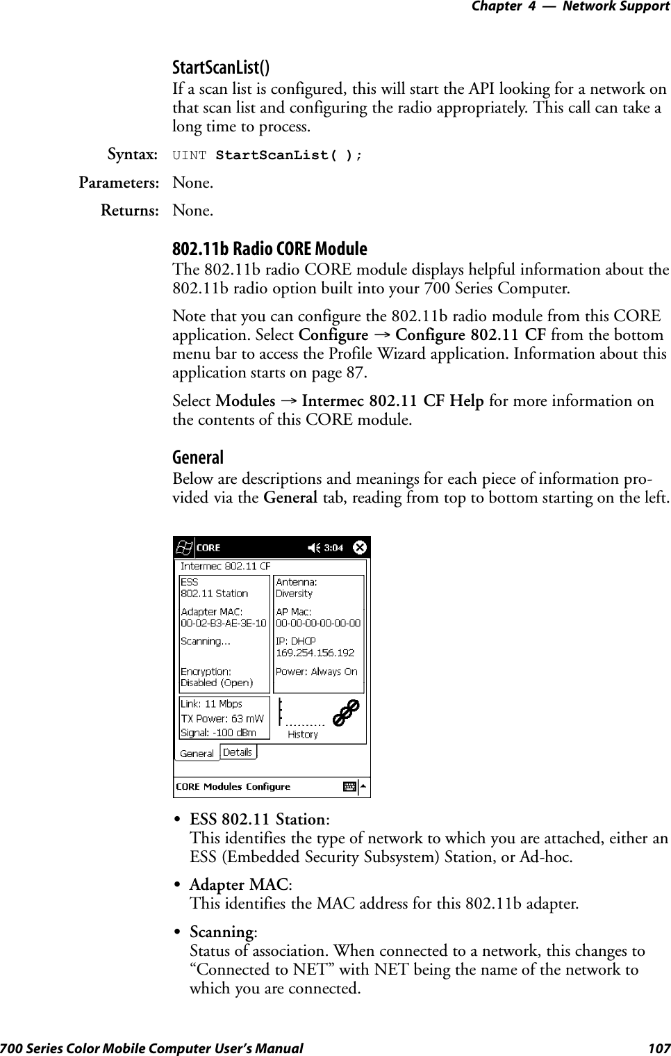
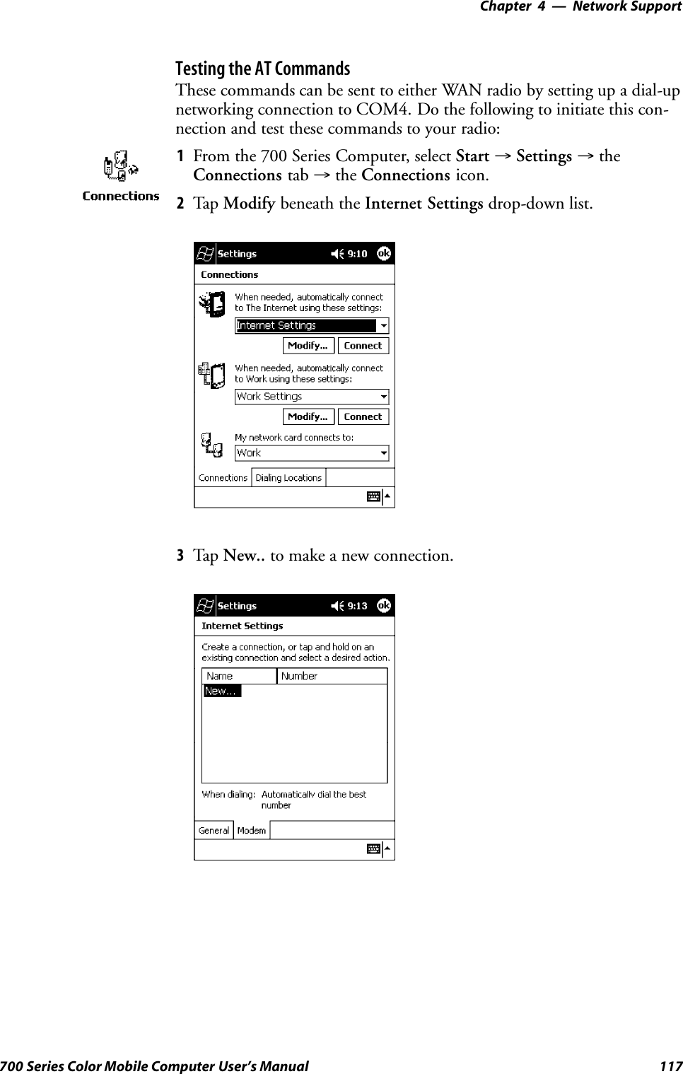
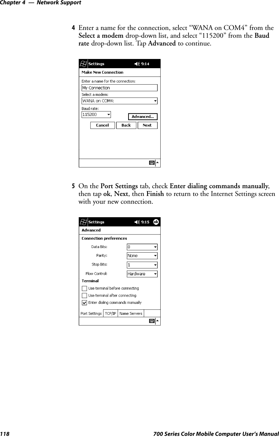
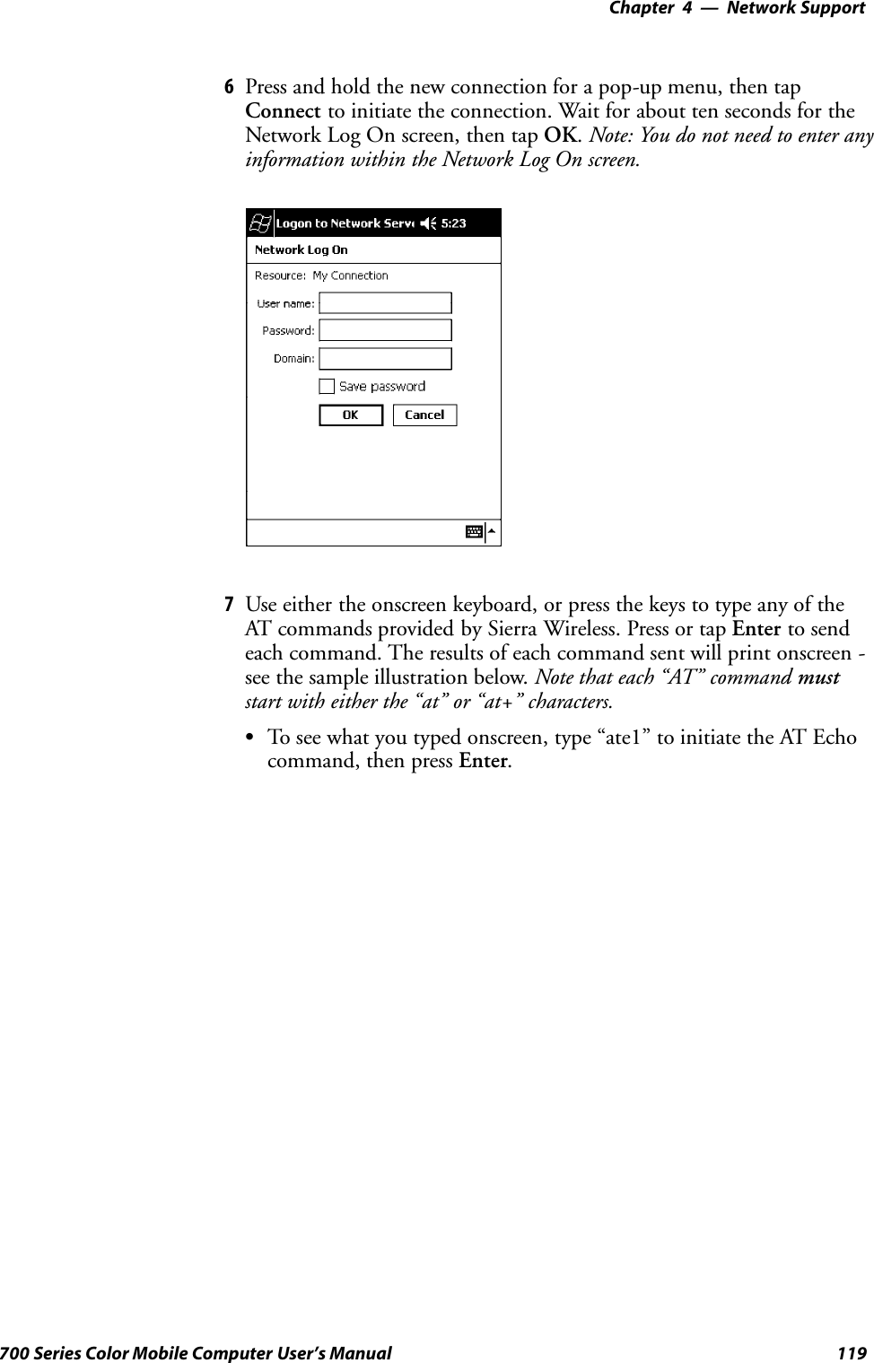
![Network Support—Chapter 499700 Series Color Mobile Computer User’s Manual#include <winioctl.h>#include “sysio.h”void DoLoad(int nDevice) {LPTSTR devs[] = { _T(“SYI1:”), _T(“FWV1:”) };HANDLE hLoaderDev;DWORD bytesReturned;hLoaderDev = CreateFile(devs[nDevice], GENERIC_READ|GENERIC_WRITE, 0,NULL, OPEN_EXISTING, 0, NULL);if (hLoaderDev != INVALID_HANDLE_VALUE) {if (!DeviceIoControl( hLoaderDev, IOCTL_LOAD_NDIS_MINIPORT, NULL, -1, NULL, 0,&bytesReturned, NULL)){MessageBox(NULL, TEXT(“SYSIO IoControl Failed”), TEXT(“Networkloader”),MB_ICONHAND);if (hLoaderDev!=INVALID_HANDLE_VALUE) CloseHandle(hLoaderDev);hLoaderDev = INVALID_HANDLE_VALUE; // bad handle}else {CloseHandle(hLoaderDev);}}}void DoUnload(int nDevice) {LPTSTR devs[] = { _T(“SYI1:”), _T(“FWV1:”) };HANDLE hLoaderDev;DWORD bytesReturned;hLoaderDev = CreateFile(devs[nDevice], GENERIC_READ|GENERIC_WRITE, 0,NULL, OPEN_EXISTING, 0, NULL);if (hLoaderDev != INVALID_HANDLE_VALUE) {if (!DeviceIoControl( hLoaderDev, IOCTL_UNLOAD_NDIS_MINIPORT, NULL, -1, NULL, 0,&bytesReturned, NULL)){MessageBox(NULL, TEXT(“SYSIO IoControl Failed”),TEXT(“Networkloader”),MB_ICONHAND);if (hLoaderDev!=INVALID_HANDLE_VALUE) CloseHandle(hLoaderDev);hLoaderDev = INVALID_HANDLE_VALUE; // bad handle}else {CloseHandle(hLoaderDev);}}}](https://usermanual.wiki/Intermec-Technologies/700C-SMC45.User-Manual-pt-2/User-Guide-301919-Page-25.png)
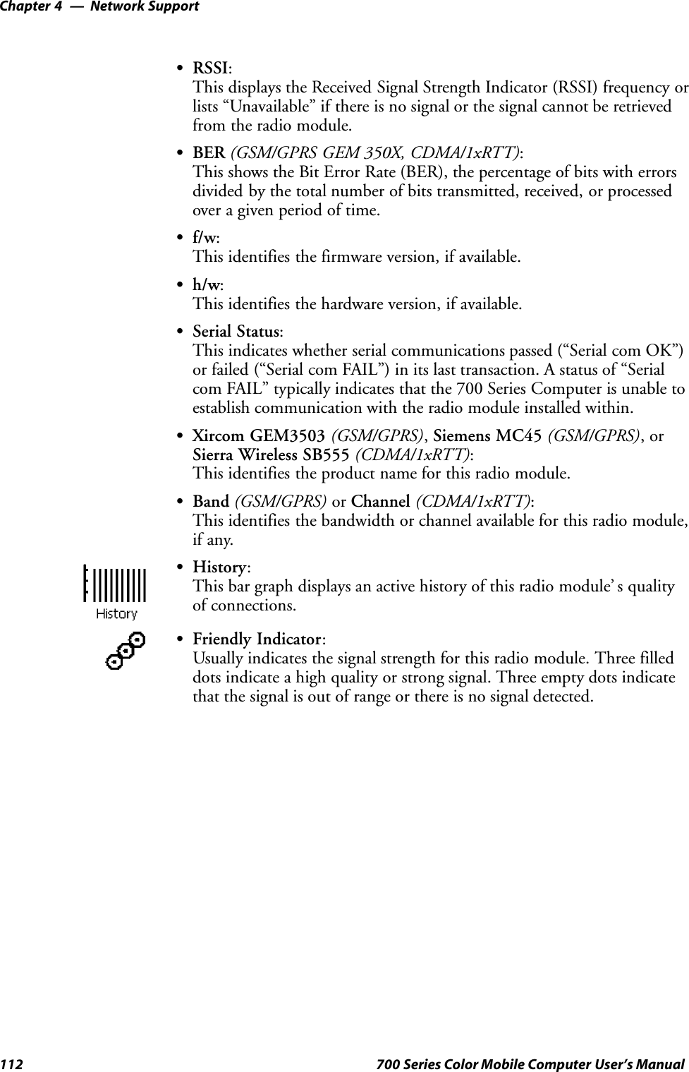
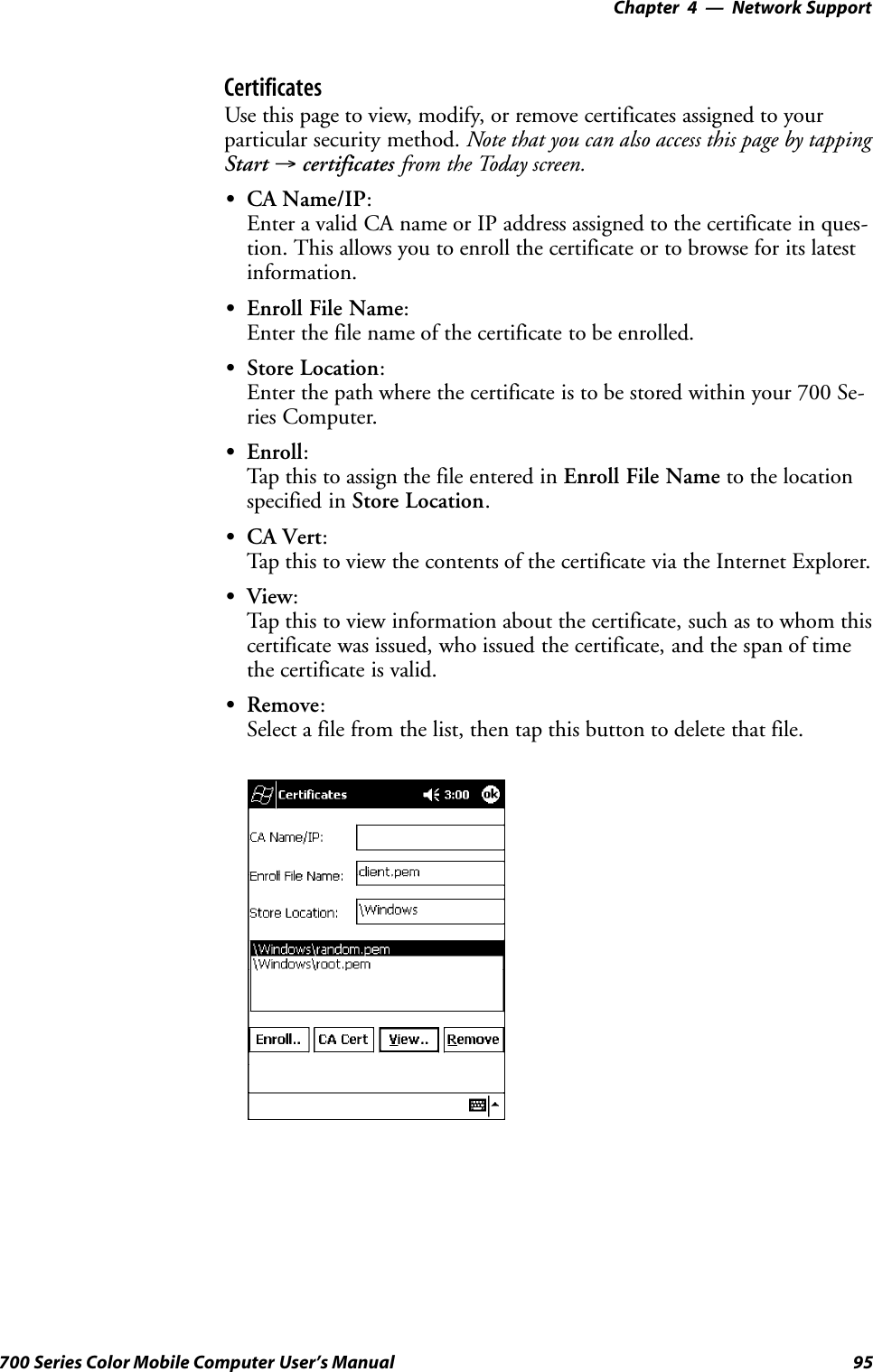
![Network Support—Chapter 4121700 Series Color Mobile Computer User’s ManualSBluetooth Point to Point:This is the network type. “Point to Point” is the type of connection sup-ported as of this publication. Scatternets are not supported. The only sup-ported application is wireless printing to Intermec wireless printers, suchas the 781T Belt-Mount Printer.SDevice Address:This provides the network address, which in this case, will be replacedby the device address of the Bluetooth compatible module within your700 Series Computer. Note that this address is universally unique.SDiscoverable:The following is displayed depending on whether the 700 Series Com-puter is configured to be discoverable:“Gen” Generally discoverable“Lim” Limited discovery“No” Not discoverableSConnectable:This defines whether the 700 Series Computer is able to accept otherdevices with Bluetooth compatible modules connecting to it. “Yes” if theconnection is doable, “No” if not.SBondable:This defines the security element of the 700 Series Computer, which isthe bondable setting. If the unit is bondable, then “Yes” is displayed,otherwise “No” is displayed.SModule Firmware:This reflects the firmware (hardware) version of the 700 Series Comput-er. When the CORE module first installs onto the unit, the firmwarelevel is unknown, thus “...reading” is displayed. Once the firmware levelis read from the unit, then a three-digit decimal is displayed.SStack [Stack Version] [loaded/not loaded]:[Stack Version] displays the Bluetooth stack version, which appears in the“1.2.3.4” format. If the stack is loaded, then “loaded” is displayed afterthe stack version, otherwise “not loaded” is displayed.SDevice Name:This displays the device name as assigned to the Bluetooth compatiblemodule by the end-user. If the configured name is longer than the spaceallowed, it will be truncated.SBTpak Version:This displays the driver version of additional Bluetooth componentswithin the 700 Series Computer and is usually presented in the “1.2.3”format. The version may also contain a letter at either end.SHistory:This bar graph displays an active history of this wireless printer driver’ squality of connections.SFriendly Indicator:If the Bluetooth stack is loaded, then all three dots are filled. These dotsare left empty if the stack is not loaded. These dots do vary based on theCORE application’ s perception of the overall connection quality.](https://usermanual.wiki/Intermec-Technologies/700C-SMC45.User-Manual-pt-2/User-Guide-301919-Page-46.png)