Intermec Technologies 700C-SMC45 Pen-notepad computer with Radio interfaces User Manual back let85x11
Intermec Technologies Corporation Pen-notepad computer with Radio interfaces back let85x11
Contents
User Manual pt 2

75700 Series Color Mobile Computer User’s Manual
Installing Applications
3
There are multiple ways to get an application to your 700 Series Color
Mobile Computer; just as there are multiple ways to package the applica-
tion for delivery.
Installing ApplicationsChapter —3
76 700 Series Color Mobile Computer User’s Manual
Packaging an Application
Use any of the following methods to package an application for installa-
tion:
SFor very simple applications, the application itself might be the only file
that needs to be delivered.
SIt could be a directory structure that contains the application, support-
ing files like ActiveX controls, DLLs, images, sound files, and data files.
SVia a CAB file.
Consider either of the following when choosing a location into which to
store your application:
SIn the basic 700 Series Computer, there are no built-in storage options
other than the Object Store. The Object Store is RAM that looks like a
disk. Anything copied here will be deleted when a cold-boot is per-
formed on the 700 Series Computer.
SIf the optional SecureDigital or CompactFlash storage card is in the sys-
tem, then consider this card the primary location for placing an applica-
tions install files. The following folders represent either card:
SThe SecureDigital storage card creates the “\SDMMC Disk” folder.
SThe CompactFlash storage card creates the “\Storage Card” folder.
SFiles copied to either of these locations will be safe when a cold-boot is
performed on a 700 Series Computer - providing the AutoRun system is
installed onto the storage card. You can find this system on the Recovery
CD. Copying a CAB file to the “\CABFILES” folder on one of these
cards will automatically extract that CAB file on every cold boot to en-
sure that your system is properly set up. See page 82 for more details on
how this works.
Installing Applications
Consider any of the following options to get the package to the preferred
location on your 700 Series Computer.
SMicrosoft ActiveSync
SFTP Server (page 78)
SApplication Manager in Unit Manager (page 78)
SSecureDigital or CompactFlash storage card (page 78)
Installing Applications—Chapter 3
77700 Series Color Mobile Computer User’s Manual
Using Microsoft ActiveSync
Note: These instructions assume that the 700 Color Management Tools
portion of the 700 Series Color Software Tools CD was installed onto your
desktop.
The Microsoft ActiveSync tool is located on the 700C Companion CD,
which contains Microsoft products, such as Outlook and ActiveSync. See
Chapter 2, “Pocket PC 2002,” for information about this tool as provided
by Microsoft Corporation.
This can be a serial, USB, Ethernet, InfraRed, or 802.11b ActiveSync con-
nection. Files can then be copied using File Explorer on a PC or a laptop
computer. This option is usually only good when updating a few 700 Se-
ries Computers.
These instructions assume that Microsoft ActiveSync had been installed
onto your desktop computer and is up and running. If not, go to Chapter
2, “Pocket PC 2002,” for an URL from which you can download the latest
application.
1Connect your 700 Series Computer to your desktop computer via an
ActiveSync cable or IrDA.
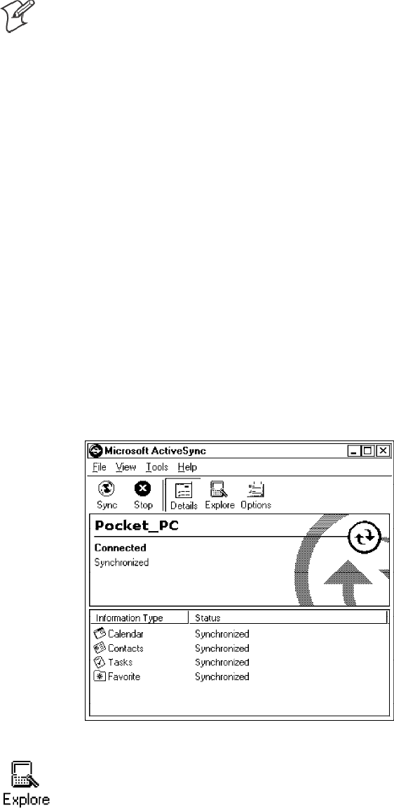
2Wait for a “Connected” message to appear in the Microsoft ActiveSync
application to signal a connection to the 700 Series Computer. If neces-
sary, select File →Get Connected to initiate a connection.
3Click Explore to access the Mobile Device directory on your 700 Series
Computer.
Installing ApplicationsChapter —3
78 700 Series Color Mobile Computer User’s Manual
4From your desktop, select Start →Windows Explorer, then browse the
applicable path for any of the system files needed for your 700 Series
Computer (listed with their paths). Select to highlight the appropriate
file, right-click the file for a pop-up menu, then select Copy.
SBase operating system files:
“C:\Intermec\Intermec 700 Color Mgmt Tools\Drive Images”
SCAB files:
“C:\Intermec\Intermec 700 Color Mgmt Tools\Cab Files”
5Within the Mobile Device directory, go to the directory where you want
the files located on the 700 Series Computer, do a right-click for a pop-
up menu, then select Paste.
6When all of the files are pasted, perform a warm-boot on the 700 Series
Computer. When the computer reboots, wait for the LED on the top
left of your keypad to stop blinking. Tap Start →Programs →File Ex-
plorer to locate the newly copied executable files, then tap these files to
activate their utilities.
Using the FTP Server
The 700 Series Computer has a built-in FTP Server that connects to a net-
work via Ethernet or 802.11b. This “ftp”s to the IP address of the 700 Se-
ries Computer and places files. The benefit of using FTP is that a script
can be created that will automate the process of copying files to the 700
Series Computer. This option is good for when a large number of 700 Se-
ries Computers need to be updated. See Chapter 7, “Programming,” for
more information.
Using the Application Manager in Unit Manager
This requires the 700 Series Computer to connect to the network via
Ethernet or 802.11b. The process is still manual so it would take longer
than the FTP method but it would still be a better option than ActiveSync
where many 700 Series Computers need to be updated. The Unit Manager
applications are available on the 700 Series Color Unit Manager CD-ROM.
For more information, consult your Intermec sales representative.
Using a Storage Card
The following steps pertain to installing an application using a storage
card.
Copying to a CompactFlash Card
Follow the steps below to install your application on the device using a
CompactFlash storage card:
1Suspend the 700 Series Color Mobile Computer and remove its Com-
pactFlash drive, which holds a SanDisk CompactFlash storage card.
2Using a CompactFlash Adapter card, place the CompactFlash Drive in
your desktop PC card drive.
Installing Applications—Chapter 3
79700 Series Color Mobile Computer User’s Manual
3Create a subdirectory on the PCMCIA CompactFlash drive in which to
store your application.
4Add the autorun system to the storage card using the CEImager
application. See the Software Tools User’ s Manual for information about
CEImager.
5Copy your application, data files, and all required DLLs and drivers to
the subdirectory created on the CompactFlash drive.
6Add your application to the AUTOUSER.DAT file on the
“\Storage Card\2577” directory that contains the following statement,
where your directory is the directory on the CompactFlash storage card
where the application was installed, and yourapp.exe is the name of your
application. Finish the “RUN=” statement with a carriage return line-
feed combination. There may be multiple run statements in the file.
RUN=\<your directory>\<yourapp.exe>
7Remove the CompactFlash drive from your desktop computer and rein-
stall it into the 700 Series Computer.
8Warm-boot the 700 Series Computer to add these files to the Compact-
Flash storage card.
If the AUTOUSER.DAT file is found and the “RUN=” statement is cor-
rect, then the task manager will launch and execute your program on start-
up.
Copying to a SecureDigital Storage Card
Do the same steps as for the CompactFlash storage Card, except replace
the “\Storage Card\2577” directory with the “\SDMMC Disk\2577” direc-
tory.
Updating the System Software
You can use the Recovery CD to reinstall or update the operating system
software on the 700 Series Color Computer. For more information, con-
tact your Intermec sales representative.
Installing ApplicationsChapter —3
80 700 Series Color Mobile Computer User’s Manual
Application Migration
Note: These instructions assume that the 700 Color Management Tools
portion of the 700C Software Tools CD was installed onto your desktop
and that a storage card has been added to the base configuration of the 700
Color Computer.
The following steps are required to ensure that the following will happen
on a cold-boot:
SCAB files can be restored,
Sapplications will automatically start,
Sand the registry will be restored.
Do the following for the cold-boot procedure:
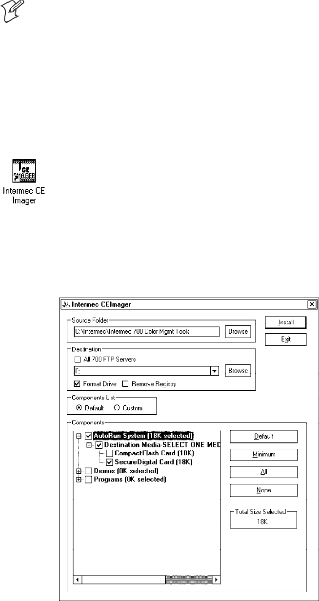
1From your desktop, double-click the Intermec CE Imager desktop icon
to access the Intermec CEImager application. If this icon is not on your
desktop, then double-click the CEIMAGER.EXE executable from the
“C:\Intermec\Intermec 700 Color Mgmt Tools\Tools\CEImager” folder.
2Click Default under Components List to activate the components.
3Click (+) to expand the AutoRun System component, click (+) to ex-
pand the Destination Media option, then select either the Compact-
Flash Card option or the SecureDigital Card option. Do not select both
storage cards, as the AutoRun files copied will work for one storage card, but
not work on the other storage card.
Installing Applications—Chapter 3
81700 Series Color Mobile Computer User’s Manual
4Click Install to install the AUTORUN files onto the storage card.
5Create a “\Cabfiles” folder on the storage card. Copy any CAB files that
are to be extracted on every startup into this folder.
6In the “\2577” directory, add your custom AUTOUSER.DAT file. See
the Recovery Help for more information on how to set up an
AUTOUSER.DAT file.
7If you are using the RegFlushKey() API, the application must use a spe-
cial API to make sure the registry is written to the appropriate card; or
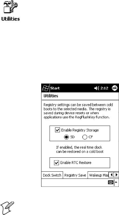
you can use the Utilities control panel applet, as follows:
aFrom the 700 Series Computer, tap Start →Settings →the System
tab →the Utilities icon →the Registry Save tab.
bTap Enable Registry Storage, then tap either of the following:
SSD
To write the registry to the SecureDigital storage card.
SCF
To write the registry to the CompactFlash storage card.
cTap ok to save your entry and exit the Utilities control panel applet.
Note: If you are using a SecureDigital storage card, you must change any
disk access from “Storage Card” to “SDMMC Disk.”
8Remove the storage card from the desktop PC and install the card into
the 700 Series Color Computer.
9Perform a cold-boot on the 700 Series Color Computer. Files will
automatically install from the storage card upon reboot. Any calls to the
RegFlushKey() API will automatically write the registry to the
appropriate location.
Installing ApplicationsChapter —3
82 700 Series Color Mobile Computer User’s Manual
When converting a 700 Series Monochrome Computer application to run
on the 700 Series Color Computer, most APIs should work without chan-
ges. Below are a few exceptions:
SThe 700 Series Monochrome Computer used the “\Storage Card” folder
for nonvolatile storage. You may need to change the application to store
data in a volatile location or onto the “SDMMC Disk” if a SecureDigi-
tal storage card is present in the system.
SIf the application uses the RegFlushKey() API, it must first verify that
the proper media is available in the system and call the special API men-
tioned in Step 7 on the previous page.
SIf the application will be using the 700 Color switchable dock, use the
API to set the proper port on the dock before communications.
SSome WAN radio options have changed. Review the WAN radio section
to determine if any changes will be required in your application.
SThe arrow and tab keys are swapped from the way they were on the 700
Series Monochrome Computers. Keyboard remapping is available on
the 700 Series Color Computer if these keys need to be changed. See
page 79 for more details.
SNo special SDK is needed to compile applications for the Xscale proces-
sor. Targeting the SA1110 processor will create applications that run on
the 700 Series Color Computer.
Cabinet File Installation
CAB files (short for cabinet files) are like .ZIP files, plus they register DLLs,
create shortcuts, modify registry entries, and run custom set up programs.
Tap a CAB file to extract that file or place the CAB file on one of the ap-
proved storage devices in the “\Cab Files” folder, then perform a warm-
boot on the 700 Series Computer. There are two methods available to ex-
tract a CAB file:
STap a CAB file to extract it. When using this method, the CAB file is
automatically deleted when the extraction process is successful, unless
the CAB file is set with the read-only attribute.
SUse the AUTOCAB method where all files are extracted when a cold-
boot is performed on the 700 Series Computer. This AutoCab applica-
tion is on the Recovery CD, see its “Recovery Help” for more informa-
tion.

83700 Series Color Mobile Computer User’s Manual
Network Support
4
The 700 Series Color Mobile Computer can integrate up to three radios in
a single unit, and will automatically install the appropriate software for ra-
dio use when the unit is powered on. The Intermec CORE application
defaults to the most recently used module. If a module has not yet been
used or set, CORE will default to the first module as listed alphabetically.
The following communication options on the 700 Series Computer pro-
vide wired and wireless connectivity:
SOnboard wired Ethernet (standard)
SWireless Local Area Network (LAN)
This 802.11b radio option provides up to 11 Mb/sec throughput.
SWireless Wide Area Network (WAN)
Includes support for GSM/GPRS and CDMA/1xRTT radios.
SWireless Printing
This allows for cable-free communications with peripheral devices, such
as printers, over a ten-meter range. This compatibility is provided via a
Bluetooth qualified module by Socket Communications.
Network SupportChapter —4
84 700 Series Color Mobile Computer User’s Manual
CORE
The Intermec Common Object Resource Environment (CORE) applica-
tion provides a framework for various modules that let you configure and
manage your Intermec products. These modules are software plug-ins that
can be configuration tools, such as the 802.11b radio configuration mod-
ule, or they can provide information on your environment, such as a bat-
tery life module.
CORE is built into the operating system of every 700 Series Computer.
On the 700 Series Computer, tap Start →Programs →the Intermec
CORE icon to access this application.
CORE modules are collections of specific information. This information is
usually related to a particular radio technology, but not always. Each
module can display general and detailed information. Tap the General and
Details tabs near the bottom to switch between general and detailed
information. Note that not all modules will have detailed information.
To learn more about this application, see its online help. Tap Start →
Help from the menu to see the CORE online help.
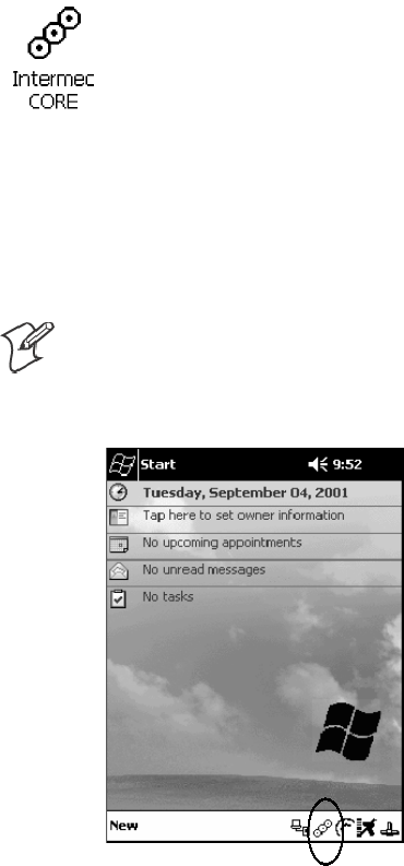
Note: Once CORE is running, you can return to it by tapping its icon
from the System Tray via the Today screen. Tap Start →Today →the
Intermec CORE three-ring icon (circled in the following illustration).
Network Support—Chapter 4
85700 Series Color Mobile Computer User’s Manual
Network Adapters
Your 700 Series Computer can have up to three radios installed. The de-
fault network adapter or radio is dependent on what card is inserted in
your 700 Computer. Below are the the network adapters that exist as of
this publication. See the Developer’ s Support web site for the latest infor-
mation on network adapters for your unit.
SEthernet Communications (LAN9000) - page 86.
S802.11b Radios (802.11b Wireless LAN driver) - page 87.
SWWAN (Wireless WAN) - page 110.
SWireless Printing (PAN) - page 120.
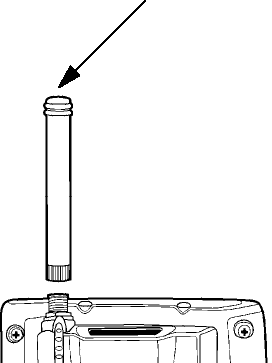
Note that the tip of the antenna attached to your 700 Series Computer is
color-coded to identify its radio type. Refer to the following to determine
your radio type:
SGreen
802.11b diversity
SRed
CDMA/GPRS US/Canada
SBlue
GPRS International
Network SupportChapter —4
86 700 Series Color Mobile Computer User’s Manual
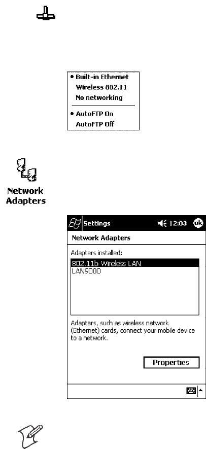
Ethernet Communications
Follow the steps below to start Ethernet communications on the 700 Series
Computer. If your system does not contain an 802.11b radio, then
Ethernet networking using DHCP will be selected as the default.
When “Built-in Ethernet” is selected from the NDISTRY pop-up menu,
then the antenna shown to the left will appear in the System Tray. When
“No networking” is selected, then this icon will appear with a red “X”
above it.
From the 700 Series Computer, tap Start →Settings →the Connections
tab →Network Adapters to access the network connections for this unit.
Make the changes necessary for your network, then tap ok when finished.
Note: “LAN9000” is for Ethernet and ”802.11b Wireless LAN” is for
802.11b radios.
Network Support—Chapter 4
87700 Series Color Mobile Computer User’s Manual
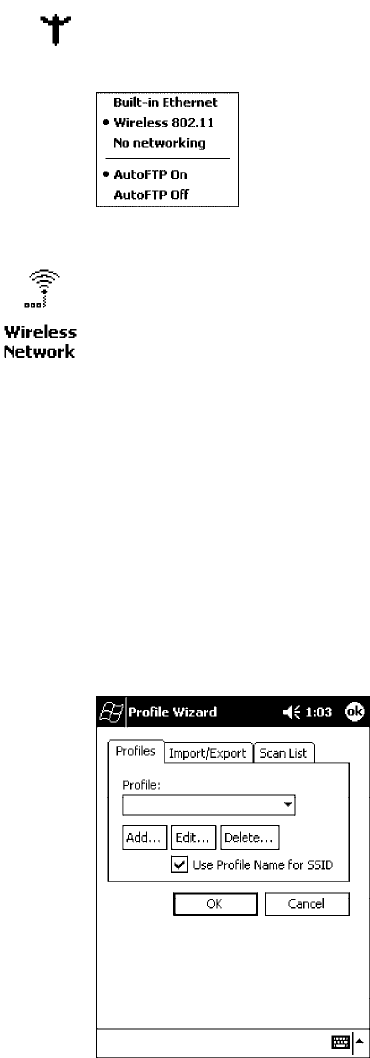
802.11b Communications
The 700 Series Computer can integrate the 802.11b radio module along
with either the GSM/GPRS or the CDMA/1xRTT radio and the Wireless
Printing option. The 802.11b radio module accommodates any Wireless
LAN (WLAN) requirements, such as using WLAN access points for cross-
docking or load-planning applications.
When “Wireless 802.11” is selected via the NDISTRY pop-up menu, then
the antenna shown to the left will appear in the System Tray.
To start 802.11b communications on the 700 Series Computer, tap Start
→Settings →the System tab →the Wireless Network icon to access the
Profile Wizard for the 802.11b radio module. The Profile Wizard defaults
to the Profiles page.
Profiles
Use the Profiles page to add, edit, or delete multiple networking environ-
ments for this 802.11b radio. To add a profile from this screen, enter up to
32 alphanumeric characters in the Profile field, then tap Add.See“Basic”
on page 89 and “Security” on page 90 for more information.
Leave Use Profile Name for SSID checked for the SSID (or Network
Name) to use this profile name. If this is cleared (check mark removed),
the SSID will default to using the factory-assigned “INTERMEC” net-
work name.
Network SupportChapter —4
88 700 Series Color Mobile Computer User’s Manual
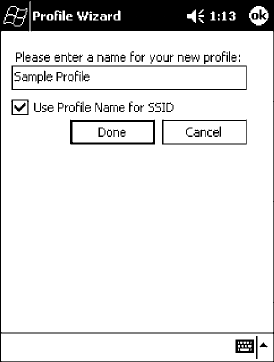
STo add a profile:
Tap Add, enter up to 32 alphanumeric characters to name this profile if
you have not already entered a description in the Profiles page, configu-
re the basic and security information for this profile, then click Done to
configure its basic and security information.
SLeave Use Profile Name for SSID checked for the SSID to use this as-
signed profile name. If this is cleared (check mark removed), the SSID
will default to using the factory-assigned “INTERMEC” network name.
Go to the next page to continue.
STo edit a profile:
Select an existing profile from the Profile drop-down list, tap Edit,
make the changes needed for this profile (starting in the next para-
graph), then tap OK to return to the Profiles page.
STo delete a profile:
Select a profile from the Profile drop-down list, tap Delete,thentapYes
to remove the selected profile.
Network Support—Chapter 4
89700 Series Color Mobile Computer User’s Manual
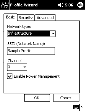
Basic
Use the Basic page to set the network type and radio channel for this pro-
file. Click OK to return to the Profiles page.
SNetwork type:
Tap the drop-down list to select either Infrastructure or Ad-hoc.
SSSID (Network Name):
This assumes the profile name when Use Profile Name for SSID is
checked on the previous screen, unless another name is entered in this
field. If you want to connect to the next available network or are not
familiar with the network name, enter “ANY” in this field. Consult your
LAN administrator for network names.
SChannel:
If “Ad-hoc” were selected as the network type, then this is enabled. Tap
the drop-down list to select a channel, from 1-15, through which to
handle connections (default is 3).
SEnable Power Management:
Check this box to conserve battery power (default), or clear this box to
disable this feature.
Network SupportChapter —4
90 700 Series Color Mobile Computer User’s Manual
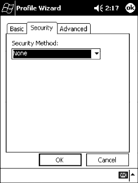
Security
Use the Security page to set this profile as read-only or to enable WEP
(Wired Equivalent Privacy) encryption. Click OK to return to the Profiles
page. The following securities are available from the Security Method
drop-down list. Note that the last three methods are available if you have pur-
chased the security package. Contact your Intermec Representative for more in-
formation.
S802.11 WEP Encryption (next page)
S802.1x TLS (page 92)
S802.1x TTLS (page 93)
SLEAP (page 93)
Network Support—Chapter 4
91700 Series Color Mobile Computer User’s Manual
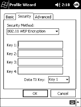
802.11 WEP Encryption:
WEP keys are only needed if they are expected by your clients. There are
two types available: 64-bit (5-character strings, 12345) (default) and
128-bit (13-character strings, 1234567890123). These can be entered as
either ASCII (12345) or Hex (0x3132333435).
To enter WEP keys, select “802.11 WEP Encryption” from the Security
Method drop-down list. Select a data transmission key from the Data TX
Key drop-down list near the bottom of this screen, then enter the encryp-
tion key for that data transmission in the appropriate Key # field.
Network SupportChapter —4
92 700 Series Color Mobile Computer User’s Manual
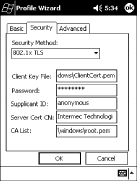
802.1x TLS (Transport Layer Security):
TLS is a protocol that ensures privacy between communicating applica-
tions and their users on the Internet. To use this protocol, select “802.1x
TLS” from the Security Method drop-down list, then enter the following:
SClient Key File:
Enter the file location where the certificate for your identity is stored.
SPassword:
Enter the password for the certificate in this field.
SSupplicant ID:
Enter the user ID associated with this certificate.
SServer Cert CN (Certificate Common Name):
Enter the common name of your authentication server.
SCA List (Certificate Authority):
Enter the file location, or path, of the server certificates.
Network Support—Chapter 4
93700 Series Color Mobile Computer User’s Manual
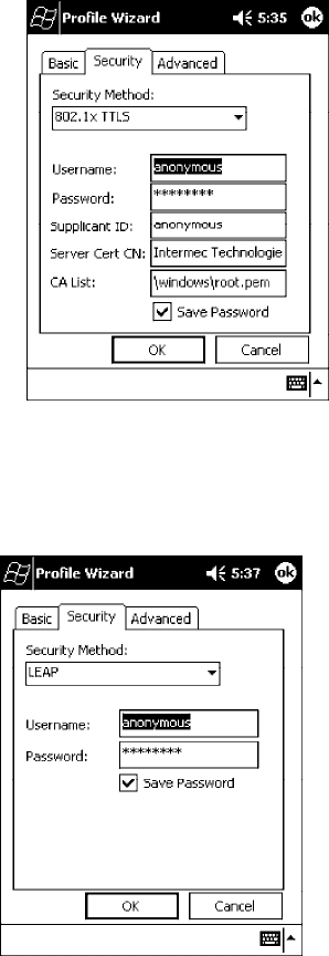
802.1x TTLS (EAP-Tunneled TLS):
To use this protocol, select “802.1x TTLS” from the Security Method
drop-down list, then enter the following:
SUsername:
Enter your user name for this security protocol.
SPassword:
Enter your password for this security protocol.
SSupplicant ID:
Enter “anonymous” unless your administrator indicates otherwise.
SServer Cert CN (Certificate Common Name):
Enter the common name of your authentication server.
SCA List:
Enter the file location, or path, of the server certificates.
LEAP (Cisco Wireless EAP (Extensible Authentication Protocol)):
Enter your unique user name and password to use this protocol.
Network SupportChapter —4
94 700 Series Color Mobile Computer User’s Manual
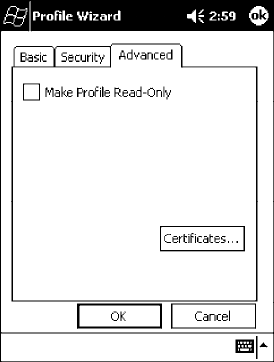
Advanced
Use this page to secure the configuration for this profile or to make all
fields read-only.
SMake Profile Read-Only:
Check this box, then enter and reenter a password to “lock” or render
“read-only” all configurations for this profile. To reverse this step, clear
the check box, then enter the password assigned with the “read-only”
status.
SCertificates:
If “802.1x TLS,” “802.1x TTLS,” or “LEAP” were enabled via the Se-
curity tab, then this button will appear. Tap this button to configure the
available certificates. See “Certificates” on the next page for more infor-
mation.
Network Support—Chapter 4
95700 Series Color Mobile Computer User’s Manual
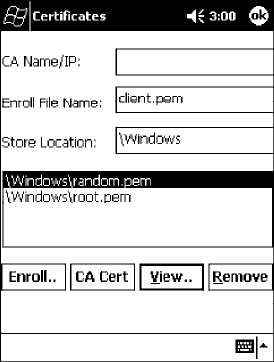
Certificates
Use this page to view, modify, or remove certificates assigned to your
particular security method. Note that you can also access this page by tapping
Start →certificates from the Today screen.
SCA Name/IP:
Enter a valid CA name or IP address assigned to the certificate in ques-
tion. This allows you to enroll the certificate or to browse for its latest
information.
SEnroll File Name:
Enter the file name of the certificate to be enrolled.
SStore Location:
Enter the path where the certificate is to be stored within your 700 Se-
ries Computer.
SEnroll:
Tap this to assign the file entered in Enroll File Name to the location
specified in Store Location.
SCA Vert:
Tap this to view the contents of the certificate via the Internet Explorer.
SView:
Tap this to view information about the certificate, such as to whom this
certificate was issued, who issued the certificate, and the span of time
the certificate is valid.
SRemove:
Select a file from the list, then tap this button to delete that file.
Network SupportChapter —4
96 700 Series Color Mobile Computer User’s Manual
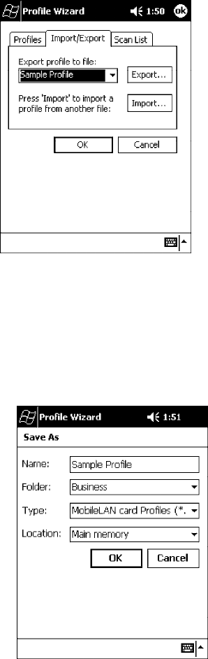
Import/Export
Use this page to send a profile or to retrieve a profile to or from another
location within your 700 Series Computer.
STo export a profile:
Select to highlight a profile, then tap Export. Select from the drop-down
lists, the folder, type of files, and location within the folder where the
profile is to go, tap OK to export the profile, tap ok to close the con-
firmation screen, then tap OK again to exit the Profile Wizard.
Network Support—Chapter 4
97700 Series Color Mobile Computer User’s Manual
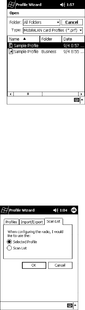
STo import a profile:
Tap Import to access the Open screen, from the drop-down lists, select a
folder and file type, then tap a profile from the list provided. Tap ok to
close the confirmation screen, then tap OK again to exit the Profile
Wizard.
Scan List
Use this Scan List page to monitor network connections, and if lost, to at-
tempt to reestablish connections with these networks.
Selected Profile
Select this option to use the profile defined in the Profiles page, then tap
OK to exit the Profile Wizard. When connections are lost, attempts will be
made to connect to the specified profile.
Network SupportChapter —4
98 700 Series Color Mobile Computer User’s Manual
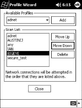
Scan List
Use this option to select a number of profiles with which to establish con-
nections. When connections are lost, attempts will be made to contact each
of the profiles listed, in the order they appear in the list.
1Tap this option, then tap Edit Scan List.
2Select profiles from the Available Profiles drop-down list, then tap Add
to include each selection in the Scan List.
3To arrange the hierarchy of profiles, tap to select a profile, then tap ei-
ther Move Up or Move Down to move each profile. To remove a pro-
file from the list, tap to select that profile, then tap Delete.
4Click either ok or Close to return to the Scan List page, then click OK
to exit the Profile Wizard.
Network Selection APIs
The Network Selection APIs allow the user to change network adapter
configuration programmatically. Both drivers support the same IOCTL
function numbers for loading and unloading the drivers.
Loading and unloading of the 802.11b driver is performed by the FWV1:
device in the system by performing DeviceIOControl() calls to the driver.
Loading and unloading of the driver for the built-in Ethernet adapter is
performed by the SYI1: device in the system by performing DeviceIO-
Control() calls to the driver.
SFor loading an NDIS driver associated with an adapter, the IOCTL is
IOCTL_LOAD_NDIS_MINIPORT.
SFor unloading NDIS drivers associated with an adapter the IOCTL is
IOCTL_UNLOAD_NDIS_MINIPORT.
Network Support—Chapter 4
99700 Series Color Mobile Computer User’s Manual
#include <winioctl.h>
#include “sysio.h”
void DoLoad(int nDevice) {
LPTSTR devs[] = { _T(“SYI1:”), _T(“FWV1:”) };
HANDLE hLoaderDev;
DWORD bytesReturned;
hLoaderDev = CreateFile(devs[nDevice], GENERIC_READ|GENERIC_WRITE, 0,
NULL, OPEN_EXISTING, 0, NULL);
if (hLoaderDev != INVALID_HANDLE_VALUE) {
if (!DeviceIoControl( hLoaderDev, IOCTL_LOAD_NDIS_MINIPORT, NULL, -1, NULL, 0,
&bytesReturned, NULL)){
MessageBox(NULL, TEXT(“SYSIO IoControl Failed”), TEXT(“Network
loader”),MB_ICONHAND);
if (hLoaderDev!=INVALID_HANDLE_VALUE) CloseHandle(hLoaderDev);
hLoaderDev = INVALID_HANDLE_VALUE; // bad handle
}else {
CloseHandle(hLoaderDev);
}
}
}
void DoUnload(int nDevice) {
LPTSTR devs[] = { _T(“SYI1:”), _T(“FWV1:”) };
HANDLE hLoaderDev;
DWORD bytesReturned;
hLoaderDev = CreateFile(devs[nDevice], GENERIC_READ|GENERIC_WRITE, 0,
NULL, OPEN_EXISTING, 0, NULL);
if (hLoaderDev != INVALID_HANDLE_VALUE) {
if (!DeviceIoControl( hLoaderDev, IOCTL_UNLOAD_NDIS_MINIPORT, NULL, -1, NULL, 0,
&bytesReturned, NULL)){
MessageBox(NULL, TEXT(“SYSIO IoControl Failed”),TEXT(“Network
loader”),MB_ICONHAND);
if (hLoaderDev!=INVALID_HANDLE_VALUE) CloseHandle(hLoaderDev);
hLoaderDev = INVALID_HANDLE_VALUE; // bad handle
}else {
CloseHandle(hLoaderDev);
}
}
}
Network SupportChapter —4
100 700 Series Color Mobile Computer User’s Manual
The API provided by Intermec Technologies exposes a limited set of rou-
tines that allows a programmer to access and affect the 802.11b network
interface card from within their application. The routines provided will
also read/write values to the CE registry that pertain to the 802.11b radio
driver. By using the provided functions, a programmer can alter the
802.11b parameters of Network Name (SSID), WEP Keys, Infrastructure
Modes, Radio Channel, and Power Management Modes. A programmer
can also retrieve network connect status and signal strength indication
from the RF network card.
The API is contained within the 80211API.DLL file that should be pres-
ent in any load that has the 802.11b networking installed.
SNETWLAN.DLL
This file is the 802.11b driver. It will be present in all 700 CE loads that
use the 802.11b network interface card.
S80211API.DLL
This file is an Intermec authored file that provides the programmer with
a set of API calls to configure or monitor status of the 802.11b network.
SMOD80211.DLL
The CORE module for the 802.11b NIC. It provides the 802.11b sta-
tus information displayed when the CORE application is running.
S80211CONF.EXE
This is the “Control Panel” for configuring the 802.11b network para-
meters. Note that it is an EXE file and is actually called by
CPL802.CPL (see below). It is also called by the CORE application
when the “Configuration” button is pressed.
SCPL802.CPL
A control panel application that does nothing but call
80211CONF.EXE.
S80211SCAN.EXE
Internally manages the Scan List activity.
The 80211API.DLL supports an unlimited number of radio configuration
profiles. These profiles are the same as those set by the Wireless Network
control panel applet that runs on the Windows CE unit. You can configure
different 802.11b profiles and switch between them using the 802.11 API.
See the ConfigureProfile() function on page 106 for more information.
Network Support—Chapter 4
101700 Series Color Mobile Computer User’s Manual
Function Summary
Below are functions available for the 700 Series Color Computer when
enabled with the 802.11b radio module.
RadioConnect()
Connects to the available radio. Use this function if you plan on using a
lot of API calls that talk directly to the radio.
Syntax: UINT RadioConnect( );
Parameters: None.
Returns: ERROR_SUCCESS when successful, otherwise
ERR_CONNECT_FAILED.
RadioDisconnect()
Cleans up the connection from the RadioConnect() function after an ap-
plication closes.
Syntax: UINT RadioDisconnect( );
Parameters: None.
Returns: ERROR_SUCCESS when successful, otherwise
ERR_CONNECT_FAILED.
GetMac()
Gets the radio MAC address.
Syntax: UINT GetMac( TCHAR * );
Parameters: Pointer to a character array, which is populated with MAC addresses.
Returns: ERROR_SUCCESS when successful,
ERR_QUERY_FAILED when the query failed, or
ERR_CONNECT_FAILED if a connection with the radio failed.
GetBSSID()
Gets the associated access point name, the BSSID.
Syntax: UINT GetBSSID( TCHAR * );
Parameters: Pointer to a character array, which is populated with the current BSSID.
Returns: ERROR_SUCCESS when successful,
ERR_QUERY_FAILED when the query failed, or
ERR_CONNECT_FAILED if a connection with the radio failed
GetSSID()
Gets the current SSID (network name).
Syntax: UINT GetSSID( TCHAR * );
Parameters: Pointer to a character array, which is populated with the current SSID.
Returns: ERROR_SUCCESS when successful,
ERR_QUERY_FAILED when the query failed, or
ERR_CONNECT_FAILED if a connection with the radio failed.
Network SupportChapter —4
102 700 Series Color Mobile Computer User’s Manual
GetLinkSpeed()
Retrieves the current link speed of the radio connection.
Syntax: UINT GetLinkSpeed( int &);
Parameters: &References an integer.
Returns: ERROR_SUCCESS when successful,
ERR_QUERY_FAILED when the query failed, or
ERR_CONNECT_FAILED if a connection with the radio failed.
GetNetworkType()
Retrieves the network type.
Syntax: UINT GetNetworkType( ULONG &);
Parameters: &References a ULONG value, populated with one of the following:
NDIS_NET_TYPE_FH Frequency Hopping Radio
NDIS_NET_TYPE_DS Direct Sequence Radio
NDIS_NET_TYPE_UNDEFINED
Unknown or information not available.
Returns: ERROR_SUCCESS when successful,
ERR_QUERY_FAILED when the query failed, or
ERR_CONNECT_FAILED if a connection with the radio failed.
GetTXPower()
Gets the current TX power of the radio in milliwatts.
Syntax: UINT GetTXPower( ULONG &);
Parameters: &References a ULONG value, populated with one of the following
in milliwatts (mW):
NDIS_POWER_LEVEL_63 63 mW.
NDIS_POWER_LEVEL_30 30 mW.
NDIS_POWER_LEVEL_15 15 mW.
NDIS_POWER_LEVEL_5 5mW.
NDIS_POWER_LEVEL_1 1mW.
NDIS_POWER_LEVEL_UNKNOWN
Unknown Value or Error.
Returns: ERROR_SUCCESS when successful,
ERR_QUERY_FAILED when the query failed, or
ERR_CONNECT_FAILED if a connection with the radio failed.
Network Support—Chapter 4
103700 Series Color Mobile Computer User’s Manual
GetNetworkMode()
Retrieves the network mode.
Syntax: UINT GetNetworkMode( ULONG &);
Parameters: &References a ULONG value, populated with one of the following:
NDIS_NET_MODE_IBSS 802.11 Ad-Hoc Mode.
NDIS_NET_MODE_ESS 802.11 Infrastructure Mode.
NDIS_NET_MODE_UNKNOWN Unknown Value or Error.
NDIS_NET_AUTO_UNKNOWN
Automatic Selection. Use of this option is not recommended.
Returns: ERROR_SUCCESS when successful,
ERR_QUERY_FAILED when the query failed, or
ERR_CONNECT_FAILED if a connection with the radio failed.
SetNetworkMode()
Sets the radio and updates the CE registry.
Syntax: UINT SetNetworkMode( ULONG &);
Parameters: &References a ULONG value, populated with one of the values defined
in GetNetworkMode().
Returns: ERROR_SUCCESS when successful,
ERR_QUERY_FAILED when the query failed, or
ERR_CONNECT_FAILED if a connection with the radio failed.
AddWep()
Adds a WEP key to the radio configuration.
Syntax: UINT AddWep( ULONG 1, BOOL 2, TCHAR * 3);
Parameters: ULONG Pointer that identifies what key to be set.
BOOL Specifies whether the key being set is the default TX key.
TCHAR Pointer that specifies the key data either in hex (string
lengths of 10 or 26) or ASCII (string lengths of 5 or 13).
Returns: ERROR_SUCCESS when successful,
ERR_QUERY_FAILED when the query failed, or
ERR_CONNECT_FAILED if a connection with the radio failed.
GetRSSI()
Sets the current RSSI (Received Signal Strength Indication).
Syntax: UINT GetRSSI( ULONG & );
Parameters: &References a ULONG value.
Returns: ERROR_SUCCESS when successful,
ERR_QUERY_FAILED when the query failed, or
ERR_CONNECT_FAILED if a connection with the radio failed.
Network SupportChapter —4
104 700 Series Color Mobile Computer User’s Manual
GetAssociationStatus()
Gets the current connection, or association status.
Syntax: UINT GetAssociationStatus( ULONG &);
Parameters: &References a ULONG value, a current connection status as follows:
NDIS_RADIO_ASSOCIATED Radio is associated w/access point.
NDIS_RADIO_SCANNING Radio is scanning for network.
Returns: ERROR_SUCCESS when successful,
ERR_QUERY_FAILED when the query failed, or
ERR_CONNECT_FAILED if a connection with the radio failed.
GetWepStatus()
Gets the current WEP status.
Syntax: UINT GetWepStatus( ULONG &);
Parameters: &References a ULONG status value which include the following:
NDIS_RADIO_WEP_ENABLED WEP is currently enabled.
NDIS_RADIO_WEP_DISABLED WEP is currently disabled.
NDIS_RADIO_WEP_ABSENT WEP key is absent.
NDIS_RADIO_WEP_NOT_SUPPORTED
WEP is not supported.
Returns: ERROR_SUCCESS when successful,
ERR_QUERY_FAILED when the query failed, or
ERR_CONNECT_FAILED if a connection with the radio failed.
GetAuthenticationMode()
Gets the current authentication mode.
Syntax: UINT GetAuthenticationMode( ULONG &);
Parameters: &References a ULONG value which include the following current
authentication mode:
NDIS_RADIO_AUTH_MODE_OPEN Open System is in use.
NDIS_RADIO_AUTH_MODE_SHARED Shared Key is in use.
NDIS_RADIO_AUTH_MODE_AUTO Automatic Detection.
NDIS_RADIO_AUTH_MODE_ERROR Unknown value/Error.
Returns: ERROR_SUCCESS when successful,
ERR_QUERY_FAILED when the query failed, or
ERR_CONNECT_FAILED if a connection with the radio failed.
SetAuthenticationMode()
Sets the radio authentication mode with a value defined in the
GetAuthenticationMode() function.
Syntax: UINT SetAuthenticationMode( ULONG );
Parameters: Passes in a ULONG set to one of the values as defined in
GetAuthenticationMode().
Returns: ERROR_SUCCESS when successful,
ERR_QUERY_FAILED when the query failed, or
ERR_CONNECT_FAILED if a connection with the radio failed.
Network Support—Chapter 4
105700 Series Color Mobile Computer User’s Manual
SetChannel()
Sets the radio channel, ranging from 1 to 14.
Syntax: UINT SetChannel( USHORT );
Parameters: USHORT set to a desired channel (1-14).
Returns: ERROR_SUCCESS when successful,
ERR_QUERY_FAILED when the query failed, or
ERR_CONNECT_FAILED if a connection with the radio failed.
EnableWep()
Enables or disables WEP encryption.
Syntax: UINT EnableWep( BOOL );
Parameters: Set to TRUE (0) to enable WEP encryption or FALSE (1) to disabled
WEP encryption.
Returns: ERROR_SUCCESS when successful,
ERR_QUERY_FAILED when the query failed, or
ERR_CONNECT_FAILED if a connection with the radio failed.
GetPowerMode()
Gets the current power management mode of the radio.
Syntax: UINT GetPowerMode( ULONG &);
Parameters: &References a ULONG value which include the following current radio
power management mode:
NDIS_RADIO_POWER_MODE_CAM
Continuous Access Mode (uses most power).
NDIS_RADIO_POWER_MODE_MAX
Maximum Power Savings.
NDIS_RADIO_POWER_MODE_PSP
Power Saving Mode, best balance of power and performance.
NDIS_RADIO_POWER_UNKNOWN
Unknown mode reported or error.
Returns: ERROR_SUCCESS when successful,
ERR_QUERY_FAILED when the query failed, or
ERR_CONNECT_FAILED if a connection with the radio failed.
SetSSID()
Passes the desired SSID (network name).
Syntax: UINT SetSSID( TCHAR * );
Parameters: Pointer to a character array that contains the desired SSID.
Returns: ERROR_SUCCESS when successful,
ERR_QUERY_FAILED when the query failed, or
ERR_CONNECT_FAILED if a connection with the radio failed.
Network SupportChapter —4
106 700 Series Color Mobile Computer User’s Manual
isOrinoco()
Confirms whether the present radio is an ORiNOCO radio.
Syntax: UINT isOrinoco( );
Parameters: None.
Returns: TRUE when an ORiNOCO radio.
FALSE when other than an ORiNOCO radio.
EncryptWepKeyForRegistry()
Encrypts a key for registry storage. Requires TCHAR pointers for a des-
tination and a source.
Syntax: UINT EncryptWepKeyForRegistry( TCHAR * szDest, TCHAR *
szSource );
Parameters: szDest String for the destination.
szSource String for the source.
Returns: ERROR_SUCCESS when successful,
ERR_QUERY_FAILED when the query failed, or
ERR_CONNECT_FAILED if a connection with the radio failed.
SetRTSThreshold()
Sets the radio RTS (Request To Send) threshold.
Syntax: UINT SetRTSThreshold( USHORT &);
Parameters: &References a USHORT value.
Returns: None.
GetRTSThreshold()
Gets the radio RTS threshold.
Syntax: UINT GetRTSThreshold( USHORT &);
Parameters: &References a USHORT value.
Returns: None.
ConfigureProfile()
If using the Intermec 802.11b Profile Management system, you can pro-
gram the API to configure the radio to a specific profile by passing the pro-
file name.
Syntax: UINT ConfigureProfile( TCHAR * );
Parameters: Pointer to a string that contains the name of the profile to be activated.
Returns: None.
Network Support—Chapter 4
107700 Series Color Mobile Computer User’s Manual
StartScanList()
If a scan list is configured, this will start the API looking for a network on
that scan list and configuring the radio appropriately. This call can take a
long time to process.
Syntax: UINT StartScanList( );
Parameters: None.
Returns: None.
802.11b Radio CORE Module
The 802.11b radio CORE module displays helpful information about the
802.11b radio option built into your 700 Series Computer.
Note that you can configure the 802.11b radio module from this CORE
application. Select Configure →Configure 802.11 CF from the bottom
menu bar to access the Profile Wizard application. Information about this
application starts on page 87.
Select Modules →Intermec 802.11 CF Help for more information on
the contents of this CORE module.
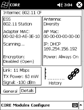
General
Below are descriptions and meanings for each piece of information pro-
vided via the General tab, reading from top to bottom starting on the left.
SESS 802.11 Station:
This identifies the type of network to which you are attached, either an
ESS (Embedded Security Subsystem) Station, or Ad-hoc.
SAdapter MAC:
This identifies the MAC address for this 802.11b adapter.
SScanning:
Status of association. When connected to a network, this changes to
“Connected to NET” with NET being the name of the network to
which you are connected.

Network SupportChapter —4
108 700 Series Color Mobile Computer User’s Manual
SEncryption:
This indicates whether WEP encryption is “Enabled” or “Disabled
(Open).” See page 90 for more information.
SLink:
This indicates the speed at which a connection is made.
STX Power:
This shows the speed (in milliwatts) at which transmissions are made.
SSignal:
This identifies the radio signal strength (in dBm).
SAntenna:
This identifies the antenna being used with the assigned profile.
SAP Mac:
This identifies the MAC address of the access point to which this 700
Series Computer is connected.
SIP:
This provides the IP address which can be set as either DHCP (Dynam-
ic Host Configuration Protocol) or statically.
SPower:
This indicates the power status of this 700 Series Computer: “Always
On” is the default.
SHistory:
This bar graph displays an active history of this radio module’ s quality
of connections.
SFriendly Indicator:
If the radio stack is loaded, then all three dots are filled. These dots are
left empty if the stack is not loaded. These dots do vary based on the
CORE application’ s perception of the overall connection quality.
Network Support—Chapter 4
109700 Series Color Mobile Computer User’s Manual
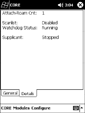
Details
Below are descriptions and meanings for each piece of information pro-
vided via the Details tab, reading from top to bottom.
SAttach-Roam Cnt:
This includes the number of new associations made during the current
session, including any found roaming.
SScanlist:
This indicates whether the Scan List option was enabled or disabled. See
page 97 for more information.
SWatchdog Status:
This monitors the activity of the Scan List: “Running” or “Stopped.”
SSupplicant:
This monitors the 802.1x security activity on the client: “Running” or
“Stopped.”
Network SupportChapter —4
110 700 Series Color Mobile Computer User’s Manual
WWAN Radio Options
The 700 Series Computer can integrate either the GSM/GPRS or the
CDMA/1xRTT radio along with the 802.11b radio and the Wireless
Printing option. The WWAN radio option accommodates any Wireless
WAN requirements, such as taking the 700 Series Computer off the prem-
ises in a delivery vehicle to cover a much larger area.
GSM/GPRS
The GSM (Global System for Mobile communications) and GPRS (Gen-
eral Packet Radio Service) wireless infrastructure increases voice capacity,
enables personalized “user-aware” services, and creates networking efficien-
cies to help wireless service providers drive reduced operating costs.
SGSM is an open, nonproprietary system. One of its great strengths is
the international roaming capability. This provides seamless and same-
standardized same-number contactability world-wide. GSM satellite
roaming has extended service access to areas with unavailable terrestrial
coverage.
SGPRS is the high-speed data evolution of GSM. GPRS supports Inter-
net Protocol (IP), enabling access to Internet and intranet content and
applications from GPRS wireless devices. The anticipated data rate for
GPRS is 115 Kbps and throughput rates of 30-60 Kbps have been
achieved initially. This high speed capability enables vehicle applications
to become real-time and to use the Internet for access to corporate data
or information in the form of traffic or navigation.
CDMA/1xRTT SB555
Code Division Multiple Access (CDMA) is a form of “spread-spectrum,” a
family of digital communication techniques used in military applications
for years. The core principle of spread-spectrum is the use of noise-like
carrier waves, and, as the name implies, bandwidths much wider than that
required for simple point-to-point communication at the same data rate.
S1XRTT, the first phase of CDMA2000, is designed to support up to
144 KB per second packet data transmission and to double the voice
capacity of current generation CDMA networks.
SSB555 Embedded Module, from Sierra Wireless, provides complete
wireless functionality and integrates easily into the most compact and
slender mobile applications with its small flexible design. The SB555
offers maximum coverage and access to entire CDMA networks.
Network Support—Chapter 4
111700 Series Color Mobile Computer User’s Manual
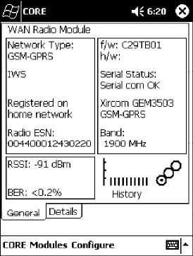
WAN Radio CORE Module
The WAN radio CORE module displays helpful information about either
the GSM/GPRS radio or the CDMA/1xRTT radio option built into your
700 Series Computer. The following illustrations are for a GSM/GPRS
GEM350X radio.
General
Below are descriptions and meanings for each piece of information pro-
vided via the General tab, reading from top to bottom starting on the left.
The information applies to both the GSM/GPRS and the CDMA/1xRTT ra-
dio modules unless otherwise indicated.
SNetwork Type:
This is the network type which would list either “GSM-GPRS” or
“CDMA-1XRTT.” Scatternets are not supported.
SIWS (GSM/GPRS) or Sprint PCS Network (CDMA/1xRTT):
This lists the name of the wireless network provider, such as T-Mobile,
Voicestream, AT&T Wireless, etc. “IWS” is short for the Iowa Wireless
Service carrier.
SRegistered on home network:
If the WAN radio module has registered with a service provider net-
work, then one of the following will appear:
SRegistered on home network:
The radio module is registered on its “home” network.
SRegistered on roamed network:
The radio module is registered on another service provider’ s network.
SRadio Not Registered:
There is no network within range of this radio module.
SRadio ESN:
This displays the Electronic Serial Number (ESN) assigned to this radio
module or lists “Unavailable” if a number cannot be read from the ra-
dio.

Network SupportChapter —4
112 700 Series Color Mobile Computer User’s Manual
SRSSI:
This displays the Received Signal Strength Indicator (RSSI) frequency or
lists “Unavailable” if there is no signal or the signal cannot be retrieved
from the radio module.
SBER (GSM/GPRS GEM 350X, CDMA/1xRTT):
This shows the Bit Error Rate (BER), the percentage of bits with errors
divided by the total number of bits transmitted, received, or processed
over a given period of time.
Sf/w:
This identifies the firmware version, if available.
Sh/w:
This identifies the hardware version, if available.
SSerial Status:
This indicates whether serial communications passed (“Serial com OK”)
or failed (“Serial com FAIL”) in its last transaction. A status of “Serial
com FAIL” typically indicates that the 700 Series Computer is unable to
establish communication with the radio module installed within.
SXircom GEM3503 (GSM/GPRS),Siemens MC45 (GSM/GPRS),or
Sierra Wireless SB555 (CDMA/1xRTT):
This identifies the product name for this radio module.
SBand (GSM/GPRS) or Channel (CDMA/1xRTT):
This identifies the bandwidth or channel available for this radio module,
if any.
SHistory:
This bar graph displays an active history of this radio module’ s quality
of connections.
SFriendly Indicator:
Usually indicates the signal strength for this radio module. Three filled
dots indicate a high quality or strong signal. Three empty dots indicate
that the signal is out of range or there is no signal detected.
Network Support—Chapter 4
113700 Series Color Mobile Computer User’s Manual
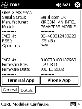
Details
Below are descriptions and meanings for each piece of information pro-
vided via the Details tab, reading from top to bottom. Most of this is simi-
lar to what is shown under the General tab. The information applies to both
the GSM/GPRS and the CDMA/1xRTT radio modules unless otherwise indi-
cated.
SSerial Status:
This indicates whether serial communications passed (“PASS”) or failed
(“FAIL”) in its last transaction. A status of “FAIL” typically indicates
that the 700 Series Computer is unable to establish communication
with the radio module installed within.
SManufacturer:
This lists the name of the manufacturer that developed this radio mod-
ule, such as “Xircom, an Intel Corporation,” “Siemens,” or “Sierra Wire-
less.”
SModel:
This identifies the product name for this radio module, such as
“SB555,” “GEM350X,” or “MC45.”
SIMEI # (GSM/GPRS):
This is the IMEI (International Mobile station Equipment Identity) se-
rial number of the GSM/GPRS radio module.
SRSSI:
This displays the RSSI frequency or lists “Unavailable” if there is no sig-
nal or the signal cannot be retrieved from the radio module.
SOperator:
This lists the name of the service providing the network support.
SSIM Status (GSM/GPRS MC45):
Identifies whether a Subscriber Identity Module (SIM) card is installed
in this 700 Series Computer.
Network SupportChapter —4
114 700 Series Color Mobile Computer User’s Manual
SBand (CDMA/1xRTT):
This identifies the frequency bands used by this radio module.
SIMSI # (GSM/GPRS):
This shows the IMSI (International Mobile Subscriber Identity) number
assigned to the SIM card installed in this 700 Series Computer.
SRadio Temp (CDMA/1xRTT):
This identifies the temperature of the radio module, or lists “Unavail-
able degrees” if there is no information or the temperature cannot be
measured.
SFirmware Rev:
This identifies the firmware version, if available.
SFirmware Date (GSM/GPRS):
This provides the last date when this firmware was updated, if available.
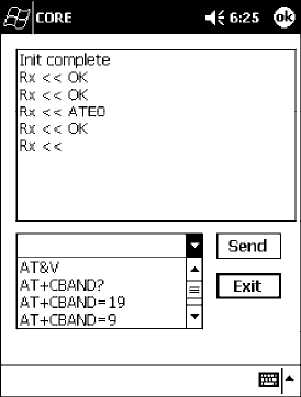
Terminal Application
Tap Terminal App from the Details page to send standard AT commands.
Information about these AT commands are available under “AT Command
Interface” on page 115.
Select an AT command from the drop-down list, then tap Send. The re-
sults of each test appears in the text box. Tap Exit or ok to close this screen
and return to the Details page.

Network SupportChapter —4
116 700 Series Color Mobile Computer User’s Manual
Note: You will need the Adobe Acrobat Reader application to view a PDF
document.Goto“http://www.adobe.com/prodindex/acrobat/readstep.html”
to install or download the latest Adobe Acrobat Reader according to
Adobe’ s instructions.
Command Set for Sierra Wireless SB555
Use the AT command interface from Sierra Wireless to program the
CDMA/1xRTT SB555 radio module. Documentation for this interface is
available via the following URL. Click the “General AT command refer-
ence” link for a PDF document, which is 680 KB in size. Note that this
URL is subject to change.
http://www.sierrawireless.com/ProductsOrdering/embedded_docs.html
Command Set for Xircom/Intel GEM350X
Use the GEM350X AT command list from Intel Corporation to program
the GPRS/GSM GEM350X radio module. The “GEM350X Programmer’ s
Reference” is available either from Intermec Technologies or from Intel
Corporation. Contact either your Intermec representative or the Intel Cor-
poration support personnel at the following URL for more information.
Note that this URL is subject to change.
http://support.intel.com/sites/support/index.htm?iid=intelhome1+support&
Command Set for Siemens MC45
Use the MC45 AT command interface from Siemens AG to program the
GPRS/GSM MC45 radio module. The “MC45 Siemens Cellular Engine
AT Command Set” is available either from Intermec Technologies or from
Siemens AG. Contact either your Intermec representative or the Siemens
AG support personnel at the following URL for more information. Note
that this URL is subject to change.
http://www.siemens-mobile.com/btob/CDA/presentation/ap_btob_cda_presentation_fron
tdoor/0,2950,12,FF.html
Network Support—Chapter 4
117700 Series Color Mobile Computer User’s Manual
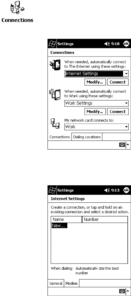
Testing the AT Commands
These commands can be sent to either WAN radio by setting up a dial-up
networking connection to COM4. Do the following to initiate this con-
nection and test these commands to your radio:
1From the 700 Series Computer, select Start →Settings →the
Connections tab →the Connections icon.
2Tap Modify beneath the Internet Settings drop-down list.
3Tap New.. to make a new connection.
Network SupportChapter —4
118 700 Series Color Mobile Computer User’s Manual
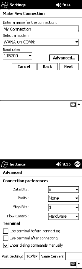
4Enter a name for the connection, select “WANA on COM4” from the
Select a modem drop-down list, and select “115200” from the Baud
rate drop-down list. Tap Advanced to continue.
5On the Port Settings tab, check Enter dialing commands manually,
then tap ok,Next, then Finish to return to the Internet Settings screen
with your new connection.
Network Support—Chapter 4
119700 Series Color Mobile Computer User’s Manual
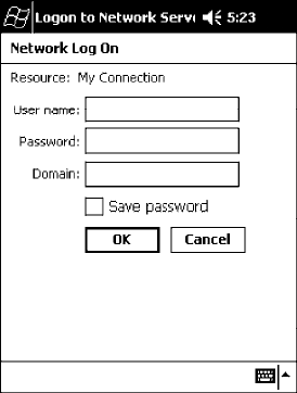
6Press and hold the new connection for a pop-up menu, then tap
Connect to initiate the connection. Wait for about ten seconds for the
Network Log On screen, then tap OK.Note: You do not need to enter any
information within the Network Log On screen.
7Use either the onscreen keyboard, or press the keys to type any of the
AT commands provided by Sierra Wireless. Press or tap Enter to send
each command. The results of each command sent will print onscreen -
see the sample illustration below. Note that each “AT” command must
start with either the “at” or “at+” characters.
STo see what you typed onscreen, type “ate1” to initiate the AT Echo
command, then press Enter.
Network SupportChapter —4
120 700 Series Color Mobile Computer User’s Manual
Wireless Printing
The 700 Series Computer can integrate the Wireless Printing option
(which is equipped with a Bluetooth qualified module by Socket Communica-
tions) along with either the GSM/GPRS or the CDMA/1xRTT radio and
the 802.11b radio. This option uses the network to print information
stored on the 700 Series Computer.
“Bluetooth” is the name given to a technology standard using short-range
radio links, intended to replace the cables connecting portable and fixed
electronic devices. The standard defines a uniform structure for a wide
range of devices to communicate with each other, with minimal user ef-
fort. Its key features are robustness, low complexity, low power, and low
cost. The technology also offers wireless access to LANs, the mobile phone
network, and the internet for a host of home appliances and portable
hand-held interfaces.
Documentation
Information about additional “Bluetooth” software, including the Blue-
tooth Device Manager and the BTctrl program, can be found within the
Wireless Printing SDK. This is located on the 700C Software Tools CD,
via the directory off the root of the toolkit called “Wireless Printing SDK.”
It also can be found in the Wireless Printing Development Guide,alsoonthe
700C Tools CD.
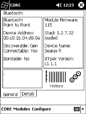
Bluealps CORE Module
The Bluealps CORE module displays helpful information about this Wire-
less Printing option within your 700 Series Computer. Below are descrip-
tions and meanings for each piece of information provided via the General
tab, reading from top to bottom starting on the left.

Network Support—Chapter 4
121700 Series Color Mobile Computer User’s Manual
SBluetooth Point to Point:
This is the network type. “Point to Point” is the type of connection sup-
ported as of this publication. Scatternets are not supported. The only sup-
ported application is wireless printing to Intermec wireless printers, such
as the 781T Belt-Mount Printer.
SDevice Address:
This provides the network address, which in this case, will be replaced
by the device address of the Bluetooth compatible module within your
700 Series Computer. Note that this address is universally unique.
SDiscoverable:
The following is displayed depending on whether the 700 Series Com-
puter is configured to be discoverable:
“Gen” Generally discoverable
“Lim” Limited discovery
“No” Not discoverable
SConnectable:
This defines whether the 700 Series Computer is able to accept other
devices with Bluetooth compatible modules connecting to it. “Yes” if the
connection is doable, “No” if not.
SBondable:
This defines the security element of the 700 Series Computer, which is
the bondable setting. If the unit is bondable, then “Yes” is displayed,
otherwise “No” is displayed.
SModule Firmware:
This reflects the firmware (hardware) version of the 700 Series Comput-
er. When the CORE module first installs onto the unit, the firmware
level is unknown, thus “...reading” is displayed. Once the firmware level
is read from the unit, then a three-digit decimal is displayed.
SStack [Stack Version] [loaded/not loaded]:
[Stack Version] displays the Bluetooth stack version, which appears in the
“1.2.3.4” format. If the stack is loaded, then “loaded” is displayed after
the stack version, otherwise “not loaded” is displayed.
SDevice Name:
This displays the device name as assigned to the Bluetooth compatible
module by the end-user. If the configured name is longer than the space
allowed, it will be truncated.
SBTpak Version:
This displays the driver version of additional Bluetooth components
within the 700 Series Computer and is usually presented in the “1.2.3”
format. The version may also contain a letter at either end.
SHistory:
This bar graph displays an active history of this wireless printer driver’ s
quality of connections.
SFriendly Indicator:
If the Bluetooth stack is loaded, then all three dots are filled. These dots
are left empty if the stack is not loaded. These dots do vary based on the
CORE application’ s perception of the overall connection quality.

Network SupportChapter —4
122 700 Series Color Mobile Computer User’s Manual
AutoIP/DHCP
Automatic Private IP Addressing (AutoIP) is enabled by default in Pocket
PC 2002. To remain compatible with other Pocket PC devices, this setting
needs to be enabled. You can configure the registry settings in the
following to set the required AutoIP/DHCP behavior:
SFor Ethernet: HKEY_LOCAL_MACHINE\Comm\LAN9001\TcpIp
SFot 802.11b: HKEY_LOCAL_MACHINE\Comm\NETWLAN1\TcpIp
Other registry keys that can modify the behavior of AutoIP are as follows.
You can find the appropriate settings and behavior of each of these keys in
Microsoft Help.
SAutoInterval
SAutoMask
SAutoSubnet
SAutoIP
SAutoSeed
When a TCP/IP client cannot find a DHCP server, it generates an AutoIP
address from the 169.254.xxx.xxx block. The client then tries to check for
a DHCP server every 300 seconds (5 minutes) and if a DHCP server is
found, the client drops the AutoIP address and uses the address from the
DHCP server.
In the MSDN Windows CE documentation, see “Automatic Client Config-
uration” for more information on AutoIP.
To disable AutoIP, set the AutoCfg registry entry to “0.” If a DHCP server
cannot be found, instead of using AutoIP, the system will display the “Un-
able to obtain a server assigned IP address” message.
Note: If AutoIP is defined using CAB files, the EnableDHCP registry key
must also be defined and set to “1” before the system will attempt to ob-
tain a DHCP address.
To extend the number of attempts that a DHCP client makes to get a
DHCP address, use the DhcpRetryDialogue and DhcpMaxRetry registry
settings.
Change the AutoInterval registry key value to make the client retry more
often to obtain a DHCP address.
Network Support—Chapter 4
123700 Series Color Mobile Computer User’s Manual
SNMP Configuration
Simple Network Management Protocol (SNMP) was developed in the late
1980s to provide a general-purpose internetworking management protocol.
Its primary goal was to be simple so nothing would stand in the way of its
ubiquitous deployment. To this end, it has been very successful as it is cur-
rently deployed in almost every major internetworking product on the
market. However, like many achieved goals, the primary strength can also
become a weakness.
The Focus was “Simple”
An extreme example of simplicity versus power can be realized by compar-
ing SNMP against the Common Management Information Protocol
(CMIP), the ISO entry to the standard management protocol world.
CMIP has a very rich set of primitives and a core set of data elements.
However, to implement CMIP, a subset of the protocol must be selected.
Then, to achieve interoperability, this subset must be agreed upon with
other implementors. As SNMP was specified completely and with no op-
tions, one implemented what was there and interoperability was assured.
Returning to simplicity, SNMP was built simply for a number of reasons
other than time to market: robustness in the face of network failure, low
overhead in the devices running the protocol; and ease of debugging the
protocol itself (the last thing you want to debug is the management protocol
that is supposed to be helping you debug your network). Thus, the SNMP
limited itself to the User Datagram Protocol (UDP). This gave the
implementor the ability and responsibility to manage lost packets and
perform any necessary retransmissions. As network debugging in the face
of changing routes will certainly mean losing packets, retaining this control
from the transport service (layer 4) was considered essential. Since a
network management protocol will run continuously, it is mandatory that
it consume as minimal a network resource as possible. UDP allows the
necessary control over packet transmissions, packet size and content
(packetization). It is a natural choice.
Using SNMP
SNMP has three control primitives that initiate data flow from the
requester (get, get-next, and set). There are two control primitives the
responder uses to reply. One is used in response to the requester’ s direct
query (get-response) and the other is an asynchronous response to obtain
the requester’ s attention (trap). All five of these primitives are carried by
UDP and are thus limited in size by the amount of data that can fit into a
single UDP packet. The relatively small message size was a goal of the
design but for some reasonable set of network management functions, it
imposes a limitation.
Often in network management, it is necessary to obtain bulk information
without knowing at first what is in that bulk. In one case, there is a set of
problems having to do with packets not going where they are supposed to,
due to device misconfiguration that prevents proper protocol operation
where one needs to view the entire set of data.
Network SupportChapter —4
124 700 Series Color Mobile Computer User’s Manual
Retrieval of Management Information
SNMP has the get-next primitive which permits the viewing of data
without requiring prior knowledge. If you know what you are looking for,
the get primitive will return it. When you want an entire table of
information, the get-next primitive will obtain it. However, unless
employed with care, the get-next primitive can be extremely
resource-intensive in real time, network bandwidth, and the agent’ s CPU
time. The simplest use of the get-next primitive is to start at the beginning
of a table, await the response and then issue another get-next with the
name returned. As an example, say you wanted the next-hop address,
next-hop interface, and route-type from a routing table containing 1000
entries. Using the simplest form of get-next, this would require 2x3x1000
or 6000 packets (get-next and get-response packets, columns, and rows).A
straight-forward optimization would be to request the three columns in a
single packet. This puts the number of packets at 2x1000 or 2000 packets.
In real time, it is the product of the round trip by the number of request.
In agent CPU time, this is still 6000 lookups in the routing table for both
cases.
An Early Approach to Getting More than One Item at a Time
The ability to retrieve only one piece or object at a time has been a
problem for SNMP. This is particularly an issue with the use of this
protocol in wireless environments where the wireless datapipe is small and
overhead due to network management it is considered overhead. One
approach creates multiple get-next requests running concurrently. A second
algorithm, reduces the packet count by combining the multiple concurrent
get-nexts into a single packet. Neither approach has been implemented
which makes network management in wireless environment, though
essential to the success of the operation, tenuous. The issue has been
resolved in SNMP V2 protocol where a get-bulk primitive has been
defined.
Conclusion
Software development moves forward by evolving the unknown into the
known and wireless environments are moving from vertical only
application to wide spread implementation. At the time of the SNMP
inception, it was not possible to conceive of a reliable transport based
network management protocol. Today’ s problems require more
sophisticated data to analyze a problem. This puts the burden back on the
protocol to send and receive data quickly and efficiently. Work continues
in subcommittees to improve SNMP and resolve the issues that are
developing with new applications and new network architectures.

Network Support—Chapter 4
125700 Series Color Mobile Computer User’s Manual
SNMP Configuration on the 700 Series Computer
In short, SNMP is an application-layer protocol that facilitates the ex-
change of management information between network devices. The 700
Series Computer is such an SNMP-enabled device. Use SNMP to control
and configure the 700 Series Computer anywhere on an SNMP-enabled
network.
The 700 Series Computer supports four proprietary Management Infor-
mation Bases (MIBs) and Intermec Technologies provides SNMP support
for MIB-II through seven read-only MIB-II (RFC1213-MIB) Object
Identifiers (OIDs).
Note: You can only query these seven OIDs through an SNMP manage-
ment station, these are not available in the Unit Manager applications.
Management Information Base
The Management Information Base is a database that contains information
about the elements to be managed. The information identifies the manage-
ment element and specifies its type and access mode (Read-Only, Read-
Write). MIBs are written in ASN.1 (Abstract Syntax Notation.1) - a ma-
chine independent data definition language. Note: Elements to be managed
are represented by objects. The MIB is a structured collection of such objects.
You will find the following MIB files either on the 700C Tools CD or on
the web via http://www.intermec.com:
SINTERMEC.MIB
Defines the root of the Intermec MIB tree.
SITCADC.MIB
Defines objects for Automated Data Collection (ADC), such as bar code
symbologies.
SITCSNMP.MIB
Defines objects for Intermec SNMP parameters and security methods,
such as an SNMP security IP address.
SITCTERMINAL.MIB
Defines objects for 700 Series parameters, such as key clicks.

Network SupportChapter —4
126 700 Series Color Mobile Computer User’s Manual
Object Identifiers
Each object has a unique identifier called an OID. OIDs consist of a se-
quence of integer values represented in dot notation. Objects are stored in
a tree structure. OIDs are assigned based on the position of the object in
the tree. Seven MIB OIDs are shown in the followig table.
Example
The internet OID = 1.3.6.1.
MIB Object Identifiers
MIB-II Item OID Group or Table Description
ifNumber 1.3.6.1.2.1.2.1.0 Interfaces Group Indicates the number of adapters
present in the system. For the 700
Series Computer, if one adapter is
present in the system, then ifNum-
ber =1andifIndex=1.
ifIndex 1.3.6.1.2.1.2.2.1.1.ifIndex Inter face s Ta ble (i fTable ) A unique value for each interface.
The value ranges between 1 and the
value of ifNumber.
ifDescr 1.3.6.1.2.1.2.2.1.2.ifIndex Interfaces Table (ifTable) A textual string containing informa-
tion about the interface.
ifType 1.3.6.1.2.1.2.2.1.3.ifIndex Interfaces Ta ble (if Table ) An integer containing information
about the type of the interface. It is
equal to 1 for Other.
ipAdEntAddr 1.3.6.1.2.1.4.20.1.1.IpAddress IP address Table
(ipAddrTable)
The IP address to which this entry’ s
addressing information pertains
(same as 700 IP address), where IP
Address is the valid non-zero IP ad-
dress of the 700 Series Computer.
ipAdEntIfIndex 1.3.6.1.2.1.4.20.1.2.IpAddress IP address Table
(ipAddrTable)
The index value that uniquely iden-
tifies the interface to which this
entry is applicable (same as ifIndex).
ipAdEntNetMask 1.3.6.1.2.1.4.20.1.3.IpAddress IP address Table
(ipAddrTable)
The subnet mask associated with
the IP address of this entry (same as
Subnet Mask).
Configuring with SNMP
The community string allows an SNMP manager to manage the 700 Series
Computer with a specified privilege level. The default read-only communi-
ty string is “public” and “private” is the default read/write community
string. See the specific configuration parameter to find its OID. To config-
ure the 700 Series Computers using SNMP:
1Configure 700 Series Computers for RF or Ethernet communications.
2Determine the OID (Object Identifier) for the parameter to be chan-
ged. The Intermec base OID is 1.3.6.1.4.1.1963.
3Use your SNMP management station to get and set variables that are
defined in the Intermec MIBs. You can set the traps, identification, or
security configuration parameters for SNMP. See Appendix A, “Control
Panel Applets,” to learn more about these parameters.