Intermec Technologies 802MIAG-CV60 802MIAG-CV60 User Manual BeforeYouBegin
Intermec Technologies Corporation 802MIAG-CV60 BeforeYouBegin
UserManual.wiki
>
Intermec Technologies
>
802MIAG CV60 User Manual
Users Manual
Navigation menu
Upload a User Manual
Namespaces
Wiki Guide
HTML
PDF
Info
Views
User Manual
Discussion / Help
Navigation
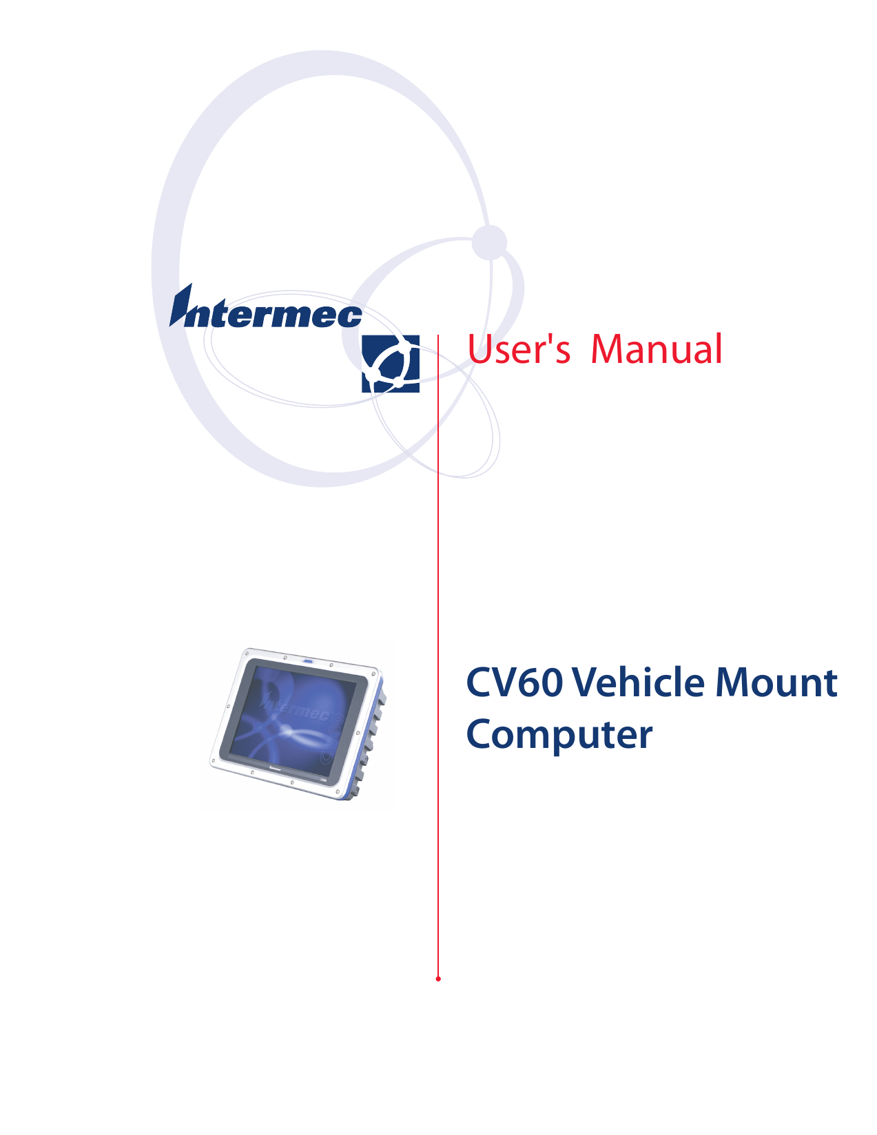

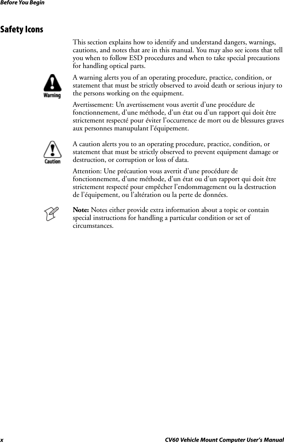
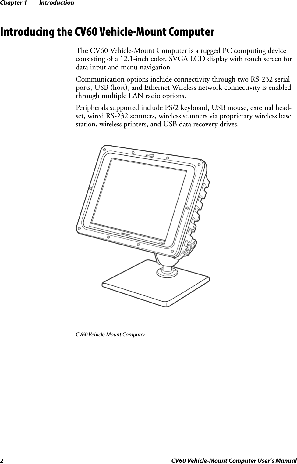
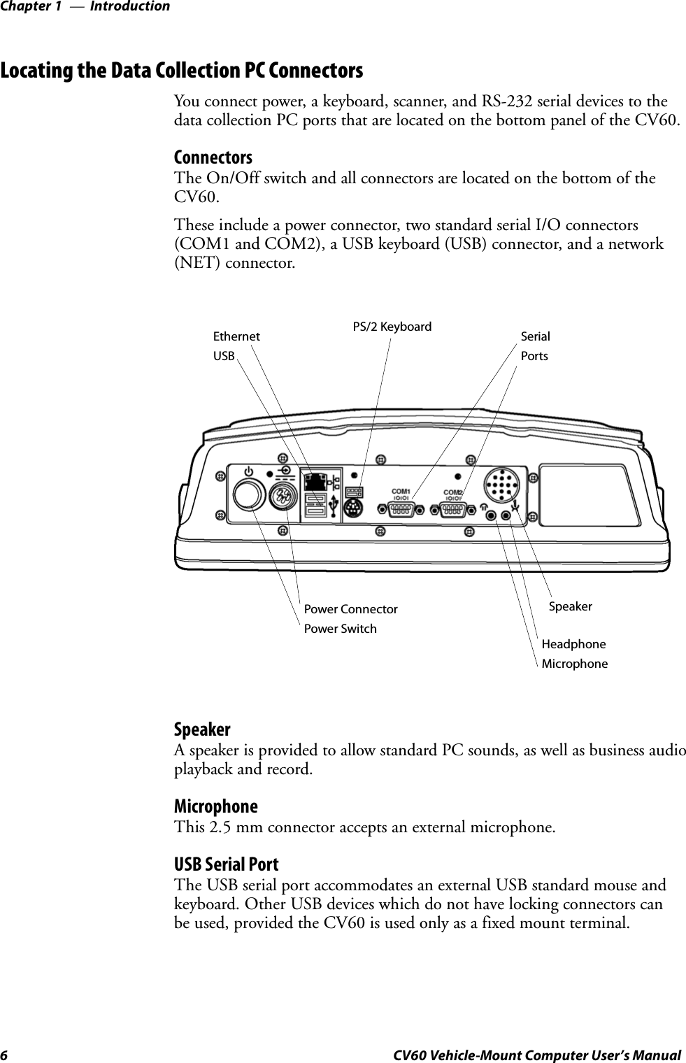
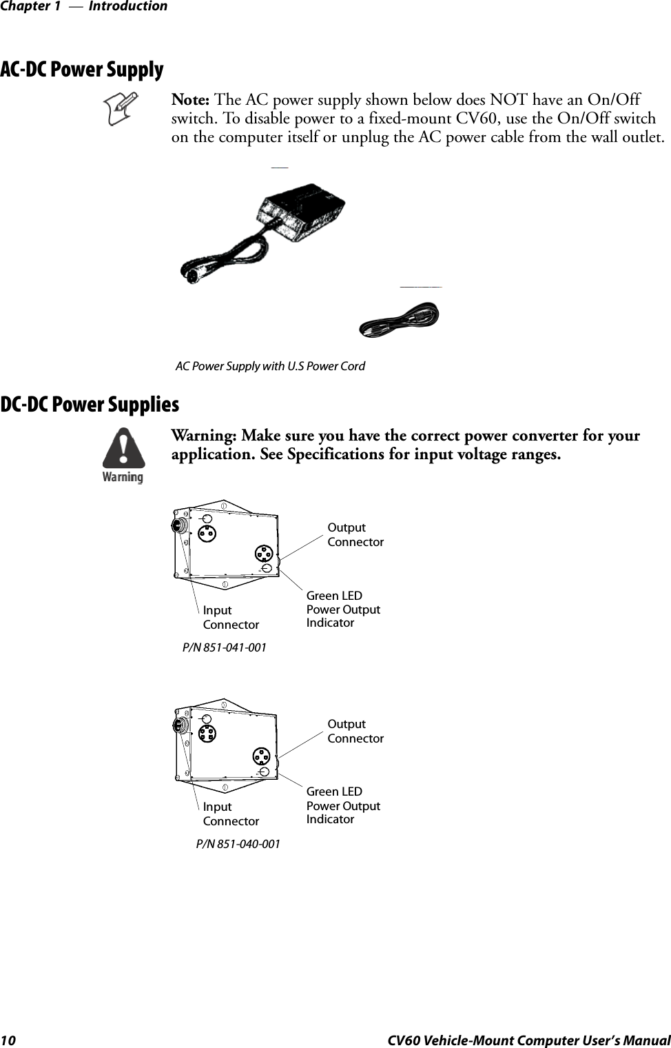
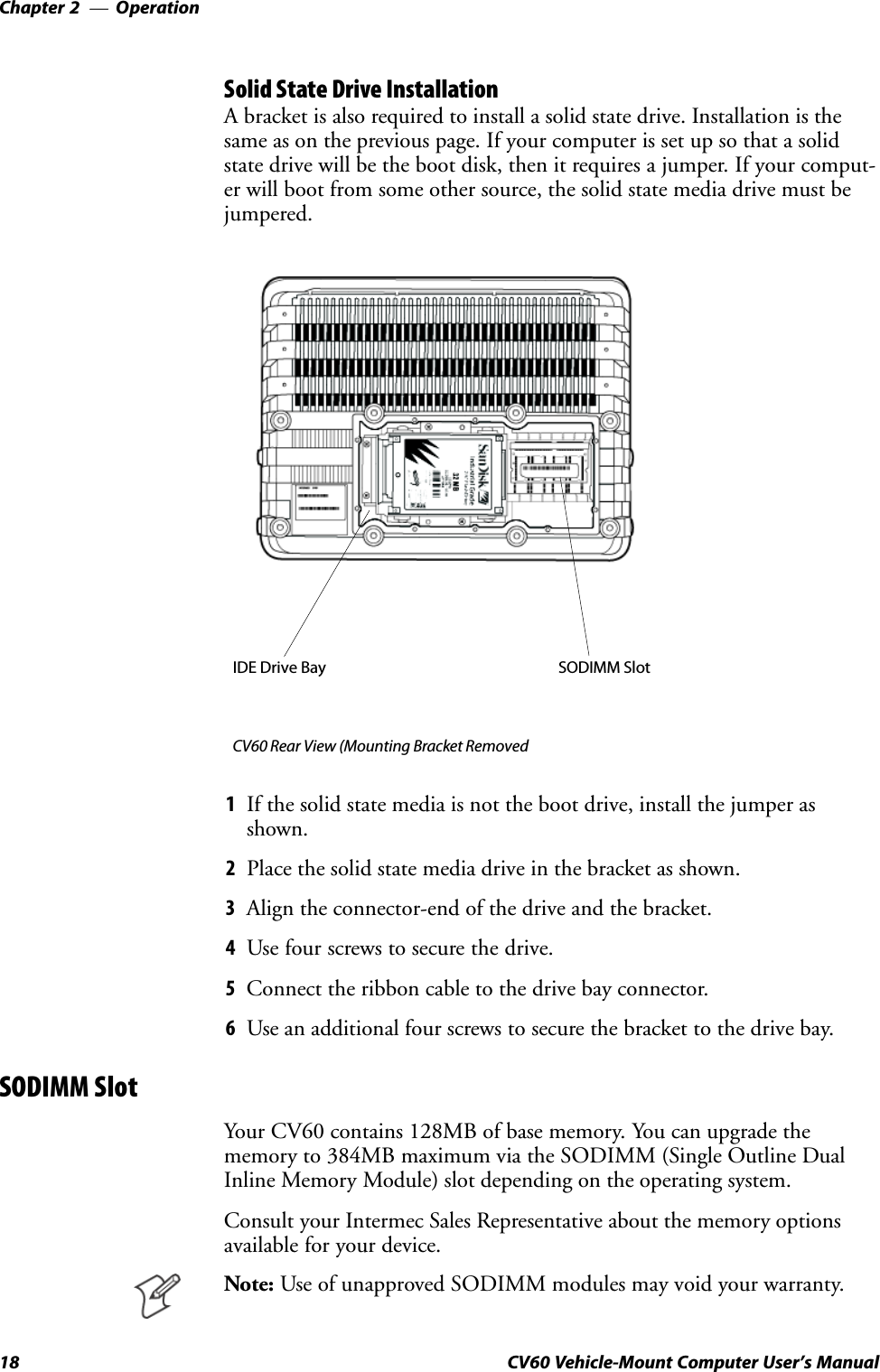
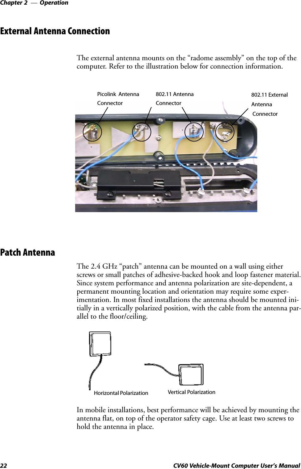

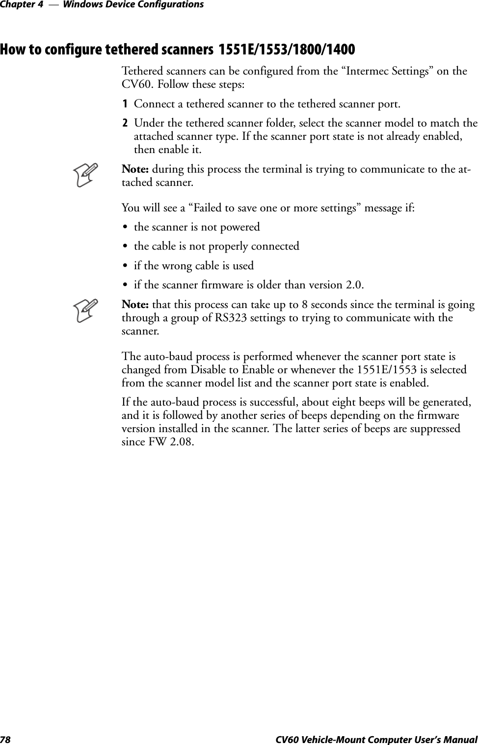
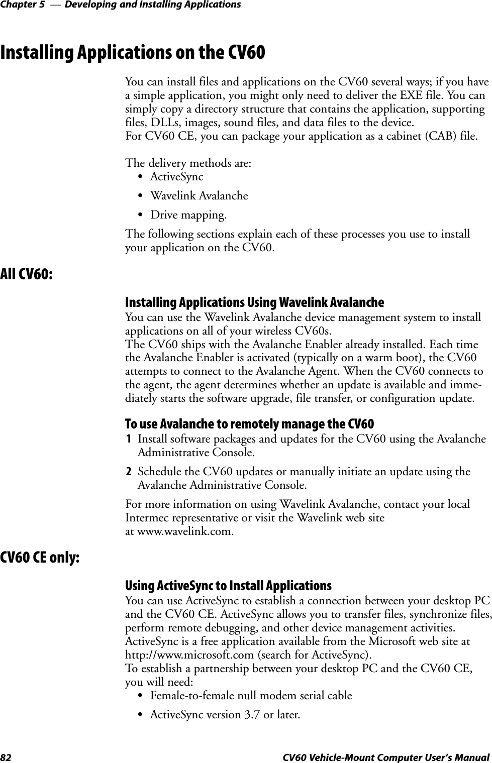
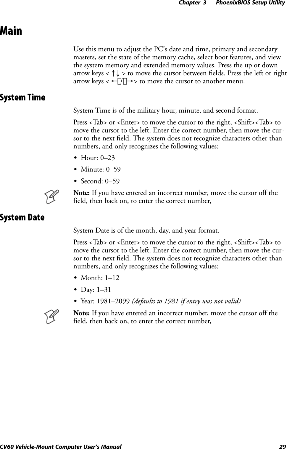
![27CV60 Vehicle-Mount Computer User's ManualPhoenixBIOS Setup Utility3 A PS/2Ćcompatible keyboard is required to configure the PhoenixBIOSSetup Utility (PSU). Turn off the CV60 Vehicle-Mount Computer beforeattaching the keyboard, if one is not attached already.Reboot the CV60. Be ready to press the [F2] keys when the followingprompt appears on the bottom, left side of the Intermec screen:Press F2 for System UtilitiesWhen you see this prompt, you have approximately eight seconds to pressthe [F2] key to enter the PSU, otherwise the computer proceeds to bootup.Note: Any changes made to the PSU are not effective until they are savedand the CV60 is rebooted. Select Exit > Exit Saving Changes to save thechanges.Press <Esc> to exit any window without changes.](https://usermanual.wiki/Intermec-Technologies/802MIAG-CV60/User-Guide-479504-Page-39.png)
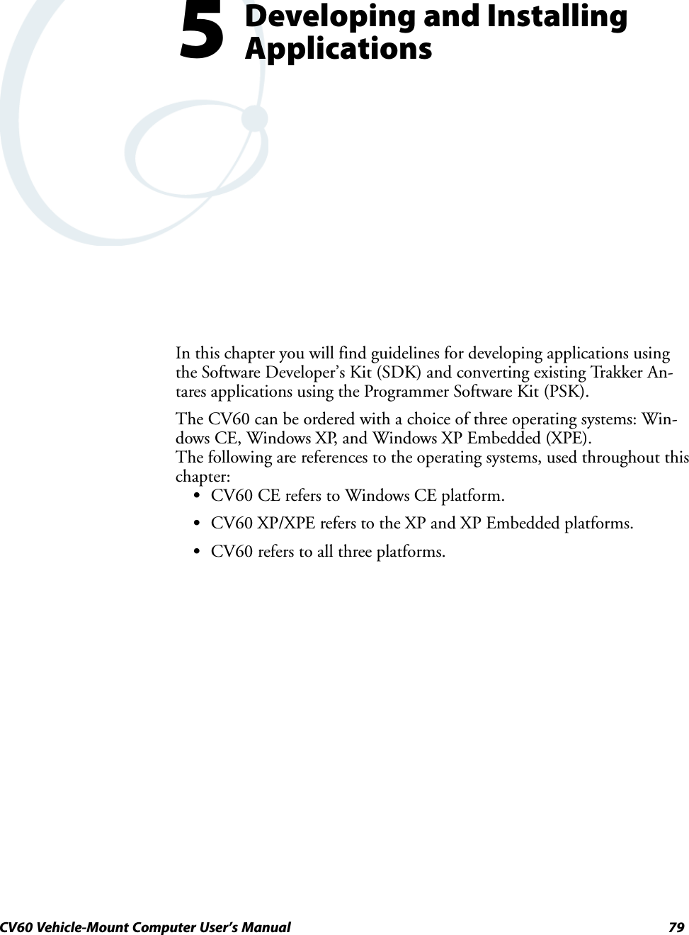
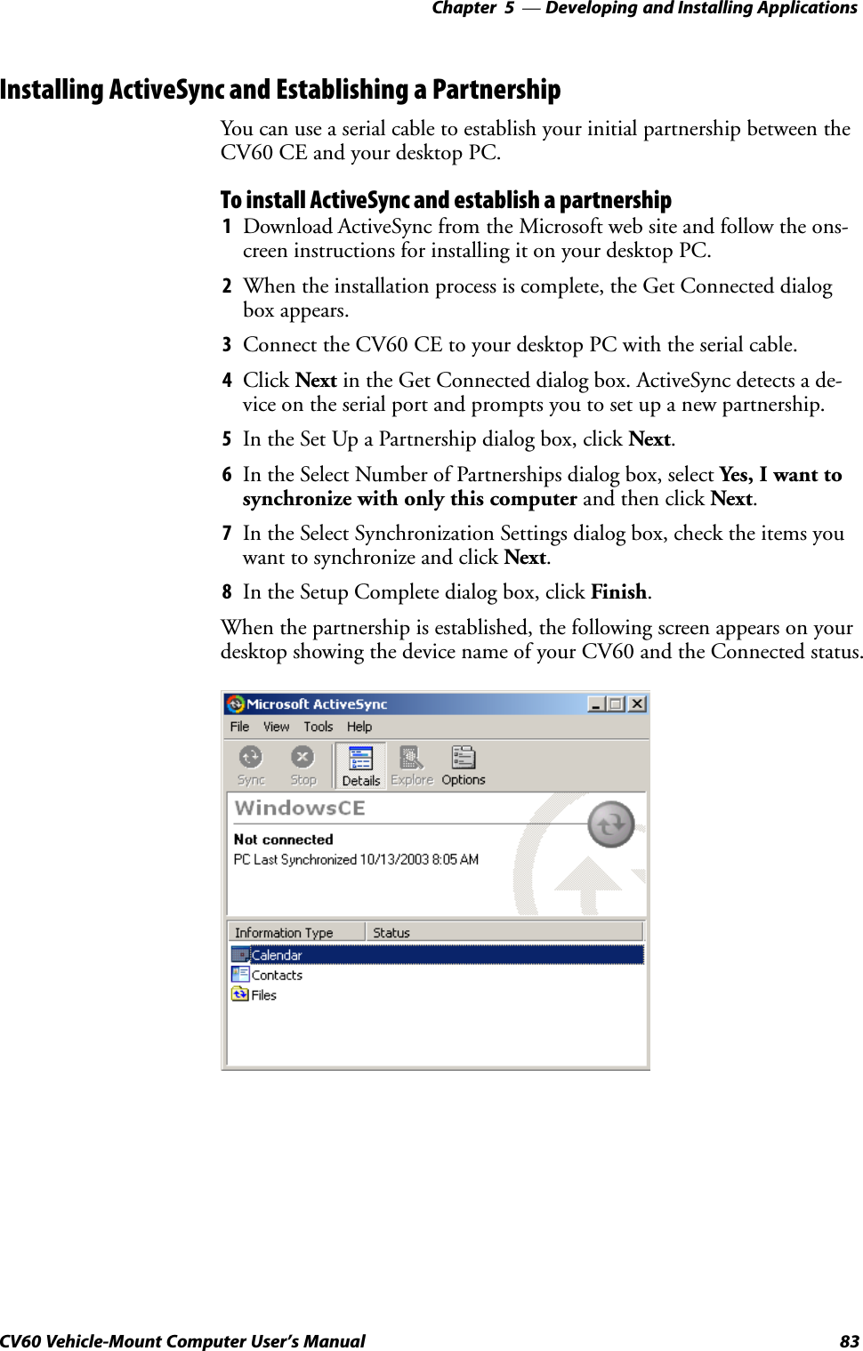
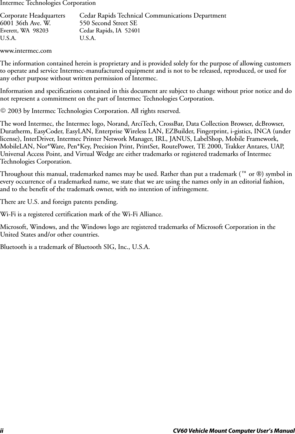
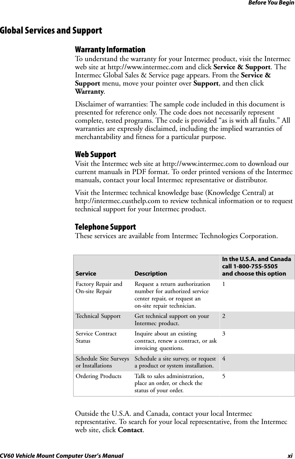
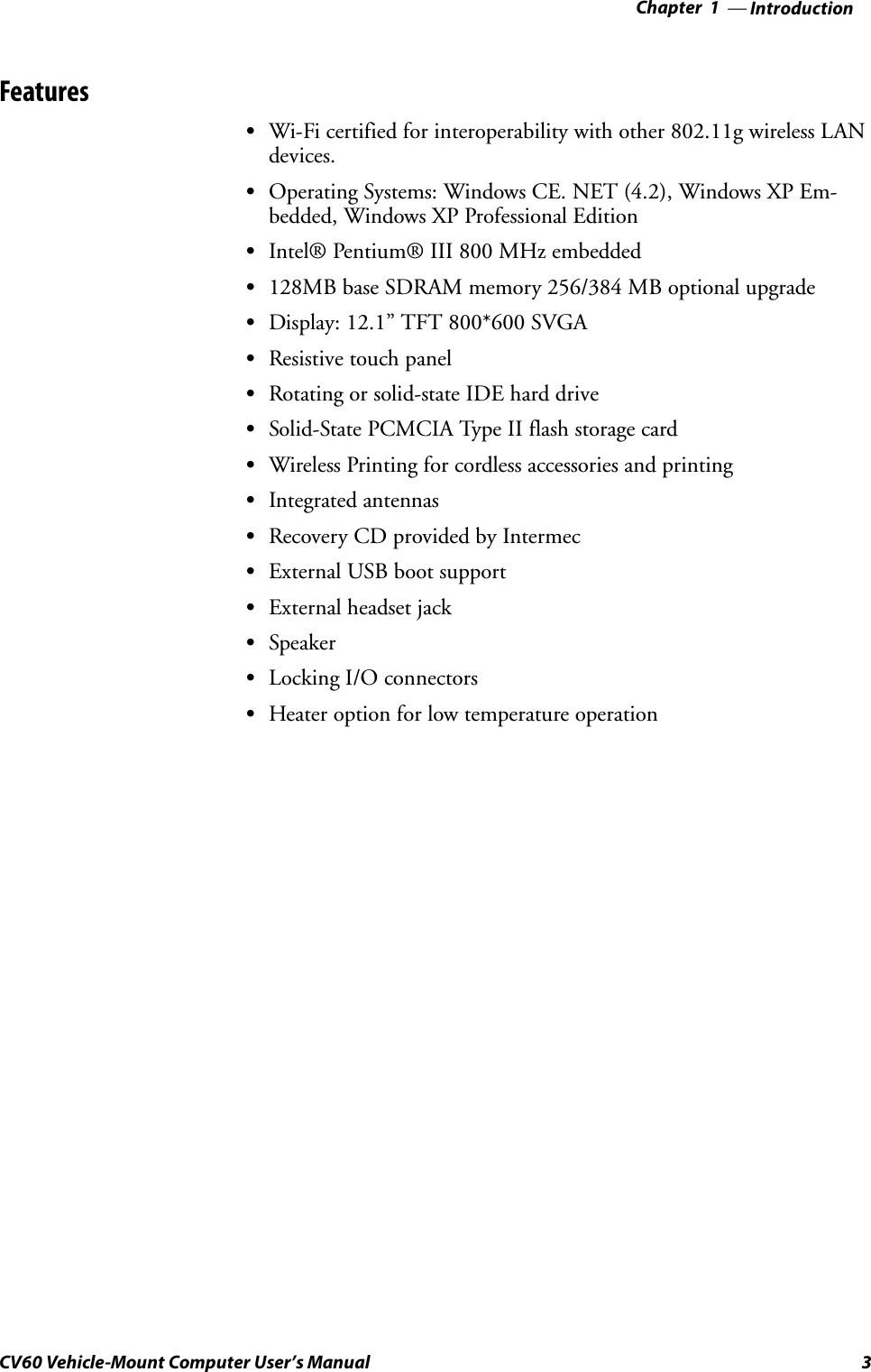
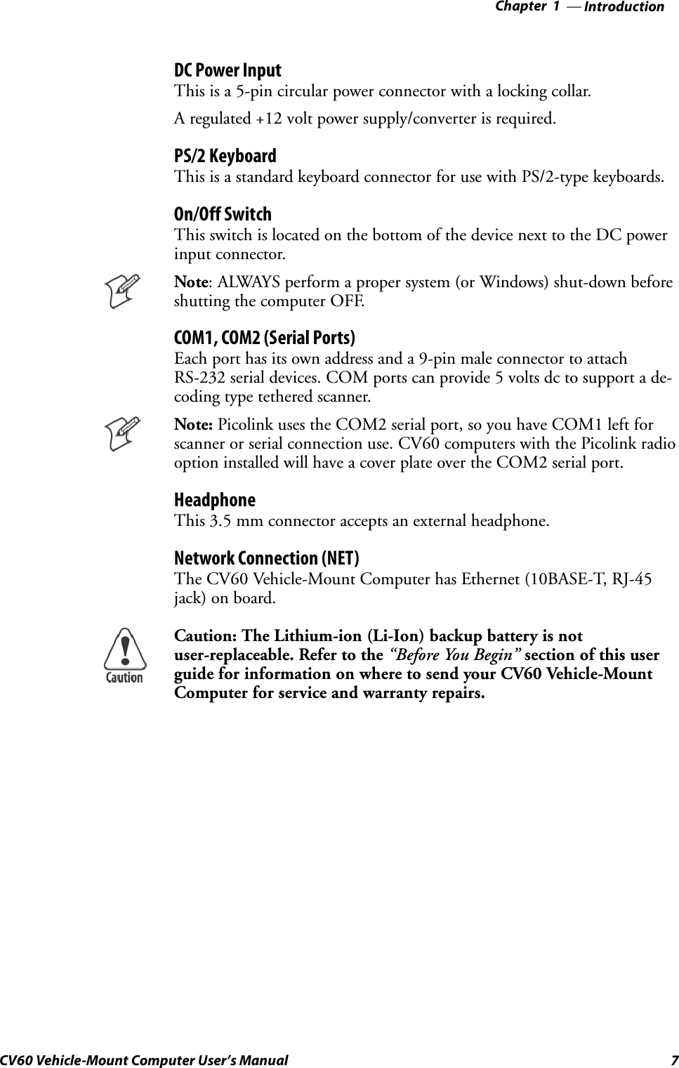
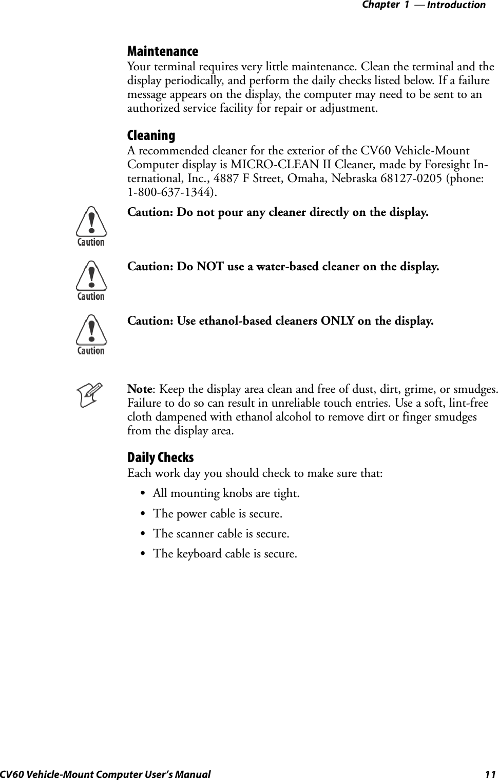
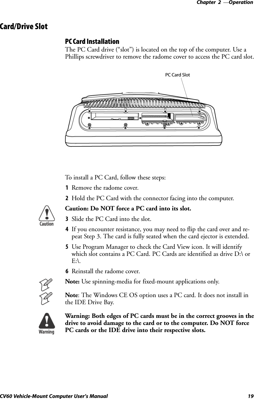
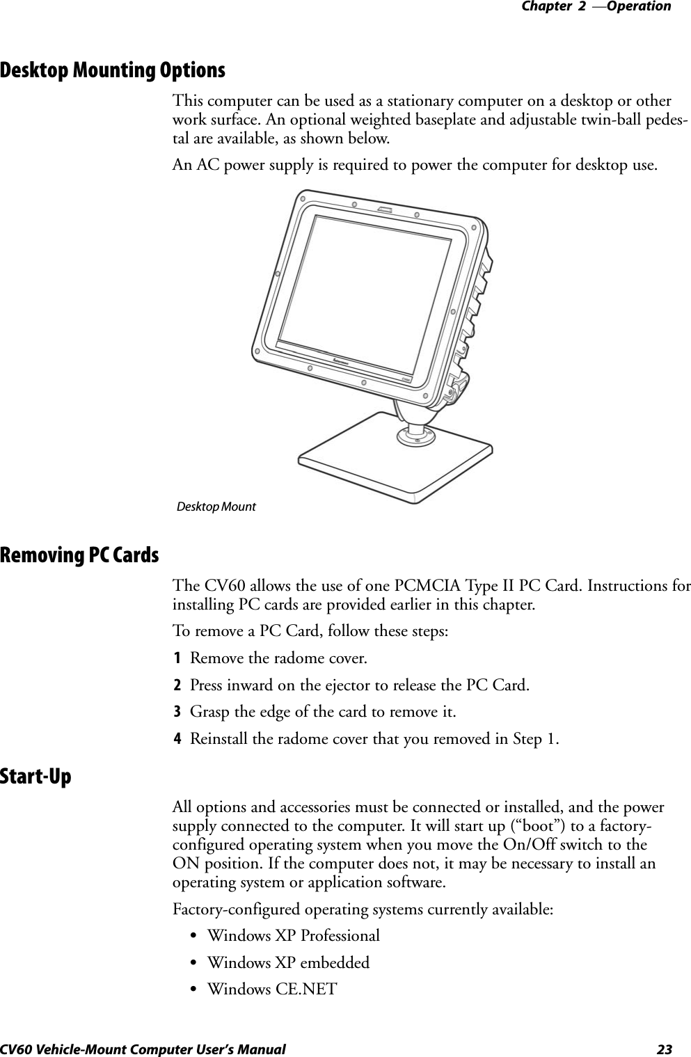
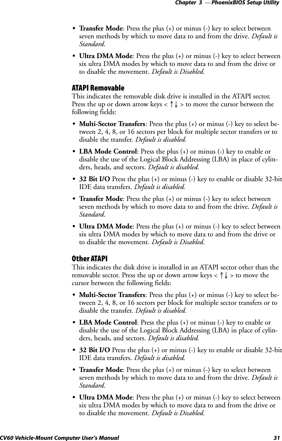
![PhoenixBIOS Setup UtilityChapter —328 CV60 Vehicle-Mount Computer User's ManualGeneral InformationThis page contains the same information as given in the General Help,available when you press [F1].Setup changes system behavior by modifying the BIOS configuration. SeĆlecting incorrect values may cause system boot failure, if so, then press [F9]to load setup default values to recover the system.SPress the up or down arrow keys < ↑↓ > to select fields in the currentmenu.SPress the <Page Up> or <Page Down> keys to move to the previous ornext page of scrollable menus.SPress the <Home> or <End> keys to move to the top or bottom item ofthe current menu.SWithin a field, press [F5} or < ć > (dash) to decrease the value, or press[F6} or < + > (plus symbol) to increase the value.SPress the left or right arrow keys < ← / → > to move between menus.SPress <Enter> to display more options for items marked with ".SPress [F9] to load factoryĆinstalled Setup Default values.SPress [F10] to save the current settings and exit the PSU.SPress either <Esc> or <Alt> [X] to exit the Setup or to return to the preĆvious menu.SPress [F1] or <Alt> [H] to display General Help information. Press [F1]or <Enter> to close the General Help screen.](https://usermanual.wiki/Intermec-Technologies/802MIAG-CV60/User-Guide-479504-Page-40.png)
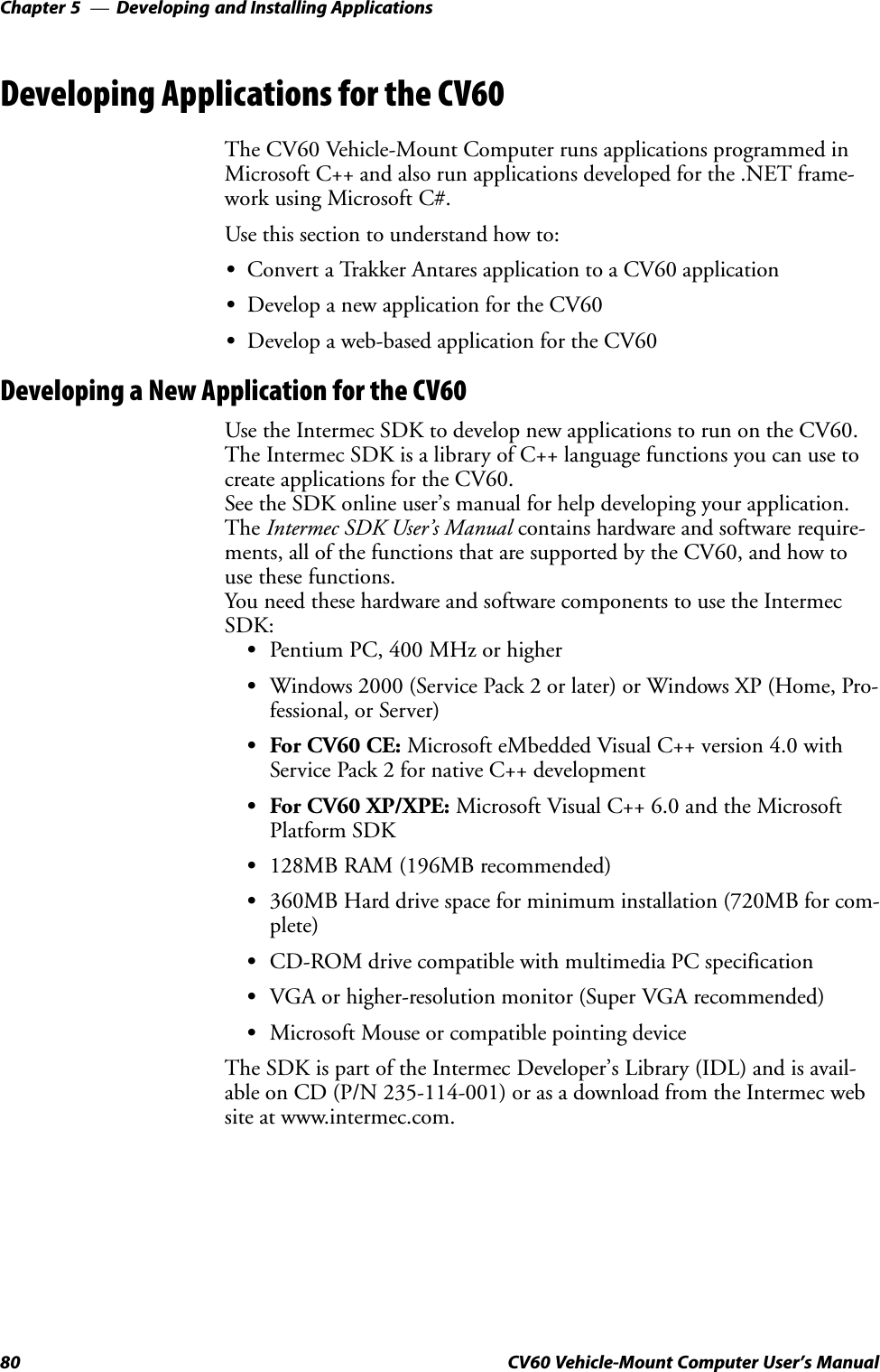
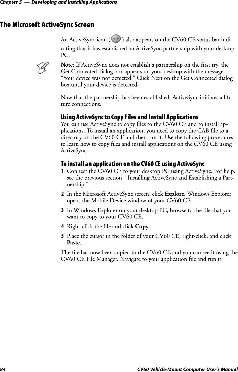
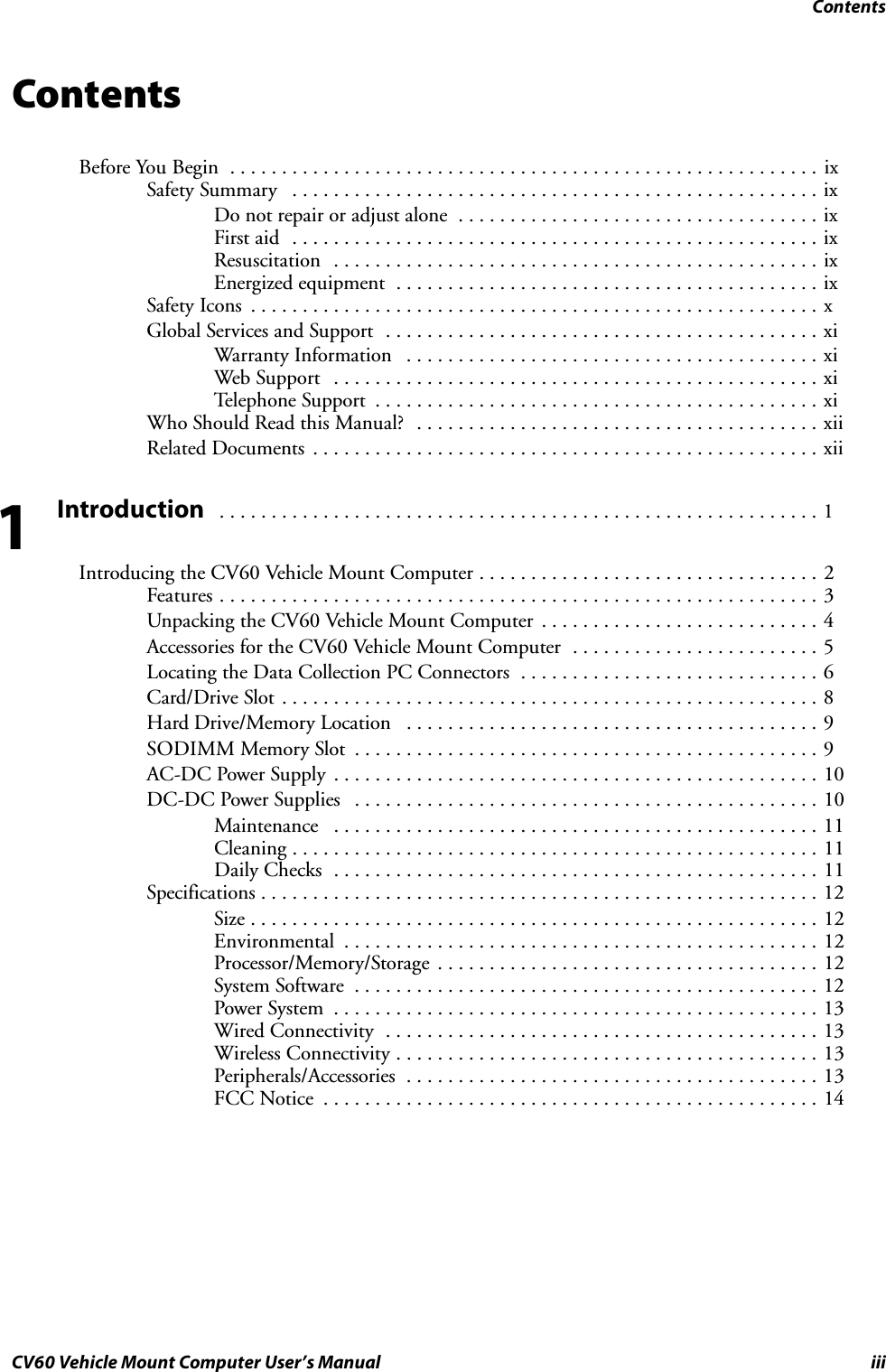
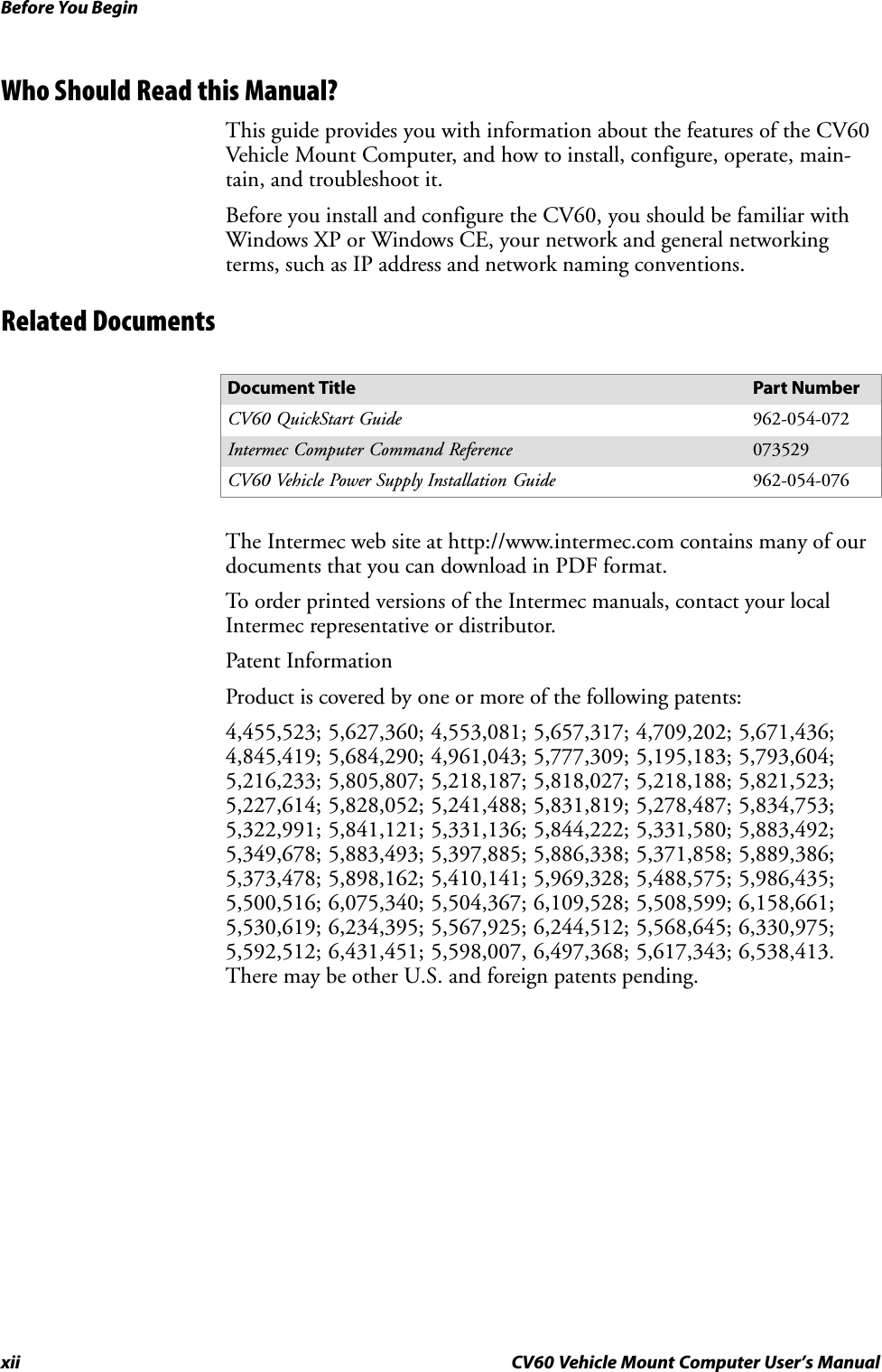
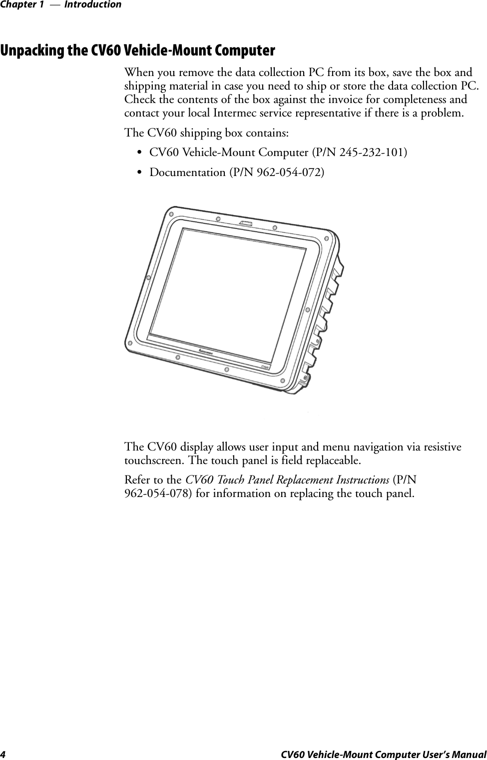
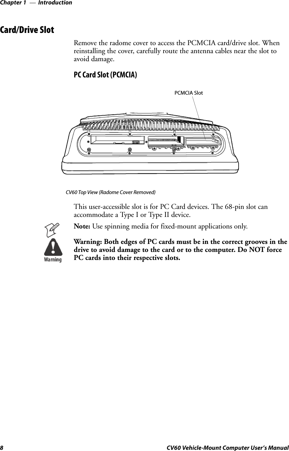
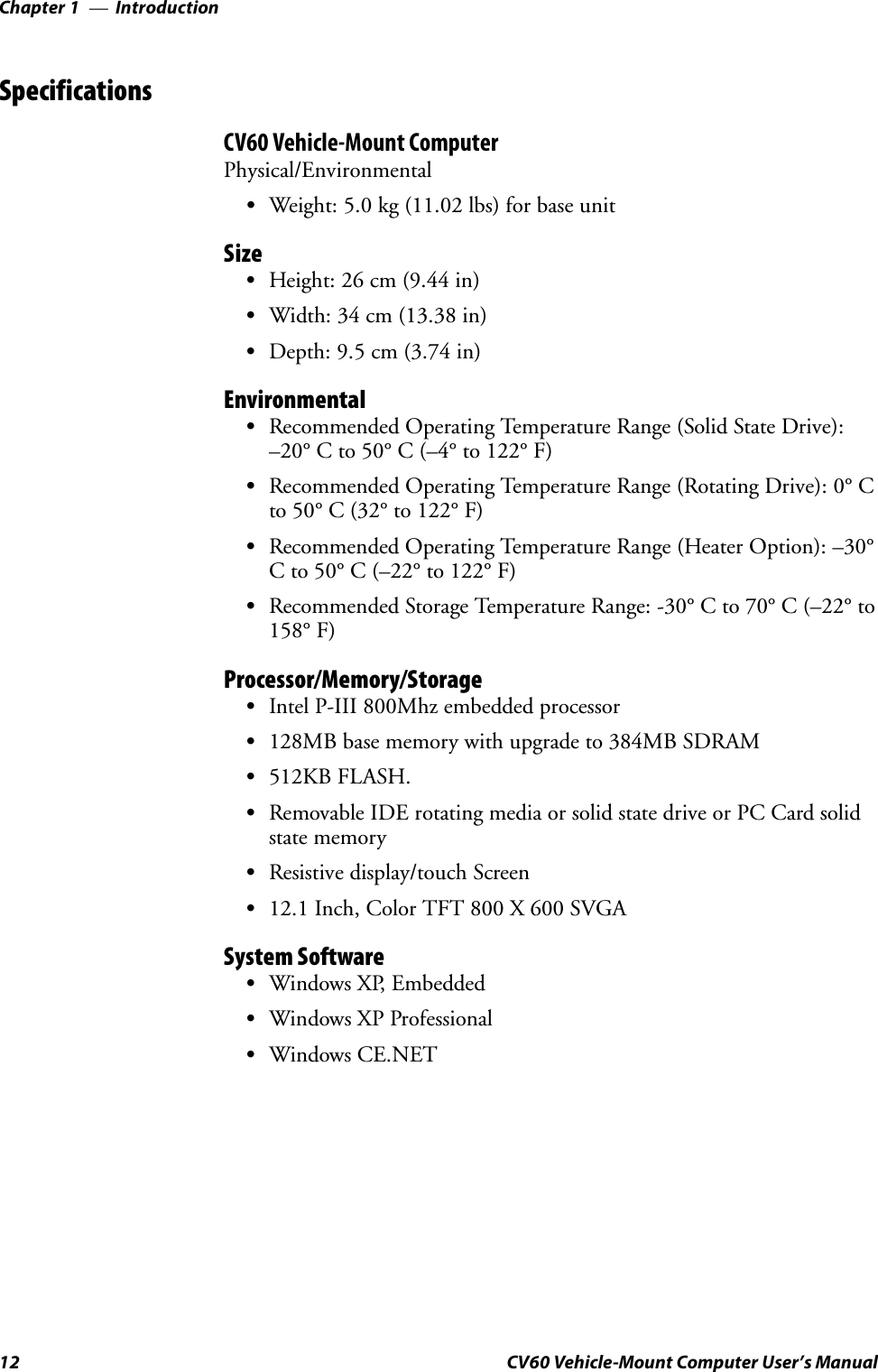
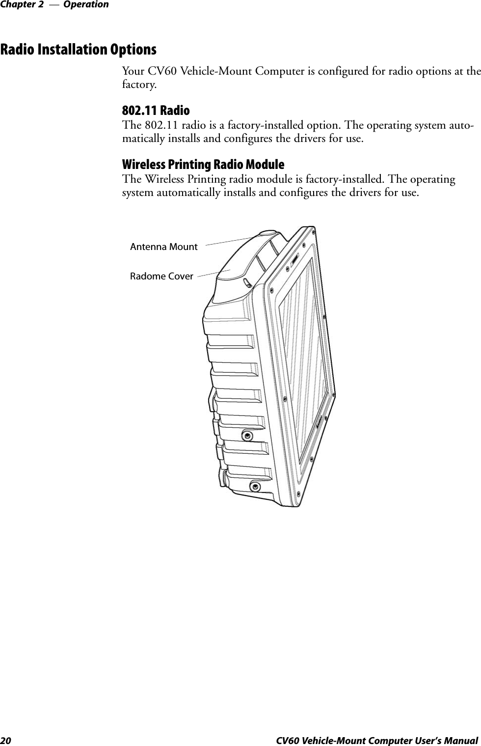
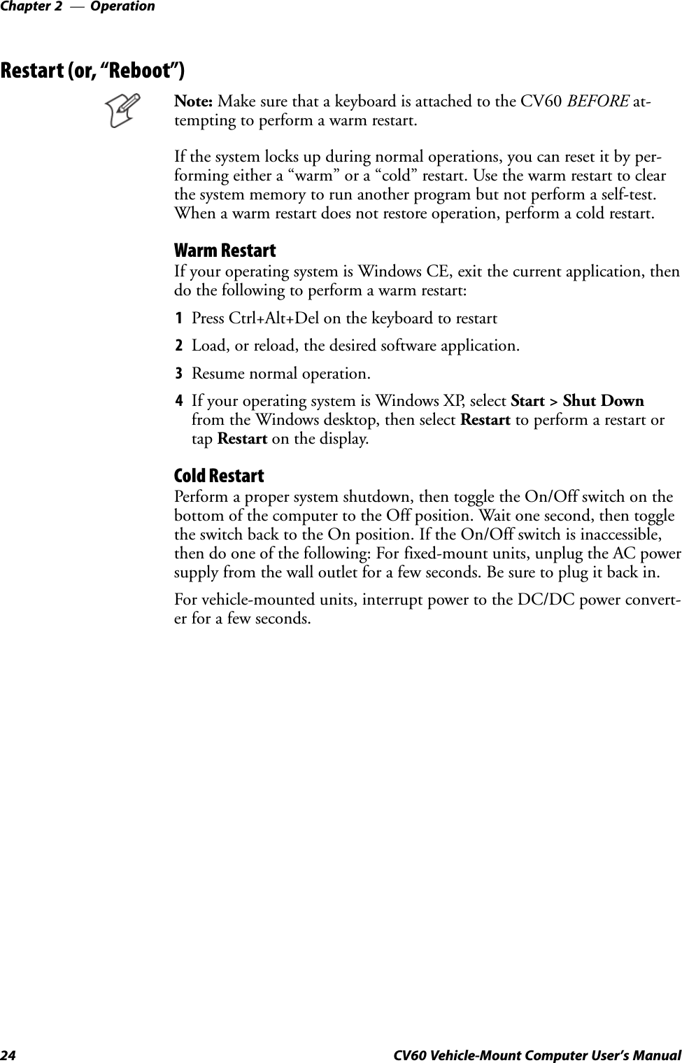
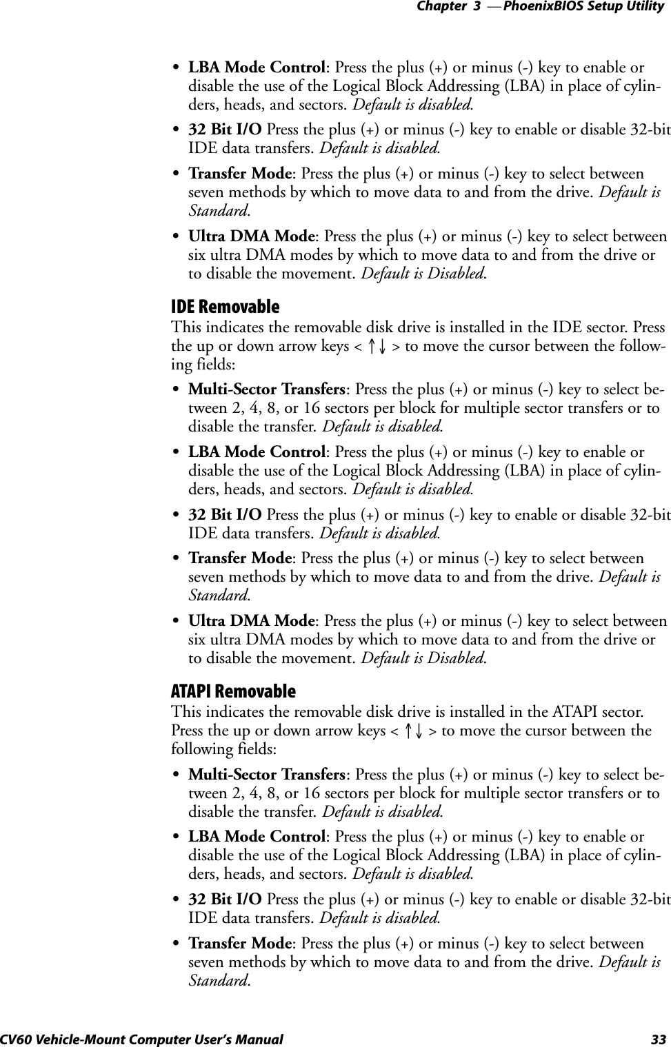
![PhoenixBIOS Setup UtilityChapter —330 CV60 Vehicle-Mount Computer User's ManualPrimary MasterPress [Enter] to access the Primary Master menu. Press [Esc] to return tothe Main menu.At the Type field, press the plus (+) or minus (-) key to change the value toone of the following. The value selected dictates what configurable inforĆmation is presented. Default is None.AutoSelect this to automatically set the hardĆdisk drive installed. Press the up ordown arrow keys < ↑↓ > to move the cursor to the following field:S32 Bit I/O: Press the plus (+) or minus (-) key to enable or disable32Ćbit IDE data transfers. Default is disabled.NoneSelect this if there is no hardĆdisk drive.CDĆROMThis indicates that a CDĆROM drive is the drive installed. Press the up ordown arrow keys < ↑↓ > to move the cursor between the following fields:SMultiĆSector Transfers: Press the plus (+) or minus (-) key to select beĆtween 2, 4, 8, or 16 sectors per block for multiple sector transfers or todisable the transfer. Default is disabled.SLBA Mode Control: Press the plus (+) or minus (-) key to enable ordisable the use of the Logical Block Addressing (LBA) in place of cylinĆders, heads, and sectors. Default is disabled.S32 Bit I/O Press the plus (+) or minus (-) key to enable or disable 32ĆbitIDE data transfers. Default is disabled.STransfer Mode: Press the plus (+) or minus (-) key to select betweenseven methods by which to move data to and from the drive. Default isStandard.SUltra DMA Mode: Press the plus (+) or minus (-) key to select betweensix ultra DMA modes by which to move data to and from the drive orto disable the movement. Default is Disabled.IDE RemovableThis indicates the removable disk drive is installed in the IDE sector. Pressthe up or down arrow keys < ↑↓ > to move the cursor between the followĆing fields:SMultiĆSector Transfers: Press the plus (+) or minus (-) key to select beĆtween 2, 4, 8, or 16 sectors per block for multiple sector transfers or todisable the transfer. Default is disabled.SLBA Mode Control: Press the plus (+) or minus (-) key to enable ordisable the use of the Logical Block Addressing (LBA) in place of cylinĆders, heads, and sectors. Default is disabled.S32 Bit I/O Press the plus (+) or minus (-) key to enable or disable 32ĆbitIDE data transfers. Default is disabled.](https://usermanual.wiki/Intermec-Technologies/802MIAG-CV60/User-Guide-479504-Page-42.png)
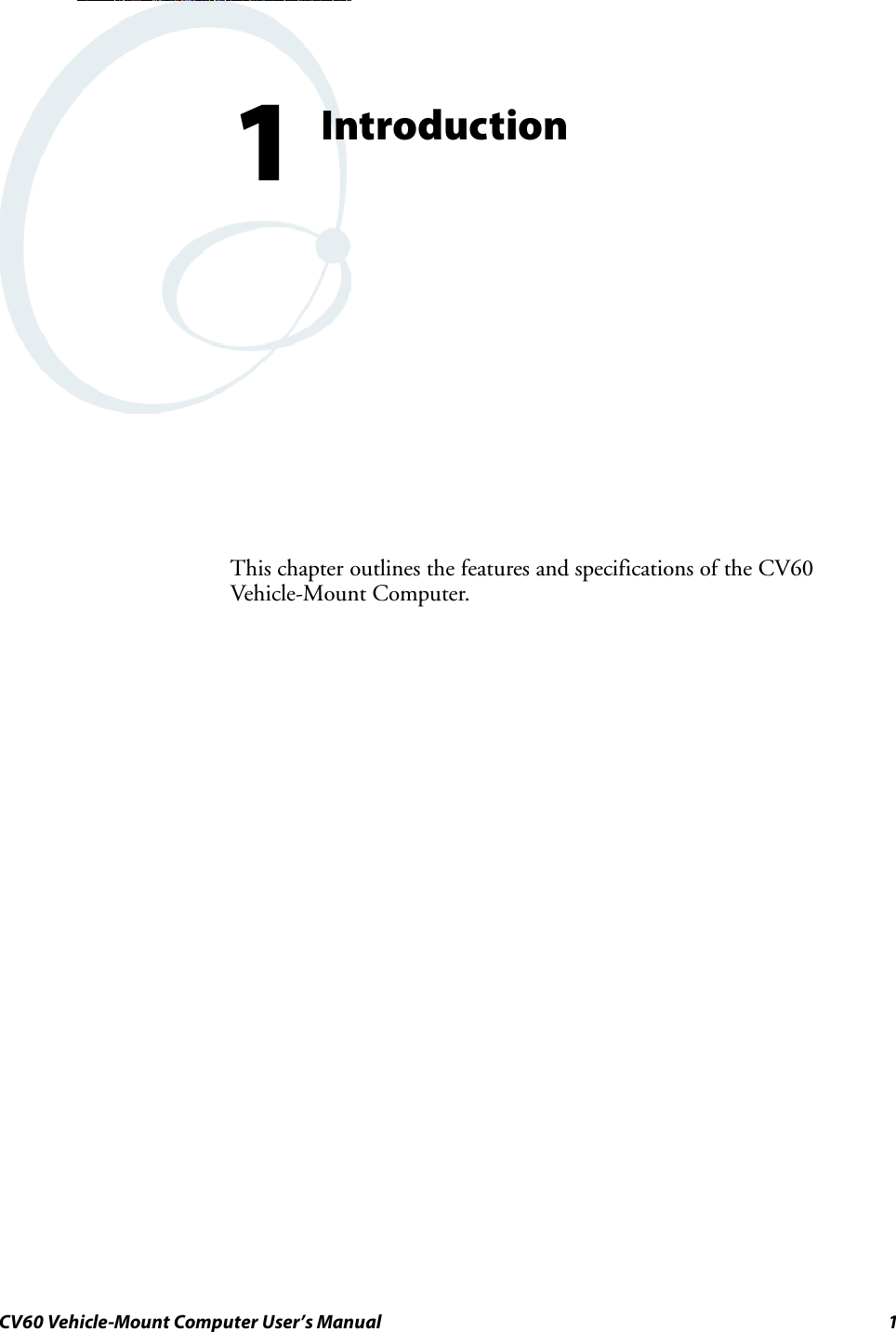
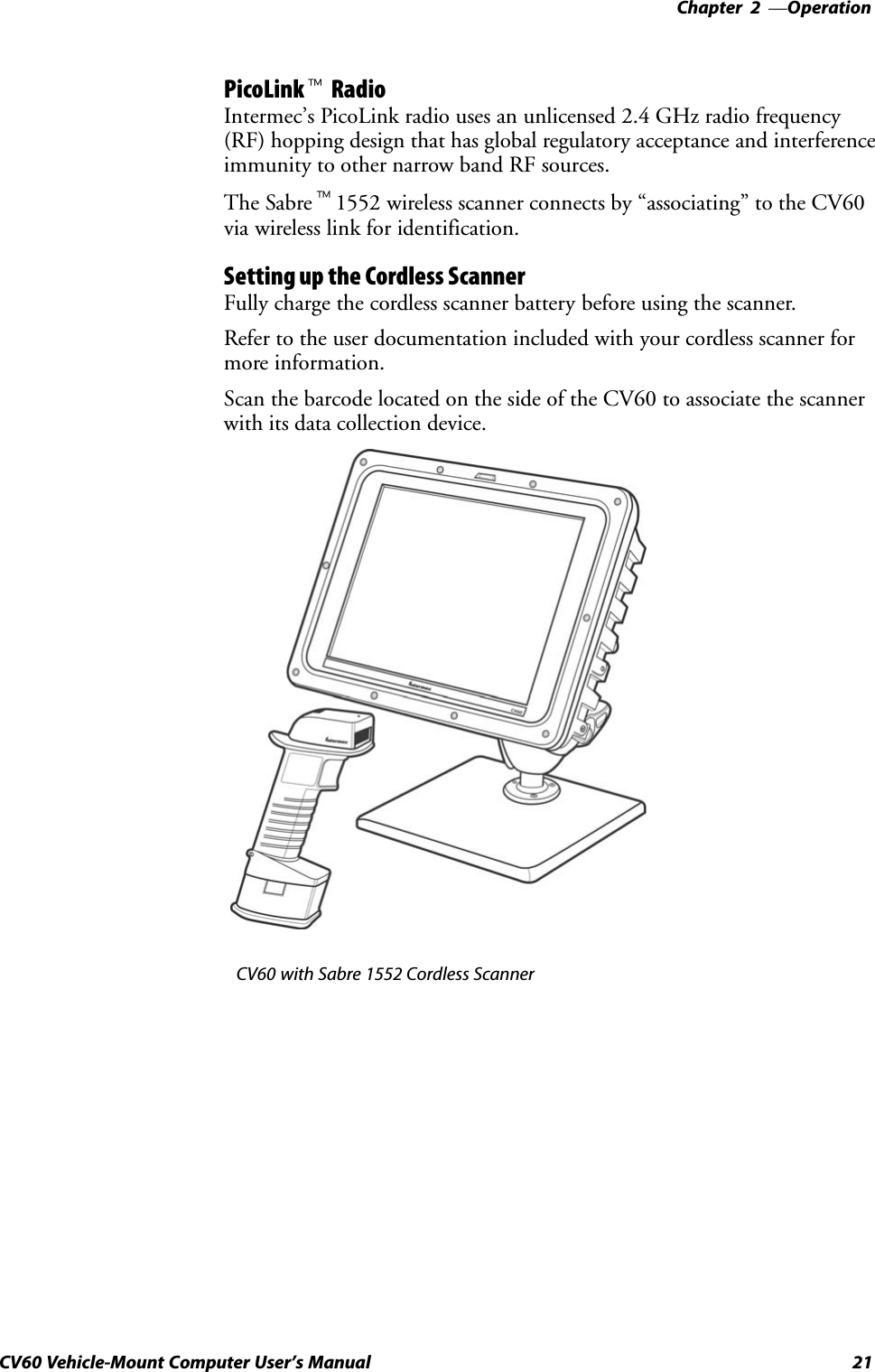
![PhoenixBIOS Setup UtilityChapter —332 CV60 Vehicle-Mount Computer User's ManualUserEnter the parameters of the hardĆdisk drive installed at this connection.Press the up or down arrow keys < ↑↓ > to move the cursor between thefollowing fields:SCylinders: Enter the number of cylinders involved in this capacity,range is 0 through 65535. Default is 0.SHeads: Enter the number of heads involved in this capacity, range is 1through 16. Default is 1.SSectors: Enter the number of sectors involved in this capacity, range is 0through 63. Default is 0.SMultiĆSector Transfers: Press the plus (+) or minus (-) key to select beĆtween 2, 4, 8, or 16 sectors per block for multiple sector transfers or todisable the transfer. Default is disabled.SLBA Mode Control: Press the plus (+) or minus (-) key to enable ordisable the use of the Logical Block Addressing (LBA) in place of cylinĆders, heads, and sectors. Default is disabled.S32 Bit I/O Press the plus (+) or minus (-) key to enable or disable 32ĆbitIDE data transfers. Default is disabled.STransfer Mode: Press the plus (+) or minus (-) key to select betweenseven methods by which to move data to and from the drive. Default isStandard.SUltra DMA Mode: Press the plus (+) or minus (-) key to select betweensix ultra DMA modes by which to move data to and from the drive orto disable the movement. Default is Disabled.Secondary MasterPress [Enter] to access the Secondary Master menu. Press [Esc] to returnto the Main menu.At the Type field, press the plus (+) or minus (-) key to change the value toone of the following. The value selected dictates what configurable inforĆmation is presented. Default is SanDisk SDP3B-85.AutoSelect this to automatically set the hardĆdisk drive installed. Press the up ordown arrow keys < ↑↓ > to move the cursor to the following field:S32 Bit I/O: Press the plus (+) or minus (-) key to enable or disable32Ćbit IDE data transfers. Default is disabled.NoneSelect this if there is no hardĆdisk drive.CDĆROMThis indicates that a CDĆROM drive is the drive installed. Press the up ordown arrow keys < ↑↓ > to move the cursor between the following fields:SMultiĆSector Transfers: Press the plus (+) or minus (-) key to select beĆtween 2, 4, 8, or 16 sectors per block for multiple sector transfers or todisable the transfer. Default is disabled.](https://usermanual.wiki/Intermec-Technologies/802MIAG-CV60/User-Guide-479504-Page-44.png)
![PhoenixBIOS Setup Utility—Chapter 335CV60 Vehicle-Mount Computer User's ManualMemory CachePress [Enter] to access the Memory Cache menu and set the state of thememory cache. Press [Esc] to return to the Main menu.Memory CachePress the plus (+) or minus (-) key to enable or disable the memory cache.Default is enabled.Cache System/Video BIOS AreasPress the plus (+) or minus (-) key to select either Write Protect" or unĆcached" to control the caching of the system BIOS area. Default is WriteProtectCache Base 0ć512k, 512kć640k, Extended Memory AreaPress the plus (+) or minus (-) key to select Write Back," uncached,"Write Through," or Write Protect" to control the caching of the 512k or512k through 640k base memory or extended memory area. Default isWrite Back.Cache A000ćAFFF, B000ćBFFFPress the plus (+) or minus (-) key to select Disabled," USWC Caching,"Write Through," Write Protect," or Write Back" to control the apĆpropriate cache range. Default is Disabled.Cache C800ćCBFF through EC00ćEFFFPress the plus (+) or minus (-) key to select Disabled," Write Through,"Write Protect," or Write Back" to control the appropriate cache range.Default is Disabled.Boot FeaturesPress [Enter] to access the Boot Features menu and configure the floppycheck, the summary screen, the bootĆtime diagnostic screen, or the QuickĆBoot mode. Press [Esc] to return to the Main menu.Summary ScreenPress the plus (+) or minus (-) key to dictate whether to display systemconfiguration information on boot. Default is enabled.BootĆTime Diagnostic ScreenPress the plus (+) or minus (-) key to state whether to display the diagnosĆtic screen during the boot up process. Default is disabled.QuickBoot ModePress the plus (+) or minus (-) key to dictate whether the system can skipcertain tests during the boot process, thus shortening the time required toperform the boot. Default is enabled.](https://usermanual.wiki/Intermec-Technologies/802MIAG-CV60/User-Guide-479504-Page-47.png)
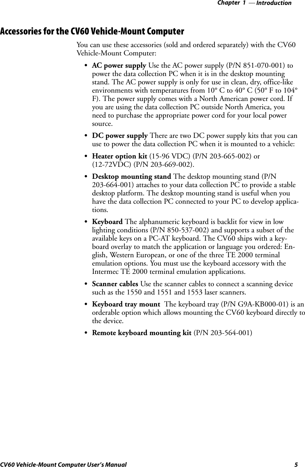
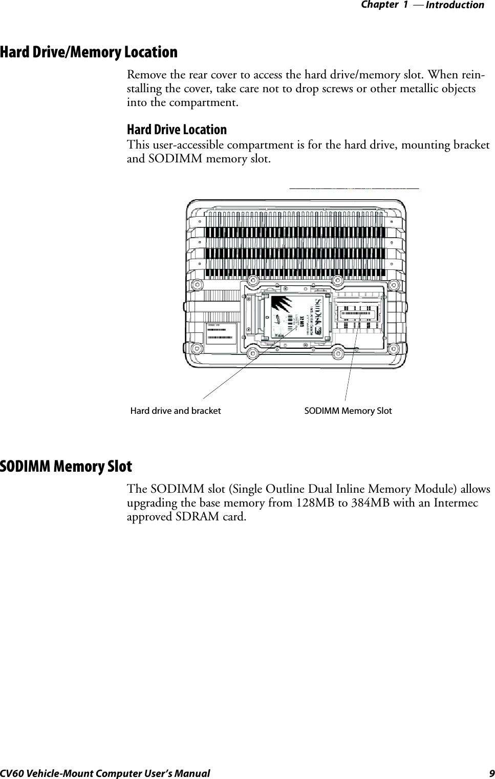
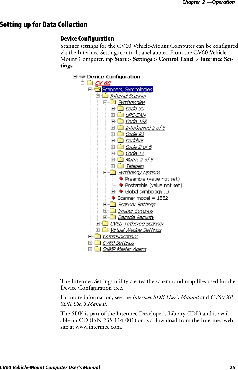
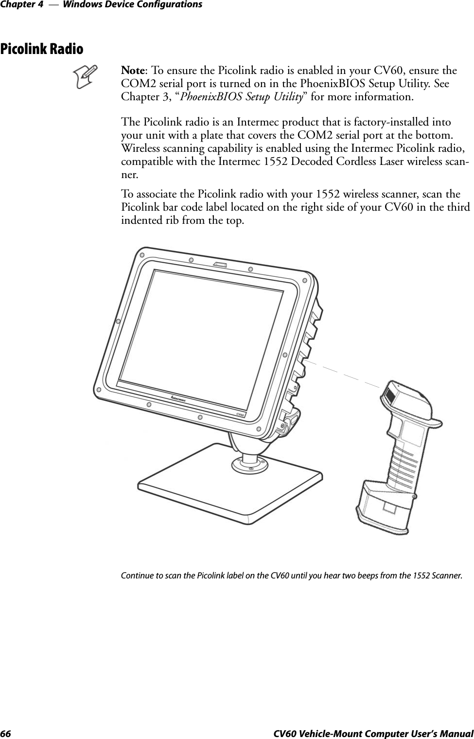
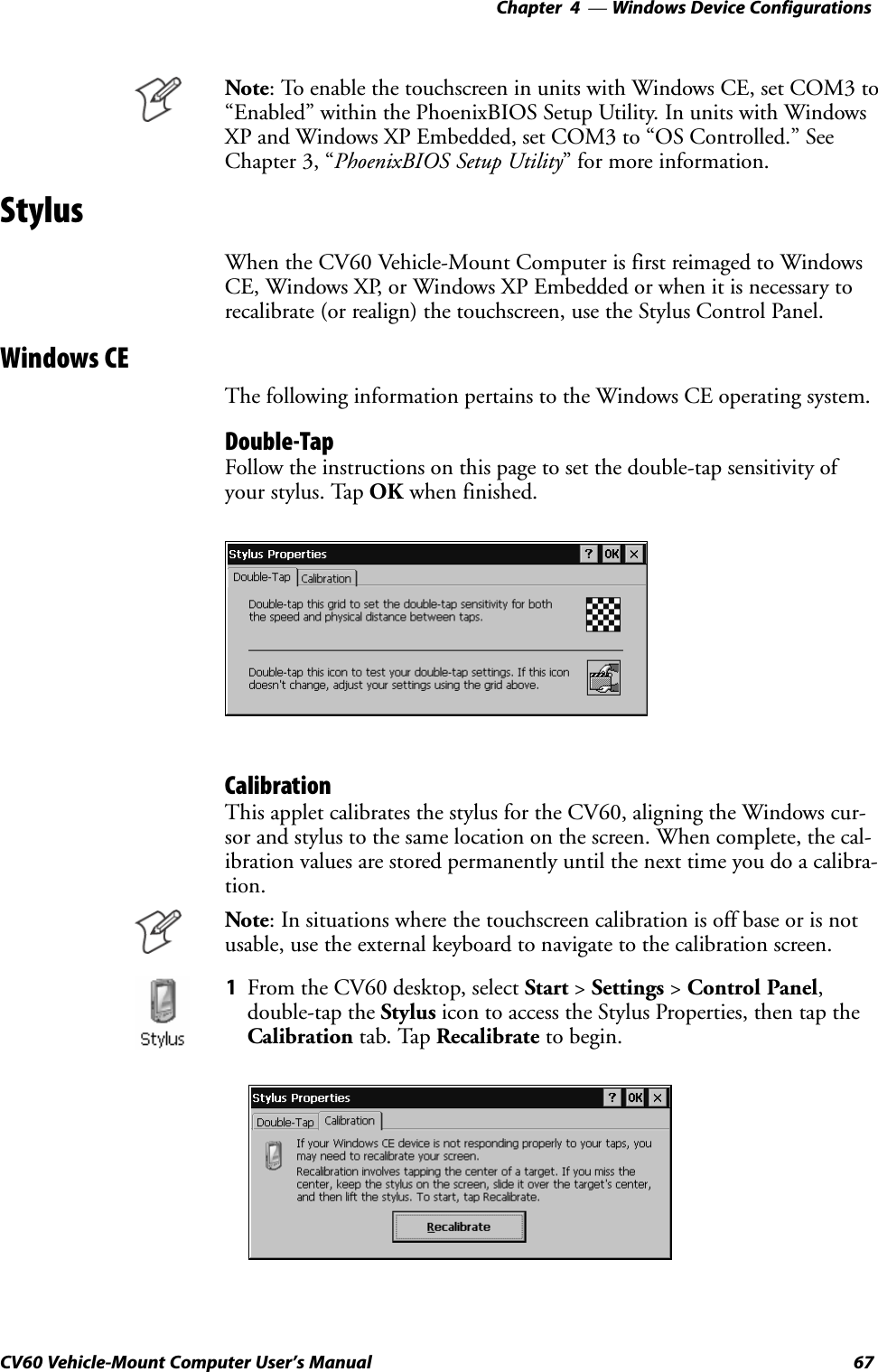
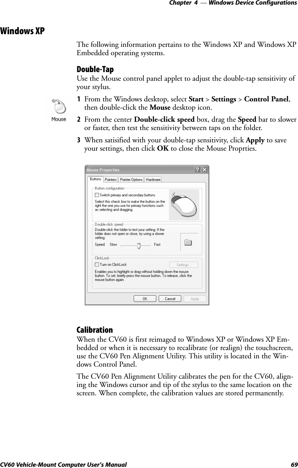
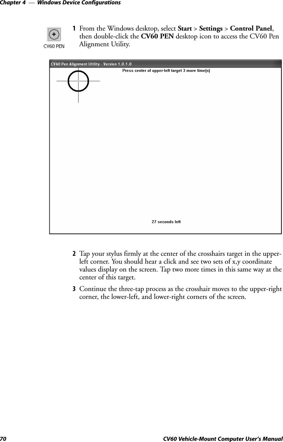
![PhoenixBIOS Setup UtilityChapter —336 CV60 Vehicle-Mount Computer User's ManualAdvancedThis configures advanced features within your CV60. Press the up ordown arrow keys < ↑↓ > to move the cursor to the following fields. Pressthe left or right arrow keys < ←/→ > to move the cursor to anothermenu.Caution: If you set items in this menu to incorrect values, you couldcause your system to malfunction. Advanced Chipset ControlPress [Enter] to access the Advanced Chipset Control menu and configurethe video boot type, the enable memory gap, or the frequency ratio. Press[Esc] to return to the Advanced menu.Video Boot TypePress the plus (+) or minus (-) key to select either 512 KB or 1 MB of sysĆtem memory to allocate to the onboard video controller. Default is 1 MB.Enable Memory GapPress the plus (+) or minus (-) key to select either Disabled" or ExĆtended." If Extended," this turns off the system RAM to free space for usewith an option card. Default is disabled.Frequency RatioPress the plus (+) or minus (-) key to select from fourteen different internalfrequency multiplier values of the CPU. Default is 4x.I/O Device ConfigurationPress [Enter] to access the Advanced Chipset Control menu and configureperipheral devices, such as serial ports, panel heater circuit and power, orthe Picolink radio. Press [Esc] to return to the Advanced menu.Serial PortsPress the plus (+) or minus (-) key to select Disabled," Enabled," Auto,"or OS Controlled" to configure serial ports A through D.If Enabled" is selected, press the plus (+) or minus (-) key to set the baseI/O address and the interrupt for the enabled serial port. Default is OSControlled.Note: To enable the touchscreen, select Enabled" for Windows CE sysĆtems and OS Controlled" for Windows XP systems.Panel HeaterPress the plus (+) or minus (-) key to enable or disable the panel heater cirĆcuit and power. Default is disabled.PicolinkPress the plus (+) or minus (-) key to enable or disable support for the PiĆcolink radio. Default is disabled.](https://usermanual.wiki/Intermec-Technologies/802MIAG-CV60/User-Guide-479504-Page-48.png)
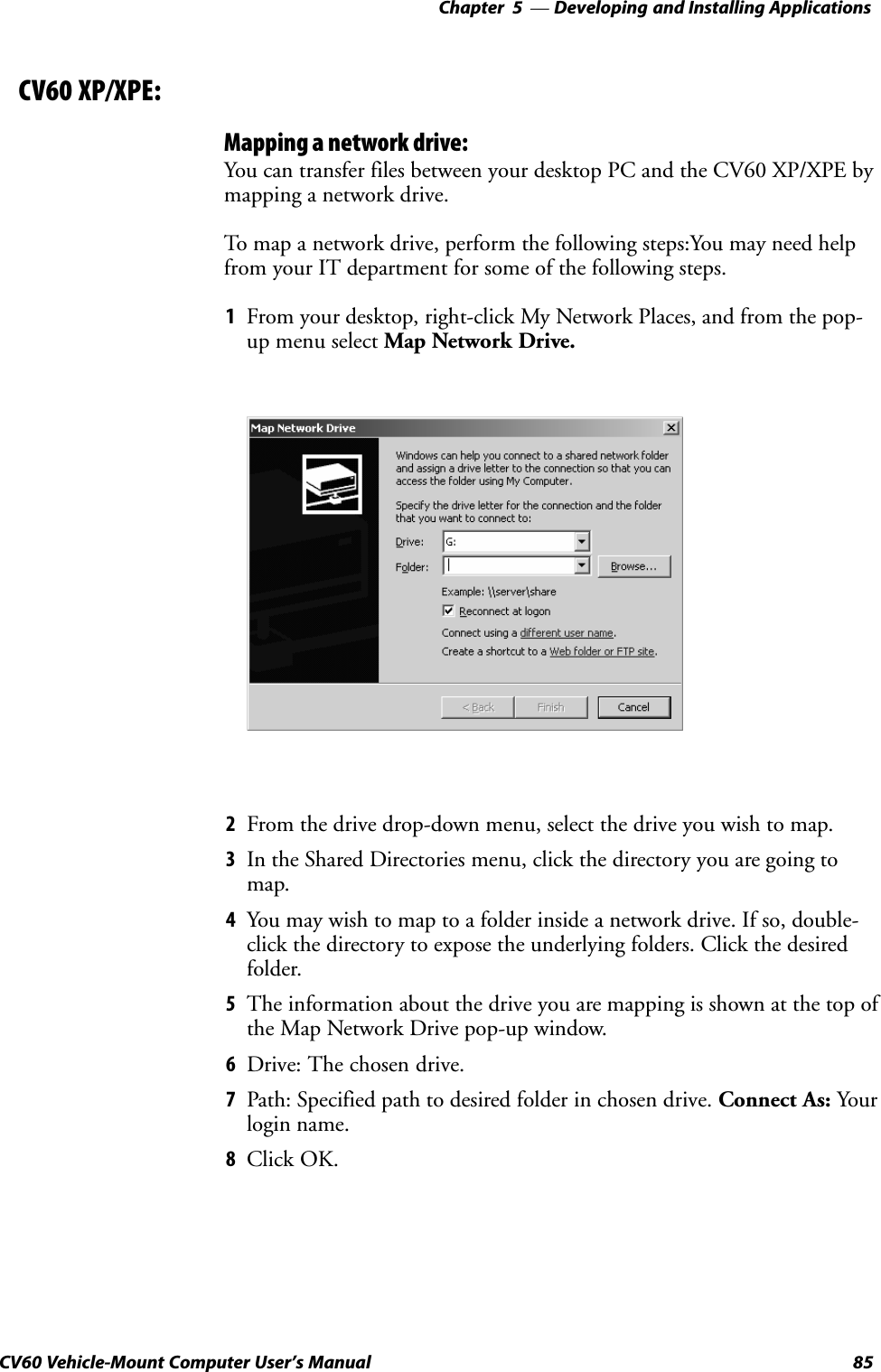
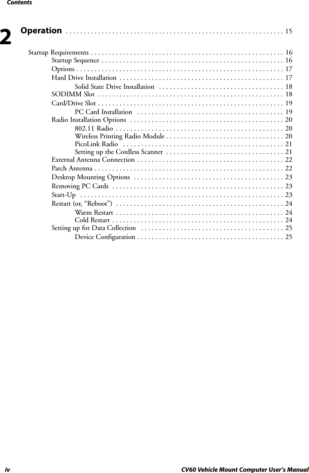
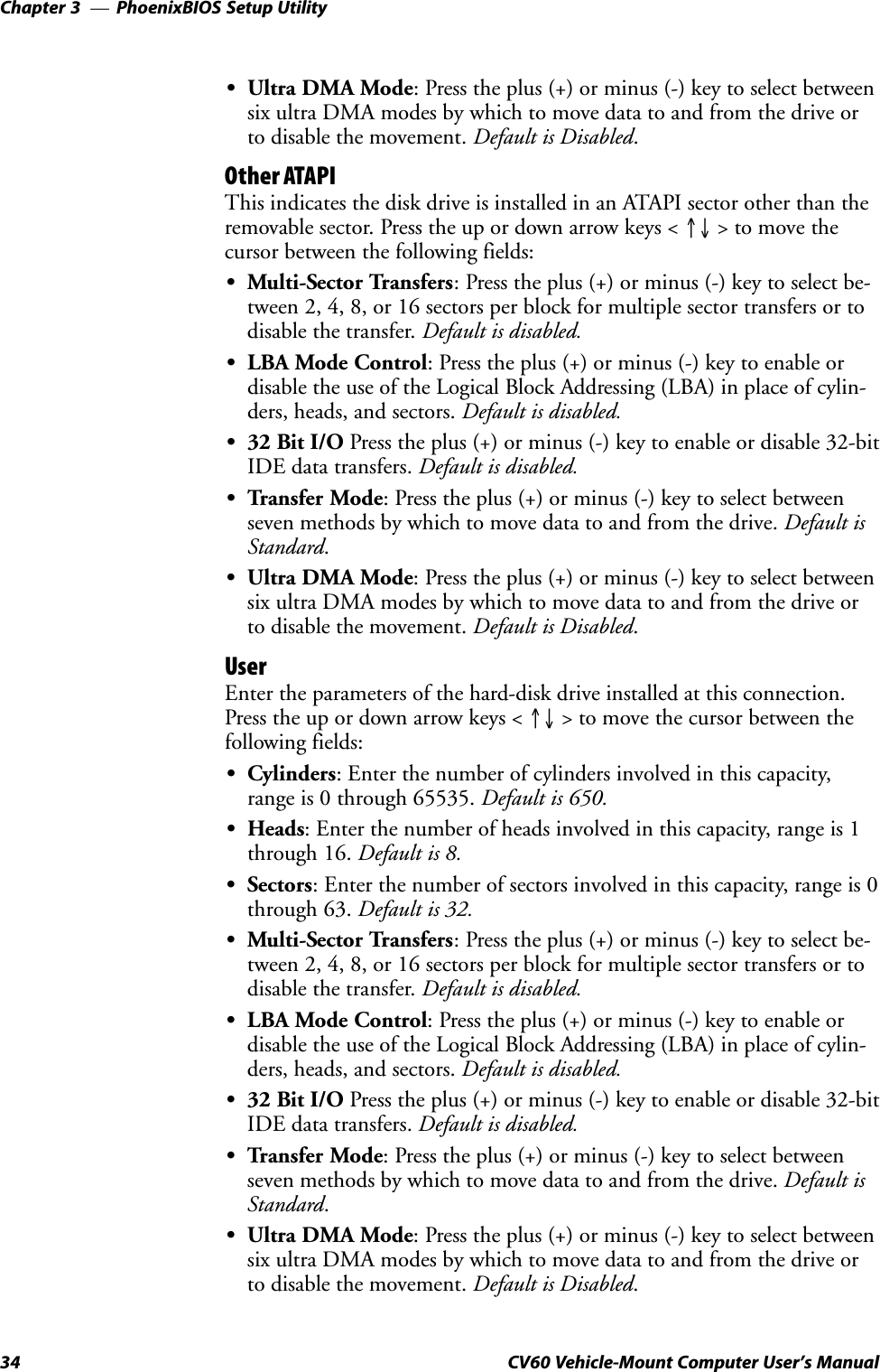
![PhoenixBIOS Setup UtilityChapter —340 CV60 Vehicle-Mount Computer User's ManualExitUse this menu to access exit options, settings, and version information.Press the up or down arrow keys < ↑↓ > to move the cursor between deĆvices. Press the left or right arrow keys < ←/→ > to move the cursor toanother menu.Exit Saving ChangesSelect this option to exit the PSU and save your changes to CMOS. Press[Enter] to select the option, then press [Yes] to continue. Press [No] toreturn to the Exit menu.Exit Discarding ChangesSelect this option to exit the PSU without saving the data to CMOS. Press[Enter] to select the option, then press [Yes] to continue. Press [No] toreturn to the Exit menu.Load Setup DefaultsSelect this option to load the default values for all setup items. Press [EnĆter] to select the option, then press [Yes] to continue. Press [No] to returnto the Exit menu.Discard ChangesSelect this option to discard all current changes and load previous valuesfrom CMOS for all setup items. Press [Enter] to select the option, thenpress [Yes] to continue. Press [No] to return to the Exit menu.Save ChangesSelect this option to save current changes to CMOS without exiting thePSU. Press [Enter] to select the option, then press [Yes] to continue. Press[No] to return to the Exit menu.](https://usermanual.wiki/Intermec-Technologies/802MIAG-CV60/User-Guide-479504-Page-52.png)


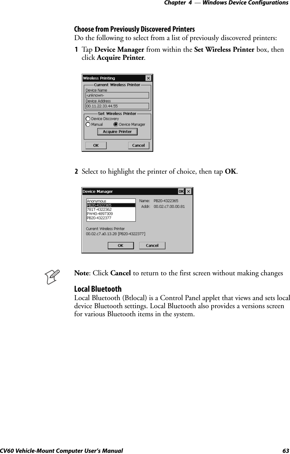
![Windows Device ConfigurationsChapter —462 CV60 Vehicle-Mount Computer User's ManualEnter the Remote Device AddressIf you know the Bluetooth Device Address of the printer you want to use,you can avoid Device Discovery and perform a manual setup.1Select Manual from within the Set Wireless Printer box, then click AcĆquire Printer.2Type the address of your device in the field, then click OK.When you set your printer manually, your device does not receive theprinter name. Therefore, "-unknown-" is displayed under Device Nameunless you enter the correct value in to the registry in some other way.HKEY_LOCAL_MACHINE\Software\Intermec\Bluetooth\WirelessPrintingSRemoteDeviceAddress [String] - ex. 0002c7a01328SRemoteDeviceAddress [String] - ex. PB20-4322377SWPPort [String] - ex. COM6:WPPort is the COM port to use in a call to CreateFile.wp_quickset also alerts BTCC of Wireless Printer changes. When a newwireless printer is set, wp_quickset calls BTCC, which then deregisters theexisting port (if necessary) and registers a new one based on the updatedremote Bluetooth device address.Note: Click Cancel to return to the first screen without making changes](https://usermanual.wiki/Intermec-Technologies/802MIAG-CV60/User-Guide-479504-Page-74.png)
![Windows Device ConfigurationsChapter —464 CV60 Vehicle-Mount Computer User's ManualFrom the CV60 desktop, select Start > Settings > Control Panel, thendoubleĆclick the Local Bluetooth desktop icon.SDevice Name This provides the friendly" name of your CV60.SDevice AddressDevice address is universally unique and cannot be changed. ReadĆonly.SDiscoverableCheck this box to make your CV60 discoverable to other Bluetooth deĆvices. The default is for the CV60 to be undiscoverable since it does notoffer any incoming services out of the box.SConnectableCheck this box to allow other Bluetooth devices to connect to yourCV60. The default is for the CV60 to be unconnectable since it doesnot offer any incoming services out of the box.SClass of DeviceThis sets how your CV60 appears to other devices during a device disĆcovery. The default is 0x920100 which specifies the CV60 is a PC capaĆble of services of information, object transfer, and networking. Note thatthough the CV60 identifies itself as having service classes, these services arenot supported as of this publication.HKEY_LOCAL_MACHINE\Software\Intermec\Network\BluetoothSDiscoverable [DWORD] - 0=FALSE, 1=TRUE (Default is false)SConnectable [DWORD] - 0=FALSE, 1=TRUE (Default is false)SDeviceName [String] - ex. 720-6025320 not yet implementedSCoD [?] - ex. ? not yet implementedWindows XPInformation that pertains to the Windows XP and Windows XP EmĆbedded operating systems is not available as of this publication.](https://usermanual.wiki/Intermec-Technologies/802MIAG-CV60/User-Guide-479504-Page-76.png)
![Windows Device ConfigurationsChapter —468 CV60 Vehicle-Mount Computer User's Manual2Tap your stylus firmly at the center of the crosshairs target. Continuethe process as the crosshair moves to the upperĆleft corner, the bottomĆleft, the bottomĆright, and upperĆright corners of the screen.3After all targets are tapped, a message appears to indicate that new calĆibration settings have been measured. Press [Enter] on the external keyĆboard to accept the new settings and return to the Stylus Propertiesscreen, or press [Esc] to do another calibration.4Tap OK to close the Stylus Properties screen.](https://usermanual.wiki/Intermec-Technologies/802MIAG-CV60/User-Guide-479504-Page-80.png)
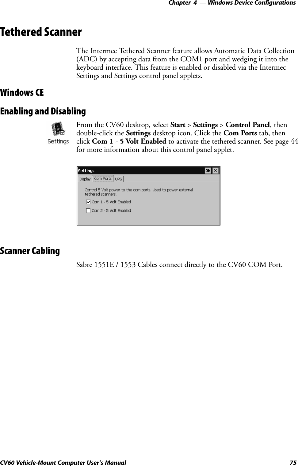
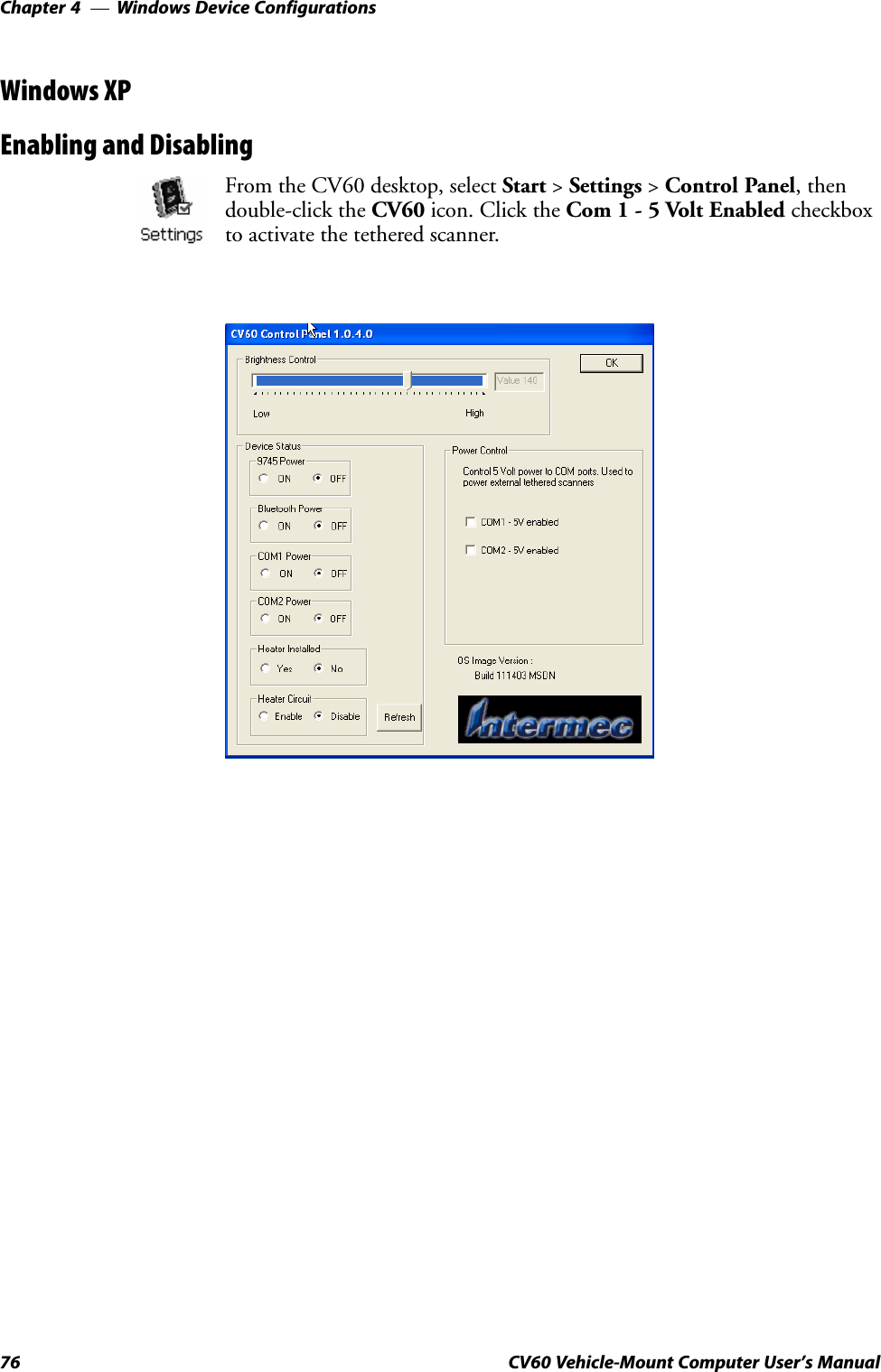
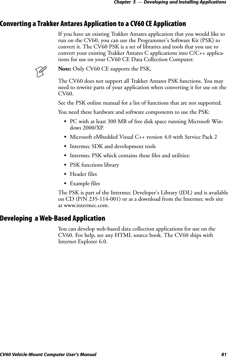
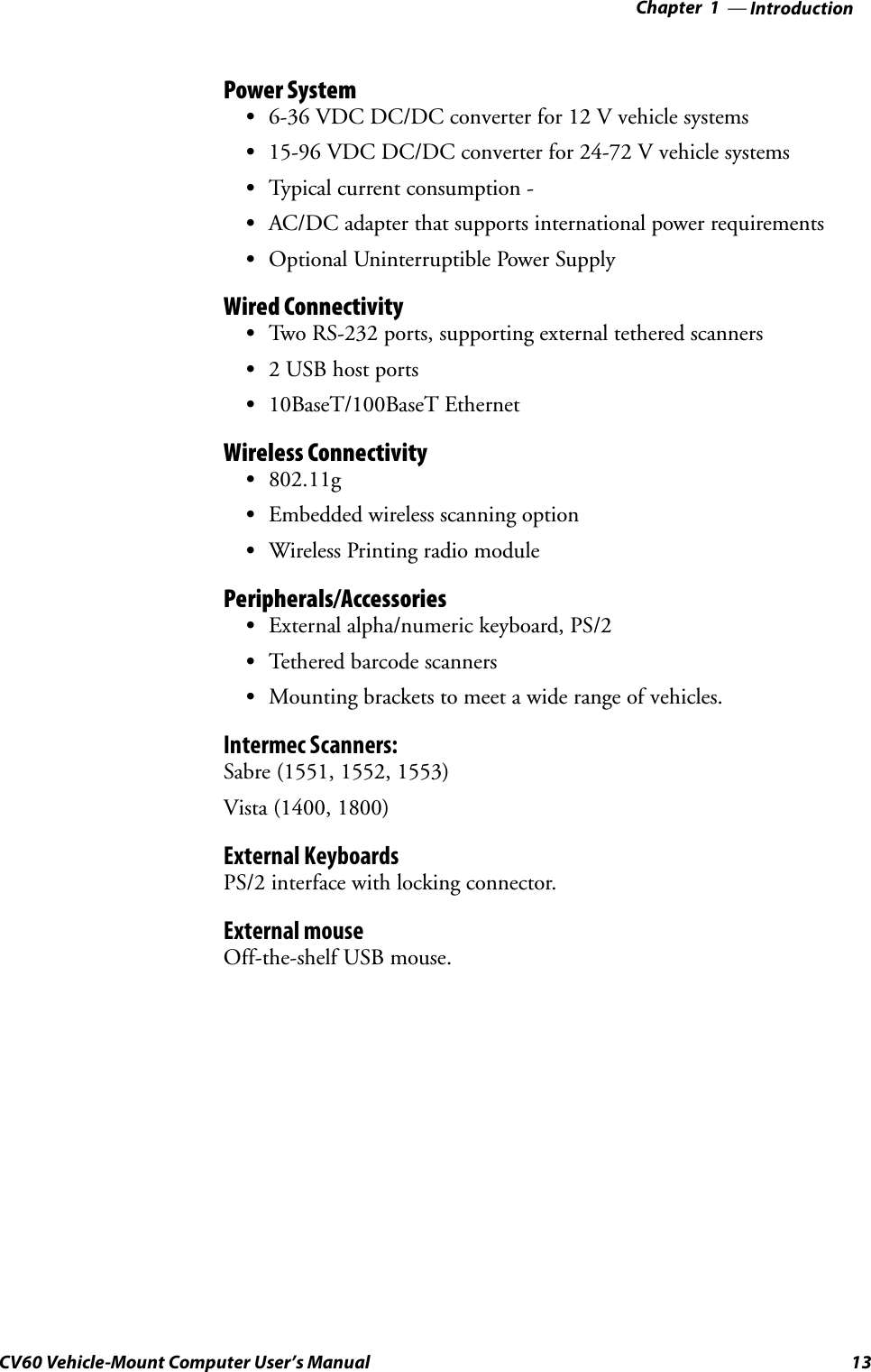
![Windows Device Configurations—Chapter 477CV60 Vehicle-Mount Computer User's ManualScanner CablingSabre 1551E / 1553 Cables connect directly to the CV60 COM Port.When enabled, the 1551/1553 menu option has these capabilities:SGrid Data Editing is available.SThe source of the symbology configurations is only available via theEasy Set command labels. Only the Virtual Wedge configurations can beconfigured via the Intermec Settings control panel applet.SMay transmit the data through the keyboard interface (via the VirtualWedge).SThe bar code APIs, defined in the IADC interface, are available to getbar code data from the bar code scanner. The following example showshow to programmatically collects bar code data:#include IADC.h" // Linked with ITCUUID.LIB#include ITCAdcMgmt.h" // Linked with ITCAdcDevMgmt.lib IADC* pIADC;HRESULT hrStatus = S_OK;// Create a ADC COM interface to collect bar code data from the 1551E/1553 // when the 1551/1553 menu option is enabled.hrStatus =ITCDeviceOpen(TEXT(ExtScanner"), // Name of the ADC device.IID_IADC, // COM interface to returnITC_DHDEVFLAG_READAHEAD, // Device's Flags(LPVOID *) &pIADC); // the returned interfaceif( SUCCEEDED(hrStatus) ){BYTE byteBuffer[MAX_LABEL_SIZE];DWORD dwLength = 0;HRESULT hr = pIDC->Read(byteBuffer, // Buffer to put the ADC data.MAX_LABEL_SIZE, // Size of pDataBuffer in bytes.&dwLength, // Number bytes returned.NULL, // Time stamp of the received data. NULL.INFINITE // Number of milliseconds to wait.);}when done using this COM interface, delete it:ITCDeviceClose( (IUnknown **) pIADC);](https://usermanual.wiki/Intermec-Technologies/802MIAG-CV60/User-Guide-479504-Page-89.png)