Intermec Technologies 802MIAG-CV60 802MIAG-CV60 User Manual BeforeYouBegin
Intermec Technologies Corporation 802MIAG-CV60 BeforeYouBegin
Users Manual
CV60 Vehicle Mount
Computer
User's Manual
ii CV60 Vehicle Mount Computer User's Manual
Intermec Technologies Corporation
Corporate Headquarters Cedar Rapids Technical Communications Department
6001 36th Ave. W. 550 Second Street SE
Everett, WA 98203 Cedar Rapids, IA 52401
U.S.A. U.S.A.
www.intermec.com
The information contained herein is proprietary and is provided solely for the purpose of allowing customers
to operate and service Intermec-manufactured equipment and is not to be released, reproduced, or used for
any other purpose without written permission of Intermec.
Information and specifications contained in this document are subject to change without prior notice and do
not represent a commitment on the part of Intermec Technologies Corporation.
E 2003 by Intermec Technologies Corporation. All rights reserved.
The word Intermec, the Intermec logo, Norand, ArciTech, CrossBar, Data Collection Browser, dcBrowser,
Duratherm, EasyCoder, EasyLAN, Enterprise Wireless LAN, EZBuilder, Fingerprint, i-gistics, INCA (under
license), InterDriver, Intermec Printer Network Manager, IRL, JANUS, LabelShop, Mobile Framework,
MobileLAN, Nor*Ware, Pen*Key, Precision Print, PrintSet, RoutePower, TE 2000, Trakker Antares, UAP,
Universal Access Point, and Virtual Wedge are either trademarks or registered trademarks of Intermec
Technologies Corporation.
Throughout this manual, trademarked names may be used. Rather than put a trademark (™ or ®) symbol in
every occurrence of a trademarked name, we state that we are using the names only in an editorial fashion,
and to the benefit of the trademark owner, with no intention of infringement.
There are U.S. and foreign patents pending.
Wi-Fi is a registered certification mark of the Wi-Fi Alliance.
Microsoft, Windows, and the Windows logo are registered trademarks of Microsoft Corporation in the
United States and/or other countries.
Bluetooth is a trademark of Bluetooth SIG, Inc., U.S.A.
Contents
iiiCV60 Vehicle Mount Computer User’s Manual
Contents
Before You Begin ix.........................................................
Safety Summary ix...................................................
Donotrepairoradjustalone ix...................................
First aid ix...................................................
Resuscitation ix...............................................
Energized equipment ix.........................................
Safety Icons x.......................................................
Global Services and Support xi..........................................
Warranty Information xi........................................
Web Support xi...............................................
Telephone Support xi...........................................
WhoShouldReadthisManual? xii.......................................
Related Documents xii.................................................
Introduction
1..........................................................
Introducing the CV60 Vehicle Mount Computer 2.................................
Features 3..........................................................
Unpacking the CV60 Vehicle Mount Computer 4...........................
Accessories for the CV60 Vehicle Mount Computer 5........................
Locating the Data Collection PC Connectors 6.............................
Card/Drive Slot 8....................................................
Hard Drive/Memory Location 9........................................
SODIMM Memory Slot 9.............................................
AC-DC Power Supply 10...............................................
DC-DC Power Supplies 10.............................................
Maintenance 11...............................................
Cleaning 11...................................................
Daily Checks 11...............................................
Specifications 12......................................................
Size 12.......................................................
Environmental 12..............................................
Processor/Memory/Storage 12.....................................
System Software 12.............................................
Power System 13...............................................
Wired Connectivity 13..........................................
Wireless Connectivity 13.........................................
Peripherals/Accessories 13........................................
FCC Notice 14................................................
1
Contents
iv CV60 Vehicle Mount Computer User's Manual
Operation 15. . . . . . . . . . . . . . . . . . . . . . . . . . . . . . . . . . . . . . . . . . . . . . . . . . . . . . . . . . . . .
Startup Requirements 16. . . . . . . . . . . . . . . . . . . . . . . . . . . . . . . . . . . . . . . . . . . . . . . . . . . . . .
Startup Sequence 16. . . . . . . . . . . . . . . . . . . . . . . . . . . . . . . . . . . . . . . . . . . . . . . . . . .
Options 17. . . . . . . . . . . . . . . . . . . . . . . . . . . . . . . . . . . . . . . . . . . . . . . . . . . . . . . . . .
Hard Drive Installation 17. . . . . . . . . . . . . . . . . . . . . . . . . . . . . . . . . . . . . . . . . . . . . .
Solid State Drive Installation 18. . . . . . . . . . . . . . . . . . . . . . . . . . . . . . . . . . .
SODIMM Slot 18. . . . . . . . . . . . . . . . . . . . . . . . . . . . . . . . . . . . . . . . . . . . . . . . . . . .
Card/Drive Slot 19. . . . . . . . . . . . . . . . . . . . . . . . . . . . . . . . . . . . . . . . . . . . . . . . . . . .
PC Card Installation 19. . . . . . . . . . . . . . . . . . . . . . . . . . . . . . . . . . . . . . . . .
Radio Installation Options 20. . . . . . . . . . . . . . . . . . . . . . . . . . . . . . . . . . . . . . . . . . .
802.11 Radio 20. . . . . . . . . . . . . . . . . . . . . . . . . . . . . . . . . . . . . . . . . . . . . . .
Wireless Printing Radio Module 20. . . . . . . . . . . . . . . . . . . . . . . . . . . . . . . . .
PicoLink Radio 21. . . . . . . . . . . . . . . . . . . . . . . . . . . . . . . . . . . . . . . . . . . . .
Setting up the Cordless Scanner 21. . . . . . . . . . . . . . . . . . . . . . . . . . . . . . . . .
External Antenna Connection 22. . . . . . . . . . . . . . . . . . . . . . . . . . . . . . . . . . . . . . . . .
Patch Antenna 22. . . . . . . . . . . . . . . . . . . . . . . . . . . . . . . . . . . . . . . . . . . . . . . . . . . . .
Desktop Mounting Options 23. . . . . . . . . . . . . . . . . . . . . . . . . . . . . . . . . . . . . . . . . .
Removing PC Cards 23. . . . . . . . . . . . . . . . . . . . . . . . . . . . . . . . . . . . . . . . . . . . . . . .
Start-Up 23. . . . . . . . . . . . . . . . . . . . . . . . . . . . . . . . . . . . . . . . . . . . . . . . . . . . . . . . .
Restart (or, Reboot") 24. . . . . . . . . . . . . . . . . . . . . . . . . . . . . . . . . . . . . . . . . . . . . . .
Warm Restart 24. . . . . . . . . . . . . . . . . . . . . . . . . . . . . . . . . . . . . . . . . . . . . . .
Cold Restart 24. . . . . . . . . . . . . . . . . . . . . . . . . . . . . . . . . . . . . . . . . . . . . . . .
Setting up for Data Collection 25. . . . . . . . . . . . . . . . . . . . . . . . . . . . . . . . . . . . . . . .
Device Configuration 25. . . . . . . . . . . . . . . . . . . . . . . . . . . . . . . . . . . . . . . . .
2
Contents
vCV60 Vehicle Mount Computer User's Manual
PhoenixBIOS Setup Utility 27. . . . . . . . . . . . . . . . . . . . . . . . . . . . . . . . . . . . . . . . . . .
General Information 28. . . . . . . . . . . . . . . . . . . . . . . . . . . . . . . . . . . . . . . . . . . . . . . . . . . . . . .
Main 29. . . . . . . . . . . . . . . . . . . . . . . . . . . . . . . . . . . . . . . . . . . . . . . . . . . . . . . . . . . . . . . . . .
System Time 29. . . . . . . . . . . . . . . . . . . . . . . . . . . . . . . . . . . . . . . . . . . . . . . . . . . . . .
System Date 29. . . . . . . . . . . . . . . . . . . . . . . . . . . . . . . . . . . . . . . . . . . . . . . . . . . . . .
Primary Master 30. . . . . . . . . . . . . . . . . . . . . . . . . . . . . . . . . . . . . . . . . . . . . . . . . . . .
Auto 30. . . . . . . . . . . . . . . . . . . . . . . . . . . . . . . . . . . . . . . . . . . . . . . . . . . . . .
None 30. . . . . . . . . . . . . . . . . . . . . . . . . . . . . . . . . . . . . . . . . . . . . . . . . . . . .
CDĆROM 30. . . . . . . . . . . . . . . . . . . . . . . . . . . . . . . . . . . . . . . . . . . . . . . . .
IDE Removable 30. . . . . . . . . . . . . . . . . . . . . . . . . . . . . . . . . . . . . . . . . . . . .
ATAPI Removable 31. . . . . . . . . . . . . . . . . . . . . . . . . . . . . . . . . . . . . . . . . . .
Other ATAPI 31. . . . . . . . . . . . . . . . . . . . . . . . . . . . . . . . . . . . . . . . . . . . . . .
User 32. . . . . . . . . . . . . . . . . . . . . . . . . . . . . . . . . . . . . . . . . . . . . . . . . . . . . .
Secondary Master 32. . . . . . . . . . . . . . . . . . . . . . . . . . . . . . . . . . . . . . . . . . . . . . . . . .
Auto 32. . . . . . . . . . . . . . . . . . . . . . . . . . . . . . . . . . . . . . . . . . . . . . . . . . . . . .
None 32. . . . . . . . . . . . . . . . . . . . . . . . . . . . . . . . . . . . . . . . . . . . . . . . . . . . .
CDĆROM 32. . . . . . . . . . . . . . . . . . . . . . . . . . . . . . . . . . . . . . . . . . . . . . . . .
IDE Removable 33. . . . . . . . . . . . . . . . . . . . . . . . . . . . . . . . . . . . . . . . . . . . .
ATAPI Removable 33. . . . . . . . . . . . . . . . . . . . . . . . . . . . . . . . . . . . . . . . . . .
Other ATAPI 34. . . . . . . . . . . . . . . . . . . . . . . . . . . . . . . . . . . . . . . . . . . . . . .
User 34. . . . . . . . . . . . . . . . . . . . . . . . . . . . . . . . . . . . . . . . . . . . . . . . . . . . . .
Memory Cache 35. . . . . . . . . . . . . . . . . . . . . . . . . . . . . . . . . . . . . . . . . . . . . . . . . . . .
Memory Cache 35. . . . . . . . . . . . . . . . . . . . . . . . . . . . . . . . . . . . . . . . . . . . . .
Cache System/Video BIOS Areas 35. . . . . . . . . . . . . . . . . . . . . . . . . . . . . . . .
Cache Base 0ć512k, 512kć640k, Extended Memory Area 35. . . . . . . . . . . . .
Boot Features 35. . . . . . . . . . . . . . . . . . . . . . . . . . . . . . . . . . . . . . . . . . . . . . . . . . . . .
Summary Screen 35. . . . . . . . . . . . . . . . . . . . . . . . . . . . . . . . . . . . . . . . . . . . .
BootĆTime Diagnostic Screen 35
. . . . . . . . . . . . . . . . . . . . . . . . . . . . . . . . . . .
QuickBoot Mode 35. . . . . . . . . . . . . . . . . . . . . . . . . . . . . . . . . . . . . . . . . . . .
Advanced 36. . . . . . . . . . . . . . . . . . . . . . . . . . . . . . . . . . . . . . . . . . . . . . . . . . . . . . . . . . . . . . .
Advanced Chipset Control 36. . . . . . . . . . . . . . . . . . . . . . . . . . . . . . . . . . . . . . . . . . .
Video Boot Type 36. . . . . . . . . . . . . . . . . . . . . . . . . . . . . . . . . . . . . . . . . . . .
Enable Memory Gap 36. . . . . . . . . . . . . . . . . . . . . . . . . . . . . . . . . . . . . . . . .
Frequency Ratio 36. . . . . . . . . . . . . . . . . . . . . . . . . . . . . . . . . . . . . . . . . . . . .
I/O Device Configuration 36. . . . . . . . . . . . . . . . . . . . . . . . . . . . . . . . . . . . . . . . . . . .
Serial Ports 36. . . . . . . . . . . . . . . . . . . . . . . . . . . . . . . . . . . . . . . . . . . . . . . . .
Panel Heater 36. . . . . . . . . . . . . . . . . . . . . . . . . . . . . . . . . . . . . . . . . . . . . . . .
Picolink 36. . . . . . . . . . . . . . . . . . . . . . . . . . . . . . . . . . . . . . . . . . . . . . . . . . .
Legacy USB Support 37. . . . . . . . . . . . . . . . . . . . . . . . . . . . . . . . . . . . . . . . . . . . . . . .
Reset Configuration Data 37. . . . . . . . . . . . . . . . . . . . . . . . . . . . . . . . . . . . . . . . . . . .
FirstWare Authentication Level 37. . . . . . . . . . . . . . . . . . . . . . . . . . . . . . . . . . . . . . . .
PC Card Boot Support 37. . . . . . . . . . . . . . . . . . . . . . . . . . . . . . . . . . . . . . . . . . . . . .
Security 38. . . . . . . . . . . . . . . . . . . . . . . . . . . . . . . . . . . . . . . . . . . . . . . . . . . . . . . . . . . . . . . .
Set Supervisor Password 38. . . . . . . . . . . . . . . . . . . . . . . . . . . . . . . . . . . . . . . . . . . . . .
Boot 39. . . . . . . . . . . . . . . . . . . . . . . . . . . . . . . . . . . . . . . . . . . . . . . . . . . . . . . . . . . . . . . . . . .
3
Contents
vi CV60 Vehicle Mount Computer User's Manual
Exit 40. . . . . . . . . . . . . . . . . . . . . . . . . . . . . . . . . . . . . . . . . . . . . . . . . . . . . . . . . . . . . . . . . . .
Exit Saving Changes 40. . . . . . . . . . . . . . . . . . . . . . . . . . . . . . . . . . . . . . . . . . . . . . . .
Exit Discarding Changes 40. . . . . . . . . . . . . . . . . . . . . . . . . . . . . . . . . . . . . . . . . . . . .
Load Setup Defaults 40. . . . . . . . . . . . . . . . . . . . . . . . . . . . . . . . . . . . . . . . . . . . . . . .
Discard Changes 40. . . . . . . . . . . . . . . . . . . . . . . . . . . . . . . . . . . . . . . . . . . . . . . . . . .
Save Changes 40. . . . . . . . . . . . . . . . . . . . . . . . . . . . . . . . . . . . . . . . . . . . . . . . . . . . .
Reflash Procedure 41. . . . . . . . . . . . . . . . . . . . . . . . . . . . . . . . . . . . . . . . . . . . . . . . . . . . . . . . .
Windows CE 41. . . . . . . . . . . . . . . . . . . . . . . . . . . . . . . . . . . . . . . . . . . . . . . . . . . . . .
Windows XP 41. . . . . . . . . . . . . . . . . . . . . . . . . . . . . . . . . . . . . . . . . . . . . . . . . . . . . .
Contents
viiCV60 Vehicle Mount Computer User's Manual
Windows Device Configurations 43. . . . . . . . . . . . . . . . . . . . . . . . . . . . . . . . . . . . .
AutoIP/DHCP 44. . . . . . . . . . . . . . . . . . . . . . . . . . . . . . . . . . . . . . . . . . . . . . . . . . . . . . . . . . .
CV60 Settings 45. . . . . . . . . . . . . . . . . . . . . . . . . . . . . . . . . . . . . . . . . . . . . . . . . . . . . . . . . . .
Windows CE 45. . . . . . . . . . . . . . . . . . . . . . . . . . . . . . . . . . . . . . . . . . . . . . . . . . . . . .
Display 45. . . . . . . . . . . . . . . . . . . . . . . . . . . . . . . . . . . . . . . . . . . . . . . . . . . .
Com Ports 45. . . . . . . . . . . . . . . . . . . . . . . . . . . . . . . . . . . . . . . . . . . . . . . . .
UPS 46. . . . . . . . . . . . . . . . . . . . . . . . . . . . . . . . . . . . . . . . . . . . . . . . . . . . . .
System 46. . . . . . . . . . . . . . . . . . . . . . . . . . . . . . . . . . . . . . . . . . . . . . . . . . . .
Versions 46. . . . . . . . . . . . . . . . . . . . . . . . . . . . . . . . . . . . . . . . . . . . . . . . . . .
Windows XP 47. . . . . . . . . . . . . . . . . . . . . . . . . . . . . . . . . . . . . . . . . . . . . . . . . . . . . .
Brightness Status 47. . . . . . . . . . . . . . . . . . . . . . . . . . . . . . . . . . . . . . . . . . . .
Device Status 48. . . . . . . . . . . . . . . . . . . . . . . . . . . . . . . . . . . . . . . . . . . . . . .
UPS Service 48. . . . . . . . . . . . . . . . . . . . . . . . . . . . . . . . . . . . . . . . . . . . . . . .
Network Adapters 49. . . . . . . . . . . . . . . . . . . . . . . . . . . . . . . . . . . . . . . . . . . . . . . . . . . . . . . .
802.11b/g Communications 49. . . . . . . . . . . . . . . . . . . . . . . . . . . . . . . . . . . . . . . . . .
Wireless Printing 49. . . . . . . . . . . . . . . . . . . . . . . . . . . . . . . . . . . . . . . . . . . . . . . . . . .
Windows CE 50. . . . . . . . . . . . . . . . . . . . . . . . . . . . . . . . . . . . . . . . . . . . . . .
Windows XP 53. . . . . . . . . . . . . . . . . . . . . . . . . . . . . . . . . . . . . . . . . . . . . . .
Picolink Radio 54. . . . . . . . . . . . . . . . . . . . . . . . . . . . . . . . . . . . . . . . . . . . . . . . . . . . .
Stylus 55. . . . . . . . . . . . . . . . . . . . . . . . . . . . . . . . . . . . . . . . . . . . . . . . . . . . . . . . . . . . . . . . . .
Windows CE 55. . . . . . . . . . . . . . . . . . . . . . . . . . . . . . . . . . . . . . . . . . . . . . . . . . . . . .
DoubleĆTap 55. . . . . . . . . . . . . . . . . . . . . . . . . . . . . . . . . . . . . . . . . . . . . . . .
Calibration 55. . . . . . . . . . . . . . . . . . . . . . . . . . . . . . . . . . . . . . . . . . . . . . . . .
Windows XP 57. . . . . . . . . . . . . . . . . . . . . . . . . . . . . . . . . . . . . . . . . . . . . . . . . . . . . .
DoubleĆTap 57. . . . . . . . . . . . . . . . . . . . . . . . . . . . . . . . . . . . . . . . . . . . . . . .
Calibration 57. . . . . . . . . . . . . . . . . . . . . . . . . . . . . . . . . . . . . . . . . . . . . . . . .
TCP/IP 60. . . . . . . . . . . . . . . . . . . . . . . . . . . . . . . . . . . . . . . . . . . . . . . . . . . . . . . . . . . . . . . .
Windows CE 60. . . . . . . . . . . . . . . . . . . . . . . . . . . . . . . . . . . . . . . . . . . . . . . . . . . . . .
Windows XP 61. . . . . . . . . . . . . . . . . . . . . . . . . . . . . . . . . . . . . . . . . . . . . . . . . . . . . .
Tethered Scanner 63. . . . . . . . . . . . . . . . . . . . . . . . . . . . . . . . . . . . . . . . . . . . . . . . . . . . . . . . .
Enabling and Disabling 63. . . . . . . . . . . . . . . . . . . . . . . . . . . . . . . . . . . . . . . . . . . . . .
Scanner Cabling 63. . . . . . . . . . . . . . . . . . . . . . . . . . . . . . . . . . . . . . . . . . . . . . . . . . .
Limitations and Capabilities 63. . . . . . . . . . . . . . . . . . . . . . . . . . . . . . . . . . . . . . . . . .
4
Contents
viii CV60 Vehicle Mount Computer User's Manual
Developing and Installing Applications 65. . . . . . . . . . . . . . . . . . . . . . . . . . . . .
Developing Applications for the CV60 66. . . . . . . . . . . . . . . . . . . . . . . . . . . . . . . . . . . . . . . . .
Developing a New Application for the CV60 66. . . . . . . . . . . . . . . . . . . . . . . . . . . . .
Converting a Trakker Antares Application to a CV60 CE Application 67. . . . . . . . . .
Developing a Web-Based Application 67. . . . . . . . . . . . . . . . . . . . . . . . . . . . . . . . . . .
Installing Applications on the CV60 68. . . . . . . . . . . . . . . . . . . . . . . . . . . . . . . . . . . . . . . . . .
All CV60: 68. . . . . . . . . . . . . . . . . . . . . . . . . . . . . . . . . . . . . . . . . . . . . . . . . . . . . . . .
Installing Applications Using Wavelink Avalanche 68. . . . . . . . . . . . . . . . . . .
To use Avalanche to remotely manage the CV60 68. . . . . . . . . . . . . . . . . . . .
CV60 CE only: 68. . . . . . . . . . . . . . . . . . . . . . . . . . . . . . . . . . . . . . . . . . . . . . . . . . . .
Using ActiveSync to Install Applications 68. . . . . . . . . . . . . . . . . . . . . . . . . . .
Installing ActiveSync and Establishing a Partnership 69. . . . . . . . . . . . . . . . . . . . . . . .
To install ActiveSync and establish a partnership 69. . . . . . . . . . . . . . . . . . . .
The Microsoft ActiveSync Screen 70. . . . . . . . . . . . . . . . . . . . . . . . . . . . . . . . . . . . . .
Using ActiveSync to Copy Files and Install Applications 70. . . . . . . . . . . . . .
To install an application on the CV60 CE using ActiveSync 70. . . . . . . . . . .
CV60 XP/XPE: 71. . . . . . . . . . . . . . . . . . . . . . . . . . . . . . . . . . . . . . . . . . . . . . . . . .
Mapping a network drive: 71. . . . . . . . . . . . . . . . . . . . . . . . . . . . . . . . . . . . .
Connector Pinouts 73. . . . . . . . . . . . . . . . . . . . . . . . . . . . . . . . . . . . . . . . . . . . . . . . . . . .
Connectors 74. . . . . . . . . . . . . . . . . . . . . . . . . . . . . . . . . . . . . . . . . . . . . . . . . . . . . . . . . . . . . .
Connectors 74. . . . . . . . . . . . . . . . . . . . . . . . . . . . . . . . . . . . . . . . . . . . . . . . . . . . . . .
COM Port Pinout 75. . . . . . . . . . . . . . . . . . . . . . . . . . . . . . . . . . . . . . . . . . .
Keyboard PS/2 76. . . . . . . . . . . . . . . . . . . . . . . . . . . . . . . . . . . . . . . . . . . . .
Ethernet 77. . . . . . . . . . . . . . . . . . . . . . . . . . . . . . . . . . . . . . . . . . . . . . . . . . .
77. . . . . . . . . . . . . . . . . . . . . . . . . . . . . . . . . . . . . . . . . . . . . . . . . . . . . . . . . .
USB Connectors 78. . . . . . . . . . . . . . . . . . . . . . . . . . . . . . . . . . . . . . . . . . . .
Audio Connections 78. . . . . . . . . . . . . . . . . . . . . . . . . . . . . . . . . . . . . . . . . . . . . . . . .
Microphone / Headphone 78. . . . . . . . . . . . . . . . . . . . . . . . . . . . . . . . . . . . .
Power Connector Pin out 79. . . . . . . . . . . . . . . . . . . . . . . . . . . . . . . . . . . . . .
5
6
Before You Begin
ixCV60 Vehicle Mount Computer User's Manual
Before You Begin
This section provides you with safety information, technical support
information, and sources for additional product information.
Safety Summary
Your safety is extremely important. Read and follow all warnings and
cautions in this document before handling and operating Intermec
equipment. You can be seriously injured, and equipment and data can be
damaged if you do not follow the safety warnings and cautions.
Do not repair or adjust alone
Do not repair or adjust energized equipment alone under any
circumstances. Someone capable of providing first aid must always be
present for your safety.
First aid
Always obtain first aid or medical attention immediately after an injury.
Never neglect an injury, no matter how slight it seems.
Resuscitation
Begin resuscitation immediately if someone is injured and stops breathing.
Any delay could result in death. To work on or near high voltage, you
should be familiar with approved industrial first aid methods.
Energized equipment
Never work on energized equipment unless authorized by a responsible
authority. Energized electrical equipment is dangerous. Electrical shock
from energized equipment can cause death. If you must perform
authorized emergency work on energized equipment, be sure that you
comply strictly with approved safety regulations.

Before You Begin
x CV60 Vehicle Mount Computer User's Manual
Safety Icons
This section explains how to identify and understand dangers, warnings,
cautions, and notes that are in this manual. You may also see icons that tell
you when to follow ESD procedures and when to take special precautions
for handling optical parts.
A warning alerts you of an operating procedure, practice, condition, or
statement that must be strictly observed to avoid death or serious injury to
the persons working on the equipment.
Avertissement: Un avertissement vous avertit d'une procédure de
fonctionnement, d'une méthode, d'un état ou d'un rapport qui doit être
strictement respecté pour éviter l'occurrence de mort ou de blessures graves
aux personnes manupulant l'équipement.
A caution alerts you to an operating procedure, practice, condition, or
statement that must be strictly observed to prevent equipment damage or
destruction, or corruption or loss of data.
Attention: Une précaution vous avertit d'une procédure de
fonctionnement, d'une méthode, d'un état ou d'un rapport qui doit être
strictement respecté pour empêcher l'endommagement ou la destruction
de l'équipement, ou l'altération ou la perte de données.
Note: Notes either provide extra information about a topic or contain
special instructions for handling a particular condition or set of
circumstances.

Before You Begin
xiCV60 Vehicle Mount Computer User's Manual
Global Services and Support
Warranty Information
To understand the warranty for your Intermec product, visit the Intermec
web site at http://www.intermec.com and click Service & Support. The
Intermec Global Sales & Service page appears. From the Service &
Support menu, move your pointer over Support, and then click
Warranty.
Disclaimer of warranties: The sample code included in this document is
presented for reference only. The code does not necessarily represent
complete, tested programs. The code is provided as is with all faults." All
warranties are expressly disclaimed, including the implied warranties of
merchantability and fitness for a particular purpose.
Web Support
Visit the Intermec web site at http://www.intermec.com to download our
current manuals in PDF format. To order printed versions of the Intermec
manuals, contact your local Intermec representative or distributor.
Visit the Intermec technical knowledge base (Knowledge Central) at
http://intermec.custhelp.com to review technical information or to request
technical support for your Intermec product.
Telephone Support
These services are available from Intermec Technologies Corporation.
Service Description
In the U.S.A. and Canada
call 1Ć800Ć755Ć5505
and choose this option
Factory Repair and
OnĆsite Repair
Request a return authorization
number for authorized service
center repair, or request an
onĆsite repair technician.
1
Technical Support Get technical support on your
Intermec product.
2
Service Contract
Status
Inquire about an existing
contract, renew a contract, or ask
invoicing questions.
3
Schedule Site Surveys
or Installations
Schedule a site survey, or request
a product or system installation.
4
Ordering Products Talk to sales administration,
place an order, or check the
status of your order.
5
Outside the U.S.A. and Canada, contact your local Intermec
representative. To search for your local representative, from the Intermec
web site, click Contact.

Before You Begin
xii CV60 Vehicle Mount Computer User's Manual
Who Should Read this Manual?
This guide provides you with information about the features of the CV60
Vehicle Mount Computer, and how to install, configure, operate, mainĆ
tain, and troubleshoot it.
Before you install and configure the CV60, you should be familiar with
Windows XP or Windows CE, your network and general networking
terms, such as IP address and network naming conventions.
Related Documents
Document Title Part Number
CV60 QuickStart Guide 962Ć054-072
Intermec Computer Command Reference 073529
CV60 Vehicle Power Supply Installation Guide 962-054-076
The Intermec web site at http://www.intermec.com contains many of our
documents that you can download in PDF format.
To order printed versions of the Intermec manuals, contact your local
Intermec representative or distributor.
Patent Information
Product is covered by one or more of the following patents:
4,455,523; 5,627,360; 4,553,081; 5,657,317; 4,709,202; 5,671,436;
4,845,419; 5,684,290; 4,961,043; 5,777,309; 5,195,183; 5,793,604;
5,216,233; 5,805,807; 5,218,187; 5,818,027; 5,218,188; 5,821,523;
5,227,614; 5,828,052; 5,241,488; 5,831,819; 5,278,487; 5,834,753;
5,322,991; 5,841,121; 5,331,136; 5,844,222; 5,331,580; 5,883,492;
5,349,678; 5,883,493; 5,397,885; 5,886,338; 5,371,858; 5,889,386;
5,373,478; 5,898,162; 5,410,141; 5,969,328; 5,488,575; 5,986,435;
5,500,516; 6,075,340; 5,504,367; 6,109,528; 5,508,599; 6,158,661;
5,530,619; 6,234,395; 5,567,925; 6,244,512; 5,568,645; 6,330,975;
5,592,512; 6,431,451; 5,598,007, 6,497,368; 5,617,343; 6,538,413.
There may be other U.S. and foreign patents pending.

1CV60 Vehicle-Mount Computer User’s Manual
Introduction
1
This chapter outlines the features and specifications of the CV60
Vehicle-Mount Computer.
IntroductionChapter —1
2 CV60 Vehicle-Mount Computer User’s Manual
Introducing the CV60 Vehicle-Mount Computer
The CV60 Vehicle-Mount Computer is a rugged PC computing device
consisting of a 12.1-inch color, SVGA LCD display with touch screen for
data input and menu navigation.
Communication options include connectivity through two RS-232 serial
ports, USB (host), and Ethernet Wireless network connectivity is enabled
through multiple LAN radio options.
Peripherals supported include PS/2 keyboard, USB mouse, external head-
set, wired RS-232 scanners, wireless scanners via proprietary wireless base
station, wireless printers, and USB data recovery drives.
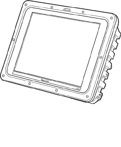
CV60 Vehicle-Mount Computer
Introduction
—Chapter 1
3CV60 Vehicle-Mount Computer User’s Manual
Features
SWi-Fi certified for interoperability with other 802.11g wireless LAN
devices.
SOperating Systems: Windows CE. NET (4.2), Windows XP Em-
bedded, Windows XP Professional Edition
SIntel® Pentium® III 800 MHz embedded
S128MB base SDRAM memory 256/384 MB optional upgrade
SDisplay: 12.1” TFT 800*600 SVGA
SResistive touch panel
SRotating or solid-state IDE hard drive
SSolid-StatePCMCIATypeIIflashstoragecard
SWireless Printing for cordless accessories and printing
SIntegrated antennas
SRecovery CD provided by Intermec
SExternal USB boot support
SExternal headset jack
SSpeaker
SLocking I/O connectors
SHeater option for low temperature operation
IntroductionChapter —1
4 CV60 Vehicle-Mount Computer User’s Manual
Unpacking the CV60 Vehicle-Mount Computer
When you remove the data collection PC from its box, save the box and
shipping material in case you need to ship or store the data collection PC.
Check the contents of the box against the invoice for completeness and
contact your local Intermec service representative if there is a problem.
The CV60 shipping box contains:
SCV60 Vehicle-Mount Computer (P/N 245-232-101)
SDocumentation (P/N 962-054-072)
The CV60 display allows user input and menu navigation via resistive
touchscreen. The touch panel is field replaceable.
Refer to the CV60 Touch Panel Replacement Instructions (P/N
962-054-078) for information on replacing the touch panel.
Introduction
—Chapter 1
5CV60 Vehicle-Mount Computer User’s Manual
Accessories for the CV60 Vehicle-Mount Computer
You can use these accessories (sold and ordered separately) with the CV60
Vehicle-Mount Computer:
SAC power supply Use the AC power supply (P/N 851-070-001) to
powerthedatacollectionPCwhenitisinthedesktopmounting
stand. The AC power supply is only for use in clean, dry, office-like
environments with temperatures from 10° C to 40° C (50° F to 104°
F). The power supply comes with a North American power cord. If
you are using the data collection PC outside North America, you
need to purchase the appropriate power cord for your local power
source.
SDC power supply There are two DC power supply kits that you can
use to power the data collection PC when it is mounted to a vehicle:
SHeater option kit (15-96 VDC) (P/N 203-665-002) or
(12-72VDC) (P/N 203-669-002).
SDesktop mounting stand The desktop mounting stand (P/N
203-664-001) attaches to your data collection PC to provide a stable
desktop platform. The desktop mounting stand is useful when you
have the data collection PC connected to your PC to develop applica-
tions.
SKeyboard The alphanumeric keyboard is backlit for view in low
lighting conditions (P/N 850-537-002) and supports a subset of the
available keys on a PC-AT keyboard. The CV60 ships with a key-
board overlay to match the application or language you ordered: En-
glish, Western European, or one of the three TE 2000 terminal
emulation options. You must use the keyboard accessory with the
Intermec TE 2000 terminal emulation applications.
SScanner cables Use the scanner cables to connect a scanning device
such as the 1550 and 1551 and 1553 laser scanners.
SKeyboard tray mount The keyboard tray (P/N G9A-KB000-01) is an
orderable option which allows mounting the CV60 keyboard directly to
the device.
SRemote keyboard mounting kit (P/N 203-564-001)
IntroductionChapter —1
6 CV60 Vehicle-Mount Computer User’s Manual
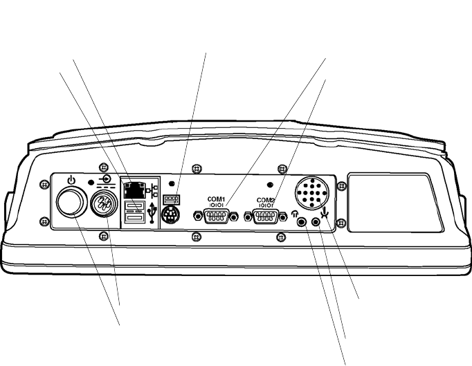
Locating the Data Collection PC Connectors
You connect power, a keyboard, scanner, and RS-232 serial devices to the
data collection PC ports that are located on the bottom panel of the CV60.
Connectors
The On/Off switch and all connectors are located on the bottom of the
CV60.
These include a power connector, two standard serial I/O connectors
(COM1 and COM2), a USB keyboard (USB) connector, and a network
(NET) connector.
Power Connector
Power Switch
Ethernet
USB
Speaker
Serial
Ports
Headphone
Microphone
PS/2 Keyboard
Speaker
A speaker is provided to allow standard PC sounds, as well as business audio
playback and record.
Microphone
This 2.5 mm connector accepts an external microphone.
USB Serial Port
The USB serial port accommodates an external USB standard mouse and
keyboard. Other USB devices which do not have locking connectors can
beused,providedtheCV60isusedonlyasafixedmountterminal.

Introduction
—Chapter 1
7CV60 Vehicle-Mount Computer User’s Manual
DC Power Input
This is a 5-pin circular power connector with a locking collar.
A regulated +12 volt power supply/converter is required.
PS/2 Keyboard
This is a standard keyboard connector for use with PS/2-type keyboards.
On/Off Switch
This switch is located on the bottom of the device next to the DC power
input connector.
Note: ALWAYS perform a proper system (or Windows) shut-down before
shutting the computer OFF.
COM1, COM2 (Serial Ports)
Each port has its own address and a 9-pin male connector to attach
RS-232 serial devices. COM ports can provide 5 volts dc to support a de-
coding type tethered scanner.
Note: Picolink uses the COM2 serial port, so you have COM1 left for
scanner or serial connection use. CV60 computers with the Picolink radio
option installed will have a cover plate over the COM2 serial port.
Headphone
This 3.5 mm connector accepts an external headphone.
Network Connection (NET)
The CV60 Vehicle-Mount Computer has Ethernet (10BASE-T, RJ-45
jack) on board.
Caution: The Lithium-ion (Li-Ion) backup battery is not
user-replaceable. Refer to the “Before You Begin” section of this user
guide for information on where to send your CV60 Vehicle-Mount
Computer for service and warranty repairs.
IntroductionChapter —1
8 CV60 Vehicle-Mount Computer User’s Manual
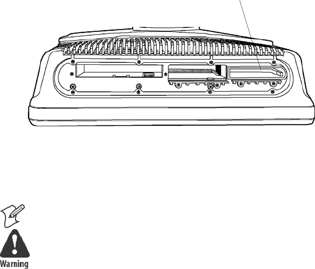
Card/Drive Slot
RemovetheradomecovertoaccessthePCMCIAcard/driveslot.When
reinstalling the cover, carefully route the antenna cables near the slot to
avoid damage.
PC Card Slot (PCMCIA)
PCMCIA Slot
CV60 Top View (Radome Cover Removed)
This user-accessible slot is for PC Card devices. The 68-pin slot can
accommodate a Type I or Type II device.
Note: Use spinning media for fixed-mount applications only.
Warning: Both edges of PC cards must be in the correct grooves in the
drivetoavoiddamagetothecardortothecomputer.DoNOTforce
PC cards into their respective slots.
Introduction
—Chapter 1
9CV60 Vehicle-Mount Computer User’s Manual
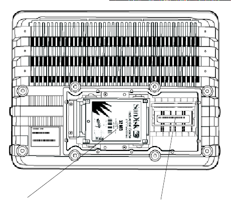
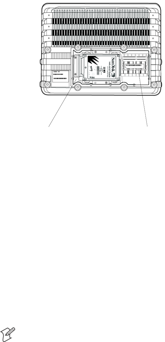
Hard Drive/Memory Location
Remove the rear cover to access the hard drive/memory slot. When rein-
stalling the cover, take care not to drop screws or other metallic objects
into the compartment.
Hard Drive Location
This user-accessible compartment is for the hard drive, mounting bracket
and SODIMM memory slot.
Hard drive and bracket SODIMM Memory Slot
SODIMM Memory Slot
The SODIMM slot (Single Outline Dual Inline Memory Module) allows
upgrading the base memory from 128MB to 384MB with an Intermec
approved SDRAM card.
IntroductionChapter —1
10 CV60 Vehicle-Mount Computer User’s Manual
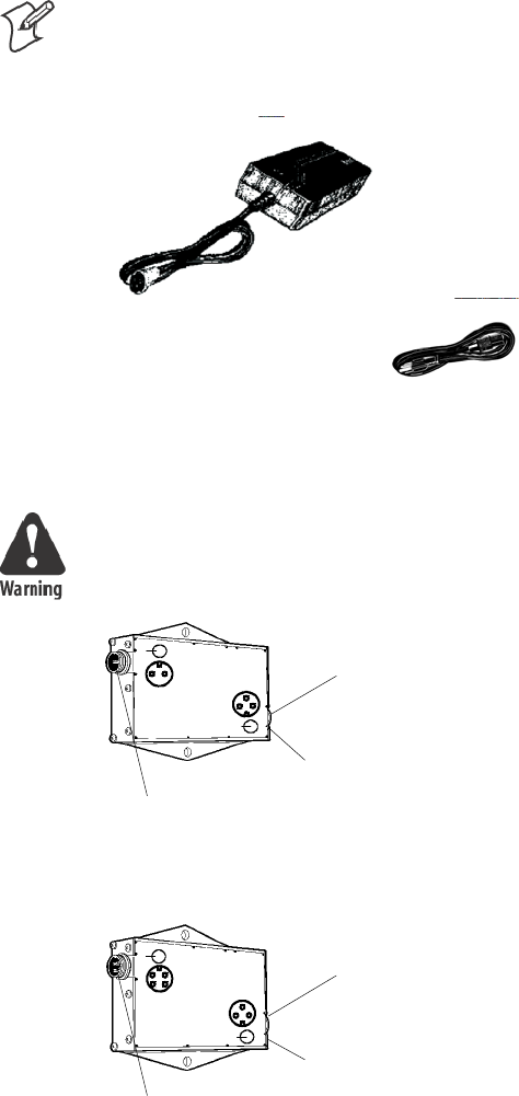
AC-DC Power Supply
Note: The AC power supply shown below does NOT have an On/Off
switch. To disable power to a fixed-mount CV60, use the On/Off switch
on the computer itself or unplug the AC power cable from the wall outlet.
A
C
P
owe
r
Su
p
p
l
y
w
i
th
U
.S
P
owe
r
C
o
r
d
DC-DC Power Supplies
Warning: Make sure you have the correct power converter for your
application. See Specifications for input voltage ranges.
””
””
Green LED
Power Output
Indicator
Input
Connector
P/N 851-041-001
Output
Connector
Green LED
Power Output
Indicator
Input
Connector
P/N 851-040-001
Output
Connector
””
””

Introduction
—Chapter 1
11CV60 Vehicle-Mount Computer User’s Manual
Maintenance
Your terminal requires very little maintenance. Clean the terminal and the
display periodically, and perform the daily checks listed below. If a failure
message appears on the display, the computer may need to be sent to an
authorized service facility for repair or adjustment.
Cleaning
A recommended cleaner for the exterior of the CV60 Vehicle-Mount
Computer display is MICRO-CLEAN II Cleaner, made by Foresight In-
ternational, Inc., 4887 F Street, Omaha, Nebraska 68127-0205 (phone:
1-800-637-1344).
Caution: Do not pour any cleaner directly on the display.
Caution: Do NOT use a water-based cleaner on the display.
Caution: Use ethanol-based cleaners ONLY on the display.
Note: Keep the display area clean and free of dust, dirt, grime, or smudges.
Failure to do so can result in unreliable touch entries. Use a soft, lint-free
cloth dampened with ethanol alcohol to remove dirt or finger smudges
from the display area.
Daily Checks
Each work day you should check to make sure that:
SAll mounting knobs are tight.
SThe power cable is secure.
SThe scanner cable is secure.
SThe keyboard cable is secure.
IntroductionChapter —1
12 CV60 Vehicle-Mount Computer User’s Manual
Specifications
CV60 Vehicle-Mount Computer
Physical/Environmental
SWeight: 5.0 kg (11.02 lbs) for base unit
Size
SHeight: 26 cm (9.44 in)
SWidth: 34 cm (13.38 in)
SDepth: 9.5 cm (3.74 in)
Environmental
SRecommended Operating Temperature Range (Solid State Drive):
–20° C to 50° C (–4° to 122° F)
SRecommended Operating Temperature Range (Rotating Drive): 0° C
to 50° C (32° to 122° F)
SRecommended Operating Temperature Range (Heater Option): –30°
C to 50° C (–22° to 122° F)
SRecommended Storage Temperature Range: -30° C to 70° C (–22° to
158° F)
Processor/Memory/Storage
SIntel P-III 800Mhz embedded processor
S128MB base memory with upgrade to 384MB SDRAM
S512KB FLASH.
SRemovable IDE rotating media or solid state drive or PC Card solid
state memory
SResistive display/touch Screen
S12.1 Inch, Color TFT 800 X 600 SVGA
System Software
SWindows XP, Embedded
SWindows XP Professional
SWindows CE.NET
Introduction
—Chapter 1
13CV60 Vehicle-Mount Computer User’s Manual
Power System
S6-36 VDC DC/DC converter for 12 V vehicle systems
S15-96 VDC DC/DC converter for 24-72 V vehicle systems
STypical current consumption -
SAC/DC adapter that supports international power requirements
SOptional Uninterruptible Power Supply
Wired Connectivity
STwo RS-232 ports, supporting external tethered scanners
S2USBhostports
S10BaseT/100BaseT Ethernet
Wireless Connectivity
S802.11g
SEmbedded wireless scanning option
SWireless Printing radio module
Peripherals/Accessories
SExternal alpha/numeric keyboard, PS/2
STethered barcode scanners
SMounting brackets to meet a wide range of vehicles.
Intermec Scanners:
Sabre (1551, 1552, 1553)
Vista (1400, 1800)
External Keyboards
PS/2 interface with locking connector.
External mouse
Off-the-shelf USB mouse.
IntroductionChapter —1
14 CV60 Vehicle-Mount Computer User’s Manual
FCC Notice
The user(s) of this product are cautioned to use accessories and peripherals
approved by Intermec Technologies Corporation. The use of accessories
other than those recommended, or changes to this product that are not
approved by Intermec Technologies Corporation, may void the compliance
of this product and may result in the loss of the users authority to operate
the equipment.
This device complies with Part 15 of the FCC Rules. Operation is subject
to the following two conditions: (1) this device may not cause harmful in-
terference, and (2) this device must accept any interference received, in-
cluding interference that may cause undesired operation.
FCC regulations limit exposure to radio frequency (RF) radiation. To
comply with these regulations, operators of this device and nearby persons
must maintain a distance of at least 20 cm. (8 inches) from the antenna
assembly.Whilethedeviceison,theoperator’sbodyandpartsofthebody
such as eyes, hands, or head, must be 20 cm. (8 inches) or farther from the
antenna assembly.

15CV60 Vehicle-Mount Computer User's Manual
Operation
2
This chapter tells you how to prepare the computer for first time operaĆ
tion and includes instructions for attaching or installing certain options
or peripheral equipment. Once the computer has successfully booted to
the operating system, you may need to load an application program or
data.

OperationChapter —2
16 CV60 Vehicle-Mount Computer User's Manual
Startup Requirements
Before powering up the computer for the first time, be sure it is securely
mounted, that all cable connections are secure, and that the DC power inĆ
put cable is firmly attached.
The computer begins its boot (start up) sequence when power is supplied
to the DC power input connector and the On/Off switch is ON (press the
switch briefly).
In the case of an AC-powered (fixed-mount) computer, the power supply
must be connected to the computer and plugged into a wall outlet.
Vehicle mounts require that the DC-DC power converter be properly conĆ
nected to the vehicle batteries and to the computer.
CV60 Vehicle-Mount Computer
Startup Sequence
Your computer should start up after all connections have been made, power
has been applied, and the On/Off switch has been pressed.
During startup, the computer (1) performs a power-on self-test, (2) runs
the hardware initialization program, and (3) boots the operating system.
Once the computer boots" (starts up) successfully, you may load additionĆ
al application software if this has not already been done for you. If you
install a radio or other optional device, you may have to install driver softĆ
ware or make new system setups for the device(s) to work properly.
Operation—Chapter 2
17CV60 Vehicle-Mount Computer User's Manual
Options
The CV60 can accommodate a 2.5 inch hard drive (or a solid state drive)
plus one PC card. The instructions and illustrations that follow will help
you perform these installations if they have not already been done.
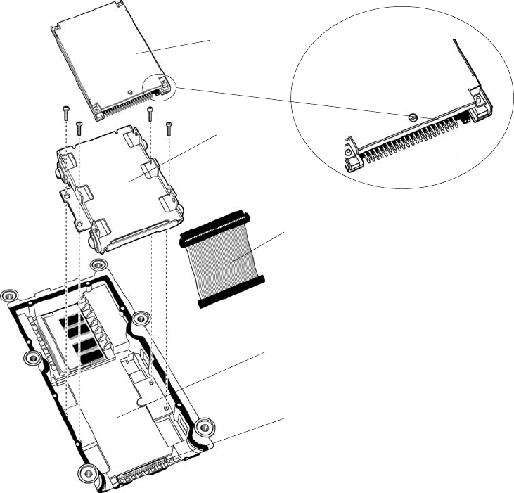
Hard Drive Installation
Attach the media drive to the bracket before use. Refer to the accompanyĆ
ing illustrations and the instructions to attach the bracket to your drive.
Bracket
Ribbon Cable
Drive Bay
Drive Bay Connector
Drive
Pin 1
1Insert the ribbon cable through the bracket.
2Connect the ribbon cable to the drive, noting pin 1 position.
3Align the connector-end of the drive and the bracket.
4Use four screws to secure the drive to the bracket.
5Connect the ribbon cable to the drive bay connector.
6Use an additional four screws to secure the bracket to the drive bay.
OperationChapter —2
18 CV60 Vehicle-Mount Computer User's Manual
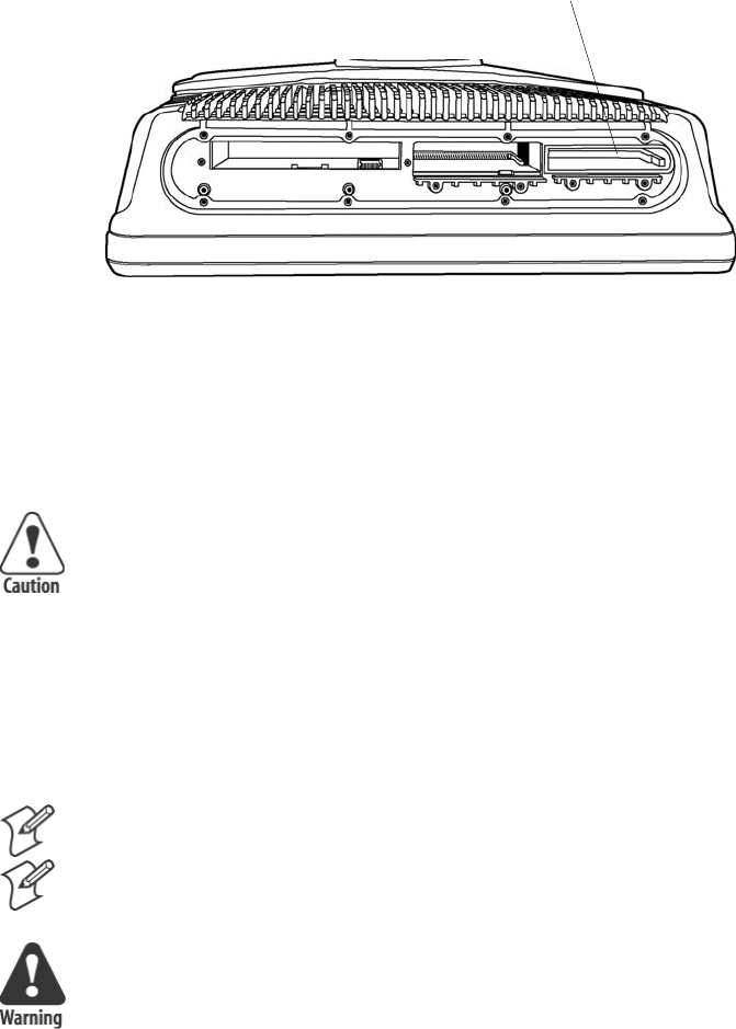
Solid State Drive Installation
A bracket is also required to install a solid state drive. Installation is the
same as on the previous page. If your computer is set up so that a solid
state drive will be the boot disk, then it requires a jumper. If your computĆ
er will boot from some other source, the solid state media drive must be
jumpered.
IDE Drive Bay SODIMM Slot
CV60 Rear View (Mounting Bracket Removed
1If the solid state media is not the boot drive, install the jumper as
shown.
2Place the solid state media drive in the bracket as shown.
3Align the connector-end of the drive and the bracket.
4Use four screws to secure the drive.
5Connect the ribbon cable to the drive bay connector.
6Use an additional four screws to secure the bracket to the drive bay.
SODIMM Slot
Your CV60 contains 128MB of base memory. You can upgrade the
memory to 384MB maximum via the SODIMM (Single Outline Dual
Inline Memory Module) slot depending on the operating system.
Consult your Intermec Sales Representative about the memory options
available for your device.
Note: Use of unapproved SODIMM modules may void your warranty.
Operation—Chapter 2
19CV60 Vehicle-Mount Computer User's Manual
Card/Drive Slot
PC Card Installation
The PC Card drive (slot") is located on the top of the computer. Use a
Phillips screwdriver to remove the radome cover to access the PC card slot.
PC Card Slot
To install a PC Card, follow these steps:
1Remove the radome cover.
2Hold the PC Card with the connector facing into the computer.
Caution: Do NOT force a PC card into its slot.
3Slide the PC Card into the slot.
4If you encounter resistance, you may need to flip the card over and reĆ
peat Step 3. The card is fully seated when the card ejector is extended.
5Use Program Manager to check the Card View icon. It will identify
which slot contains a PC Card. PC Cards are identified as drive D:\ or
E:\.
6Reinstall the radome cover.
Note: Use spinning-media for fixed-mount applications only.
Note: The Windows CE OS option uses a PC card. It does not install in
the IDE Drive Bay.
Warning: Both edges of PC cards must be in the correct grooves in the
drive to avoid damage to the card or to the computer. Do NOT force
PC cards or the IDE drive into their respective slots.
OperationChapter —2
20 CV60 Vehicle-Mount Computer User's Manual
Radio Installation Options
Your CV60 Vehicle-Mount Computer is configured for radio options at the
factory.
802.11 Radio
The 802.11 radio is a factoryĆinstalled option. The operating system autoĆ
matically installs and configures the drivers for use.
Wireless Printing Radio Module
The Wireless Printing radio module is factoryĆinstalled. The operating
system automatically installs and configures the drivers for use.
Antenna Mount
Radome Cover
Operation—Chapter 2
21CV60 Vehicle-Mount Computer User's Manual
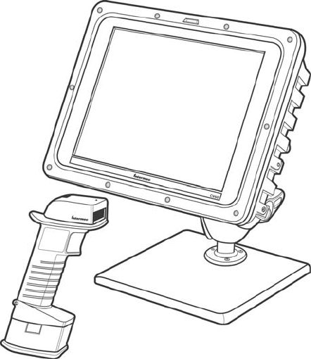
PicoLinkt Radio
Intermec's PicoLink radio uses an unlicensed 2.4 GHz radio frequency
(RF) hopping design that has global regulatory acceptance and interference
immunity to other narrow band RF sources.
The Sabret1552 wireless scanner connects by associating" to the CV60
via wireless link for identification.
Setting up the Cordless Scanner
Fully charge the cordless scanner battery before using the scanner.
Refer to the user documentation included with your cordless scanner for
more information.
Scan the barcode located on the side of the CV60 to associate the scanner
with its data collection device.
CV60 with Sabre 1552 Cordless Scanner
OperationChapter —2
22 CV60 Vehicle-Mount Computer User's Manual
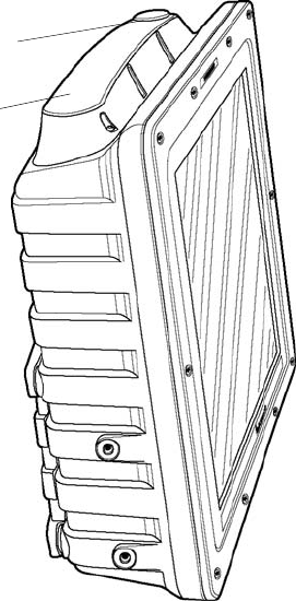
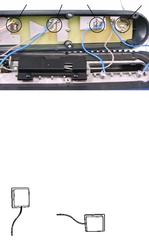
External Antenna Connection
The external antenna mounts on the radome assembly" on the top of the
computer. Refer to the illustration below for connection information.
802.11 External
Antenna
Connector
Picolink Antenna
Connector
802.11 Antenna
Connector
Patch Antenna
The 2.4 GHz patch" antenna can be mounted on a wall using either
screws or small patches of adhesive-backed hook and loop fastener material.
Since system performance and antenna polarization are site-dependent, a
permanent mounting location and orientation may require some experĆ
imentation. In most fixed installations the antenna should be mounted iniĆ
tially in a vertically polarized position, with the cable from the antenna parĆ
allel to the floor/ceiling.
Horizontal Polarization Vertical Polarization
In mobile installations, best performance will be achieved by mounting the
antenna flat, on top of the operator safety cage. Use at least two screws to
hold the antenna in place.

Operation—Chapter 2
23CV60 Vehicle-Mount Computer User's Manual
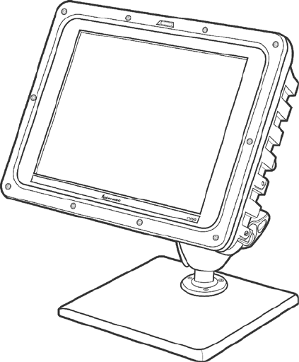
Desktop Mounting Options
This computer can be used as a stationary computer on a desktop or other
work surface. An optional weighted baseplate and adjustable twin-ball pedesĆ
tal are available, as shown below.
An AC power supply is required to power the computer for desktop use.
Desktop Mount
Removing PC Cards
The CV60 allows the use of one PCMCIA Type II PC Card. Instructions for
installing PC cards are provided earlier in this chapter.
To remove a PC Card, follow these steps:
1Remove the radome cover.
2Press inward on the ejector to release the PC Card.
3Grasp the edge of the card to remove it.
4Reinstall the radome cover that you removed in Step 1.
Start-Up
All options and accessories must be connected or installed, and the power
supply connected to the computer. It will start up (boot") to a factory-
configured operating system when you move the On/Off switch to the
ON position. If the computer does not, it may be necessary to install an
operating system or application software.
Factory-configured operating systems currently available:
SWindows XP Professional
SWindows XP embedded
SWindows CE.NET

OperationChapter —2
24 CV60 Vehicle-Mount Computer User's Manual
Restart (or, Reboot")
Note: Make sure that a keyboard is attached to the CV60 BEFORE atĆ
tempting to perform a warm restart.
If the system locks up during normal operations, you can reset it by perĆ
forming either a warm" or a cold" restart. Use the warm restart to clear
the system memory to run another program but not perform a self-test.
When a warm restart does not restore operation, perform a cold restart.
Warm Restart
If your operating system is Windows CE, exit the current application, then
do the following to perform a warm restart:
1Press Ctrl+Alt+Del on the keyboard to restart
2Load, or reload, the desired software application.
3Resume normal operation.
4If your operating system is Windows XP, select Start > Shut Down
from the Windows desktop, then select Restart to perform a restart or
tap Restart on the display.
Cold Restart
Perform a proper system shutdown, then toggle the On/Off switch on the
bottom of the computer to the Off position. Wait one second, then toggle
the switch back to the On position. If the On/Off switch is inaccessible,
then do one of the following: For fixed-mount units, unplug the AC power
supply from the wall outlet for a few seconds. Be sure to plug it back in.
For vehicle-mounted units, interrupt power to the DC/DC power convertĆ
er for a few seconds.
Operation—Chapter 2
25CV60 Vehicle-Mount Computer User's Manual
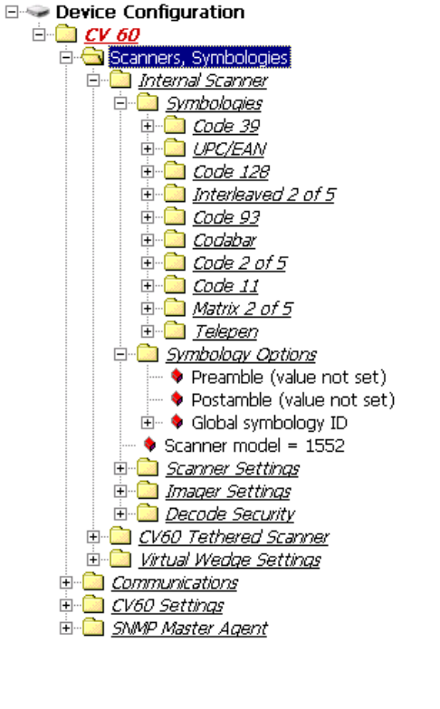
Setting up for Data Collection
Device Configuration
Scanner settings for the CV60 Vehicle-Mount Computer can be configured
via the Intermec Settings control panel applet. From the CV60 Vehicle-
Mount Computer, tap Start > Settings > Control Panel > Intermec SetĆ
tings.
The Intermec Settings utility creates the schema and map files used for the
Device Configuration tree.
For more information, see the Intermec SDK User's Manual and CV60 XP
SDK User's Manual.
The SDK is part of the Intermec Developer's Library (IDL) and is availĆ
able on CD (P/N 235-114-001) or as a download from the Intermec web
site at www.intermec.com.
OperationChapter —2
26 CV60 Vehicle-Mount Computer User's Manual

27CV60 Vehicle-Mount Computer User's Manual
PhoenixBIOS Setup Utility
3
A PS/2Ćcompatible keyboard is required to configure the PhoenixBIOS
Setup Utility (PSU). Turn off the CV60 Vehicle-Mount Computer before
attaching the keyboard, if one is not attached already.
Reboot the CV60. Be ready to press the [F2] keys when the following
prompt appears on the bottom, left side of the Intermec screen:
Press F2 for System Utilities
When you see this prompt, you have approximately eight seconds to press
the [F2] key to enter the PSU, otherwise the computer proceeds to boot
up.
Note: Any changes made to the PSU are not effective until they are saved
and the CV60 is rebooted. Select Exit > Exit Saving Changes to save the
changes.
Press <Esc> to exit any window without changes.
PhoenixBIOS Setup UtilityChapter —3
28 CV60 Vehicle-Mount Computer User's Manual
General Information
This page contains the same information as given in the General Help,
available when you press [F1].
Setup changes system behavior by modifying the BIOS configuration. SeĆ
lecting incorrect values may cause system boot failure, if so, then press [F9]
to load setup default values to recover the system.
SPress the up or down arrow keys < ↑↓ > to select fields in the current
menu.
SPress the <Page Up> or <Page Down> keys to move to the previous or
next page of scrollable menus.
SPress the <Home> or <End> keys to move to the top or bottom item of
the current menu.
SWithin a field, press [F5} or < ć > (dash) to decrease the value, or press
[F6} or < + > (plus symbol) to increase the value.
SPress the left or right arrow keys < ← / → > to move between menus.
SPress <Enter> to display more options for items marked with ".
SPress [F9] to load factoryĆinstalled Setup Default values.
SPress [F10] to save the current settings and exit the PSU.
SPress either <Esc> or <Alt> [X] to exit the Setup or to return to the preĆ
vious menu.
SPress [F1] or <Alt> [H] to display General Help information. Press [F1]
or <Enter> to close the General Help screen.

PhoenixBIOS Setup Utility—Chapter 3
29CV60 Vehicle-Mount Computer User's Manual
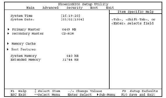
Main
Use this menu to adjust the PC's date and time, primary and secondary
masters, set the state of the memory cache, select boot features, and view
the system memory and extended memory values. Press the up or down
arrow keys < ↑↓ > to move the cursor between fields. Press the left or right
arrow keys < ←/→ > to move the cursor to another menu.
System Time
System Time is of the military hour, minute, and second format.
Press <Tab> or <Enter> to move the cursor to the right, <Shift><Tab> to
move the cursor to the left. Enter the correct number, then move the curĆ
sor to the next field. The system does not recognize characters other than
numbers, and only recognizes the following values:
SHour: 0ć23
SMinute: 0ć59
SSecond: 0ć59
Note: If you have entered an incorrect number, move the cursor off the
field, then back on, to enter the correct number,
System Date
System Date is of the month, day, and year format.
Press <Tab> or <Enter> to move the cursor to the right, <Shift><Tab> to
move the cursor to the left. Enter the correct number, then move the curĆ
sor to the next field. The system does not recognize characters other than
numbers, and only recognizes the following values:
SMonth: 1ć12
SDay: 1ć31
SYear: 1981ć2099 (defaults to 1981 if entry was not valid)
Note: If you have entered an incorrect number, move the cursor off the
field, then back on, to enter the correct number,
PhoenixBIOS Setup UtilityChapter —3
30 CV60 Vehicle-Mount Computer User's Manual
Primary Master
Press [Enter] to access the Primary Master menu. Press [Esc] to return to
the Main menu.
At the Type field, press the plus (+) or minus (-) key to change the value to
one of the following. The value selected dictates what configurable inforĆ
mation is presented. Default is None.
Auto
Select this to automatically set the hardĆdisk drive installed. Press the up or
down arrow keys < ↑↓ > to move the cursor to the following field:
S32 Bit I/O: Press the plus (+) or minus (-) key to enable or disable
32Ćbit IDE data transfers. Default is disabled.
None
Select this if there is no hardĆdisk drive.
CDĆROM
This indicates that a CDĆROM drive is the drive installed. Press the up or
down arrow keys < ↑↓ > to move the cursor between the following fields:
SMultiĆSector Transfers: Press the plus (+) or minus (-) key to select beĆ
tween 2, 4, 8, or 16 sectors per block for multiple sector transfers or to
disable the transfer. Default is disabled.
SLBA Mode Control: Press the plus (+) or minus (-) key to enable or
disable the use of the Logical Block Addressing (LBA) in place of cylinĆ
ders, heads, and sectors. Default is disabled.
S32 Bit I/O Press the plus (+) or minus (-) key to enable or disable 32Ćbit
IDE data transfers. Default is disabled.
STransfer Mode: Press the plus (+) or minus (-) key to select between
seven methods by which to move data to and from the drive. Default is
Standard.
SUltra DMA Mode: Press the plus (+) or minus (-) key to select between
six ultra DMA modes by which to move data to and from the drive or
to disable the movement. Default is Disabled.
IDE Removable
This indicates the removable disk drive is installed in the IDE sector. Press
the up or down arrow keys < ↑↓ > to move the cursor between the followĆ
ing fields:
SMultiĆSector Transfers: Press the plus (+) or minus (-) key to select beĆ
tween 2, 4, 8, or 16 sectors per block for multiple sector transfers or to
disable the transfer. Default is disabled.
SLBA Mode Control: Press the plus (+) or minus (-) key to enable or
disable the use of the Logical Block Addressing (LBA) in place of cylinĆ
ders, heads, and sectors. Default is disabled.
S32 Bit I/O Press the plus (+) or minus (-) key to enable or disable 32Ćbit
IDE data transfers. Default is disabled.
PhoenixBIOS Setup Utility—Chapter 3
31CV60 Vehicle-Mount Computer User's Manual
STransfer Mode: Press the plus (+) or minus (-) key to select between
seven methods by which to move data to and from the drive. Default is
Standard.
SUltra DMA Mode: Press the plus (+) or minus (-) key to select between
six ultra DMA modes by which to move data to and from the drive or
to disable the movement. Default is Disabled.
ATAPI Removable
This indicates the removable disk drive is installed in the ATAPI sector.
Press the up or down arrow keys < ↑↓ > to move the cursor between the
following fields:
SMultiĆSector Transfers: Press the plus (+) or minus (-) key to select beĆ
tween 2, 4, 8, or 16 sectors per block for multiple sector transfers or to
disable the transfer. Default is disabled.
SLBA Mode Control: Press the plus (+) or minus (-) key to enable or
disable the use of the Logical Block Addressing (LBA) in place of cylinĆ
ders, heads, and sectors. Default is disabled.
S32 Bit I/O Press the plus (+) or minus (-) key to enable or disable 32Ćbit
IDE data transfers. Default is disabled.
STransfer Mode: Press the plus (+) or minus (-) key to select between
seven methods by which to move data to and from the drive. Default is
Standard.
SUltra DMA Mode: Press the plus (+) or minus (-) key to select between
six ultra DMA modes by which to move data to and from the drive or
to disable the movement. Default is Disabled.
Other ATAPI
This indicates the disk drive is installed in an ATAPI sector other than the
removable sector. Press the up or down arrow keys < ↑↓ > to move the
cursor between the following fields:
SMultiĆSector Transfers: Press the plus (+) or minus (-) key to select beĆ
tween 2, 4, 8, or 16 sectors per block for multiple sector transfers or to
disable the transfer. Default is disabled.
SLBA Mode Control: Press the plus (+) or minus (-) key to enable or
disable the use of the Logical Block Addressing (LBA) in place of cylinĆ
ders, heads, and sectors. Default is disabled.
S32 Bit I/O Press the plus (+) or minus (-) key to enable or disable 32Ćbit
IDE data transfers. Default is disabled.
STransfer Mode: Press the plus (+) or minus (-) key to select between
seven methods by which to move data to and from the drive. Default is
Standard.
SUltra DMA Mode: Press the plus (+) or minus (-) key to select between
six ultra DMA modes by which to move data to and from the drive or
to disable the movement. Default is Disabled.
PhoenixBIOS Setup UtilityChapter —3
32 CV60 Vehicle-Mount Computer User's Manual
User
Enter the parameters of the hardĆdisk drive installed at this connection.
Press the up or down arrow keys < ↑↓ > to move the cursor between the
following fields:
SCylinders: Enter the number of cylinders involved in this capacity,
range is 0 through 65535. Default is 0.
SHeads: Enter the number of heads involved in this capacity, range is 1
through 16. Default is 1.
SSectors: Enter the number of sectors involved in this capacity, range is 0
through 63. Default is 0.
SMultiĆSector Transfers: Press the plus (+) or minus (-) key to select beĆ
tween 2, 4, 8, or 16 sectors per block for multiple sector transfers or to
disable the transfer. Default is disabled.
SLBA Mode Control: Press the plus (+) or minus (-) key to enable or
disable the use of the Logical Block Addressing (LBA) in place of cylinĆ
ders, heads, and sectors. Default is disabled.
S32 Bit I/O Press the plus (+) or minus (-) key to enable or disable 32Ćbit
IDE data transfers. Default is disabled.
STransfer Mode: Press the plus (+) or minus (-) key to select between
seven methods by which to move data to and from the drive. Default is
Standard.
SUltra DMA Mode: Press the plus (+) or minus (-) key to select between
six ultra DMA modes by which to move data to and from the drive or
to disable the movement. Default is Disabled.
Secondary Master
Press [Enter] to access the Secondary Master menu. Press [Esc] to return
to the Main menu.
At the Type field, press the plus (+) or minus (-) key to change the value to
one of the following. The value selected dictates what configurable inforĆ
mation is presented. Default is SanDisk SDP3B-85.
Auto
Select this to automatically set the hardĆdisk drive installed. Press the up or
down arrow keys < ↑↓ > to move the cursor to the following field:
S32 Bit I/O: Press the plus (+) or minus (-) key to enable or disable
32Ćbit IDE data transfers. Default is disabled.
None
Select this if there is no hardĆdisk drive.
CDĆROM
This indicates that a CDĆROM drive is the drive installed. Press the up or
down arrow keys < ↑↓ > to move the cursor between the following fields:
SMultiĆSector Transfers: Press the plus (+) or minus (-) key to select beĆ
tween 2, 4, 8, or 16 sectors per block for multiple sector transfers or to
disable the transfer. Default is disabled.
PhoenixBIOS Setup Utility—Chapter 3
33CV60 Vehicle-Mount Computer User's Manual
SLBA Mode Control: Press the plus (+) or minus (-) key to enable or
disable the use of the Logical Block Addressing (LBA) in place of cylinĆ
ders, heads, and sectors. Default is disabled.
S32 Bit I/O Press the plus (+) or minus (-) key to enable or disable 32Ćbit
IDE data transfers. Default is disabled.
STransfer Mode: Press the plus (+) or minus (-) key to select between
seven methods by which to move data to and from the drive. Default is
Standard.
SUltra DMA Mode: Press the plus (+) or minus (-) key to select between
six ultra DMA modes by which to move data to and from the drive or
to disable the movement. Default is Disabled.
IDE Removable
This indicates the removable disk drive is installed in the IDE sector. Press
the up or down arrow keys < ↑↓ > to move the cursor between the followĆ
ing fields:
SMultiĆSector Transfers: Press the plus (+) or minus (-) key to select beĆ
tween 2, 4, 8, or 16 sectors per block for multiple sector transfers or to
disable the transfer. Default is disabled.
SLBA Mode Control: Press the plus (+) or minus (-) key to enable or
disable the use of the Logical Block Addressing (LBA) in place of cylinĆ
ders, heads, and sectors. Default is disabled.
S32 Bit I/O Press the plus (+) or minus (-) key to enable or disable 32Ćbit
IDE data transfers. Default is disabled.
STransfer Mode: Press the plus (+) or minus (-) key to select between
seven methods by which to move data to and from the drive. Default is
Standard.
SUltra DMA Mode: Press the plus (+) or minus (-) key to select between
six ultra DMA modes by which to move data to and from the drive or
to disable the movement. Default is Disabled.
ATAPI Removable
This indicates the removable disk drive is installed in the ATAPI sector.
Press the up or down arrow keys < ↑↓ > to move the cursor between the
following fields:
SMultiĆSector Transfers: Press the plus (+) or minus (-) key to select beĆ
tween 2, 4, 8, or 16 sectors per block for multiple sector transfers or to
disable the transfer. Default is disabled.
SLBA Mode Control: Press the plus (+) or minus (-) key to enable or
disable the use of the Logical Block Addressing (LBA) in place of cylinĆ
ders, heads, and sectors. Default is disabled.
S32 Bit I/O Press the plus (+) or minus (-) key to enable or disable 32Ćbit
IDE data transfers. Default is disabled.
STransfer Mode: Press the plus (+) or minus (-) key to select between
seven methods by which to move data to and from the drive. Default is
Standard.
PhoenixBIOS Setup UtilityChapter —3
34 CV60 Vehicle-Mount Computer User's Manual
SUltra DMA Mode: Press the plus (+) or minus (-) key to select between
six ultra DMA modes by which to move data to and from the drive or
to disable the movement. Default is Disabled.
Other ATAPI
This indicates the disk drive is installed in an ATAPI sector other than the
removable sector. Press the up or down arrow keys < ↑↓ > to move the
cursor between the following fields:
SMultiĆSector Transfers: Press the plus (+) or minus (-) key to select beĆ
tween 2, 4, 8, or 16 sectors per block for multiple sector transfers or to
disable the transfer. Default is disabled.
SLBA Mode Control: Press the plus (+) or minus (-) key to enable or
disable the use of the Logical Block Addressing (LBA) in place of cylinĆ
ders, heads, and sectors. Default is disabled.
S32 Bit I/O Press the plus (+) or minus (-) key to enable or disable 32Ćbit
IDE data transfers. Default is disabled.
STransfer Mode: Press the plus (+) or minus (-) key to select between
seven methods by which to move data to and from the drive. Default is
Standard.
SUltra DMA Mode: Press the plus (+) or minus (-) key to select between
six ultra DMA modes by which to move data to and from the drive or
to disable the movement. Default is Disabled.
User
Enter the parameters of the hardĆdisk drive installed at this connection.
Press the up or down arrow keys < ↑↓ > to move the cursor between the
following fields:
SCylinders: Enter the number of cylinders involved in this capacity,
range is 0 through 65535. Default is 650.
SHeads: Enter the number of heads involved in this capacity, range is 1
through 16. Default is 8.
SSectors: Enter the number of sectors involved in this capacity, range is 0
through 63. Default is 32.
SMultiĆSector Transfers: Press the plus (+) or minus (-) key to select beĆ
tween 2, 4, 8, or 16 sectors per block for multiple sector transfers or to
disable the transfer. Default is disabled.
SLBA Mode Control: Press the plus (+) or minus (-) key to enable or
disable the use of the Logical Block Addressing (LBA) in place of cylinĆ
ders, heads, and sectors. Default is disabled.
S32 Bit I/O Press the plus (+) or minus (-) key to enable or disable 32Ćbit
IDE data transfers. Default is disabled.
STransfer Mode: Press the plus (+) or minus (-) key to select between
seven methods by which to move data to and from the drive. Default is
Standard.
SUltra DMA Mode: Press the plus (+) or minus (-) key to select between
six ultra DMA modes by which to move data to and from the drive or
to disable the movement. Default is Disabled.
PhoenixBIOS Setup Utility—Chapter 3
35CV60 Vehicle-Mount Computer User's Manual
Memory Cache
Press [Enter] to access the Memory Cache menu and set the state of the
memory cache. Press [Esc] to return to the Main menu.
Memory Cache
Press the plus (+) or minus (-) key to enable or disable the memory cache.
Default is enabled.
Cache System/Video BIOS Areas
Press the plus (+) or minus (-) key to select either Write Protect" or unĆ
cached" to control the caching of the system BIOS area. Default is Write
Protect
Cache Base 0ć512k, 512kć640k, Extended Memory Area
Press the plus (+) or minus (-) key to select Write Back," uncached,"
Write Through," or Write Protect" to control the caching of the 512k or
512k through 640k base memory or extended memory area. Default is
Write Back.
Cache A000ćAFFF, B000ćBFFF
Press the plus (+) or minus (-) key to select Disabled," USWC Caching,"
Write Through," Write Protect," or Write Back" to control the apĆ
propriate cache range. Default is Disabled.
Cache C800ćCBFF through EC00ćEFFF
Press the plus (+) or minus (-) key to select Disabled," Write Through,"
Write Protect," or Write Back" to control the appropriate cache range.
Default is Disabled.
Boot Features
Press [Enter] to access the Boot Features menu and configure the floppy
check, the summary screen, the bootĆtime diagnostic screen, or the QuickĆ
Boot mode. Press [Esc] to return to the Main menu.
Summary Screen
Press the plus (+) or minus (-) key to dictate whether to display system
configuration information on boot. Default is enabled.
BootĆTime Diagnostic Screen
Press the plus (+) or minus (-) key to state whether to display the diagnosĆ
tic screen during the boot up process. Default is disabled.
QuickBoot Mode
Press the plus (+) or minus (-) key to dictate whether the system can skip
certain tests during the boot process, thus shortening the time required to
perform the boot. Default is enabled.

PhoenixBIOS Setup UtilityChapter —3
36 CV60 Vehicle-Mount Computer User's Manual
Advanced
This configures advanced features within your CV60. Press the up or
down arrow keys < ↑↓ > to move the cursor to the following fields. Press
the left or right arrow keys < ←/→ > to move the cursor to another
menu.
Caution: If you set items in this menu to incorrect values, you could
cause your system to malfunction.
Advanced Chipset Control
Press [Enter] to access the Advanced Chipset Control menu and configure
the video boot type, the enable memory gap, or the frequency ratio. Press
[Esc] to return to the Advanced menu.
Video Boot Type
Press the plus (+) or minus (-) key to select either 512 KB or 1 MB of sysĆ
tem memory to allocate to the onboard video controller. Default is 1 MB.
Enable Memory Gap
Press the plus (+) or minus (-) key to select either Disabled" or ExĆ
tended." If Extended," this turns off the system RAM to free space for use
with an option card. Default is disabled.
Frequency Ratio
Press the plus (+) or minus (-) key to select from fourteen different internal
frequency multiplier values of the CPU. Default is 4x.
I/O Device Configuration
Press [Enter] to access the Advanced Chipset Control menu and configure
peripheral devices, such as serial ports, panel heater circuit and power, or
the Picolink radio. Press [Esc] to return to the Advanced menu.
Serial Ports
Press the plus (+) or minus (-) key to select Disabled," Enabled," Auto,"
or OS Controlled" to configure serial ports A through D.
If Enabled" is selected, press the plus (+) or minus (-) key to set the base
I/O address and the interrupt for the enabled serial port. Default is OS
Controlled.
Note: To enable the touchscreen, select Enabled" for Windows CE sysĆ
tems and OS Controlled" for Windows XP systems.
Panel Heater
Press the plus (+) or minus (-) key to enable or disable the panel heater cirĆ
cuit and power. Default is disabled.
Picolink
Press the plus (+) or minus (-) key to enable or disable support for the PiĆ
colink radio. Default is disabled.
PhoenixBIOS Setup Utility—Chapter 3
37CV60 Vehicle-Mount Computer User's Manual
Legacy USB Support
Press the plus (+) or minus (-) key to enable or disable support for Legacy
Universal Serial Bus (USB) devices. Default is enabled.
Reset Configuration Data
Press the plus (+) or minus (-) key to select whether to clear the Extended
System Configuration Data (ESCD). Default is No.
FirstWare Authentication Level
Press the plus (+) or minus (-) key to select the level of FirstWare authentiĆ
cation, from high, medium, or low. Default is High.
PC Card Boot Support
Press the plus (+) or minus (-) key to dictate whether to support PC card
boot. Default is enabled.
PhoenixBIOS Setup UtilityChapter —3
38 CV60 Vehicle-Mount Computer User's Manual
Security
Use this menu to set the supervisor password. Press the up or down arrow
keys < ↑↓ > to move the cursor to the following field. Press the left or
right arrow keys < ←/→ > to move the cursor to another menu.
Set Supervisor Password
Press the plus (+) or minus (-) key to dictate how controlled is the superviĆ
sor password to the setup utility. Default is Enter.
PhoenixBIOS Setup Utility—Chapter 3
39CV60 Vehicle-Mount Computer User's Manual
Boot
Use this menu to view or configure devices for the dualĆbooting process
for Windows CE and XP systems. Press the plus (+) or minus (-) key to
rearrange the order of the devices listed. Press the up or down arrow keys <
↑↓ > to move the cursor between devices. Press the left or right arrow keys
< ←/→ > to move the cursor to another menu.
PhoenixBIOS Setup UtilityChapter —3
40 CV60 Vehicle-Mount Computer User's Manual
Exit
Use this menu to access exit options, settings, and version information.
Press the up or down arrow keys < ↑↓ > to move the cursor between deĆ
vices. Press the left or right arrow keys < ←/→ > to move the cursor to
another menu.
Exit Saving Changes
Select this option to exit the PSU and save your changes to CMOS. Press
[Enter] to select the option, then press [Yes] to continue. Press [No] to
return to the Exit menu.
Exit Discarding Changes
Select this option to exit the PSU without saving the data to CMOS. Press
[Enter] to select the option, then press [Yes] to continue. Press [No] to
return to the Exit menu.
Load Setup Defaults
Select this option to load the default values for all setup items. Press [EnĆ
ter] to select the option, then press [Yes] to continue. Press [No] to return
to the Exit menu.
Discard Changes
Select this option to discard all current changes and load previous values
from CMOS for all setup items. Press [Enter] to select the option, then
press [Yes] to continue. Press [No] to return to the Exit menu.
Save Changes
Select this option to save current changes to CMOS without exiting the
PSU. Press [Enter] to select the option, then press [Yes] to continue. Press
[No] to return to the Exit menu.
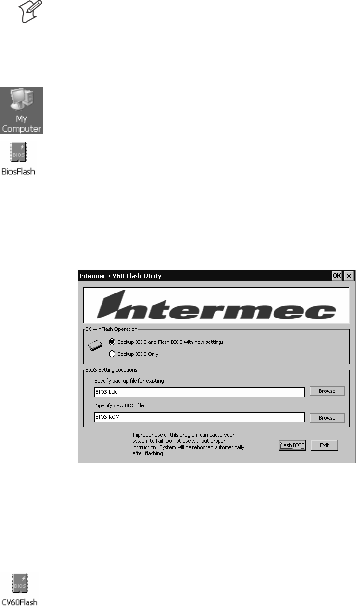
PhoenixBIOS Setup Utility—Chapter 3
41CV60 Vehicle-Mount Computer User's Manual
Reflash Procedure
Note: See the CV60 Recovery Instruction Guide P/N: 962Ć054Ć073 for
more information.
Windows CE
The following information pertains to the Windows CE operating system.
1Copy the new BIOS onto a storage card, insert the card into your
CV60, then reboot the unit.
2From the CV60 desktop, double-click the My Computer desktop icon,
then doubleĆclick the Windows folder.
3DoubleĆclick the BiosFlash desktop icon to access the Intermec CV60
Flash Utility.
4Select Backup BIOS and Flash BIOS with new settings, then from
within the BIOS Settings Locations box, click the second Browse to loĆ
cate the new BIOS ROM file. You may also click the first Browse to
dictate the location where to save the backup file.
Click Flash BIOS to initiate the reflash. The system should automatiĆ
cally reboot after finishing. If not, then perform a reboot.
5Upon reboot, at the DOS prompt, enter the following:
BiosFlash.exe/nogui/f:<newbiosname>.rom/b:<backupfilename>
where newbiosname is the name of your new flash file name and
backupfilename is the name of the backed up file.
Windows XP
This information pertains to the Windows XP and Windows XP EmĆ
bedded operating systems. Do the instructions as written for Windows CE,
except doubleĆclick the CV60Flash desktop icon.
PhoenixBIOS Setup UtilityChapter —3
42 CV60 Vehicle-Mount Computer User's Manual

43CV60 Vehicle-Mount Computer User's Manual
Windows Device
Configurations
4
This chapter has the following configurable devices for the Windows CE,
Windows XP, and Windows XP Embedded operating systems:
SCV60 Settings (page 44)
SNetwork Adapters (page 48)
SAutoIP/DHCP (page 140)
SStylus (page 67)
STCP/IP (page 72)
STethered Scanner (page 75)
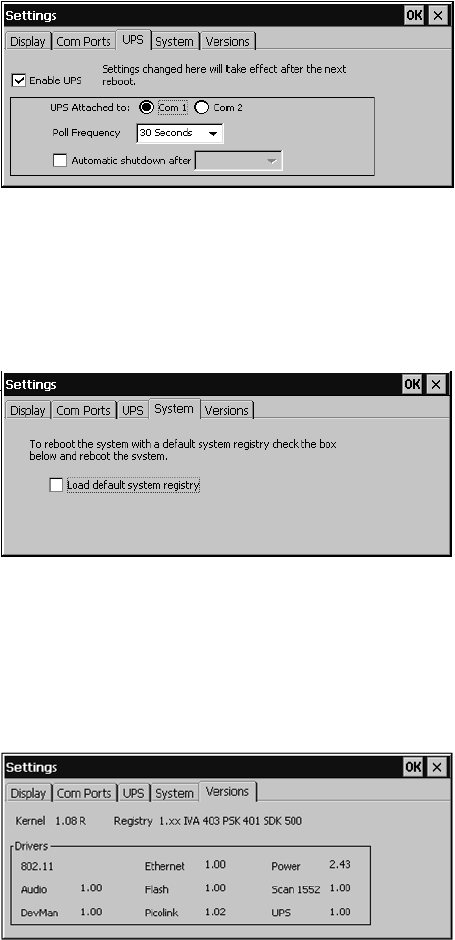
Windows Device ConfigurationsChapter —4
46 CV60 Data Collection PC User’s Guide
UPS
Use this page to dictate which COM port is to hold the UPS service, how
often to poll the UPS, and set when the unit is to automatically shut
down. Click the drop-down arrow to reset the Poll Frequency value.
Check Automatic shutdown before you click its drop-down arrow to ad-
just its value.
Be sure to check Enable UPS to enable the rest of the page.
System
Use this page to reboot the system with a default system registry. Check
Load default system registry then reboot the system.
Versions
Use this page to view the kernel, registry, IVA, PSK and SDK versions.
Current driver versions are displayed in the group box below.
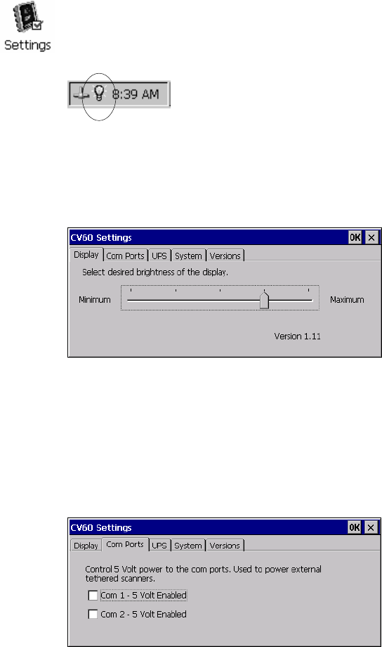
Windows Device ConfigurationsChapter —4
44 CV60 Vehicle-Mount Computer User's Manual
CV60 Settings
Use the CV60 control panel applet to adjust the brightness, communicaĆ
tion ports, and UPS of your CV60. Note that these can also be adjusted
within your PhoenixBIOS Setup Utility. See Chapter 3, PhoenixBIOS SetĆ
up Utility" for more information.
Windows CE
The following information pertains to the Windows CE operating system.
From the desktop, select Start > Settings > Control Panel, then doubleĆ
click the Settings desktop icon, or doubleĆclick the lightbulb icon in the
System Tray (circled in the following illustration). Make your adjustments,
then click OK to close the Settings.
Display
Use this page to adjust the brightness of your display. Tap the desired level
of display brightness within the Minimum/Maximum range.
Com Ports
Check Com 1 ć 5 Volt Enabled to activate the tethered scanner. If a PicoĆ
link radio is installed in your CV60, then Com 2 ć 5 Volt Enabled is
checked by default.
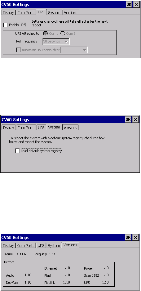
Windows Device Configurations—Chapter 4
45CV60 Vehicle-Mount Computer User's Manual
UPS
Use this page to set which COM port is to hold the UPS service, how
often to poll the UPS, and set the time when the unit is to automatically
shut down. Click the dropĆdown arrow to reset the Poll Frequency value.
Check Automatic shutdown before you click its drop-down arrow to adĆ
just its value.
Be sure to check Enable UPS to enable the rest of the page.
System
Use this page to reboot the system with a default system registry. Check
Load default system registry then reboot the system.
Versions
Use this page to view the kernel and registry versions.
Current driver versions are displayed in the group box below.
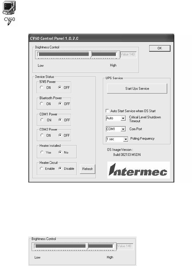
Windows Device ConfigurationsChapter —4
46 CV60 Vehicle-Mount Computer User's Manual
Windows XP
The following information pertains to the Windows XP and Windows XP
Embedded operating systems.
From the desktop, select Start > Settings > Control Panel, then doubleĆ
click the CV60 desktop icon. Do your adjustments, then click OK to close
the CV60 Control Panel.
Brightness Status
Within this box, tap the desired level of brightness within the Low/High
range.

Windows Device Configurations—Chapter 4
47CV60 Vehicle-Mount Computer User's Manual
Device Status
Use the information within this box to monitor whether power to the
9745, Bluetooth, COM1, or COM2 is on or off, the display heater is
installed, and the heater circuit is enabled.
UPS Service
Use this box to start up the UPS service and to set which COM port is to
hold the UPS service, how often to poll the UPS, and set when the unit is
to automatically shut down. Click the dropĆdown arrow to reset the apĆ
propriate values. Check Auto Start Service when OS Start before adjustĆ
ing any values.
Windows Device ConfigurationsChapter —4
48 CV60 Vehicle-Mount Computer User's Manual
Network Adapters
Your CV60 can have up to three radios installed. The default network
adapter or radio is dependent on what radios are installed in your CV60.
Below are the the network adapters that exist as of this publication. See the
Developer's Support web site for the latest information on network adaptĆ
ers for your unit.
S802.11b/g Radios (ActionTec) Ċ page 51.
SWireless Printing (Bluetooth) Ċ page 60.
SPicolink Ċ page 66.

Windows Device ConfigurationsChapter —4
50 CV60 Vehicle-Mount Computer User's Manual
DHCP
Dynamic Host Configuration Protocol (DHCP) is enabled by default in
Windows CE. You can configure the registry settings in the following to
set the required AutoIP/DHCP behavior:
SFor Ethernet: HKEY_LOCAL_MACHINE\Comm\LAN9001\TcpIp
SFot 802.11b: HKEY_LOCAL_MACHINE\Comm\NETWLAN1\TcpIp
Other registry keys that can modify the behavior of AutoIP are as follows.
You can find the appropriate settings and behavior of each of these keys in
Microsoft Help.
SAutoInterval
SAutoMask
SAutoSubnet
SAutoIP
SAutoSeed
When a TCP/IP client cannot find a DHCP server, it generates an AutoIP
address from the 169.254.xxx.xxx block. The client then tries to check for
a DHCP server every 300 seconds (5 minutes) and if a DHCP server is
found, the client drops the AutoIP address and uses the address from the
DHCP server.
,See Automatic Client Configuration" for more information on AutoIP.In
the MSDN Windows CE documentation available on the Microsoft DeĆ
veloper Network web site (http://www.msdn.com).
To disable AutoIP, set the AutoCfg registry entry to 0." If a DHCP server
cannot be found, instead of using AutoIP, the system will display the UnĆ
able to obtain a server assigned IP address" message.
Note: If AutoIP is defined using CAB files, the EnableDHCP registry key
must also be defined and set to 1" before the system will attempt to obĆ
tain a DHCP address.
Note: To extend the number of attempts that a DHCP client makes to get
a DHCP address, use the DhcpRetryDialogue and DhcpMaxRetry registry
settings.
Note: Change the AutoInterval registry key value to make the client retry
more often to obtain a DHCP address.
Windows Device Configurations—Chapter 4
51CV60 Vehicle-Mount Computer User’s Manual
802.11b/g Communications
The following communication options on the CV60 Vehicle Mount Com-
puter provide wired and wireless connectivity:
SOnboard wired Ethernet (standard)
SWireless Local Area Network (optional)
This 802.11b radio option provides up to 11 Mb/sec throughput. The
802.11g option specifies
SWireless Personal Area Network (standard)
This allows for cable-free communications with peripheral devices, such
as printers, over a ten-meter range. This compatibility is provided via a
Bluetooth qualified module by Socket Communications.
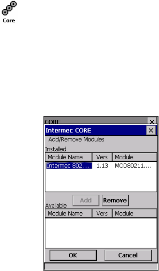
Windows Device ConfigurationsChapter —4
52 CV60 Vehicle-Mount Computer User's Manual
CORE
The Intermec CORE (Common Object Resource Environment) applicaĆ
tion provides a framework for various modules that let you configure and
manage your Intermec products. These modules are software plugĆins that
can be configuration tools, such as the 802.11b radio configuration modĆ
ule, or they can provide information on your environment, such as a batĆ
tery life module.
CORE modules are collections of specific information. Each module can
display general and detailed information. Tap the General and Details
tabs near the bottom to switch between general and detailed information.
Note that not all modules have detailed information.
Activating CORE
CORE is built into the operating system of Windows CE. NET for CV60
Vehicle Mount Computers. Tap Start > Programs > Core to access this
application.
Install an Available Radio Module
Windows CE
To install an available radio module onto your CV60 Vehicle Mount
Computer, tap Modules > Add/Remove, select a module from the bottom
Available box, then tap Add to put the selected module in the upper
Installed box. Click OK to exit the Add/Remove Modules screen.
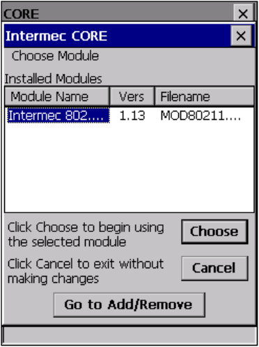
Windows Device Configurations—Chapter 4
53CV60 Vehicle-Mount Computer User's Manual
Loading a Radio Module
To load or switch to another radio module installed on the CV60 Vehicle
Mount Computer, tap Modules > Choose Module, select a module from
the Installed Modules box, then tap Choose to initialize and begin using
that module.
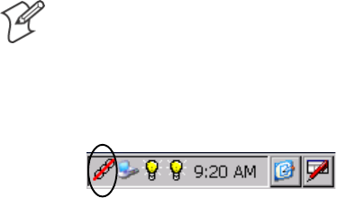
Windows Device ConfigurationsChapter —4
54 CV60 Vehicle-Mount Computer User's Manual
Note: Once CORE is running, you can return to it by tapping its icon
from the System Tray. Tap Start > Today > the Core threeĆring icon
(circled in the following illustration).
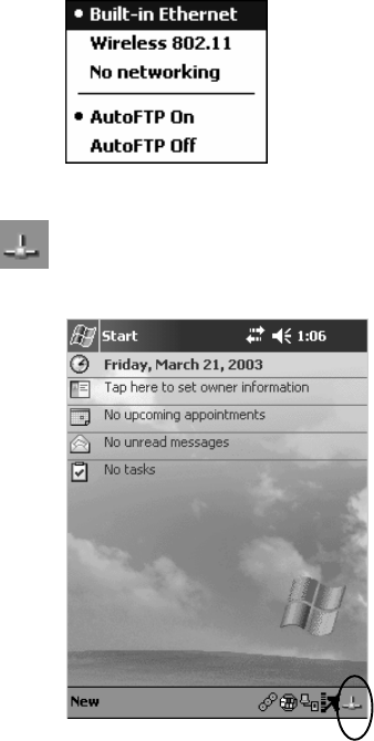
Windows Device Configurations—Chapter 4
55CV60 Vehicle-Mount Computer User's Manual
Ethernet Communications
Follow the steps below to start Ethernet communications on the CV60
Vehicle Mount Computer. If your system does not contain an 802.11b
radio, then Ethernet networking using DHCP is selected as the default.
When BuiltĆin Ethernet" is selected from the NDISTRAY popĆup menu
(the Network Driver Interface Specification tray application),
then the Ethernet icon shown to the left appears in the System Tray as
circled in the following illustration.
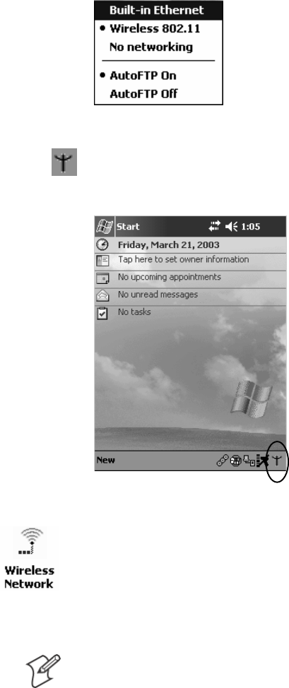
Windows Device ConfigurationsChapter —4
56 CV60 Vehicle-Mount Computer User's Manual
802.11b Communications
When Wireless 802.11" is selected via the NDISTRAY popĆup menu:
the 802.11 antenna icon shown to the left appears in the system tray as
circled in the following illustration.
To configure 802.11b communications on the CV60 Vehicle Mount
Computer, tap Start > Settings > the System tab > Wireless Network to
access the Profile Wizard for the 802.11b radio module. Go to Appendix
A, Configurable Settings," for configuration information.
802.11b Radio CORE Module
Note: See page 52 for information on loading this module in CORE.
The 802.11b radio CORE module displays helpful information about the
802.11b radio option built into your CV60 Vehicle Mount Computer.
Note that you can configure the 802.11b radio module from this CORE
application. Select Configure > Configure 802.11 CF from the bottom
menu bar to access the Profile Wizard application. See Appendix A, ConĆ
figurable Settings," for information about this application via the Wireless
Network control panel applet.
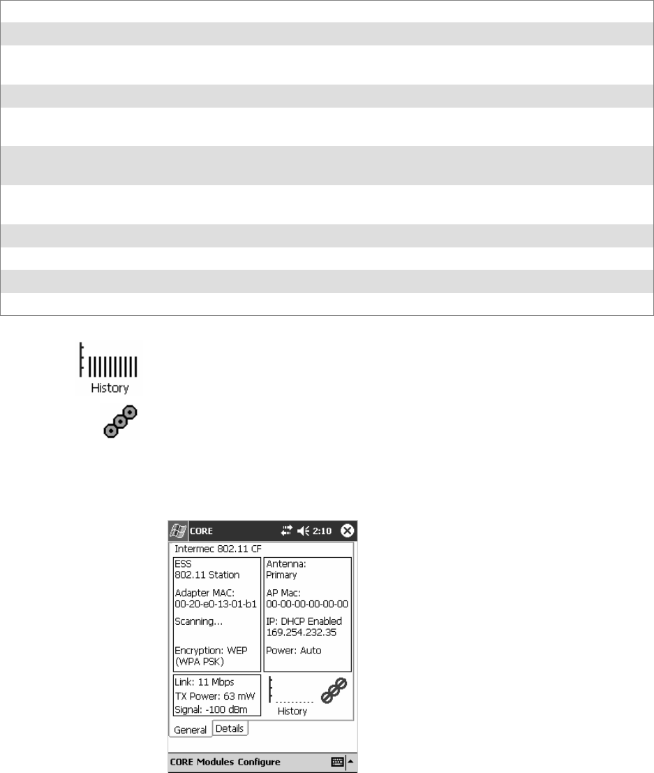
Windows Device Configurations—Chapter 4
57CV60 Vehicle-Mount Computer User's Manual
General
Below are descriptions and meanings for each piece of information proĆ
vided via the General tab. Note that the information is listed alphabetically.
Adapter MAC Identifies the MAC address for this 802.11b adapter.
Antenna Identifies the antenna used with the 802.11b radio: Primary," Secondary," or Diversity."
AP Mac Identifies the MAC address of the access point to which this CV60 Vehicle Mount Computer is conĆ
nected.
Connected to Reports the connection status and to which SSID this CV60 Vehicle Mount Computer is attached.
Encryption Reports the encryption mode and the association mode (in parantheses). See page NO TAG for inĆ
formation about WEP encryption.
ESS Identifies the type of network to which you are attached, either an ESS (Extended Service Set)
802.11 Station, or AdĆhoc.
IP Provides the IP address which can be set as either DHCP (Dynamic Host Configuration Protocol)
or statically.
Link Indicates the speed at which a connection is made.
Power Indicates the power status of this 802.11b profile.
Signal Identifies the radio signal strength (in dBm).
TX Power Shows the transmit power (in milliwatts) at which transmissions are made.
History:
This bar graph displays an active history of this radio module's quality of
connections.
Friendly Indicator:
This indicates the general quality of the 802.11b connection. Three filled
dots indicates the best quality; two filled dots dictates good quality; one
filled dot is of fair quality; and when all three dots are empty, the quality is
considered poor.
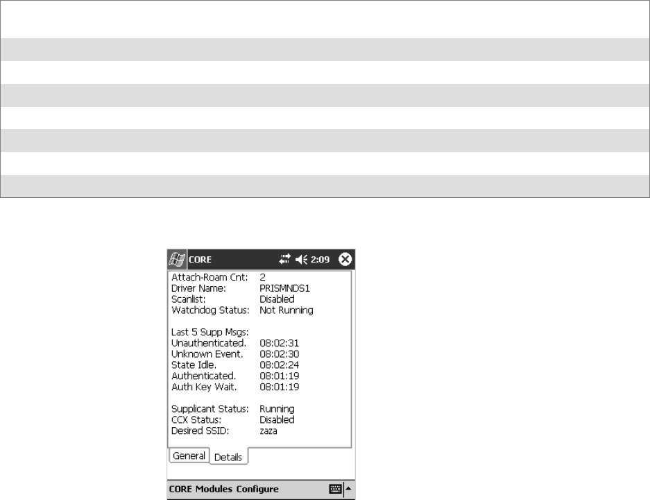
Windows Device ConfigurationsChapter —4
58 CV60 Vehicle-Mount Computer User's Manual
Details
Below are descriptions and meanings for each piece of information proĆ
vided via the Details tab. Note the information is listed alphabetically.
Attach-Roam Cnt Includes the number of new associations made during the current session, including any found
roaming.
CCX Status States the status of the CCX, either enabled or disabled.
Desired SSID Identifies the preferred Service Set Identifier (SSID).
Driver Name Identifies the 802.1x driver installed on this CV60 Vehicle Mount Computer.
Last 5 Supp Msgs Monitors and reports the 802.1x Security Supplicant activity.
Scanlist Indicates whether the Scan List option was enabled or disabled.
Supplicant Status Monitors the 802.1x security activity on the client: Running" or Stopped."
Watchdog Status Monitors the activity of the Scan List: Running" or Stopped."
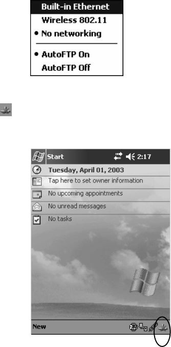
Windows Device Configurations—Chapter 4
59CV60 Vehicle-Mount Computer User's Manual
No Networking
When No networking" is selected from the NDISTRAY popĆup menu:
the disconnected icon shown to the left appears in the system tray as
circled in the following illustration.
Network Selection APIs
The Network Selection APIs change the network adapter configuration
programmatically. Both drivers support the same IOCTL function numĆ
bers for loading and unloading the drivers. Go to Chapter 7, ProgramĆ
ming," to see the APIs.
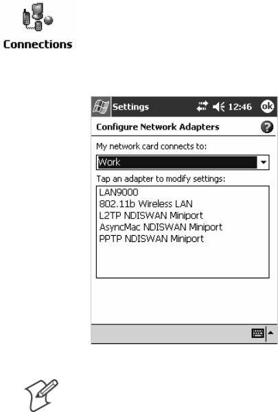
Windows Device ConfigurationsChapter —4
60 CV60 Vehicle-Mount Computer User's Manual
Network Connections
From the CV60 Vehicle Mount Computer, tap Start > Settings > NetĆ
work and Dialup Connections > PCI-E100CE1 > the Advanced tab >
Network Card to access the network connections for this unit. Make the
changes necessary for your network, then tap ok when finished.
Note: PCI-E100CE1" is for Ethernet and "802.11b Wireless LAN" is for
802.11b radios.
Wireless Printing
Bluetooth" is the name given to a technology standard using shortĆrange
radio links, intended to replace the cables connecting portable and fixed
electronic devices. The standard defines a uniform structure for a wide
range of devices to communicate with each other, with minimal user efĆ
fort. Its key features are robustness, low complexity, low power, and low
cost. The technology also offers wireless access to LANs, the mobile phone
network, and the internet for a host of home appliances and portable
handĆheld interfaces.
The Wireless Printing control panel separates the task of wireless printing
from the other Bluetooth management items not relevant to this task.
Wireless Printing has a concept of the current wireless printer". This
printer is the one to which the CV60 makes a connection when the wireĆ
less printing COM port is opened. If there is no current wireless printer,
there is no wireless printing COM port. Registration and deregistration of
this COM port is controlled by BTCC. The Wp_quickset_l.exe executable
calls BTCC when a printer is chosen to handle the COM port registration.
Customer software or other test applications can also use BTCC to manage
the COM port registration and deregistration.
The current wireless printer is stored in the registry and is registered and
deregistered on Bluetooth stack load/unload. If the current wireless printer
changes, the existing wireless printing COM port is deregistered, and the
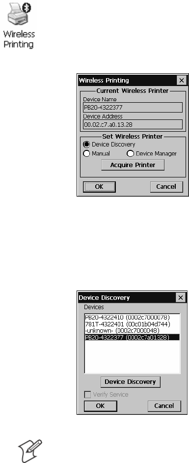
Windows Device Configurations—Chapter 4
61CV60 Vehicle-Mount Computer User's Manual
new one is registered instead. The registered COM port is stored in the
registry as the WPPort.
Windows CE
The following information pertains to the Windows CE operating system.
Wireless Printing
There are currently three ways to set the wireless printer. You can use a
Bluetooth device discovery to locate the remote device, you can manually
enter the remote Bluetooth Device Address, or you can use the Bluetooth
Device Manager to choose from previously discovered printers.
Use a Bluetooth Device Discovery
You can set your wireless printer via a Bluetooth Device Discovery, which
takes about half a minute to locate all Bluetooth devices in your range.
1From the CV60 desktop, select Start > Settings > Control Panel, then
doubleĆclick the Wireless Printing desktop icon.
2Make sure Device Discovery is selected in the Set Wireless Printer
box, and click Acquire Printer to initiate the device discovery.
3Momentarily, Bluetooth devices discovered within range appear. If your
preferred printer is in the list, select to highlight the printer, and click
OK If you do not see your preferred device, make sure this device is
powered on and set to discovery. Click Device Discovery again.
Note: Click Cancel to return to the first screen without making changes
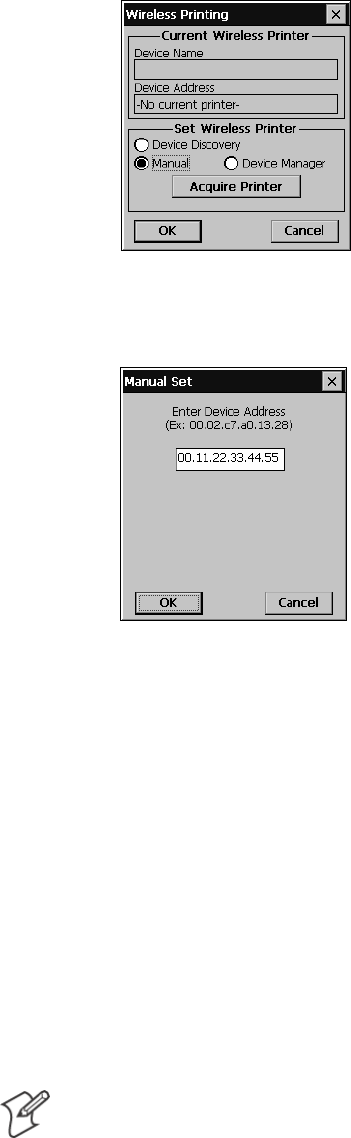
Windows Device ConfigurationsChapter —4
62 CV60 Vehicle-Mount Computer User's Manual
Enter the Remote Device Address
If you know the Bluetooth Device Address of the printer you want to use,
you can avoid Device Discovery and perform a manual setup.
1Select Manual from within the Set Wireless Printer box, then click AcĆ
quire Printer.
2Type the address of your device in the field, then click OK.
When you set your printer manually, your device does not receive the
printer name. Therefore, "-unknown-" is displayed under Device Name
unless you enter the correct value in to the registry in some other way.
HKEY_LOCAL_MACHINE\Software\Intermec\Bluetooth\Wireless
Printing
SRemoteDeviceAddress [String] - ex. 0002c7a01328
SRemoteDeviceAddress [String] - ex. PB20-4322377
SWPPort [String] - ex. COM6:
WPPort is the COM port to use in a call to CreateFile.
wp_quickset also alerts BTCC of Wireless Printer changes. When a new
wireless printer is set, wp_quickset calls BTCC, which then deregisters the
existing port (if necessary) and registers a new one based on the updated
remote Bluetooth device address.
Note: Click Cancel to return to the first screen without making changes
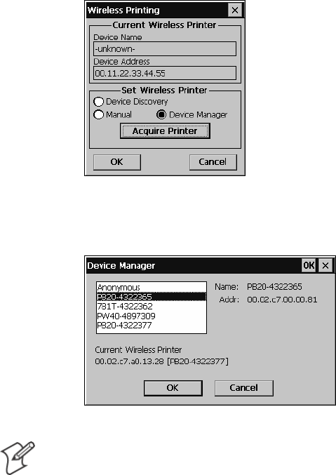
Windows Device Configurations—Chapter 4
63CV60 Vehicle-Mount Computer User's Manual
Choose from Previously Discovered Printers
Do the following to select from a list of previously discovered printers:
1Tap Device Manager from within the Set Wireless Printer box, then
click Acquire Printer.
2Select to highlight the printer of choice, then tap OK.
Note: Click Cancel to return to the first screen without making changes
Local Bluetooth
Local Bluetooth (Btlocal) is a Control Panel applet that views and sets local
device Bluetooth settings. Local Bluetooth also provides a versions screen
for various Bluetooth items in the system.
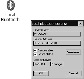
Windows Device ConfigurationsChapter —4
64 CV60 Vehicle-Mount Computer User's Manual
From the CV60 desktop, select Start > Settings > Control Panel, then
doubleĆclick the Local Bluetooth desktop icon.
SDevice Name
This provides the friendly" name of your CV60.
SDevice Address
Device address is universally unique and cannot be changed. ReadĆonly.
SDiscoverable
Check this box to make your CV60 discoverable to other Bluetooth deĆ
vices. The default is for the CV60 to be undiscoverable since it does not
offer any incoming services out of the box.
SConnectable
Check this box to allow other Bluetooth devices to connect to your
CV60. The default is for the CV60 to be unconnectable since it does
not offer any incoming services out of the box.
SClass of Device
This sets how your CV60 appears to other devices during a device disĆ
covery. The default is 0x920100 which specifies the CV60 is a PC capaĆ
ble of services of information, object transfer, and networking. Note that
though the CV60 identifies itself as having service classes, these services are
not supported as of this publication.
HKEY_LOCAL_MACHINE\Software\Intermec\Network\Bluetooth
SDiscoverable [DWORD] - 0=FALSE, 1=TRUE (Default is false)
SConnectable [DWORD] - 0=FALSE, 1=TRUE (Default is false)
SDeviceName [String] - ex. 720-6025320 not yet implemented
SCoD [?] - ex. ? not yet implemented
Windows XP
Information that pertains to the Windows XP and Windows XP EmĆ
bedded operating systems is not available as of this publication.
Windows Device Configurations—Chapter 4
65CV60 Vehicle-Mount Computer User's Manual
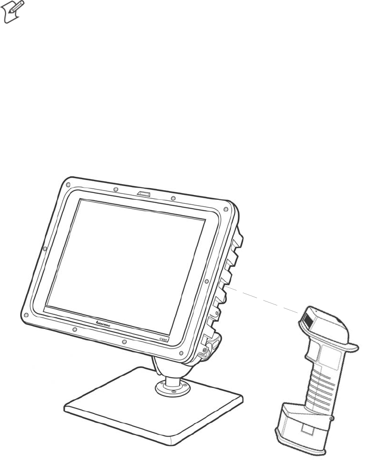
Windows Device ConfigurationsChapter —4
66 CV60 Vehicle-Mount Computer User's Manual
Picolink Radio
Note: To ensure the Picolink radio is enabled in your CV60, ensure the
COM2 serial port is turned on in the PhoenixBIOS Setup Utility. See
Chapter 3, PhoenixBIOS Setup Utility" for more information.
The Picolink radio is an Intermec product that is factoryĆinstalled into
your unit with a plate that covers the COM2 serial port at the bottom.
Wireless scanning capability is enabled using the Intermec Picolink radio,
compatible with the Intermec 1552 Decoded Cordless Laser wireless scanĆ
ner.
To associate the Picolink radio with your 1552 wireless scanner, scan the
Picolink bar code label located on the right side of your CV60 in the third
indented rib from the top.
Continue to scan the Picolink label on the CV60 until you hear two beeps from the 1552 Scanner.
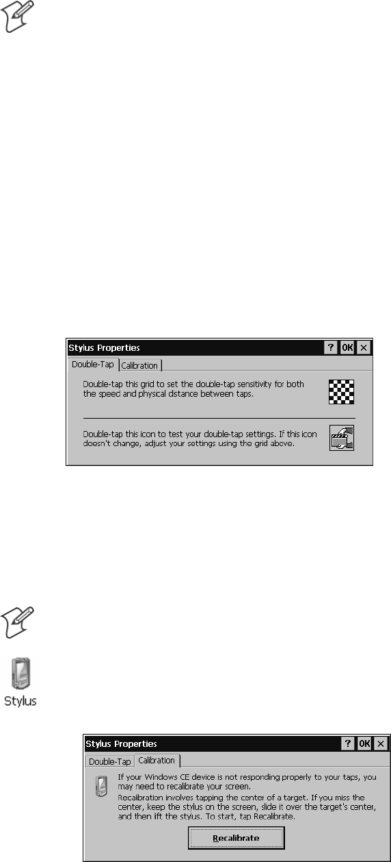
Windows Device Configurations—Chapter 4
67CV60 Vehicle-Mount Computer User's Manual
Note: To enable the touchscreen in units with Windows CE, set COM3 to
Enabled" within the PhoenixBIOS Setup Utility. In units with Windows
XP and Windows XP Embedded, set COM3 to OS Controlled." See
Chapter 3, PhoenixBIOS Setup Utility" for more information.
Stylus
When the CV60 Vehicle-Mount Computer is first reimaged to Windows
CE, Windows XP, or Windows XP Embedded or when it is necessary to
recalibrate (or realign) the touchscreen, use the Stylus Control Panel.
Windows CE
The following information pertains to the Windows CE operating system.
DoubleĆTap
Follow the instructions on this page to set the doubleĆtap sensitivity of
your stylus. Tap OK when finished.
Calibration
This applet calibrates the stylus for the CV60, aligning the Windows curĆ
sor and stylus to the same location on the screen. When complete, the calĆ
ibration values are stored permanently until the next time you do a calibraĆ
tion.
Note: In situations where the touchscreen calibration is off base or is not
usable, use the external keyboard to navigate to the calibration screen.
1From the CV60 desktop, select Start > Settings > Control Panel,
doubleĆtap the Stylus icon to access the Stylus Properties, then tap the
Calibration tab. Tap Recalibrate to begin.
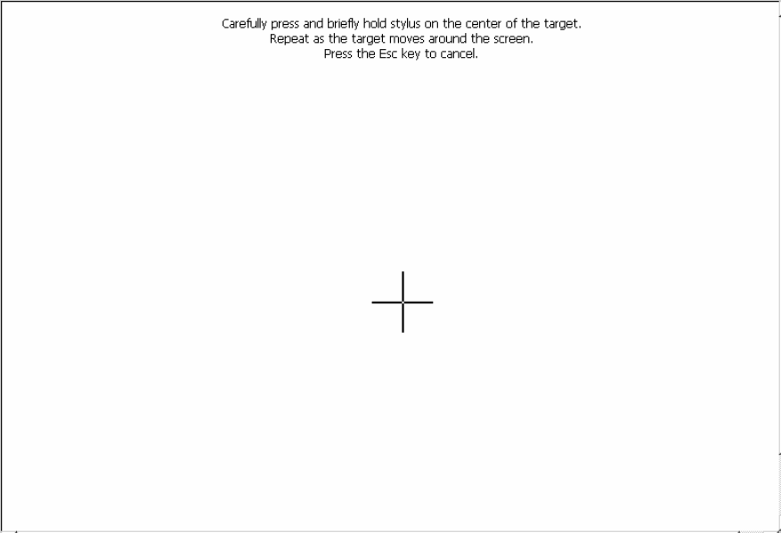
Windows Device ConfigurationsChapter —4
68 CV60 Vehicle-Mount Computer User's Manual
2Tap your stylus firmly at the center of the crosshairs target. Continue
the process as the crosshair moves to the upperĆleft corner, the bottomĆ
left, the bottomĆright, and upperĆright corners of the screen.
3After all targets are tapped, a message appears to indicate that new calĆ
ibration settings have been measured. Press [Enter] on the external keyĆ
board to accept the new settings and return to the Stylus Properties
screen, or press [Esc] to do another calibration.
4Tap OK to close the Stylus Properties screen.
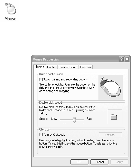
Windows Device Configurations—Chapter 4
69CV60 Vehicle-Mount Computer User's Manual
Windows XP
The following information pertains to the Windows XP and Windows XP
Embedded operating systems.
DoubleĆTap
Use the Mouse control panel applet to adjust the doubleĆtap sensitivity of
your stylus.
1From the Windows desktop, select Start > Settings > Control Panel,
then doubleĆclick the Mouse desktop icon.
2From the center DoubleĆclick speed box, drag the Speed bar to slower
or faster, then test the sensitivity between taps on the folder.
3When satisified with your doubleĆtap sensitivity, click Apply to save
your settings, then click OK to close the Mouse Proprties.
Calibration
When the CV60 is first reimaged to Windows XP or Windows XP EmĆ
bedded or when it is necessary to recalibrate (or realign) the touchscreen,
use the CV60 Pen Alignment Utility. This utility is located in the WinĆ
dows Control Panel.
The CV60 Pen Alignment Utility calibrates the pen for the CV60, alignĆ
ing the Windows cursor and tip of the stylus to the same location on the
screen. When complete, the calibration values are stored permanently.
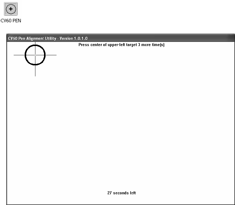
Windows Device ConfigurationsChapter —4
70 CV60 Vehicle-Mount Computer User's Manual
1From the Windows desktop, select Start > Settings > Control Panel,
then doubleĆclick the CV60 PEN desktop icon to access the CV60 Pen
Alignment Utility.
2Tap your stylus firmly at the center of the crosshairs target in the upperĆ
left corner. You should hear a click and see two sets of x,y coordinate
values display on the screen. Tap two more times in this same way at the
center of this target.
3Continue the threeĆtap process as the crosshair moves to the upperĆright
corner, the lowerĆleft, and lowerĆright corners of the screen.
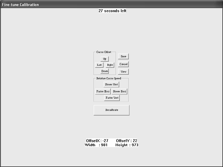
Windows Device Configurations—Chapter 4
71CV60 Vehicle-Mount Computer User's Manual
4Touch on an open area to determine if the Windows cursor matches the
location your stylus. Click Recalibrate if there is no match. When finiĆ
shed, click Save to permanently save the new values or click Cancel to
continue using the old calibration.
SLeft
Move the cursor to the left with respect to your stylus.
SRight
Move the cursor to the right with respect to your styls.
SUp
Move the cursor up with respect to your stylus.
SDown
Move the cursor down with respect to your stylus.
SSlowerVert
Moves the cursor more slowly in the vertical direction with respect to
your stylus. Use this when the cursor matches at the top of the screen,
but is lower than the tip of your stylus at the bottom of the screen.
SFasterVert
Moves the cursor more quickly in the vertical direction with respect to
your stylus. Use this when the cursor matches at the top of the screen,
but is higher than the tip of your stylus at the bottom of the screen.
SSlowerHorz
Works like SlowerVert, except movement is in the horizontal direction.
SFasterHorz
Works like FasterVert, except movement is in the horizontal direction.
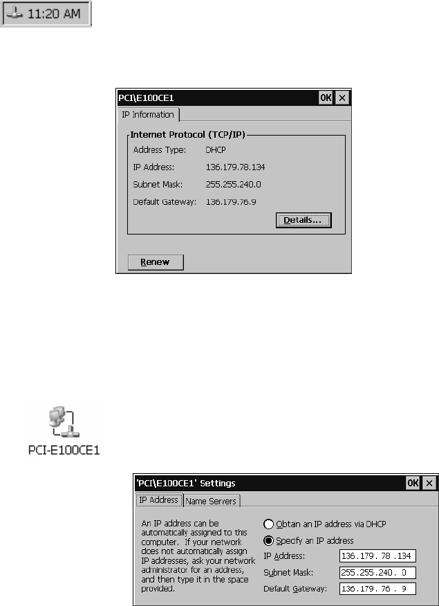
Windows Device ConfigurationsChapter —4
72 CV60 Vehicle-Mount Computer User's Manual
TCP/IP
This section contains Transmission Control Protocol/Internet Protocol
(TCP/IP) network information supported for the CV60. This protocol
readies the CV60 for communications.
By default, the Local Area Connection is set to obtain an IP address and a
DNS server address automatically on your CV60.
Windows CE
The following information pertains to the Windows CE operating system.
To determine what type of Ethernet connection is set up on your CV60,
tap the Ethenet icon twice in your System Tray to access the following inĆ
formation. Tap Renew to refresh this information.
Do the following to assign static IP and DNS addresses:
1From the CV60 desktop, tap Start > Settings > Network and DialĆup
Connections.
2DoubleĆtap the PCIĆE100CE2 icon to get its settings. Under the IP
Address tab, tap Specify an IP address, then complete the information:
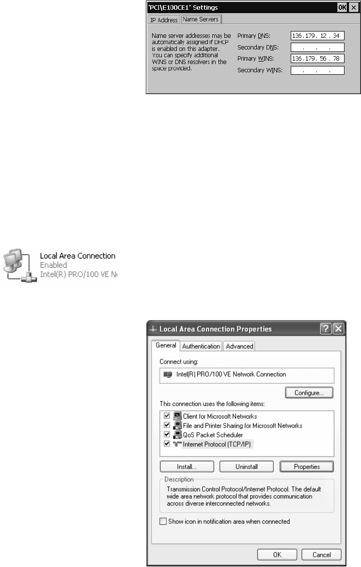
Windows Device Configurations—Chapter 4
73CV60 Vehicle-Mount Computer User's Manual
3Tap the Name Servers tab, then complete the information. Be sure to
complete at least the primary addresses:
4Tap OK to close the Settings, then close the Network Connections
screen.
Windows XP
The following information pertains to the Windows XP and Windows XP
Embedded operating systems.
Do the following to assign static IP and DNS addresses:
1From the CV60 desktop, tap Start > Settings > Network Connections.
2Press and hold the stylus on the Local Area Connection icon to get its
popĆup menu, then select Properties.
3Select to highlight the Internet Protocol (TCP/IP) option, then tap
Properties.
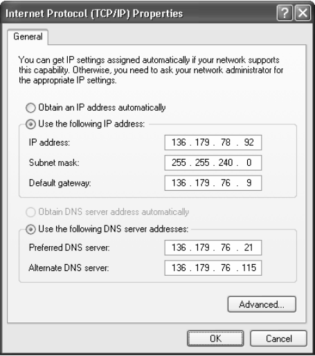
Windows Device ConfigurationsChapter —4
74 CV60 Vehicle-Mount Computer User's Manual
4Ta p Use the following IP address, then complete both the IP address
and DNS addresses.
5Tap OK to close the TCP/IP Propertiess, tap OK again to close the LoĆ
cal Area Connections screen.
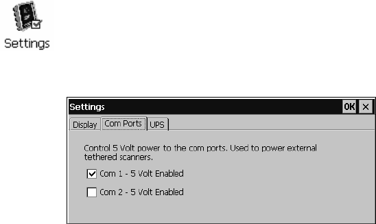
Windows Device Configurations—Chapter 4
75CV60 Vehicle-Mount Computer User's Manual
Tethered Scanner
The Intermec Tethered Scanner feature allows Automatic Data Collection
(ADC) by accepting data from the COM1 port and wedging it into the
keyboard interface. This feature is enabled or disabled via the Intermec
Settings and Settings control panel applets.
Windows CE
Enabling and Disabling
From the CV60 desktop, select Start > Settings > Control Panel, then
doubleĆclick the Settings desktop icon. Click the Com Ports tab, then
click Com 1 Ć 5 Volt Enabled to activate the tethered scanner. See page 44
for more information about this control panel applet.
Scanner Cabling
Sabre 1551E / 1553 Cables connect directly to the CV60 COM Port.
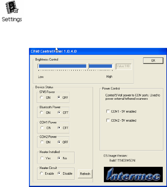
Windows Device ConfigurationsChapter —4
76 CV60 Vehicle-Mount Computer User's Manual
Windows XP
Enabling and Disabling
From the CV60 desktop, select Start > Settings > Control Panel, then
doubleĆclick the CV60 icon. Click the Com 1 Ć 5 Volt Enabled checkbox
to activate the tethered scanner.
Windows Device Configurations—Chapter 4
77CV60 Vehicle-Mount Computer User's Manual
Scanner Cabling
Sabre 1551E / 1553 Cables connect directly to the CV60 COM Port.
When enabled, the 1551/1553 menu option has these capabilities:
SGrid Data Editing is available.
SThe source of the symbology configurations is only available via the
Easy Set command labels. Only the Virtual Wedge configurations can be
configured via the Intermec Settings control panel applet.
SMay transmit the data through the keyboard interface (via the Virtual
Wedge).
SThe bar code APIs, defined in the IADC interface, are available to get
bar code data from the bar code scanner. The following example shows
how to programmatically collects bar code data:
#include IADC.h" // Linked with ITCUUID.LIB
#include ITCAdcMgmt.h" // Linked with ITCAdcDevMgmt.lib
IADC* pIADC;
HRESULT hrStatus = S_OK;
// Create a ADC COM interface to collect bar code data from the 1551E/1553
// when the 1551/1553 menu option is enabled.
hrStatus =
ITCDeviceOpen(TEXT(ExtScanner"), // Name of the ADC device.
IID_IADC, // COM interface to return
ITC_DHDEVFLAG_READAHEAD, // Device's Flags
(LPVOID *) &pIADC); // the returned interface
if( SUCCEEDED(hrStatus) )
{
BYTE byteBuffer[MAX_LABEL_SIZE];
DWORD dwLength = 0;
HRESULT hr = pIDC->Read(
byteBuffer, // Buffer to put the ADC data.
MAX_LABEL_SIZE, // Size of pDataBuffer in bytes.
&dwLength, // Number bytes returned.
NULL, // Time stamp of the received data. NULL.
INFINITE // Number of milliseconds to wait.
);
}
when done using this COM interface, delete it:
ITCDeviceClose( (IUnknown **) pIADC);

Windows Device ConfigurationsChapter —4
78 CV60 Vehicle-Mount Computer User's Manual
How to configure tethered scanners 1551E/1553/1800/1400
Tethered scanners can be configured from the Intermec Settings" on the
CV60. Follow these steps:
1Connect a tethered scanner to the tethered scanner port.
2Under the tethered scanner folder, select the scanner model to match the
attached scanner type. If the scanner port state is not already enabled,
then enable it.
Note: during this process the terminal is trying to communicate to the atĆ
tached scanner.
You will see a Failed to save one or more settings" message if:
Sthe scanner is not powered
Sthe cable is not properly connected
Sif the wrong cable is used
Sif the scanner firmware is older than version 2.0.
Note: that this process can take up to 8 seconds since the terminal is going
through a group of RS323 settings to trying to communicate with the
scanner.
The auto-baud process is performed whenever the scanner port state is
changed from Disable to Enable or whenever the 1551E/1553 is selected
from the scanner model list and the scanner port state is enabled.
If the auto-baud process is successful, about eight beeps will be generated,
and it is followed by another series of beeps depending on the firmware
version installed in the scanner. The latter series of beeps are suppressed
since FW 2.08.

79CV60 Vehicle-Mount Computer User's Manual
Developing and Installing
Applications
5
In this chapter you will find guidelines for developing applications using
the Software Developer's Kit (SDK) and converting existing Trakker AnĆ
tares applications using the Programmer Software Kit (PSK).
The CV60 can be ordered with a choice of three operating systems: WinĆ
dows CE, Windows XP, and Windows XP Embedded (XPE).
The following are references to the operating systems, used throughout this
chapter:
SCV60 CE refers to Windows CE platform.
SCV60 XP/XPE refers to the XP and XP Embedded platforms.
SCV60 refers to all three platforms.
Developing and Installing ApplicationsChapter —5
80 CV60 Vehicle-Mount Computer User's Manual
Developing Applications for the CV60
The CV60 Vehicle-Mount Computer runs applications programmed in
Microsoft C++ and also run applications developed for the .NET frameĆ
work using Microsoft C#.
Use this section to understand how to:
SConvert a Trakker Antares application to a CV60 application
SDevelop a new application for the CV60
SDevelop a web-based application for the CV60
Developing a New Application for the CV60
Use the Intermec SDK to develop new applications to run on the CV60.
The Intermec SDK is a library of C++ language functions you can use to
create applications for the CV60.
See the SDK online user's manual for help developing your application.
The Intermec SDK User's Manual contains hardware and software requireĆ
ments, all of the functions that are supported by the CV60, and how to
use these functions.
You need these hardware and software components to use the Intermec
SDK:
SPentium PC, 400 MHz or higher
SWindows 2000 (Service Pack 2 or later) or Windows XP (Home, ProĆ
fessional, or Server)
SFor CV60 CE: Microsoft eMbedded Visual C++ version 4.0 with
Service Pack 2 for native C++ development
SFor CV60 XP/XPE: Microsoft Visual C++ 6.0 and the Microsoft
Platform SDK
S128MB RAM (196MB recommended)
S360MB Hard drive space for minimum installation (720MB for comĆ
plete)
SCD-ROM drive compatible with multimedia PC specification
SVGA or higher-resolution monitor (Super VGA recommended)
SMicrosoft Mouse or compatible pointing device
The SDK is part of the Intermec Developer's Library (IDL) and is availĆ
able on CD (P/N 235-114-001) or as a download from the Intermec web
site at www.intermec.com.

Developing and Installing Applications—Chapter 5
81CV60 Vehicle-Mount Computer User's Manual
Converting a Trakker Antares Application to a CV60 CE Application
If you have an existing Trakker Antares application that you would like to
run on the CV60, you can use the Programmer's Software Kit (PSK) to
convert it. The CV60 PSK is a set of libraries and tools that you use to
convert your existing Trakker Antares C applications into C/C++ applicaĆ
tions for use on your CV60 CE Data Collection Computer.
Note: Only CV60 CE supports the PSK.
The CV60 does not support all Trakker Antares PSK functions. You may
need to rewrite parts of your application when converting it for use on the
CV60.
See the PSK online manual for a list of functions that are not supported.
You need these hardware and software components to use the PSK:
SPC with at least 300 MB of free disk space running Microsoft WinĆ
dows 2000/XP.
SMicrosoft eMbedded Visual C++ version 4.0 with Service Pack 2
SIntermec SDK and development tools
SIntermec PSK whick contains these files and utilities:
SPSK functions library
SHeader files
SExample files
The PSK is part of the Intermec Developer's Library (IDL) and is available
on CD (P/N 235-114-001) or as a download from the Intermec web site
at www.intermec.com.
Developing a Web-Based Application
You can develop web-based data collection applications for use on the
CV60. For help, see any HTML source book. The CV60 ships with
Internet Explorer 6.0.
Developing and Installing ApplicationsChapter —5
82 CV60 Vehicle-Mount Computer User's Manual
Installing Applications on the CV60
You can install files and applications on the CV60 several ways; if you have
a simple application, you might only need to deliver the EXE file. You can
simply copy a directory structure that contains the application, supporting
files, DLLs, images, sound files, and data files to the device.
For CV60 CE, you can package your application as a cabinet (CAB) file.
The delivery methods are:
SActiveSync
SWavelink Avalanche
SDrive mapping.
The following sections explain each of these processes you use to install
your application on the CV60.
All CV60:
Installing Applications Using Wavelink Avalanche
You can use the Wavelink Avalanche device management system to install
applications on all of your wireless CV60s.
The CV60 ships with the Avalanche Enabler already installed. Each time
the Avalanche Enabler is activated (typically on a warm boot), the CV60
attempts to connect to the Avalanche Agent. When the CV60 connects to
the agent, the agent determines whether an update is available and immeĆ
diately starts the software upgrade, file transfer, or configuration update.
To use Avalanche to remotely manage the CV60
1Install software packages and updates for the CV60 using the Avalanche
Administrative Console.
2Schedule the CV60 updates or manually initiate an update using the
Avalanche Administrative Console.
For more information on using Wavelink Avalanche, contact your local
Intermec representative or visit the Wavelink web site
at www.wavelink.com.
CV60 CE only:
Using ActiveSync to Install Applications
You can use ActiveSync to establish a connection between your desktop PC
and the CV60 CE. ActiveSync allows you to transfer files, synchronize files,
perform remote debugging, and other device management activities.
ActiveSync is a free application available from the Microsoft web site at
http://www.microsoft.com (search for ActiveSync).
To establish a partnership between your desktop PC and the CV60 CE,
you will need:
SFemale-to-female null modem serial cable
SActiveSync version 3.7 or later.
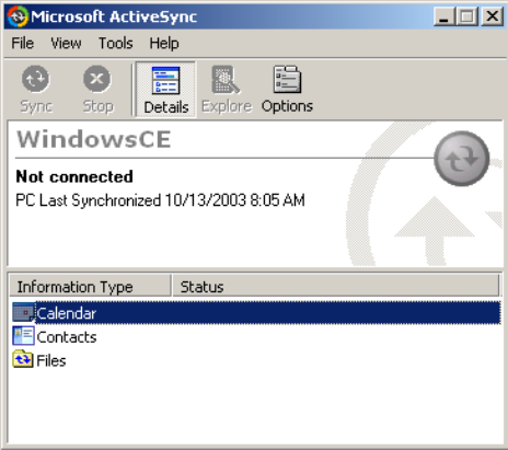
Developing and Installing Applications—Chapter 5
83CV60 Vehicle-Mount Computer User's Manual
Installing ActiveSync and Establishing a Partnership
You can use a serial cable to establish your initial partnership between the
CV60 CE and your desktop PC.
To install ActiveSync and establish a partnership
1Download ActiveSync from the Microsoft web site and follow the onsĆ
creen instructions for installing it on your desktop PC.
2When the installation process is complete, the Get Connected dialog
box appears.
3Connect the CV60 CE to your desktop PC with the serial cable.
4Click Next in the Get Connected dialog box. ActiveSync detects a deĆ
vice on the serial port and prompts you to set up a new partnership.
5In the Set Up a Partnership dialog box, click Next.
6In the Select Number of Partnerships dialog box, select Yes, I want to
synchronize with only this computer and then click Next.
7In the Select Synchronization Settings dialog box, check the items you
want to synchronize and click Next.
8In the Setup Complete dialog box, click Finish.
When the partnership is established, the following screen appears on your
desktop showing the device name of your CV60 and the Connected status.

Developing and Installing ApplicationsChapter —5
84 CV60 Vehicle-Mount Computer User's Manual
The Microsoft ActiveSync Screen
An ActiveSync icon ( ) also appears on the CV60 CE status bar indiĆ
cating that it has established an ActiveSync partnership with your desktop
PC.
Note: If ActiveSync does not establish a partnership on the first try, the
Get Connected dialog box appears on your desktop with the message
Your device was not detected." Click Next on the Get Connected dialog
box until your device is detected.
Now that the partnership has been established, ActiveSync initiates all fuĆ
ture connections.
Using ActiveSync to Copy Files and Install Applications
You can use ActiveSync to copy files to the CV60 CE and to install apĆ
plications. To install an application, you need to copy the CAB file to a
directory on the CV60 CE and then run it. Use the following procedures
to learn how to copy files and install applications on the CV60 CE using
ActiveSync.
To install an application on the CV60 CE using ActiveSync
1Connect the CV60 CE to your desktop PC using ActiveSync. For help,
see the previous section, Installing ActiveSync and Establishing a PartĆ
nership."
2In the Microsoft ActiveSync screen, click Explore. Windows Explorer
opens the Mobile Device window of your CV60 CE.
3In Windows Explorer on your desktop PC, browse to the file that you
want to copy to your CV60 CE.
4Right-click the file and click Copy.
5Place the cursor in the folder of your CV60 CE, right-click, and click
Paste.
The file has now been copied to the CV60 CE and you can see it using the
CV60 CE File Manager. Navigate to your application file and run it.
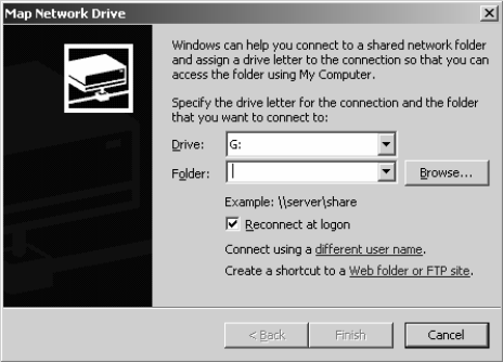
Developing and Installing Applications—Chapter 5
85CV60 Vehicle-Mount Computer User's Manual
CV60 XP/XPE:
Mapping a network drive:
You can transfer files between your desktop PC and the CV60 XP/XPE by
mapping a network drive.
To map a network drive, perform the following steps:You may need help
from your IT department for some of the following steps.
1From your desktop, right-click My Network Places, and from the pop-
up menu select Map Network Drive.
2From the drive drop-down menu, select the drive you wish to map.
3In the Shared Directories menu, click the directory you are going to
map.
4You may wish to map to a folder inside a network drive. If so, double-
click the directory to expose the underlying folders. Click the desired
folder.
5The information about the drive you are mapping is shown at the top of
the Map Network Drive pop-up window.
6Drive: The chosen drive.
7Path: Specified path to desired folder in chosen drive. Connect As: Your
login name.
8Click OK.
Developing and Installing ApplicationsChapter —5
86 CV60 Vehicle-Mount Computer User's Manual

87CV60 Vehicle Mount Computer User's Manual
Connector Pinouts
6
This chapter details the CV60 Vehicle-Mount Computer connectors.
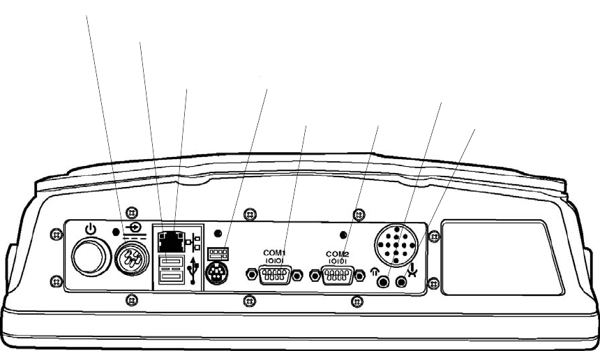
Connector PinoutsChapter —6
88 CV60 Vehicle Mount Computer User's Manual
Connectors
Connectors are located on the bottom of the computer and are identified
below.
Network
USB Connectors
Power Connector
PS/2 Keyboard
COM1 COM2
Headphone
Microphone
Connectors
Each COM serial port has its own address and uses a 9-pin male connector
to attach RS-232 serial devices, such as a printer, a mouse, an external moĆ
dem, a scanner, or a serial network connection.
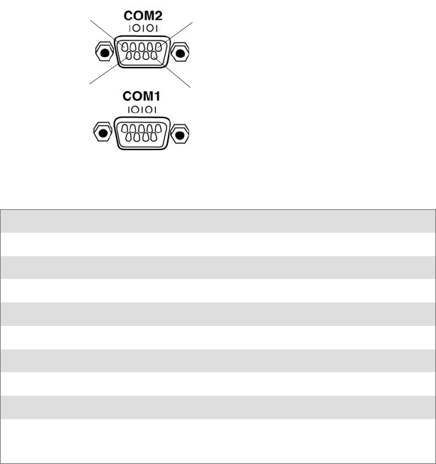
Connector Pinouts
—Chapter 6
89CV60 Vehicle Mount Computer User's Manual
COM Port Pinout
15
69
COM Port Pinout (COM1 & COM2 identical)
Pin Description
1RS232 DCD
2RS232 RXD
3RS232 TXD
4RS232 DTR
5GND
6RS232 DSR
7RS232 RTS
8RS232 CTS
9RS232 RI & +5V for external
tethered scanner
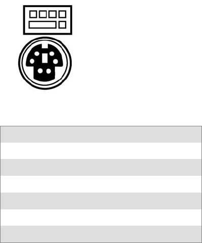
Connector PinoutsChapter —6
90 CV60 Vehicle Mount Computer User's Manual
Keyboard PS/2
This 6-pin mini-DIN, PS/2-standard connectors connect an external keyboard
to the computer.
Where an external keyboard is not connected to the computer, you may use
an emulated keyboard (if available in your application) that can be activated
on the display.
6
4
21
3
5
Pin Description
1Keyboard Data
2 NC
3GND
4 NC
5 +5 Volts DC
6Keyboard Clock
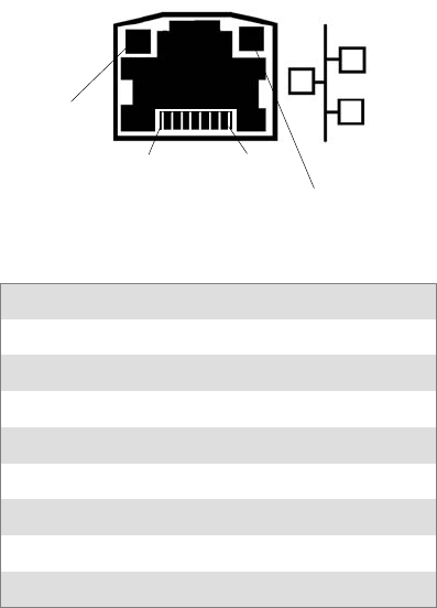
Connector Pinouts
—Chapter 6
91CV60 Vehicle Mount Computer User's Manual
Ethernet
The RJ-45 type 8-pin modular connector shown below provides an interĆ
face to an Ethernet local area network. Pinouts are as shown below when
the user views the connector straight on from the outside of the computer.
Once a valid link is detected, whether it is 10Base-T or 100Base-T, the
green LED light on the connector will be ON. The yellow LED flash will
if there is any activity on the Ethernet LAN port.
1
8
Green
LED
Yellow
LED
Pin Signal
1TX+
2TX-
3 RX+
4GND
5GND
6 RX-
7GND
8GND
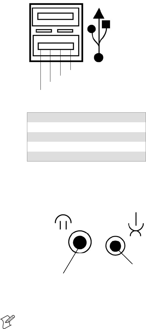
Connector PinoutsChapter —6
92 CV60 Vehicle Mount Computer User's Manual
USB Connectors
There are 2 external USB 1.1 ports that can be used for connection to
common serial type devices such as a mouse or keyboard.
1
2
3
4
Pin Signal
1 +5V
2 USB_DATA-
3 USB_DATA+
4 Ground
Audio Connections
The microphone and headphone jacks are shown below.
Microphone / Headphone
Headphone
Jack
Microphone
Jack
Note: The headphone jack functions as an audio line out, and the speaker
audio is not disconnected. The microphone jack is a combination mic/
headset jack which disconnects the speaker when the plug is inserted.

Connector Pinouts
—Chapter 6
93CV60 Vehicle Mount Computer User's Manual
Power Connector Pin out
1
2
34
5
Pin Description
1 Chassis GND
2System Line
3System Neutral
4 Heater Neutral
5 Heater Line
Connector PinoutsChapter —6
94 CV60 Vehicle Mount Computer User's Manual

Corporate Headquarters
6001 36th Avenue West
Everett, Washington 98203
tel 425.348.2600
fax 425.355.9551
www.intermec.com
*961054033B*
*961-054 -033B* Rev B
CV60 User’s Manual - October 2004
U.S.A