Intermec Technologies 802UIAG 802UIAG User Manual CK60UserManual WinCE
Intermec Technologies Corporation 802UIAG CK60UserManual WinCE
Contents
Users Manual
CK60 Series Mobile Computer User’s Manual i
CK60 Handheld
Computer with
Windows CE
User's Manual
ii CK60 Handheld Computer with Windows CE User’s Manual
Intermec Technologies Corporation
Corporate Headquarters Cedar Rapids Technical Communications
6001 36th Ave.W. 550 Second Street SE
Everett, WA 98203 Cedar Rapids, IA 52401
U.S.A. U.S.A.
www.intermec.com
The information contained herein is proprietary and is provided solely for the purpose of allowing
customers to operate and service Intermec-manufactured equipment and is not to be released, repro-
duced, or used for any other purpose without written permission of Intermec.
Information and specifications contained in this document are subject to change without prior
noticed and do not represent a commitment on the part of Intermec Technologies Corporation.
© 2005 by Intermec Technologies Corporation. All rights reserved.
The word Intermec, the Intermec logo, Norand, ArciTech, CrossBar, Data Collection Browser,
dcBrowser, Duratherm, EasyADC, EasyCoder, EasyLAN, Enterprise Wireless LAN, EZBuilder, Fin-
gerprint, i-gistics, INCA (under license), InterDriver, Intermec Printer Network Manager, IRL,
JANUS, LabelShop, Mobile Framework, MobileLAN, Nor*Ware, Pen*Key, Precision Print, Print-
Set, RoutePower, SmartSystems, TE 2000, Trakker Antares, and Virtual Wedge are either trade-
marks or registered trademarks of Intermec Technologies Corporation.
Throughout this manual, trademarked names may be used. Rather than put a trademark (™ or ®)
symbol in every occurrence of a trademarked name, we state that we are using the names only in an
editorial fashion, and to the benefit of the trademark owner, with no intention of infringement.
There are U.S. and foreign patents pending.
Bluetooth is a trademark of Bluetooth SIG, Inc., U.S.A.
Contents
CK60 Handheld Computer with Windows CE User’s Manual iii
Contents
Before You Begin . . . . . . . . . . . . . . . . . . . . . . . . . . . . . . . . . . . . . . . . . . . . . . . . . . . . . . . . .ix
Safety Summary . . . . . . . . . . . . . . . . . . . . . . . . . . . . . . . . . . . . . . . . . . . . . . . . . . . ix
Safety Icons. . . . . . . . . . . . . . . . . . . . . . . . . . . . . . . . . . . . . . . . . . . . . . . . . . . . . . . x
Global Services and Support. . . . . . . . . . . . . . . . . . . . . . . . . . . . . . . . . . . . . . . . . . xi
Who Should Read this Manual. . . . . . . . . . . . . . . . . . . . . . . . . . . . . . . . . . . . . . . . xi
Related Documents . . . . . . . . . . . . . . . . . . . . . . . . . . . . . . . . . . . . . . . . . . . . . . . xii
Patent Information . . . . . . . . . . . . . . . . . . . . . . . . . . . . . . . . . . . . . . . . . . . . . . . . xii
1 Using the CK60 Handheld Computer
. . . . . . . . . . . . . . . . . . . . . . . . . . . . . . . . . . . . . . . 1
Introducing the CK60 Handheld Computer . . . . . . . . . . . . . . . . . . . . . . . . . . . . . . . . . . . . 2
Learning Software Build Versions . . . . . . . . . . . . . . . . . . . . . . . . . . . . . . . . . . . . . . . . . . . . 3
Resetting Your CK60 Computer . . . . . . . . . . . . . . . . . . . . . . . . . . . . . . . . . . . . . . . . . . . . . 3
Performing a Warm-Boot on the CK60 Computer. . . . . . . . . . . . . . . . . . . . . . . . . 3
Performing a Cold-Boot on the CK60 Computer. . . . . . . . . . . . . . . . . . . . . . . . . . 3
Scanning Bar Codes. . . . . . . . . . . . . . . . . . . . . . . . . . . . . . . . . . . . . . . . . . . . . . . . . . . . . . . 4
Scanning with the 2D Area Imager. . . . . . . . . . . . . . . . . . . . . . . . . . . . . . . . . . . . . 4
Supported Devices . . . . . . . . . . . . . . . . . . . . . . . . . . . . . . . . . . . . . . . . . . . . . . . . . 5
Using the Ambient Light Sensor . . . . . . . . . . . . . . . . . . . . . . . . . . . . . . . . . . . . . . . . . . . . . 5
Using the Battery. . . . . . . . . . . . . . . . . . . . . . . . . . . . . . . . . . . . . . . . . . . . . . . . . . . . . . . . . 6
Changing and Installing the Battery . . . . . . . . . . . . . . . . . . . . . . . . . . . . . . . . . . . . 6
Maximizing Battery Life . . . . . . . . . . . . . . . . . . . . . . . . . . . . . . . . . . . . . . . . . . . . . 7
Checking the Battery Status . . . . . . . . . . . . . . . . . . . . . . . . . . . . . . . . . . . . . . . . . . 7
Using the Keypad . . . . . . . . . . . . . . . . . . . . . . . . . . . . . . . . . . . . . . . . . . . . . . . . . . . . . . . . 8
32-Key Large Numeric Keypad. . . . . . . . . . . . . . . . . . . . . . . . . . . . . . . . . . . . . . . . 9
45-Key Full Alphanumeric Keypad. . . . . . . . . . . . . . . . . . . . . . . . . . . . . . . . . . . . . 9
58-Key Full Alphanumeric Keypad. . . . . . . . . . . . . . . . . . . . . . . . . . . . . . . . . . . . 10
Using the Color-Coded Keys . . . . . . . . . . . . . . . . . . . . . . . . . . . . . . . . . . . . . . . . 10
Capitalizing All Characters . . . . . . . . . . . . . . . . . . . . . . . . . . . . . . . . . . . . . . . . . . 11
Typing Alphabetical Characters on the 45-Key Keypad . . . . . . . . . . . . . . . . . . . . 11
Using the Power (I) Key . . . . . . . . . . . . . . . . . . . . . . . . . . . . . . . . . . . . . . . . . . . . 11
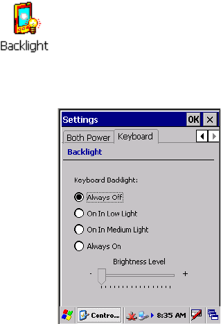
Turning on the Keypad Backlight. . . . . . . . . . . . . . . . . . . . . . . . . . . . . . . . . . . . . 11
Using the Screen . . . . . . . . . . . . . . . . . . . . . . . . . . . . . . . . . . . . . . . . . . . . . . . . . . . . . . . . 12
Using the Speakers. . . . . . . . . . . . . . . . . . . . . . . . . . . . . . . . . . . . . . . . . . . . . . . . . . . . . . . 13
Enabling the Speaker and Adjusting the Volume . . . . . . . . . . . . . . . . . . . . . . . . . 13
Disabling the Speaker . . . . . . . . . . . . . . . . . . . . . . . . . . . . . . . . . . . . . . . . . . . . . . 14
Using the Status Lights . . . . . . . . . . . . . . . . . . . . . . . . . . . . . . . . . . . . . . . . . . . . . . . . . . . 14
Using the Secure Digital Card . . . . . . . . . . . . . . . . . . . . . . . . . . . . . . . . . . . . . . . . . . . . . . 15
Physical and Environmental Specifications . . . . . . . . . . . . . . . . . . . . . . . . . . . . . . . . . . . . 16
Contents
iv CK60 Handheld Computer with Windows CE User’s Manual
Accessories for the CK60 Computer . . . . . . . . . . . . . . . . . . . . . . . . . . . . . . . . . . . . . . . . . 17
2 Windows CE
. . . . . . . . . . . . . . . . . . . . . . . . . . . . . . . . . . . . . . . . . . . . . . . . . . . . . . . . . . . . . . . . . 19
Basic Skills. . . . . . . . . . . . . . . . . . . . . . . . . . . . . . . . . . . . . . . . . . . . . . . . . . . . . . . . . . . . . 20
Desktop Screen. . . . . . . . . . . . . . . . . . . . . . . . . . . . . . . . . . . . . . . . . . . . . . . . . . . 20
Programs . . . . . . . . . . . . . . . . . . . . . . . . . . . . . . . . . . . . . . . . . . . . . . . . . . . . . . . 20
Start Menu and Task Bar . . . . . . . . . . . . . . . . . . . . . . . . . . . . . . . . . . . . . . . . . . . 21
Notifications. . . . . . . . . . . . . . . . . . . . . . . . . . . . . . . . . . . . . . . . . . . . . . . . . . . . . 21
Entering Information . . . . . . . . . . . . . . . . . . . . . . . . . . . . . . . . . . . . . . . . . . . . . . 21
Large Keys Versus Small Keys on Keyboard. . . . . . . . . . . . . . . . . . . . . . . 22
Typing With the Onscreen Keyboard . . . . . . . . . . . . . . . . . . . . . . . . . . . 22
Using Transcriber . . . . . . . . . . . . . . . . . . . . . . . . . . . . . . . . . . . . . . . . . . 22
Selecting Typed Text. . . . . . . . . . . . . . . . . . . . . . . . . . . . . . . . . . . . . . . . 23
Finding and Organizing Information . . . . . . . . . . . . . . . . . . . . . . . . . . . . . . . . . . 23
Customizing Your CK60 Computer. . . . . . . . . . . . . . . . . . . . . . . . . . . . . . . . . . . 24
Adding Programs Using Microsoft ActiveSync . . . . . . . . . . . . . . . . . . . . 24
Adding a Program Directly from the Internet . . . . . . . . . . . . . . . . . . . . . 25
Adding a Program to the Start Menu. . . . . . . . . . . . . . . . . . . . . . . . . . . . 25
Removing Programs . . . . . . . . . . . . . . . . . . . . . . . . . . . . . . . . . . . . . . . . 26
Microsoft ActiveSync. . . . . . . . . . . . . . . . . . . . . . . . . . . . . . . . . . . . . . . . . . . . . . . . . . . . . 26
IConnect . . . . . . . . . . . . . . . . . . . . . . . . . . . . . . . . . . . . . . . . . . . . . . . . . . . . . . . . . . . . . . 27
Internet Connection . . . . . . . . . . . . . . . . . . . . . . . . . . . . . . . . . . . . . . . . . . . . . . . 28
Ethernet Connections . . . . . . . . . . . . . . . . . . . . . . . . . . . . . . . . . . . . . . . 28
For 802.11b/g Connections. . . . . . . . . . . . . . . . . . . . . . . . . . . . . . . . . . . 29
iFTP Server . . . . . . . . . . . . . . . . . . . . . . . . . . . . . . . . . . . . . . . . . . . . . . . . . . . . . 30
Getting Connected . . . . . . . . . . . . . . . . . . . . . . . . . . . . . . . . . . . . . . . . . . . . . . . . . . . . . . 30
Connecting to an Internet Service Provider . . . . . . . . . . . . . . . . . . . . . . . . . . . . . 30
Direct Connection . . . . . . . . . . . . . . . . . . . . . . . . . . . . . . . . . . . . . . . . . . . . . . . . 32
Ending a Connection . . . . . . . . . . . . . . . . . . . . . . . . . . . . . . . . . . . . . . . . . . . . . . 34
Internet Explorer . . . . . . . . . . . . . . . . . . . . . . . . . . . . . . . . . . . . . . . . . . . . . . . . . . . . . . . . 34
Viewing Mobile Favorites and Channels. . . . . . . . . . . . . . . . . . . . . . . . . . . . . . . . 34
Browsing the Internet . . . . . . . . . . . . . . . . . . . . . . . . . . . . . . . . . . . . . . . . . . . . . . 34
3 Configuring the CK60 Computer
. . . . . . . . . . . . . . . . . . . . . . . . . . . . . . . . . . . . . . . . . . 37
Developing Applications for the CK60 Computer. . . . . . . . . . . . . . . . . . . . . . . . . . . . . . . 38
Converting Older Computer Applications to CK60 Applications . . . . . . . . . . . . . . . . . . . 38
Packaging Applications for the CK60 Computer . . . . . . . . . . . . . . . . . . . . . . . . . . . . . . . . 39
Installing Applications on the CK60 Computer. . . . . . . . . . . . . . . . . . . . . . . . . . . . . . . . . 40
Installing Applications Using Microsoft ActiveSync . . . . . . . . . . . . . . . . . . . . . . . 40
Installing Applications Using a Secure Digital Card . . . . . . . . . . . . . . . . . . . . . . . 41
Contents
CK60 Handheld Computer with Windows CE User’s Manual v
Launching Your Application Automatically . . . . . . . . . . . . . . . . . . . . . . . . . . . . . . . . . . . . 42
PreShell . . . . . . . . . . . . . . . . . . . . . . . . . . . . . . . . . . . . . . . . . . . . . . . . . . . . . . . . 42
PostShell. . . . . . . . . . . . . . . . . . . . . . . . . . . . . . . . . . . . . . . . . . . . . . . . . . . . . . . . 42
RunAutoRun . . . . . . . . . . . . . . . . . . . . . . . . . . . . . . . . . . . . . . . . . . . . . . . . . . . . 43
AutoExec . . . . . . . . . . . . . . . . . . . . . . . . . . . . . . . . . . . . . . . . . . . . . . . . . . . . . . . 44
AutoRun. . . . . . . . . . . . . . . . . . . . . . . . . . . . . . . . . . . . . . . . . . . . . . . . . . . . . . . . 46
AutoCopy. . . . . . . . . . . . . . . . . . . . . . . . . . . . . . . . . . . . . . . . . . . . . . . . . . . . . . . 46
AutoReg . . . . . . . . . . . . . . . . . . . . . . . . . . . . . . . . . . . . . . . . . . . . . . . . . . . . . . . . 47
AutoCab. . . . . . . . . . . . . . . . . . . . . . . . . . . . . . . . . . . . . . . . . . . . . . . . . . . . . . . . 47
Customizing How Applications Load on the CK60 Computer . . . . . . . . . . . . . . . . . . . . . 48
Configuring CK60 Parameters. . . . . . . . . . . . . . . . . . . . . . . . . . . . . . . . . . . . . . . . . . . . . . 49
Configuring with the Setup Assistant . . . . . . . . . . . . . . . . . . . . . . . . . . . . . . . . . . 49
Synchronizing the CK60 Computer System Time with a Time Server . . . . . . . . . 50
Configuring the CK60 Computer through the Network . . . . . . . . . . . . . . . . . . . 50
Configuring the CK60 Computer in a TCP/IP Direct Connect Network . . . . . . 50
Configuring the CK60 Computer in a UDP Plus Network . . . . . . . . . . . . . . . . . 52
Configuring the CK60 Computer for Your Network. . . . . . . . . . . . . . . . . . . . . . . . . . . . . 53
Configuring Serial Communications . . . . . . . . . . . . . . . . . . . . . . . . . . . . . . . . . . 53
Configuring 802.11b/g Radio Communications. . . . . . . . . . . . . . . . . . . . . . . . . . 53
Configuring the Network Parameters for a TCP/IP Network . . . . . . . . . . . . . . . . 54
Configuring the Network Parameters for a UDP Plus Network . . . . . . . . . . . . . . 54
Configuring Ethernet Communications . . . . . . . . . . . . . . . . . . . . . . . . . . . . . . . . 54
Configuring Bluetooth Radio Communications . . . . . . . . . . . . . . . . . . . . . . . . . . 54
Local Bluetooth . . . . . . . . . . . . . . . . . . . . . . . . . . . . . . . . . . . . . . . . . . . . 55
Wireless Printing . . . . . . . . . . . . . . . . . . . . . . . . . . . . . . . . . . . . . . . . . . . 55
Bluetooth DUN . . . . . . . . . . . . . . . . . . . . . . . . . . . . . . . . . . . . . . . . . . . 58
Configuring the SF51 Scanner. . . . . . . . . . . . . . . . . . . . . . . . . . . . . . . . . . . . . . . . . . . . . . 61
Enabling Bluetooth. . . . . . . . . . . . . . . . . . . . . . . . . . . . . . . . . . . . . . . . . . . . . . . . 61
Creating an SF51 Connection Label. . . . . . . . . . . . . . . . . . . . . . . . . . . . . . . . . . . 62
Viewing SF51 Scanner Information from Your CK60 Computer. . . . . . . . . . . . . 63
Configuring Security . . . . . . . . . . . . . . . . . . . . . . . . . . . . . . . . . . . . . . . . . . . . . . . . . . . . . 64
Loading Certificates . . . . . . . . . . . . . . . . . . . . . . . . . . . . . . . . . . . . . . . . . . . . . . . 64
Wireless Network . . . . . . . . . . . . . . . . . . . . . . . . . . . . . . . . . . . . . . . . . . . . . . . . . 64
Terminology. . . . . . . . . . . . . . . . . . . . . . . . . . . . . . . . . . . . . . . . . . . . . . . . . . . . . 65
Configuring Your Wireless Network. . . . . . . . . . . . . . . . . . . . . . . . . . . . . . . . . . . 66
Basic . . . . . . . . . . . . . . . . . . . . . . . . . . . . . . . . . . . . . . . . . . . . . . . . . . . . 67
Security . . . . . . . . . . . . . . . . . . . . . . . . . . . . . . . . . . . . . . . . . . . . . . . . . . 67
Advanced. . . . . . . . . . . . . . . . . . . . . . . . . . . . . . . . . . . . . . . . . . . . . . . . . 88
Using Configuration Parameters . . . . . . . . . . . . . . . . . . . . . . . . . . . . . . . . . . . . . . . . . . . . 90
Using Reader Commands . . . . . . . . . . . . . . . . . . . . . . . . . . . . . . . . . . . . . . . . . . . . . . . . . 91
Change Configuration . . . . . . . . . . . . . . . . . . . . . . . . . . . . . . . . . . . . . . . . . . . . . 91
Set Time and Date . . . . . . . . . . . . . . . . . . . . . . . . . . . . . . . . . . . . . . . . . . . . . . . . 92
Contents
vi CK60 Handheld Computer with Windows CE User’s Manual
4 Maintaining the CK60 Computer
. . . . . . . . . . . . . . . . . . . . . . . . . . . . . . . . . . . . . . . . . . 93
Upgrading the Operating System on your CK60 Computer . . . . . . . . . . . . . . . . . . . . . . . 94
Running Diagnostics on Your CK60 Computer . . . . . . . . . . . . . . . . . . . . . . . . . . . . . . . . 94
Frontlight Test . . . . . . . . . . . . . . . . . . . . . . . . . . . . . . . . . . . . . . . . . . . . . . . . . . . 94
Battery Information . . . . . . . . . . . . . . . . . . . . . . . . . . . . . . . . . . . . . . . . . . . . . . . 94
Display Test . . . . . . . . . . . . . . . . . . . . . . . . . . . . . . . . . . . . . . . . . . . . . . . . . . . . . 95
Hardware Configuration. . . . . . . . . . . . . . . . . . . . . . . . . . . . . . . . . . . . . . . . . . . . 96
Keyboard (Keypad) Test. . . . . . . . . . . . . . . . . . . . . . . . . . . . . . . . . . . . . . . . . . . . 96
LED Test . . . . . . . . . . . . . . . . . . . . . . . . . . . . . . . . . . . . . . . . . . . . . . . . . . . . . . . 97
Memory Information . . . . . . . . . . . . . . . . . . . . . . . . . . . . . . . . . . . . . . . . . . . . . . 97
Networking Test. . . . . . . . . . . . . . . . . . . . . . . . . . . . . . . . . . . . . . . . . . . . . . . . . . 98
Read CPU Registers . . . . . . . . . . . . . . . . . . . . . . . . . . . . . . . . . . . . . . . . . . . . . . . 98
Sound Test . . . . . . . . . . . . . . . . . . . . . . . . . . . . . . . . . . . . . . . . . . . . . . . . . . . . . . 99
Touch Screen Test . . . . . . . . . . . . . . . . . . . . . . . . . . . . . . . . . . . . . . . . . . . . . . . . 99
Software Inventory . . . . . . . . . . . . . . . . . . . . . . . . . . . . . . . . . . . . . . . . . . . . . . . 100
Troubleshooting Your CK60 Computer . . . . . . . . . . . . . . . . . . . . . . . . . . . . . . . . . . . . . 100
Cleaning the Scanner Window and CK60 Screen . . . . . . . . . . . . . . . . . . . . . . . . . . . . . . 107
5 Network Support
. . . . . . . . . . . . . . . . . . . . . . . . . . . . . . . . . . . . . . . . . . . . . . . . . . . . . . . . . . 109
Ethernet Communications. . . . . . . . . . . . . . . . . . . . . . . . . . . . . . . . . . . . . . . . . . . . . . . . 110
Wireless 802.11 Communications . . . . . . . . . . . . . . . . . . . . . . . . . . . . . . . . . . . . . . . . . . 110
AutoIP/DHCP . . . . . . . . . . . . . . . . . . . . . . . . . . . . . . . . . . . . . . . . . . . . . . . . . . . . . . . . 111
6 Bar Code Symbologies
. . . . . . . . . . . . . . . . . . . . . . . . . . . . . . . . . . . . . . . . . . . . . . . . . . . . 113
Codabar. . . . . . . . . . . . . . . . . . . . . . . . . . . . . . . . . . . . . . . . . . . . . . . . . . . . . . . . . . . . . . 114
Codablock . . . . . . . . . . . . . . . . . . . . . . . . . . . . . . . . . . . . . . . . . . . . . . . . . . . . . . . . . . . . 114
Codablock A. . . . . . . . . . . . . . . . . . . . . . . . . . . . . . . . . . . . . . . . . . . . . . . . . . . . 115
Codablock F. . . . . . . . . . . . . . . . . . . . . . . . . . . . . . . . . . . . . . . . . . . . . . . . . . . . 115
Code 11. . . . . . . . . . . . . . . . . . . . . . . . . . . . . . . . . . . . . . . . . . . . . . . . . . . . . . . . . . . . . . 115
Code 39. . . . . . . . . . . . . . . . . . . . . . . . . . . . . . . . . . . . . . . . . . . . . . . . . . . . . . . . . . . . . . 115
Code 39 Full ASCII Mode . . . . . . . . . . . . . . . . . . . . . . . . . . . . . . . . . . . . . . . . . 116
Concatenated Code 39 . . . . . . . . . . . . . . . . . . . . . . . . . . . . . . . . . . . . . . . . . . . . 116
Code 93. . . . . . . . . . . . . . . . . . . . . . . . . . . . . . . . . . . . . . . . . . . . . . . . . . . . . . . . . . . . . . 116
Code 128. . . . . . . . . . . . . . . . . . . . . . . . . . . . . . . . . . . . . . . . . . . . . . . . . . . . . . . . . . . . . 116
Data Matrix. . . . . . . . . . . . . . . . . . . . . . . . . . . . . . . . . . . . . . . . . . . . . . . . . . . . . . . . . . . 118
Contents
CK60 Handheld Computer with Windows CE User’s Manual vii
EAN (European Article Numbering) . . . . . . . . . . . . . . . . . . . . . . . . . . . . . . . . . . . . . . . . 118
EAN/UCC (Uniform Code Council) Composite . . . . . . . . . . . . . . . . . . . . . . . . . . . . . . 118
Interleaved 2 of 5 (I 2 of 5) . . . . . . . . . . . . . . . . . . . . . . . . . . . . . . . . . . . . . . . . . . . . . . . 119
Matrix 2 of 5 . . . . . . . . . . . . . . . . . . . . . . . . . . . . . . . . . . . . . . . . . . . . . . . . . . . . . . . . . . 119
MaxiCode . . . . . . . . . . . . . . . . . . . . . . . . . . . . . . . . . . . . . . . . . . . . . . . . . . . . . . . . . . . . 119
Micro PDF417 . . . . . . . . . . . . . . . . . . . . . . . . . . . . . . . . . . . . . . . . . . . . . . . . . . . . . . . . 119
MSI Code (Variant of Plessey). . . . . . . . . . . . . . . . . . . . . . . . . . . . . . . . . . . . . . . . . . . . . 120
PDF417. . . . . . . . . . . . . . . . . . . . . . . . . . . . . . . . . . . . . . . . . . . . . . . . . . . . . . . . . . . . . . 120
Plessey . . . . . . . . . . . . . . . . . . . . . . . . . . . . . . . . . . . . . . . . . . . . . . . . . . . . . . . . . . . . . . . 120
QR Code (Quick Response Code). . . . . . . . . . . . . . . . . . . . . . . . . . . . . . . . . . . . . . . . . . 121
RSS (Reduced Space Symbology) . . . . . . . . . . . . . . . . . . . . . . . . . . . . . . . . . . . . . . . . . . 121
RSS 14 . . . . . . . . . . . . . . . . . . . . . . . . . . . . . . . . . . . . . . . . . . . . . . . . . . . . . . . . 121
RSS Expanded . . . . . . . . . . . . . . . . . . . . . . . . . . . . . . . . . . . . . . . . . . . . . . . . . . 121
RSS Limited . . . . . . . . . . . . . . . . . . . . . . . . . . . . . . . . . . . . . . . . . . . . . . . . . . . . 121
Telepen . . . . . . . . . . . . . . . . . . . . . . . . . . . . . . . . . . . . . . . . . . . . . . . . . . . . . . . . . . . . . . 122
UPC (Universal Product Code) . . . . . . . . . . . . . . . . . . . . . . . . . . . . . . . . . . . . . . . . . . . . 122
Contents
viii CK60 Handheld Computer with Windows CE User’s Manual
Before You Begin
CK60 Handheld Computer with Windows CE User’s Manual ix
Before You Begin
This section provides you with safety information, technical support infor-
mation, and sources for additional product information.
Safety Summary
Your safety is extremely important. Read and follow all warnings and cau-
tions in this document before handling and operating Intermec equipment.
You can be seriously injured, and equipment and data can be damaged if
you do not follow the safety warnings and cautions.
Do not repair or adjust alone
Do not repair or adjust energized equipment alone under any circum-
stances. Someone capable of providing first aid must always be present for
your safety.
First aid
Always obtain first aid or medical attention immediately after an injury.
Never neglect an injury, no matter how slight it seems.
Resuscitation
Begin resuscitation immediately if someone is injured and stops breathing.
Any delay could result in death. To work on or near high voltage, you
should be familiar with approved industrial first aid methods.
Energized equipment
Never work on energized equipment unless authorized by a responsible
authority. Energized electrical equipment is dangerous. Electrical shock
from energized equipment can cause death. If you must perform authorized
emergency work on energized equipment, be sure that you comply strictly
with approved safety regulations.

Before You Begin
x CK60 Handheld Computer with Windows CE User’s Manual
Safety Icons
This section explains how to identify and understand dangers, warnings,
cautions, and notes that are in this manual. You may also see icons that tell
you when to follow ESD procedures and when to take special precautions
for handling optical parts...
A warning alerts you of an operating procedure, practice, condition, or
statement that must be strictly observed to avoid death or serious
injury to the persons working on the equipment.
Avertissement: Un avertissement vous avertit d’une procédure de
fonctionnement, d’une méthode, d’un état ou d’un rapport qui doit
être strictement respecté pour éviter l’occurrence de mort ou de
blessures graves aux personnes manupulant l’équipement.
A caution alerts you to an operating procedure, practice, condition, or
statement that must be strictly observed to prevent equipment damage
or destruction, or corruption or loss of data.
Attention: Une précaution vous avertit d’une procédure de fonctionne-
ment, d’une méthode, d’un état ou d’un rapport qui doit être stricte-
ment, respecté pour empêcher l’endommagement ou la destruction de
l’équipement, ou l’altération ou la perte de données.
Note: Notes either provide extra information about a topic or contain spe-
cial instructions for handling a particular condition or set of circumstances.

Before You Begin
CK60 Handheld Computer with Windows CE User’s Manual xi
Global Services and Support
Warranty Information
To understand the warranty for your Intermec product, visit the Intermec
web site at www.intermec.com and click Service & Support. The Intermec
Global Sales & Service page appears. From the Service & Support menu,
move your pointer over Support, and then click Warranty.
Disclaimer of warranties: The sample code included in this document is
presented for reference only. The code does not necessarily represent com-
plete, tested programs. The code is provided as is with all faults." All war-
ranties are expressly disclaimed, including the implied warranties of
merchantability and fitness for a particular purpose.
Web Support
Visit the Intermec web site at www.intermec.com to download our current
manuals in PDF format. To order printed versions of the Intermec manu-
als, contact your local Intermec representative or distributor.
Visit the Intermec technical knowledge base (Knowledge Central) at
intermec.custhelp.com to review technical information or to request tech-
nical support for your Intermec product.
Telephone Support
These services are available from Intermec Technologies Corporation.
Outside the U.S.A. and Canada, contact your local Intermec representative.
Click Contact from the Intermec web site to search for your representative.
Who Should Read this Manual
This manual provides information on CK60 features, and how to install,
configure, operate, maintain, and troubleshoot the CK60 Computer.
Services Description
In the USA and
Canada call 1-800-
755-5505 and choose
this option
Factory Repair and On-
site Repair
Request a return authorization number for authorized service
center repair, or request an on-site repair technician.
1
Technical Support Get technical support on your Intermec product. 2
Service Contract Status Inquire about an existing contract, renew a contract, or ask
invoicing questions.
3
Schedule Site Surveys or
Installations
Schedule a site survey, or request product/system installation. 4
Ordering Products Talk to sales administration, place an order, or check the sta-
tus of your order.
5

Before You Begin
xii CK60 Handheld Computer with Windows CE User’s Manual
Related Documents
This table contains a list of related Intermec documents and part numbers.
The Intermec web site at www.intermec.com contains our documents that
you can download in PDF format. To order printed versions of the Inter-
mec manuals, contact your local Intermec representative or distributor.
Patent Information
This product is protected by one or more of the following patents: 4,882,476; 4,894,523; 4,953,113;
4,961,043; 4,970,379; 4,988,852; 5,019,699; 5,021,642; 5,038,024; 5,081,343; 5,095,197;
5,144,119; 5,144,121; 5,182,441; 5,187,355; 5,187,356; 5,195,183; 5,195,183; 5,195,183;
5,216,233; 5,216,550; 5,218,191; 5,227,614; 5,233,172; 5,241,488; 5,243,602; 5,258,606;
5,278,487; 5,288,985; 5,308,966; 5,322,991; 5,331,136; 5,331,580; 5,342,210; 5,349,678;
5,359,185; 5,371,858; 5,373,478; 5,389,770; 5,397,885; 5,410,141; 5,414,251; 5,416,463;
5,442,167; 5,464,972; 5,468,947; 5,468,950; 5,477,044; 5,486,689; 5,488,575; 5,500,516;
5,502,297; 5,504,367; 5,508,599; 5,514,858; 5,530,619; 5,534,684; 5,536,924; 5,539,191;
5,541,419; 5,548,108; 5,550,362; 5,550,364; 5,565,669; 5,567,925; 5,568,645; 5,572,007;
5,576,529; 5,592,512; 5,594,230; 5,598,007; 5,608,578; 5,616,909; 5,619,027; 5,627,360;
5,640,001; 5,657,317; 5,659,431; 5,671,436; 5,672,860; 5,684,290; 5,719,678; 5,729,003;
5,742,041; 5,761,219; 5,764,798; 5,777,308; 5,777,309; 5,777,310; 5,786,583; 5,793,604;
5,798,509; 5,798,513; 5,804,805; 5,805,807; 5,811,776; 5,811,777; 5,818,027; 5,821,523;
5,828,052; 5,831,819; 5,834,749; 5,834,753; 5,837,987; 5,841,121; 5,842,070; 5,844,222;
5,854,478; 5,862,267; 5,869,840; 5,873,070; 5,877,486; 5,878,395; 5,883,492; 5,883,493;
5,886,338; 5,889,386; 5,895,906; 5,898,162; 5,902,987; 5,902,988; 5,912,452; 5,923,022;
5,936,224; 5,949,056; 5,969,321; 5,969,326; 5,969,328; 5,979,768; 5,986,435; 5,987,192;
5,992,750; 6,003,775; 6,012,640; 6,016,960; 6,018,597; 6,024,289; 6,034,379; 6,036,093;
6,039,252; 6,064,763; 6,075,340; 6,095,422; 6,097,839; 6,102,289; 6,102,295; 6,109,528;
6,119,941; 6,128,414; 6,138,915; 6,149,061; 6,149,063; 6,152,370; 6,155,490; 6,158,661;
6,164,542; 6,164,545; 6,173,893; 6,195,053; 6,234,393; 6,234,395; 6,244,512; 6,249,008;
6,328,214; 6,330,975; 6,345,765; 6,356,949; 6,367,699; 6,375,075; 6,375,076; 6,431,451;
6,435,411; 6,484,944; 6,488,209; 6,497,368; 6,532,152; 6,538,413; 6,539,422; 6,621,942;
6,641,046; 6,681,994; 6,687,403; 6,688,523; 6,732,930;
Des. 417445
There may other U.S. and foreign patents pending.
Document Title Part Number
CK60 Handheld Computer Quick Start Guide 962-054-115
Intermec Computer Command Reference Manual 073529
TE 2000 VT/ANSI Terminal Emulation Programmer’s Guide 977-055-005
TE 2000 5250 Terminal Emulation Programmer’s Guide 977-055-004
TE 2000 3270Terminal Emulation Programmer’s Guide 977-055-003

CK60 Handheld Computer with Windows CE User’s Manual 1
1Using the CK60 Handheld
Computer
This chapter introduces the CK60 Handheld Computer, developed by
Intermec Technologies Corporation to enhance wireless connectivity needs
and contains hardware and software configuration information to assist you
in making the most out of your CK60 Computer.
• Learning Software Build Versions (page 3)
•Resetting Your CK60 Computer (page 3)
• Scanning Bar Codes (page 4)
• Using the Ambient Light Sensor (page 5)
• Using the Battery (page 6)
• Using the Keypad (page 8)
• Using the Screen (page 12)
• Using the Speakers (page 13)
• Using the Status Lights (page 14)
• Using the Secure Digital Card (page 15)
Note: Desktop icons and control panel applet icons are shown to the left.
Any place that Start is mentioned, tap the following Windows icon in the
bottom, left corner of your CK60 desktop.
Chapter 1 — Using the CK60 Handheld Computer
2 CK60 Handheld Computer with Windows CE User’s Manual
Introducing the CK60 Handheld Computer
The Intermec CK60 Handheld Computer is an ergonomically designed
handheld computer built on the Microsoftr Windowsr CE operating sys-
tem. It is a lightweight, easy-to-use, reliable computer that runs client/
server applications, terminal emulation applications, as well as browser-
based applications.
The CK60 Computer is available with the following:
•Ethernet
• 802.11b/g radio
• Bluetooth - *
Bluetooth is a trademark owned by Bluetooth SIG, Inc., USA
• 64MB or 128MB RAM/64MB Flash Memory
• Disk on Chip (128MB)
• 2D Area Imager
• EV10 Imager
Use this manual to understand how to use the features and options avail-
able on the CK60 Computer.
CK60 Computers with an IEEE 802.11b/g radio installed are Wi-Fir certi-
fied for interoperability with other 802.11b/g wireless LAN devices.
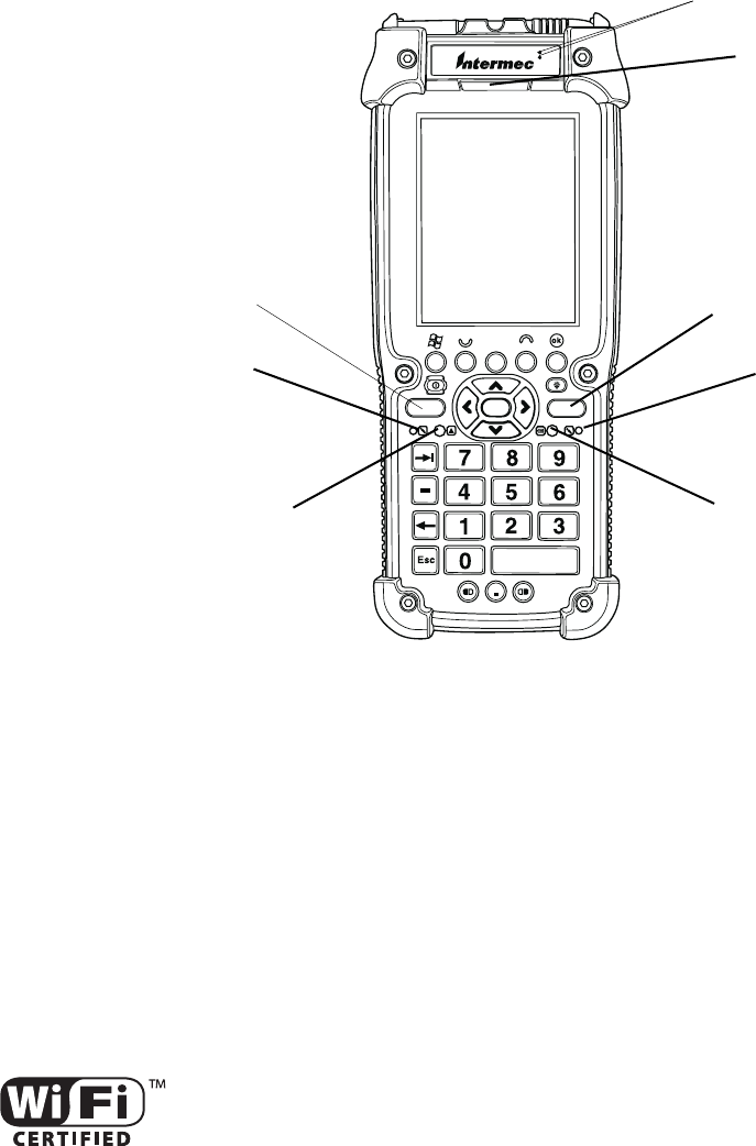
Enter
Battery status
Microphone
Microphone
Scan button
Intermec Ready-To-Work
Good read light
Indicator
Front Speaker
Scan button
Keyboard function
Chapter 1 — Using the CK60 Handheld Computer
CK60 Handheld Computer with Windows CE User’s Manual 3
Learning Software Build Versions
The Persistent Storage Manager (PSM) is an area of storage which is
embedded in a section of the system’s FLASH memory. This storage area is
not erased when a cold-boot is performed. It may, however, be erased dur-
ing the reflashing process. In addition to storing applications and data files,
you do have the option to store a persistent registry to the PSM region.
Resetting Your CK60 Computer
You seldom need to perform a warm-boot or a cold-boot on the CK60
Computer. The CK60 Computer currently uses the configuration currently
saved in flash memory during the boot process.
In some cases where the CK60 Computer completely stops responding, an
application is locked up and does not respond, when you upgrade the firm-
ware, or when you reflash the CK60 Computer, it may be necessary to per-
form either a warm-boot or a cold-boot.
Performing a Warm-Boot on the CK60 Computer
If your charged CK60 Computer does not resume after pressing I, or if the
computer or an application is locked up, you may need to do a warm-boot.
•Press and hold I for ten seconds. The CK60 Computer tells you it is
performing a warm-boot, then comes back up to the start screen.
Performing a Cold-Boot on the CK60 Computer
If the CK60 Computer or an application is locked up and does not respond
to a warm-boot, do the following.
1Release the lower clip of the hand strap.
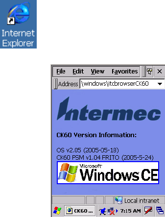
To check to see if your CK60 Computer has the latest PSM build or the
latest operating system build, double-tap the Internet Explorer icon from
the desktop, then scroll down for the latest information displayed beneath
the CK60 Version Information title.
Chapter 1 — Using the CK60 Handheld Computer
4 CK60 Handheld Computer with Windows CE User’s Manual
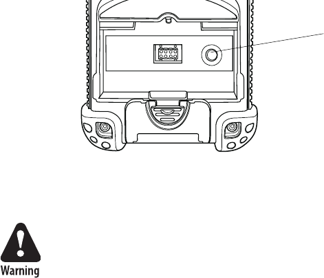
2Remove the battery pack.
3Press the reset button (shown in the following illustration).
4Reinstall the battery pack.
Scanning Bar Codes
Use the scanner to scan and enter bar code data. The type of scanner you
are using and the type of bar code you are decoding determines the way you
scan the bar code. The CK60 Computer supports the scanning of 2D
images. Plus, if you are using an integrated handle or a tethered scanner, the
way you scan bar codes is different.
When you unpack the CK60 Computer, these bar code symbologies are
enabled:
•Code39
•UPC/EAN
• PDF417 (if supported)
If you are using bar code labels that are encoded in a different symbology,
you need to enable the symbology on the computer.
Scanning with the 2D Area Imager
The CK60 Computer has the 2D area imager, which provides the ability to
scan 2D bar code symbologies and supports omni-directional (360°) scan-
ning where you can position the CK60 Computer in any orientation to
scan a bar code label. Using the 2D area imager is very similar to taking a
picture with a digital camera.
Do not look directly into the window area or at a reflection of the laser
beam while the laser is scanning. Long-term exposure to the laser beam
can damage your vision.
Avertissement: Ne regardez pas directement la réflexion d’un rayon
laser ou dans la fenêtre du laser lorsque celui-ci est en opération. Si
vous regardez trop longtemps un rayon laser, cela peut endommager
votre vue.
Press this reset button with your stylus.
Do not use force or a sharp object
when pressing the reset button. You
may damage the reset button.
Chapter 1 — Using the CK60 Handheld Computer
CK60 Handheld Computer with Windows CE User’s Manual 5
To scan a bar code label with the 2D area imager
1Press I to turn on the CK60 Computer.
2Point the scanner window at the bar code label and hold the CK60
Computer steady a few inches from the label.
3Press the Scan button on the keypad or pull the trigger on a handle and
center the red aiming beam over the bar code label.
The aiming beam is smaller when the imager is closer to the bar code and
larger when it is further away.
When the CK60 Computer successfully reads a bar code label, you hear
a high beep and the green Good Read light turns on briefly.
4Release the Scan button.
Supported Devices
The CK60 Computer should connect the following scanner models: 1551,
1553, 1555; ScanPlus 1800SR, 1800ST, 1800VT; Scan Image 1470; SR1
and SG1, SF51. There are a number of different scan engines covered by
these models, including RFID and XLR scan engines. Model 1555 and
Scan Image 1470 are supported as input devices only; configuration of
these models are accomplished by scanning labels.
Using the Ambient Light Sensor
The ambient light sensor automatically turns off the display lighting as sur-
rounding light increases to conserve your CK60 Computer battery power.
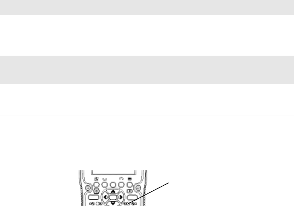
As configured from the factory, the ambient light sensor is disabled. To
enable the ambient light sensor and change its settings, tap Start > Settings
> Control Panel. Double-tap the Backlight icon, then tap the right arrow
to scroll to and tap the Both Power tab. Make your selections, then tap OK
to exit this applet.
This assumes the backlight setting once the CK60
Computer is powered on.
This turns off the ambient light sensor.
With this, the backlight is disabled in normal environments.
With this, the backlight is disabled in bright environments.

Chapter 1 — Using the CK60 Handheld Computer
6 CK60 Handheld Computer with Windows CE User’s Manual
Using the Battery
The CK60 Computer uses a 17.3 Watt-hour, 7.2V, replaceable Lithium-
Ion (LiIon) battery. You must fully charge the main battery before you can
use the CK60 Computer. When you change the battery, a backup battery
(super capacity) maintains your status, memory, and real-time clock for at
least 10 minutes.
Dispose of used battery packs promptly. Keep away from children. Contact
your Intermec representative for replacement batteries.
Several factors determine the life of your battery such as extreme tempera-
tures, input devices, and your usage. For example, if you use a tethered
scanner every day, you need to replace your battery more often than some-
one who uses an internal scanner.
The CK60 Computer contains an internal super capacitor, a temporary
power storage device, that protects state for up to ten minutes. This is to
give you time to replace the main battery pack before state is lost. Be sure to
put the computer in a suspend mode before doing so.
You can configure the battery power fail level so that after the system shuts
down in a low battery condition, there is still sufficient charge to allow the
unit to remain configured, keep proper time, and maintain DRAM
(Dynamic Random Access Memory) for at least ten minutes at room tem-
perature if the main battery remains in the handheld computer, using the
Power control panel applet (see page 8). The state and time are lost if:
• The battery discharges beyond this level.
• The battery is removed when the computer is not in suspend mode.
Changing and Installing the Battery
Make sure you fully charge the LiIon battery before you install it in your
CK60 Computer; and that you take at least 20 minutes to initially charge
the backup battery before the backup system is fully functional.
The LiIon battery pack used in this device may present a fire or chemi-
cal burn hazard if it is mistreated. Do not disassemble it, heat it above
100°C (212°F) or incinerate it.
Avertissement: Le paquet de piles d’ions de lithium qui est utilisé dans
cet appareil peut presenter un risque feu ou un risque chimique de
brûlure s’il est maltraité. Il ne faut pas le désassembler, le réchauffer à
une température plus élevée que 100°C (212°F) ou l’incinérer.
If you fail to replace the battery immediately, you may lose important
state or applications.
Attention: Si la batterie n’est pas remplacée immédiatement, des don-
nées ou applications importantes risquent d’être perdues.
Chapter 1 — Using the CK60 Handheld Computer
CK60 Handheld Computer with Windows CE User’s Manual 7
To charge the battery
Either insert the battery into the CK60 Quad Battery Charger or place the
CK60 Computer with battery installed in a CK60 Single Dock, a CK60
Single Dock with modem, or a CK60 Multidock. The battery charge time
is four hours or less on any of these docks if the temperature is within the
battery charging range.
You could also use a CK60 Power Adapter to keep the CK60 Computer on
full power.
For maximum efficiency, store your CK60 Computer on external power
with which to charge your batteries.
For more information on these accessories, see “Accessories for the CK60
Computer” on page 17.
To install the battery, insert the tabs on the bottom of the charged battery
into the CK60 Computer and snap the battery into place.
Maximizing Battery Life
Below are things that you can do to maximize the life of your battery.
Checking the Battery Status
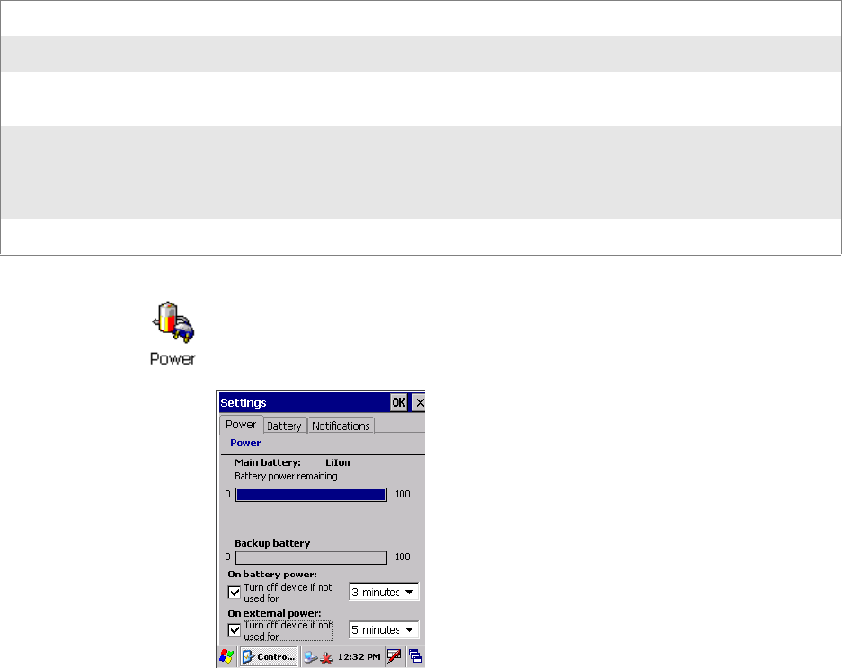
The battery status LED above your CK60 keypad, as shown in the follow-
ing illustration, indicates the status of your battery. See the table on the
next page to understand the meanings of the lights emitted from the LED.
Maximizing the Life of Your Battery
When You Want To: Do This to Save Battery Power:
Operate the CK60 Computer and the Low
Battery status icon appears or the Battery
light comes on.
1Press I to turn off the CK60 Computer.
2Remove the battery and insert another fully charged battery as
quickly as possible or you may lose state.
Or, you can insert the CK60 Computer into a powered quad battery
pack charger.
Stop using the CK60 Computer for five
minutes or longer.
1Make sure the low battery icon is not on the screen and that the Bat-
tery light is not turned on.
2Press I to turn off the CK60 Computer.
Store the CK60 Computer for more than a
day.
1Save your state and end your computer session.
2Press I to turn off the CK60 Computer.
3Insert a fully charged battery.
Battery status LED
Chapter 1 — Using the CK60 Handheld Computer
8 CK60 Handheld Computer with Windows CE User’s Manual
Using the Keypad
Your CK60 Computer has one of the following keypad overlay options:
• 32-key DSD large numeric
• 45-key full alphanumeric
• 58-key full alphanumeric
Steady Green Battery is more than 95% charged and unit is on a charger.
Blinking Red Battery is low.
Steady Red Main battery is low, or if charging, remains red until your CK60 Computer reaches 95%
charge status.
Steady Yellow Your CK60 Computer is on a charging source and there is no battery pack installed. Can
also mean that your CK60 Computer is out of charging range 32
°
to 122
°
F (0
°
to 50
°
C).
Once your CK60 Computer gets back in range, charging resumes and the LED changes to
red or green.
Steady Amber Replace the battery pack.
You can also use the Power control panel applet to view the status of this
battery. Tap Start > Settings > Control Panel. Double-tap the Power icon,
then tap the Power tab. Tap OK to exit this applet.
Chapter 1 — Using the CK60 Handheld Computer
CK60 Handheld Computer with Windows CE User’s Manual 9
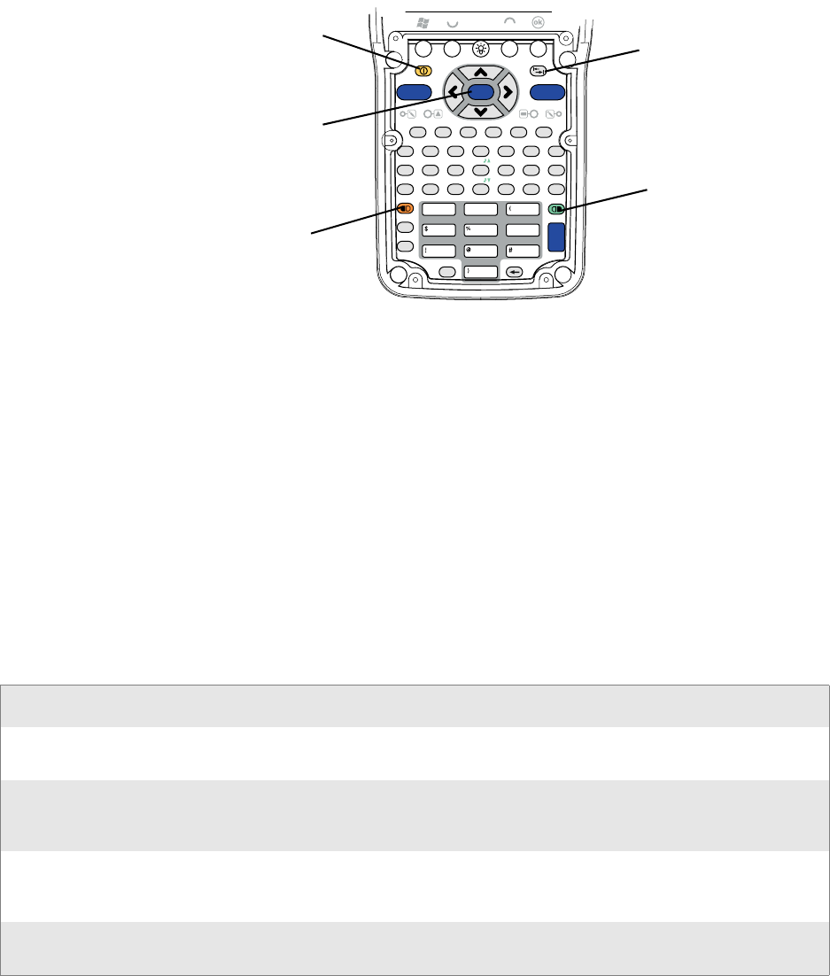
32-Key Large Numeric Keypad
The 32-key keypad is for applications that enter mainly numeri data (0-9).
This keypad also lets you enter special characters by pressing color-coded
key sequences.
45-Key Full Alphanumeric Keypad
This keypad is for applications that enter mainly numeric data (0-9) and
that may need to enter the entire alphabet. This keypad also provides
shirted function keys (F1-F12) and special characters, symbols, and func-
tions by pressing color-coded key sequences.
8
5
79
46
3
2
1
0.
-
Esc Enter
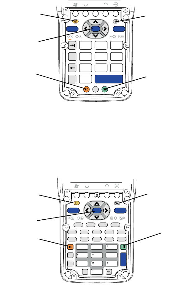
Backlight key
Green key
Orange key
Scan key
Power key
RollPage
F1 F2 F3 F4F5 F6 F7 F8
45
789
6
&*
^
Esc
Space
0
123
.
,Sp
CAPS
Help Home NewLnOP Q
S
Print
T?U
R
W
VFld EOF
X
Z
Y
Del
Reset
+
-
Fld -
=
F1 F2 F3 F4
F5 F6 F7 F8
F11 F12
F9
F10
APA1 PA2 PA3 AutLg
Attn
BC D
EFClear Dup
FMark SysRq
Clr Fld X
Hex
GH I
JKLMN
Ins
+
Shift
CTRL
Enter
Backlight key
Green key
Orange key
Power key
Scan key
Chapter 1 — Using the CK60 Handheld Computer
10 CK60 Handheld Computer with Windows CE User’s Manual
58-Key Full Alphanumeric Keypad
This keypad is for applications that enter mainly numeric data (0-9) and
that may need to enter the entire alphabet. This keypad also provides shift
function keys (F1-F24) and special characters, symbols, and functions by
pressing color-coded key sequences.
Using the Color-Coded Keys
Each keypad available for the CK60 Computer provides color-coded keys
to let you access additional characters, symbols, and functions printed on
the keypad overlay. Once you understand how to use the color-coded keys
and key sequences, you will know how to access all of the additional fea-
tures printed on the keypad overlay. There are two color-coded modifier
keys on the CK60 Computer: the orange B key and the green C key.
You press and release the first key, then press and release the second key to
access the color-coded character or function printed above a key. Note that
there are several hidden characters (such as < or >) on each CK60 keypad
that require using the color-coded keys to access them.
Using the Color-Coded Keys
You Wan t To: Press: Example
Use an orange character or func-
tion printed above a key.
B key, then the key with the charac-
ter or function printed above it.
Press B, then F7 to type the M char-
acter on the 45-key keypad.
Use a green character or function
printed above a key.
C key, then the key with the charac-
ter or function printed above it.
Press C, then Y to print the greater
than symbol (>) on the 58-key key-
pad..
Lock the orange, green, Ctl, Alt,
or Shift key to stay on.
B, C, Ctl, A.t, or Shift key twice. Press C twice and the applicable icon
appears in the status bar with a pad-
lock.
Unlock a green, orange, Ctl, Alt,
or Shift key.
B, C, Ctl, Alt, or Shift key once.
Enter
12
0
3
456
789
&*
^
CBADEF
GJIHKLM
NQP
OR
X
ST
Z
UWVY
Esc
Space
Shift
CTRL
Sym
Ins Home
Help
Fld - EOF
Fld +
AutoLg
Menu
+-
=
[
]
_'"
~
|
.
Attn
Hex
Print Reset SReq
FMark
NewLn
Clr Clear Dup Erase Fld X
CAPS
PA1 PA2 PA3
{
`
}
;:<>/\
F9 F10 F11 F12 F13 F14
F15 F16 F17 F18 F19 F20 F21
F22 F23 F24
Del
RollPage
F1 F2 F3 F4F5 F6 F7 F8
Backlight key
Green key
Orange key
Scan key
Power key
Chapter 1 — Using the CK60 Handheld Computer
CK60 Handheld Computer with Windows CE User’s Manual 11
Capitalizing All Characters
To type all alphanumeric characters as uppercase letters, you can enable the
Caps Lock feature on the CK60 keypad.
To enable Caps Lock, press the applicable sequence:
• On the 45-key keypad, press the C key, then the Esc key.
• On the 58-key keypad, press the B key, then the Space key.
To disable Caps Lock, press the same key sequence you used to enable it.
Typing Alphabetical Characters on the 45-Key Keypad
On the 45-key keypad, press the orange B key, then the applicable key to
enter letters of the alphabet when necessary.
Using the Power (I) Key
When you press the I key to turn off the CK60 Computer, you actually
put the CK60 Computer in Suspend mode. In Suspend mode, the CK60
Computer continues to supply power to all memory, but turns off power to
most hardware. This power-saving feature is to prolong battery life.
When you press the I key to turn the CK60 Computer back on, your com-
puter resumes where it was when you turned it off.
If you are using WPA or 802.1x security, the computer may need to reau-
thenticate before it starts your application.
If the Battery light flashes and the CK60 does not resume after pressing I,
your battery may be too low to supply power. Replace the battery.
Turning on the Keypad Backlight
You can configure your keypad to turn on a backlight to assist you when
you are working in low lighting. To adjust the backlight for the keypad, tap
Start > Settings > Control Panel, then double-tap the Backlight icon. Tap
the right arrow to move to and tap the Keyboard tab. Make your selection,
then tap OK to exit this applet.
Chapter 1 — Using the CK60 Handheld Computer
12 CK60 Handheld Computer with Windows CE User’s Manual
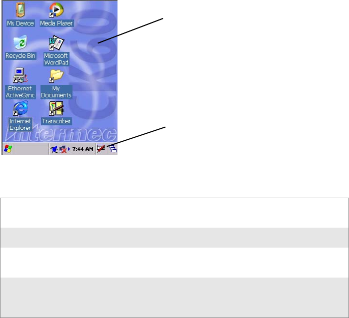
Using the Screen
The CK60 Computer has a 3.8” diagonal, 240x320 pixel (QVGA) trans-
flective TFT-LCD 64K color display. The screens support Unicode charac-
ters, user-programmable fonts, and bitmap graphics. The Start screen has
two distinct areas: the desktop and the taskbar. The desktop displays short-
cuts to some of the applications installed on the CK60 Computer. The
taskbar displays the Start menu, the time, the onscreen keyboard icon, and
the desktop icon.
Your CK60 Computer has a stylus for selecting items and entering infor-
mation. Use the stylus in place of a mouse.
Tap Touch the screen once with the stylus to select options, close appli-
cations, or launch menus from the taskbar.
Double-tap Touch the screen twice with the stylus to launch applications.
Drag Hold the stylus on the screen and drag across the screen to select
text and images.
Tap a nd h old Tap and hold the stylus on an icon to see a list of actions available
for the item. On the pop-up menu that appears, tap the action you
want to perform.
Desktop
Taskbar
Chapter 1 — Using the CK60 Handheld Computer
CK60 Handheld Computer with Windows CE User’s Manual 13
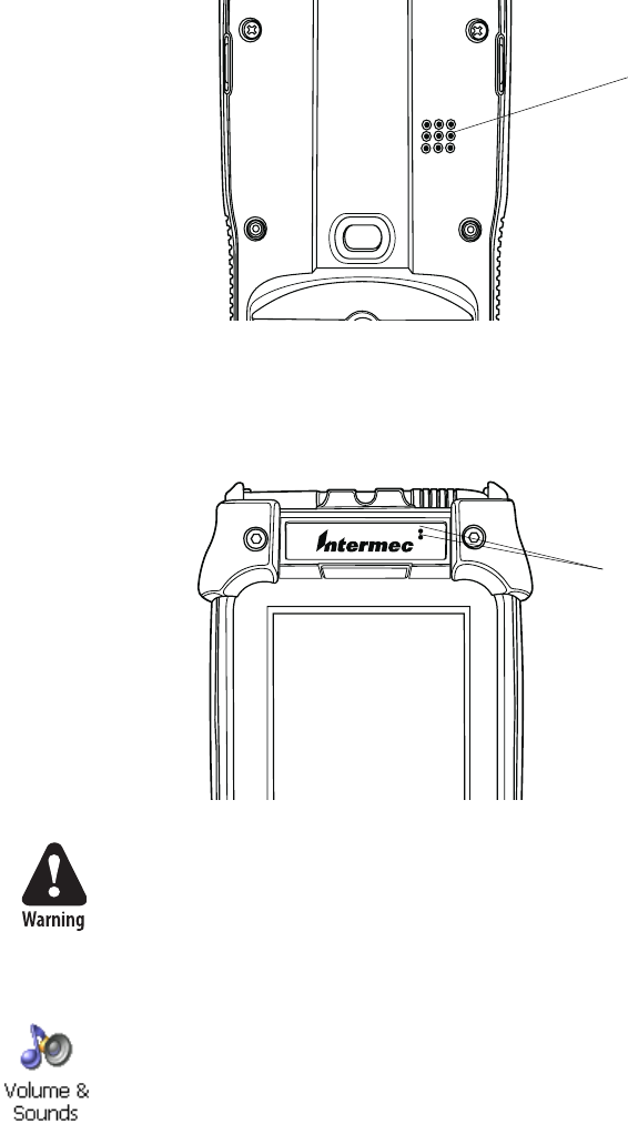
Using the Speakers
The high-volume speaker on the back of the CK60 Computer, is capable of
variable volume levels. This speaker is capable of reproducing voice and
WAV files, and is used primarily to convey status tones. There is a separate
volume control in the Volume & Sounds control panel applet. Information
on this applet is below and on the next page.
The front speaker is a full-voice range speaker of cell-phone quality with a
separate volume control. See the next page for information about this vol-
ume control.
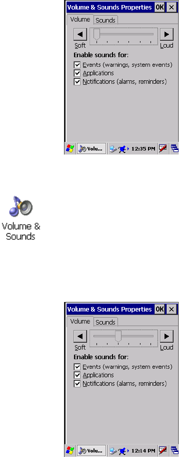
Enabling the Speaker and Adjusting the Volume
2Drag the slider bar to the right to the “Soft” position.
Warning: Do not place the speaker next to your ear when the speaker
volume is set to “Loud” (maximum), or you may damage your hearing.
To enable the speaker and adjust the volume:
1Tap Start > Settings > Control Panel. Double-tap the Volume &
Sounds icon, then tap the Volume tab.
High-volume speaker on center, back
of CK60 Computer
Front Speaker
Chapter 1 — Using the CK60 Handheld Computer
14 CK60 Handheld Computer with Windows CE User’s Manual
3Tap OK to exit this applet.
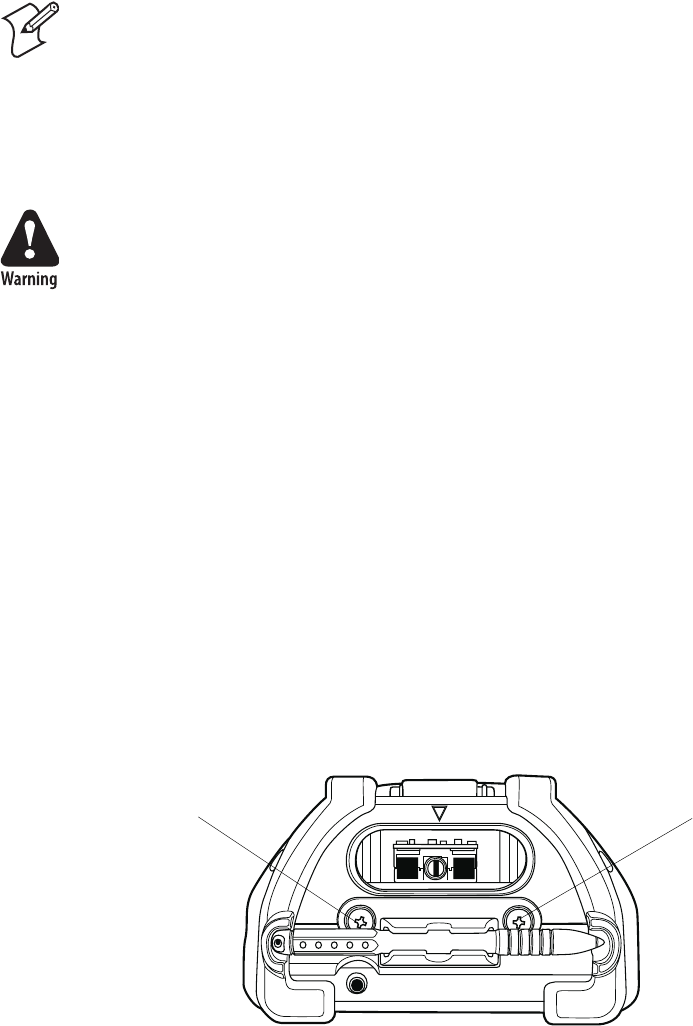
Disabling the Speaker
2Tap the Soft button to drag the slider all the way to the left.
3Tap OK to exit this applet.
Using the Status Lights
The status lights on the CK60 Computer turn on to indicate the status of
the battery or a successful decode of a bar code.
The battery lights and the battery screen icon work with each other to alert
you to the status of your battery. If the battery light (to the right of the
Scan button) comes on, check the status bar to see which battery icon
appears on it. The battery may be critically low and need replacing.
The Good Read light (green) above the display indicates when the CK60
Computer successfully decodes a bar code.
To disable the speaker:
1Tap Start > Settings > Control Panel. Double-tap the Volume &
Sounds icon, then tap the Volume tab.
Chapter 1 — Using the CK60 Handheld Computer
CK60 Handheld Computer with Windows CE User’s Manual 15
Using the Secure Digital Card
You can use a Secure Digital (SD) card to increase file storage and install
software. The CK60 Computer currently supports SanDisk SD cards only.
The SD card slot is located on the top of the CK60 Computer just above
the scanner window.
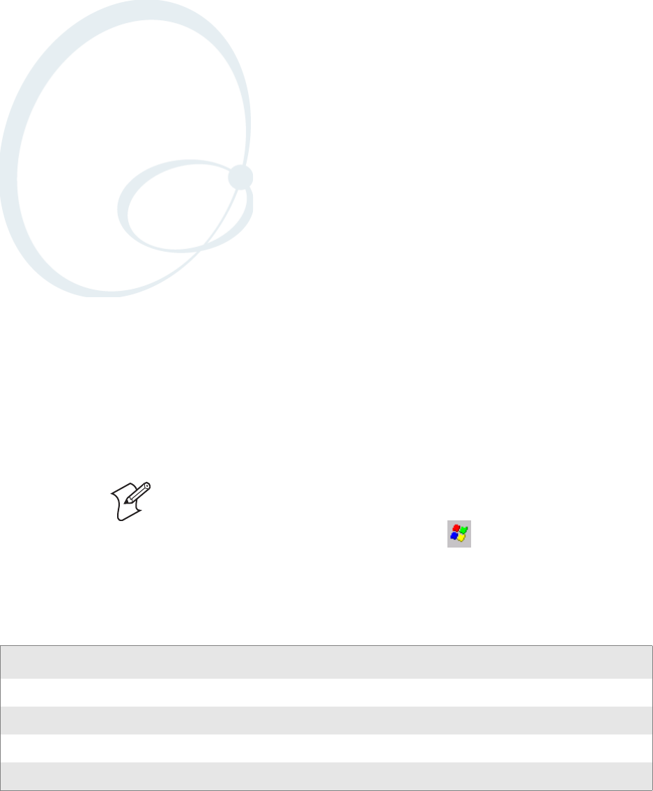
To insert an SD card:
1Press I to turn off the CK60 Computer.
2Remove the two screws on the SD card slot door and remove the door
(see illustration on the next page). Note that the screws to this door are to
be torqued to 1.5 in-lbs.
3Gently insert the SD card into the CK60 Computer with the printed
side facing the keypad and screen side of the CK60 Computer.
4Push the card into the slot until it latches in place and the steel card
retainer covers the end of the SD card.
5To replace the door, insert the door catch into the slot above the steel
card retainer.
6Replace the two screws.
7Press I to turn on the CK60 Computer.
To remove the SD card:
1Press I to turn off the CK60 Computer.
2Remove the two screws on the SD card slot door and remove the door.
Note that the screws to this door are to be torqued to 1.5 in-lbs.
Note: MultiMediaCards (MMCs) and CompactFlash (CF) storage cards
are not supported in the CK60 Computer.
Warning: You can corrupt your SD card if you do not follow these
installation and removal procedures exactly.
Screw Screw

Chapter 1 — Using the CK60 Handheld Computer
16 CK60 Handheld Computer with Windows CE User’s Manual
3Push in on the SD card until you hear it unlatch. The card should eject
far enough that you can easily remove it from the CK60 Computer.
If the card does not eject easily, you can use the door catch to remove it
by turn the door upside down and using the catch to pull out the SD
card.
4Remove the SD card from the CK60 Computer.
Physical and Environmental Specifications
Use this section to locate technical information about the CK60 Computer
and its available features and options.
Physical Dimensions
Length: 22.5 cm (8.87 in)
Width: 9.3 cm (3.68 in)
Depth: 5.0 cm (1.98 in) with standard case
Weight: 563 g to 852 g depending on configuration
(23 oz to 30 oz)
Power Specifications
Operating: Rechargeable 17.6 W LiIon battery pack
Backup: Super Capacity supplies 10 minutes bridge
time while replacing the main battery
Electrical Specifications
Model: CK60
External Charge Power: 11 to 28 VDC @ 1.5 A max. (18 W max.)
Temperature and Humidity Specifications
Operating temperature: -20° to 50°C (-4° to 122°F)
Operating humidity: 95% noncondensing
Storage temperature: -20° to 50°C (-4° to 122°F)
Storage humidity: 95% relative humidity, noncondensing
Screen Specifications
• 240x320 pixels
• 9.7 cm (3.8 in) diagonal active area
• 5-level LED backlight control with high and low settings
Warning: Before installing an SD card, inspect the gasket on the door
for any damage or wear, and replace the door if any damage or wear is
found.
Chapter 1 — Using the CK60 Handheld Computer
CK60 Handheld Computer with Windows CE User’s Manual 17
Keypad Options
32-key DSD large numeric keypad
45-key large alphanumeric keypad
58-key alphanumeric keypad
Bar Code Symbologies
Codabar, Codablock A, Codablock F, Code 11, Code 2 of 5, Code 39,
Code 93, Code 128, Interleaved 2 of 5, Matrix 2 of 5, Micro PDF417,
MSI, PDF417, Plessey, RSS 14, RSS Expanded, RSS Limited, Telepen,
UPC/EAN
Accessories for the CK60 Computer
You can use these accessories (sold and ordered separately) with the CK60
Computer. To order accessories, contact your local Intermec representative.
CK60 Quad Battery Charger
Use the Quad Battery Charger to charge up to four batteries without hav-
ing to remove them from the CK60 Computer. You can insert up to four
CK60 Computers with batteries installed making it easy to remember to
charge your batteries overnight. The charger also provides power to your
CK60 Computers while communicating via Ethernet.
CK60 Ethernet Multidock
Use the CK60 Ethernet Multidock to hold up to four CK60 Computers
with a batteries installed. The multidock charges the batteries, provides
power to the CK60 Computers, provides one Ethernet connector, and pro-
vides a serial port for each inserted CK60 Computer.
CK60 Single Dock
Use the CK60 Single Dock to hold a CK60 Computer with its battery
installed. The single dock charges the battery, provides power to the CK60
Computer, provides an Ethernet connector, and provides a serial port for
the inserted CK60 Computer.
CK60 Single Dock with Modem
Use the CK60 Single Dock with Modem to hold a CK60 Computer with
its battery installed. The single dock charges the battery, provides power to
the CK60 Computer, provides an Ethernet connector, and provides a serial
port for the inserted CK60 Computer.
CK60 Holster and Belt
Use the holster and belt to carry your CK60 Computer while not using it.
The holster and belt support either right- or left-handed use and you can
use it to carry a CK60 Computer with or without a handle. You can only
use this with a CK60 Computer that has either the 1D linear imager or the
2D imager.
Chapter 1 — Using the CK60 Handheld Computer
18 CK60 Handheld Computer with Windows CE User’s Manual
CK60 Handstrap
The removable and adjustable handstrap make it easy for you to hold and
use the CK60 Computer without tiring your hand.
CK60 Power Adapter, USB Adapter, and Snap-On Adapters
Provides power to all of the docks and chargers.
CK60 Handheld Computer with Windows CE User’s Manual 19
2Windows CE
This chapter introduces Microsoftr Windowsr CE 5.0. While using your
CK60 Handheld Computer, keep this key point in mind:
Tap Start on the task bar, located at the bottom, left corner of the screen, to
quickly move to programs, files, and settings. Use the task bar at the bot-
tom of the screen to perform tasks in programs. The task bar includes
menus, buttons, and the onscreen keyboard.
This chapter describes your CK60 Computer Windows CE applications,
and explains how to connect your CK60 Computer to a PC, a network, or
the Internet. Below is a guide to assist you in using your CK60 Computer.
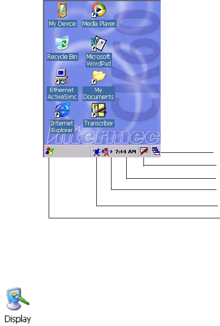
Note: Desktop icons and control panel applet icons are shown to the left.
Any place that Start is mentioned, tap the following Windows icon in the
bottom, left corner of your CK60 desktop.
For information on: See this source:
Programs on your handheld computer. This chapter.
Connecting to and synchronizing with a PC. The Quick Start Guide or ActiveSync Help on your PC.
Last-minute updates, detailed technical information. Read Me files in the Microsoft ActiveSync folder on the PC.
Up-to-date information on Windows CE device. www.microsoft.com/windows/embedded/ce.net/default.asp
Chapter 2 — Windows CE
20 CK60 Handheld Computer with Windows CE User’s Manual
Basic Skills
Learning to use your CK60 Computer is easy. This section describes the
basic concepts of using and customizing your CK60 Computer.
Desktop Screen
When you turn on your CK60 Computer for the first time each day, you
see the Desktop screen.
Status icons display information such as low batteries or when the CK60
Computer is connected to a PC or to the Internet. You can tap an icon to
open the associated setting or program.
Programs
You can switch from one program to another by selecting it from the Start
menu. To access some programs, tap Start > Programs, and then the pro-
gram name.
To customize what is displayed on the Desktop screen, including the back-
ground image, tap Start > Settings > Control Panel, then double-tap the
Display icon.
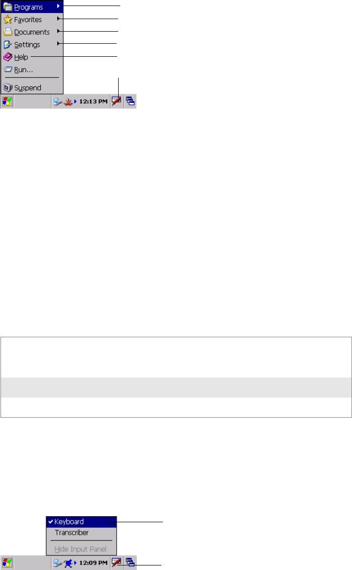
Tap to list open windows
Tap to activate the input panel
Double-tap to change time format
Tap to scroll to other programs
Tap to open an associated program
Tap to bring up the Start menu
Chapter 2 — Windows CE
CK60 Handheld Computer with Windows CE User’s Manual 21
Start Menu and Task Bar
The Start Menu is located at the bottom of the screen. It displays the active
program, and allows you to switch to programs and close screens.
The task bar, which displays the current time, is at the bottom of the
screen. The task bar includes menu names, buttons, and the Input Panel
icon. Use this task bar to perform tasks in programs.
Notifications
Your device can notify you in any of the following notification types:
• A message box appears on the screen.
• A sound, which you can specify, is played.
• A light flashes on your CK60 Computer.
Entering Information
You can enter information on your CK60 Computer in several ways,
depending on the type of device you have and the program you are using:
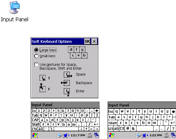
Use the input panel to enter information in any program on your CK60
Computer. You can either type using the onscreen keyboard or write using
Tr a n s c r i b e r (described on page 22). The characters appear as typed text.
To show the input panel, tap the Input Panel icon, then tap Keyboard. To
hide the input panel, tap the Keyboard icon, then tap Hide Input Panel.
Typing Using the input panel, enter typed text into the CK60 Computer. You can
do this by tapping keys on the onscreen keyboard or by using handwriting
recognition software.
Writing Using the stylus, write directly on the screen.
Drawing Using the stylus, draw directly on the screen.
Tap to see more programs
Tap to see websites
Tap to see text files and other documents
Tap to configure your unit
Tap to display the input panel
Tap to learn more about an application
Input Panel icon
Select an input method
Chapter 2 — Windows CE
22 CK60 Handheld Computer with Windows CE User’s Manual
Large Keys Versus Small Keys on Keyboard
Typing With the Onscreen Keyboard
Tap the stylus input icon, then tap Keyboard. On the soft keyboard that is
displayed, tap the keys with your stylus.
• To type lowercase letters, tap the keys with the stylus.
• To type a single uppercase letter or symbol, tap the Shift key. To tap
multiple uppercase letters or symbols, tap the CAP key. Note that the
CAP key only appears when the keyboard is set to small keys. See previous
page for information about the keys.
• To convert a letter to uppercase, tap and hold the stylus on the letter and
drag up.
• To add a space, drag the stylus to the right across at least two keys.
• To backspace, drag the stylus to the left across at least two keys.
• To insert a carriage return, tap and hold the stylus on the keyboard and
drag down.
Using Transcriber
With Transcriber, you can write on the screen with the stylus just as you
would on paper. You can write a sentence or more of information, then
pause and let Transcriber change written characters to typed characters.
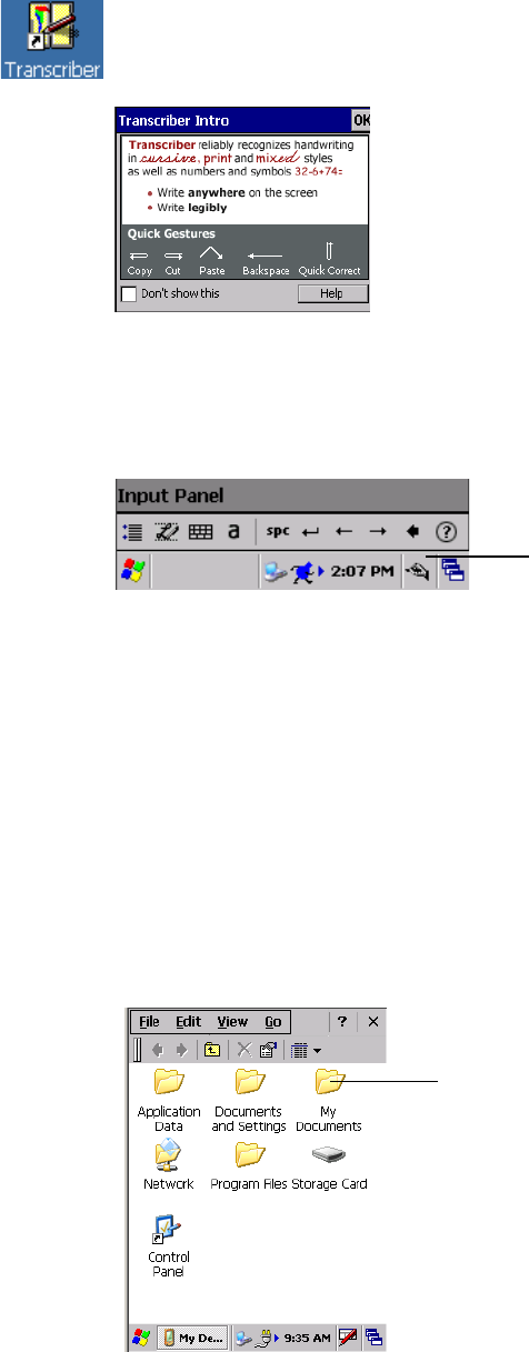
The default setting for the keyboard is with small keys. If you want to use
larger keys, tap Start > Settings > Control Panel, then double-tap the
Input Panel icon. Tap Options, then select Large keys. Tap OK, then OK
again to close the Input Panel properties. Below are the keyboards.
Keyboard with small keys Keyboard with large keys
Chapter 2 — Windows CE
CK60 Handheld Computer with Windows CE User’s Manual 23
To enable the Transcriber, tap the Input Panel icon on the task bar, select
Tr a n s c r i b e r, tap OK to close the Transcriber Intro, select an option, then
write anywhere on the screen for the input to appear in the active window.
Tap the Tr a n s c ri b e r icon, then select Hide Input Panel, to disable.
Selecting Typed Text
If you want to edit or format typed text, you must select it first by dragging
the stylus across the text.
You can cut, copy, and paste text by tapping and holding the selected words
and then tapping an editing command on the pop-up menu, or by tapping
the command on the Edit menu.
Finding and Organizing Information
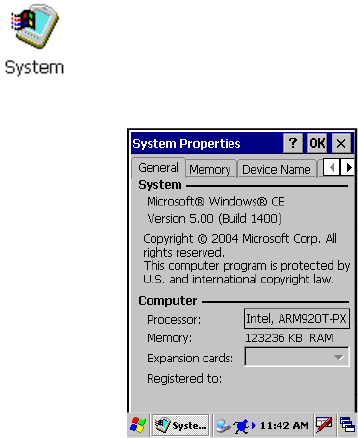
You can use the Windows Explorer to find files on your CK60 Computer
and to organize these files into folders. Tap Start > Programs > Windows
Explorer.
For specific instructions on using Transcriber, double-tap the Tr a n s c r i b e r
shortcut on the desktop screen or tap the Tr a n s c r i b e r option in the Input
Panel menu, then tap Help. Tap OK to close the Transcriber Intro box.
Transcriber icon
Double-tap a folder to open it.
Chapter 2 — Windows CE
24 CK60 Handheld Computer with Windows CE User’s Manual
Customizing Your CK60 Computer
You can customize your CK60 Computer by adjusting settings and install-
ing additional software.
Programs added to your CK60 Computer at the factory are stored in ROM
(Read Only Memory). You cannot remove this software, and you cannot
accidentally lose ROM contents.
You can install any program created for your CK60 Computer, as long as
your CK60 Computer has enough memory. The most popular place to
find software for your CK60 Computer is on the Windows CE web site.
Adding Programs Using Microsoft ActiveSync
Install software developed for the CK60 Computer onto your PC before
installing the same software onto your CK60 Computer. Once installation
is complete, tap Start > Programs, then the program icon to switch to it.
2Download the program to your PC (or insert the CD or disk that con-
tains the program into your PC). You may see a single *.EXE or *.ZIP
file, a SETUP.EXE file, or several files for different CK60 Computer
types and processors. Be sure to select the program designed for the Win-
dows CE and your CK60 Computer processor type.
3Read any installation instructions, Read Me files, or documentation that
comes with the program. Many programs provide instructions.
4Connect the CK60 Computer and PC, then double-click the *.EXE file.
• If the file is an installer, the installation wizard begins. Follow the
directions on the screen. Once the software is installed, the installer
automatically transfers the software to your CK60 Computer.
• If the file is not an installer, an error message stating that the program
is valid but it is designed for a different type of computer is displayed.
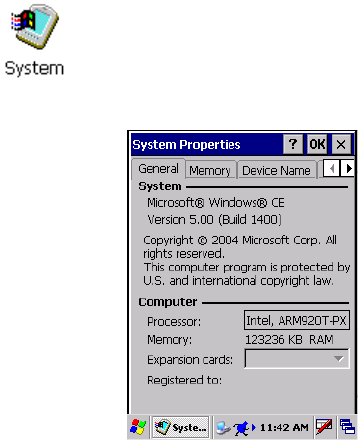
1Determine your CK60 Computer and processor type so that you know
which version of the software to install. Tap Start > Settings > Control
Panel, then double-tap the System icon. Note the processor information
on the General tab beneath the Computer heading.
Chapter 2 — Windows CE
CK60 Handheld Computer with Windows CE User’s Manual 25
Move this file to your CK60 Computer. If you cannot find any instal-
lation instructions for the program in the Read Me file or documenta-
tion, use Microsoft ActiveSync Explore to copy the program file to the
“My Computer\Program Files” folder on your CK60 Computer.
Adding a Program Directly from the Internet
Install the appropriate software for your CK60 Computer on your PC
before installing it on your CK60 Computer. Once installation is complete,
tap Start > Programs, then the program icon to switch to it.
2Download the program to your CK60 Computer straight from the
Internet using Internet Explorer. You may see a single *.EXE or *.ZIP
file, a SETUP.EXE file, or several versions of files for different CK60
Computer types and processors. Be sure to select the program designed
for the Windows CE and your CK60 Computer processor type.
3Read any installation instructions, Read Me files, or documentation that
comes with the program. Many programs provide instructions.
4Tap the file, such as *.EXE file to start the installation wizard. Follow the
directions on the screen.
Adding a Program to the Start Menu
You can either use Windows Explorer on the CK60 Computer to move the
program to the “\My Computer\Windows\Start Menu” folder, or use
Microsoft ActiveSync on the PC to create a shortcut to the program and
place the shortcut in the “\My Computer\Windows\Start Menu” folder.
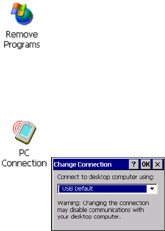
1Determine your CK60 Computer and processor type so that you know
which version of the software to install. Tap Start > Settings > Control
Panel, then double-tap the System icon. Note the processor information
on the General tab beneath the Computer heading.
Chapter 2 — Windows CE
26 CK60 Handheld Computer with Windows CE User’s Manual
Using Windows Explorer on the CK60 Computer
Tap Start >
Programs > Windows Explorer, and locate the program. Tap
and hold the program and tap Cut on the pop-up menu. Open the
“\My Computer\Windows\Start Menu” folder, tap and hold a blank area
of the window, and tap Paste on the pop-up menu. The program now
appears on the Start menu. For more information on using Windows
Explorer, see “Finding and Organizing Information” on page 23.
Using Microsoft ActiveSync on the PC
Use the Explore in Microsoft ActiveSync to explore your CK60 Computer
files and locate the program. Right-click the program, and then click Cre-
ate Shortcut. Move the shortcut to the “\My Computer\Windows\Start
Menu” folder. The shortcut now appears on the Start menu. For more
information, see ActiveSync Help.
Removing Programs
Microsoft ActiveSync
Visit the following Microsoft web site for the latest in updates, technical
information, and samples:
http://msdn.microsoft.com/embedded/downloads/ce/default.aspx
With Microsoft ActiveSync, you can back up and restore your CK60 Com-
puter data, and copy files between your CK60 Computer and your PC.
Install Microsoft ActiveSync on the desktop of your PC from the following
URL. For more information, on installing Microsoft ActiveSync, see your
Quick Start card. ActiveSync is already installed on your CK60 Computer.
http://msdn.microsoft.com/downloads/
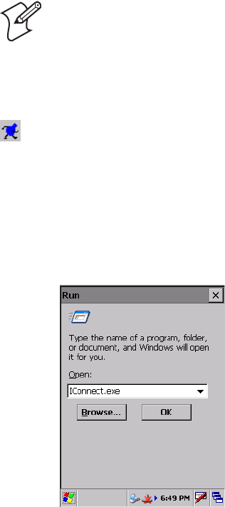
Tap Start > Settings > Control Panel, then double-tap the Remove Pro-
grams icon.
If the program does not appear in the list of installed programs, use Win-
dows Explorer on your CK60 Computer to locate the program, tap and
hold the program, and then tap Delete on the pop-up menu.
Tap Start > Settings > Control Panel, then double-tap the PC Connection
icon. Tap Change Connection, then select the baud rate from the list.
Chapter 2 — Windows CE
CK60 Handheld Computer with Windows CE User’s Manual 27
After installation is complete, the ActiveSync Setup Wizard helps you con-
nect your CK60 Computer to your PC or set up a partnership so you can
browse for or move data between your CK60 Computer and your PC.
Disconnect the CK60 Computer from your PC and you are ready to go!
IConnect
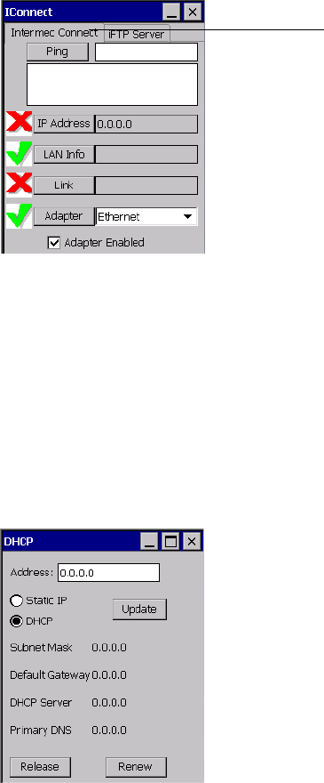
Note that once you exit the IConnect application, select Start > Run, enter
“IConnect.exe” in the Open field, then tap OK. The IConnect icon then reap-
pears in the system tray.
Note: While ActiveSync does synchronize files between your PC and your
CK60 Computer, the Windows CE operating system does not include Cal-
endar, Contacts, Tasks, Inbox, Channels, and Pocket Access applications.
The IConnect application displays information about the Ethernet adapter
and tests for connectivity. To access this application, tap the IConnect icon
in your system tray. Two options will appear in a pop-up menu, to either
open and or exit the application.
Chapter 2 — Windows CE
28 CK60 Handheld Computer with Windows CE User’s Manual
Internet Connection
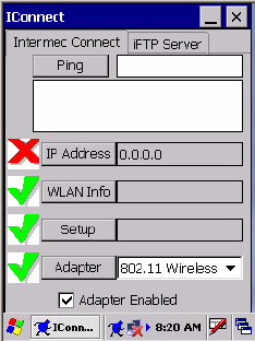
Tap Open IConnect to access the IConnect application.
Ethernet Connections
The following information applies to CK60 Computers using Ethernet:
IP Address
The IP Address row is for the current IP address. If the address is valid, a
green check mark appears to the left and the field contains the address. If
invalid, a red X is shown to the left. Tap IP Address to configure the IP set-
tings for the CK60 Computer and view other IP-related addresses.
The DHCP dialog contains information about the current IP address. You
can enter an IP address, check either Static IP or DHCP, then tap Update
to commit these changes. Tap Release or Renew near the bottom to either
release or renew changes to the DHCP address.
LAN Info
Tap LAN Info to access diagnostic pages.
Link
This row displays the current link speed if valid. A green check mark
appears to the left if the Ethernet cable is attached to the CK60 Computer.
A red X appears if the Ethernet cable is detached.
Tap this to test the connection
Chapter 2 — Windows CE
CK60 Handheld Computer with Windows CE User’s Manual 29
Adapter
This row lists the current network adapter. To change to a different
adapter, tap the drop-down arrow, select a different adapter, then check
Adapter Enabled below the drop-down list. To unload the current adapter,
clear (uncheck) Adapter Enabled.
For 802.11b/g Connections
The following information applies to CK60 Computers using 802.11
Wireless:
IP Address
The IP Address row is for the current IP address. If the address is valid, a
green check mark appears to the left and the field contains the address. If
invalid, a red X is shown to the left. Tap IP Address to configure the IP set-
tings for the CK60 Computer and view other IP-related addresses.
The DHCP dialog contains information about the current IP address. You
can enter an IP address, check either Static IP or DHCP, then tap Update
to commit these changes. Tap Release or Renew near the bottom to either
release or renew changes to the DHCP address.
WLAN Info
Tap WLAN Info to access diagnostic pages.
Setup
Tap Setup to configure the 802.11b/g SSID and security settings. See
“Configuring Security” on page 64 for more information.
Adapter
This row lists the current network adapter. To change to a different
adapter, tap the drop-down arrow, select a different adapter, then check
Adapter Enabled below the drop-down list. To unload the current adapter,
clear (uncheck) Adapter Enabled.

Chapter 2 — Windows CE
30 CK60 Handheld Computer with Windows CE User’s Manual
iFTP Server
Tap the iFTP Server tab to set up the FTP Server on the CK60 Computer.
Check or uncheck either option, tap Apply to change FTP Server settings.
Getting Connected
You can set up connections to the Internet and corporate network at work
to do such activities as browsing the Internet, sending and receiving e-mail
and instant messages, and synchronizing information using Microsoft
ActiveSync.
Connections can be made using a wired or wireless network. Once con-
nected to the Internet or to the network at your company or organization
where you work, you can view web pages by using Internet Explorer. The
communication software for creating an ISP connection is already installed
on your CK60 Computer. Your service provider may provide the software
needed to install other services, such as paging and fax services.
Connecting to an Internet Service Provider
You can connect to your ISP and use the connection to view web pages.
Get the following information from your ISP. Some ISPs require informa-
tion in front of the user name, such as “MSN/username.”
• ISP dial-up access telephone number
•User name
•Password
To view additional information for any screen in the wizard or while
changing settings, tap Help in the upper-right corner.

Chapter 2 — Windows CE
CK60 Handheld Computer with Windows CE User’s Manual 31
1Tap Start > Settings > Network and Dial-up Connections, then double-
tap Make New Connection.
2Enter a name for the connection, such as “My Connection,” then press
Next.
3In the Select a modem list, select “Hayes Compatible on COM1.” Tap
Next to continue.

Chapter 2 — Windows CE
32 CK60 Handheld Computer with Windows CE User’s Manual
4Enter the phone number, then tap Finish.
6Tap Dial Properties, then specify your current location from the drop-
down list.
Specify your current phone type. If your phone type is pulse dialing,
select Pulse dialing. If your type is tone dialing (as most phone lines are),
then select Tone dialing. Tap OK to close the Dialing Properties page.
These settings apply to all connections.
7To start the connection, start visiting web sites by using Internet
Explorer. See “Internet Explorer” on page 34 for information.
Direct Connection
A direct connection helps you to securely connect to servers, such as a cor-
porate network, via the Internet. Ask your network administrator for the
user name, password, domain name, TCP/IP settings, and host name or IP
address of the server.
5Double-tap the new ISP Connection icon, then enter the user name,
password, and domain (if provided by an ISP or your network adminis-
trator).
To view additional information for any screen in the wizard or while
changing settings, tap Help in the upper-right corner.

Chapter 2 — Windows CE
CK60 Handheld Computer with Windows CE User’s Manual 33
1Tap Start > Settings > Network and Dial-up Connections, then double-
tap Make New Connection.
2Enter a name for the connection, such as “Direct Connection.” Select
Direct Connection, then tap Next to continue.
3Select a device through which a connection is made from the Select a
device drop-down list, tap Configure to adjust the port settings, tap OK
to return to the Device screen, then tap Finish.
4Insert the necessary equipment into the device, then double-tap the new
Direct Connection icon to connect to the host.
5Use a desired program to automatically begin connecting. For example,
switch to Internet Explorer and browse to a web page.
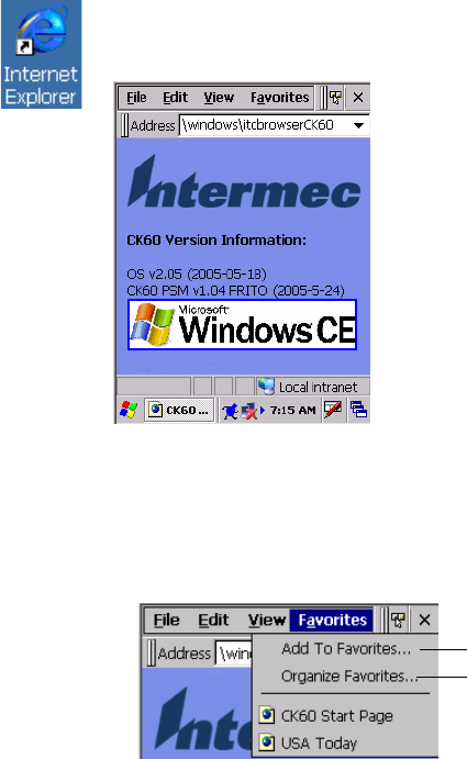
Chapter 2 — Windows CE
34 CK60 Handheld Computer with Windows CE User’s Manual
Ending a Connection
To disconnect, either detach your device when connected via cable or cra-
dle, or switch off the connection when connected via a wireless network.
Internet Explorer
Use Microsoft Internet Explorer to view web sites. To do this, create the
connection first via an ISP or network, as described in “Getting Con-
nected” on page 30.
When connected to an ISP or network, you can also download files and
programs from the Internet
Viewing Mobile Favorites and Channels
1Tap Favorites from the tool menu to display your list of favorites.
2Tap the page you want to view.
Browsing the Internet
1Set up a connection to your ISP or corporate network using information
as described in “Getting Connected” on page 30.
2To connect and start browsing, do one of the following:
•Tap Favorites from the toolbar, and then tap the favorite to view.
To switch to Internet Explorer on your CK60 Computer, double-tap the
Internet Explorer icon on your desktop.
Tap to add or delete a folder or a link
Tap the favorite you want to view
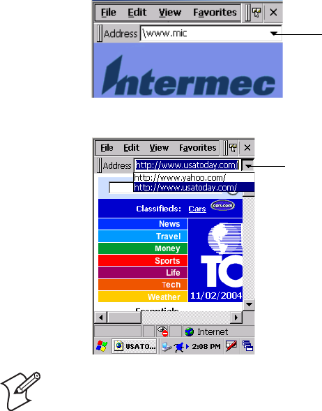
Chapter 2 — Windows CE
CK60 Handheld Computer with Windows CE User’s Manual 35
•In the Address bar that appears at the top of the screen, enter the web
address you want to visit using the input panel, then tap the [Enter]
key on the panel to go to that web site.
• Tap the drop-down arrow to select from previously entered addresses.
Note: To add a favorite link while using the CK60 Computer, go to the
page you want to add, then select Favorites > Add to Favorites.
Type the web address here
Tap for a list of addresses
Chapter 2 — Windows CE
36 CK60 Handheld Computer with Windows CE User’s Manual

CK60 Series Handheld Computer User’s Manual 37
3Configuring the CK60
Computer
Use this chapter to understand how to install applications onto your CK60
Series Handheld Computer and how to configure the CK60 Computer to
communicate in your network. In this chapter are these sections:
• Developing Applications for the CK60 Computer (page 38)
• Packaging Applications for the CK60 Computer (page 39)
• Installing Applications on the CK60 Computer (page 40)
• Converting Older Computer Applications to CK60 Applications (page
38)
• Configuring CK60 Parameters (page 49)
• Configuring the CK60 Computer for Your Network (page 53)
• Configuring the SF51 Scanner (page 61)
• Configuring Security (page 64)
• Using Configuration Parameters (page 90)
• Using Reader Commands (page 91)
Note: Desktop icons and control panel applet icons are shown to the left.
Any place that Start is mentioned, tap the following Windows icon in the
bottom, left corner of your CK60 desktop.
Chapter 3 — Configuring the CK60 Computer
38 CK60 Series Handheld Computer User’s Manual
Developing Applications for the CK60 Computer
CK60 Computers run applications programmed in Microsoft Embedded
Visual C++. Use this section to understand what you need to:
• Develop a new application for the CK60 Computer.
• Convert an application from an older computer to a CK60 application.
Use the Intermec SDK to develop new applications to run on the CK60
Computer. The Intermec SDK is a library of C++ language functions you
can use to create applications for the CK60 Computer.
See the SDK online user’s manual for help developing your application.
The Intermec CK60 SDK User’s Manual contains hardware and software
requirements, all of the functions that are supported by the CK60 Com-
puter, and how to use these functions.
The SDK is part of the Intermec Developer’s Library (IDL), which is avail-
able on the Intermec Developer’s Library CD or as a download from the
Intermec web site at www.intermec.com.
You need these hardware and software components to use the Intermec
SDK:
• Pentium PC, 400 MHz or higher
• Windows 2000 (Service Pack 2 or later) or Windows XP (Home, Profes-
sional, or Server)
• For native C++ development, Microsoft eMbedded Visual C++ version
4.0
•For Windows CD 5.0, eVC 4.0 SP4 is required
• 128 MB RAM (196 MB recommended)
• 360 MB hard drive space for minimum installation (720 MB for com-
plete)
• CD-ROM drive compatible with multimedia PC specification
• VGA or higher-resolution monitor (Super VGA recommended)
• Microsoft Mouse or compatible pointing device
Converting Older Computer Applications to CK60 Applications
If you have an existing application that you would like to run on the CK60
Computer, you can use the PSK to convert that application. The Intermec
PSK is a set of libraries and tools that you use to convert your existing C
applications into C++ applications for use on the CK60 Computer.
As you migrate from another computer to a CK60 Computer, you need to
consider when converting other computer applications to run on the CK60
Computer, most APIs should work without changes, with the exception
that arrow and tab keys may be reversed from other computers. Keyboard
Chapter 3 — Configuring the CK60 Computer
CK60 Series Handheld Computer User’s Manual 39
remapping is available on the CK60 Computer should you need to map
these keys like that of the other computer.
You need these hardware and software components to use the PSK:
• a PC with at least 1MB of free disk space running Microsoft Windows
2000 or Windows XP
• Microsoft eMbedded Visual C++ version 4.0 with Service Pack 2
• Intermec SDK and development tools
• Intermec PSK, which contains these files and utilities:
• PSK functions library
• Header files
• Example files
The PSK is part of the Intermec Developer’s Library (IDL), which is avail-
able on the Intermec Developer’s Library CD or as a download from the
Intermec web site at www.intermec.com.
Packaging Applications for the CK60 Computer
Use any of these methods to package applications for installation:
• You could package an application as a cabinet (CAB) file. Recommended
• For simple applications, the application itself may be the file to deliver.
• It could be a directory structure that contains the application, supporting
files like ActiveX controls, DLLs, images, sound files, and data files.
Consider any of the following when choosing a location into which to store
your application:
• In the basic CK60 Computer, there are two built-in storage options: the
Object Store and the Flash File Store. The Object Store is a Disk on
Chip (DOC) Flash that looks like a disk. The Flash File Store is an area
of storage which is embedded in a section of the system’s FLASH mem-
ory. This storage area is not erased during a cold-boot. It may, however,
be erased during the reflashing process. In addition to storing applica-
tions and data files, you do have the option to store a persistent registry
to the Flash File Store region.
• If the optional Secure Digital (SD) storage card is in the system, then
consider this card the primary location to place applications installation
files. The “\Storage Card” folder represents the SD card.
• Use the small non-volatile Flash File Store region to hold CAB files that
rebuild the system at cold-boot or install applications from a CAB file
into the Flash File Store so they are “ready-to-run” when a cold-boot is
performed. Since the FLASH in the system has a limited number of
write cycles, do not use the Flash File Store for excessive writing pur-
poses; however, reading is okay.
Chapter 3 — Configuring the CK60 Computer
40 CK60 Series Handheld Computer User’s Manual
CAB files (short form of “cabinet” files) are compressed folders as defined by
Microsoft. A “cabinet” file is a single file, usually suffixed with .CAB, that
stores compressed files in a file library. A compressed file can be spread over
several cabinet files. During installation, the setup application decompresses
the files stored in a cabinet and copies them to the user’s system. Intermec
recommends using CAB files to install your applications. The CK60 Com-
puter uses standard Windows CE CAB files and does install third-party
CAB files.
For the CK60 Computer, CAB files register DLLs, create shortcuts, modify
registry entries, and run custom setup programs. Tap a CAB file to extract
that file or place the CAB file on one of the approved storage devices in the
“\CabFiles” folder, then perform a warm-boot on the CK60 Computer.
There are two methods available to extract a CAB file:
• Tap a CAB file to extract it. With this method, the CAB file is automat-
ically deleted when the extraction process is successful, unless the CAB
file is set with the read-only attribute.
• Use the AUTOCAB method to extract all files when a cold-boot is per-
formed on the CK60 Computer. This method is on the Intermec Devel-
oper’s Library CD, see its Software Tools User’s Manual for information.
Installing Applications on the CK60 Computer
You can use either the Microsoft ActiveSync application or SD storage
cards to install applications on the CK60 Computer.
Installing Applications Using Microsoft ActiveSync
You can use Microsoft ActiveSync to establish a connection between your
PC and the CK60 Computer. Microsoft ActiveSync transfers files, synchro-
nizes files, performs remote debugging, and other device management
activities.
See Chapter 2, “Windows CE” for information about the Microsoft Active-
Sync application as provided by Microsoft Corporation.
This can be a serial, a USB, or an 802.11b/g Microsoft ActiveSync connec-
tion. Files can be copied using Windows Explorer on a PC or a laptop com-
puter. This is usually good when updating a few CK60 Computers.
These instructions assume that Microsoft ActiveSync was installed onto
your PC and is up and running. If not, go to Chapter 2, “Windows CE” for
an URL from which to download the latest application.
1Connect the CK60 Computer to a PC using a USB or serial cable. You
may have to detach, then reattach the cable to “wake” the connection.
2Wait for a “Connected” message to appear in the Microsoft ActiveSync
application to signal a connection to the CK60 Computer. If necessary,
select File > Get Connected to initiate a connection or detach, then reat-
tach the USB or serial cable.
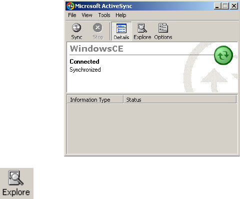
Chapter 3 — Configuring the CK60 Computer
CK60 Series Handheld Computer User’s Manual 41
5Within the “Mobile Device” folder, go to the folder where you want the
files located on the CK60 Computer, do a right-click for a pop-up
menu, then select Paste.
6When all of the files are pasted, perform a warm-boot on the CK60
Computer. When the computer reboots, wait for the LED on the top
left of your keypad to stop blinking. Tap Start > Programs > Windows
Explorer to locate the newly copied executable files, then tap these files
to activate their utilities.
Installing Applications Using a Secure Digital Card
If you have an SD card for your CK60 Computer, this is the best place for
you to install applications.
1If you are using an SD card reader, suspend the CK60 Computer,
remove its SD card, and place it in the reader. For help, see “Using the
Secure Digital Card” on page 15.
2Copy your application file to the SD card. If you are using Microsoft
ActiveSync to copy the files to the SD card, place the application in the
“\Storage Card” folder on the CK60 Computer.
3If using an SD card reader, insert the SD card back into the CK60.
4Navigate to the “\Storage Card” folder and run your application. After
your application is installed, you can run it from the Programs menu.
3Click Explore to access the “Mobile Device” folder on your unit.
4From your PC, select Start > Windows Explorer, then browse the
“C:\Intermec\CK60 Mgmt Tools\CabFiles” path for any CAB files
needed for your CK60 Computer. Select the appropriate file, right-click
the file for a pop-up menu, then select Copy.

Chapter 3 — Configuring the CK60 Computer
42 CK60 Series Handheld Computer User’s Manual
Launching Your Application Automatically
You can configure the various media used in the Windows CE system with
a folder name and can change the media in the registry of the system. Many
of the startup components rely on folder names to locate information files,
applications, or other related data.
The registry keys used by FolderCopy and other startup components to
retrieve the folder names are as follows:
Flash File Store
[HKLM\Drivers\BuiltIn\FlshDrv]
"FolderName"="Flash File Store"
SD Card (Storage Card)
[HKLM\System\StorageManager\Profiles\SDMemory]
"Folder"="Storage Card"
Disk On Chip
[HKLM\System\StorageManager\Profiles\TRUEFFS_DOC]
"Folder"="DiskOnChip"
During normal Windows CE system startup, there are Intermec-specific
and non-Intermec components that require an orderly start to properly
function. These non-Intermec components may also need to start them-
selves so the Windows CE device can function properly. Since there are
possible configurations that come from using one or more optional built-in
peripheral devices, the platform components starting on the next page are
required to manage startup.
PreShell
PreShell (PRESHELL.EXE) is launched prior to the Microsoft Shell and
must execute a SignalStartup call before the Microsoft Shell launches.
PreShell searches the “\Flash File Store\2577” directory for an executable of
the same name. If one exists, that application is launched. This application
can do what a customer desires prior to launching the Microsoft Shell. This
feature allows end customers to make their own application the shell of the
system. If desired, do not exit the custom shell nor call SignalStarted.
PostShell
PostShell (POSTSHELL.EXE) can launch an application after the
Microsoft Shell has launched. There are utility applications that exist that
can take advantage of “hooking” the startup for maintenance, for example.
Note: This describes the system component startup for Intermec provided
components only. It does not describe the bootstrap loader process. It only
describes the component installation process provided by Windows CE. It
is assumed that you understand the Microsoft CE startup procedures and
are familiar with how Microsoft components start up.
Chapter 3 — Configuring the CK60 Computer
CK60 Series Handheld Computer User’s Manual 43
PostShell searches the “\Flash File Store\2577” directory for an executable
of the same name. If one exists, that application is launched instead. This
application can do what a customer desires and is launched after the
Microsoft Shell starts initialization. The Microsoft Shell does not require
complete initialization before this application begins and that may cause
some application or system issues. These issues are expected and are consid-
ered normal for those developing PostShell applications. The application
must test if the APIs it requires are available.
RunAutoRun
System components are installed and configured during the power up
process from a single starting point. RunAutoRun
(RUNAUTORUN.EXE), built into the operating system image and
located in the “\Windows\Startup” folder, checks for AutoExec
(AUTOEXEC.EXE) in a “\2577” folder on a mounted volume in this
order:
• Secure Digital (SD)
• Object Store - may be non-volatile storage or RAM
• Disk on Chip - may map as Object Store
• Flash File Store - may map as Object Store. This is the default location
for the AutoExec program in Intermec systems. Intermec system applica-
tions are started from this folder. The ordering of mounted volumes
overrides this feature.
The folder names used for the mounted volumes above are retrieved from
the registry to maintain coherence with the naming of the mounted vol-
umes on the platform. These folder names are not hard-coded. If AutoExec
is present in the “\2577” folder on any of these media, it executes the pro-
gram only on the first media it is found on and no other.
AutoExec is reserved for Intermec use to configure Intermec-specific appli-
cations. It launches the CAB installer, AutoCab (AUTOCAB.EXE), to
install platform cab files to the system, such as Intermec Data Collection.
When the AUTOEXEC.EXE process completes, Run Autorun then checks
for the existence of AutoRun (AUTORUN.EXE) and executes this pro-
gram from the first media it is found on. This order is the same as what is
used by AutoExec.
Chapter 3 — Configuring the CK60 Computer
44 CK60 Series Handheld Computer User’s Manual
AutoRun is reserved for customer use to configure application launch
sequences. It launches the CAB installer, AutoCab, as well as any customer
programs that added to the AUTOUSER.DAT file and is described on the
next page. The hierarchy of these files is shown below.
AutoExec
AutoExec (AUTOEXEC.EXE) automates operations such as pausing,
launching processes, or signaling, and is configured through the AutoExec
data file (AUTOEXEC.DAT). This script file must be in the same direc-
tory as the program itself.
Usage:
AutoExec [-%[W]] [-E=["X"]] [-F=["Y"]] [-LOG=] [-W=[Z]]
The return code from the process uses the standard error codes defined in
WINERROR.H.
Note: Intermec considers the usage of the AutoExec data file as “Intermec
Private.” AutoExec installs Intermec applications such as Data Collection,
Security Supplicants, Intermec Management, control panels, and shortcuts
from components found in the Flash File System. Do not modify the
AutoExec data file. Instead, use the AutoRun program to add software com-
ponents.
-% Passes an ID to use in a call to SignalStarted. This argument is useful only during system startup that relies
on a SignalStarted to call. W is an integer value.
-E Passes a signal event name to use when autoexec completes. X is a string value.
-F Overrides the data file to use. This must be a fully qualified name. Default is “autoexec.dat” in the same loca-
tion as the AUTOEXEC.EXE program. Y is a string value.
-LOG Set to any value logs activity to AUTOEXEC.TXT (in the same location as the AUTOEXEC.EXE pro-
gram). Default is disabled.
-W Pauses the autoexec process by calling sleep for the number of seconds specified by Z. Z is an integer value.
runautorun
autoexec autorun
autocopy autoreg foldercopy customer
applications autocab
autocab

Chapter 3 — Configuring the CK60 Computer
CK60 Series Handheld Computer User’s Manual 45
Keywords that AutoExec supports are:
Examples of keyword usage are as follows:
; Allow message pop up if an error occurs.
QUIET 0
; Log any debug output to a trace file.
LOGGING 1
; Perform a SetEvent on the event name "autoexec_started".
SIGNAL "autoexec_started"
; Include this child data file, childexec.dat.
CALL "\childexec.dat"
; Use autocopy to copy the audio control panel from flash file store to the
windows directory. Wait for up to 60 seconds for it to exit.
EXEC "\Flash File Store\2577\autocopy.exe" -S"\Flash File Store\System\CPLAu-
dio.cpl" -D"\Windows\CPLAudio.cpl"
; Change the default EXEC wait time to 90 seconds.
EXECWAIT 90
; Suspend processing any commands for 10 seconds.
WAIT 10
; Suspend processing any commands until event called MyEventName is signaled.
WAITFOR "MyEventName"
QUIET Enables user notification when an error occurs.
LOGGING Enables logging to a trace file.
SIGNAL Enables the specified named event and is immediately signaled. Useful for notifying other compo-
nents of the current status.
CALL Opens another .DAT file to process. After the called file is completed, this file is resumed.
RUN Runs a program with a SW_SHOWNORMAL attribute. Autoexec does not wait for the child process
to exit.
LOAD Runs a program with a SW_HIDE attribute. Autoexec waits for 60 seconds for the child process to
exit or EXECWAIT seconds if set.
EXEC Runs the specified program. AutoExec waits 60 seconds for the child process to exit or EXECWAIT
seconds if set.
EXECWAIT Changes the default EXEC wait time from 60 seconds to the number of seconds specified. There is a
maximum 10-minute limit imposed.
WAIT Forces a sleep for the specified number of seconds to occur.
WAITFOR Forces a sleep until the named event is signaled.

Chapter 3 — Configuring the CK60 Computer
46 CK60 Series Handheld Computer User’s Manual
AutoRun
AutoRun (AUTORUN.EXE) automates operations such as launching
other processes and is configured through the AutoRun data file
(AUTORUN.DAT). This script file must be in the same directory as the
program itself.
AutoRun supports the following script commands in AUTOUSER.DAT
and AUTORUN.DAT.
AutoRun handles quoted file names for the first parameter which allows
you to specify path names or file names that contain white space. Note that
only one set of quotes per command is supported.
AUTORUN.DAT entry examples:
AutoCopy
AutoCopy (AUTOCOPY.EXE) copies or moves files from one location to
another. It has no user interface and is configured through command line
arguments. It has support for the following parameters, in no particular
order:
Usage:
AutoCopy [-D["W"]] [-L["X"]] [-M[D]] [-Q[Y]] [-S["Z"]]
Note: If you need to add steps at boot time, add them to
AUTOUSER.DAT, not to AUTORUN.DAT. AUTORUN.DAT is pro-
vided by Intermec and is subject to change. AUTOUSER.DAT is the desig-
nated place for the end user to add steps to the boot time process.
EXEC Launches a specified program, waits for it to complete (up to 10 minutes).
CALL Processes a specified file of commands and returns.
CHAIN Processes a specified file of commands and does not return.
RUN Loads a specified program and executes it.
LOAD Loads a specified program and executes it.
RUN “Flash File Store\Apps\some.exe” arg1, arg2, arg3
CALL “Flash File Store\2577\usercmds.dat”
-D Indicates the destination file name and must be fully qualified. W is a string value.
-L Indicates a fully qualified file name for logging to enable. Default is disabled. X is a string value.
-M Moves file to a destination rather than copies the file. Default value is disabled. D is an integer value. D=1
indicates enabled, 0 is disabled.
-Q Indicates if a message box should appear when an error occurs. Default is disabled. Y is an integer value.
-S Indicates a source file name and must be fully qualified. Z is a string value.

Chapter 3 — Configuring the CK60 Computer
CK60 Series Handheld Computer User’s Manual 47
The return code from the process uses the standard error codes defined in
WINERROR.H.
Example:
; use AutoCopy to copy the control panel from flash file store to windows.
autocopy.exe -S"\Flash File Store\System\Audio.cpl" -D"\Windows\Audio.cpl"
; use AutoCopy to move the control panel from flash file store to windows.
autocopy.exe -M1 -S"\Flash File Store\System\Audio.cpl" -D"\Windows\Audio.cpl"
AutoReg
The AutoReg (AUTOREG.EXE) component adds registry information to
the Windows CE registry. It has no user interface and is configured
through command line arguments.
Usage:
AutoReg [-D] [-HKey] [-Q] “filename”
The return code from the process uses the standard error codes defined in
WINERROR.H.
Example:
; use AutoReg to install this registry information.
autoreg.exe "\Flash File Store\install.reg"
; use AutoReg to install this registry information. Delete the file afterwards.
autoreg.exe -D "\Flash File Store\install.reg"
; use AutoReg to extract registry information to a file.
autoreg.exe -HHKEY_LOCAL_MACHINE\Software\Intermec\Version "\version.reg"
The format of the input file, in this example, is the standard registry format
which should ease the creation of the input file since there are many pub-
licly available utilities to generate a registry file besides Notepad. One
example of a tool is the Microsoft Remote Registry Editor.
AutoCab
AutoCab (AUTOCAB.EXE) extracts files, registry settings, and shortcuts
from Windows CE cabinet (.CAB) files. The Windows CE startup
sequence invokes AutoCab as a part of AutoExec and AutoRun. During the
Windows CE startup sequence, AutoCab processes all CAB files in the
“\CabFiles” directory relative to the current location of Autocab, unless the
location is overridden by command line arguments. AutoCab can run as a
stand-alone program to install a CAB file or a directory of CAB files.
-D Deletes the registry file after successfully loading it. This allows for systems that have hives implemented.
-H Saves the registry path, and all child entries, to the specific .REG registry file.
-Q Indicates whether a message box should appear when a fatal error occurs.
filename Fully qualified file name to read from or write to, encased in double quotes to support spaces in paths or
file names. See examples below.

Chapter 3 — Configuring the CK60 Computer
48 CK60 Series Handheld Computer User’s Manual
AutoCab only installs the CAB file if it was not installed before by Auto-
Cab. To track the installation of a CAB file, AutoCab marks the CAB file
with the System attribute. This attribute is ignored if the device is perform-
ing a cold-boot on a non-persistent file system.
AutoCab preserves the CAB file after installation if the ReadOnly attribute
is set. If not set, the CAB file is deleted automatically after installation.
Usage:
AutoCab [-ChkRst=][-File=][-Force][-Log=][-Move=][-Quiet=][-Show=][-Signal=]
Command line switches are described below.
If <PathName> references a single CAB file, that file is processed. If <Path-
Name> references a directory, all the .CAB files in that directory is pro-
cessed. If <PathName> is a wild card pattern, all files matching that pattern
is processed, If <PathName> is omitted, InstallCab processes all the .CAB
files in directory “\CabFiles.”
Example:
; Install all cab files in the \Flash File Store\XYZ directory, regardless.
AutoCab -FILE="\Flash File Store\XYZ\*.cab" -FORCE
; Install only one cab file, use Intermec cab installation display
AutoCab -FILE=”\myCab\app.cab” =show=2
Customizing How Applications Load on the CK60 Computer
If you have several processes that you need running in a specific order as the
CK60 Computer turns on, you can use the AutoRun system to customize
the way applications load. For compatibility with other Intermec comput-
ers, you can place a copy of AUTORUN.EXE in the same folder as your
AUTORUN.DAT file but it is not required.
-ChkRst= Set to 1 to configure AutoCab to check for the Reset flag after all CAB files are installed. This file is cre-
ated by CAB files that want a warm reset after installation. Default is 0 (do not check for flag).
-File= Specifies the CAB files to extract. Note that the specified files need not end with the .CAB extension.
-Force Forces the specified CAB files to extract regardless of whether it was previously extracted.
-Log= Set to 1 to create a log file in the same folder that AutoCab is running. Useful for debugging CAB
installation. Default is 0 (disabled).
-Move= Set to 1 to force source CAB file deletion, even when read-only bit set on file. Default is 0 (disabled).
-Quiet= Set to 0 to allow AutoCab to display user message box on errors. Useful for debugging CAB installation.
Default is 1 (keep quiet).
-Show= Set to 0 to prevent showing any installation progress interfaces. Also prevents user from canceling instal-
lation. Set to 1 to show normal installation. Set to 2 to show Intermec installation progress interface
(user can see what is installing but cannot cancel it). Default is 1 (show normal).
-Signal= Set to string name of signal to use at the completion of CAB installation before a reboot occurs (if
enabled). AutoCab uses WaitForSingleObject on this name. Default is disabled.

Chapter 3 — Configuring the CK60 Computer
CK60 Series Handheld Computer User’s Manual 49
To create and install the AUTORUN.DAT file on your CK60 Computer
1On the CK60 Computer, create a folder called “2577.”
2On your desktop, open the Notepad application.
3Write commands for AUTORUN.DAT using these supported script
commands:
4Save this Notepad file as AUTORUN.DAT.
5Copy the AUTORUN.DAT file to the “\2577” folder on your CK60
Computer.
During every boot, the system scans for AUTORUN.DAT in the “\2577”
folder.
Here is a sample AUTORUN.DAT file that runs a dialer application and
connects to a VPN:
EXEC “\Program Files\My Dialer\Dialer.exe” 348-2600
EXEC “\Program Files\My VPN\Connect.exe” MyDomain
Configuring CK60 Parameters
You can configure many parameters on the CK60 Computer, such as the
bar code symbologies it decodes or the network settings. These characteris-
tics are controlled by configuration parameters. The values you set for these
configuration parameters determine how the computer operates. Use con-
figuration commands to configure the CK60 Computer.
Configuring with the Setup Assistant
When first setting up the CK60 Computer, use the Setup Assistant to set or
enable basic network parameters and connect your CK60 Computer to the
network.
Script Command Description
EXEC Launches a specified program and waits up to 10 minutes for it to complete.
CALL Processes a specified file of commands, returns. When you use the CALL command, the
execution of the current file pauses while a new file that follows the same set of commands
executes. Once the new file completes executing, AutoRun.exe continues processing the current
file.
CHAIN Processes a specified file of commands and does not return. This command calls another file
that follows the same set of commands and stops processing the current file.
RUN Loads a specified program and executes it. Specifies the show window attribute so that the user
interface is visible when the application launches.
LOAD Loads a specified program and executes it. Specifies the hide window attribute so the user
interface is hidden initially.

Chapter 3 — Configuring the CK60 Computer
50 CK60 Series Handheld Computer User’s Manual
The Setup Assistant guides you through setting the following basic network
parameters:
• Date and time (including time zone)
•SSID (Network name)
• DHCP server or IP address, subnet mask, and default router
• Primary and secondary DNS or WINS addresses
•Device name
To set other parameters, use the Intermec Settings control panel applet or
another configuration method. The Setup Assistant runs on the CK60
Computer the first time you turn on the computer.
After the Setup Assistant is complete, the CK60 Computer should commu-
nicate with the network. A network connection icon appears in the taskbar.
Synchronizing the CK60 Computer System Time with a Time Server
It is important that the time on all of your CK60 Computers be synchro-
nized with a network time server to ensure real-time communications and
updates. Network time servers acquire Coordinated Universal Time (UTC)
from an outside source such as the U.S. Naval Observatory (USNO). The
CK60 Computer uses Simple Network Time Protocol (SNTP) to synchro-
nize with a network time server.
The default reference time server is the USNO (tock.usno.navy.mil). To
synchronize the time on your CK60 with this time server, you must have a
valid connection to the Internet. You can also synchronize the CK60 Com-
puter system time with a corporate network server within your firewall that
is SNTP-capable. To use an internal corporate network server, you need to
set the command name in the registry.
Configuring the CK60 Computer through the Network
You can change the configuration parameters of the CK60 Computer by
sending commands through a host computer or through the network. If
you are using a network, you can configure one or more CK60 Computers
at a time. You can remotely configure the wireless or Ethernet CK60 Com-
puter by sending a command from an application on the host computer.
Note that you cannot set all parameters through the network. You can only set
those commands that have a syntax in the Command Reference Manual.
Configuring the CK60 Computer in a TCP/IP Direct Connect Network
You can use the host computer to configure a wireless or Ethernet CK60
Computer in your TCP/IP network. To send and receive configuration
data, you need to write a host application that can communicate with the
Note: You can continue running an application on the CK60 Computer
while configuring it from the host computer.

Chapter 3 — Configuring the CK60 Computer
CK60 Series Handheld Computer User’s Manual 51
CK60 Computer directly through an access point or through the Ethernet
network. Use the TMF protocol to send and receive transactions between
the host application and the CK60 Computer.
To set up the host computer, verify that you can communicate with the
CK60 Computer.
To set up the application, prepare and write a host application that can
communicate with the Intermec Application Server and send transactions
to and receive transactions from the CK60 Computer in this format:
where:
Example
In the host application, you want to get the current values of two configura-
tion commands from the CK60 Computer. Send the
CG$+NABV
transaction
from the host application
where:
The CK60 returns the
CgS+BV4
transaction to the host application, where:
TMF field commands
TMF field is a 2-byte field containing one of these values:
CG Configuration Get request sent from the host application.
Cg Configuration Get response sent from the CK60 Computer
to the host computer.
CS Configuration Set request sent from the host application.
Cs Configuration Set response sent from the CK60 Computer
to the host computer.
commands are the reader and configuration commands that you want to set on
the CK60 Computer or the current value you want to retrieve from
the CK60 Computer. To save configuration changes in flash
memory, send the reader command .+1 as the last command. for a
list of all commands, see the Command Reference Manual.
Note: The transaction header is not shown in this example. You do not
need a transaction header for a host application in a TCP/IP network, but
you do for a UDP Plus network.
CG is a TMF Configuration Get request.
$+ is the Change Configuration reader command.
BV is the Beeper Volume configuration command.
Cg is a TMF Configuration Get response.
$+ is the Change Configuration reader command.
BV4 means the Beeper Volume configuration command is currently set to a
value of 4, which is a very high beeper volume.
Chapter 3 — Configuring the CK60 Computer
52 CK60 Series Handheld Computer User’s Manual
Configuring the CK60 Computer in a UDP Plus Network
You can use the host computer to configure a CK60 Computer in your
wireless or Ethernet network. To send and receive configuration data or
files, you need to write a host application that can communicate with an
Intermec Application Server (formerly Gateway or DCS 30X).
For help, see the appropriate Gateway or DCS 30X User’s Manual. Use the
Terminal Message Format (TMF) protocol to send and receive transactions
between the host application and the CK60 Computer.
To set up the Intermec Application Server, configure a peer-to-peer desti-
nation name for the host application. Create a transaction ID, $NGCF-
GRSP, that routes to this destination name. The Intermec Application
Server uses the transaction ID to route responses from the CK60 Computer
back to the host application. $NGCFGRSP is a special transaction ID that
the server uses to forward configuration response data from a CK60.
All configuration responses are routed with the $NGCFGRSP transaction
ID. The Intermec Application Server cannot track multiple applications
sending reader or configuration commands. If you have two host applica-
tions sending reader or configuration commands, they must both be con-
figured to receive the $NGCFGRSP transactions, and therefore both
receive all responses from all CK60 Computers.
To set up the host computer, verify that the host computer can communi-
cate with the Intermec Application Server.
To set up the application, prepare and write a host application that can
communicate with the Intermec Application Server and send transactions
to and receive transactions from the CK60 Computer in this format. For an
example of the host application transaction, see page 51.
where:
transaction header TMF field commands
transaction
header
is a 96-byte field with message number, date, time, source application
ID, destinations application ID, transaction ID, and other information.
Set the system message (SYS$MSG) flag to E in the transaction header.
TMF field is a 2-byte field containing one of these values:
CG Configuration Get request sent from the host application.
Cg Configuration Get response sent from the CK60 Computer to
the host computer.
CS Configuration Set request sent from the host application.
Cs Configuration Set response sent from CK60 to host computer
commands are the reader and configuration commands that you want to set on the
CK60 Computer or the current value you want to retrieve from the
CK60 Computer. To save configuration changes in flash memory, send
the reader command .+1 as the last command. See the Command
Reference Manual for a list of supported commands.

Chapter 3 — Configuring the CK60 Computer
CK60 Series Handheld Computer User’s Manual 53
Configuring the CK60 Computer for Your Network
The CK60 Computer is a versatile handheld computer that you can add to
your wired or wireless data collection network. You can connect your
CK60 Computer to your network using:
• Serial communications
• 802.11b/g radio communications
• Ethernet communications
• Bluetootht radio communications
Configuring Serial Communications
The CK60 Computer has a serial port to transfer data to and receive data
from another device via RS-232 communications. You can also insert the
CK60 Computer into a communications dock to transmit data to and
receive data from a host computer or PC using RS-232 communications.
The serial cable and the communications dock are sold separately. For more
information on accessories, see page 17.
To use serial communications with your CK60 Computer, connect the
CK60 Computer to the serial port of another device, by:
• connecting the CK60 Serial Port to the serial port of the other device
using the 26-pin to DB9-pin serial cable adapter and a female-to-female
null modem RS-232 cable;
• connecting the CK60 Dock to the serial port of the other device using a
DB9-pin to DB9-pin serial adapter cable, then insert the CK60 Com-
puter into the dock; or
• connecting a USB cable between the USB connector in the back of the
CK60 Dock and your desktop computer.
Configuring 802.11b/g Radio Communications
The wireless CK60 Computer has an internal 802.11b/g radio to transfer
data using wireless communications. This section of the manual assumes
that you have already set up your wireless communications network includ-
ing your access points. If you are using a UDP Plus network, you also need
to have your Intermec Application Server communicating with a host com-
puter.
Make sure all components with antennas are at least 30 cm (1 ft) aport
when power is applied. Failure to comply could result in equipment
damage.
Attention: Assurez-vous que la distance entre tous les éléments avec
antennes soit d’au moins 30 centimètres (un pied) avant de faire la con-
nexion avec l’alimentation électrique, faute de quoi vous risquez
d’endommager votre installation.
Chapter 3 — Configuring the CK60 Computer
54 CK60 Series Handheld Computer User’s Manual
Your CK60 Computer supports these network protocols:
•TCP/IP
•UDP Plus
The next sections explain the parameters you need to configure for the
CK60 Computer to work in your wireless network.
Configuring the Network Parameters for a TCP/IP Network
In a TCP/IP network, the CK60 Computer communicates with a host
computer directly using TCP/IP. The access point acts as a bridge to allow
communications between the wired network and the wireless network.
To use wireless communications in a TCP/IP network, configure the Net-
work Name (SSID), Host IP Address, IP Settings (if not using DHCP),
and Network Port parameters on each CK60 Computer in the network.
Configuring the Network Parameters for a UDP Plus Network
In a UDP Plus network, the CK60 Computer communications with a host
computer through the Intermec Application Server.
The Intermec Application Server translates UDP Plus packets on the wire-
less network into TCP/IP packets on the wired network and vice versa. The
access point acts as a bridge to allow communications between the wired
network and the wireless network.
To use wireless communications in a UDP Plus network, configure the
Network Name (SSID), Controller IP Address, IP Settings (if not using
DHCP), and Network Port parameters on each CK60 in the network.
Configuring Ethernet Communications
You can use the CK60 Computer directly in an Ethernet network if you
have ordered the Ethernet option on your CK60 Computer and you insert
it into a CK60 Dock. The communications dock as an Ethernet connector
that makes it possible for the CK60 Computer to communicate with your
Ethernet network.
To use the CK60 Computer in an Ethernet network, configure the Net-
work Name (SSID), Host IP Address, IP Settings (if not using DHCP),
and Network Port parameters on each CK60 Computer in the network. If
required for your network, set the Primary and Secondary DNS Server and
Primary and Secondary WINS Server parameters on each CK60 Computer
in the network.
Configuring Bluetooth Radio Communications
“Bluetooth” is the name given to a technology standard using short-range
radio links, intended to replace the cables connecting portable and fixed
electronic devices. The standard defines a uniform structure for a wide
range of devices to communicate with each other, with minimal user effort.
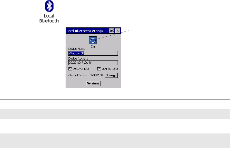
Chapter 3 — Configuring the CK60 Computer
CK60 Series Handheld Computer User’s Manual 55
Its key features are robustness, low complexity, low power, and low cost.
The technology offers wireless access to LANs, the mobile phone network,
and the internet for a host of home appliances and portable hand-held
devices located
up to 100m (328ft) apart (in a line of sight environment).
Local Bluetooth
The Local Bluetooth control panel applet displays the device name, the
device address, enables or disables Bluetooth communications, and sets dis-
coverable and connectable settings. This also provides a versions screen for
various Bluetooth items in the system.
Use this applet to enable Bluetooth communications before you configure
radio communications.
Wireless Printing
The Wireless Printing control panel applet separates the task of wireless
printing from other Bluetooth management items not relevant to this task.
Wireless Printing has a concept of the “current wireless printer.” This
printer is the one to which the CK60 Computer makes a connection when
the wireless printing COM port is opened. If there is no current wireless
printer, there is no wireless printing COM port. Registration and deregis-
tration of this COM port is controlled by BTCC. Use the Wireless Printing
control panel applet to handle the COM port registration. Customer soft-
1Select Start > Settings > Control Panel, then double-tap the Local Blue-
tooth icon.
2Tap the top button to On, then tap OK to close the applet.
Device Name Provides the “friendly” name of your CK60 Computer.
Device Address Universally unique and cannot be changed - read-only.
Discoverable Check this to ensure your CK60 is discoverable to other Bluetooth devices. The default is for the
CK60 Computer to be undiscoverable as it does not offer any incoming services out of the box.
Connectable Check this to allow other Bluetooth devices to connect to your CK60 Computer. The default is for
the CK60 Computer to be unconnectable as it does not offer any incoming services out of the box.
Class of Device This sets how a CK60 appears to other devices during a device discovery. The default is “0x920100”
which specifies that the CK60 is capable of services of information, object transfer, and networking.
Tap this to “On”
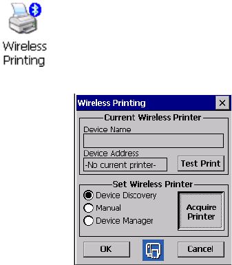
Chapter 3 — Configuring the CK60 Computer
56 CK60 Series Handheld Computer User’s Manual
ware or other test applications can also use this applet to manage the COM
port registration and deregistration.
The current wireless printer is stored in the registry and is registered and
deregistered on Bluetooth stack load/unload. If the current wireless printer
changes, the existing wireless printing COM port is deregistered, and the
new one is registered instead. The registered COM port is stored in the reg-
istry as the “WPort.”
For more information on using Bluetooth communications, see the Wireless
Printing Development Guide available on the Intermec Developer’s Library
CD or the Intermec web site at www.intermec.com.
Use any of the following methods to set the wireless printer:
• Use a Bluetooth device discovery to locate the remote device (page 56)
• Manually enter the remote Bluetooth Device Address (page 57)
• Use the Bluetooth Device Manager to choose from previously discovered
printers (page 58)
To do a Bluetooth device discovery:
You can set your wireless printer via a Bluetooth Device Discovery, which
takes about half a minute to locate all Bluetooth devices in your range.
3
Momentarily, Bluetooth devices discovered within range appear. If
your preferred printer is in the list, select to highlight the printer, then
tap
OK
. If you do not see your preferred device, make sure this device
is powered on and set to discovery, then tap
Device Discovery
again.
1Select Start > Settings > Control Panel, then double-tap the Wireless
Printing icon.
2Select Device Discovery, then tap Acquire Printer to initiate the device
discovery.

Chapter 3 — Configuring the CK60 Computer
CK60 Series Handheld Computer User’s Manual 57
Click
Cancel
to return to the first screen without making changes.
To enter the remote device address, if you know the Bluetooth Device
Address of the printer you want to use, you do the following to avoid
Device Discovery and perform a manual setup.
3Type the address of your device in the field, then click OK. Tap Cancel
to return to the first screen without making changes.
When you set your printer manually, your device does not receive the
printer name. Therefore, “-unknown-” is displayed under Device Name
unless you enter the correct value in to the registry in some other way.
1Select Start > Settings > Control Panel, then double-tap the Wireless
Printing icon.
2Select Manual, then tap Acquire Printer to go to the Manual Set dialog.

Chapter 3 — Configuring the CK60 Computer
58 CK60 Series Handheld Computer User’s Manual
To choose from previously discovered printers, do the following to select
from a list of previously discovered printers:
3Select to highlight the printer of choice, then tap OK. Tap Cancel to
return to the first screen without making changes.
Bluetooth DUN
Do the following to enable Bluetooth DUN on the CK60 Computer:
1Select Start > Settings > Control Panel, then double-tap the Wireless
Printing icon.
2Select Device Manager, then tap Acquire Printer to go to the list of pre-
viously discovered printers.
1Select Start > Settings > Control Panel, then double-tap the Network
and Dial-up Connections icon.
2Double-tap Make New Connection, type your connection name, check
Dial-Up Connection, then tap Next to continue.

Chapter 3 — Configuring the CK60 Computer
CK60 Series Handheld Computer User’s Manual 59
3Select “Bluetooth” from the Select a modem drop-down list, then tap
Bluetooth to access the Add Bluetooth Modem dialog.
4Tap Discover to discover and link to a Bluetooth modem or to a Blue-
tooth-enabled mobile phone.
5When prompted, enter the passkey in the Authentication Request dia-
log. The default passkey should be listed in the user manual for your periph-
eral device.
6Select your device from the list of discovered devices, then tap Bond.

Chapter 3 — Configuring the CK60 Computer
60 CK60 Series Handheld Computer User’s Manual
On successful bonding, notification appears at the bottom of the dialog,
such as in the following illustration.
7Tap Exit to complete the discovery and bonding of your device, tap
Next, enter the phone number for your connection, then tap Finish to
close the dialog.
8Double-tap your connection icon, enter your dial-up networking
account information in the User Name and Password fields, then tap
Connect to establish a connection.
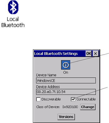
Chapter 3 — Configuring the CK60 Computer
CK60 Series Handheld Computer User’s Manual 61
Configuring the SF51 Scanner
The following information pertains to configuring the SF51 Scanner to
work with you CK60 Computer. These instructions assume you have the
EasySet application installed on your desktop or laptop. The EasySet appli-
cation is available from the Intermec Data Capture web site, contact your
Intermec representative for information about this application.
Enabling Bluetooth
Bluetooth is required for the SF51 Scanner. On the CK60 Computer, use
the Local Bluetooth control panel applet to enable Bluetooth communica-
tions before you configure the SF51 Scanner.
3Tap OK to close the applet.
1Select Start > Settings > Control Panel, then double-tap the Local Blue-
tooth icon.
2Tap the top button to On, check Connectable, then take note of the
device address. You will need this address to create your SF51 Connec-
tion Labels. Instructions start on the next page.
Tap this to “On“
Check to enable “Connectable”
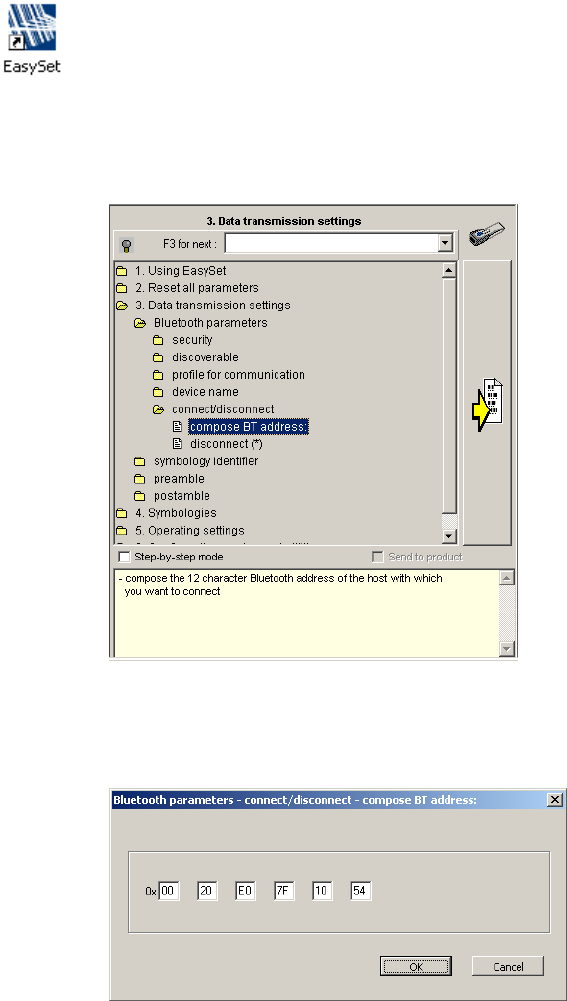
Chapter 3 — Configuring the CK60 Computer
62 CK60 Series Handheld Computer User’s Manual
Creating an SF51 Connection Label
To initiate a connection from the SF51 Scanner, use your EasySet applica-
tion to create an SF51 connection label with the CK60 Bluetooth address.
The device address is listed in the Local Bluetooth control panel applet on
your CK60 Computer, like the illustration shown on the previous page.
2In the left side of the EasySet application, double-click Data transmis-
sion settings > Bluetooth parameters > connect/disconnect > compose
BT address.
3Enter the Bluetooth address assigned to your CK60 Computer (shown
in your Local Bluetooth control panel applet), then click OK to close
this dialog.
1On your desktop or laptop, double-click the EasySet icon to activate the
EasySet application if you have not already done so.
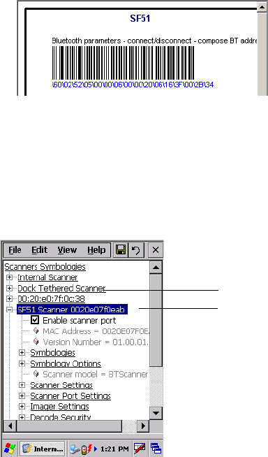
Chapter 3 — Configuring the CK60 Computer
CK60 Series Handheld Computer User’s Manual 63
4The connection label for the SF51 Scanner appears to the right in the
EasySet application, similar to the following.
Scan the label once, then
confirm the blue light on end of the SF51 Scanner starts blinking,
which means it is trying to connect.
When connected, the blue light
assumes a steady blue, then SF51 data gets wedged through the keyboard
interface.
Viewing SF51 Scanner Information from Your CK60 Computer
Note that in the CK60 Computer, the Intermec Settings control panel
applet can display up to seven separate SF51 connections. The following
illustration shows two such connections under the Scanners, Symbologies
option.
In this applet, tap Scanners, Symbologies, then tap (+) to expand the SF51
Scanner connections to view MAC addresses, firmware version numbers,
and whether each scanner is connected to the CK60 Computer. When you
clear (uncheck) Enable scanner port, the SF51 Scanner is disconnected
from the CK60 Computer. Check Enable scanner port again to reconnect.
If you want to rename these connections to descriptions more suitable for
your situation, press the stylus on each SF51 Scanner connection for a pop-
up menu, then select Rename. Enter the new description, then tap ok to
save your entry.
When the SF51 Scanner is connected, configuration changes take effect
immediately. When the SF51 Scanner is not connected, configuration
changes take effect once the SF51 Scanner is reconnected.
SF51 identified by device address
SF51 default name
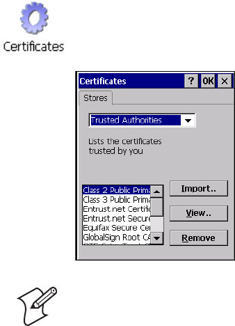
Chapter 3 — Configuring the CK60 Computer
64 CK60 Series Handheld Computer User’s Manual
Configuring Security
Use the next sections to understand how to configure each type of security
on your wireless CK60 Computer. If you choose not to use security, see
“Using Configuration Parameters” on page 90 for help.
If you are using 802.1x security, this sections also assumes that your
authentication server and access points are properly configured.
Loading Certificates
If you choose to use Transport Layer Security (TLS) with WPA or 802.1x
security, you need to have a unique client certificate on the CK60 Com-
puter and a trusted root certificate authority (CA) certificate. If you choose
to use PEAP, you need to load a root CA certificate. You can use a third-
party CA to issue unique client certificates and a root certificate.
Wireless Network
Your wireless adapter (network interface card) connects to wireless net-
works of two types: infrastructure networks and ad-hoc networks.
• Infrastructure networks get you onto your corporate network and the
internet. Your CK60 Computer establishes a wireless connection to an
access point, which links you to the rest of the network. When you con-
nect to a network via an access point, you are using the 802.11b/g infra-
structure mode.
• Ad-hoc networks are private networks shared between two or more cli-
ents, even with no access point.
Each wireless network is assigned a name (or Service Set Identifier - SSID)
to allow multiple networks to exist in the same area without infringement.
If your CA is on your WLAN, select Start > Settings > Control Panel, then
double-tap the Certificates icon to access the Certificate control panel
applet and obtain the certificates.
Note: Do not perform a cold-boot on the CK60 Computer. This resets the
time and date.
Chapter 3 — Configuring the CK60 Computer
CK60 Series Handheld Computer User’s Manual 65
Intermec Technologies recommends using security measures with wireless
networks to prevent unauthorized access to your network and to ensure
your privacy of transmitted data. The following are required elements for
secure networks:
• Authentication by both the network and the user
• Authentication is cryptographically protected
• Transmitted data
There are many schemes available for implementing these features.
Terminology
Below are terms you may encounter as you configure your wireless net-
work:
AES
(Advanced
Encryption
Standard)
A block cipher, a type of symmetric key cipher that uses groups of bits of a fixed length - called
blocks. A symmetric key cipher is a cipher that uses the same key for both encryption and
decryption.
CKIP (Cisco
Key Integrity
Protocol)
This is Cisco's version of the TKIP protocol, compatible with Cisco Airnet products.
EAP
(Extensible
Authentication
Protocol)
802.11b/g uses this protocol to perform authentication. This is not necessarily an authentication
mechanism, but is a common framework for transporting actual authentication protocols. Intermec
provides a number of EAP protocols for you to choose the best for your network.
TKIP
(Temporal Key
Integrity
Protocol)
This protocol is part of the IEEE 802.11i encryption standard for wireless LANs., which provides
per-packet key mixing, a message integrity check and a re-keying mechanism, thus overcoming most
of the weak points of WEP. This encryption is more difficult to crack than the standard WEP.
Weak points of WEP include:
• No Installation Vector (IV) reuse protection
• Weak keys
• No protection against message replay
• No detection of message tampering
• No key updates
WEP (Wired
Equivalent
Privacy)
encryption
With preconfigured WEP, both the client CK60 Computer and access point are assigned the same
key, which can encrypt all data between the two devices. WEP keys also authenticate the CK60
Computer to the access point - unless the CK60 Computer can prove it knows the WEP key, it is
not allowed onto the network.
WEP keys are only needed if they are expected by your clients. There are two types available: 64-bit
(5-character strings, 12345) (default) and 128-bit (13-character strings, 1234567890123). Enter
these as either ASCII (12345) or Hex (0x3132333435).
WPA (Wi-Fi
Protected
Access)
This is an enhanced version of WEP that does not rely on a static, shared key. It encompasses a
number of security enhancements over WEP, including improved data encryption via TKIP and
802.11b/g authentication with EAP.
WiFi Alliance security standard is designed to work with existing 802.11 products and to offer
forward compatibility with 802.11i.
WPA2 (Wi-Fi
Protected
Access)
Second generation of WPA security. Like WPA, WPA2 provides enterprise and home Wi-Fi users
with a high level of assurance that their data remains protected and that only authorized users can
access their wireless networks. WPA2 is based on the final IEEE 802.11i amendment to the 802.11
standard ratified in June 2004. WPA2 uses the Advanced Encryption Standard (AES) for data
encryption and is eligible for FIPS (Federal Information Processing Standards) 140-2 compliance.
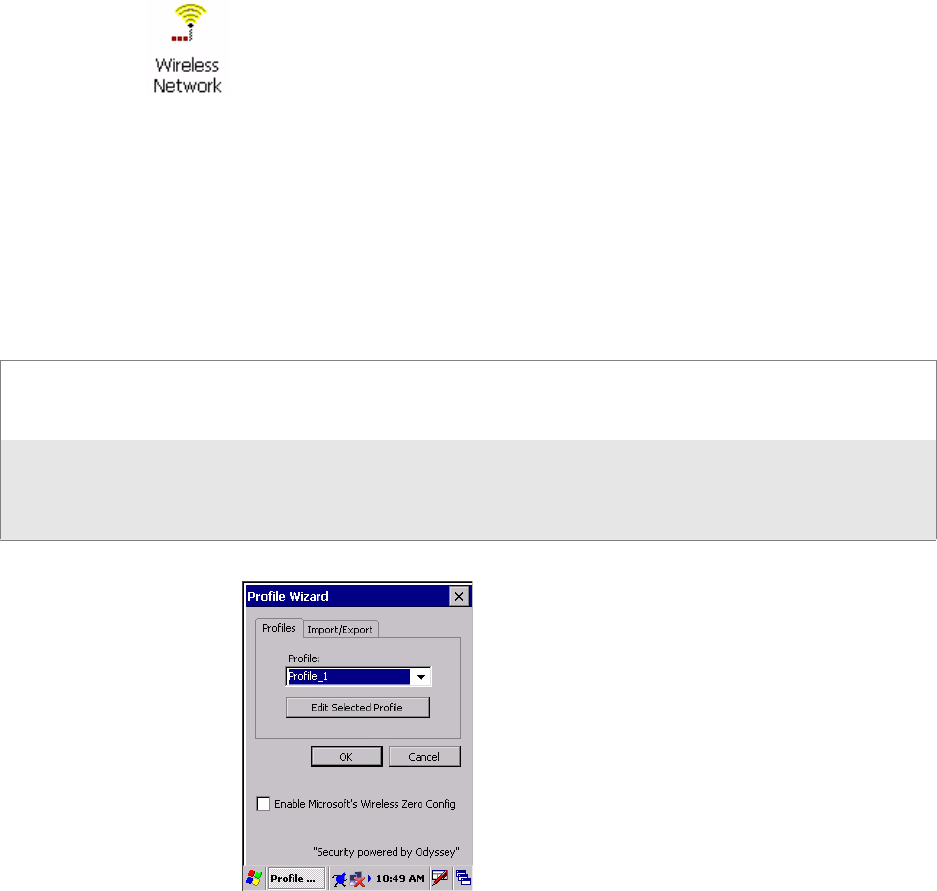
Chapter 3 — Configuring the CK60 Computer
66 CK60 Series Handheld Computer User’s Manual
Configuring Your Wireless Network
A profile contains all the information necessary to authenticate you to the
network, such as login name, password or certificate, and protocols by
which you are authenticated.
You can have up to four profiles for different networks. For example, you
may have different login names or passwords on different networks, or you
may use a password on one network, and a certificate on another.
Use the Profiles page to select and configure between the networking envi-
ronments assigned to this 802.11b/g radio.
To start 802.11b/g communications on the CK60 Computer, tap Start >
Settings > Control Panel, then double-tap the Wireless Network icon to
access the Profile Wizard for the 802.11b/g radio module.
Profile Tap the drop-down list to choose between four different profiles assigned to this unit, then tap Edit
Select Profile, make the changes needed for this profile (starting on the next page), then tap OK to
return to the Profiles page.
Enable
Microsoft's
Wireless Zero
Config
Check this box to enable Microsoft's Wireless Zero Config application. This effectively disables the
Intermec software solution for 802.11b/g, including configuration via the Wireless Network control
panel applet.
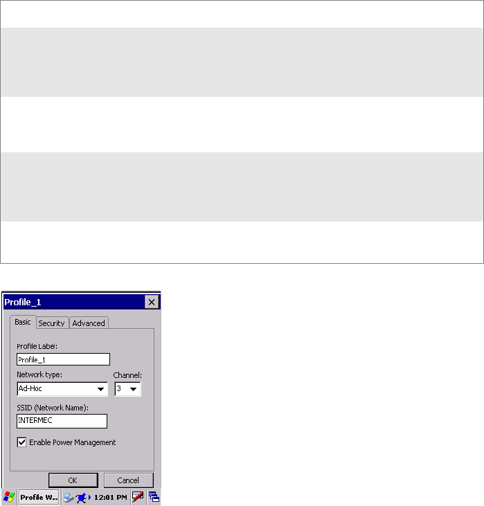
Chapter 3 — Configuring the CK60 Computer
CK60 Series Handheld Computer User’s Manual 67
Basic
Use the Basic page to set the network type, name, and manage battery
power for this profile. Tap ok or OK to return to the Profiles page.
Security
The following are available from the 8021x Security drop-down list. Note
that the last four methods are available if you have purchased the security pack-
age. Contact your Intermec representative for information.
•None (next page)
•PEAP (page 70)
•TLS (page 75)
•TTLS (page 79)
•LEAP (page 383)
Profile Label Enter a unique name for your profile.
Network type Tap the drop-down list to select either “Infrastructure” if your
network uses access points to provide connectivity to the corporate
network or internet; or “Ad-Hoc” to set up a private network with
one or more participants.
Channel If you select “Ad-Hoc” for the network type, select the channel on
which you are communicating with others in your network. There
are up to 11 channels available.
SSID
(Network
Name)
This assumes the profile name unless another name is entered in this
field. If you want to connect to the next available network or are not
familiar with the network name, enter ANY" in this field. Consult
your LAN administrator for network names.
Enable Power
Management:
Check this box to conserve battery power (default), or clear this box
to disable this feature.

Chapter 3 — Configuring the CK60 Computer
68 CK60 Series Handheld Computer User’s Manual
None
Use “None” to disable 802.11b/g Security and enable WEP encryption.
To Disable 802.1x Security
1Set 8021x Security as “None.”
2Set Association to “Open.”
3Set Encryption to “None.”
To Enable WEP Encryption
1Set 8021x Security as “None.”
2Set Association to either “Open” if WEP keys are not required; or
“Shared” when WEP keys are required for association.
3Set Encryption to “WEP.” See page 65 for information about WEP
encryption.
4If you had set Association to “Shared,” then select a data transmission
key from the Data TX Key drop-down list near the bottom of this
screen, then enter the encryption key for that data transmission in the
appropriate Key # field.
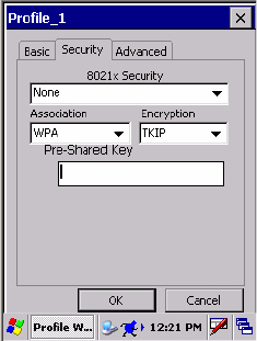
Chapter 3 — Configuring the CK60 Computer
CK60 Series Handheld Computer User’s Manual 69
To Enable WPA Encryption Using a Preshared Key
1Set 8021x Security as “None.”
2Set Association to “WPA.” See page 65 for information about WPA
encryption.
3Skip Encryption as it is automatically set to “TKIP.” See page 65 for
more information about TKIP.
4Enter the temporal key as ASCII (12345) in the Pre-Shared Key field.
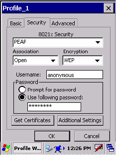
Chapter 3 — Configuring the CK60 Computer
70 CK60 Series Handheld Computer User’s Manual
PEAP (Protected EAP)
This protocol is suitable for performing secure authentication against Win-
dows domains and directory services. It is comparable to EAP-TTLS (see
page 65), both in its method of operation and its security, though not as
flexible. This does not support the range of inside-the-tunnel authentica-
tion methods supported by EAP-TTLS. Microsoft and Cisco both support
this protocol.
Use “PEAP” to configure the use of PEAP as an authentication protocol
and to select “Open,” “WPA,” “WPA2,” or “Network EAP” as an associa-
tion mode.
To Enable PEAP with an Open Association
1Set 8021x Security as “PEAP.”
2Set Association to “Open.”
3Skip Encryption as it is automatically set to “WEP.” See page 65 for
more information about WEP.
4Enter your unique user name and password to use this protocol. Select
Prompt for password to have the user enter this password each time to
access the protocol; or leave Use following password as selected to auto-
matically use the protocol without entering a password.
5Tap Get Certificates to obtain or import server certificates. See page 84
for more information.
6Tap Additional Settings to assign an inner PEAP authentication and set
options for server certificate validation and trust. See page 74 for more
information.
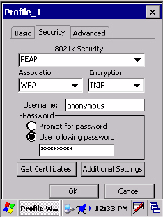
Chapter 3 — Configuring the CK60 Computer
CK60 Series Handheld Computer User’s Manual 71
To Enable PEAP with WPA Encryption
1Set 8021x Security as “PEAP.”
2Set Association to “WPA.” See page 65 for information about WPA
encryption.
3Skip Encryption as it is automatically set to “TKIP.” See page 65 for
more information about TKIP.
4Enter your unique user name and password to use this protocol. Select
Prompt for password to have the user enter this password each time to
access the protocol; or leave Use following password as selected to auto-
matically use the protocol without entering a password.
5Tap Get Certificates to obtain or import server certificates. See page 84
for more information.
6Tap Additional Settings to assign an inner PEAP authentication and set
options for server certificate validation and trust. See page 74 for more
information.
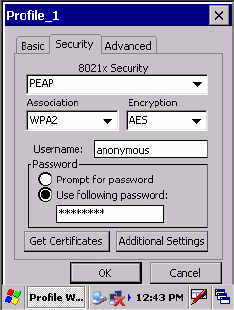
Chapter 3 — Configuring the CK60 Computer
72 CK60 Series Handheld Computer User’s Manual
To Enable PEAP with WPA2 Encryption
1Set 8021x Security as “PEAP.”
2Set Association to “WPA2.” See page 65 for information about WPA2
encryption.
3Select Encryption to either “TKIP” or “AES.” See page 65 for more
information about TKIP and page 65 for more information about AES.
4Enter your unique user name and password to use this protocol. Select
Prompt for password to have the user enter this password each time to
access the protocol; or leave Use following password as selected to auto-
matically use the protocol without entering a password.
5Tap Get Certificates to obtain or import server certificates. See page 84
for more information.
6Tap Additional Settings to assign an inner PEAP authentication and set
options for server certificate validation and trust. See page 74 for more
information.
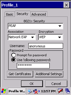
Chapter 3 — Configuring the CK60 Computer
CK60 Series Handheld Computer User’s Manual 73
To Enable PEAP with Network EAP
1Set 8021x Security as “PEAP.”
2Set Association to “Network EAP.” See page 65 for information about
EAP.
3Select Encryption to either “WEP” or “CKIP.” See page 65 for more
information about WEP and page 65 for more information about CKIP.
4Enter your unique user name and password to use this protocol. Select
Prompt for password to have the user enter this password each time to
access the protocol; or leave Use following password as selected to auto-
matically use the protocol without entering a password.
5Tap Get Certificates to obtain or import server certificates. See page 84
for more information.
6Tap Additional Settings to assign an inner PEAP authentication and set
options for server certificate validation and trust. See page 74 for more
information.
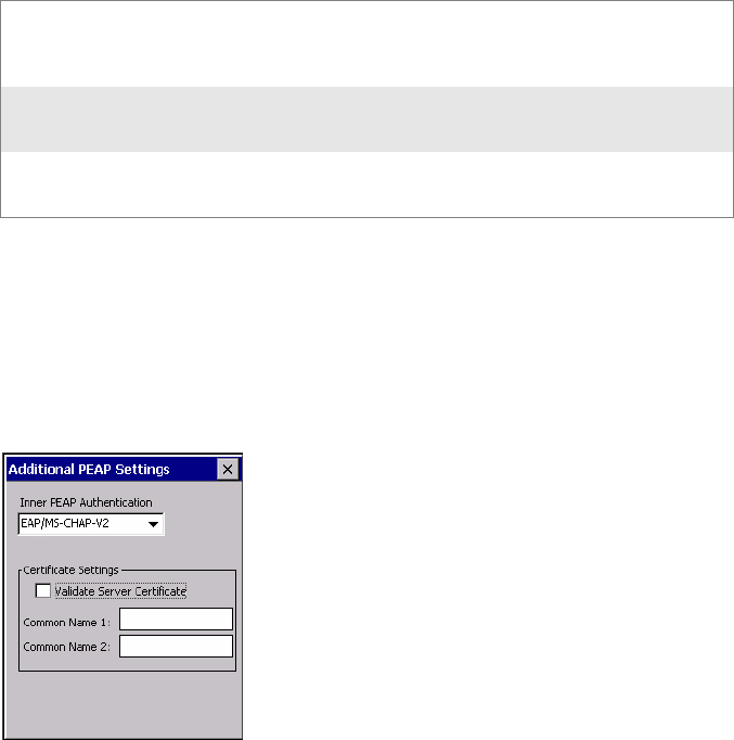
Chapter 3 — Configuring the CK60 Computer
74 CK60 Series Handheld Computer User’s Manual
Additional PEAP Settings
1Select an authentication method from the Inner PEAP Authentication
drop-down list.
2Check Validate Server Certificate to verify the identity of the authenti-
cation server based on its certificate when using PEAP.
3Enter the Common Names of trusted servers. Note that if these fields are
left blank, the server certificate trust validation is not performed or required.
4Click X to return to the Security page.
EAP/MS-CHAP-V2 Authenticates against a Windows Domain Controller
and other non-Windows user databases. This is
Microsoft's implementation of PEAP.
EAP/Token Card Use with token cards. The password value entered is
never cached. This is Cisco's implementation of PEAP.
EAP/MD5-Challenge Message Digest 5. A secure hashing authentication
algorithm.
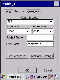
Chapter 3 — Configuring the CK60 Computer
CK60 Series Handheld Computer User’s Manual 75
TLS (EAP-TLS)
EAP-TLS is a protocol that is based on the TLS (Transport Layer Security)
protocol widely used to secure web sites. This requires both the user and
authentication server have certificates for mutual authentication. While
cryptically strong, this requires corporations that deploy this to maintain a
certificate infrastructure for all their users.
Use “TLS” to configure the use of EAP-TLS as an authentication protocol,
and select “Open,” “WPA,” “WPA2,” or “Network EAP” as an association
mode.
To Enable TLS with an Open Association
1Set 8021x Security as “TLS.”
2Set Association to “Open.”
3Skip Encryption as it is automatically set to “WEP.” See page 65 for
information about WEP encryption.
4Enter your unique Subject Name and User Name to use this protocol.
5Tap Get Certificates to obtain or import server certificates. See page 84
for more information.
6Tap Additional Settings to set options for server certificate validation
and trust. See page 78 for more information.
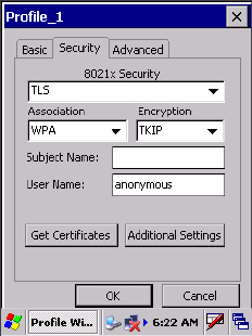
Chapter 3 — Configuring the CK60 Computer
76 CK60 Series Handheld Computer User’s Manual
To Enable TLS with WPA Encryption
1Set 8021x Security as “TLS.”
2Set Association to “WPA.” See page 65 for information about WPA
encryption.
3Skip Encryption as it is automatically set to “TKIP.” See page 65 for
more information about TKIP.
4Enter your unique Subject Name and User Name as credentials for this
profile.
5Tap Get Certificates to obtain or import server certificates. See page 84
for more information.
6Tap Additional Settings to set options for server certificate validation
and trust. See page 78 for more information.
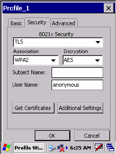
Chapter 3 — Configuring the CK60 Computer
CK60 Series Handheld Computer User’s Manual 77
To Enable TLS with WPA2 Encryption
1Set 8021x Security as “TLS.”
2Set Association to “WPA2.” See page 65 for information about WPA2
encryption.
3Select Encryption to either “TKIP” or “AES.” See page 65 for more
information about TKIP and page 65 for more information about AES.
4Enter your unique Subject Name and User Name as credentials for this
profile.
5Tap Get Certificates to obtain or import server certificates. See page 84
for more information.
6Tap Additional Settings to set options for server certificate validation
and trust. See page 78 for more information.

Chapter 3 — Configuring the CK60 Computer
78 CK60 Series Handheld Computer User’s Manual
To Enable TLS with Network EAP
1Set 8021x Security as “TLS.”
2Set Association to “Network EAP.” See page 65 for information about
EAP.
3Select Encryption to either “WEP” or “CKIP.” See page 65 for more
information about WEP and page 65 for more information about CKIP.
4Enter your unique Subject Name and User Name as credentials for this
profile.
5Tap Get Certificates to obtain or import server certificates. See page 84
for more information.
6Tap Additional Settings to set options for server certificate validation
and trust. See page 78 for more information.
Additional TLS Settings
1Check Validate Server Certificate to verify the identity of the authenti-
cation server based on its certificate when using TLS.
2Enter the Common Names of trusted servers. Note that if these fields are
left blank, the server certificate trust validation is not performed or required.
3Click X to return to the Security page.
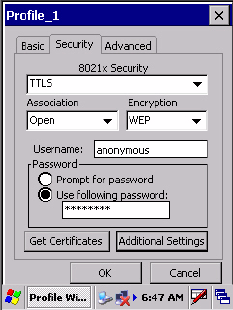
Chapter 3 — Configuring the CK60 Computer
CK60 Series Handheld Computer User’s Manual 79
TTLS (EAP-Tunneled TLS)
This protocol provides authentication like EAP-TLS (see page 75) but does
not require certificates for every user. Instead, authentication servers are
issued certificates. User authentication is done using a password or other
credentials that are transported in a securely encrypted “tunnel” established
using server certificates.
EAP-TTLS works by creating a secure, encrypted tunnel through which
you present your credentials to the authentication server. Thus, inside EAP-
TTLS there is another inner authentication protocol that you must configure
via Additional TTLS Settings.
Use “TTLS” to configure the use of EAP-TTLS as an authentication proto-
col, and select “Open,” “WPA,” “WPA2,” or “Network EAP” as an associa-
tion mode.
To Enable TTLS with an Open Association (default configuration)
1Set 8021x Security as “TTLS.”
2Set Association to “Open.”
3Skip Encryption as it is automatically set to “WEP.” See page 65 for
information about WEP encryption.
4Enter your unique user name and password to use this protocol. Select
Prompt for password to have the user enter this password each time to
access the protocol, or leave Use following password as selected to auto-
matically use the protocol without entering a password.
5Tap Get Certificates to obtain or import server certificates. See page 84
for more information.
6Tap Additional Settings to assign an inner TTLS authentication and an
inner EAP, and set options for server certificate validation and trust. See
page 83 for more information.
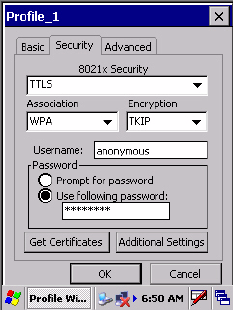
Chapter 3 — Configuring the CK60 Computer
80 CK60 Series Handheld Computer User’s Manual
To Enable TTLS with WPA Encryption
1Set 8021x Security as “TTLS.”
2Set Association to “WPA.” See page 65 for information about WPA
encryption.
3Skip Encryption as it is automatically set to “TKIP.” See page 65 for
more information about TKIP.
4Enter your unique user name and password to use this protocol. Select
Prompt for password to have the user enter this password each time to
access the protocol, or leave Use following password as selected to auto-
matically use the protocol without entering a password.
5Tap Get Certificates to obtain or import server certificates. See page 84
for more information.
6Tap Additional Settings to assign an inner TTLS authentication and an
inner EAP, and set options for server certificate validation and trust. See
page 83 for more information.
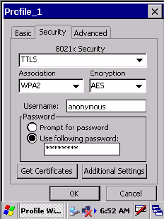
Chapter 3 — Configuring the CK60 Computer
CK60 Series Handheld Computer User’s Manual 81
To Enable TTLS with WPA2 Encryption
1Set 8021x Security as “TTLS.”
2Set Association to “WPA2.” See page 65 for information about WPA2
encryption.
3Select Encryption to either “TKIP” or “AES.” See page 65 for more
information about TKIP and page 65 for more information about AES.
4Enter your unique user name and password to use this protocol. Select
Prompt for password to have the user enter this password each time to
access the protocol, or leave Use following password as selected to auto-
matically use the protocol without entering a password.
5Tap Get Certificates to obtain or import server certificates. See page 84
for more information.
6Tap Additional Settings to assign an inner TTLS authentication and an
inner EAP, and set options for server certificate validation and trust. See
page 83 for more information.
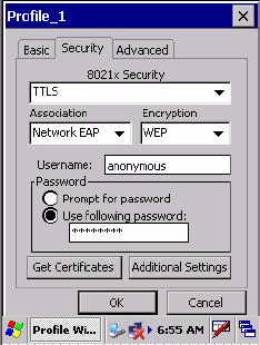
Chapter 3 — Configuring the CK60 Computer
82 CK60 Series Handheld Computer User’s Manual
To Enable TTLS with Network EAP
1Set 8021x Security as “TTLS.”
2Set Association to “Network EAP.” See page 65 for information about
EAP.
3Select Encryption to either “WEP” or “CKIP.” See page 65 for more
information about WEP and page 65 for more information about CKIP.
4Enter your unique user name and password to use this protocol. Select
Prompt for password to have the user enter this password each time to
access the protocol, or leave Use following password as selected to auto-
matically use the protocol without entering a password.
5Tap Get Certificates to obtain or import server certificates. See page 84
for more information.
6Tap Additional Settings to assign an inner TTLS authentication and an
inner EAP, and set options for server certificate validation and trust. See
page 83 for more information.
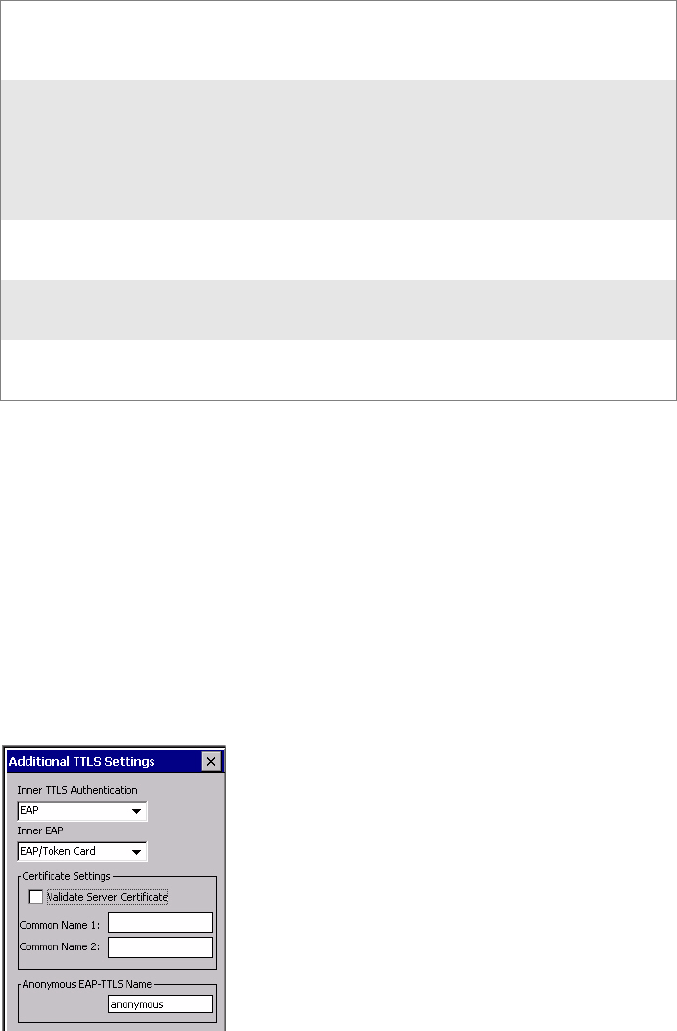
Chapter 3 — Configuring the CK60 Computer
CK60 Series Handheld Computer User’s Manual 83
Additional TTLS Settings
1Select an authentication method from the Inner TTLS Authentication
drop-down list.
2If you select “EAP” for the inner authentication protocol, then select an
inner EAP protocol from the Inner EAP drop-down list.
3Enter the Common Names of trusted servers. Note that if these fields are
left blank, the server certificate trust validation is not performed or required.
4Check Validate Server Certificate to verify the identity of the authenti-
cation server based on its certificate when using TTLS.
5Enter the Anonymous EAP-TTLS Name as assigned for public usage.
Use of this outer identity protects your login name or identity.
6Click X to return to the Security page.
PAP Password Authentication Protocol. A simple
authentication protocol that sends security
information in the clear.
CHAP Challenge Handshake Authentication Protocol. Use
of Radius to authenticate a terminal without sending
security data in the clear. Authenticates against non-
Windows user databases. You cannot use this if
authenticating against a Windows NT Domain or
Active Directory.
MS-CHAP; MS-CHAP-V2 Authenticates against a Windows Domain
Controller and other non-Windows user databases.
PAP/Token Card Use with token cards. The password value entered is
never cached.
EAP Extensible Authentication Protocol. See page 65 for
information about EAP.
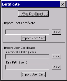
Chapter 3 — Configuring the CK60 Computer
84 CK60 Series Handheld Computer User’s Manual
To Get Certificates
Certificates are pieces of cryptographic data that guarantee a public key is
associated with a private key. They contain a public key and the entity
name that owns the key. Each certificate is issued by a certificate authority.
Use this page to import a certificate onto the CK60 Computer.
Root Certificates
1Tap the <<< button next to the Import Root Certificate field to select
the root certificate (DER-encoded .CER file) to import.
2Click Import Root Cert to install the selected certificate.
User Certificate
1Tap the <<< button next to the Certificate Path field to select the user
certificate (DER-encoded .CER file without the private key) to import.
2Tap the <<< button next to the Key Path field to select the private key
(.PVK file) which corresponds to the user certificate chosen in step 1.
3Tap Import User Cert to install the selected certificate.
Web Enrollment
Tap Web Enrollment to obtain a user certificate over the network from an
IAS Server. Tap X to return to the Security page.
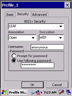
Chapter 3 — Configuring the CK60 Computer
CK60 Series Handheld Computer User’s Manual 85
LEAP (Cisco Lightweight EAP)
LEAP is the Cisco Lightweight version of EAP. See page 65 for information
about EAP.
Use “LEAP” to configure the use of LEAP as an authentication protocol,
select “Open,” “WPA,” “WPA2,” or “Network EAP” as an association
mode, or assign “Network EAP.” Note that this defaults to the Network EAP.
To Enable LEAP with an Open Association
1Set 8021x Security as “LEAP.”
2Set Association to “Open.”
3Skip Encryption as it is automatically set to “WEP.” See page 65 for
more information about WEP.
4Enter your unique User Name to use this protocol.
5Select Prompt for password to have the user enter this password each
time to access the protocol, or leave Use following password as selected
to automatically use the protocol without entering a password.
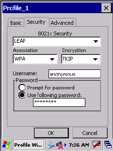
Chapter 3 — Configuring the CK60 Computer
86 CK60 Series Handheld Computer User’s Manual
To Enable LEAP with WPA Encryption
1Set 8021x Security as “LEAP.”
2Set Association to “WPA.” See page 65 for information about WPA
encryption.
3Skip Encryption as it is automatically set to “TKIP.” See page 65 for
more information about TKIP.
4Enter your unique User Name to use this protocol.
5Select Prompt for password to have the user enter this password each
time to access the protocol, or leave Use following password as selected
to automatically use the protocol without entering a password.
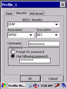
Chapter 3 — Configuring the CK60 Computer
CK60 Series Handheld Computer User’s Manual 87
To Enable LEAP with WPA2 Encryption
1Set 8021x Security as “LEAP.”
2Set Association to “WPA2.” See page 65 for information about WPA2
encryption.
3Select Encryption to either “TKIP” or “AES.” See page 65 for more
information about TKIP and page 65 for more information about AES.
4Enter your unique User Name to use this protocol.
5Select Prompt for password to have the user enter this password each
time to access the protocol, or leave Use following password as selected
to automatically use the protocol without entering a password.
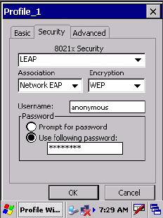
Chapter 3 — Configuring the CK60 Computer
88 CK60 Series Handheld Computer User’s Manual
To Enable LEAP with Network EAP
1Set 8021x Security as “PEAP.”
2Set Association to “Network EAP.” See page 65 for information about
EAP.
3Select Encryption to either “WEP” or “CKIP.” See page 65 for more
information about WEP and page 65 for more information about CKIP.
4Enter your unique User Name to use this protocol.
5Select Prompt for password to have the user enter this password each
time to access the protocol, or leave Use following password as selected
to automatically use the protocol without entering a password.
Advanced
Use this page to configure additional settings for this profile. Tap X to
return to the Profiles page.
•Detect Rogue APs:
Wireless NICs and APs associate based on the SSID configured for the
NIC. Given an SSID, the BSSID with the strongest signal is often cho-
sen for association. After association, 802.1x authentication may occur
and during authentication credentials to uniquely identify a user - these
are passed between the NIC and the AP.
The base 802.1x technology does not protect the network from “rogue
APs.” These can mimic a legitimate AP to authentication protocols and
user credentials. This provides illegal users ways to mimic legitimate
users and steal network resources and compromise security.
Check this box to detect and report client behavior suspected of being
rogue APs. Once a rouge AP is detected, your CK60 Computer no
longer associates with that AP until you perform a warm boot.
Clear this box to solve AP connection problems that result when an AP
gets put on the rogue AP list due to inadvertant failed authentications
and not because it is a real rouge.
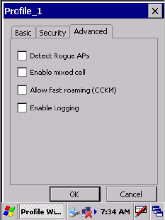
Chapter 3 — Configuring the CK60 Computer
CK60 Series Handheld Computer User’s Manual 89
•Enable mixed cell:
Mixed cell is a profile-dependent setting. If enabled, you can connect to
mixed cell without using WEP, then you can query the cell to determine
whether you can use encryption.
•Allow fast roaming (CCKM):
When using a wireless LAN that uses Cisco Access Points, a LEAP-
enabled client device can roam from one access point to another without
involving the authentication (RADIUS) server. If enabled, Cisco Cen-
tralized Key Management (CCKM), an access point configured to pro-
vide Wireless Domain Services (WDS) takes the place of the RADIUS
server (caching credentials of an initial authentication with the RADIUS
server) and authenticates the client without perceptible delay in voice or
other time-sensitive applications.
•Enable Logging:
Check this box to log what activity incurs for this profile.

Chapter 3 — Configuring the CK60 Computer
90 CK60 Series Handheld Computer User’s Manual
Using Configuration Parameters
A configuration parameter changes the way the CK60 Computer operates,
such as configuring a parameter to have the CK60 Computer emit a very
loud beep in a noisy environment. Use any of these methods to execute
configuration parameters:
Scan EasySet bar code labels:
You can use the EasySet application from Intermec Technolo-
gies Corporation to print configuration labels. Scan the labels
to change the imager configuration and data transfer settings.
For more information, see the EasySet online help.
Send Reader Commands through the Network or from an Application
You can configure parameters by sending the following reader
commands through the network or from an application. See
“Using Reader Commands” on page 91 for more information.
Reader
Command Description Options (Syntax Data
for Reader Commands)
Audio
Volume
Changes the volume of all audio signals 0 - Off
1 - Low
2 - Medium (default)
3 - High
4 - Very high
Automatic
Shutoff
Sets the length of time the CK60 Computer remains on when there is no
activity. When you turn on the CK60 Computer, it either resumes
exactly where it was when you turned in off or boots and restarts your
application.
1 - 1 minute
2 - 2 minutes
3 - 3 minutes (default)
4 - 4 minutes
5 - 5 minutes
Backlight
Timeout
Sets the length of time that the display backlight remains on. If you set a
longer timeout value, you use the battery power at a faster rate.
0 - Disable
10 - 10 seconds
30 - 30 seconds
60 - 1 minute (default)
120 - 2 minutes
180 - 3 minutes
240 - 4 minutes
300 - 5 minutes
Date/Time Sets the current date and time. Date
Year - 0000-9999 (1999)
Month - 1-12 (6)
Day - 1-31 (1)
Time
Hour - 0-23 (0)
Minute - 0-59 (00)
Second - 0-59 (00)

Chapter 3 — Configuring the CK60 Computer
CK60 Series Handheld Computer User’s Manual 91
Using Reader Commands
After the CK60 Computer is connected to your network, you can send the
CK60 Computer a reader command from an application to perform a task,
such as changing the time and date. Some reader commands temporarily
override the configuration settings and others change these settings.
Change Configuration
The Change Configuration command must precede any configuration
command. If you enter a valid string, the CK60 Computer configuration is
modified and the computer emits a high beep. To send the Change Config-
uration command through the network, use the
$+ [command]
syntax
where command is the two-letter command syntax for the configuration
command followed by the value to set for that command.
You can also make changes to several different commands by using the
$+ [command]...[command n]
syntax. There are seven configuration com-
mand settings that can be changed in this way. See each command for infor-
mation on respective acceptable “data” values.
Example 1
To change the Beep Volume to Off, you can send this string to the CK60
Computer through the network:
$+BV0
where:
$+
Indicates Change Configuration.
BV
Specifies the Audio Volume parameter.
0
Specifies a value of Off.
Example 2
To change the Beep Volume to Very Quiet and the Virtual Wedge Grid to
123:
$+BV1AF123
where:
$+
Indicates Change Configuration.
BV1
Specifies Audio Volume, set to Very Quiet (1)
AF123
Specifies Virtual Wedge Grid, set to a value of 123.
Command Syntax
Audio Volume BVdata
Automatic Shutoff EZdata
Backlight Timeout BFdata
Virtual Wedge Grid AFdata
Postamble AEdata
Preamble ADdata
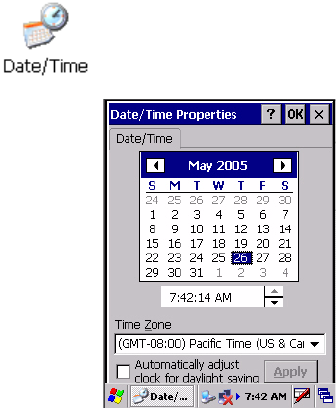
Chapter 3 — Configuring the CK60 Computer
92 CK60 Series Handheld Computer User’s Manual
Set Time and Date
This command sets the date and time on the CK60 Computer. The
default date and time is
June 1, 1999 at 12:00 AM
.
From the network, send the following:
/+ yyyymmddhhmmss
where acceptable values for the date are:
yyyy
0000-9999 Year
mm
01-12 Month of the year
dd
01-31 Day of the month
hh
00-23 Hour
mm
00-59 Minutes
ss
00-59 Seconds
You can also set the time and date by using the Date/Time control panel
applet. Tap Start > Settings > Control Panel, then double-tap the
Date/Time icon to configure the time and date.

CK60 Series Handheld Computer User’s Manual 93
4Maintaining the CK60
Computer
Use this chapter to upgrade the operating system, run diagnostics, solve
problems you may encounter, and perform routine maintenance on your
CK60 Handheld Computer:
Note: Desktop icons and control panel applet icons are shown to the left.
Any place that Start is mentioned, tap the following Windows icon in the
bottom, left corner of your CK60 desktop.
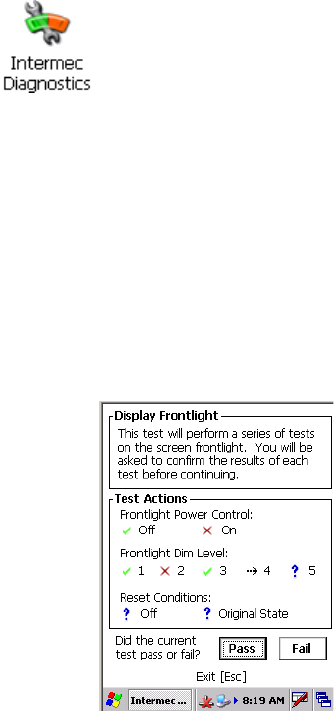
Chapter 4 — Maintaining the CK60 Computer
94 CK60 Series Handheld Computer User’s Manual
Upgrading the Operating System on your CK60 Computer
You can use the Intermec Recovery Tools CD to reinstall or upgrade the oper-
ating system software on the CK60 Computer. For more information, con-
tact your Intermec representative for more information about this CD.
When you upgrade the operating system, you erase the current configura-
tion and replace it with the new default configuration. You will need to
reset the network parameters on the CK60 Computer to reestablish com-
munications with other devices in the network. In other words, if you
upgrade the operating system and the default registry from the operating
system has changed, the registry is rolled back to the new default.
Running Diagnostics on Your CK60 Computer
Frontlight Test
Use this test to ensure that your frontlight functions properly. It turns the
frontlight on and off and sets brightness levels.
This test performs a series of tests on the screen frontlight. Tap either Pass
or Fail to confirm the results of each test before continuing. A green check
mark indicates a pass; a red “X” indicates a fail. The dashed arrow indicates
the action being tested.
Battery Information
Use this test to view information about the battery voltage, charge levels,
and AC line detection. The test would take less than a minute.
Use the Intermec Diagnostics control panel applet on the CK60 Computer
to analyze firmware problems and view system information. Tap Start >
Settings > Control Panel, then double-tap the Intermec Diagnostics icon
to access these tests and information. Select the appropriate test, then tap
Start Test to begin. Press Esc to exit any of the tests.

Chapter 4 — Maintaining the CK60 Computer
CK60 Series Handheld Computer User’s Manual 95
The Main Battery section displays the percentage of battery power remain-
ing in the battery. You can continue using the battery until the CK60
Computer indicates that the battery is low; the battery light turns on and
the low battery icon appears in the status bar.
The Backup Battery section indicates the percentage of battery power
remaining in the backup battery (super capacity). The main battery charges
the backup battery.
You can also use this screen to see the current volts and charging status.
Display Test
Use this test to check for display accuracy and ensure the physical display is
mounted properly and is visible. This test runs until you either press a key
or tap the display.
This test performs a series of tests on the display. An explanation of what to
expect is given before you press ACTION (Enter) to begin the test. When
done testing an action, press Esc to end the test, then tap either Pass or Fail
to confirm the results of the test before continuing to the next test.
A green check mark indicates a pass; a red “X” indicates a fail; the dashed
arrow indicates the action being tested.
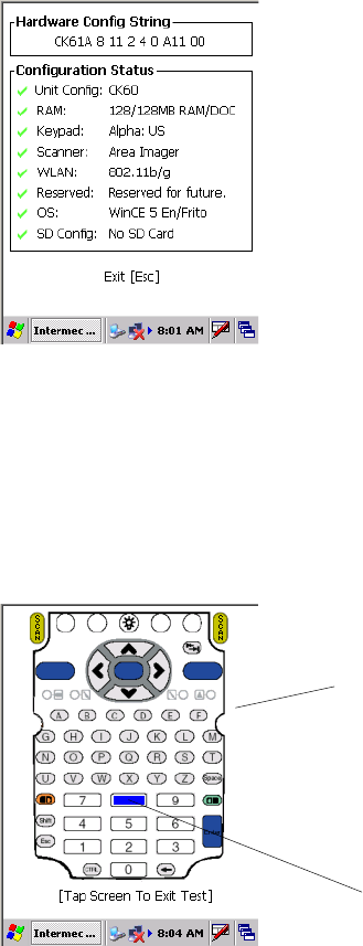
Chapter 4 — Maintaining the CK60 Computer
96 CK60 Series Handheld Computer User’s Manual
Hardware Configuration
Use this test to read the hardware configuration and display it onscreen.
The hardware configuration table shows important information about your
CK60 Computer, such as the serial number, configuration number, model,
software options, and scanner type. Share this information with your Inter-
mec representative when consulting about hardware and software that may
be installed at the factory.
A green check mark indicates a pass; a blue question mark indicates infor-
mation is not available; and a red “X” indicates inaccurate information.
Keyboard (Keypad) Test
Use this test to test the functionality of all the keys on your installed key-
pad. This test runs continuously until you tap the screen to exit. Note that
you do not test
I
key, or you will suspend the CK60 Computer. Press a key on
the keypad for the screen to cover the same key with a block of color -- note
the [8] key was pressed in the following illustration.
Tap screen to exit the keypad test
The [8] key was pressed.
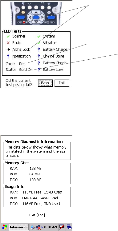
Chapter 4 — Maintaining the CK60 Computer
CK60 Series Handheld Computer User’s Manual 97
LED Test
Use this test to light each LED on the CK60 Computer to ensure each is
working properly. This test continuously turns the LEDs on the CK60
Computer on until you press Esc to exit. There are multiple LED tests, tap
OK on each test to go through the sequence, then tap either Pass or Fail to
confirm the results of the test before continuing to the next test.
The top portion of the display shows the area of the CK60 Computer being
tested. The Color and State descriptions in the left column indicate what
you should expect with each LED feature being tested.
A green check mark indicates a pass; a blue question mark indicates infor-
mation is not available or the feature was not tested; a red “X” indicates
inaccurate information; a dashed arrow indicates the feature being tested.
Memory Information
This displays the RAM, ROM, and Disk on Chip (DOC) memory
installed in the CK60 Computer and the size of each. Press Esc to exit.
LED being tested
Color LED should display
Action LED should perform

Chapter 4 — Maintaining the CK60 Computer
98 CK60 Series Handheld Computer User’s Manual
Networking Test
This test validates each required level of network connectivity. Tap Start
Tes t to begin the validation. Press Esc to exit.
A green check mark indicates a validation; a blue question mark indicates
the feature was not tested; a red “X” indicates the validation failed; a dashed
arrow indicates the feature being tested.
Read CPU Registers
Use this to read the CPU registers available in your CK60 Computer, then
create a log file listing the registers. Tap Start Test to read the CPU regis-
ters, then select any of the registers from the Register ID drop-down list to
view its register address and register value. Press Esc to exit.

Chapter 4 — Maintaining the CK60 Computer
CK60 Series Handheld Computer User’s Manual 99
Sound Test
Use this to cycle through a frequency table, record audio through the
microphone, and play back the recorded audio. Tap Start Test to begin the
series, then tap either Pass or Fail to confirm the results of the test before
continuing to the next test.
A green check mark indicates a pass; a blue question mark indicates the fea-
ture was not tested; a red “X” indicates the validation failed; a dashed arrow
indicates the feature being tested.
Touch Screen Test
Use this test to ensure your touchscreen works properly. Draw anywhere on
the screen with your stylus, press Esc to exit.
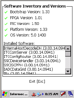
Chapter 4 — Maintaining the CK60 Computer
100 CK60 Series Handheld Computer User’s Manual
Software Inventory
Use this test to get the latest version information of your critical software
components. Press Esc to exit.
Troubleshooting Your CK60 Computer
If you have any problems using the CK60 Computer, look at the following
for possible solutions:
• Problems While Operating the CK60 Computer (page 101)
• Problems While Configuring the CK60 Computer (page 102)
• Problems While Configuring 802.1x Security (page 102)
• Problems with Wireless Connectivity (page 104)
• Problems Transmitting Data through the Serial Port (page 105)
• Problems While Scanning Bar Codes (page 105)

Chapter 4 — Maintaining the CK60 Computer
CK60 Series Handheld Computer User’s Manual 101
If you send the CK60 Computer in for service, it is your responsibility to
save the computer data and configuration. Intermec is responsible only for
ensuring that the keypad and other hardware features match the original
configuration when repairing or replacing your device.
Problems While Operating the CK60 Computer
Problem Solution
You press I to turn on the CK60 Computer and nothing
happens.
• Make sure the backlight is on by pressing E.
• Make sure you have a charged battery installed cor-
rectly. For help, see “Using the Battery” on page 6.
• The battery may be discharged. Replace the battery
with a spare charged battery, or charge the battery and
try again.
•Perform a warm-boot.
The Battery status LED is on. • If the battery status LED is a steady green, the battery
is more than 95% charged and unit is on a charger.
• If the battery status LED is blinking red, then the bat-
tery is low. The speed of the blinking increases as the
battery power gets increasingly lower.
• If the battery status LED is a steady red, the main bat-
tery is low, or if charging, then the LED remains red
until the CK60 Computer reaches 95% charge status.
• If the battery status LED is a steady yellow, then the
CK60 Computer is on a charging source and there is
no battery pack installed. This can also mean that the
CK60 Computer is out of charging range 32
°
to
122
°
F (0
°
to 50
°
C). Once the CK60 Computer gets
back in range, charging resumes and the LED changes
to red or green.
• If the battery status LED is a steady amber, then
replace the battery pack.
The CK60 Computer appears to be locked up and you
cannot enter data.
• Press I to turn off the CK60 Computer, then press I
again to turn on the CK60 Computer.
• Press and hold I for ten seconds to warm-boot the
CK60 Computer.
• Perform a cold-boot on the CK60 Computer. For
help, see “Resetting Your CK60 Computer” on
page 3.
• Try reloading the firmware. For help, see “Upgrading
the Operating System on your CK60 Computer” on
page 94.
• If the CK60 Computer will not boot or reset, contact
your local Intermec representative for help.

Chapter 4 — Maintaining the CK60 Computer
102 CK60 Series Handheld Computer User’s Manual
Problems While Configuring 802.1x Security
If you have trouble configuring the computer for 802.1x security, check
these problems and possible solutions.
Problems While Configuring the CK60 Computer
Problem Solution
You scan a configuration command, such as Beeper Vol-
ume, and you hear three low beeps.
If you are working in the Intermec Settings control panel
applet, you cannot scan configuration commands. Exit
the applet to scan configuration commands.
You scan or enter an option for the Scanner Model con-
figuration command and you hear three low beeps.
You may have scanned or entered a Scanner Model com-
mand that does not apply to the type of scanner that you
have installed. Try scanning or entering the Scanner
Model command again and select an option for the type
of device you are using.
You cannot type a character on the keypad or you can
only type uppercase or lowercase letters.
You may have accidentally locked a modifier key on the
keypad. Check the CK60 Computer status bar to see if it
contains an icon with a locked symbol. Press the necessary
key sequence to unlock the key. For help, see “Using the
Keypad” on page 8.
Problems While Configuring 802.1x Security
Problem Solution
The CK60 Computer indicates that it is authenticated,
but it does not communicate with the host.
Make sure that the CK60 IP address, host IP address,
subnet mask, and default router are properly configured
for your network.
Note: Do not perform a cold-boot on the CK60 Com-
puter. Doing so resets the time and date. You must also
update the time and date for the Certificate of Authority.
The CK60 Computer does not appear to be authenticat-
ing and a network connection icon does not appear on
the status bar.
The CK60 Computer may not be communicating with
your access point. Make sure the network name on the
CK60 Computer is the same as the network name (SSID)
of the access point with which you are trying to commu-
nicate. The default network name is “INTERMEC.”
The 802.1x security network may not be active. Make
sure that the server software is properly loaded and con-
figured on the server PC. For help, see the documentation
that shipped with your server software.

Chapter 4 — Maintaining the CK60 Computer
CK60 Series Handheld Computer User’s Manual 103
A network connection icon appears in the status bar, but
then disappears.
The CK60 Computer may not be communicating with
the access point that you want it to communicate with.
Make sure that the network name on the CK60 Com-
puter is the same as the network name of the access point
with which you are trying to communicate. The default
network name is “INTERMEC.”
The access point with which you are trying to communi-
cate may not be communicating with the server. Make
sure your access point is turned on, properly configured,
and has 802.1x security enabled.
The CK60 Computer indicates that it is not authenti-
cated.
Make sure that:
• The Users Name and Password parameters on your
CK60 Computer match the user name and password
on your authentication server. You may need to reenter
the password on both your CK60 Computer and the
authentication server.
• On your authentication server, the user and group are
allowed and the group policy is allowed to log into the
server. For help, see the documentation that shipped
with your authentication server software.
• The IP address and secret key for your access point
must match the IP address and secret key on your
authentication server. You may need to reenter the IP
address and secret key on both your access point and
authentication server.
• The authentication server software is running on the
server PC.
You are setting up multiple access points in a network,
with different SSIDs, and the connection fails.
The CK60 Computer does not save WEP key values
when you change the SSID. Reenter the WEP key value
after you change the SSID and select Apply Network Set-
tings from the 802.11 Radio menu. You should now be
able to connect to the different access points.
You receive a message saying “The server certificate has
expired or your system date is incorrect” after you per-
form a cold-boot on the CK60 Computer.
The date and time on the CK60 Computer are not saved
when a cold-boot is performed. You need to reenter the
date and time and then select Apply Network Settings
from the 802.11 Radio menu.
Problems While Configuring 802.1x Security (continued)
Problem Solution

Chapter 4 — Maintaining the CK60 Computer
104 CK60 Series Handheld Computer User’s Manual
Problems with Wireless Connectivity
Problem Solution
When you turn on the CK60 Computer after it was sus-
pended for a while (10-15 minutes or longer), it can no
longer send or receive messages over the network.
The host may have deactivated or lost your current termi-
nal emulation session. In a TCP/IP direct connect net-
work, you need to turn off the “KeepAlive” message (if
possible) from the host so that the TCP session is main-
tained while a CK60 Computer is suspended.
The No Network Connection icon appears on the status
bar. The CK60 Computer is not communicating with the
access point.
The CK60 Computer is not connected to the access
point. Make sure the access point is turned on and oper-
ating. You may also be using the CK60 Computer out of
range of an access point. Try moving closer to an access
point to reestablish communications.
Make sure the CK60 Computer is configured correctly
for your network. The radio parameters on the CK60
Computer must match the values set for all access points
with which the CK60 Computer may communicate. For
help, see “Configuring 802.11b/g Radio Communica-
tions” on page 53.
If you have an 802.11b radio, the radio initialization pro-
cess may have failed. Try resetting the CK60 Computer.
See “Resetting Your CK60 Computer” on page 3.
If you have tried these possible solutions and the No Net-
work Connection icon still appears, you may have a
defective radio card. For help, contact your local Intermec
representative.
The CK60 Computer is connected to the Intermec
Application Server or host computer and you move to a
new site to collect data. The Network Connection icon
was visible, but is now replaced with the No Network
Connection icon.
You may have gone out of range of an access point. Try
moving closer to an access point or to a different location
to reestablish communications. Once you are in range
again, the Network Connection icon appears again. Any
data you collected while out of range is transmitted over
the network.
The Network Connection icon is in the status bar, but
you cannot establish a terminal emulation session with
the host computer.
There may be a problem with the host computer, a prob-
lem with the connection between the Intermec Applica-
tion Server and the host computer, or a problem with the
connection between the access point and the host com-
puter. Check with your network administrator to make
sure the host is running and allowing users to login to the
system.
The Network Connection icon is in the status bar, but
the host computer is not receiving any data from the
CK60 Computer.
In a UDP Plus network, there may be a problem with the
connection between the Intermec Application Server and
the host computer. Check with your network administra-
tor or see the user’s manual for the Intermec Application
Server.
In a TCP/IP network, there may be a problem with the
connection between the access point and the host com-
puter. Check with your network administrator or use
your access point user’s manual.

Chapter 4 — Maintaining the CK60 Computer
CK60 Series Handheld Computer User’s Manual 105
Problems Transmitting Data through the Serial Port
If you are having problems sending or receiving data through the integrated
serial port on the CK60 Computer, check these possible problems:
• Make sure the CK60 Computer is connected to the PC, host computer,
or RS-232 serial device using the appropriate cable adapter and null
modem cable.
• If the CK60 Computer is in a communications dock, make sure that the
communications dock is connected to the serial device using the appro-
priate cable.
For more information on using the serial port, see “Configuring Serial
Communications” on page 53.
Problems While Scanning Bar Codes
Problem Solution
You cannot see a red beam of light from the scanner when
you press the Scan button and aim the scanner at a bar
code label.
There are two possible problems:
• You may be too far away from the bar code label. Try
moving closer to the bar code label and scan it again.
• You may be scanning the bar code label “straight on.”
Change the scanning angle and try again.
You can test the effective range of the scanner. Move
within 2 feet of a wall and test the scanner. You need to be
within the scanning range to scan bar code labels. For
help scanning bar codes, see “Scanning Bar Codes” on
page 4.
When you release the Scan button or handle trigger, the
Good Read light does not turn off.
The Good Read light will remain on if you configure the
CK60 Computer to use continuous/edge triggering. If
you configure the CK60 Computer for level triggering
and the Good Read light remains on, there may be a
problem. Press the Scan button or pull the trigger again
without scanning a bar code label. If the light is still on,
contact your local Intermec representative.

Chapter 4 — Maintaining the CK60 Computer
106 CK60 Series Handheld Computer User’s Manual
The input device attached to the CK60 Computer does
not appear to work well or read bar code labels very
quickly.
Try setting the Scanner Model command to the specific
input device you have attached. Check the bar code sym-
bologies you have enabled on the CK60 Computer.
Enable only the symbologies that you are using.
The scanner will not read the bar code label. Make sure you aim the scanner beam so it crosses the
entire bar code label in one pass.
The angle you are scanning the bar code label may not be
working well, or you may be scanning the label “straight
on.” Try scanning the bar code label again, but vary the
scanning angle.
The bar code label print quality may be poor or unread-
able. To check the quality of the bar code label, try scan-
ning a bar code label that you know will scan. Compare
the two bar code labels to see if the bar code quality is too
low. You may need to replace the label that you cannot
scan.
Make sure the bar code symbology you are scanning is
enabled. Use the Intermec Settings control panel applet to
check the symbologies. On the Scanners, Symbologies
option, expand the Symbologies option beneath each of
the devices listed (scanner, virtual wedge) to see what
symbologies has a check mark. If there is no check mark,
then the bar code symbology is disabled. Check the sym-
bology to enable it, then try scanning the bar code label
again.
Make sure that the application you are running on the
CK60 Computer is expecting input from a bar code. You
may need to type this information instead of scanning it.
The scanner does not read the bar code labels quickly, or
the scanning beam seems to be faint or obscured.
The scanner window may be dirty. Clean the window
with a solution of ammonia and water. Wipe dry. Do not
allow abrasive material to touch the window.
You scan a valid bar code label to enter data for your
application. The data decoded by the scan module does
not match the data encoded in the bar code label.
The CK60 Computer may have decoded the bar code
label in a symbology other than the label’s actual symbol-
ogy. Try scanning the bar code label again. Make sure you
scan the entire label.
To operate the CK60 Computer quickly and efficiently,
you should enable only the bar code symbologies that you
are going to scan.
Problems While Scanning Bar Codes (continued)
Problem Solution
Chapter 4 — Maintaining the CK60 Computer
CK60 Series Handheld Computer User’s Manual 107
Cleaning the Scanner Window and CK60 Screen
To keep the CK60 Computer in good working order, you may need to
clean both the scanner window and the CK60 screen.
Clean the scanner window and CK60 screen as often as needed for the
environment in which you are using the CK60 Computer. To clean the
CK60 Computer, use a solution of ammonia and water.
Press I to turn off the CK60 Computer. Dip a clean towel or rag in the
ammonia solution and wring out the excess. Wipe off the scanner window
and screen. Do not allow any abrasive material to touch these surfaces.
Wipe dry.
You receive a message reading “Scanner Communication
Failure” when trying to connect a 1551E or 1553
decoded scanner.
Make sure that:
• You are using the correct cable.
• The scanner cable is attached correctly. When you
attach the scanner to the port, it should emit a single
power up beep.
• Try enabling the port state using the Intermec Settings
control panel applet.
• Try upgrading the scanner firmware.
• Select ASCII as the scanner model.
Your 1551E or 1553 scanner was working fine, but after
changing the port setting you cannot change the configu-
ration.
The 1551E or 1553 scanner port must be using the cor-
rect RS-232 settings to allow configuration in the Inter-
mec Settings control panel applet. Try disabling, then
enabling the scanner port state.
Configuration settings in the Intermec Settings applet do
not match the settings on your 1551E or 1553 Scanner.
Try disabling, then enabling the scanner port state to syn-
chronize the CK60 Computer settings with the scanner.
There are no user-serviceable parts inside the CK60 Computer. Open-
ing the unit will void the warranty and may cause damage to the inter-
nal components.
Attention: Le CK60 ne contient pas de pièces réparables par l’utili-
sateur. Le fait d’ouvrir l’unité annule la garantie et peut endommager
les pièces internes.
Problems While Scanning Bar Codes (continued)
Problem Solution
Chapter 4 — Maintaining the CK60 Computer
108 CK60 Series Handheld Computer User’s Manual

CK60 Series Handheld Computer User’s Manual 109
5Network Support
The CK60 Series Handheld Computer automatically installs the appropri-
ate software for radio use when the unit is powered on. It provides wireless
connectivity via the Wireless Local Area Network (WLAN) using a radio
option that provides up to 54 Mbps.
Note: Desktop icons and control panel applet icons are shown to the left.
Any place that Start is mentioned, tap the following Windows icon in the
bottom, left corner of your CK60 desktop.
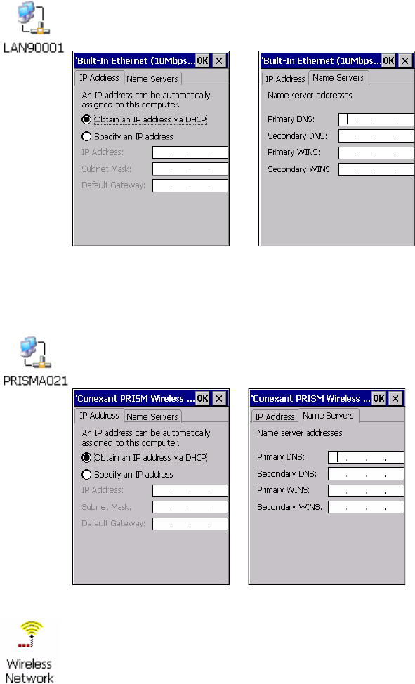
Chapter 5 — Network Support
110 CK60 Series Handheld Computer User’s Manual
Ethernet Communications
Wireless 802.11 Communications
Tap Start > Settings > Network and Dial-up Connections, then double-
tap the LAN90001 connection icon to access and configure its properties.
Tap Start > Settings > Network and Dial-up Connections, then double-
tap the PRISMA021 connection icon to access and configure its properties.
To configure wireless 802.11 communications on the CK60 Computer,
tap Start > Settings > Control Panel, then double-tap the Wireless Net-
work icon to access the Profile Wizard for the 802.11b/g radio module. Go
to Chapter 3 “Configuring the CK60 Computer” for configuration infor-
mation.
IP Address Name Servers
IP Address Name Servers

Chapter 5 — Network Support
CK60 Series Handheld Computer User’s Manual 111
AutoIP/DHCP
Automatic Private IP Addressing (AutoIP) is enabled by default in Win-
dows CE. To remain compatible with other versions of Windows CE,
enable this setting. You can configure the registry settings in the following
to set the required AutoIP/DHCP behavior:
HKEY_LOCAL_MACHINE\Comm\PRISMNDS1\TcpIp
Other registry keys that can modify the behavior of AutoIP are as follows.
You can find the appropriate settings and behavior of each of the AutoInt-
erval, AutoIP, AutoMask, AutoSeed, and AutoSubnet keys in Microsoft
Help.
When a TCP/IP client cannot find a DHCP server, it generates an AutoIP
address from the 169.254.xxx.xxx block. The client then tries to check for a
DHCP server every 15 seconds and if a DHCP server is found, the client
drops the AutoIP address and uses the address from the DHCP server.
To disable AutoIP, set the AutoCfg registry entry to “0.” If a DHCP server
cannot be found, instead of using AutoIP, the system will display the
“Unable to obtain a server assigned IP address” message.
Note: If you try to disable AutoIP using a CAB file to set the registry value
for AutoIP, remember to set the EnableDHCP value to “1” to keep DHCP
enabled.
Note: Use DhcpRetryDialogue and DhcpMaxRetry registry settings to
extend the number of attempts that a DHCP client makes to get a DHCP
address.
Note: Change the AutoInterval registry key value to make the client retry
more often to obtain a DHCP address.
Chapter 5 — Network Support
112 CK60 Series Handheld Computer User’s Manual

CK60 Series Handheld Computer User’s Manual 113
6Bar Code Symbologies
This appendix contains a brief explanation of some of the bar code symbol-
ogies that the CK60 Handheld Computer decodes and explains some of the
general characteristics and uses of these bar code types.
The CK60 Computer recognizes a number of the most widely used bar
code symbologies. With bar code symbologies, like languages, there are
many different types. A bar code symbology provides the required flexibil-
ity for a particular inventory tracking system.
A symbology may be for particular industries, such as food and beverage,
automotive, railroad, or aircraft. Some of these industries have established
their own bar code symbology because other symbologies did not meet
their needs.
Without going into great detail on the bar code structure, note that no two
products use the same bar code. Each product gets a unique bar code.
Industries that use a particular type of bar code symbology have formed
regulating committees or are members of national institutes that issue and
keep track of bar codes. This ensures that each organization that contrib-
utes to a particular industry conforms to its standard. Without some form
of governing body, bar coding would not work.
Chapter 6 — Bar Code Symbologies
114 CK60 Series Handheld Computer User’s Manual
Codabar
Codabar was for retail price-labeling systems. Today it is widely accepted
by libraries, medical industries, and photo finishing services.
Codabar is a discrete, self-checking code with each character represented by
a stand-alone group of four bars and three intervening spaces.
Four different start or stop characters get defined and designated “a”, “b”,
“c”, and “d”. These start and stop characters are constructed using one wide
bar and two wide spaces. A complete Codabar symbol begins with one of
the start or stop characters followed by some number of data characters and
ending in one of the start or stop characters. It may also contain optional
check digit before each stop character.
Any of the start or stop characters may be used on either end of the symbol.
It is possible to use the 16 unique start or stop combinations to identify
label type or other information.
Since Codabar is variable-length, discrete, and self-checking, it is a versatile
symbology. The width of space between characters is not critical and may
vary significantly within the same symbol. The character set consists of “0”
through “9”, “-”, “$”, “:”, “/”, “.”, and “+”.
The specific dimensions for bars and spaces in Codabar optimize perfor-
mance of certain early printing and reading equipment. Codabar has 18
different dimensions for bar and space widths. So many different dimen-
sions often result in labels printed out of specification and cause Codabar
printing equipment to be more expensive.
Codablock
Codablock is a stacked symbology from ICS Identcode-Systeme. It was
invented by Heinrich Oehlmann and was originally a stack of Code 39
symbols.
Each Codablock symbol contains from 1 to 22 rows. The number of char-
acters per row is a function of the x-dimension of the symbol. In other
words, each row can contain a variable amount of characters. Each symbol
has a start and stop bar group that extends the height of the symbol. Each
row has a two character row indicator, and the last row of the symbol has an
optional check digit. The symbol printing program must calculate not only
the number of rows needed as in the other stack symbologies, but also cal-
culate the number of characters per row and the print density necessary to
best fit the data into the Codablock symbol.
The code is a continuous, variable-length symbology that can encode the
Code 39 character set (10 digits, 26 letters, space, 6 symbols) and is as
dense as a Code 39 symbol at a given print density. For example, the maxi-
mum data density is 56 alphanumeric characters per square inch with a
symbol using an x-dimension of about 7.5 mils and a bar ratio of 2 to 1.
Chapter 6 — Bar Code Symbologies
CK60 Series Handheld Computer User’s Manual 115
Codablock A
Enables or disables decoding of Codablock A symbology. Codablock A is a
2D bar code that is an extension of Code 39.
Codablock F
The current version is Codablock F which is basically a stack of Code 128
symbols. A Codablock F symbol consists of between 2 and 44 rows, each
up to a maximum of 62 symbol characters wide. Each row can be read by a
standard code 128 reader and contains additional overhead information
relating to row numbering and symbol size to enable the decoded output
from each row to be re-assembled to reproduce the complete message in the
right sequence.
The advantage of this code is that it can be read by moving beam laser scan-
ners with very little modification. Codablock was adopted by German
blood banks for the identification of blood.
Code 11
Code 11 satisfies the requirements for a very high density, discrete numeric
bar code. The name Code 11 derives from 11 different data characters that
can be represented, in addition to a start or stop character.
The character set includes the 10 digits and the dash symbol. Each charac-
ter is represented by a stand-alone group of three bars and two intervening
spaces. Although Code 11 is discrete, it is not self-checking. A single print-
ing defect can transpose one character into another valid character. One or
two check digits obtain data security.
The specifications for Code 11 suggest that this code should have a narrow
element width of 7.5 mils. This results in an information density of 15
characters per inch.
Code 39
Code 39 (C39) is the most widely used symbology among the industrial bar
codes. Most major companies, trade associations, and the federal govern-
ment find this code to fit their needs. The main feature of this symbology is
the ability to encode messages using the full alphanumeric character set,
seven special characters, and ASCII characters.
Programming for this symbology can be for any length that the application
requires. The application program for the CK60 Computer handles sym-
bology at least one character but no more than 32 characters in length.
When programming the computer for Code 39, it is important to set the
symbology limit as close as possible (minimum and maximum bar code
lengths being scanned). Doing so keeps the computer bar code processing
time to a minimum and conserves battery power.
Chapter 6 — Bar Code Symbologies
116 CK60 Series Handheld Computer User’s Manual
Bar code readers can respond to Uniform Symbology Specification symbols
in non-standard ways for particular applications. These methods are not for
general applications, because of the extra programming required. Code 39
Full ASCII is one example of a symbology feature or operating mode, and is
defined as part of the symbology specification. This mode can be used for
general applications or any open system applications.
Code 39 Full ASCII Mode
If the bar code reader is programmed for the task, the entire ASCII charac-
ter set (128 characters) could be coded using two character sequences: a
symbol (“$”,“.”,“%”,“/”) followed by a letter of the alphabet.
Concatenated Code 39
If the first data character of a symbol is a space, the reader may be pro-
grammed to append the information contained in the remainder of the
symbol to a storage buffer. This operation continues for all successive sym-
bols that contain a leading space, with messages being added to the end of
previously stored ones. When a message is read which does not contain a
leading space, the contents are appended to the buffer, the entire buffer is
transmitted, and the buffer is cleared.
Code 93
The introduction of Code 93 provided a higher density alphanumeric sym-
bology designed to supplement Code 39. The set of data characters in Code
93 is identical with that offered with Code 39. Each character consists of
nine modules arranged into three bars and three spaces.
Code 93 uses 48 of the 56 possible combinations. One of these characters,
represented by a square, is reserved for a start or stop character, four are
used for control characters, and the remaining 43 data characters coincide
with the Code 39 character set. An additional single module termination
bar after the stop character concludes the final space.
Code 93 is a variable length, continuous code that is not self-checking. Bar
and spaces widths may be one, two, three, or four modules wide. Its struc-
ture uses edge-to-similar-edge decoding. This makes the bar code immune
to uniform ink spread, which allows liberal bar width tolerances.
Code 93 uses two check characters. Its supporters believes this makes it the
highest density alphanumeric bar code. The dual check digit scheme pro-
vides for high data integrity. All substitution errors in a single character are
detected for any message length.
Code 128
Code 128 (C128) is one of the newest symbologies used by the retail and
manufacturing industries. It responds to the need for a compact alphanu-
meric bar code symbol that could encode complex product identification.
Chapter 6 — Bar Code Symbologies
CK60 Series Handheld Computer User’s Manual 117
The fundamental requirement called for a symbology capable of being
printed by existing data processing printers (primarily dot-matrix printers)
that produce daily, work-in-progress, job, and product traceability docu-
ments. The ability to print identification messages between 10 and 32 char-
acters long, on existing forms and labels deemed an important requirement.
Code 128 uniquely addresses this need as the most compact, complete,
alphanumeric symbology available.
Additionally, the Code 128 design with geometric features, improves scan-
ner read performance, does self-checking, and provides data message man-
agement function codes.
Code 128 encodes the complete set of 128 ASCII characters without add-
ing extra symbol elements. Code 128 contains a variable-length symbology
and the ability to link one message to another for composite message trans-
mission. Code 128, being a double-density field, provides two numeric val-
ues in a single character.
Code 128 follows the general bar code format of start code, data, check
digit, stop code, and quiet code. An absolute minimum bar or space dimen-
sion of nine mils (0.010 inch minimum nominal
±
0.001 inch tolerance)
must be maintained.
Characters in Code 128 consist of three bars and three spaces so that the
total character set includes three start characters and a stop character.
UCC/EAN-128 Shipping Container Labeling is a versatile tool that can
ease movement of products and information. The Shipping Container
Labeling bar code can take any form and usually has meaning only within
the company or facility where applied.
Because this random data can get mistaken later for an industry standard
code format, the UCC and EAN chose a symbology uniquely identified
from these other bar codes. This standard is for maximum flexibility, to
handle the diversity of distribution in global markets by cost efficiency.
The UCC/EAN-128 Container Labeling specification calls for a FUNC1
to immediately follow the bar code’s start character. FUNC1 also follows
any variable-length application field. The specification also calls for the
computer to send “]C1” for the first FUNC1. The specification requires
that the computer send a “<GS>” (hex 1D) for subsequent FUNC1 codes
in the bar code.
Because “<GS>” is not compatible with computer emulation data streams,
the Uniform Code Council has been asked to change the specification. This
change is made to send the same three character sequence “]C1” to identify
the embedded FUNC1 codes.
This implementation should provide for clean application coding by identi-
fying the same sequences for the same scanned codes. If the communication
of bar code types is enabled, the Shipping Container Label codes precede
with a “J”. These strings will appear on the computer display. The applica-
tion may have to allow for strings longer than 48 characters (maximum
Chapter 6 — Bar Code Symbologies
118 CK60 Series Handheld Computer User’s Manual
length indicated in the specification). Actual length variance depends on
the number of variable-length data fields. Allowing for 60 characters should
be sufficient. Within the Code 128 specification, the computer can link bar
codes together. If this is to happen, allow for more characters (computer
limit is 100 characters).
The Application Identifier Standard, that is part of the UCC/EAN Ship-
ping Label concept, complements, rather than replaces, other UCC/EAN
standards. Most UCC/EAN standards primarily identify products.
Several industries expressed the need to standardize more than product
identification. The UCC/EAN Code 128 Application Identifier Standard
supplies this tool. The standard adds versatility for inter-enterprise
exchanges of perishability dating, lot and batch identification, units of use
measure, location codes, and several other information attributes.
For more detailed information on Code 128 UCC/EAN Shipping Label
bar code and Application Identifier Standard, refer to the UCC/EAN-128
Application Identifier Standard specification.
Data Matrix
Data Matrix is a high density 2D matrix code that can store a large amount
of information. It has excellent error correction abilities and is mostly used
for marking and tracking parts.
Data Matrix can store from 1 to about 2000 characters. The symbol is
square and can range from 0.001 inch per side up to 14 inches per side. As
an example of density, 500 numeric-only characters can encode in a 1-inch
square using a 24-pin dot matrix printer.
Data Matrix encodes product and serial number information on electrical
rating plates; marks surgical instruments in Japan; identifies lenses, circuit
boards, and other items during manufacturing.
EAN (European Article Numbering)
EAN symbology is similar to UPC symbology, except that it contains 13
characters and uses the first two to identify countries.
The EAN symbology is used in the retail environment throughout most of
Europe. Though similar to UPC symbology, these are not interchangeable.
EAN/UCC (Uniform Code Council) Composite
This component is not a stand-alone symbology. It is a 2D symbol
designed to act as a component of existing and new EAN/UCC System lin-
ear symbols. This is not designed to carry EAN.UCC System keys (these
are carried by the host linear symbol), however, it can carry any of the sys-
tem’s Application Identifiers. This symbology family is identified to pro-
vide encodation of item attribute data in a confined space.
Chapter 6 — Bar Code Symbologies
CK60 Series Handheld Computer User’s Manual 119
Interleaved 2 of 5 (I 2 of 5)
I 2 of 5 (Interleaved 2 of 5 Code) is an all-numeric symbology, widely used
for warehouse and heavy industrial applications. Its use has been particu-
larly prevalent in the automobile industry. The I 2 of 5 symbology can be
placed on smaller labels than what the standard UPC symbology requires.
I 2 of 5 also provides a little more flexibility on the type of material it can
print on. Interleaved 2 of 5 Code has its name because of the way the bar
code is configured.
I 2 of 5 bars and spaces both carry information. The bars represent the odd
number position digits, while spaces represent the even number position
digits. The two characters are interleaved as one. Messages encoded with
this symbology have to use an even number of characters since two numeric
characters always get interleaved together.
Matrix 2 of 5
Matrix 2 of 5 is a derivative of Code 11 and is a linear bar code limited to
ten digits and a start/stop character. Discrete but not self-checking. Matrix
2 of 5 is used with a single Modulo 10 check digit. Compared with Code
11 (using two check digits) and the other industrial symbologies, Matrix 2
of 5 is somewhat more subject to substitution errors and offers no particular
advantage.
MaxiCode
MaxiCode is a fixed-size code which holds up to 93 data characters. The
symbol is composed of a central bulls-eye locator and offset rows of hexago-
nal elements; the overall dimensions of the symbol are approximately 1.11
x 1.054 inches. Each element measures 0.035 x 0.041 inches.
Created by United Parcel Service, the MaxiCode symbol is for quick auto-
mated scanning of packages on high-speed conveyor lines (special cameras
can read a MaxiCode on a carton travelling at up to 500 feet per minute).
Micro PDF417
Micro PDF417 is derived from PDF417. The code has a limited set of
symbol sizes and a fixed level of error correction for each symbol size. Mod-
ule dimensions are user-specified so that the symbol may be printed with a
variety of printers. The symbology allows up to 150 bytes, 250 alphanu-
meric characters, or 366 numeric digits to be stored. This is done by speci-
fying one of three compaction modes: data, text or numeric. Text
Compaction mode permits all printable ASCII characters to be encoded
(values 32 to 126 inclusive) as well as selected control characters. Byte
Compaction mode permits all 256 possible 8-bit byte values to encode.
This includes all ASCII characters value 0 to 127 inclusive and provides for
Chapter 6 — Bar Code Symbologies
120 CK60 Series Handheld Computer User’s Manual
international character set support. Micro PDF417 is designed for applica-
tions where the symbol must be smaller than PDF417 will allow.
MSI Code (Variant of Plessey)
The MSI Plessey bar code is a variant of the Plessey bar code. It is a pulse-
width modulated non-self checking code, and is used primarily in store
shelf labeling. Each character consists of eight elements, four bars and four
spaces. The character set includes the digits 0 through 9. A Modulo 10
checksum is appended to the end of the code. For start and stop checks,
MSI employs a single bit pair of 1 as a start symbol and a single bit pair of 0
as a stop symbol. MSI reverses the 1-2-4-8 BCD pattern for bit pair weight-
ing to 8-6-2-1.
PDF417
The PDF417 symbology is a stacked 2D symbology that allows you to scan
across rows of code. Each row consists of start/stop characters, row identifi-
ers, and symbol characters, which consist of four bars and four spaces each
and contain the actual data. This symbology uses error correction symbol
characters appended at the end to recover loss of data.
PDF417 stores up to 1800 printable ASCII characters or 1100 binary char-
acters per symbol. The symbol is rectangular; the shape of the symbol is
adjusted to some extent by setting the width and allowing the height to
grow with the data. It is also possible to break large amounts of data into
several PDF417 symbols which are logically linked. There is no theoretical
limit on the amount of data that can store in a group of PDF417 symbols.
The capacity of PDF417 can be helpful in applications where the data must
travel with the labeled item, where a host database is not always available
for quick look-up. PDF417 is used for hazardous materials labeling; storing
technical specifications, and calibration data on electronic instruments;
encoding fingerprints and photographs on drivers’ licenses.
The maximum data density is determined by the smallest elements which
can be reliably printed and scanned. Using the smallest recommended ele-
ment size of 0.0075 inch wide and 0.010 inch high, the maximum data
density in the binary mode is 686 bytes per square inch (106.2 bytes per
square centimeter). In the printable ASCII mode the density is 1144 char-
acters per square inch (177.2 characters per square centimeter).
Plessey
Plessey finds its origin in the pulse width modulated (PWM) code devel-
oped in England. It is widely used for shelf markings in grocery stores.
Pulse width modulated codes represent each bit of information by a bar and
space pair. A zero bit consists of a narrow bar followed by a wide space,
while a one bit consists of a wide bar followed by a narrow space. It is
Chapter 6 — Bar Code Symbologies
CK60 Series Handheld Computer User’s Manual 121
mainly a numeric symbology (0-9) with six extra characters available for
assigning any symbol or letter desired.
Plessey codes employ a variety of check characters and a polynomial–based
Cyclic Redundancy Check (CRC). For start and stop characters, Plessey
employs a 1101 and previously used a 0101.
This symbology is very limited about what information can be encoded. It
is not considered for new applications.
QR Code (Quick Response Code)
QR Code is a 2D matrix symbology containing dark and light square data
modules. It has position detection patterns on three of its four corners and
features direct encodation of the Japanese Kana-Kanji character set. A 2D
imaging device such as a CCD camera is necessary to scan the symbology.
QR Code is designed with selectable levels of error correction. It supports
industry standard escape sequences to define international code pages and
special encodation schemes. QR Code is used for small item marking appli-
cations using a wide variety of printing and marking technologies. This
document includes descriptions of the character encodation, symbol struc-
ture, reference decode algorithm, and symbol quality measurements for QR
Code.
RSS (Reduced Space Symbology)
The EAN.UCC RSS family has three linear symbologies to use with the
EAN.UCC system. Usage is restricted and subject to compliance with the
EAN International/UCC rules and registration procedures.
RSS 14
RSS 14 encodes the full 14-digit EAN.UCC item identification in a linear
symbol scanned omnidirectionally by suitably programmed POS scanners.
RSS Expanded
RSS Expanded encodes EAN.UCC item identification plus supplementary
AI element strings such as weight and “best before” date in a linear symbol
that can be scanned omnidirectionally by programmed POS scanners.
RSS Limited
RSS Limited encodes a 14-digit EAN.UCC item identification with Indi-
cator digits of zero or one in a linear symbol for use on small items that is
not scanned at the POS.
Chapter 6 — Bar Code Symbologies
122 CK60 Series Handheld Computer User’s Manual
Telepen
Telepen was devised by George Sims, Managing Director of SB Electronic
Systems Limited, in early 1972, this is the only symbology to directly repre-
sent the full ASCII character set without shift characters.
Telepen carries the double-density numeric-only mode and is very com-
pact. The Telepen symbol is up to 8 ASCII characters or16 digit per inch,
and is easy to print. It has a fixed 3:1 ratio, with a tolerance at least 0.4x.
This symbology is extremely secure, with negligible risk of misreading. It is
supported by most leading manufacturers.
UPC (Universal Product Code)
The UPC (Universal Product Code) is the symbology used throughout the
grocery and retail industries. This bar code symbology contains two pieces
of numerical information encoded on the bar code, producer identification,
and product identification information.
The UPC symbol is 12 characters long. The first character of the UPC
symbol is a number system character, such as “0” for grocery items and “3”
for drug- and health-related items. This symbology is for retail environ-
ments such as grocery, convenience, and general merchandise stores.
Some retail items are so small that a standard UPC bar code cannot fit on
the packaging. When this occurs there is a shorter version of the UPC sym-
bology, referred to as UPC-E. UPC-E is six characters long (eight including
number system and check digit), about half of a standard UPC bar code.

Corporate Headquarters
6001 36th Avenue West
Everett, Washington 98203
U.S.A.
tel 425.348.2600
fax 425.355.9551
www.intermec.com
CK60 Handheld Computer with Windows CE 5.0 User's Manual
*961-054-037A*
P/N 961-054-037A