Intermec Technologies ABTM3-2 ABTM3-2 User Manual Product Profile
Intermec Technologies Corporation ABTM3-2 Product Profile
UserManual.wiki
>
Intermec Technologies
>
ABTM3-2 User Manual
>
Product Profile
Contents
1.
Manual Insert with Compliance Statements
2.
Product Profile
Product Profile
Navigation menu
Upload a User Manual
Namespaces
Wiki Guide
HTML
PDF
Info
Views
User Manual
Discussion / Help
Navigation
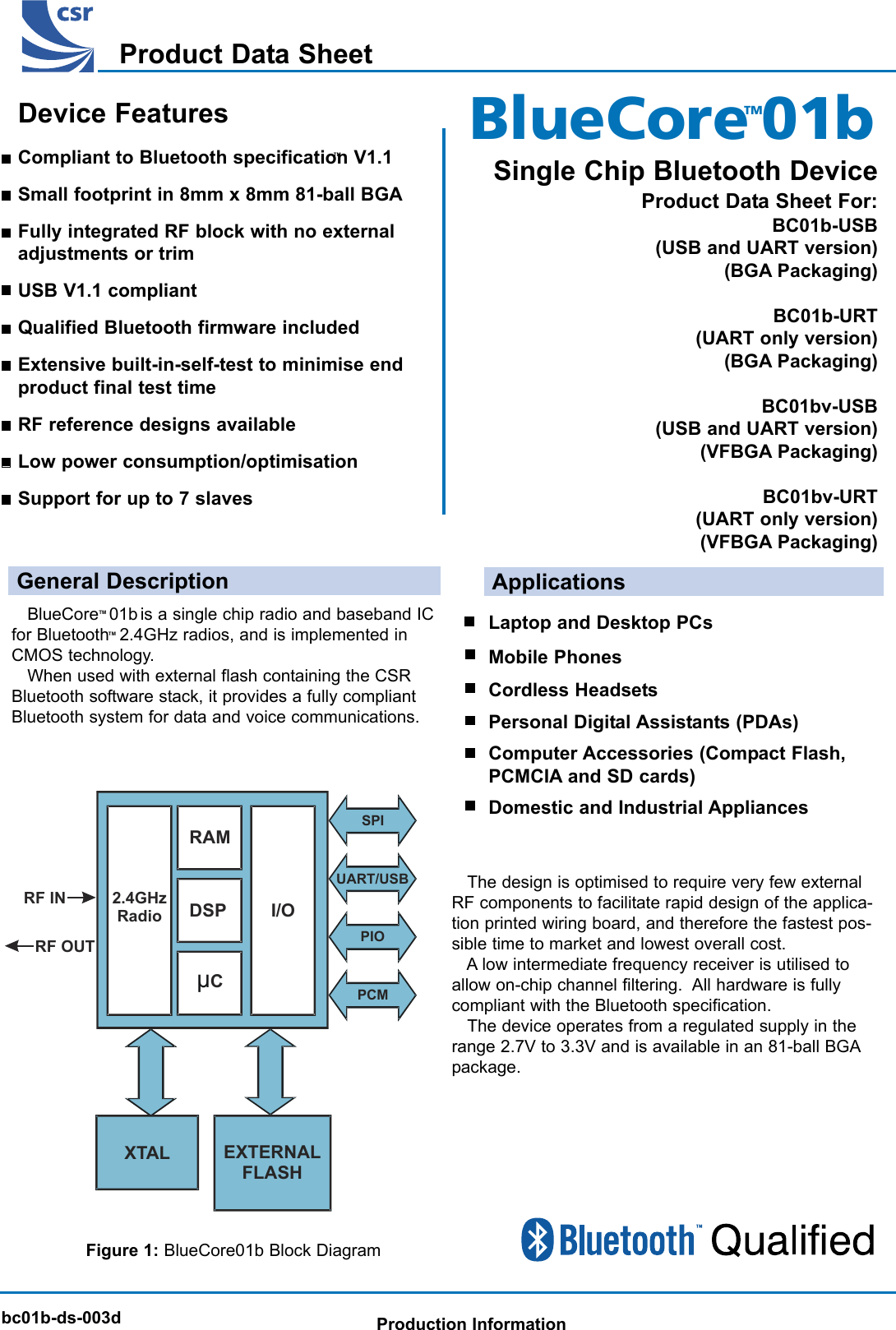
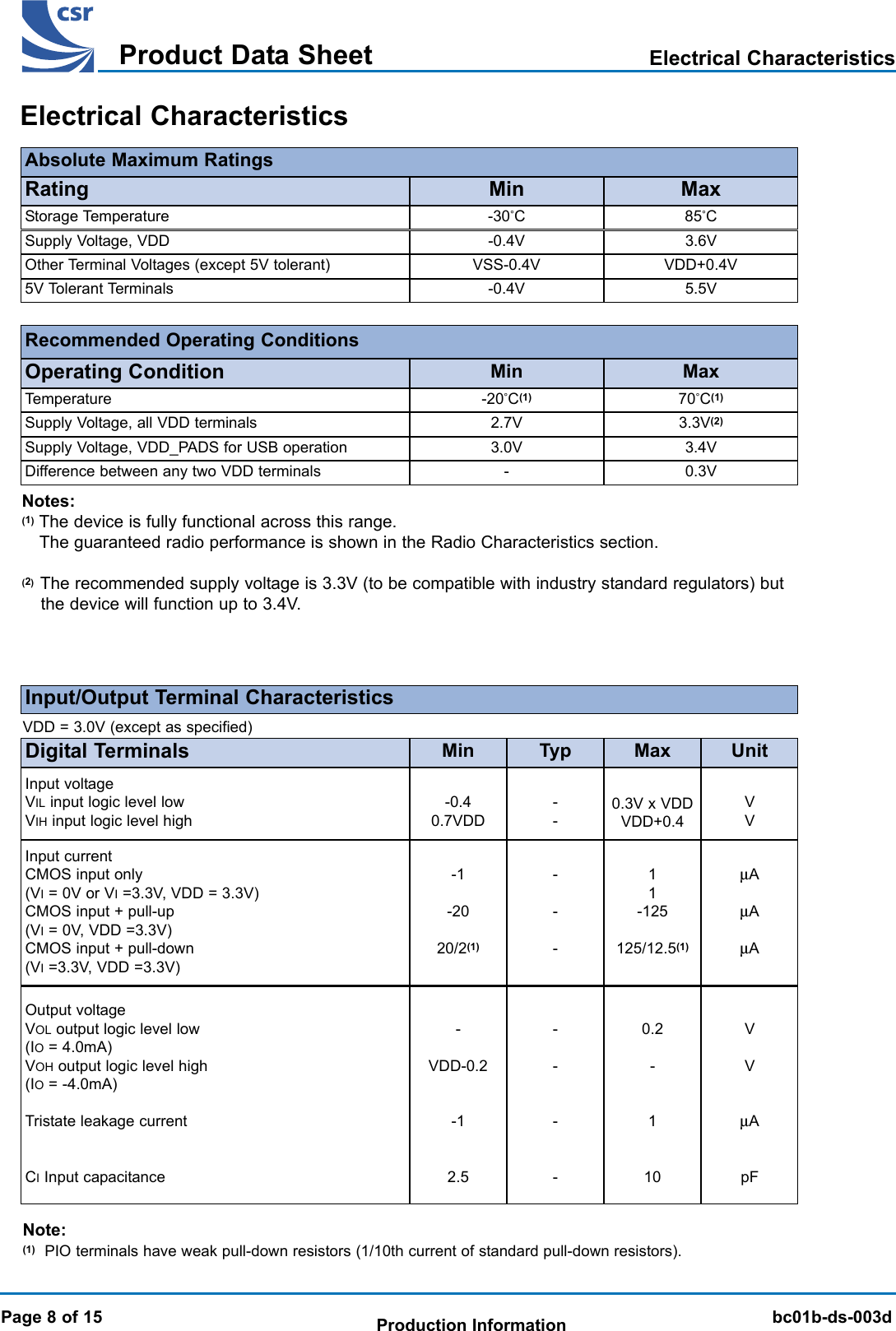
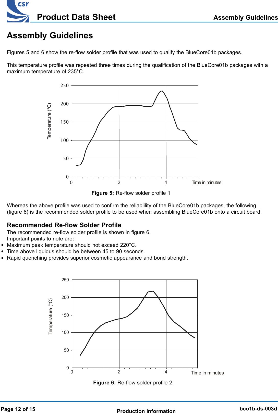
![BlueCore 01b Product Data SheetTMbc01b-ds-003dProduct Data SheetProduction Information Page 3 of 15MicrocontrollerInterruptcontrollerEventtimerRISCmicrocontrollerParallelI/OPIO[2]USB_PULL_UPPIO[3]USB_WAKE_UPPIO[4]USB_ONPIO[5]/USB_DETACHPIO[6]PIO[7]VSS_MEMVSS_PADSVSS_COREBaseband DSPSPI_CSBSPI_CLKSPI_MOSISPI_MISOPCM_OUTPCM_INPCM_SYNCPCM_CLKUART_TXUART_RXUART_RTS/USB_D+UART_CTS/USB_D-AudioPCMinterfaceUART/USBSynchronousserialinterfaceMemorymanagementunitBurstmodecontrollerRAMMemorymappedcontrol/statusregistersPhysicallayerDSPhardwareengineRESETTEST_ATEST_BSCAN_ENVDD_MEMVDD_PADSVDD_COREVREGXTAL_OUTXTAL_INVDD_VCOClockgeneratorV regulatorVDD_RADIORSSIPIO[0]/RXENRF_INTX_ATX_BPIO[1]TXENPAlevelcontrolPA DACIQ DEMODRF synthesiser/N/N+1TuneLOOP_FILTERADCDemodulatorVSS_VCOVSS_RADIO+45-45RF ReceiverRF TransmitterIQ MODTX_PWRRF SynthesiserFrefExternalmemory driverCSBA[17:0]D[15:0]WEB1816REBLNAFigure 2: BlueCore01b Device DiagramDevice DiagramDevice Diagram](https://usermanual.wiki/Intermec-Technologies/ABTM3-2.Product-Profile/User-Guide-276974-Page-3.png)
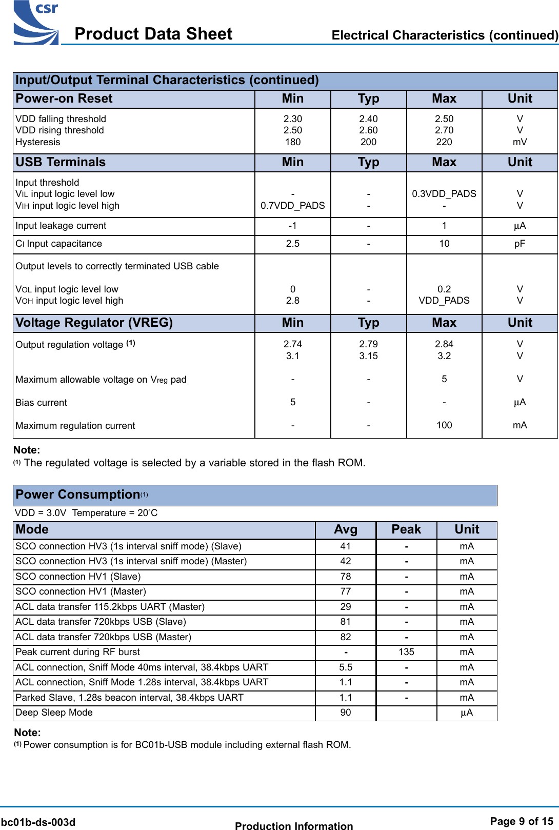
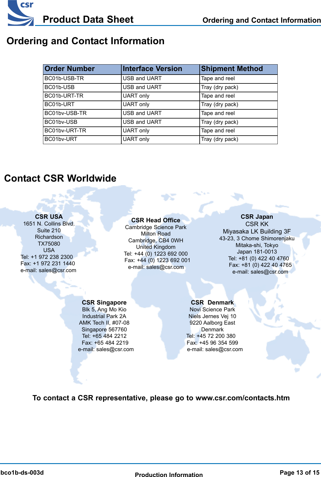
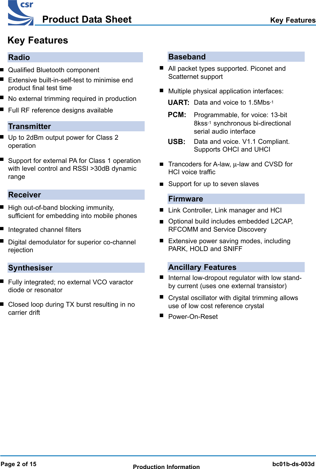
![BlueCore 01b Product Data SheetTMbc01b-ds-003dProduct Data SheetProduction InformationPage 4 of 15VSS_PADS VDD_PADS UART_TX UART_RTS / USB_D+ VDD_MEM VSS_MEM WEB A[0] A[1]PIO[3] /USB_WAKE_UPPIO[4] / USB_ON UART_RX UART_CTS / USB_D- PCM_SYNC A[6] A[3] A[4] A[2]RESETPIO[2] / USB_PULL_UPSPI_MISO SPI_MOSI PCM_IN D[15] A[9] A[7] A[5]TX_PWR PIO[0] /RXEN SPI_CLK SPI_CSB PCM_CLK A[12] A[11] A[10] A[8]RF_IN VSS_RADIO PCM_OUT SCAN_EN NC D[13] A[15] A[13] A[14]TX_B VSS_RADIO PIO[1] /TXENPIO[5] / USB_ DETACHD[11] D[12] D[10] A[17] CSBTX_A VDD_RADIO PIO[6] PIO[7] D[14] D[7] D[9] A[16] REBVSS_VCO LOOP_FILTER TEST_B VDD_CORE VSS_CORE D[6] D[4] D[3] D[0]VDD_VCO TEST_A XTAL_OUT XTAL_IN VREG D[8] D[5] D[2] D[1]123456789ABCDEFGHJFigure 3: BlueCore01b Device PinoutDevice Pinout DiagramNote: (1) = Not connected.Device Pinout DiagramOrientation from top of device(1)](https://usermanual.wiki/Intermec-Technologies/ABTM3-2.Product-Profile/User-Guide-276974-Page-4.png)
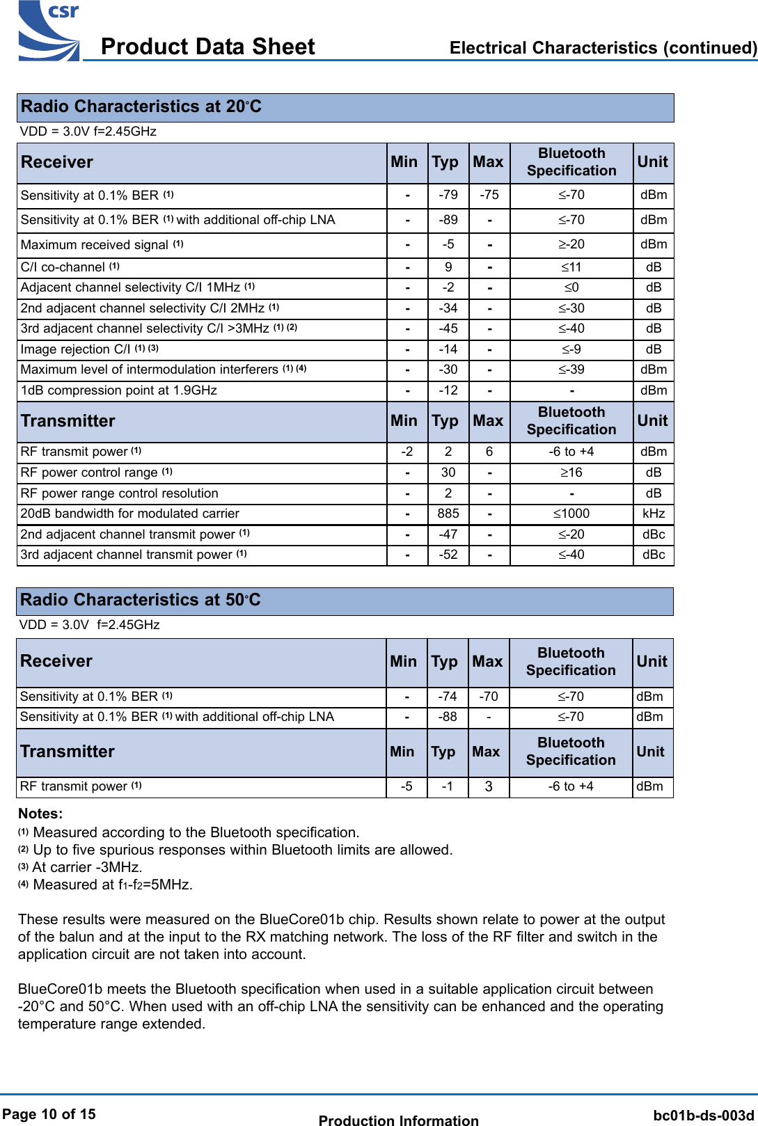
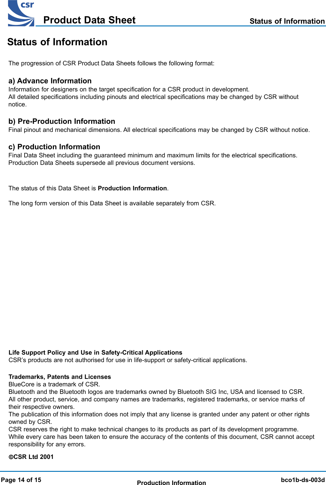
![BlueCore 01b Product Data SheetTMbc01b-ds-003dProduct Data SheetProduction Information Page 5 of 15Terminal Name Pad Type DescriptionBallRF_IN - Receiver RF inputE1Transmitter RF outputG1RadioTX_B - Transmitter RF output (complement of TX_A)F1PIO[1] / TXEN Bidirectionalpulled down Control output for external switch or PA (if fitted)F3PIO[0] / RXEN Bidirectionalpulled downControl output for external switch or LNA(if fitted)D2TX_PWR Current DAC output to set external PA levelD1XTAL_IN Sense for crystal or external clock inputJ4XTAL_OUT Drive for crystalJ3Synthesiser and OscillatorA[17:0] Address bus for external memory(1)WEB Write enable for external memory (active low)A7Data bus for external memoryExternal Memory PortREB Read enable for external memory (active low)G9CSB Chip select for external memory (active low)F9PCM_SYNC Synchronous data strobeB5PCM_IN Synchronous 8kss-1 data inputC5Synchronous data clockD5PCM InterfacePCM_OUT Synchronous 8kss-1 data outputE3--LOOP_FILTER Synthesiser external loop filterH2CMOS outputD[15:0] BidirectionalCMOS outputCMOS outputCMOS output(1)Bidirectionalpulled downCMOS inputpulled downCMOS output-TX_A -Current DACPCM_CLK Bidirectionalpulled downNote:(1) See Address and Data Bus tables at the end of this section.Device Terminal FunctionsDevice Terminal Functions](https://usermanual.wiki/Intermec-Technologies/ABTM3-2.Product-Profile/User-Guide-276974-Page-5.png)
![BlueCore 01b Product Data SheetTMbc01b-ds-003dProduct Data SheetProduction InformationPage 6 of 15SPI clockD3Test and DebugSPI_MOSI CMOS input, 5V tolerant pulled down SPI data inputC4UART_TX UART data outputA3UART_RX UART data inputB3UART or USB(1)UART_RTS / USB_D+ CMOS output UART ready to send / USB D+A4PIO[2] / USB_PULL_UP Bidirectionalpulled down USB pull-up (via 1.5kΩ resistor to D+)C2UART_CTS / USB_D- CMOS input UART clear to send / USB D-B4CMOS outputPIO[3] / USB_WAKE_UP Bidirectionalpulled downOutput goes high to wake up PC when in USBmodeB1Terminal Name Pad Type DescriptionBallCMOS input, 5V tolerantpulled downPIO[4] / USB_ON Bidirectionalpulled downUSB on (input senses when VBUS is high,wakes BlueCore01b)B2PIO[5] / USB_DETACH Bidirectionalpulled down Chip detaches from USB when this line is highF4Device Terminal Functions (continued)SPI_CLK CMOS input, 5V tolerant pulled downSPI_CSB SPI chip selectD4CMOS input, 5V tolerant pulled upTEST_A -Analog test port AJ2SPI_MISO CMOS output Tristate SPI data outputC3PIO[0] /RXEN Bidirectionalpulled downPIO[2] /USB_PULL_UP Bidirectionalpulled down Input/Output port or USBC2PIO[1] /TXEN Bidirectionalpulled down Input/Output port or high when TX is enabledF3PIO PortPIO[3] /USB_WAKE_UP Bidirectionalpulled downRESET CMOS input with weakinternal pull-down ResetC1Input/Output port or high when RX is enabledD2Input/Output port or USBB1TEST_B -Analog test port BH3SCAN_EN CMOS input with weakinternal pull-down For test purposes only (leave unconnected)E4PIO[4] /USB_ON Input/Output port or USBB2PIO[5] /USB_DETACH Input/Output port or USBPIO[7] Bidirectionalpulled down Input/Output portG4Bidirectionalpulled downBidirectionalpulled down F4PIO[6] Bidirectionalpulled down Input/Output portG3Note:(1) BC01b-USB supports both USB and UART (but not simultaneous operation). BC01b-URT supports UART only.](https://usermanual.wiki/Intermec-Technologies/ABTM3-2.Product-Profile/User-Guide-276974-Page-6.png)
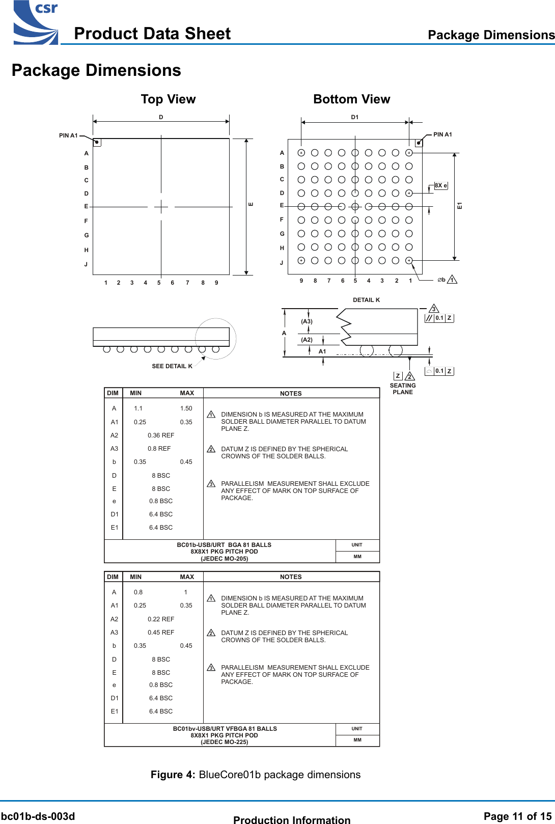
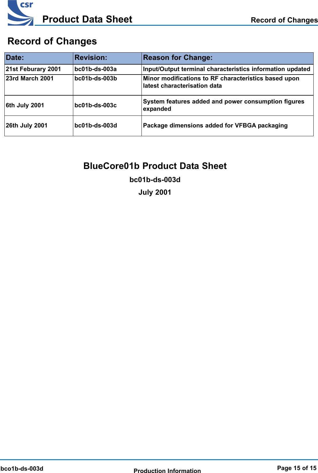
![BlueCore 01b Product Data SheetTMbc01b-ds-003dProduct Data SheetProduction InformationTerminal BallA[1]A[0]Address LinesTerminal BallD[1] J9D[0] H9Data BusA[4]A[5]A[6]A[8]A[9]D[2] J8D[3] H8D[4] H7D[5] J7D[6] H6A8A9B8C9B6D9C7A[10] D8A[11] D7A[12] D6A[13] E8A[14] E9A[15] E7A[16] G8A[17] F8D[7] G6D[8] J6D[9] G7D[10] F7D[11] F5D[12] F6D[13] E6D[14] G5D[15] C6VREG LDO voltage regulator output to external passtransistorJ5Power Supplies and Control-VDD_CORE VDD For internal digital circuitryH4Terminal Name Pad Type DescriptionBallVDD_RADIO For RF circuitryG2VDDVDD_VCO For VCO and synthesiserVDD_PADS For all Input/Output except memory portA2VDDVDD_MEM For external memory portA5VDDVSS_CORE For internal digital circuitryH5VSSVSS_RADIO For RF circuitryF2, E2VSSVSS_VCO For VCO and synthesiserH1VSSVSS_PADS For Input/Output except memory portA1VSSVSS_MEM For external memory portA6VSSPage 7 of 15Device Terminal Functions (continued)J1VDDA[2] B9A[3] B7A[7] C8](https://usermanual.wiki/Intermec-Technologies/ABTM3-2.Product-Profile/User-Guide-276974-Page-7.png)