Intermec Technologies BTM311 BTM311 User Manual 943 002
Intermec Technologies Corporation BTM311 943 002
Contents
User Manual
IP4 Portable
RFID Reader
Instructions
chg photo
chg title to IP30
all subject to change to
reflect IP30 use.
Dave Fry
Sr. EMC Engineer
Feb. 28, 2008
ii IP4 Portable RFID Reader Instructions
Contents
Introducing the IP4 Portable RFID Reader . . . . . . . . . . . . . 3
What You Get . . . . . . . . . . . . . . . . . . . . . . . . . . . . . . . . . . . 3
Using the IP4 . . . . . . . . . . . . . . . . . . . . . . . . . . . . . . . . . . . . 3
Charging and Installing the Battery . . . . . . . . . . . . 3
Attaching Your IP4 to a 700 Color. . . . . . . . . . . . . 5
(Optional) Configuring Your IP4 as a
Keyboard Wedge . . . . . . . . . . . . . . . . . . . . . . . . 6
Reading an RFID Tag . . . . . . . . . . . . . . . . . . . . . . 8
Understanding the IP4 LEDs . . . . . . . . . . . . . . . . . . . . . . . . 9
Specifications . . . . . . . . . . . . . . . . . . . . . . . . . . . . . . . . . . . 10
all subject to change to
reflect IP30 use.
Dave Fry
Sr. EMC Engineer
Feb. 28, 2008
IP4 Portable RFID Reader Instructions 3
Introducing the IP4 Portable RFID Reader
The IP4 Portable RFID Reader is an accessory handle for the
700 Series Color mobile computers. Together, the IP4 and
700 Color provide a high-performance mobile RFID solution
that allows you to bring the read/write device to the tagged
product rather than moving tagged products past a fixed reader.
What You Get
• IP4 Portable RFID Reader
• Battery (Model AB12)
• Product documentation
Using the IP4
To use the IP4, you need to perform these steps:
1Charge and install the battery.
2Attach your IP4 to a 700 Color.
3(Optional) Configure your IP4 as a keyboard wedge.
4Read an RFID tag.
These instructions describe each step.
Charging and Installing the Battery
To charge the IP4 battery, you need the Dual Pack Battery
Charger (Model AC12).
To charge the IP4 battery
• Insert the battery into a slot on the AC12 battery charger.
A fully discharged battery charges in less than 4 hours.
del 700 terminal
mention terminals
CK61
CN3
CN3e
4 IP4 Portable RFID Reader Instructions
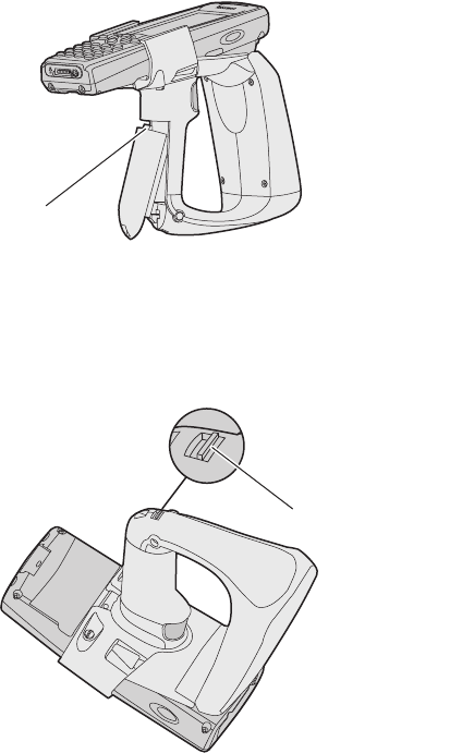
To install the battery
1Insert the battery tab on the top of the battery into the IP4.
2Firmly press the bottom of the battery onto the IP4 until the
battery snaps into place.
To remove the battery
• Push the battery release latch on the bottom of the IP4.
Battery tab
Battery release latch
replace diagrams with
IP30
IP4 Portable RFID Reader Instructions 5
Attaching Your IP4 to a 700 Color
Your IP4 uses Infrared Data Association (IrDA) to communicate
with the 700 Color. The lightpipe in the IP4 helps communicate
the IrDA signal between the 700 Color and your IP4.
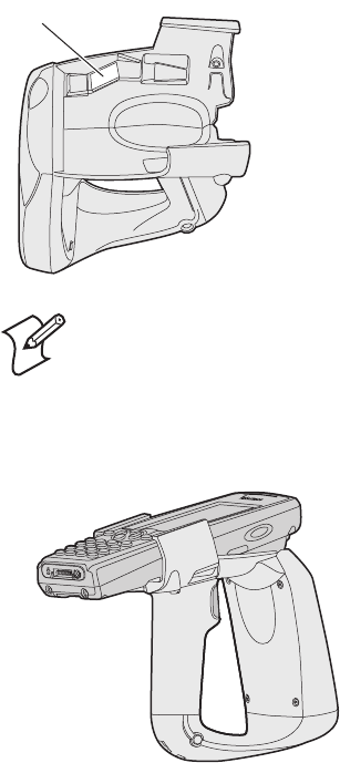
To attach your IP4 to a 700 Color
1Slide the 700 Color into the IP4 until it clicks into place.
Note: Do not remove the lightpipe from the IP4.
Lightpipe
chg diagrams
consider adding
seperate CK61 and
CN3 installed diagrams
6 IP4 Portable RFID Reader Instructions
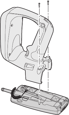
2Secure the retaining screws, making sure that they are inserted
straight into the 700 Color.
To remove your IP4 from a 700 Color
1Remove the two retaining screws.
2Hold the 700 Color at the display.
3While lifting the 700 Color up (away from the IP4), pull the
700 Color forward and out of the IP4.
(Optional) Configuring Your IP4 as a Keyboard Wedge
You can configure your IP4 as a keyboard wedge to allow the 700
Color to receive data from your IP4 as it would from a keyboard.
To use your IP4 as a keyboard wedge, the 700 Color and your
IP4 must meet these requirements:
• The 700 Color must have at least 64MB of flash ROM.
• The fifth character in the configuration number (CN) found
on the back of the 700 Color must not be a 4 or 5. For
example:
•751B6xxxx meets this requirement.
•760A4xxxx does not meet this requirement.
chg or del
IP30 does not require
screws for attachment
del
keyboard wedge
discussion

IP4 Portable RFID Reader Instructions 7
• The 700 Color must be running one of these operating
systems (OS):
• 4.95.1 or later Prem (Premium)
• 4.96.4 or later GSM Phone
• If the fourth character in the configuration number (CN) of
your IP4 is an “A”:
• The 700 Color must be running IVA 4.03.35.1043 or
later.
• Your IP4 must be running firmware version 5.19 or later.
• If the fourth character in the configuration number (CN) of
your IP4 is an “B”:
• The 700 Color must be running IVA 4.03.35.1050 or
later.
• Your IP4 must be running firmware version 7.16 or later.
To configure your IP4 as a keyboard wedge
1Fully charge your IP4 battery and attach your IP4 to a 700
Color.
2On the 700 Color, start Intermec Settings.
3Select RFID > Reader 1, and select Enable Reader.
4Under Reader 1, select Reader Module > Ta g Typ e , and
select the type of RFID tag you are using.
5From the main Intermec Settings menu, select Device
Settings > Keypad > Scan Button Remapping > Handle
Trigg er, and select RFID.
6Save your settings.
Note: Use Intermec Settings to find the OS and IVA
versions of the 700 Color. For help, see the user’s
manual for the 700 Color.
edit for correct terminal config
no cell phone offering in
CK61
options limited for CN3
NO CDMA or GPRS radio

8 IP4 Portable RFID Reader Instructions
To test the keyboard wedge
1Start Microsoft Pocket Word.
2Read an RFID tag. For help, see the next section.
The RFID tag information appears in Pocket Word.
Reading an RFID Tag
You can scan at least six RFID tags per second with the IP4.
To read an RFID tag
1Position the front of the IP4 within 91 cm (3 ft) of an RFID
tag.
2Pull the trigger.
Note: Continuously reading tags with the IP4 may
cause the IP4 to overheat. If the IP4 temperature rises
above the maximum operating temperature, the IP4
will stop reading tags. If this occurs, let the IP4 cool
down until its temperature is within the operating
temperature range.
RF Exposure regulations limit exposure to radio
frequency (RF) radiation. To comply with these
regulations, operators of this device must maintain
a distance of at least 20 cm (8 in) from the cover on
the antenna assembly. (The cover on the antenna is
the dome-shaped surface.) While the device is on,
the operator’s body and parts of the body such as
eyes, hands, or head, must be 20 cm (8 in) or
farther from the cover of the antenna assembly.
Avertissement: Les réglementations sur les
expositions RF limitent l'exposition aux
rayonnements RF. Pour se conformer à ces
réglementations, les opérateurs de ce dispositif
doivent maintenir une distance minimale de 20 cm
du couvercle de l'antenne. (Le couvercle de
l'antenne est la surface bombée.) Lorsque l'appareil
est sous tension, le corps et les parties du corps
(yeux, mains, tête) de l'opérateur doivent être à au
moins 20 cm du couvercle de l'antenne.
RF safe distance may
need correction.
initial distance
repl 20 cm (8 in)
with
23 cm (9 in)
TBD
IP4 Portable RFID Reader Instructions 9
Understanding the IP4 LEDs
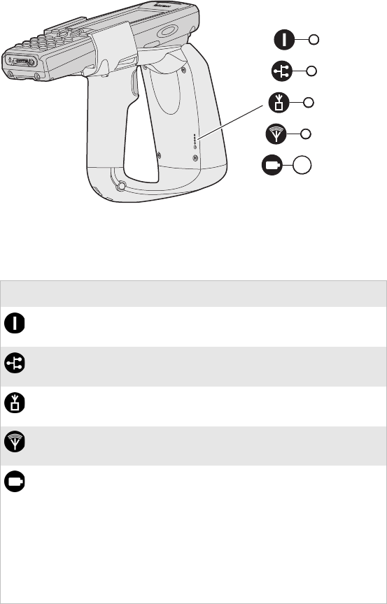
Your IP4 uses LEDs to indicate the status of certain operations.
IP4 LEDs: The IP4 LEDs are located on the back of the IP4.
IP4 LED Descriptions
Icon LED Description
Power (PWR) This LED is green when +5 power is
on and the IP4 is ready to read tags.
Host Communications
(HOST COMM)
This LED is green when data
communication with the host is active.
RF Power On (RF ON) This LED is green when RF power is
on.
Tag Communications
(TAG COMM)
This LED turns green after the IP4
successfully reads an RFID tag.
Battery
(BATT)
This LED indicates the status of the
battery:
• Red: The battery is low (less than
20% capacity).
• Green: The battery is fully charged
(more than 80% capacity).
• Orange: The battery is charged
(from 20% to 80% capacity).
LEDs
replace with
IP30 placements

10 IP4 Portable RFID Reader Instructions
Specifications
This section contains specifications for the IP4.
Environmental Specifications
Specification Value
Operating temperature 0°C to 50°C (32°F to 122°F)
Storage temperature -30°C to 70°C (-22°F to 158°F)
Relative humidity 5 to 95% non-condensing
869 MHz Frequency
Specification Value
Source type Single Channel
Frequency band 869.525 MHz
EIRP/ERP 0.5 watt ERP
Output power
1 W maximum
Minimum = 26.0 dBm
Typical = 26.5 dBm
Maximum = 27.0 dBm
Modulation 80%
Data Rate N/A
915 MHz Frequency
Specification Value
Source type Frequency hopper
Frequency band 902-928 MHz
EIRP/ERP 1 watt EIRP
Output power
1 W maximum
Minimum = 28.5 dBm
Typical = 29.5 dBm
Maximum = 30.0 dBm
Modulation 90%
Data Rate 38 to 44 Kbps

IP4 Portable RFID Reader Instructions 11
Performance
Specification Value
RFID tag identification
rate
At least six tags per second with one to ten
tags in the RF field, located at half the
maximum reading distances from the IP4
front panel.
RFID tag read distance 91 cm (3 ft)
RFID tag data
exchange rates
Read a tag containing 8 bytes of data within
50 ms.
Perform a verified write to tag at an average
rate of 75 ms per byte per tag.
Firmware Architecture
Specification Description
Firmware Communicates in Basic Reader Interface
(BRI) mode.
Protocol/Compatibility ANSI NCITS 256.2000 for API, part 2,
part 3-1
Reader Configuration Access Summary
Function Control Mechanism Responsible Party
Change Country
Code
Hardware key or
configuration tag
Factory or Intermec®
Field Technician
Download updated
firmware
Intermec-only
password
Remote or on-site field
technician
Setup, system
configuration not
secured at higher level,
such as change battery
or wake up default
Configuration file Customer System
Administrator

Patent Information
Product is covered by one or more of the following patents:
5,673,037; 5,729,697; 5,777,561; 5,828,318; 5,850,187;
5,912,632; 5,942,987; 5,995,019; 6,032,127; 6,121,878;
6,172,596; 6,286,762; 6,288,629; 6,422,476; 6,429,775;
6,525,648; 6,529,880; 6,608,551; 6,639,509; 6,812,841;
6,812,852; 6,919,793.
Patent Application 2002-0046173.
There may be other U.S. and foreign patents pending.
IP4 Portable RFID Reader Instructions
*943-002-004*
P/N 943-002-004
Worldwide Headquarters
6001 36th Avenue West
Everett, Washington 98203
U.S.A.
tel 425.348.2600
fax 425.355.9551
www.intermec.com
©
2007 Intermec Technologies
Corporation. All rights reserved.