Intermec Technologies IM4 IM4 User Manual IM4 Integration Guide

Intermec Technologies Corporation IM4 IM4 Integration Guide

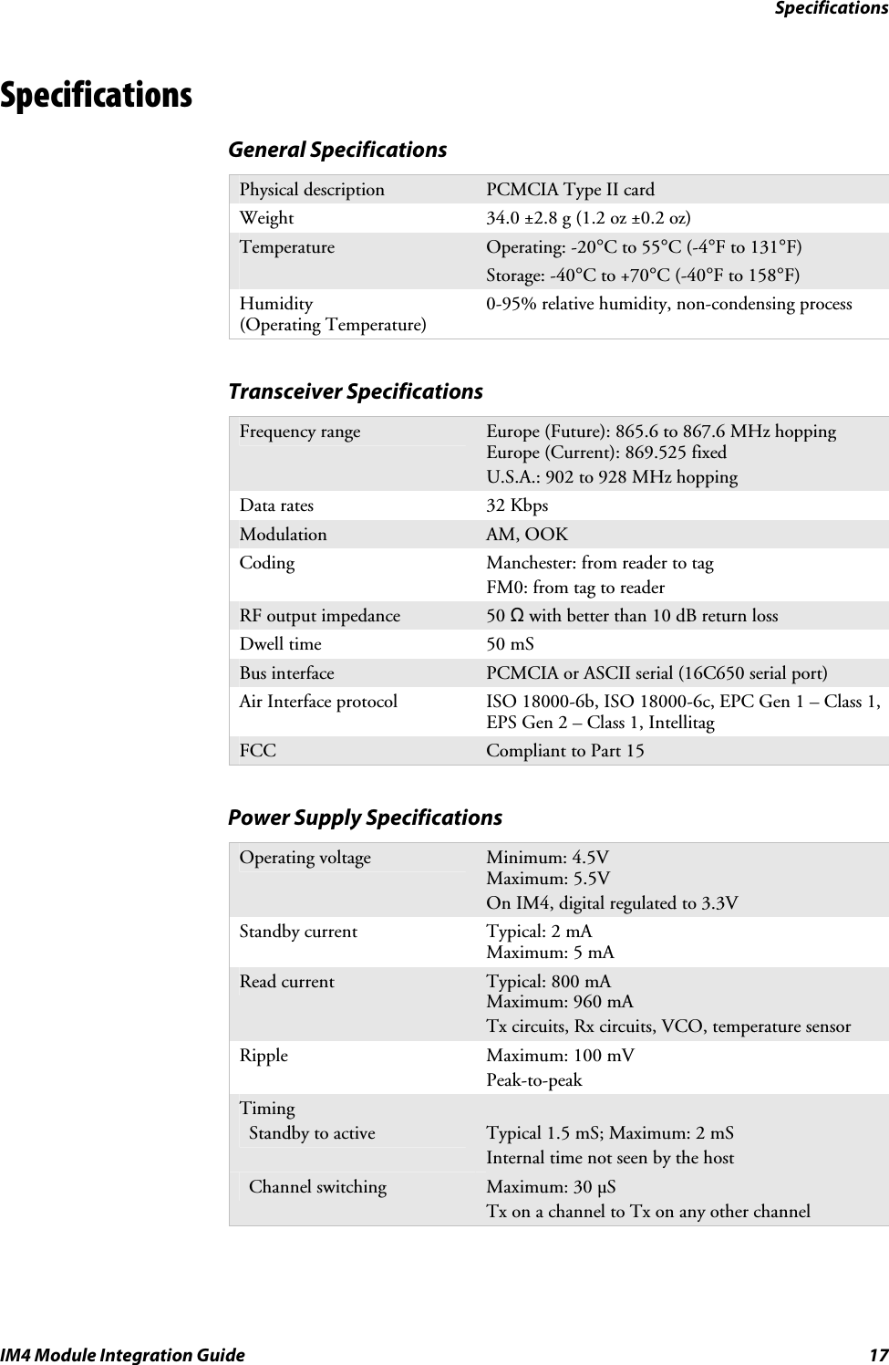
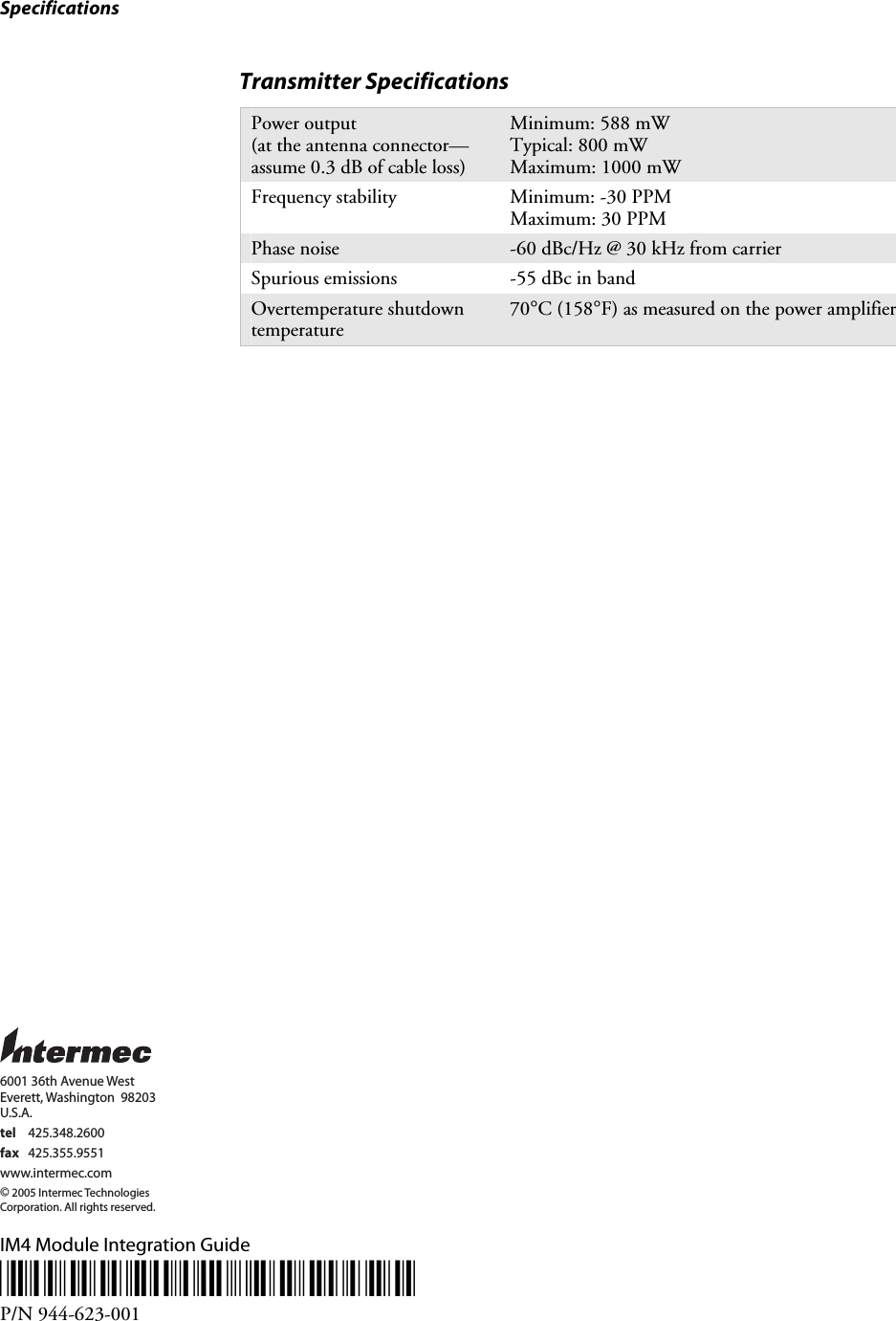
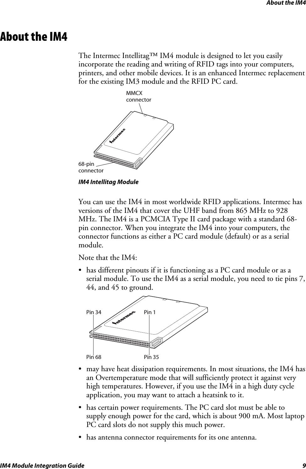
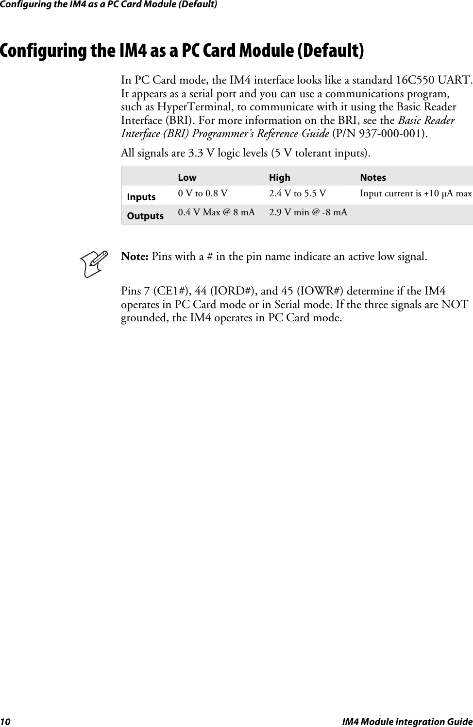
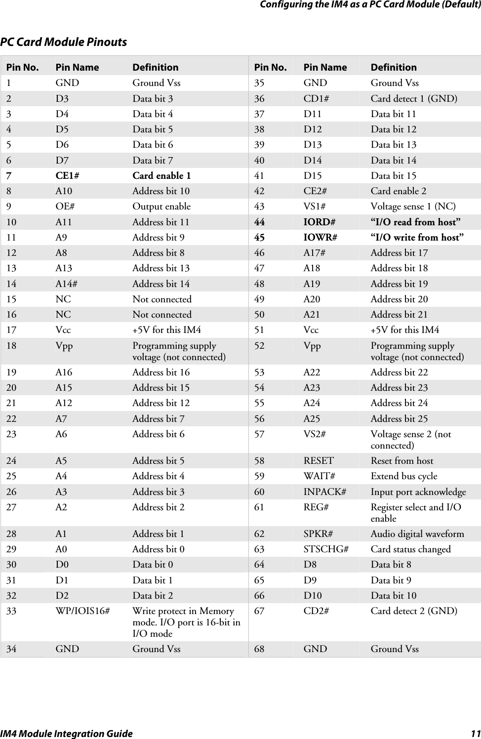
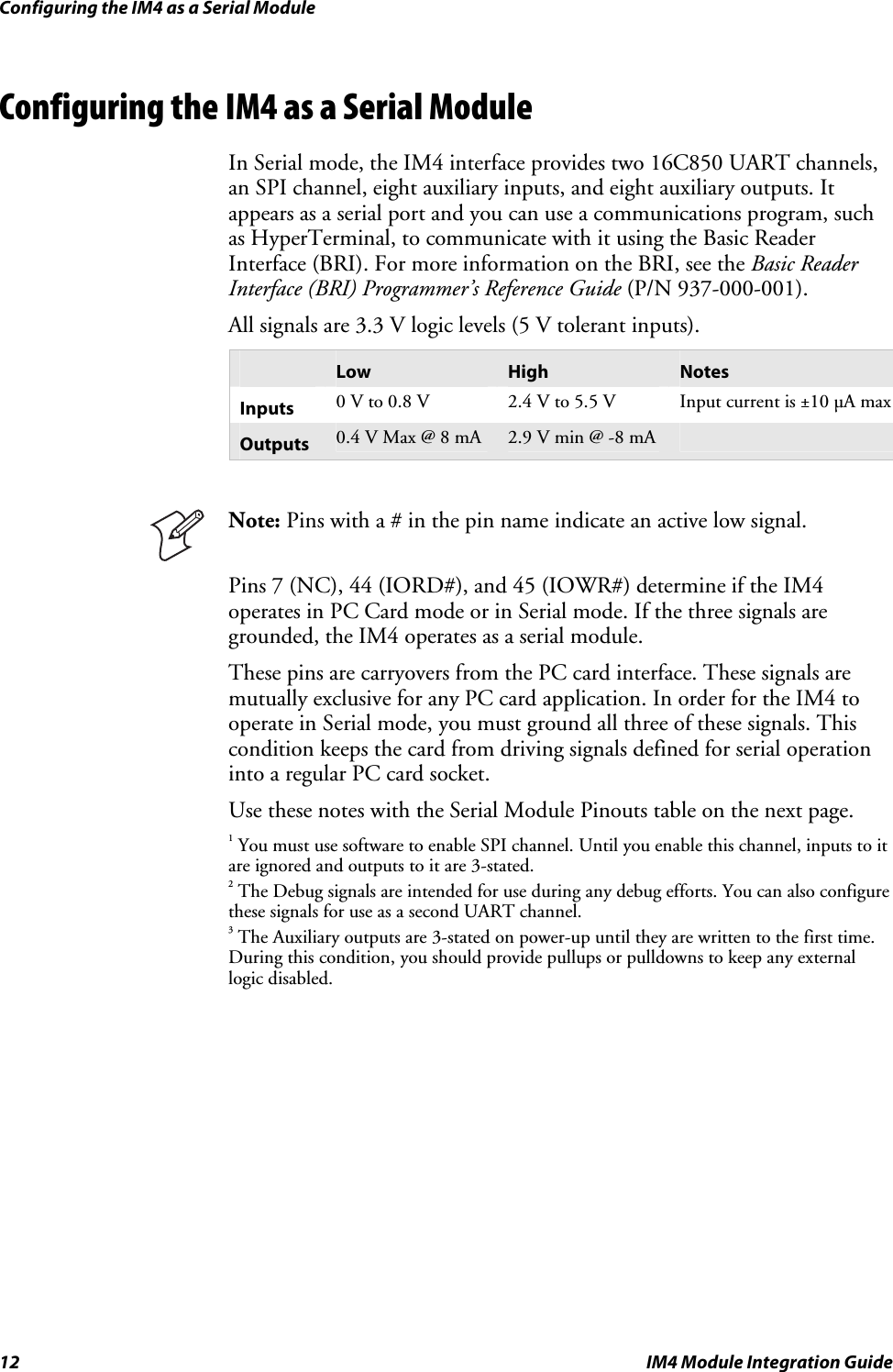
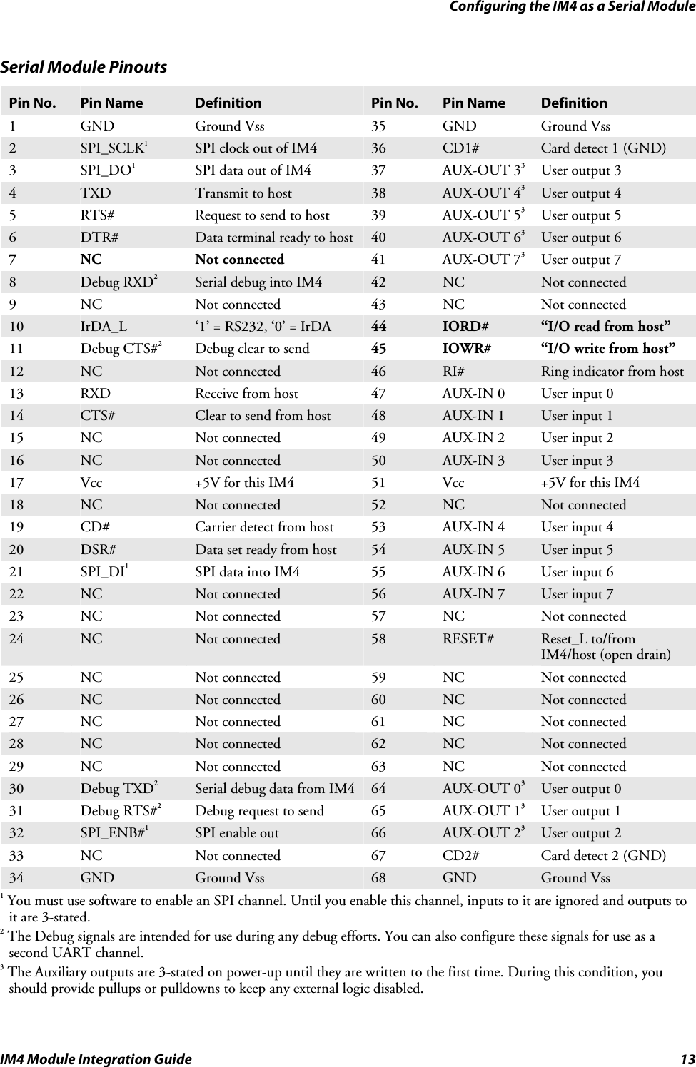
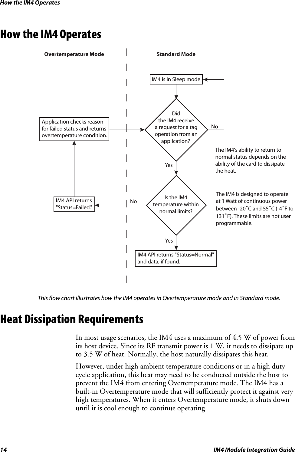
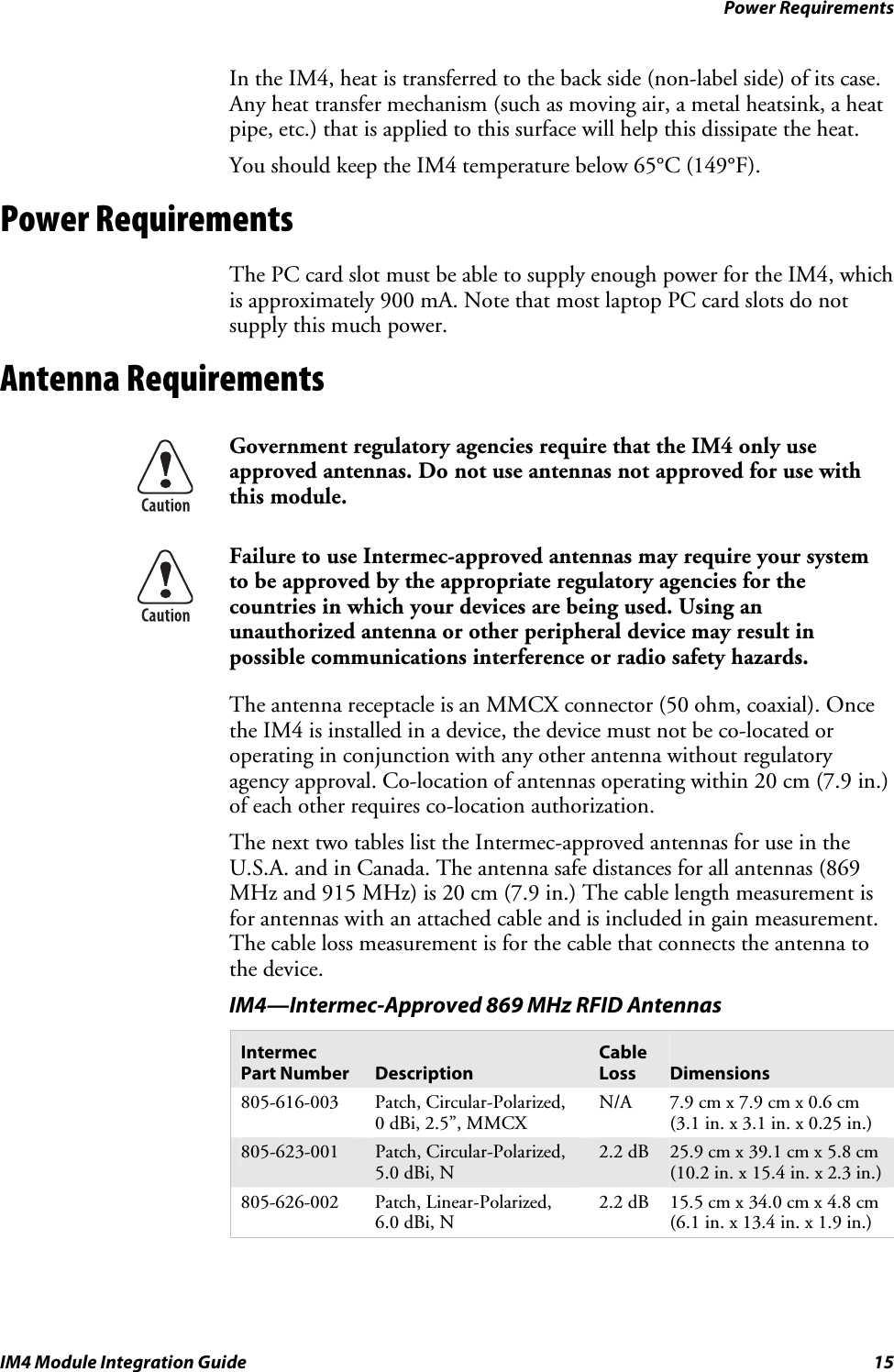
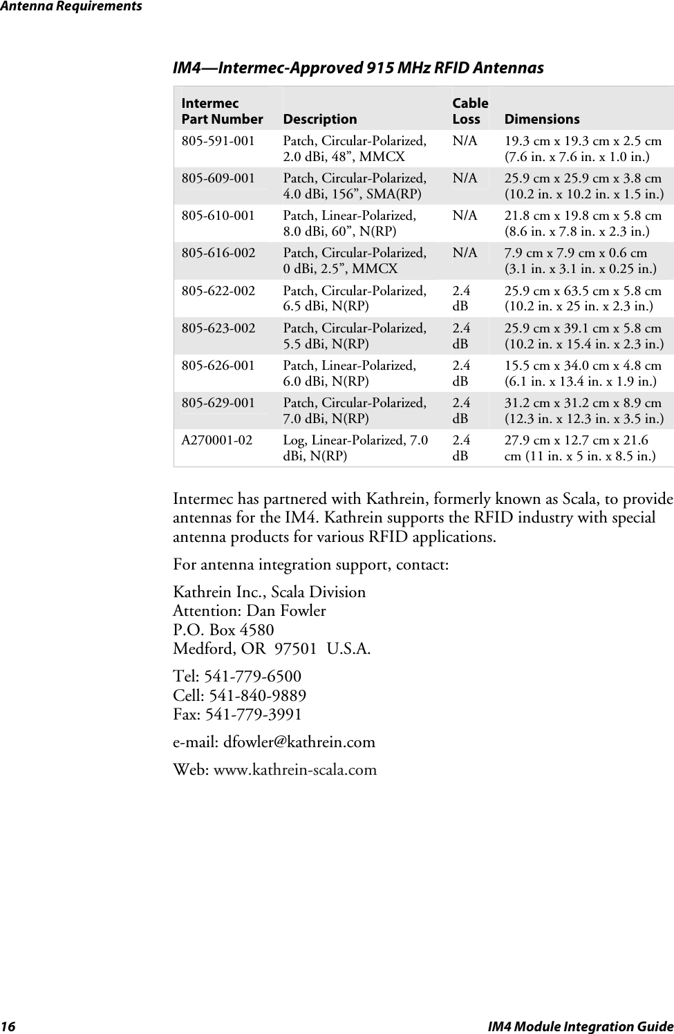
OEM Integration Guide

IM4 ModuleIntegration Guide
ii  IM4 Module Integration Guide Intermec Technologies Corporation Corporate Headquarters 6001 36th Ave. W. Everett, WA  98203 U.S.A. www.intermec.com  The information contained herein is proprietary and is provided solely for the purpose of allowing customers to operate and service Intermec-manufactured equipment and is not to be released, reproduced, or used for any other purpose without written permission of Intermec. Information and specifications contained in this document are subject to change without prior notice and do not represent a commitment on the part of Intermec Technologies Corporation. © 2005 Intermec Technologies Corporation. All rights reserved. The word Intermec, the Intermec logo, Norand, ArciTech, CrossBar, Data Collection Browser, dcBrowser, Duratherm, EasyADC, EasyCoder, EasyLAN, Enterprise Wireless LAN, EZBuilder, Fingerprint, i-gistics, INCA (under license), Intellitag, InterDriver, Intermec Printer Network Manager, IRL, JANUS, LabelShop, Mobile Framework, MobileLAN, Nor*Ware, Pen*Key, Precision Print, PrintSet, RoutePower, SmartSystems, TE 2000, Trakker Antares, and Virtual Wedge are either trademarks or registered trademarks of Intermec Technologies Corporation. Throughout this manual, trademarked names may be used. Rather than put a trademark (™ or ®) symbol in every occurrence of a trademarked name, we state that we are using the names only in an editorial fashion, and to the benefit of the trademark owner, with no intention of infringement. There are U.S. and foreign patents pending.
Contents IM4 Module Integration Guide  iii Contents Before You Begin..................................................................................................................v Safety Summary.......................................................................................................v Safety Icons ............................................................................................................vi Global Services and Support ...................................................................................vi Who Should Read This Document? ..................................................................... vii Related Documents .............................................................................................. vii Patent Information .............................................................................................. viii About the IM4..................................................................................................................... 9 Configuring the IM4 as a PC Card Module (Default)........................................................ 10 Configuring the IM4 as a Serial Module............................................................................ 12 How the IM4 Operates...................................................................................................... 14 Heat Dissipation Requirements ......................................................................................... 14 Power Requirements.......................................................................................................... 15 Antenna Requirements ...................................................................................................... 15 Specifications..................................................................................................................... 17
Contents iv  IM4 Module Integration Guide
Before You Begin IM4 Module Integration Guide  v Before You Begin This section provides you with safety information, technical support information, and sources for additional product information. Safety Summary Your safety is extremely important. Read and follow all warnings and cautions in this document before handling and operating Intermec equipment. You can be seriously injured, and equipment and data can be damaged if you do not follow the safety warnings and cautions. Do Not Repair or Adjust Alone Do not repair or adjust energized equipment alone under any circumstances. Someone capable of providing first aid must always be present for your safety. First Aid Always obtain first aid or medical attention immediately after an injury. Never neglect an injury, no matter how slight it seems. Resuscitation Begin resuscitation immediately if someone is injured and stops breathing. Any delay could result in death. To work on or near high voltage, you should be familiar with approved industrial first aid methods. Energized Equipment Never work on energized equipment unless authorized by a responsible authority. Energized electrical equipment is dangerous. Electrical shock from energized equipment can cause death. If you must perform authorized emergency work on energized equipment, be sure that you comply strictly with approved safety regulations.
Before You Begin vi  IM4 Module Integration Guide Safety Icons This section explains how to identify and understand warnings, cautions, and notes that are in this document. You may also see icons that tell you when to follow ESD procedures.  A warning alerts you of an operating procedure, practice, condition, or statement that must be strictly observed to avoid death or serious injury to the persons working on the equipment. Avertissement: Un avertissement vous avertit d’une procédure de fonctionnement, d’une méthode, d’un état ou d’un rapport qui doit être strictement respecté pour éviter l’occurrence de mort ou de blessures graves aux personnes manupulant l’équipement.  A caution alerts you to an operating procedure, practice, condition, or statement that must be strictly observed to prevent equipment damage or destruction, or corruption or loss of data. Attention: Une précaution vous avertit d’une procédure de fonctionnement, d’une méthode, d’un état ou d’un rapport qui doit être strictement respecté pour empêcher l’endommagement ou la destruction de l’équipement, ou l’altération ou la perte de données.  Note: Notes either provide extra information about a topic or contain special instructions for handling a particular condition or set of circumstances. Global Services and Support Warranty Information To understand the warranty for your Intermec product, refer to your OEM agreement. Disclaimer of warranties: The sample code included in this document is presented for reference only. The code does not necessarily represent complete, tested programs. The code is provided “as is with all faults.” All warranties are expressly disclaimed, including the implied warranties of merchantability and fitness for a particular purpose. Web Support Visit the Intermec web site at www.intermec.com to download our current documents (in PDF). To order printed versions of the Intermec manuals, contact your local Intermec representative or distributor.  Visit the Intermec technical knowledge base (Knowledge Central) at intermec.custhelp.com to review technical information or to request technical support for your Intermec product.
Before You Begin IM4 Module Integration Guide  vii Telephone Support These services are available from Intermec Technologies Corporation.   Service   Description In the U.S.A. and Canada call 1-800-755-5505 and choose this option Factory Repair  Request a return authorization number for authorized service center repair. 1 Technical Support  Get technical support on your Intermec product. 2 Service Contract Status Inquire about an existing contract, renew a contract, or ask invoicing questions. 3 Schedule Site Surveys or Installations Schedule a site survey, or request a product or system installation. 4 Ordering Products  Talk to sales administration, place an order, or check the status of your order. 5     Outside the U.S.A. and Canada, contact your local Intermec representative. To search for your local representative, from the Intermec web site, click Contact. Who Should Read This Document? This integration guide explains how to integrate the IM4 module into a computer or other device. It is written for the person who will be evaluating the IM4 to integrate into their device or for the person who will be engineering the device to accommodate the IM4. Before you install and configure the IM4, you should be familiar with Intermec RFID systems and how to implement them. You should also be familiar with your network and general networking terms, such as IP address.  Related Documents The Intermec web site at www.intermec.com contains our current documents that you can download in PDF format.  To download documents 1 Visit the Intermec web site at www.intermec.com. 2 Click Service & Support > Manuals. 3 In the Select a Product field, choose the product whose documentation you want to download. To order printed versions of the Intermec manuals, contact your local Intermec representative or distributor.
Before You Begin viii  IM4 Module Integration Guide Patent Information There may be U.S. and foreign patents pending.
About the IM4 IM4 Module Integration Guide  9 About the IM4 The Intermec Intellitag™ IM4 module is designed to let you easily incorporate the reading and writing of RFID tags into your computers, printers, and other mobile devices. It is an enhanced Intermec replacement for the existing IM3 module and the RFID PC card.   68-pinconnectorMMCXconnector IM4 Intellitag Module You can use the IM4 in most worldwide RFID applications. Intermec has versions of the IM4 that cover the UHF band from 865 MHz to 928 MHz. The IM4 is a PCMCIA Type II card package with a standard 68-pin connector. When you integrate the IM4 into your computers, the connector functions as either a PC card module (default) or as a serial module.  Note that the IM4: • has different pinouts if it is functioning as a PC card module or as a serial module. To use the IM4 as a serial module, you need to tie pins 7, 44, and 45 to ground.   Pin 34 Pin 1Pin 68 Pin 35 • may have heat dissipation requirements. In most situations, the IM4 has an Overtemperature mode that will sufficiently protect it against very high temperatures. However, if you use the IM4 in a high duty cycle application, you may want to attach a heatsink to it.  • has certain power requirements. The PC card slot must be able to supply enough power for the card, which is about 900 mA. Most laptop PC card slots do not supply this much power. • has antenna connector requirements for its one antenna.
Configuring the IM4 as a PC Card Module (Default) 10  IM4 Module Integration Guide Configuring the IM4 as a PC Card Module (Default) In PC Card mode, the IM4 interface looks like a standard 16C550 UART. It appears as a serial port and you can use a communications program, such as HyperTerminal, to communicate with it using the Basic Reader Interface (BRI). For more information on the BRI, see the Basic Reader Interface (BRI) Programmer’s Reference Guide (P/N 937-000-001). All signals are 3.3 V logic levels (5 V tolerant inputs).  Low  High  Notes Inputs  0 V to 0.8 V  2.4 V to 5.5 V  Input current is ±10 µA max Outputs  0.4 V Max @ 8 mA  2.9 V min @ -8 mA        Note: Pins with a # in the pin name indicate an active low signal. Pins 7 (CE1#), 44 (IORD#), and 45 (IOWR#) determine if the IM4 operates in PC Card mode or in Serial mode. If the three signals are NOT grounded, the IM4 operates in PC Card mode.
Configuring the IM4 as a PC Card Module (Default) IM4 Module Integration Guide  11 PC Card Module Pinouts Pin No.  Pin Name  Definition  Pin No.  Pin Name  Definition 1  GND  Ground Vss  35  GND  Ground Vss 2  D3  Data bit 3  36  CD1#  Card detect 1 (GND) 3  D4  Data bit 4  37  D11  Data bit 11 4  D5  Data bit 5  38  D12  Data bit 12 5  D6  Data bit 6  39  D13  Data bit 13 6  D7  Data bit 7  40  D14  Data bit 14 7  CE1#  Card enable 1  41  D15  Data bit 15 8  A10  Address bit 10  42  CE2#  Card enable 2 9  OE#  Output enable  43  VS1#  Voltage sense 1 (NC) 10  A11  Address bit 11  44  IORD#  “I/O read from host” 11  A9  Address bit 9  45  IOWR#  “I/O write from host” 12  A8  Address bit 8  46  A17#  Address bit 17 13  A13  Address bit 13  47  A18  Address bit 18 14  A14#  Address bit 14  48  A19  Address bit 19 15 NC  Not connected  49 A20  Address bit 20 16  NC  Not connected  50  A21  Address bit 21 17  Vcc  +5V for this IM4  51  Vcc  +5V for this IM4 18  Vpp  Programming supply voltage (not connected) 52  Vpp  Programming supply voltage (not connected) 19  A16  Address bit 16  53  A22  Address bit 22 20  A15  Address bit 15  54  A23  Address bit 23 21  A12  Address bit 12  55  A24  Address bit 24 22  A7  Address bit 7  56  A25  Address bit 25 23  A6  Address bit 6  57  VS2#  Voltage sense 2 (not connected) 24  A5  Address bit 5  58  RESET  Reset from host 25  A4  Address bit 4  59  WAIT#  Extend bus cycle 26  A3  Address bit 3  60  INPACK#  Input port acknowledge 27  A2  Address bit 2  61  REG#  Register select and I/O enable 28  A1  Address bit 1  62  SPKR#  Audio digital waveform 29  A0  Address bit 0  63  STSCHG#  Card status changed 30  D0  Data bit 0  64  D8  Data bit 8 31  D1  Data bit 1  65  D9  Data bit 9 32  D2  Data bit 2  66  D10  Data bit 10 33  WP/IOIS16#  Write protect in Memory mode. I/O port is 16-bit in I/O mode 67  CD2#  Card detect 2 (GND) 34  GND  Ground Vss  68  GND  Ground Vss
Configuring the IM4 as a Serial Module 12  IM4 Module Integration Guide Configuring the IM4 as a Serial Module In Serial mode, the IM4 interface provides two 16C850 UART channels, an SPI channel, eight auxiliary inputs, and eight auxiliary outputs. It appears as a serial port and you can use a communications program, such as HyperTerminal, to communicate with it using the Basic Reader Interface (BRI). For more information on the BRI, see the Basic Reader Interface (BRI) Programmer’s Reference Guide (P/N 937-000-001). All signals are 3.3 V logic levels (5 V tolerant inputs).  Low  High  Notes Inputs  0 V to 0.8 V  2.4 V to 5.5 V  Input current is ±10 µA max Outputs  0.4 V Max @ 8 mA  2.9 V min @ -8 mA        Note: Pins with a # in the pin name indicate an active low signal. Pins 7 (NC), 44 (IORD#), and 45 (IOWR#) determine if the IM4 operates in PC Card mode or in Serial mode. If the three signals are grounded, the IM4 operates as a serial module. These pins are carryovers from the PC card interface. These signals are mutually exclusive for any PC card application. In order for the IM4 to operate in Serial mode, you must ground all three of these signals. This condition keeps the card from driving signals defined for serial operation into a regular PC card socket.  Use these notes with the Serial Module Pinouts table on the next page. 1 You must use software to enable SPI channel. Until you enable this channel, inputs to it are ignored and outputs to it are 3-stated. 2 The Debug signals are intended for use during any debug efforts. You can also configure these signals for use as a second UART channel. 3 The Auxiliary outputs are 3-stated on power-up until they are written to the first time. During this condition, you should provide pullups or pulldowns to keep any external logic disabled.
Configuring the IM4 as a Serial Module IM4 Module Integration Guide  13 Serial Module Pinouts Pin No.  Pin Name  Definition  Pin No.  Pin Name  Definition 1  GND  Ground Vss  35  GND  Ground Vss 2  SPI_SCLK1 SPI clock out of IM4  36  CD1#  Card detect 1 (GND) 3 SPI_DO1  SPI data out of IM4  37  AUX-OUT 33  User output 3 4  TXD  Transmit to host  38  AUX-OUT 43 User output 4 5  RTS#  Request to send to host  39  AUX-OUT 53  User output 5 6  DTR#  Data terminal ready to host  40  AUX-OUT 63 User output 6 7 NC  Not connected  41 AUX-OUT 73  User output 7 8  Debug RXD2 Serial debug into IM4  42  NC  Not connected 9  NC  Not connected  43  NC  Not connected 10  IrDA_L  ‘1’ = RS232, ‘0’ = IrDA  44  IORD#  “I/O read from host” 11 Debug CTS#2  Debug clear to send  45  IOWR#  “I/O write from host” 12  NC  Not connected  46  RI#  Ring indicator from host 13  RXD  Receive from host  47  AUX-IN 0  User input 0 14  CTS#  Clear to send from host  48  AUX-IN 1  User input 1 15  NC  Not connected  49  AUX-IN 2  User input 2 16  NC  Not connected  50  AUX-IN 3  User input 3 17  Vcc  +5V for this IM4  51  Vcc  +5V for this IM4 18  NC  Not connected  52  NC  Not connected 19  CD#  Carrier detect from host  53  AUX-IN 4  User input 4 20  DSR#  Data set ready from host  54  AUX-IN 5  User input 5 21 SPI_DI1  SPI data into IM4  55  AUX-IN 6  User input 6 22  NC  Not connected  56  AUX-IN 7  User input 7 23 NC  Not connected  57 NC  Not connected 24  NC  Not connected  58  RESET#  Reset_L to/from IM4/host (open drain) 25 NC  Not connected  59 NC  Not connected 26  NC  Not connected  60  NC  Not connected 27 NC  Not connected  61 NC  Not connected 28  NC  Not connected  62  NC  Not connected 29 NC  Not connected  63 NC  Not connected 30  Debug TXD2 Serial debug data from IM4  64  AUX-OUT 03 User output 0 31 Debug RTS#2  Debug request to send  65  AUX-OUT 13  User output 1 32  SPI_ENB#1 SPI enable out  66  AUX-OUT 23 User output 2 33  NC  Not connected  67  CD2#  Card detect 2 (GND) 34  GND  Ground Vss  68  GND  Ground Vss 1 You must use software to enable an SPI channel. Until you enable this channel, inputs to it are ignored and outputs to it are 3-stated. 2 The Debug signals are intended for use during any debug efforts. You can also configure these signals for use as a second UART channel. 3 The Auxiliary outputs are 3-stated on power-up until they are written to the first time. During this condition, you should provide pullups or pulldowns to keep any external logic disabled.
How the IM4 Operates 14  IM4 Module Integration Guide How the IM4 Operates Overtemperature Mode Standard ModeIM4 is in Sleep modeDidthe IM4 receivea request for a tag operation from an application? Is the IM4 temperature within normal limits?The IM4's ability to return to normal status depends on the ability of the card to dissipate the heat.The IM4 is designed to operateat 1 Watt of continuous power between -20˚C and 55˚C (-4˚F to 131˚F). These limits are not user programmable.IM4 API returns "Status=Normal" and data, if found.Application checks reasonfor failed status and returns overtemperature condition.IM4 API returns "Status=Failed."YesNoYesNo   This flow chart illustrates how the IM4 operates in Overtemperature mode and in Standard mode. Heat Dissipation Requirements In most usage scenarios, the IM4 uses a maximum of 4.5 W of power from its host device. Since its RF transmit power is 1 W, it needs to dissipate up to 3.5 W of heat. Normally, the host naturally dissipates this heat.  However, under high ambient temperature conditions or in a high duty cycle application, this heat may need to be conducted outside the host to prevent the IM4 from entering Overtemperature mode. The IM4 has a built-in Overtemperature mode that will sufficiently protect it against very high temperatures. When it enters Overtemperature mode, it shuts down until it is cool enough to continue operating.
Power Requirements IM4 Module Integration Guide  15 In the IM4, heat is transferred to the back side (non-label side) of its case. Any heat transfer mechanism (such as moving air, a metal heatsink, a heat pipe, etc.) that is applied to this surface will help this dissipate the heat.  You should keep the IM4 temperature below 65°C (149°F). Power Requirements The PC card slot must be able to supply enough power for the IM4, which is approximately 900 mA. Note that most laptop PC card slots do not supply this much power. Antenna Requirements  Government regulatory agencies require that the IM4 only use approved antennas. Do not use antennas not approved for use with this module.  Failure to use Intermec-approved antennas may require your system to be approved by the appropriate regulatory agencies for the countries in which your devices are being used. Using an unauthorized antenna or other peripheral device may result in possible communications interference or radio safety hazards. The antenna receptacle is an MMCX connector (50 ohm, coaxial). Once the IM4 is installed in a device, the device must not be co-located or operating in conjunction with any other antenna without regulatory agency approval. Co-location of antennas operating within 20 cm (7.9 in.) of each other requires co-location authorization. The next two tables list the Intermec-approved antennas for use in the U.S.A. and in Canada. The antenna safe distances for all antennas (869 MHz and 915 MHz) is 20 cm (7.9 in.) The cable length measurement is for antennas with an attached cable and is included in gain measurement. The cable loss measurement is for the cable that connects the antenna to the device. IM4—Intermec-Approved 869 MHz RFID Antennas Intermec Part Number  Description Cable Loss  Dimensions 805-616-003  Patch, Circular-Polarized,  0 dBi, 2.5”, MMCX N/A  7.9 cm x 7.9 cm x 0.6 cm (3.1 in. x 3.1 in. x 0.25 in.) 805-623-001  Patch, Circular-Polarized,  5.0 dBi, N 2.2 dB  25.9 cm x 39.1 cm x 5.8 cm(10.2 in. x 15.4 in. x 2.3 in.) 805-626-002  Patch, Linear-Polarized,  6.0 dBi, N 2.2 dB  15.5 cm x 34.0 cm x 4.8 cm(6.1 in. x 13.4 in. x 1.9 in.)
Antenna Requirements 16  IM4 Module Integration Guide IM4—Intermec-Approved 915 MHz RFID Antennas Intermec Part Number  Description Cable Loss  Dimensions 805-591-001  Patch, Circular-Polarized,  2.0 dBi, 48”, MMCX N/A  19.3 cm x 19.3 cm x 2.5 cm(7.6 in. x 7.6 in. x 1.0 in.) 805-609-001  Patch, Circular-Polarized,  4.0 dBi, 156”, SMA(RP) N/A  25.9 cm x 25.9 cm x 3.8 cm(10.2 in. x 10.2 in. x 1.5 in.) 805-610-001  Patch, Linear-Polarized,  8.0 dBi, 60”, N(RP) N/A  21.8 cm x 19.8 cm x 5.8 cm(8.6 in. x 7.8 in. x 2.3 in.) 805-616-002  Patch, Circular-Polarized,  0 dBi, 2.5”, MMCX N/A  7.9 cm x 7.9 cm x 0.6 cm (3.1 in. x 3.1 in. x 0.25 in.) 805-622-002  Patch, Circular-Polarized,  6.5 dBi, N(RP) 2.4 dB 25.9 cm x 63.5 cm x 5.8 cm(10.2 in. x 25 in. x 2.3 in.) 805-623-002  Patch, Circular-Polarized,  5.5 dBi, N(RP) 2.4 dB 25.9 cm x 39.1 cm x 5.8 cm(10.2 in. x 15.4 in. x 2.3 in.) 805-626-001  Patch, Linear-Polarized,  6.0 dBi, N(RP) 2.4 dB 15.5 cm x 34.0 cm x 4.8 cm(6.1 in. x 13.4 in. x 1.9 in.) 805-629-001  Patch, Circular-Polarized,  7.0 dBi, N(RP) 2.4 dB 31.2 cm x 31.2 cm x 8.9 cm(12.3 in. x 12.3 in. x 3.5 in.) A270001-02  Log, Linear-Polarized, 7.0 dBi, N(RP) 2.4 dB 27.9 cm x 12.7 cm x 21.6 cm (11 in. x 5 in. x 8.5 in.)      Intermec has partnered with Kathrein, formerly known as Scala, to provide antennas for the IM4. Kathrein supports the RFID industry with special antenna products for various RFID applications.  For antenna integration support, contact: Kathrein Inc., Scala Division Attention: Dan Fowler P.O. Box 4580 Medford, OR  97501  U.S.A. Tel: 541-779-6500 Cell: 541-840-9889 Fax: 541-779-3991 e-mail: dfowler@kathrein.com Web: www.kathrein-scala.com
Specifications IM4 Module Integration Guide  17 Specifications General Specifications Physical description  PCMCIA Type II card Weight  34.0 ±2.8 g (1.2 oz ±0.2 oz) Temperature  Operating: -20°C to 55°C (-4°F to 131°F)  Storage: -40°C to +70°C (-40°F to 158°F) Humidity (Operating Temperature) 0-95% relative humidity, non-condensing process    Transceiver Specifications Frequency range  Europe (Future): 865.6 to 867.6 MHz hopping Europe (Current): 869.525 fixed U.S.A.: 902 to 928 MHz hopping Data rates  32 Kbps Modulation  AM, OOK Coding  Manchester: from reader to tag FM0: from tag to reader RF output impedance   50 Ω with better than 10 dB return loss Dwell time  50 mS Bus interface  PCMCIA or ASCII serial (16C650 serial port) Air Interface protocol  ISO 18000-6b, ISO 18000-6c, EPC Gen 1 – Class 1, EPS Gen 2 – Class 1, Intellitag FCC  Compliant to Part 15    Power Supply Specifications Operating voltage  Minimum: 4.5V Maximum: 5.5V On IM4, digital regulated to 3.3V Standby current  Typical: 2 mA Maximum: 5 mA Read current  Typical: 800 mA Maximum: 960 mA Tx circuits, Rx circuits, VCO, temperature sensor Ripple  Maximum: 100 mV Peak-to-peak Timing   Standby to active  Typical 1.5 mS; Maximum: 2 mS Internal time not seen by the host   Channel switching  Maximum: 30 µS Tx on a channel to Tx on any other channel
Specifications  Transmitter Specifications Power output (at the antenna connector—assume 0.3 dB of cable loss) Minimum: 588 mW Typical: 800 mW Maximum: 1000 mW Frequency stability  Minimum: -30 PPM Maximum: 30 PPM Phase noise  -60 dBc/Hz @ 30 kHz from carrier Spurious emissions  -55 dBc in band Overtemperature shutdown temperature 70°C (158°F) as measured on the power amplifier                     6001 36th Avenue WestEverett, Washington  98203U.S.A.tel 425.348.2600fax 425.355.9551www.intermec.com© 2005 Intermec TechnologiesCorporation. All rights reserved. IM4 Module Integration Guide *944-623-001* P/N 944-623-001

Navigation menu