Intermec Technologies SB555 SB555 Radio in 700C User Manual Exhibit L 700C
Intermec Technologies Corporation SB555 Radio in 700C Exhibit L 700C
Contents
700C User Manual part 2
Exhibit L: 700C User Manual
FCC ID: HN2SB555

235700 Series Color Mobile Computer User’s Manual
Programming
7
The following programming information pertains to the 700 Series Color
Mobile Computer:
SCreating CAB Files (page 236)
SFTP Server (page 251)
SFull Screen (page 262)
SKernel I/O control functions (page 264)
SReboot Functions (page 280)
SRemapping the Keypad (page 281)
ProgrammingChapter —7
236 700 Series Color Mobile Computer User’s Manual
Creating CAB Files
The Windows CE operating system uses a .CAB file to install an applica-
tion on a Windows CE-based device. A .CAB file is composed of multiple
files that are compressed into one file. Compressing multiple files into one
file provides the following benefits:
SAll application files are present.
SA partial installation is prevented.
SThe application can be installed from several sources, such as a desktop
computer or a Web site.
Use the CAB Wizard application (CABWIZ.EXE) to generate a .CAB file
for your application.
Creating Device-Specific CAB Files
Do the following to create a device-specific .CAB file for an application, in
the order provided:
1Create an .INF file with Windows CE-specific modifications (page 236).
2Optional Create a SETUP.DLL file to provide custom control of the
installation process (page 248).
3Use the CAB Wizard to create the .CAB file, using the .INF file, the
optional SETUP.DLL file, and the device-specific application files as
parameters (page 249).
Creating an .INF File
An .INF file specifies information about an application for the CAB Wi-
zard. Below are the sections of an .INF file:
[Version]
This specifies the creator of the file, version, and other relevant informa-
tion.
Required? Yes
SSignature:“signature_name”
Must be “$Windows NT$” as Windows CE is not available on Win-
dows 95.
SProvider:“INF_creator”
The company name of the application, such as “Microsoft.”
SCESignature: “$Windows CE$”
EXAMPLE:
[Version]
Signature = “$Windows NT$”
Provider = “Microsoft”
CESignature = “$Windows CE$”
Programming—Chapter 7
237700 Series Color Mobile Computer User’s Manual
[CEStrings]
This specifies string substitutions for the application name and the default
installation directory.
Required? Yes
SAppName:app_name
Name of the application. Other instances of %AppName% in the .INF
file will be replaced with this string value, such as RP32.
SInstallDir:default_install_dir
Default installation directory on the device. Other instances of %Install-
Dir% in the .INF file will be replaced with this string value. Example:
\storage_card\%AppName%
EXAMPLE:
[CEStrings]
AppName=“Game Pack”
InstallDir=%CE1%\%AppName%
[Strings]
This section is optional and defines one or more string keys. A string key
represents a string of printable characters.
Required? No
Sstring_key:value
String consisting of letters, digits, or other printable characters. Enclose
value in double quotation marks ““”” if the corresponding string key is
used in an item that requires double quotation marks. No string_keys is
okay.
EXAMPLE:
[Strings]
reg_path = Software\Microsoft\My Test App

ProgrammingChapter —7
238 700 Series Color Mobile Computer User’s Manual
[CEDevice]
Describes the platform for the targeted application. All keys in this section
are optional. If a key is nonexistent or has no data, Windows CE does not
perform any checking with the exception being UnsupportedPlatforms.If
the UnsupportedPlatforms key exists but no data, the previous value is not
overridden.
Required? Yes
SProcessorType :processor_type
The value that is returned by SYSTEMINFO.dwProcessorType. For
example, the value for the SH3 CPU is 10003 and the MIPS CPU is
4000.
SUnsupportedPlatforms:platform_family_name
This lists known unsupported platform family names. If the name
specified in the [CEDevice.xxx] section is different from that in the
[CEDevice] section, both platform_family_name values are unsupported
for the microprocessor specified by xxx. That is, the list of unsupported
platform family names is appended to the previous list of unsupported
names. Application Manager will not display the application for an
unsupported platform. Also, a user will be warned during the setup
process if the .CAB file is copied to an unsupported device.
EXAMPLE:
[CEDevice]
UnsupportedPlatforms = pltfrm1 ; pltfrm1 is unsupported
[CEDevice.SH3]
UnsupportedPlatforms = ; pltfrm1 is still unsupported
SVersionMin:minor_version
Numeric value returned by OSVERSIONINFO.dwVersionMinor. The
.CAB file is valid for the currently connected device if the version of this
device is greater than or equal to VersionMin.ForWindowsCEJapa-
nese language devices, set this to 2.01
SVersionMax:major_version
Numeric value returned by OSVERSIONINFO.dwVersionMajor. The
.CAB file is valid for the currently connected device if the version of this
device is less than or equal to VersionMax. For Windows CE Japanese
language devices, set this to 2.01
Note: Supported Windows CE operating system versions include 1.0,
1.01, 2.0, 2.01, and 2.10. When using these numbers, be sure to include
all significant digits.
SBuildMin:build_number
Numeric value returned by OSVERSIONINFO.dwBuildNumber. The
.CAB file is valid for the currently connected device if the version of this
device is greater than or equal to BuildMin.
SBuildMax:build_number
Numeric value returned by OSVERSIONINFO.dwBuildNumber. The
.CAB file is valid for the currently connected device if the version of this
device is less than or equal to BuildMax.

Programming—Chapter 7
239700 Series Color Mobile Computer User’s Manual
EXAMPLE:
The following code example shows three [CEDevice] sections: one that
gives basic information for any CPU and two that are specific to the SH3
and the MIPS microprocessors.
[CEDevice] ; A “template” for all platforms
UnsupportedPlatforms = pltfrm1 ; Does not support pltfrm1
; The following specifies version 1.0 devices only.
VersionMin = 1.0
VersionMax = 1.0
[CEDevice.SH3] ; Inherits all [CEDevice] settings
; This will create a .CAB file specific to SH3 devices.
ProcessorType = 10003 ; SH3 .cab file is valid for SH3 microprocessors.
UnsupportedPlatforms = ; pltfrm1 is still unsupported
; The following overrides the version settings so that no version checking is
performed.
VersionMin =
VersionMax =
[CEDevice.MIPS] ; Inherits all [CEDevice] settings
; This will create a .CAB file specific to “MIPS” devices.
ProcessorType = 4000 ; MIPS .CAB file is valid for MIPS microprocessor.
UnsupportedPlatforms =pltfrm2 ; pltfrm1,pltfrm2 unsupported for MIPs .CAB file.
Note: To create the two CPU-specific .CAB files for the SETUP.INF file
in the previous example, run the CAB Wizard with the “/cpu sh3 mips”
parameter.
ProgrammingChapter —7
240 700 Series Color Mobile Computer User’s Manual
[DefaultInstall]
This describes the default installation of your application. Note that under
this section, you will list items expanded upon later in this description.
Required? Yes
SCopyfiles:copyfile_list_section
Maps to files defined later in the .INF file, such as Files.App, Files.Font,
and Files.Bitmaps.
SAddReg:add_registry_section
Example: RegSettings.All
SCEShortcuts:shortcut_list_section
String that identifies one more section that defines shortcuts to a file, as
defined in the [CEShortcuts] section.
SCESetupDLL:setup_DLL
Optimal string that specifies a SETUP.DLL file. It is written by the In-
dependent Software Vendor (ISV) and contains customized functions
for operations during installation and removal of the application. The
file must be specified in the [SourceDisksFiles] section.
SCESelfRegister:self_reg_DLL_filename
String that identifies files that self-register by exporting the DllRegister-
Server and DllUnregisterServer Component Object Model (COM)
functions. Specify these files in the [SourceDiskFiles] section. During
installation, if installation on the device fails to call the file’ s exported
DllRegisterServer function, the file’ s exported DllUnregisterServer
function will not be called during removal.
EXAMPLE:
[DefaultInstall]
AddReg = RegSettings.All
CEShortcuts = Shortcuts.All
[SourceDiskNames]
This section describes the name and path of the disk on which your ap-
plication resides.
Required? Yes
Sdisk_ordinal:disk_label,,path
1=,“App files” , C:\Appsoft\RP32\...
2=,“Font files”,,C:\RpTools\...
3=,“CE Tools” ,,C:\windows ce tools...
SCESignature: “$Windows CE$”
Example
[SourceDisksNames] ; Required section
1 = ,“Common files”,,C:\app\common ; Using an absolute path
[SourceDisksNames.SH3]
2 = ,“SH3 files”,,sh3 ; Using a relative path
[SourceDisksNames.MIPS]
2 = ,“MIPS files”,,mips ; Using a relative path

Programming—Chapter 7
241700 Series Color Mobile Computer User’s Manual
[SourceDiskFiles]
This describes the name and path of the files in which your application
resides.
Required? Yes
Sfilename:disk_number[,subdir]
RPM.EXE = 1,c:\appsoft\...
WCESTART.INI = 1
RPMCE212.INI = 1
TAHOMA.TTF = 2
Note:[,subdir] is relative to the location of the INF file.
Example
[SourceDisksFiles] ; Required section
begin.wav = 1
end.wav = 1
sample.hlp = 1
[SourceDisksFiles.SH3]
sample.exe = 2 ; Uses the SourceDisksNames.SH3 identification of 2.
[SourceDisksFiles.MIPS]
sample.exe = 2 ; Uses the SourceDisksNames.MIPS identification of 2.
ProgrammingChapter —7
242 700 Series Color Mobile Computer User’s Manual
[DestinationDirs]
This describes the names and paths of the destination directories for the
application on the target device. Note Windows CE does not support directory
identifiers.
Required? Yes
Sfile_list_section:0,subdir
String that identifies the destination directory. The following list shows
the string substitutions supported by Windows CE. These can be used
only for the beginning of the path. \
%CE1% \Program Files
%CE2% \Windows
%CE3% \My Documents
%CE4% \Windows\Startup
%CE5% \My Documents
%CE6% \Program Files\Accessories
%CE7% \Program Files\Communication
%CE8% \Program Files\Games
%CE9% \Program Files\Pocket Outlook
%CE10% \Program Files\Office
%CE11% \Windows\Start Menu\Programs
%CE12% \Windows\Start Menu\Programs\Accessories
%CE13% \Windows\Start Menu\Programs\Communications
%CE14% \Windows\Start Menu\Programs\Games
%CE15% \Windows\Fonts
%CE16% \Windows\Recent
%CE17% \Windows\Start Menu
%InstallDir%
Contains the path to the target directory selected during installation. It
is declared in the [CEStrings] section
%AppName%
Contains the application name defined in the [CEStrings] section.
Example
[DestinationDirs]
Files.Common = 0,%CE1%\My Subdir ; \Program Files\My Subdir
Files.Shared = 0,%CE2% ; \Windows

Programming—Chapter 7
243700 Series Color Mobile Computer User’s Manual
[CopyFiles]
This section, under the [DefaultInstall] section, describes the default files
to copy to the target device. Within the [DefaultInstall] section, files were
listed that must be defined elsewhere in the INF file. This section identi-
fies that mapping and may contain flags.
Required? Yes
Scopyfile_list_section:destination_filename,[source_filename]
The source_filename parameter is optional if it is the same as destina-
tion_filename.
Scopyfile_list_section:flags
The numeric value that specifies an action to be done while copying fi-
les. The following table shows values supported by Windows CE.
Flag Value Description
COPYFLG_WARN_IF_SKIP 0x00000001 Warn user if skipping a file is attempted after error.
COPYFLG_NOSKIP 0x00000002 Do not allow a user to skip copying a file.
COPYFLG_NO_OVERWRITE 0x00000010 Do not overwrite files in destination directory.
COPYFLG_REPLACEONLY 0x00000400 Copy the source file to the destination directory only if the
file is already in the destination directory.
CE_COPYFLG_NO_DATE_DIALOG 0x20000000 Do not copy files if the target file is newer.
CE_COPYFLG_NODATECHECK 0x40000000 Ignore date while overwriting the target file.
CE_COPYFLG_SHARED 0x80000000 Create a reference when a shared DLL is counted.
Example
[DefaultInstall.SH3]
CopyFiles = Files.Common, Files.SH3
[DefaultInstall.MIPS]
CopyFiles = Files.Common, Files.MIPS

ProgrammingChapter —7
244 700 Series Color Mobile Computer User’s Manual
[AddReg]
This section, under the [DefaultInstall] section, is optional and describes
the keys and values that the .CAB file adds to the device registry. Within
the [DefaultInstall] section, a reference may have been made to this
section, such as “AddReg=RegSettings.All”. This section defines the
options for that setting.
Required? No
Sadd_registry_section:registry_root_string
String that specifies the registry root location. The following list shows
the values supported by Windows CE.
SHKCR Same as HKEY_CLASSES_ROOT
SHKCU Same as HKEY_CURRENT_USER
SHKLM Same as HKEY_LOCAL_MACHINE
Sadd_registry_section:value_name
Registry value name. If empty, the “default” registry value name is used.
Sadd_registry_section:flags
Numeric value that specifies information about the registry key. The
following table shows the values that are supported by Window CE.
Flag Value Description
FLG_ADDREG_NOCLOBBER 0x00000002 If the registry key exists, do not overwrite it. Can be used
with any of the other flags in this table.
FLG_ADDREG_TYPE_SZ 0x00000000 REG_SZ registry data type.
FLG_ADDREG_TYPE_MULTI_SZ 0x00010000 REG_MULTI_SZ registry data type. Value field that follows
can be a list of strings separated by commas.
FLG_ADDREG_TYPE_BINARY 0x00000001 REG_BINARY registry data type. Value field that follows
must be a list of numeric values separated by commas, one
byte per field, and must not use the 0x hexadecimal prefix.
FLG_ADDREG_TYPE_DWORD 0x00010001 REG_DWORD data type. The noncompatible format in the
Win32 Setup .INF documentation is supported.
Example
AddReg = RegSettings.All
[RegSettings.All]
HKLM,%reg_path%,,0x00000000,alpha ; <default> = “alpha”
HKLM,%reg_path%,test,0x00010001,3 ; Test = 3
HKLM,%reg_path%\new,another,0x00010001,6 ; New\another = 6
Programming—Chapter 7
245700 Series Color Mobile Computer User’s Manual
[CEShortCuts]
This section, a Windows CE-specific section under the [DefaultInstall]
section, is optional and describes the shortcuts that the installation applica-
tion creates on the device. Within the [DefaultInstall] section, a reference
may have been made to this section, such as “ShortCuts.All”. This section
defines the options for that setting.
Required? No
Sshortcut_list_section:shortcut_filename
String that identifies the shortcut name. It does not require the .LNK
extension.
Sshortcut_list_section:shortcut_type_flag
Numeric value. Zero or empty represents a shortcut to a file; any non-
zero numeric value represents a shortcut to a folder.
Sshortcut_list_section:target_file_path
String value that specifies the destination location. Use the target file
name for a file, such as MyApp.exe, that must be defined in a file copy
list. For a path, use a file_list_section name defined in the [Destination-
Dirs] section, such as DefaultDestDir,orthe%InstallDir% string.
Sshortcut_list_section:standard_destination_path
Optional string value. A standard %CEx% path or %InstallDir%.Ifno
value is specified, the shortcut_list_section name of the current section or
the DefaultDestDir value from the [DestinationDirs] section is used.
Example
CEShortcuts = Shortcuts.All
[Shortcuts.All]
Sample App,0,sample.exe ; Uses the path in DestinationDirs. Sample
App,0,sample.exe,%InstallDir% ; The path is explicitly specified.
Sample .INF File
[Version] ; Required section
Signature = “$Windows NT$”
Provider = “Intermec Technologies Corporation”
CESignature = “$Windows CE$”
;[CEDevice]
;ProcessorType =
[DefaultInstall] ; Required section
CopyFiles = Files.App, Files.Fonts, Files.BitMaps, Files.Intl,
Files.TelecomNcsCE, Files.Windows, Files.Import, Files.Export, Files.Work,
Files.Database, Files.WinCE AddReg = RegSettings.All ;CEShortcuts =
Shortcuts.All
[SourceDisksNames] ; Required section
1 = ,“App files” ,,c:\appsoft\...
2 = ,”Font files” ,,c:\WinNT\Fonts
3 = ,”CE Tools” ,,c:\windows ce tools\wce212\6110ie\mfc\lib\x86
[SourceDisksFiles] ; Required section
rpm.exe = 1,C:\Appsoft\program\wce212\WCEX86Rel6110
wcestart.ini = 1
ProgrammingChapter —7
246 700 Series Color Mobile Computer User’s Manual
rpmce212.ini = 1
intermec.bmp = 1
rpmlogo.bmp = 1
rpmname.bmp = 1
import.bmp = 1
export.bmp = 1
clock.bmp = 1
printer.bmp = 1
filecopy.bmp = 1
readme.txt = 1
lang_eng.bin = 1
rpmdata.dbd = 1,database\wce1
tahoma.ttf = 2
mfcce212.dll = 3
olece212.dll = 3
olece211.dll = 1,c:\windows ce tools\wce211\NMSD61102.11\mfc\lib\x86
rdm45wce.dll = 1,c:\rptools\rdm45wce\4_50\lib\wce212\wcex86rel
picfmt.dll = 1,c:\rptools\picfmt\1_00\wce212\wcex86rel6110
fmtctrl.dll = 1,c:\rptools\fmtctrl\1_00\wce212\wcex86rel6110
ugrid.dll = 1,c:\rptools\ugrid\1_00\wce212\wcex86rel6110
simple.dll = 1,c:\rptools\pspbm0c\1_00\wce211\wcex86rel
psink.dll = 1,c:\rptools\psink\1_00\wce211\WCEX86RelMinDependency
pslpwce.dll =1,c:\rptools\pslpm0c\1_00\wce211\WCEX86RelMinDependency
npcpport.dll = 1,c:\rptools\cedk\212_03\installable drivers\printer\npcp
;dexcom.dll = 1,c:\rptools\psdxm0c\1_00\x86
ncsce.exe = 1,c:\rptools\ncsce\1_04
nrinet.dll = 1,c:\rptools\ncsce\1_04
[DestinationDirs] ; Required section
;Shortcuts.All = 0,%CE3% ; \Windows\Desktop
Files.App = 0,%InstallDir%
Files.DataBase = 0,%InstallDir%\DataBase
Files.BitMaps = 0,%InstallDir%\Bitmaps
Files.Fonts = 0,%InstallDir%\Fonts
Files.Intl = 0,%InstallDir%\Intl
Files.TelecomNcsCE = 0,%InstallDir%\Telecom\NcsCE
Files.Windows = 0,%InstallDir%\Windows
Files.Import = 0,%InstallDir%\Import
Files.Export = 0,%InstallDir%\Export
Files.Work = 0,%InstallDir%\Work
Files.WinCE = 0,\storage_card\wince
[CEStrings] ; Required section
AppName = Rp32
InstallDir = \storage_card\%AppName%
[Strings] ; Optional section
;[Shortcuts.All]
;Sample App,0,sample.exe ; Uses the path in DestinationDirs.
;Sample App,0,sample.exe,%InstallDir% ; The path is explicitly specified.
[Files.App]
rpm.exe,,,0
rpm.ini,rpmce212.ini,,0
mfcce212.dll,,,0
olece212.dll,,,0
olece211.dll,,,0
rdm45wce.dll,,,0
picfmt.dll,,,0
Programming—Chapter 7
247700 Series Color Mobile Computer User’s Manual
fmtctrl.dll,,,0
ugrid.dll,,,0
simple.dll,,,0
psink.dll,,,0
pslpwce.dll,,,0
npcpport.dll,,,0
;dexcom.dll,,,0
[Files.DataBase]
rpmdata.dbd,,,0
[Files.Fonts]
tahoma.ttf,,,0
[Files.BitMaps]
intermec.bmp,,,0
rpmlogo.bmp,,,0
rpmname.bmp,,,0
import.bmp,,,0
export.bmp,,,0
clock.bmp,,,0
printer.bmp,,,0
filecopy.bmp,,,0
[Files.Intl]
lang_eng.bin,,,0
[Files.TelecomNcsCE]
ncsce.exe,,,0
nrinet.dll,,,0
[Files.Windows]
readme.txt,,,0
[Files.Import]
readme.txt,,,0
[Files.Export]
readme.txt,,,0
[Files.Work]
readme.txt,,,0
[Files.WinCE]
wcestart.ini,,,0
[RegSettings.All]
HKLM,”SOFTWARE\Microsoft\Shell\AutoHide”,,0x00010001,1
; Autohide the taskbar HKLM,”SOFTWARE\Microsoft\Shell\OnTop”,,0x00010001,0
; Shell is not on top HKLM,”SOFTWARE\Microsoft\Clock”,SHOW_CLOCK,0x00010001,0
; Clock is not on taskbar

ProgrammingChapter —7
248 700 Series Color Mobile Computer User’s Manual
Using Installation Functions in SETUP.DLL
SETUP.DLL is an optional file that enables you to perform custom opera-
tions during installation and removal of your application. The following
list shows the functions that are exported by SETUP.DLL.
SInstall_Init
Called before installation begins. Use this function to check the applica-
tion version when reinstalling an application and to determine if a de-
pendent application is present.
SInstall_Exit
Called after installation is complete. Use this function to handle errors
that occur during application installation.
SUninstall_Init
Called before the removal process begins. Use this function to close the
application, if the application is running.
SUninstall_Exit
Called after the removal process is complete. Use this function to save
database information to a file and delete the database and to tell the user
where the user data files are stored and how to reinstall the application.
Note;Use[DefaultInstall] →CESelfRegister (page 240) in the .INF file
to point to SETUP.DLL.
After the CAB File Extraction
Cab files that need to cause a warm reset after cab extraction will need to
create the __RESETMEPLEASE__.TXT file in the “\Windows” directory.
The preferred method to create this file is within the DllMain portion of
the SETUP.DLL file. It looks like this:
BOOL APIENTRY DllMain( HANDLE hModule, DWORD ul_reason_for_call, LPVOID
lpReserved )
{
switch (ul_reason_for_call)
{
case DLL_PROCESS_ATTACH:
break;
case DLL_THREAD_ATTACH:
break;
case DLL_THREAD_DETACH:
break;
case DLL_PROCESS_DETACH:
if (bInstallSuccessful) {
HANDLE h;
h = CreateFile(L”\\Windows\\__resetmeplease__.txt”,
GENERIC_READ|GENERIC_WRITE, 0, NULL, CREATE_ALWAYS,
FILE_ATTRIBUTE_HIDDEN, NULL);
if (h != INVALID_HANDLE_VALUE)
CloseHandle(h);
}
break;
}
return TRUE;
}

Programming—Chapter 7
249700 Series Color Mobile Computer User’s Manual
The system software looks for the following directory structure and files on
the installed media card whether it be an SD card or CF card or embedded
flash file system. No other folders need exist.
\2577\autorun.exe
\2577\autorun.dat
\2577\autocab.exe
\2577\autocab.dat
\cabfiles\*.cab
Creating CAB Files with CAB Wizard
After you create the .INF file and the optional SETUP.DLL file, use the
CAB Wizard to create the .CAB file. The command-line syntax for the
CAB Wizard is as follows:
cabwiz.exe “inf_file” [/dest dest_directory] [/err error_file] [/cpu cpu_type
[cpu_type]]
A batch file, located in <program> directory, with the following com-
mands, works well:
cd\“Windows CE Tools”\WCE211\”MS HPC Pro”\support\appinst\bin
cabwiz.exe c:\appsoft\<program>\<inf_file_name>
cd \appsoft\<program>
S“inf_file”
The SETUP.INF file path.
Sdest_directory
The destination directory for the .CAB files. If no directory is specified,
the .CAB files are created in the “inf_file” directory.
Serror_file
The file name for a log file that contains all warnings and errors that are
encountered when the .CAB files are compiled. If no file name is speci-
fied, errors are displayed in message boxes. If a file name is used, the
CAB Wizard runs without the user interface (UI); this is useful for au-
tomated builds.
Scpu_type
Creates a .CAB file for each specified microprocessor tag. A micropro-
cessor tag is a label used in the Win32 SETUP.INF file to differentiate
between different microprocessor types. The /cpu parameter, followed by
multiple cpu_type values, must be the last qualifier in the command line.
Example
This example creates .CAB files for the SH3 and MIPS microprocessors,
assuming that the Win32 SETUP.INF file contains the SH3 and MIPS
tags:
cabwiz.exe “c:\myfile.inf” /err myfile.err /cpu sh3 mips
Note: CABWIZ.EXE, MAKECAB.EXE, and CABWIZ.DDF (Windows
CE files available on the Windows CE Toolkit) must be installed in the
same directory on the desktop computer. Call CABWIZ.EXE using its full
path for the CAB Wizard application to run correctly.
ProgrammingChapter —7
250 700 Series Color Mobile Computer User’s Manual
Troubleshooting the CAB Wizard
To identify and avoid problems that might occur when using the CAB
Wizard, follow these guidelines:
SUse %% for a percent sign (%) character when using this character in
an .INF file string, as specified in Win32 documentation. This will not
work under the [Strings] section.
SDo not use .INF or .CAB files created for Windows CE to install ap-
plications on Windows-based desktop platforms.
SEnsure the MAKECAB.EXE and CABWIZ.DDF files, included with
Windows CE, are in the same directory as CABWIZ.EXE.
SUse the full path to call CABWIZ.EXE.
SDo not create a .CAB file with the MAKECAB.EXE file included with
Windows CE. You must use CABWIZ.EXE, which uses MAKE-
CAB.EXE to generate the .CAB files for Windows CE.
SDo not set the read-only attribute for .CAB files.

Programming—Chapter 7
251700 Series Color Mobile Computer User’s Manual
FTP Server
FTP support is provided through the FTP Server application
FTPDCE.EXE (MS Windows CE Versions) which is provided as part the
base system.
FTPDCE is the Internet File Transfer Protocol (FTP) server process. The
server can be invoked from an application or command line. Besides ser-
vicing FTP client requests the FTP Server also send a “network announce-
ment” to notify prospective clients of server availability.
Synopsis
ftpdce [options ]
Options
S-Aaddr
Sets the single target address to which to send the network announce-
ment. Default is broadcast.
S-Bbyte
Sets the FTP data block size. Smaller sizes may be useful over slower
links. Default is 65536.
S-Cname
Sets the device name. Used by Intermec management software.
S-Fvalue
Disables the default Intermec account. A value of “0” disables the ac-
count. Default is “1”.
Note: Disabling the default account without providing a working access
control list on the server will result in a device that will not accept any
FTP connections.
S-Hsec
Sets the interval between network announcements in seconds.A value of
“0” turns the network announcement off. Default is 30 seconds.
S-Iip
Sets the preferred 6920 Communications Server (optional).
S-Llog
Sets the state of logging. Default is 0 (disabled).
S-Nsec
Specifies the number of seconds to wait before starting FTP server ser-
vices.
S-Pport
Sets the UDP port on which the network announcement will be sent.
Default port is 52401.
S-Qport
Sets the port on which the FTP Server will listen for connections.
Default port is 21.
ProgrammingChapter —7
252 700 Series Color Mobile Computer User’s Manual
S-Rdir
Sets the FTP mount point to this directory. Default is the rootdirectory
of the drive from which the FTP Server program was executed.
S-Tscript
Sets the script name for the 6920 Communications Server to process.
S-Uurl
Sets the default URL for this device.
S-Z“parms”
Sets extended parameters to be included in the network announcement.
Configurable Parameters Via the Registry Editor
The following parameters receive default values during the installation of
the Intermec FTP Server components. A few of the parameters are visible
in the registry by default, but most must be created in order to modify the
default behavior of the FTP server.
BlockSize
Setting this parameter forces the Intermec FTP Server to transmit and re-
ceive Ethernet packets using the specified data block size. By default, the
FTP server transmits and receives data using a 64K data block size. Adjust-
ing this value may be useful in certain wireless TCP/IP installations.
Key
HKLM\Software\Intermec\IFTP
Value Type
REG_DWORD - data block size, in bytes.
Valid Range
0x100-0x10000 (256-65536 decimal).
Default
65536
Programming—Chapter 7
253700 Series Color Mobile Computer User’s Manual
DeviceName
This parameter forces the Intermec FTP Server to include the specified
device name in the Intermec Device Network Announcement (IDNA).
Adjusting this value may be useful in assigning a symbolic name to this
device for asset tracking.
Key
HKLM\Software\Intermec\IFTP
Value Type
REG_SZ
Valid Range
None.
Default
None.
DeviceURL
This parameter forces the Intermec FTP Server to transmit the specified
URL in the IDNA. This can be used by Intermec management software
for asset management.
Key
HKLM\Software\Intermec\IFTP
Value Type
REG_SZ
Valid Range
None.
Default
None.
ProgrammingChapter —7
254 700 Series Color Mobile Computer User’s Manual
IDNATarget
This parameter forces the Intermec FTP Server to transmit the IDNA to a
specific destination instead of a general UDP broadcast. This parameter is
useful on networks that do not allow UDP broadcasts to be routed be-
tween subnets. The use of this parameter will restrict the reception of the
IDNA to the target destination only.
Key
HKLM\Software\Intermec\IFTP
Value Type
REG_SZ
Valid Range
None.
Default
None.
ManifestName
This parameter forces the Intermec FTP Server to transmit the specified
manifest name in the IDNA. This parameter is used by the Intermec 6920
Communications Server for communication transactions. See the 6920
Communications Server documentation for proper use of this parameter.
Key
HKLM\Software\Intermec\IFTP
Value Type
REG_SZ
Valid Range
None.
Default
iftp.ini
Programming—Chapter 7
255700 Series Color Mobile Computer User’s Manual
PauseAtStartup
This parameter forces the Intermec FTP Server to sleep for the specified
number of seconds before making the FTP service available on the device.
Key
HKLM\Software\Intermec\IFTP
Value Type
REG_DWORD - stored in seconds.
Valid Range
None.
Default
0
Root
This parameter forces the Intermec FTP Server to set the root of the FTP
mount point to the specified value. Note that this must map to an existing
directory or you will not be able to log into the FTP Server.
Key
HKLM\Software\Intermec\IFTP
Value Type
REG_SZ
Valid Range
None.
Default
\
ProgrammingChapter —7
256 700 Series Color Mobile Computer User’s Manual
Transferring Files Over TCP/IP Networks
The File Transfer Protocol (FTP) server transfers files over TCP/IP net-
works. The FTPDCE.EXE program is a version that does not display a
window, but can run in the background.
FTPDCE is the Internet File Transfer Protocol (FTP) server process. The
server can be invoked from an application or command line. Besides ser-
vicing FTP client requests, the FTP Server also sends a “network an-
nouncement” to notify prospective clients of server availability.
Remarks
The FTP Server currently supports the following FTP requests:
SCDUP
Changes to the parent directory of the current working directory.
SCWD
Changes working directory.
SDELE
Deletes a file.
SHELP
Gives help information.
SLIST (This FTP request is the same as the ls -lgA command).
Gives list files in a directory.
SMKD
Makes a directory.
SMODE (Always Uses Binary).
Specifies data transfer mode.
SNLST
Gives a name list of files in directory (this FTP request is the same as
the ls command).
SNOOP
Does nothing.
SPASS
Specifies a password.
SPWD
Prints the current working directory.
SQUIT
Terminates session.
SRETR
Retrieves a file.
SRMD
Removes a directory.
SRNFR
Specifies rename-from file name.
Programming—Chapter 7
257700 Series Color Mobile Computer User’s Manual
SRNTO
Specifies rename-to file name.
SSTOR
Stores a file.
SSYST
Shows the operating system type of server system.
STYPE (Binary transfers only.)
Specifies the data transfer type with the Type parameter.
SUSER
Specifies user name.
SXCUP (Not Normally Used)
Changes the parent directory of the current working directory.
SXCWD (Not Normally Used)
Changes the current directory.
SXMKD (Not Normally Used)
Creates a directory.
SXPWD (Not Normally Used)
Prints the current working directory.
SXRMD (Not Normally Used)
Removes a directory.
SSITE
The following nonstandard or operating system (OS)-specific com-
mands are supported by the SITE request. For Microsoft FTP clients,
you can send site commands by preceding the command with “quote”
such as “quote site status.”
SATTRIB
Gets or sets the attributes of a given file. (SITE ATTRIB)
Usage:QUOTE SITE ATTRIB [+R |-R][+A |-A ][+S |-S]
[+H |-H][[path]filename]
+Sets an attribute.
`Clears an attribute.
RRead-only file attribute.
AArchive file attribute.
SSystem file attribute.
HHidden file attribute.
To retrieve the attributes of a file, only specify the file. The server re-
sponse will be: 200-AD SHRCEIX filename
If the flag exists in its position shown above, it is set. Also, in addition
to the values defined above, there is also defined:
CCompressed file attribute.
EEncrypted file attribute.
IINROM file attribute.
XXIP file attribute (execute in ROM, not shadowed in RAM).
ProgrammingChapter —7
258 700 Series Color Mobile Computer User’s Manual
SBOOT
Reboots the server OS. This will cause the system on which the serv-
er is executing to reboot. The FTP Server will shut down cleanly be-
fore reboot. All client connections will be terminated. Cold boot is
default except for the PocketPC build in which the default is warm
boot.
(SITE BOOT)
Usage:QUOTE SITE BOOT [WARM |COLD]
SCOPY
Copies a file from one location to another. (SITE COPY)
Usage:QUOTE SITE COPY [source][destination]
Example
QUOTE SITE COPY ‘\Storage Card\one.dat’ ‘\Storage
Card\two.dat’
SEXIT
Exits the FTP Server. This command will shut down the FTP Server
thus terminating all client connections. (SITE EXIT)
Usage:QUOTE SITE EXIT
SHELP
Gives site command help information. (SITE HELP)
Usage:QUOTE SITE HELP [command]
SKILL
Terminates a running program. (SITE KILL)
Usage:QUOTE SITE KILL [program |pid]
SLOG
Opens or closes the program log. (SITE LOG)
Usage:QUOTE SITE LOG [open [filename]| close]
SPLIST
Lists the running processes (not supported on all platforms).
(SITE PLIST)
Usage:QUOTE SITE PLIST
SRUN
Starts a program running. If the program to run has spaces in path or
filename, wrapping the name with single quotes is required.
Usage:QUOTE SITE RUN [program]
Example
QUOTE SITE RUN ‘\Storage Card\app.exe’
Programming—Chapter 7
259700 Series Color Mobile Computer User’s Manual
SSTATUS
Returns the current settings of the FTP Server. MAC, serial number,
model, IP address, network announcement information as well as OS
memory usage are returned. (SITE STATUS)
Usage:QUOTE SITE STATUS
STIMEOUT
Toggles idle timeout between 120 to 1200 seconds (2 to 20 minutes).
If this timer expires with no activity between the client and the server,
the client connection will be disconnected. If the optional seconds
argument is supplied, the server will set the connection timeout to
the number of seconds specified. Default is 120 seconds or 2 minutes.
(SITE TIMEOUT)
Usage:QUOTE SITE TIMEOUT [seconds]
The remaining FTP requests specified in RFC 959 are recognized, but not
implemented.
The banner returned in the parenthetical portion of its greeting shows the
version number of the FTP Server as well as the MAC address, serial num-
ber and OS of the machine hosting the server.
The FTP Server supports browsing from the latest Netscape and Microsoft
web browsers. Drag-and-drop capability is available using this environ-
ment.
The FTPDCMDS subdirectory contains commands that can be used from
the web browser.
SClick EXITME.BIN to execute a SITE EXIT command.
SClick REBOOTME.BIN to execute SITE BOOT command.
SUse the GET command on these files to have the FTP Server execute
these commands.
SSecurity:
A customer configurable access control list may be installed on the
700 Series Computer. This list will allow customers to restrict access
via the FTP Server to the users they wish. This is in addition to the
default Intermec account which can be disabled using the -F0 option
at runtime.
The access control list is named FTPDCE.TXT and is placed in the
same directory on the 700 Series Computer as the FTPDCE.EXE
server. The FTP Server will encrypt this file to keep the information
safe from unauthorized users. This file is encrypted when the FTP
Server is started so a file that is placed onto the 700 Series Computer
after the FTP Server starts will require a restart of the FTP Server to
take effect.
The format of the FTPDCE.TXT is as follows:
FTPDCE:user1!passwd1<cr><lf>user2!passwd2<cr><lf>user3!passw
d3<cr><lf>...
ProgrammingChapter —7
260 700 Series Color Mobile Computer User’s Manual
Note: The user accounts and passwords are case sensitive.
Once the access control list is encrypted on the 700 Series Computer, the
FTP Server will hide this file from users. Once an access control list has
been installed on the 700 Series Computer, a new one will not be accepted
by the FTP Server until the previous one is removed.
Encrypted access control lists are not portable between 700 Series Com-
puters.
Stopping the FTP Server from Your Application
To allow application programmers the ability to programmatically shut
down the FTP Server, the FTP Server periodically tests to see if a named
event is signaled. The name for this event is “ITC_IFTP_STOP” (no
quotes).
For examples on how to use this event, consult the Microsoft Developer
Network Library at http://www.msdn.com. The MSDN Library is an essen-
tial resource for developers using Microsoft tools, products, and technolo-
gies. It contains a bounty of technical programming information, includ-
ing sample code, documentation, technical articles, and reference guides.
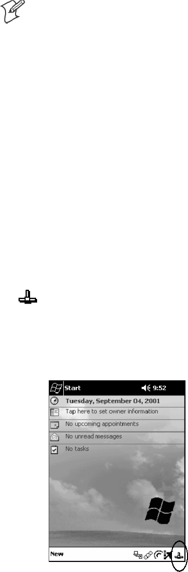
Autostart FTP
This automatically starts the FTP Server (FTPDCE.EXE) when the 700
Series Computer is powered on. This is provided with the NDISTRAY
program, which displays the popup menu that currently allows you to load
and unload the network drivers. Tap the antenna icon in the System Tray
of the Today screen (a sample antenna icon is circled below) to get this pop-
up menu.
Programming—Chapter 7
261700 Series Color Mobile Computer User’s Manual
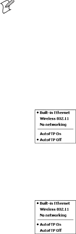
The default is to start the FTP Server at boot time, unless the following
registry entry is defined and set to “0” which disables AutoFTP. “1” enables
the AutoFTP. The entry can be set from the NDISTRAY pop-up menu by
selecting either AutoFTP On or AutoFTP Off.
HKEY_LOCAL_MACHINE\Software\Intermec\Ndistray\StartupIFTP
These new entries are located below the selections to load the network
drivers. If the StartupIFTP registry key is not defined, the FTP Server is
loaded by default, to provide “out-of-the-box” capability for customers
who want to begin loading files to the 700 Series Computer without any
prior configuration.
Note: If a network driver is unloaded using the NDISTRAY popup menu,
and the FTP Server is running, the FTP Server is stopped.
On a resume, if AutoFTP is enabled and the FTP Server is running, it is
stopped and restarted. NDISTRAY uses a helper application named RESE-
TIFTP to implement the restart on resume feature. To do an AutoFTP
Installation Check:
1Ensure the FTP Server is running “out-of-the-box” the first time.
2Tap Start →Today to access the Today screen, then tap the antenna
icon in the System Tray to bring up the NDISTRAY pop-up menu.
Select AutoFTP Off to disable AutoFTP. Do a warm boot and confirm
the FTP Server is not running.
3Tap Start →Today to access the Today screen, then tap the antenna
icon in the System Tray to bring up the NDISTRAY pop-up menu.
Select AutoFTP On to enable AutoFTP, reboot and confirm it is
running.
4Unload the network driver when the FTP Server is running and confirm
that it is not running any more.
5Load the FTP Server, establish a connection, then suspend and resume.
The server should still be running, but the FTP connection to the client
should be dropped.
ProgrammingChapter —7
262 700 Series Color Mobile Computer User’s Manual
Full Screen
Pocket PC is a hardware specification created by Microsoft Corporation.
Devices that wish to carry the Pocket PC logo must meet the minimum
hardware requirements set in the Pocket PC specification. Manufacturers
are free to add extra hardware functionality.
Pocket PC 2002 devices also use a specialized version of the CE operating
system. This OS is built from Windows CE 3.0 but contains customiza-
tions, most notably the lack of a desktop and the addition of the Today
Screen.
To carry the Pocket PC logo, all devices must be tested at an Independent
Test Laboratory. The ITL testing is done based on Microsoft requirements.
The test lab then reports the findings back to Microsoft Corporation and
Intermec Technologies. If the 700 Series Computer passed all tests, Inter-
mec is allowed to ship the device with the Pocket PC logo. Each time the
operating system is modified, Intermec must resubmit to ITL testing.
This means we cannot change the operating system much and still be a
Pocket PC device. For example, if we remove Word from the Start menu,
the device would fail ITL testing and we would not be able to ship devices
with the Pocket PC logo.
Although many customers want a Pocket PC device, some customers
would prefer that their users not have access to all of the Pocket PC featu-
res. Intermec cannot customize the operating system in any way but a cus-
tom application can:
SDelete items from the Start menu, and Programs folder. These items are
just shortcuts in the file system so the application is not really being
deleted. Cold booting the device will bring these items back so the ap-
plication will need to be run on every cold boot.
SUse the RegFlushKey() API to save a copy of the registry to a storage
device. See the Recovery CD Help for more information on how to do
this. Saving a copy of the registry will allow most system settings to be
restored in a cold boot situation.
SUse the SHFullScreen() API in conjunction with other APIs to make the
application take up the entire display and prevent the start menu from
being available.
SRemap keys and disable keys on the keypad.
SCreate a custom SIP.
SMake changes to the registry to configure the device.
Programming—Chapter 7
263700 Series Color Mobile Computer User’s Manual
Should you want your 700 Series Computer to display a full screen, keep
in mind that your computer is Pocket-PC certified by Microsoft Corpora-
tion. Check out resources on programming for the Pocket PC, using the
following links. These instructions give full instructions on how to display
full screen.
SInstructions on how to create a full screen application for eVC++ ap-
plications using an SHFullScreen() API:
http://support.microsoft.com/support/kb/articles/Q266/2/44.ASP
SInstructions on how to create a full screen application for eVB applica-
tions also using the SHFullScreen() API:
http://support.microsoft.com/support/kb/articles/Q265/4/51.ASP
ProgrammingChapter —7
264 700 Series Color Mobile Computer User’s Manual
Kernel I/O Controls
This describes the KernelIoControl() functions available to application
programmers. Most C++ applications will need to prototype the function
as the following to avoid link and compile errors.
extern “C” BOOL KernelIoControl(DWORD dwIoControlCode, LPVOID lpInBuf, DWORD
nInBufSize, LPVOID lpOutBuf, DWORD nOutBufSize, LPDWORD lpBytesReturned);
IOCTL_HAL_GET_DEVICE_INFO
This IOCTL returns either the platform type or the OEMPLATFORM
name based on an input value.
Syntax
BOOL KernelIoControl( IOCTL_HAL_GET_DEVICE_INFO, LPVOID
lpInBuf, DWORD nInBufSize, LPVOID lpOutBuf, DWORD
nOutBufSize, LPDWORD lpBytesReturned );
Parameters
lpInBuf Points to a DWORD containing either the
SPI_GETPLATFORMTYPE or SPI_GETOEMINFO
value.
lpInBufSize Must be set to sizeof(DWORD).
lpOutBuf Must point to a buffer large enough to hold the return
data of the function. If SPI_GETPLATFORMTYPE is
specified in lpInBuf, then the “PocketPC\0” Unicode
string is returned. If SPI_GETOEMINFO is specified in
lpInBuf, then the “Intermec 700\0” Unicode string is
returned.
nOutBufSize The size of lpOutBuf in bytes. Must be large enough to
hold the string returned.
lpBytesReturned The actual number of bytes returned by the function for
the data requested.
Return Values
Returns TRUE if function succeeds. Returns FALSE if the function fails.
GetLastError() may be used to get the extended error value.
Programming—Chapter 7
265700 Series Color Mobile Computer User’s Manual
IOCTL_HAL_ITC_READ_PARM
Usage
#include “oemioctl.h”
Syntax
BOOL KernelIoControl( IOCTL_HAL_ITC_READ_PARM,LPVOID
lpInBuf,DWORD nInBufSize,LPVOID lpOutBuf,DWORD
nOutBufSize,LPDWORD lpBytesReturned );
Parameters
lpInBuf Points to this structure. See “ID Field Values”below.
struct PARMS {
BYTE id;
BYTE ClassId;
};
nInBufSize Must be set to the size of the PARMS structure.
lpOutBuf Must point to a buffer large enough to hold the return
data of the function. If this field is set to NULL and
nOutBufSize is set to zero when the function is called the
function will return the number bytes required by the
buffer.
nOutBufSize The size of lpOutBuf in bytes.
lpBytesReturned The number of bytes returned by the function for the
data requested.
Return Values
Returns TRUE if function succeeds. Returns FALSE if the function fails.
GetLastError() may be used to get the error value. Either
ERROR_INVALID_PARAMETER or
ERROR_INSUFFICIENT_BUFFER may be returned when this function
is used to get the error.
ID Field Values
The id field of the PARMS structure may be one of the following values:
SITC_NVPARM_ETHERNET_ID
This IOCTL returns the Ethernet 802.11 MAC Address. Six bytes are
returned in the buffer pointed to by the lpOutBuffer parameter.
SITC_NVPARM_SERIAL_NUM
This IOCTL returns the serial number of the device in BCD format.
Six bytes are returned in the buffer pointed to by the lpOutBuffer pa-
rameter.
SITC_NVPARM_MANF_DATE
This IOCTL returns the device date of manufacture in the
BCD YYYY/MM/DD format. Four bytes are returned in the buffer
pointed to by the lpOutBuffer parameter.
ProgrammingChapter —7
266 700 Series Color Mobile Computer User’s Manual
SITC_NVPARM_SERVICE_DATE
This IOCTL returns the device’ s date of last service in BCD YYYY/
MM/DD format. Four bytes are returned in the buffer pointed to by
the lpOutBuffer parameter.
SITC_NVPARM_DISPLAY_TYPE
This IOCTL returns the device’ s display type. One byte is returned in
the buffer pointed to by the lpOutBuffer parameter.
SITC_NVPARM_EDG_IP
This IOCTL returns the device Ethernet debug IP address. Four bytes
are returned in the buffer pointed to by the lpOutBuffer parameter.
SITC_NVPARM_EDBG_SUBNET
This IOCTL returns the device Ethernet debug subnet mask. Four by-
tes are returned in the buffer pointed to by the lpOutBuffer parameter.
SITC_NVPARM_ECN
This IOCTL returns ECNs applied to the device in a bit array format.
Four bytes are returned in the buffer pointed to by the lpOutBuffer pa-
rameter.
SITC_NVPARM_CONTRAST
This IOCTL returns the device default contrast setting. Two bytes are
returned in the buffer pointed to by the lpOutBuffer parameter.
SITC_NVPARM_MCODE
This IOCTL returns the manufacturing configuration code for the de-
vice. Sixteen bytes are returned in the buffer pointed to by the lpOut-
Buffer parameter.
SITC_NVPARM_VERSION_NUMBER
This IOCTL returns the firmware version for various system compo-
nents. These values for the ClassId field of the PARMS structure are al-
lowed when ITC_NVPARM_VERSION_NUMBER is used in the id
field:
SVN_CLASS_KBD
Returns a five-byte string, including null terminator, that contains an
ASCII value which represents the keyboard microprocessor version in
the system. The format of the string is x.xx with a terminating null
character.
SVN_CLASS_ASIC
Returns a five-byte string, including null terminator, that contains an
ASCII value which represents the version of the FPGA firmware in
the system. The format of the string is x.xx with a terminating null
character.
SVN_CLASS_BOOTSTRAP
Returns a five-byte string, including null terminator, that contains an
ASCII value which represents the version of the Bootstrap Loader
firmware in the system. The format of the string is x.xx with a termi-
nating null character.
Programming—Chapter 7
267700 Series Color Mobile Computer User’s Manual
SITC_NVPARM_INTERMEC_SOFTWARE_CONTENT
This IOCTL reads the manufacturing flag bits from the non-volatile
data store that dictates certain software parameters. A BOOLEAN
DWORD is returned in the buffer pointed to by lpOutBuffer that indi-
cates if Intermec Content is enabled in the XIP regions. TRUE indicates
that it is enabled. FALSE indicates that it is not enabled.
SITC_NVPARM_ANTENNA_DIVERSITY
This IOCTL reads the state of the antenna diversity flag. A BOOLEAN
DWORD is returned in the buffer pointed to by lpOutBuffer that indi-
cates if there is a diversity antenna installed. TRUE indicates that it is
installed. FALSE indicates that it is not installed.
SITC_NVPARM_WAN_RI
This IOCTL reads the state of the WAN ring indicator flag. A BOOL-
EAN DWORD is returned in the buffer pointed to by lpOutBuffer that
indicates the polarity of the WAN RI signal. TRUE indicates active
high. FALSE indicates active low.
SITC_NVPARM_RTC_RESTORE
This IOCTL reads the state of the real-time clock restore flag. A
BOOLEAN DWORD is returned in the buffer pointed to by lpOutBuf-
fer. TRUE indicates that the RTC will be restored upon a cold boot.
FALSE indicates that the RTC will not be restored.
SITC_NVPARM_INTERMEC_DATACOLLECTION_SW
This IOCTL reads the state of the data collection software enabled flag.
A BOOLEAN DWORD is returned in the buffer pointer to by lpOut-
Buffer that indicates the data collection software is to be installed at boot
time. FALSE indicates the data collection software should not be
installed.
SITC_NVPARM_INTERMEC_DATACOLLECTION_HW
This IOCTL reads the data collection hardware flags. A BYTE is re-
turned in the buffer pointer to by lpOutBuffer that indicates the type of
data collection hardware installed. The maximum possible value re-
turned is ITC_DEVID_SCANHW_MAX.
SITC_DEVID_SCANHW_NONE
No scanner hardware is installed.
SITC_DEVID_OEM2D_IMAGER
OEM 2D imager is installed.
SITC_DEVID_INTERMEC2D_IMAGER
Intermec 2D imager is installed.
SITC_DEVID_SE900_LASER
SE900 laser is installed.
SITC_DEVID_SE900HS_LASER
SE900HS laser is installed.
The high bit indicates whether the S6 scanning engine is installed. The
bit mask for this is ITC_DEVID_S6ENGINE_MASK. A non-zero val-
ue indicates that the S6 scanning engine is installed.
ProgrammingChapter —7
268 700 Series Color Mobile Computer User’s Manual
SITC_NVPARM_WAN_INSTALLED
This IOCTL reads the state of the WAN radio installed flag. A BOOL-
EAN DWORD is returned in the buffer pointed to by lpOutBuffer.
TRUE indicates that the WAN radio is installed. FALSE indicates that
no WAN radio is installed.
SITC_NVPARM_WAN_FREQUENCY
This IOCTL reads the state of the WAN radio frequency flag. A
BOOLEAN DWORD is returned in the buffer pointed to by lpOutBuf-
fer. TRUE indicates that the WAN radio frequency is United States.
FALSE indicates that the WAN radio frequency is European.
SITC_NVPARM_WAN_RADIOTYPE
This IOCTL reads the WAN radio ID installed by manufacturing. A
BYTE is returned in the buffer pointer to by lpOutBuffer which indi-
cates the type of WAN radio hardware installed. The maximum possible
value returned is ITC_DEVID_WANRADIO_MAX. The current defi-
nitions are:
SITC_DEVID_WANRADIO_NONE
No WAN radio installed.
SITC_DEVID_WANRADIO_SIERRA_SB555
CDMA Sierra Wireless radio.
SITC_DEVID_WANRADIO_XIRCOM_GEM3503
GSM/GPRS Intel (Xircom) radio.
SITC_DEVID_WANRADIO_SIEMENS_MC45
GSM/GPRS Siemens radio.
SITC_NVPARM_80211_INSTALLED
This IOCTL reads the state of the 802.11b radio installed flag. A
BOOLEAN DWORD is returned in the buffer pointed to by lpOutBuf-
fer. TRUE indicates that the 802.11b radio is installed. FALSE indicates
that no 802.11b radio is installed.
SITC_NVPARM_80211_RADIOTYPE
This IOCTL reads the 802.11b radio ID installed by manufacturing. A
BYTE is returned in the buffer pointer to by lpOutBuffer that indicates
the type of 802.11b radio hardware installed. The maximum possible
value returned is ITC_DEVID_80211RADIO_MAX. The current defi-
nitions are:
SITC_DEVID_80211RADIO_NONE
No 802.11b radio installed.
SITC_DEVID_80211RADIO_INTEL_2011B
Intel 2011B radio installed.
SITC_NVPARM_BLUETOOTH_INSTALLED
This IOCTL reads the state of the Bluetooth radio installed flag. A
BOOLEAN DWORD is returned in the buffer pointed to by lpOutBuf-
fer. TRUE indicates that the Bluetooth radio is installed. FALSE indi-
cates that no Bluetooth radio is installed.
Programming—Chapter 7
269700 Series Color Mobile Computer User’s Manual
SITC_NVPARM_SERIAL2_INSTALLED
This IOCTL reads the state of the serial 2 (COM2) device installed
flag. A BOOLEAN DWORD is returned in the buffer pointed to by
lpOutBuffer. TRUE indicates that the serial 2 device is installed. FALSE
indicates that no serial 2 device is installed.
SITC_NVPARM_VIBRATE_INSTALLED
This IOCTL reads the state of the vibrate device installed flag. A
BOOLEAN DWORD is returned in the buffer pointed to by lpOutBuf-
fer. TRUE indicates that the vibrate device is installed. FALSE indicates
that no vibrate device is installed.
SITC_NVPARM_LAN9000_INSTALLED
This IOCTL reads the state of the Ethernet device installed flag. A
BOOLEAN DWORD is returned in the buffer pointed to by lpOutBuf-
fer. TRUE indicates that the Ethernet device is installed. FALSE indi-
cates that no Ethernet device is installed.
SITC_NVPARM_SIM_PROTECT_HW_INSTALLED
This IOCTL reads the state of the SIM card protection hardware
installed flag. A BOOLEAN DWORD is returned in the buffer pointed
to by lpOutBuffer. TRUE indicates that the SIM card protection hard-
ware is installed. FALSE indicates that no SIM card protection hardware
is installed.
SITC_NVPARM_SIM_PROTECT_SW_INSTALLED
This IOCTL reads the state of the SIM card protection software
installed flag. A BOOLEAN DWORD is returned in the buffer pointed
to by lpOutBuffer. TRUE indicates that the SIM card protection soft-
ware is installed. FALSE indicates that no SIM card protection software
is installed.
ProgrammingChapter —7
270 700 Series Color Mobile Computer User’s Manual
IOCTL_HAL_ITC_WRITE_SYSPARM
Describes and enables the registry save location.
Usage
#include “oemioctl.h”
Syntax
BOOL KernelIoControl( IOCTL_HAL_ITC_WRITE_SYSPARM,LPVOID
lpInBuf,DWORD nInBufSize, LPVOID lpOutBuf, DWORD
nOutBufSize, LPDWORD lpBytesReturned );
Parameters
lpInBuf A single byte that may be one of the id values.
See “ID Field Values”below.
nInBufSize Must be set to the size of the lpInBuf in bytes.
lpOutBuf Must point to a buffer large enough to hold the data to
be written to the non-volatile data store.
nOutBufSize The size of lpOutBuf in bytes.
lpBytesReturned The number of bytes returned by the function.
Return Values
Returns TRUE if function succeeds. Returns FALSE if the function fails.
GetLastError() may be used to get the error value. Either
ERROR_INVALID_PARAMETER or
ERROR_INSUFFICIENT_BUFFER may be returned when this function
is used to get the error.
ID Field Values
The id field of lpInBuf may be one of the following values:
SITC_REGISTRY_LOCATION
This IOCTL sets the default location for where to write the registry
when RegFlushKey() is called by an application. The registry may be
saved to Flash, a CompactFlash storage card or a SecureDigital storage
card. lpOutBuf must point to a buffer that contains a byte value of “1”
for the CompactFlash card or “2” for the SecureDigital card to specify
the location.
SITC_REGISTRY_SAVE_ENABLE
This function enables or disables the save registry to non-volatile media
feature of the RegFlushKey() function. lpOutBuf must be set to zero
(FALSE) if the feature is to be disabled or one (TRUE) if the feature is
to be enabled.
SITC_ DOCK_SWITCH
This IOCTL sets a position of the dock switch. The dock switch may
be set to either “modem” or “serial” positions. lpOutBuf must point to a
buffer that contains a byte value of either DOCK_MODEM or
DOCK_SERIAL as defined in OEMIOCTL.H; the value specifies the
position the switch is to be set.
Programming—Chapter 7
271700 Series Color Mobile Computer User’s Manual
SITC_ WAKEUP_MASK
This IOCTL sets a bit mask that represents the mask for the five pro-
grammable wakeup keys. The I/O key is not a programmable wakeup
key. By default it is always the system resume key and all other keys are
set to disable key wakeup. A zero in a bit position masks the wakeup for
that key. A one in a bit position enables wakeup for that key. lpOutBuf
must point to a buffer that contains a byte value of a wakeup mask con-
sisting of the OR’ ed constants as defined in OEMIOCTL.H. Only the
following keys are programmable as wakeup events.
#define SCANNER_TRIGGER 1
#define SCANNER_LEFT 2
#define SCANNER_RIGHT 4
#define GOLD_A1 8
#define GOLD_A2 0x10
SITC_AMBIENT_KEYBOARD
This IOCTL sets the threshold for the keyboard ambient sensor. This
can be a value from 0 (always off ) to 255 (always on). lpOutBuf must
point to a buffer that contains a byte value of the desired setting.
SITC_AMBIENT_FRONTLIGHT
This IOCTL sets the threshold for the frontlight ambient sensor. This
can be a value from 0 (always off ) to 255. lpOutBuf must point to a
buffer that contains a byte value of the desired setting.
ProgrammingChapter —7
272 700 Series Color Mobile Computer User’s Manual
IOCTL_HAL_GET_DEVICEID
This IOCTL returns the device ID. There are two types of device IDs sup-
ported, which are differentiated based on the size of the output buffer. The
UUID is returned if the buffer size is set to sizeof(UNIQUE_DEVICEID),
otherwise the oldstyle device ID is returned.
Usage
#include “pkfuncs.h”
#include “deviceid.h”
Syntax
BOOL KernelIoControl( IOCTL_HAL_GET_DEVICEID,LPVOID
lpInBuf,DWORD nInBufSize,LPVOID lpOutBuf,DWORD
nOutBufSize,LPDWORD lpBytesReturned );
Parameters
lpInBuf Should be set to NULL. STRICT_ID settings are not
supported.
lpInBufSize Should be set to zero.
lpOutBuf Must point to a UNIQUE_DEVICEID structure as
defined by DEVICEID.H if the UUID is to be returned.
nOutBufSize The size of the UNIQUE_DEVICEID in bytes if the
UUID is to be returned. A DEVICE_ID as defined by
PKFUNCS.H is returned if the size in bytes is greater
than or equal to sizeof(DEVICE_ID).
lpBytesReturned The number of bytes returned by the function.
Return Values
Returns TRUE if function succeeds. Returns FALSE if the function fails.
GetLastError() may be used to get the extended error value.
Programming—Chapter 7
273700 Series Color Mobile Computer User’s Manual
IOCTL_HAL_GET_OAL_VERINFO
Returns the HAL version information of the Pocket PC image.
Usage
#include “oemioctl.h”
Syntax
BOOL KernelIoControl( IOCTL_HAL_GET_OAL_VERINFO,LPVOID
lpInBuf,DWORD nInBufSize,LPVOID lpOutBuf,DWORD
nOutBufSize,LPDWORD lpBytesReturned );
Parameters
lpInBuf Should be set to NULL.
lpInBufSize Should be set to zero.
lpOutBuf Must point to a VERSIONINFO structure as defined by
OEMIOCTL.H. The fields should have these values:
Scboemverinfo sizeof (tagOemVerInfo);
Sverinfover 1
Ssig; “ITC\0”
Sid; ‘N’
Stgtcustomer “”
Stgtplat SeaRay
Stgtplatversion Current build version number
Stgtcputype[8]; “Intel\0”
Stgtcpu “PXA250\0”;
Stgtcoreversion “”
Sdate Build time
Stime Build date
nOutBufSize The size of VERSIONINFO in bytes.
lpBytesReturned Returns sizeof(PVERSIONINFO).
Return Values
Returns TRUE if function succeeds. Returns FALSE if the function fails.
GetLastError() may be used to get the extended error value.
ProgrammingChapter —7
274 700 Series Color Mobile Computer User’s Manual
IOCTL_HAL_GET_BOOTLOADER_VERINFO
Returns the HAL version information of the Pocket PC image.
Usage
#include “oemioctl.h”
Syntax
BOOL KernelIoControl( IOCTL_HAL_GET_OAL_VERINFO,LPVOID
lpInBuf, DWORD nInBufSize,LPVOID lpOutBuf,DWORD
nOutBufSize,LPDWORD lpBytesReturned );
Parameters
lpInBuf Should be set to NULL.
lpInBufSize Should be set to zero.
lpOutBuf Must point to a VERSIONINFO structure as defined by
OEMIOCTL.H. The fields should have these values:
Scboemverinfo Sizeof (tagOemVerInfo);
Sverinfover 1
Ssig; “ITC\0”
Sid; ‘B’
Stgtcustomer “”
Stgtplat SeaRay
Stgtplatversion Current build version number of
the bootstrap loader
Stgtcputype[8]; “Intel\0”;
Stgtcpu “PXA250\0”
Stgtcoreversion “”
Sdate Build time
Stime Build date
nOutBufSize The size of VERSIONINFO in bytes.
lpBytesReturned The number of bytes returned to lpOutBuf.
Return Values
Returns TRUE if function succeeds. Returns FALSE if the function fails.
GetLastError() may be used to get the extended error value.
Programming—Chapter 7
275700 Series Color Mobile Computer User’s Manual
IOCTL_HAL_WARMBOOT
Causes the system to perform a warm-boot. The object store is retained.
Usage
#include “oemioctl.h”
Syntax
BOOL KernelIoControl( IOCTL_HAL_WARMBOOT,LPVOID
lpInBuf,DWORD nInBufSize,LPVOID lpOutBuf,DWORD
nOutBufSize,LPDWORD lpBytesReturned );
Parameters
lpInBuf Should be set to NULL.
lpInBufSize Should be set to zero.
lpOutBuf Should be NULL.
nOutBufSize Should be zero.
Return Values
None.
IOCTL_HAL_COLDBOOT
Causes the system to perform a cold-boot. The object store is cleared.
Usage
#include “oemioctl.h”
Syntax
BOOL KernelIoControl( IOCTL_HAL_COLDBOOT,LPVOID
lpInBuf,DWORD nInBufSize,LPVOID lpOutBuf,DWORD
nOutBufSize,LPDWORD lpBytesReturned );
Parameters
lpInBuf Should be set to NULL.
lpInBufSize Should be set to zero.
lpOutBuf Should be NULL.
nOutBufSize Should be zero.
Return Values
None.
ProgrammingChapter —7
276 700 Series Color Mobile Computer User’s Manual
IOCTL_HAL_GET_RESET_INFO
This IOCTL code allows software to check the type of the most recent re-
set.
Usage
#include “oemioctl.h”
Syntax
BOOL KernelIoControl( IOCTL_HAL_GET_RESET_INFO,LPVOID
lpInBuf,DWORD nInBufSize,LPVOID lpOutBuf,DWORD
nOutBufSize,LPDWORD lpBytesReturned );
Parameters
lpInBuf Should be set to NULL.
lpInBufSize Should be set to zero.
lpOutBuf Must point to a HAL_RESET_INFO structure:
typedef struct {
DWORD ResetReason; // most recent reset type
DWORD ObjectStoreState; // state of object store
} HAL_RESET_INFO, * PHAL_RESET_INFO;
// Reset reason types
#define HAL_RESET_TYPE_UNKNOWN 0
#define HAL_RESET_REASON_HARDWARE 1 // cold
#define HAL_RESET_REASON_SOFTWARE 2 // suspend
#define HAL_RESET_REASON_WATCHDOG 4
#define HAL_RESET_BATT_FAULT 8 // power fail
#define HAL_RESET_VDD_FAULT 16 // warm boot
// Object store state flags
#define HAL_OBJECT_STORE_STATE_UNKNOWN 0
#define HAL_OBJECT_STORE_STATE_CLEAR 1
nOutBufSize The size of HAL_RESET_INFO in bytes.
lpBytesReturned The number of bytes returned by the function.
Return Values
Returns TRUE if function succeeds. Returns FALSE if the function fails.
GetLastError() may be used to get the extended error value.
Programming—Chapter 7
277700 Series Color Mobile Computer User’s Manual
IOCTL_HAL_GET_BOOT_DEVICE
This IOCTL code allows software to check which device CE booted from.
Usage
#include “oemioctl.h”
Syntax
BOOL KernelIoControl( IOCTL_HAL_GET_BOOT_DEVICE,LPVOID
lpInBuf,DWORD nInBufSize,LPVOID lpOutBuf,DWORD
nOutBufSize,LPDWORD lpBytesReturned );
Parameters
lpInBuf Should be set to NULL.
lpInBufSize Should be set to zero.
lpOutBuf Must point to a buffer large enough to hold a DWORD
(4 bytes) that contains the boot device. The following
boot devices are supported:
#define HAL_BOOT_DEVICE_UNKNOWN 0
#define HAL_BOOT_DEVICE_ROM_XIP 1
#define HAL_BOOT_DEVICE_ROM 2
#define HAL_BOOT_DEVICE_PCMCIA_ATA 3
#define HAL_BOOT_DEVICE_PCMCIA_LINEAR 4
#define HAL_BOOT_DEVICE_IDE_ATA 5
#define HAL_BOOT_DEVICE_IDE_ATAPI 6
nOutBufSize The size of lpOutBuf in bytes (4).
lpBytesReturned The number of bytes returned by the function.
Return Values
Returns TRUE if function succeeds. Returns FALSE if the function fails.
GetLastError() may be used to get the extended error value.
ProgrammingChapter —7
278 700 Series Color Mobile Computer User’s Manual
IOCTL_HAL_REBOOT
Causes the system to perform a warm-boot. The object store is retained.
Usage
#include “oemioctl.h”
Syntax
BOOL KernelIoControl( IOCTL_HAL_REBOOT,LPVOID lpInBuf,DWORD
nInBufSize,LPVOID lpOutBuf,DWORD nOutBufSize,LPDWORD
lpBytesReturned );
Parameters
lpInBuf Should be set to NULL.
lpInBufSize Should be set to zero.
lpOutBuf Should be NULL.
nOutBufSize Should be zero.
Return Values
None.
Programming—Chapter 7
279700 Series Color Mobile Computer User’s Manual
IOCTL_PROCESSOR_INFORMATION
Returns processor information.
Usage
#include “pkfuncs.h”
Syntax
BOOL KernelIoControl( IOCTL_PROCESSOR_INFORMATION,LPVOID
lpInBuf,DWORD nInBufSize,LPVOID lpOutBuf,DWORD
nOutBufSize,LPDWORD lpBytesReturned );
Parameters
Parameters:
lpInBuf Should be set to NULL.
lpInBufSize Should be set to zero.
lpOutBuf Should be a pointer to the PROCESSOR_INFO
structure. The PROCESSOR_INFO structure stores
information that describes the CPU more descriptively.
typedef __PROCESSOR_INFO {
WORD wVersion; // Set to value 1
WCHAR szProcessorCore[40]; // “ARM\0”
WORD wCoreRevision; // 4
WCHAR szProcessorName[40]; // “PXA250\0”
WORD wProcessorRevision; // 0
WCAHR szCatalogNumber[100]; // 0
WCHAR szVendor[100]; // “Intel Corporation\0”
DWORD dwInstructionSet; // 0
DWORD dwClockSpeed; // 400
}
nOutBufSize Should be set to sizeof(PROCESSOR_INFO) in bytes.
lpBytesReturned Returns sizeof(PROCESSOR_INFO);
Return Values
Returns TRUE if function succeeds. Returns FALSE if the function fails.
GetLastError() may be used to get the extended error value.
ProgrammingChapter —7
280 700 Series Color Mobile Computer User’s Manual
IOCTL_GET_CPU_ID
Returns Xscale processor ID.
Usage
#include “oemioctl.h”
Syntax
BOOL KernelIoControl( IOCTL_GET_CPU_ID,LPVOID lpInBuf, DWORD
nInBufSize,LPVOID lpOutBuf,DWORD nOutBufSize,LPDWORD
lpBytesReturned );
Parameters
lpInBuf Should point to a CPUIdInfo structure defined in
OEMIOCTL.H.
lpInBufSize Should be sizeof(CPUIdInfo).
lpOutBuf Should be NULL.
nOutBufSize Should be set to 0.
lpBytesReturned Returns sizeof(PROCESSOR_INFO);
Return Values
Returns TRUE if function succeeds. Returns FALSE if the function fails.
GetLastError() may be used to get the extended error value.
Reboot Functions
There are several methods, via Kernel I/O Control functions, that an ap-
plication program can use to force the 700 Series Computer to reboot.
IOCTL_HAL_REBOOT
IOCTL_HAL_REBOOT performs a warm-boot. See page 278.
IOCTL_HAL_COLDBOOT
Invoking the KernelIOControl function with
IOCTL_HAL_COLDBOOT forces a cold reboot. This resets the 700
Series Computer and reloads Windows CE as if a power-up had been
performed. The contents of the Windows CE RAM-based object store are
discarded. See page 275.
IOCTL_HAL_WARMBOOT
This function is supported on the 700 Series Computers. It performs a
warm boot of the system, preserving the object store. See page 275.

Programming—Chapter 7
281700 Series Color Mobile Computer User’s Manual
Remapping the Keypad
Note; Use caution when remapping the keypad. Improper remapping may
render the keypad unusable. Data within the 700 Series Computer could
also be lost, should any problems occur.
Applications have the ability to remap keys on the 700 Color Keypad. This
will allow applications to enable keys that would otherwise not be availa-
ble, such as the [F1] function key. Also, to disable keys that should not be
available, such as the alpha key because no alpha entry is required. Care
should be exercised when attempting to remap the keypad because im-
proper remapping may cause the keypad to become unusable. This can be
corrected by cold booting the device which will cause the default keymap
to be loaded again.
Note that remapping the keys in this way affects the key mapping for the
entire system, not just for the application that does the remapping.
There are three “planes” supported for the 740 Keypad. Keys that are to be
used in more than one shift plane must be described in each plane.
Unshifted Plane
The unshifted plane contains values from the keypad when not pressed
with other keys, such as the following:
S[1] 1
S[5] 5
S[9] 9
Gold Plane
The gold plane contains values from the keypad when a key is simulta-
neously pressed with the [Gold] key, such as the following:
S[Gold] +[1] Send
S[Gold] +[5] A3
S[Gold] +[9] PageDown
Alpha Plane
The alpha plane contains values from the keypad when the keypad has
been placed in alpha mode by pressing the blue alpha key, such as the fol-
lowing:
S[Alpha] +[1] Caps
S[Alpha] +[5] JKL
S[Alpha] +[9] WXYZ

ProgrammingChapter —7
282 700 Series Color Mobile Computer User’s Manual
Key Values
Key values for each plane are stored in the registry. All units ship with a
default key mapping already loaded in the registry. Applications that wish
to change the default mapping need to read the appropriate key from the
registry into an array of Words, modify the values required and then write
the updated values back into the registry. The registry access can be done
with standard Microsoft API calls, such as RegOpenKeyEx(), RegQuery-
ValueEx(), and RegSetValueEx().
SThe unshifted plane mapping can be found in the registry at:
HKEY_LOCAL_MACHINE\HARDWARE\DEVICEMAP\KEYBD\Vkey
SThe gold plane mapping can be found in the registry at:
HKEY_LOCAL_MACHINE\HARDWARE\DEVICEMAP\KEYBD\VkeyGold
SThe alpha plane mapping can be found in the registry at:
HKEY_LOCAL_MACHINE\HARDWARE\DEVICEMAP\KEYBD\VkeyAlpha
How Key Values Are Stored in Registry
To know which fields to update in the registry, you must know what Scan
Codes are assigned to each physical key (see the table below). The Scan
Code is used at the lowest level of the system to let the keypad driver know
which physical key has been pressed. The keypad driver takes that scan
code and looks it up in a table (a copy of the one stored in the registry) to
determine which values to pass on to the operating system.
Each registry key is just an array that describes to the keypad driver what
value needs to be passed for each physical key. The key values are indexed
by the scan code, this is a zero-based index. For example in the unshifted
plane, the [4] key has a scan code of 0x06. This means that the seventh
word under the “Vkey” registry key will have the value for the [4] key.
Taking a sample of the “Vkey” registry key shows the following values:
00,00,0B,05,02,03,C1,07,04,03,BE,00,34,00,00,00,. . .
The value is 34,00. The values are in reverse byte order because that is the
way the processor handles data. When writing an application, nothing
needs to be done to swap the bytes, as this will happen automatically when
the data is read into a byte value. This is something you just need to be
aware of this when looking at the registry. Knowing this, we can see that
the value that the keypad driver will pass to the system is a hex 34. Look-
ing that up on an UNICODE character chart, we see that it maps to a “4”.
If you wanted the key, labeled “4”, to output the letter “A” instead, you
would need to change the seventh word to “41” (the hexadecimal represen-
tation of “A” from the UNICODE chart), then put the key back into the
registry.
Note: Do not remap scan codes 0x01, 0x41, 0x42, 0x43, 0x44. Remap-
ping these scan codes could render your 700 Series Computer unusable
until a cold-boot is performed.
If you wish to disable a certain key, remap its scan code to 0x00.

Programming—Chapter 7
283700 Series Color Mobile Computer User’s Manual
Change Notification
Just changing the registry keys will not immediately change the key
mappings. To notify the keypad driver that the registry has been updated,
signal the “ITC_KEYBOARD_CHANGE” named event using the
CreateEvent() API.
Advanced Keypad Remapping
It is also possible to map multiple key presses to one button and to map
named system events to a button. The multiple key press option could be
useful to cut down on the number of keys needed to press in a given situa-
tion or to remap which key behaves like the action key. Mapping events to
a button could be useful to change which buttons will fire the scanner,
control volume, and allow for suspending and resuming the device. If you
need help performing one of these advanced topics please contact Intermec
Technical Support.
Scan Codes
At the lowest driver level, the 740 Keypad identifies keys as scan codes.
These scan codes are sent via the keypad microcontroller, and cannot be
changed without modifying the keypad firmware.
Key/Meaning Scancode
Reserved 0x00
I/O Button 0x01
Scanner Trigger 0x02
Scanner Left 0x03
Scanner Right 0x04
.0x05
40x06
None 0x07
Left Arrow 0x08
None 0x09
Backspace 0x0A
Gold Key 0x0B
None 0x0C
ESC 0x0D
Down Arrow 0x0E
10x0F
70x10
Alpha Key 0x11
None 0x12
Up Arrow 0x13
Right Arrow 0x14
20x15
80x16
00x17
50x18
None 0x19

ProgrammingChapter —7
284 700 Series Color Mobile Computer User’s Manual
Key/Meaning Scancode
Action Key 0x1A
30x1B
90x1C
ENTER 0x1D
60x1E
None 0x1F-0x40
Charge Detect 0x41
LCD Frontlight 0x42
Ambient Light 0x42
Threshold Crossed 0x42
Headset Detected 0x43
Keypad Backlight 0x44
Ambient Light 0x44
Threshold Crossed 0x44
Sample View of Registry Keys
The following is a sample view of the current default key mapping. See the
registry on your device for the latest key mappings.
[HKEY_LOCAL_MACHINE\HARDWARE\DEVICEMAP\KEYBD]
”ResumeMask”=dword:7
”Vkey”=hex: 00,00,0B,05,02,03,C1,07,04,03,BE,00,34,00,00,00,\
25,00,00,00,08,00,03,02,00,00,1B,00,28,00,31,00,\
37,00,01,02,00,00,26,00,27,00,32,00,38,00,30,00,\
35,00,00,00,01,03,33,00,39,00,0D,00,36,00,00,00,\
00,00,00,00,00,00,00,00,00,00,00,00,00,00,00,00,\
00,00,00,00,00,00,00,00,00,00,00,00,00,00,00,00,\
00,00,00,00,00,00,00,00,00,00,00,00,00,00,00,00,\
00,00,00,00,00,00,00,00,00,00,00,00,00,00,00,00,\
00,00,07,05,01,05,03,05,02,05
”VkeyGold”=hex: 00,00,0B,05,02,03,C1,07,04,03,BE,00,34,00,00,00,\
09,01,00,00,BF,00,03,02,00,00,BD,00,75,00,72,00,\
21,00,01,02,00,00,76,00,09,00,73,00,38,01,5B,00,\
35,00,00,00,BB,01,09,05,22,00,32,01,36,00,00,00,\
00,00,00,00,00,00,00,00,00,00,00,00,00,00,00,00,\
00,00,00,00,00,00,00,00,00,00,00,00,00,00,00,00,\
00,00,00,00,00,00,00,00,00,00,00,00,00,00,00,00,\
00,00,00,00,00,00,00,00,00,00,00,00,00,00,00,00,\
00,00,07,05,01,05,03,05,02,05
”VkeyAlpha”=hex: 00,00,0B,05,02,03,C1,07,04,03,BE,00,47,00,00,00,\
25,00,00,00,08,00,03,02,00,00,1B,00,28,00,02,02,\
50,00,01,02,00,00,26,00,27,00,41,00,54,00,20,00,\
4A,00,00,00,01,03,44,00,57,00,0D,00,4D,00,00,00,\
00,00,00,00,00,00,00,00,00,00,00,00,00,00,00,00,\
00,00,00,00,00,00,00,00,00,00,00,00,00,00,00,00,\
00,00,00,00,00,00,00,00,00,00,00,00,00,00,00,00,\
00,00,00,00,00,00,00,00,00,00,00,00,00,00,00,00,\
00,00,07,05,01,05,03,05,02,05

285700 Series Color Mobile Computer User’s Manual
Control Panel Applets
A
This appendix contains information about the Data Collection, SNMP,
and User Information Control Panel applets that may be on your 700 Se-
ries Color Mobile Computer.
SNMP and Data Collection settings that can appear under Settings are
dependent on what hardware configuration is done for each 700 Series
Computer at the time of shipment. These settings will currently only ap-
pear if a scanner or an imager option is present.
Likewise, other control panel applets that are specifically related to the
802.11b radio module will appear when a 802.11b radio module is
installed in a 700 Series Computer. Control panel applets that are specific
for Wireless Printing, CDMA/1xRTT, and GSM/GPRS radio modules
will only appear when each respective hardware configuration is done on
the 700 Series Computer. See Chapter 4, “Network Support,” for more infor-
mation about the radio modules or the wireless printing.
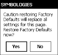
Control Panel AppletsAppendix —A
286 700 Series Color Mobile Computer User’s Manual
Configuration Parameters
A configuration parameter changes the way the 700 Series Color (700C)
Mobile Computer operates, such as configuring a parameter to have the
700 Series Computer emit a very loud beep in a noisy environment. Use
any of the following methods to execute configuration parameters:
SChange Data Collection and SNMP parameters via control panel ap-
plets later in this appendix.
SAccess the 700 Series Computer via the Unit Manager through a web
browser on your desktop PC via the SRDEVMGMT.CAB file. To use
the Unit Manager, install this CAB file from the 700 Color Software
Tools CD-ROM. Unit Manager applications are available on the 700
Series Color Unit Manager CD-ROM. For more information, consult
your Intermec sales representative.
SSend parameters from an SNMP management station. See “SNMP Con-
figuration” starting on page 123.
SScan EasySet bar codes. You can use the EasySet bar code creation soft-
ware from Intermec Technologies Corporation to print configuration
labels. Scan the labels to change the scanner configuration and data
transfer settings.
Changing a Parameter Setting
Menus of available parameters for each group are listed. Use the scroll bars
to go through the list. Expand each menu (+) to view its parameter set-
tings. Tap a parameter to select, or expand a parameter (+) to view its sub-
parameters.
Note that each parameter or subparameter is shown with its default setting
or current setting in (< >) brackets. Tap a parameter or subparameter to
select that parameter, then do any of the following to change its setting:
Tap Apply to apply any changes. Note that these illustrations are from a
Symbologies parameter.
STyping a new value in an entry field.
SChoosing a new value from the drop-down list.
SSelecting a different option. The selected option contains a bullet.
STap Defaults, then Apply to restore factory-default settings. Tap Yes
when you are prompted to verify this action.
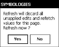
Control Panel AppletsAppendix —A
287700 Series Color Mobile Computer User’s Manual
STap Refresh to discard changes and start again. Tap Yes when you are
prompted to verify this action.
About Configuration Parameters
You can find the following information about each configuration parame-
ter:
SName and Purpose:
Describes the parameter and its function.
SAction:
Describes what to do with a parameter once that parameter is selected.
SSNMP OID:
Lists the SNMP OID for the parameter.
SSyntax or Options:
Syntax lists the two-character code for the parameter, if the parameter is
configurable by scanning a bar code or by sending parameters through a
network. Both Syntax and Options list acceptable values for the para-
meter. Default settings are noted in italic.
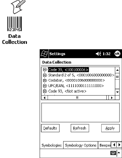
Control Panel AppletsAppendix —A
288 700 Series Color Mobile Computer User’s Manual
Data Collection Control Panel Applet
See “Scanner Control and Data Transfer”intheIntermec Windows CE/Pocket
PC Software Developer’ s Kit (SDK) User’ s Manual shipped with the Soft-
ware Developer’ s Kit (SDK) for information about data collection func-
tions.
Note: Icons are shown to the left.
To access the settings from the 700 Series Computer, tap Start →Settings
→the System tab →the Data Collection icon to access its control panel
applet.
Use the left and right arrows to scroll through the tabs along the bottom of
the control panel applet, then tap a tab to access its menus. These tabs rep-
resent the following groups of settings or parameters:
SSymbologies
SSymbology Options (starting on page 309)
SBeeper/LED (starting on page 317)
SImager (starting on page 323)
SVirtual Wedge (starting on page 325)

Control Panel AppletsAppendix —A
289700 Series Color Mobile Computer User’s Manual
Symbologies
You can change bar code symbology parameter settings in your 700 Series
Computer via the Data Collection control panel applet. The following
parameters are for bar code symbologies. Additional information about the
more common bar code symbologies are in Appendix C, “Bar Code
Symbologies.” Note that these parameters are listed in the order of their
appearance within this tab.
Most of these symbologies apply to both the imager and the laser scanner
tools. However, when using an imager, the Macro PDF (page 300), Micro
PDF 417 (page 302), Matrix 2 of 5 (page 304), Telepen (page 305),and
Code 11 (page 306) symbologies are not supported. Likewise, when using
a laser scanner, the QR Code (page 307) and Data Matrix (page 308)
symbologies are not supported.
The following table shows which bar code symbologies are supported ei-
ther by an imager or by a laser scanner.
Bar Code Symbology Imager Laser Scanner
Code 39 XX
Interleaved 2 of 5 X X
Standard 2 of 5 XX
Matrix 2 of 5 X
Code 128 XX
Code 93 X X
Codabar XX
MSI X
Plessey X
UPC X X
EAN/EAN 128 XX
Code 11 X
PDF 417 XX
Micro PDF 417 X
Tel e p e n X
Data Matrix X
QR Code X
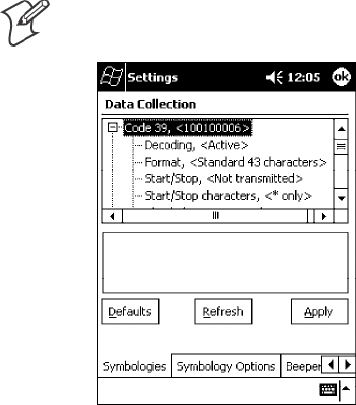
Control Panel AppletsAppendix —A
290 700 Series Color Mobile Computer User’s Manual
Code 39
Code 39 is a discrete, self-checking, variable length symbology. The char-
acter set is uppercase A-Z, 0-9, dollar sign ($), period (.), slash (/), percent
(%), space ( ), plus (+), and minus (-).
Action
Tap (+) to expand the Code 39 parameter, select the setting to be changed,
then tap an option to change this setting or select an option from the
drop-down list.
SNMP OID
1.3.6.1.4.1.1963.15.3.3.1.1.3.1
Options
Decoding 0 Not active
1 Active (default)
Format 0 Standard 43 characters (default)
1 Full ASCII
Start/Stop 0 Not transmitted (default)
1 Transmitted
Start/Stop characters (Not supported when using an imager):
0 $ (dollar sign) only
1 * (asterisk) only (default)
2 & and * (dollar sign and asterisk)
Check digit 0 Not used (default)
1 Mod 43 transmitted
2 Mod 43 not transmitted
3 French CIP transmitted
4 French CIP not transmitted
5 Italian CPI transmitted
6 Italian CPI not transmitted
Bar code length 0 Any length (default)
1 Minimum length
Minimum length 000-254 Minimum length 1-254 (6)
Note:IfBar code length =“1”thenMinimum length is entered.
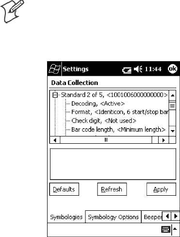
Control Panel AppletsAppendix —A
291700 Series Color Mobile Computer User’s Manual
Standard 2 of 5
Standard 2 of 5 is a discrete and self-checking symbology that uses the bars
to encode information and the spaces to separate the individual bars.
Action
Tap (+) to expand the Standard 2 of 5 parameter, select the setting to be
changed, then tap an option to change this setting or select an option from
the drop-down list.
SNMP OID
1.3.6.1.4.1.1963.15.3.3.1.1.4.1
Options
Decoding 0 Not active (default)
1 Active
Format 0 Identicon, 6 start/stop bars (default)
1 Computer Identics, 4 start/stop
Check digit 0 Not used (default)
1 Mod 10 transmitted
2 Mod 10 not transmitted
Bar code length 0 Any length
1 Minimum length (default)
2 Fixed lengths
Minimum length 001-254 Minimum length 1-254 (6)
Fixed length 1 000-254 Fixed bar code length 0-254 (0)
Fixed length 2 000-254 Fixed bar code length 0-254 (0)
Fixed length 3 000-254 Fixed bar code length 0-254 (0)
Note:IfBar code length =“1”thenMinimum length is entered. If Bar
code length =“2”thenFixed length 1,Fixed length 2,orFixed length 3
is entered.
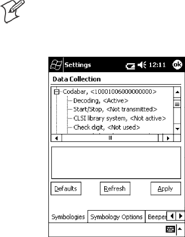
Control Panel AppletsAppendix —A
292 700 Series Color Mobile Computer User’s Manual
Codabar
Codabar is a self-checking, discrete symbology.
Action
Tap (+) to expand the Codabar parameter, select a setting to be changed,
then select an option from the drop-down list to change this setting.
SNMP OID
1.3.6.1.4.1.1963.15.3.3.1.1.5.1
Options
Decoding 0 Not active (default)
1 Active
Start/Stop 0 Not transmitted (default)
1 abcd transmitted
2 ABCD transmitted
3 abcd/tn*e transmitted
4 DC1`DC4 transmitted
CLSI library system (Not supported when using an imager):
0 Not active (default)
1 Active
Check digit 0 Not used (default)
1 Transmitted
2 Not transmitted
Bar code length 0 Any length
1 Minimum length (default)
2 Fixed lengths
Minimum length 003-254 Minimum length 3-254 (6)
Fixed length 1 000-254 Fixed length 0-254 (0)
Fixed length 2 000-254 Fixed length 0-254 (0)
Fixed length 3 000-254 Fixed length 0-254 (0)
Note:IfBar code length =“1”thenMinimum length is entered. If Bar
code length =“2”thenFixed length 1,Fixed length 2,orFixed length 3
is entered.
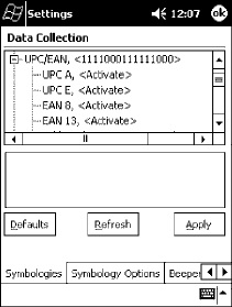
Control Panel AppletsAppendix —A
293700 Series Color Mobile Computer User’s Manual
UPC/EAN
UPC/EAN are fixed-length, numeric, continuous symbologies that use
four element widths.
Action
Tap (+) to expand the UPC/EAN parameter, select the setting to be
changed, then select an option to change this setting.
SNMP OID
1.3.6.1.4.1.1963.15.3.3.1.1.6.1
Options
UPC A 0 Not active
1 Active (default)
UPC E 0 Not active
1 Active (default)
EAN 8 0 Not active
1 Active (default)
EAN 13 0 Not active
1 Active (default)
Add-on digits 0 Not required (default)
1 Required
Add-on 2 digits 0 Not active (default)
1 Active
Add-on 5 digits (Not supported when using an imager):
0 Not active (default)
1 Active
UPC A check digit 0 Not transmitted
1 Transmitted (default)
UPC E check digit 0 Not transmitted
1 Transmitted (default)
EAN 8 check digit 0 Not transmitted
1 Transmitted (default)
EAN 13 check digit 0 Not transmitted
1 Transmitted (default)
UPC A number system 0 Not transmitted
1 Transmitted (default)
UPC E number system 0 Not transmitted
1 Transmitted (default)
UPC A re-encoding 0 UPC A transmitted as EAN 13 (default)
1 UPC A transmitted as UPC A
UPC E re-encoding 0 UPC E transmitted as UPC E (default)
1 UPC E transmitted as UPC A
EAN 8 re-encoding 0 EAN 8 transmitted as EAN 8 (default)
1 EAN 8 transmitted as EAN 13
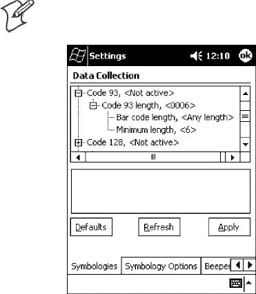
Control Panel AppletsAppendix —A
294 700 Series Color Mobile Computer User’s Manual
Code 93
Code 93 is a variable length, continuous symbology that uses four element
widths.
Action
Tap the Code 93 parameter, then select an option to change this parameter
setting. Tap (+) to access the Code 93 Lengths parameter.
SNMP OID
1.3.6.1.4.1.1963.15.3.3.1.1.7.1
Options
0 Not active (default)
1 Active
Code 93 Length
Sets the Code 93 bar code length.
Action
Tap (+) to expand the Code 93 parameter, then tap (+) to expand the
Code 93 Lengths parameter. Tap the setting to be changed, then tap an
option to change this setting.
SNMP OID
1.3.6.1.4.1.1963.15.3.3.1.1.19.1
Options
Bar code length 0 Any length (default)
1 Minimum length
Minimum length 001-254 Minimum length 1-254 (6)
Note:IfBar code length =“1”thenMinimum length is entered.
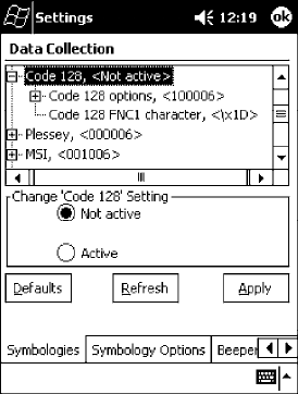
Control Panel AppletsAppendix —A
295700 Series Color Mobile Computer User’s Manual
Code 128
Code 128 is a variable-length, continuous, high-density, alphanumeric
symbology that uses multiple element widths and supports the extended
ASCII character set.
Action
Tap the Code 128 parameter, then select an option to change this parame-
ter setting. The following illustration is for a 700 Series Computer using a la-
ser scanner.
SNMP OID
1.3.6.1.4.1.1963.15.3.3.1.1.9.1
Options
0 Not active (default)
1 Active
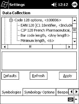
Control Panel AppletsAppendix —A
296 700 Series Color Mobile Computer User’s Manual
Code 128 Options
Set the following for the Code 128 parameter. Note that the EAN 128 ]C1
and CIP 128 French Pharmaceutical options are not available when you use
an imager with your 700 Series Computer.
Action
Tap (+) to expand the Code 128 Options parameter, select a setting, then
select an option to change this setting.
SNMP OID
None.
Options
EAN 128 ]C1 Identifier (disabled when using an imager)
0Remove
1 Include (default)
CIP 128 French Pharmaceutical (disabled when using an imager)
0 Not active (default)
1 Active
Bar code length 0 Any length (default)
1 Minimum length
Minimum length 001-254 Minimum length 1-254 (6)
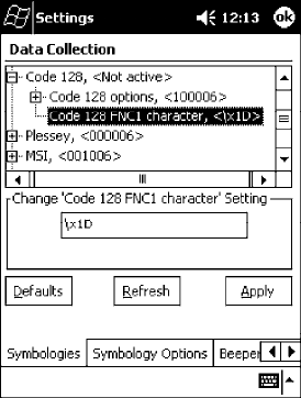
Control Panel AppletsAppendix —A
297700 Series Color Mobile Computer User’s Manual
Code 128 FNC1 Character
The Code 128 FNC1 character (EAN 128 norms) can be any ASCII char-
acter and is used as a separator when multiple identifiers and their fields
are concatenated. Note that this is not available when you use an imager with
your 700 Series Computer.
Non-printable ASCII characters can be entered using the following syntax
where HH is the hexadecimal value of the character.
\xHH
For example, the GS character, whose hexadecimal value is 1D, would be
entered as \x1D. In addition,the following characters have their own iden-
tifiers:
SBEL \a
SBS \b
SFF \f
SLF \n
SCR \r
SHT \t
SVT \v
Action
Tap (+) to expand the Code 128 parameter, then type the ASCII charac-
ters to be set for the Code 128 FNC1 character parameter.
SNMP OID
1.3.6.1.4.1.1963.15.3.3.1.1.21.1
Options
Any ASCII character (default is the GS function character - ID hex)
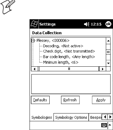
Control Panel AppletsAppendix —A
298 700 Series Color Mobile Computer User’s Manual
Plessey
Plessey is a pulse-width modulated symbology like most other bar codes. It
includes a start character, data characters, an eight-bit cyclic check digit,
and a termination bar. The code is continuous and not self-checking. You
need to configure two parameters for Plessey code: Start Code and Check
Digit. Note that this is not available when you use an imager with your 700
Series Computer.
Action
Tap (+) to expand the Plessey parameter, select the setting to be changed,
then select an option to change this setting or select an option from the
drop-down list.
SNMP OID
1.3.6.1.4.1.1963.15.3.3.1.1.10.1
Options
Decoding 0 Not active (default)
1 Active
Check digit 0 Not transmitted (default)
1 Transmitted
Bar code length 0 Any length (default)
1 Minimum length
Minimum length 001-254 Minimum bar code length 1-254 (6)
Note:IfBar code length =“1”thenMinimum length is entered.
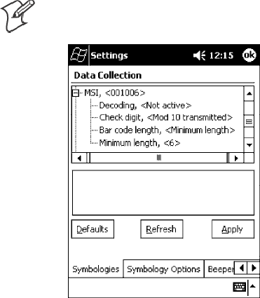
Control Panel AppletsAppendix —A
299700 Series Color Mobile Computer User’s Manual
MSI
MSI is a symbology similar to Plessey code (page 298) that includes a start
pattern, data characters, one or two check digits, and a stop pattern. Note
that this is not available when you use an imager with your 700 Series Com-
puter.
Action
Tap (+) to expand the MSI parameter, select the setting to be changed,
then select an option to change this setting or select an option from the
drop-down list.
SNMP OID
1.3.6.1.4.1.1963.15.3.3.1.1.15.1
Options
Decoding 0 Not active (default)
1 Active
Check digit 0 Mod 10 transmitted (default)
1 Mod 10 Not transmitted
2 Double Mod 10 transmitted
3 Double Mod 10 not transmitted
Bar code length 0 Any length
1 Minimum length (default)
Minimum length 001-254 Minimum length 1-254 (6)
Note:IfBar code length =“1”thenMinimum length is entered.
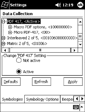
Control Panel AppletsAppendix —A
300 700 Series Color Mobile Computer User’s Manual
PDF 417
PDF 417 is a stacked two-dimensional symbology that provides the ability
to scan across rows of code. Each row consists of start/stop characters, row
identifiers, and symbol characters, which consist of four bars and four
spaces each and contain the actual data. This symbology uses error correc-
tion symbol characters appended at the end to recover loss of data.
Because the virtual wedge translates incoming data into keypad input, the
size of the keypad buffer limits the effective length of the label to 128
characters. Longer labels may be truncated. For PDF 417 labels of more
than 128 characters, you can develop an application that bypasses the key-
pad buffer.
Action
Tap the PDF 417 parameter, then select an option to change this parame-
ter setting. Tap (+) to access either the Macro PDF options parameter or
the Micro PDF 417 parameter.
SNMP OID
1.3.6.1.4.1.1963.15.3.3.1.1.17.1
Options
0 Not active
1 Active (default)
Macro PDF options
Macro PDF is used when a long message requires more than one PDF 417
label. Note that this is not available when you use an imager with your 700
Series Computer.
SSelect Buffered to store a multi-label PDF 417 message in the Sabre
buffer, thus transmitting the entire message when all labels have been
read.
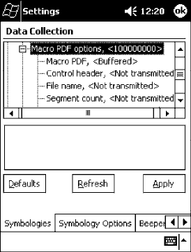
Control Panel AppletsAppendix —A
301700 Series Color Mobile Computer User’s Manual
SSelect Unbuffered for multi-label PDF 417 messages that are too long
for the Sabre buffer (memory overflow). Each part of the PDF 417 label
is transmitted separately, and the host application must then assemble
the message using the macro PDF control header transmitted with each
label. Control Header is only present in macro PDF codes and is always
transmitted with unbuffered option.
Action
Tap (+) to expand the PDF 417 parameter, tap (+) to expand the Macro
PDF parameter, select a setting to be changed, then select an option to
change this setting.
SNMP OID
1.3.6.1.4.1.1963.15.3.3.1.1.22.1
Options
Macro PDF 0 Unbuffered
1 Buffered (default)
Control header 0 Not transmitted (default)
1 Transmitted
File name 0 Not transmitted (default)
1 Transmitted
Segment count 0 Not transmitted (default)
1 Transmitted
Time stamp 0 Not transmitted (default)
1 Transmitted
Sender 0 Not transmitted (default)
1 Transmitted
Addressee 0 Not transmitted (default)
1 Transmitted
File size 0 Not transmitted (default)
1 Transmitted
Checksum 0 Not transmitted (default)
1 Transmitted
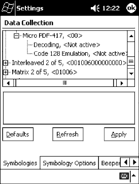
Control Panel AppletsAppendix —A
302 700 Series Color Mobile Computer User’s Manual
Micro PDF 417
Micro PDF 417 is a multi-row symbology derived from and closely based
on PDF 417 (page 300). A limited set of symbology sizes is available, to-
gether with a fixed level of error correction for each symbology size. Note
that this is not available when you use an imager with your 700 Series Com-
puter.
Action
Tap (+) to expand the PDF 417 parameter, tap (+) to expand the Micro
PDF 417 parameter, select a setting to be changed, then select an option
to change this setting.
SNMP OID
1.3.6.1.4.1.1963.15.3.3.1.1.27.1
Options
Decoding 0 Not active (default)
1 Active
Code 128 Emulation 0 Not active (default)
1 Active
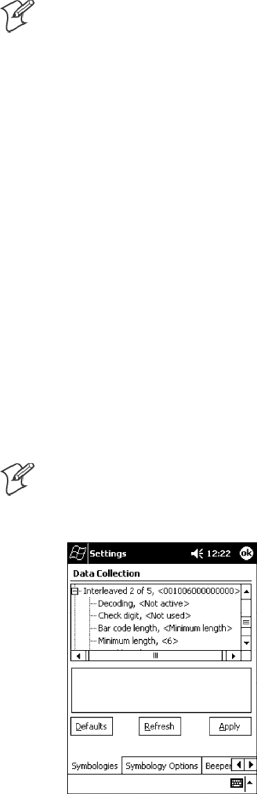
Control Panel AppletsAppendix —A
303700 Series Color Mobile Computer User’s Manual
Interleaved 2 of 5
Interleaved 2 of 5 (I 2 of 5) is a high-density, self-checking, continuous,
numeric symbology used mainly in inventory distribution and the auto-
mobile industry.
Note: An Interleaved 2 of 5 bar code label must be at least three characters
long for the 700 Series Computer to scan and decode correctly.
Action
Tap (+) to expand the Interleaved 2 of 5 parameter, select the setting to be
changed, then tap an option to change this setting or select an option from
the drop-down list.
SNMP OID
1.3.6.1.4.1.1963.15.3.3.1.1.23.1
Options
Decoding 0 Not active (default)
1 Active
Check digit 0 Not used (default)
1 Mod 10 transmitted
2 Mod 10 not transmitted
3 French CIP transmitted
4 French CIP not transmitted
Bar code length 0 Any length
1 Minimum length (default)
2 Fixed lengths
Minimum length 003-254 Minimum length 3-254 (6)
Fixed length 1 003-254 Fixed length 3-254 (0)
Fixed length 2 003-254 Fixed length 3-254 (0)
Fixed length 3 003-254 Fixed length 3-254 (0)
Note:IfBar code length =“1”thenMinimum length is entered. If Bar
code length =“2” then Fixed length 1,Fixed length 2,orFixed length 3 is
entered.
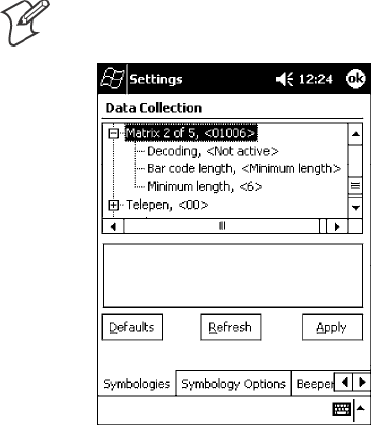
Control Panel AppletsAppendix —A
304 700 Series Color Mobile Computer User’s Manual
Matrix2of5
Matrix 2 of 5 is a numerical symbology. Note that this is not available when
you use an imager with your 700 Series Computer.
Action
Tap (+) to expand the Matrix 2 of 5 parameter, select the setting to be
changed, then tap an option to change this setting or select an option from
the drop-down list.
SNMP OID
1.3.6.1.4.1.1963.15.3.3.1.1.24.1
Options
Decoding 0 Not active (default)
1 Active
Bar code length 0 Any length
1 Minimum length (default)
Minimum length 001-254 Minimum length 1-254 (6)
Note:IfBar code length =“1”thenMinimum length is entered.
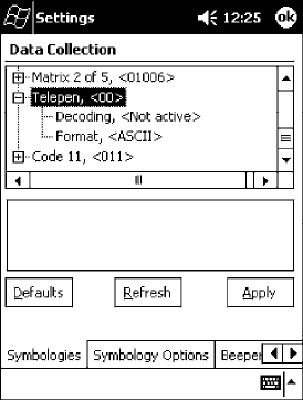
Control Panel AppletsAppendix —A
305700 Series Color Mobile Computer User’s Manual
Telepen
Telepen is an alphanumeric, case-sensitive, full ASCII symbology. Note that
this is not available when you use an imager with your 700 Series Computer.
Action
Tap (+) to expand the Telepen parameter, select the setting to be changed,
then tap an option to change this setting.
SNMP OID
1.3.6.1.4.1.1963.15.3.3.1.1.25.1
Options
Decoding 0 Not active (default)
1 Active
Format 0 ASCII (default)
1 Numeric
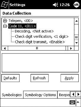
Control Panel AppletsAppendix —A
306 700 Series Color Mobile Computer User’s Manual
Code 11
Code 11 is a high density, discrete numeric symbology that is extensively
used in labeling telecommunications components and equipment. Note
that this is not available when you use an imager with your 700 Series Com-
puter.
Action
Tap (+) to expand the Code 11 parameter, select the setting to be changed,
then tap an option to change this setting.
SNMP OID
1.3.6.1.4.1.1963.15.3.3.1.1.26.1
Options
Decoding 0 Not active (default)
1 Active
Check digit verification 1 1 digit (default)
2 2 digits
Check digit transmit 0 Disable (default)
1 Enable
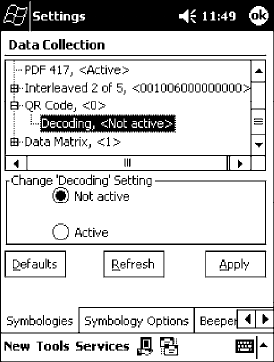
Control Panel AppletsAppendix —A
307700 Series Color Mobile Computer User’s Manual
QR Code
QR Code (Quick Response Code) is a two-dimensional matrix symbology
containing dark and light square data modules. It has position detection
patterns on three of its four corners and features direct encodation of the
Japanese Kana-Kanji character set. It can encode up to 2509 numeric or
1520 alphanumeric characters and offers three levels of error detection.
Note that this is not available when you use a laser scanner with your 700 Se-
ries Computer.
Action
Tap (+) to expand the QR Code parameter, select the setting to be
changed, then tap an option to change this setting or select an option from
the drop-down list.
SNMP OID
1.3.6.1.4.1.1963.15.3.3.1.1.35.1
Options
Decoding 0 Not active
1 Active (default)
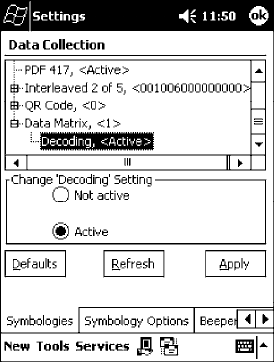
Control Panel AppletsAppendix —A
308 700 Series Color Mobile Computer User’s Manual
Data Matrix
A two-dimensional matrix symbology, which is made of square modules
arranged within a perimeter finder pattern. The symbology utilizes Error
Checking and Correcting (ECC) algorithm with selectable levels for data
error recovery and Cyclic Redundancy Check algorithm to validate the da-
ta. The character set includes either 128 characters conforming to ISO
646 (ANSI X3.4 - 1986) or 256 extended character set. Maximum capac-
ity of a symbol is 2335 alphanumeric characters, 1556 8-bit byte charac-
ters or 3116 numeric digits. Note that this is not available when you use a
laser scanner with your 700 Series Computer.
Action
Tap (+) to expand the Data Matrix parameter, select the setting to be
changed, then tap an option to change this setting or select an option from
the drop-down list.
SNMP OID
1.3.6.1.4.1.1963.15.3.3.1.1.34.1
Options
Decoding 0 Not active
1 Active (default)
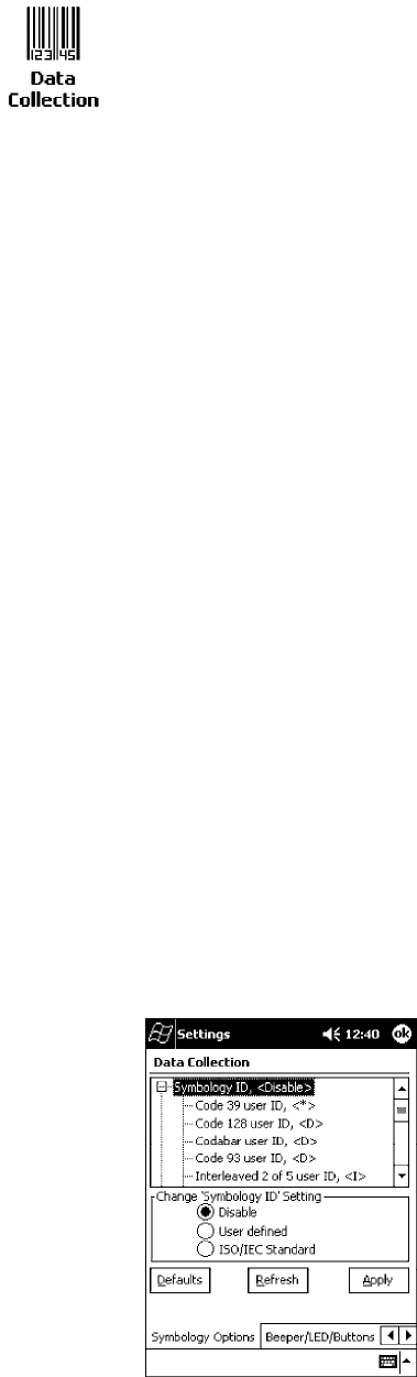
Control Panel AppletsAppendix —A
309700 Series Color Mobile Computer User’s Manual
Symbology Options
To access the settings from the 700 Series Computer, tap Start →Settings
→the System tab →the Data Collection icon to access its control panel
applet.
Use the right and left arrows to scroll to the Symbology Options tab, then
tap this tab to access its parameters. The following are parameters for bar
code symbology options. Note that these are listed in the order of their
appearance within the Symbology Options tab.
Symbology ID
Identifies the bar code symbology in which data has been encoded by pre-
pending a user-specified symbology identifier to the data. You can prepend
one of these types of character strings to identify the symbology:
SUser-defined ASCII Character (Option 1):
A user-defined symbology identifier is a single ASCII character. You can
assign a custom identifier character to each bar code symbology. Note
that this is not available when you use an imager with your 700 Series
Computer.
SAIM ISO/IEC Standard (Option 2 - Required to define symbology IDs):
The AIM Standard has a three-character structure which indicates the
symbology and optional features. See the AIM ISO/IEC Standard for
more information.
Action
Select Symbology ID, then select an option to change this parameter set-
ting. Tap (+) to expand the Symbology ID parameter, then select any of
the user ID parameters listed. See the top of the next page for a sample screen
of the Code 39 user ID.
SNMP OID
1.3.6.1.4.1.1963.15.3.3.4.1.22.1
Options
0 Disable (default)
1 User defined (disabled when using an imager)
2 ISO/IEC Standard
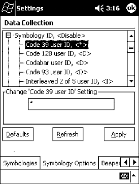
Control Panel AppletsAppendix —A
310 700 Series Color Mobile Computer User’s Manual
Code 39 User ID
If “1” was selected in the Symbology ID parameter, you can set your own
ASCII character to identify Code 39 bar code data. Note that this is not
available when you use an imager with your 700 Series Computer.
Action: Tap (+) to expand the Symbology ID parameter, select the Code 39 user
ID parameter, then enter a user ID value to change this parameter setting.
SNMP OID: 1.3.6.1.4.1.1963.15.3.3.4.1.3.1
Options: xwhere xis a single ASCII character. Default is asterisk (*).
Code 128 User ID
If “1” was selected in the Symbology ID parameter, you can set your own
ASCII character to identify Code 128 bar code data. Note that this is not
available when you use an imager with your 700 Series Computer.
Action: Tap (+) to expand the Symbology ID parameter, select the Code 128 user
ID parameter, then enter a user ID value to change this parameter setting.
SNMP OID: 1.3.6.1.4.1.1963.15.3.3.4.1.5.1
Options: xwhere xis a single ASCII character. Default is asterisk (*).
Codabar User ID
If “1” was selected in the Symbology ID parameter, you can set your own
ASCII character to identify Codabar bar code data. Note that this is not
available when you use an imager with your 700 Series Computer.
Action: Tap (+) to expand the Symbology ID parameter, select the Codabar user
ID parameter, then enter a user ID value to change this parameter setting.
SNMP OID: 1.3.6.1.4.1.1963.15.3.3.4.1.2.1
Options: xwhere xis a single ASCII character. Default is D.
Control Panel AppletsAppendix —A
311700 Series Color Mobile Computer User’s Manual
Code 93 User ID
If “1” was selected in the Symbology ID parameter, you can set your own
ASCII character to identify Code 93 bar code data. Note that this is not
available when you use an imager with your 700 Series Computer.
Action: Tap (+) to expand the Symbology ID parameter, select the Code 93 user
ID parameter, then enter a user ID value to change this parameter setting.
SNMP OID: 1.3.6.1.4.1.1963.15.3.3.4.1.4.1
Options: xwhere xis a single ASCII character. Default is asterisk (*).
Interleaved 2 of 5 User ID
If “1” was selected in the Symbology ID parameter, you can set your own
ASCII character to identify Interleaved 2 of 5 bar code data. Note that this
is not available when you use an imager with your 700 Series Computer.
Action: Tap (+) to expand the Symbology ID parameter, select the Interleaved 2
of 5 user ID parameter, then enter a user ID value to change this parame-
ter setting.
SNMP OID: 1.3.6.1.4.1.1963.15.3.3.4.1.10.1
Options: xwhere xis a single ASCII character. Default is I (not lowercase L).
PDF-417 User ID
If “1” was selected in the Symbology ID parameter, you can set your own
ASCII character to identify PDF 417 bar code data. Note that this is not
available when you use an imager with your 700 Series Computer.
Action: Tap (+) to expand the Symbology ID parameter, select the PDF 417 user
ID parameter, then enter a user ID value to change this parameter setting.
SNMP OID: 1.3.6.1.4.1.1963.15.3.3.4.1.12.1
Options: xwhere xis a single ASCII character. Default is an asterisk (*).
MSI User ID
If “1” was selected in the Symbology ID parameter, you can set your own
ASCII character to identify MSI bar code data. Note that this is not avail-
able when you use an imager with your 700 Series Computer.
Action: Tap (+) to expand the Symbology ID parameter, select the MSI user ID
parameter, then enter a user ID value to change this parameter setting.
SNMP OID: 1.3.6.1.4.1.1963.15.3.3.4.1.11.1
Options: xwhere xis a single ASCII character. Default is D.
Control Panel AppletsAppendix —A
312 700 Series Color Mobile Computer User’s Manual
Plessey User ID
If “1” was selected in the Symbology ID parameter, you can set your own
ASCII character to identify Plessey bar code data. Note that this is not avail-
able when you use an imager with your 700 Series Computer.
Action: Tap (+) to expand the Symbology ID parameter, select the Plessey user ID
parameter, then enter a user ID value to change this parameter setting.
SNMP OID: 1.3.6.1.4.1.1963.15.3.3.4.1.13.1
Options: xwhere xis a single ASCII character. Default is D.
Standard 2 of 5 User ID
If “1” was selected in the Symbology ID parameter, you can set your own
ASCII character to identify Standard 2 of 5 bar code data. Note that this is
not available when you use an imager with your 700 Series Computer.
Action: Tap (+) to expand the Symbology ID parameter, select the Standard 2 of
5userIDparameter, then enter a user ID value to change this parameter
setting.
SNMP OID: 1.3.6.1.4.1.1963.15.3.3.4.1.23.1
Options: xwhere xis a single ASCII character. Default is D.
UPC A User ID
If “1” was selected in the Symbology ID parameter, you can set your own
ASCII character to identify UPC-A (Universal Product Code) bar code
data. Note that this is not available when you use an imager with your 700
Series Computer.
Action: Tap (+) to expand the Symbology ID parameter, select the UPC A user ID
parameter, then enter a user ID value to change this parameter setting.
SNMP OID: 1.3.6.1.4.1.1963.15.3.3.4.1.6.1
Options: xwhere xis a single ASCII character. Default is A.
UPC E User ID
If “1” was selected in the Symbology ID parameter, you can set your own
ASCII character to identify UPC-E bar code data. Note that this is not
available when you use an imager with your 700 Series Computer.
Action: Tap (+) to expand the Symbology ID parameter, select the UPC E user ID
parameter, then enter a user ID value to change this parameter setting.
SNMP OID: 1.3.6.1.4.1.1963.15.3.3.4.1.7.1
Options: xwhere xis a single ASCII character. Default is E.
Control Panel AppletsAppendix —A
313700 Series Color Mobile Computer User’s Manual
EAN 8 User ID
If “1” was selected in the Symbology ID parameter, you can set your own
ASCII character to identify EAN-8 bar code data. Note that this is not
available when you use an imager with your 700 Series Computer.
Action: Tap (+) to expand the Symbology ID parameter, select the EAN 8 user ID
parameter, then enter a user ID value to change this parameter setting.
SNMP OID: 1.3.6.1.4.1.1963.15.3.3.4.1.8.1
Options: xwhere xis a single ASCII character. Default is \xFF.
EAN 13 User ID
If “1” was selected in the Symbology ID parameter, you can set your own
ASCII character to identify EAN-13 (European Article Numbering) bar
code data. Note that this is not available when you use an imager with your
700 Series Computer.
Action: Tap (+) to expand the Symbology ID parameter, select the EAN 13 user
ID parameter, then enter a user ID value to change this parameter setting.
SNMP OID: 1.3.6.1.4.1.1963.15.3.3.4.1.9.1
Options: xwhere xis a single ASCII character. Default is F.
Matrix 2 of 5 User ID
If “1” was selected in the Symbology ID parameter, you can set your own
ASCII character to identify Matrix 2 of 5 bar code data. Note that this is
not available when you use an imager with your 700 Series Computer.
Action: Tap (+) to expand the Symbology ID parameter, select the Matrix 2 of 5
user ID parameter, then enter a user ID value to change this parameter
setting.
SNMP OID: 1.3.6.1.4.1.1963.15.3.3.4.1.24.1
Options: xwhere xis a single ASCII character. Default is D.
Telepen User ID
If “1” was selected in the Symbology ID parameter, you can set your own
ASCII character to identify Telepen bar code data. Note that this is not
available when you use an imager with your 700 Series Computer.
Action: Tap (+) to expand the Symbology ID parameter, select the Telepen user
ID parameter, then enter a user ID value to change this parameter setting.
SNMP OID: 1.3.6.1.4.1.1963.15.3.3.4.1.25.1
Options: xwhere xis a single ASCII character. Default is an asterisk (*).
Control Panel AppletsAppendix —A
314 700 Series Color Mobile Computer User’s Manual
Code 11 User ID
If “1” was selected in the Symbology ID parameter, you can set your own
ASCII character to identify Code 11 bar code data. Note that this is not
available when you use an imager with your 700 Series Computer.
Action: Tap (+) to expand the Symbology ID parameter, select the Code 11 user
ID parameter, then enter a user ID value to change this parameter setting.
SNMP OID: 1.3.6.1.4.1.1963.15.3.3.4.1.16.1
Options: xwhere xis a single ASCII character. Default is asterisk (*).
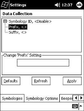
Control Panel AppletsAppendix —A
315700 Series Color Mobile Computer User’s Manual
Prefix
Prepends a string of up to 20 ASCII characters to all scanned data.
Action
Tap the Prefix parameter, then enter a prefix value to change this parame-
ter setting.
SNMP OID
1.3.6.1.4.1.1963.15.3.3.4.1.29.1
Options
Acceptable values are up to 20 ASCII characters.
Embedded null (<NUL >) characters are not allowed.
Default is no characters (disabled).
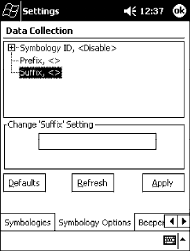
Control Panel AppletsAppendix —A
316 700 Series Color Mobile Computer User’s Manual
Suffix
Appends a string of up to 20 ASCII characters to all scanned data.
Action
Tap the Suffix parameter, then enter a suffix value to change this parame-
ter setting.
SNMP OID
1.3.6.1.4.1.1963.15.3.3.4.1.30.1
Options
Acceptable values are up to 20 ASCII characters. Embedded null (<NUL
>) characters are not allowed. Default is no characters (disabled).

Control Panel AppletsAppendix —A
317700 Series Color Mobile Computer User’s Manual
Beeper/LED
To access the settings from the 700 Series Computer, tap Start →Settings
→the System tab →the Data Collection icon to access its control panel
applet.
Use the right and left arrows to scroll to the Beeper/LED tab, then tap this
tab to access its parameters.
Most of these functions are not available when using an imager. The following
table shows which functions are supported either by an imager or by a laser
scanner.
Beeper Function Imager Laser Scanner
Beeper Volume XX
Beeper Frequency X
Good Read Beeps X
Good Read Beep Duration X
The following are parameters for features on the 700 Series Computer.
Note that these are listed in the order of their appearance.
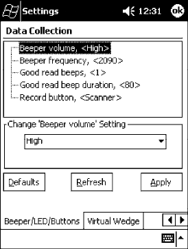
Control Panel AppletsAppendix —A
318 700 Series Color Mobile Computer User’s Manual
Beeper Volume
Sets the volume for the good read beep.
Action
Tap the Beeper volume parameter, then select an option to change this pa-
rameter setting.
SNMP OID
1.3.6.1.4.1.1963.15.3.1.4.1.6.1
Laser Scanner Options
0Low
1High(default)
2 Medium
3 Off
4 Vibrate
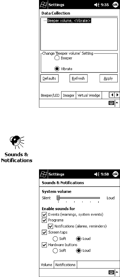
Control Panel AppletsAppendix —A
319700 Series Color Mobile Computer User’s Manual
Imager Options
1 Beeper (default)
4 Vibrate
Silencing the Beeper Volume
To turn the beeper off, tap Start →Settings →the Personal tab →
Sounds and Notifications →the Volume tab, drag the System volume
slider bar to the left “Silent” position, then tap ok to exit this applet.
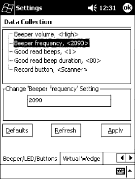
Control Panel AppletsAppendix —A
320 700 Series Color Mobile Computer User’s Manual
Beeper Frequency
Sets the frequency for the good read beep. Note that this is not available
when you use an imager with your 700 Series Computer.
Action
Tap the Beeper frequency parameter, then enter a frequency value to
change this parameter setting.
SNMP OID
1.3.6.1.4.1.1963.15.3.1.4.1.7.1
Options
1000-4095 (default is 2090)
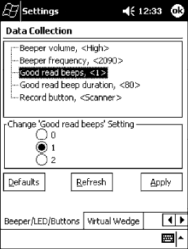
Control Panel AppletsAppendix —A
321700 Series Color Mobile Computer User’s Manual
Good Read Beeps
Sets the number of good read beeps. Note that this is not available when you
use an imager with your 700 Series Computer.
Action
Tap the Good read beeps parameter, then select an option to change this
parameter setting.
SNMP OID
1.3.6.1.4.1.1963.15.3.1.4.1.8.1
Options
0 No beeps
1 One beep (default)
2 Two beeps
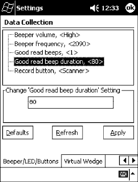
Control Panel AppletsAppendix —A
322 700 Series Color Mobile Computer User’s Manual
Good Read Beep Duration
Sets the duration of the good read beep. Note that this is not available when
you use an imager with your 700 Series Computer.
Action
Tap the Good read beep duration parameter, then enter a duration value
to change this parameter setting.
SNMP OID
1.3.6.1.4.1.1963.15.3.1.4.1.9.1
Options
0`2550 Beep duration in milliseconds. (default is 80)
Control Panel AppletsAppendix —A
323700 Series Color Mobile Computer User’s Manual
Imager
To access the settings from the 700 Series Computer, tap Start →Settings
→the System tab →the Data Collection icon to access its control panel
applet.
Use the right and left arrows to scroll to the Imager tab, then tap this tab
to access its parameters.
The following are parameters for the imager. Note that these are listed in
the order of their appearance within the Imager tab.
Aimer LED duration
The Aimer LED duration controls the time the Aimer LED is turned on
when the scan button is pressed. After this time, images are captured for
decoding. The purpose is to position the Aimer LED on the bar code sym-
bol before attempting to decode the bar code. Note that this is not available
when you use a laser scanner with your 700 Series Computer.
Action
Tap the Aimer LED duration parameter, then enter a value to change this
setting. Note that values must be in 50 ms increments, such as 500, 650,
or 32500. Values not entered in 50 ms increments will be rounded down.
For example, 2489 ms would be rounded down to 2450 ms, 149 ms
would be rounded down to 100 ms, etc..
SNMP OID
1.3.6.1.4.1.1963.15.3.3.3.1.1.21.1
Options
0-65500 ms (Default is 0)
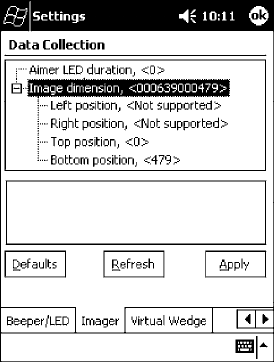
Control Panel AppletsAppendix —A
324 700 Series Color Mobile Computer User’s Manual
Image Dimension
The image dimensions control the horizontal size of the image for decod-
ing. This can restrict the image to one bar code when otherwise, there
might be more than one bar code in the image to be decoded. Note that
this is not available when you use a laser scanner with your 700 Series Com-
puter.
Action
Tap the Image dimension parameter, select the position to be changed,
then tap an option or enter a value to change this position.
SNMP OID
1.3.6.1.4.1.1963.15.3.3.3.1.1.22.1
Options
Left position 0 Not supported
Right position 0 Not supported
Top position 0-478 Position in pixels (0)
Bottom position 0-479 Position in pixels (479)
Control Panel AppletsAppendix —A
325700 Series Color Mobile Computer User’s Manual
Virtual Wedge
To access the settings from the 700 Series Computer, tap Start →Settings
→the System tab →the Data Collection icon to access its control panel
applet.
Use the right and left arrows to scroll to the Virtual Wedge tab, then tap
this tab to access its parameters.
The following are parameters for the virtual wedge scanner. Note that these
are listed in the order of their appearance within the Virtual Wedge tab.
Virtual Wedge
Enables or disables the virtual wedge for the internal scanner. The virtual
wedge retrieves scanned Automatic Data Collection (ADC) data and sends
it to the keypad driver so that the 700 Series Computer can receive and
interpret the data as keypad input.
Because the virtual wedge translates incoming data into keypad input, the
size of the keypad buffer limits the effective length of the label to 128
characters. Longer labels may be truncated. For labels of more than 128
characters, you need to develop an application that bypasses the keypad
buffer.
Action
Tap the Virtual Wedge parameter, then tap an option to change this pa-
rameter setting.
SNMP OID
1.3.6.1.4.1.1963.15.3.2.1.1.2.1
Options
0 Disable
1 Enable (default)
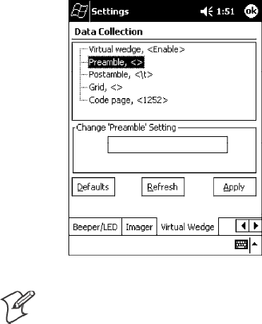
Control Panel AppletsAppendix —A
326 700 Series Color Mobile Computer User’s Manual
Preamble
Sets the preamble that precedes any data you scan with the 700 Series
Computer. Common preambles include a data location number or an op-
erator number.
Action
Tap the Preamble parameter, then enter a preamble value to change this
parameter setting.
SNMP OID
1.3.6.1.4.1.1963.15.3.2.1.1.3.1
Syntax
ADdata
where data is acceptable values up to 31 ASCII characters. Embedded null
(<NUL >) characters are not allowed. Default is no characters (disabled).
Note: When you enter the AD command without data, the preamble is
disabled. If you want to use quotation marks or the following combina-
tions of characters as part of the appended data, separate those characters
from the AD command with quotes. If you do not use quotes as described
here, the 700 Series Computer will interpret the characters as another con-
figuration command:
AD
AE
AF
KC
BV
EX
DF
EXAMPLE:
To use the two-character string BV as a preamble, scan this command (as a
Code 39 label) or send this command through the network: $+AD“BV”
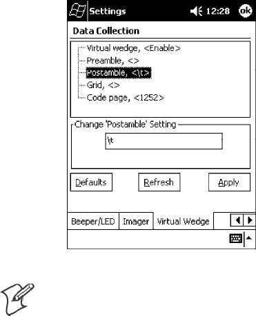
Control Panel AppletsAppendix —A
327700 Series Color Mobile Computer User’s Manual
Postamble
Sets the postamble that is appended to any data you scan with the 700 Se-
ries Computer. Common postambles include cursor controls, such as tabs
or carriage return line feeds.
Action
Tap the Postamble parameter, then enter a postamble value to change this
parameter setting.
SNMP OID
1.3.6.1.4.1.1963.15.3.2.1.1.4.1
Syntax
AEdata
where data is any acceptable values up to 31 ASCII characters. Embedded
null (<NUL >) characters are not allowed. Default is the tab character (\t).
Note: When you enter the AE command without data, the postamble is
disabled. If you want to use quotation marks or the following combina-
tions of characters as part of the appended data, separate those characters
from the AE command with quotes. If you do not use quotes as described
here, the 700 Series Computer will interpret the characters as another con-
figuration command.
AD
AE
AF
KC
BV
EX
DF
EXAMPLE:
To use the two-character string BV as a postamble, scan this command (as
a Code 39 label) or send this command through the network: $+AE“BV”
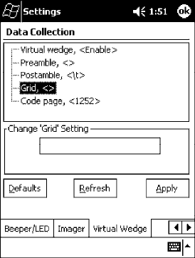
Control Panel AppletsAppendix —A
328 700 Series Color Mobile Computer User’s Manual
Grid
Sets the virtual wedge grid, which filters the data coming from this 700
Series Computer. The data server supports data filtering, which allows you
to selectively send scanned data. The virtual wedge grid is similar to the
“format” argument of the C Runtime Library scan function.
Action
Tap the Grid parameter, then enter a grid value to change this parameter
setting.
SNMP OID
1.3.6.1.4.1.1963.15.3.2.1.1.5.1
Syntax
AF<symID> filter-expression= > editing-expression
where:
S<symID>
The AIM symbology ID.
Sfilter-expression
Any character string that includes valid filter expression values, and edit-
ing-expression is any character string that includes valid editing expres-
sion values.
S<width>
Any positive integer or NULL. A NULL width means that the field type
(defined next) applies all the way to the end of the data string. A non-
NULL width means that the field applies to that many characters of da-
ta. The grid can be up to 240 characters in length. Default is NULL.
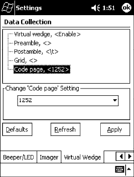
Control Panel AppletsAppendix —A
329700 Series Color Mobile Computer User’s Manual
Code Page
Sets the virtual wedge code page. The code page controls the translation
from the character set of the raw collected data to Unicode, which is the
character set expected by Windows CE applications. The default code page
is 1252, which is the Windows Latin 1 (ANSI) character set.
Action
Tap the Code Page parameter, then select an option to change this param-
eter setting.
SNMP OID
1.3.6.1.4.1.1963.15.3.2.1.1.6.1
Options
The only acceptable value for the code page parameter is “1252,” which is
the default.
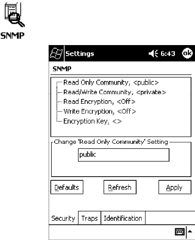
Control Panel AppletsAppendix —A
330 700 Series Color Mobile Computer User’s Manual
SNMP Control Panel Applet
Simple Network Management Protocol (SNMP) parameters include iden-
tification information, security encryption, security community strings,
and traps.
To access the settings from the 700 Series Computer, tap Start →Settings
→the System tab →the SNMP icon to access its control panel applet.
Tap a tab to access its menus. These tabs represent three groups of settings
or parameters:
SSecurity (starting on the next page)
STraps (starting on page 336)
SIdentification (starting on page 338)
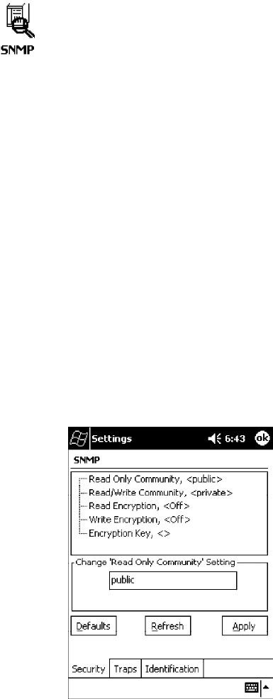
Control Panel AppletsAppendix —A
331700 Series Color Mobile Computer User’s Manual
Security
To access the settings from the 700 Series Computer, tap Start →Settings
→the System tab →the SNMP icon →the Security tab to access its
parameters.
The following are parameters that affect encryption and community
strings. Note that these are listed in the order of their appearance within the
Security tab.
Read Only Community
Sets the read-only community string for this 700 Series Computer, which
is required for processing of SNMP get and get next requests.
Action
Tap the Read Only Community parameter, then enter a community string
to change this parameter setting.
SNMP OID
1.3.6.1.4.1.1963.10.5.1.2.0
Options
The read-only community string can be up to 128 ASCII characters. De-
fault is Public.
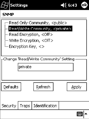
Control Panel AppletsAppendix —A
332 700 Series Color Mobile Computer User’s Manual
Read/Write Community
Sets the read/write community string, which is required for processing of
SNMP set requests by this 700 Series Computer. An SNMP packet with
this name as the community string will also process SNMP get and next
requests.
Action
Tap the Read/Write Community parameter, then enter a community
string to change this parameter setting.
SNMP OID
1.3.6.1.4.1.1963.10.5.1.3.0
Options
The read/write community string can be up to 128 ASCII characters. De-
fault is Private.
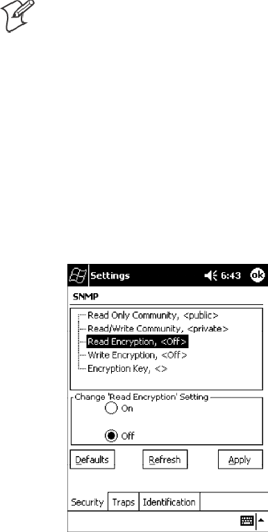
Control Panel AppletsAppendix —A
333700 Series Color Mobile Computer User’s Manual
Read Encryption
Sets the packet-level mode of security for SNMP read-only requests. If you
enable read encryption, all received SNMP get and get next packets have
to be encrypted or the packet will not be authorized. If encryption is en-
abled, you can only use software provided by Intermec Technologies.
Note: To enable security encryption, you also need to set the Security En-
cryption Key (page 335).
Action
Tap the Read Encryption parameter, then select an option to change this
parameter setting.
SNMP OID
1.3.6.1.4.1.1963.10.5.1.4.0
Options
1 On SNMP get and get next packets must be encrypted
2 Off SNMP packets do not have to be encrypted (default)
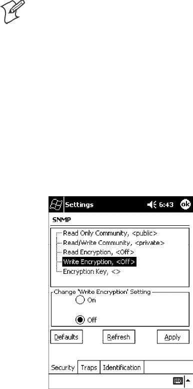
Control Panel AppletsAppendix —A
334 700 Series Color Mobile Computer User’s Manual
Write Encryption
Sets the packet-level mode of security for SNMP read/write requests. If
you enable write encryption, all SNMP packets that are received with the
read/write community string have to be encrypted or the packet will not
be authorized. You need to use software from Intermec Technologies that
supports encryption.
Note: To enable security encryption, you also need to set the Security En-
cryption Key (page 335).
Action
Tap the Write Encryption parameter, then select an option to change this
parameter setting.
SNMP OID
1.3.6.1.4.1.1963.10.5.1.5.0
Options
1 On SNMP packets must be encrypted
2 Off SNMP packets do not have to be encrypted (default)
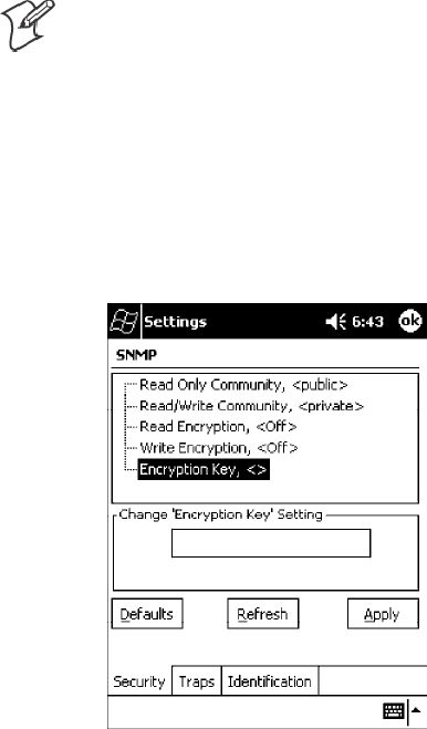
Control Panel AppletsAppendix —A
335700 Series Color Mobile Computer User’s Manual
Encryption Key
Identifies the key that this 700 Series Computer uses to encrypt or deci-
pher SNMP packets. Encryption is used only by software provided by In-
termec Technologies. If encryption is enabled, SNMP management plat-
forms will not be able to communicate with the 700 Series Computer. The
encryption key is returned encrypted.
Action
Tap the Encryption Key parameter, then enter a security encryption key
value to change this parameter setting.
Note: You also need to set either Read Encryption (page 333) or Write
Encryption (page 334) or both.
SNMP OID
1.3.6.1.4.1.1963.10.5.1.6.0
Options
The encryption key can be from 4 to 20 ASCII characters. Default is
NULL.
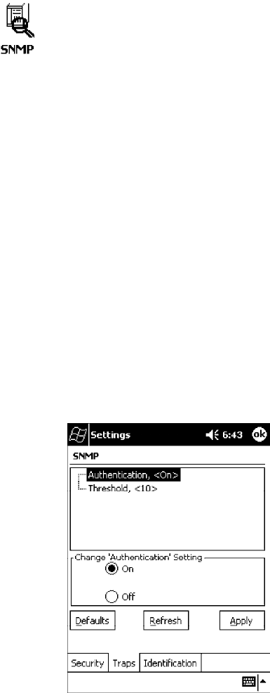
Control Panel AppletsAppendix —A
336 700 Series Color Mobile Computer User’s Manual
Traps
To access the settings from the 700 Series Computer, tap Start →Settings
→the System tab →the SNMP icon →the Traps tab to access its
parameters.
The following are authentication and threshold parameters for traps. Note
that these are listed in the order of their appearance within the Traps tab.
Authentication
Determines whether to send authentication traps. When trap authentica-
tion is enabled, an authentication trap is sent if an SNMP packet is re-
ceived by the master agent with an invalid community string.
Action
Tap the Authentication parameter, then select an option to change this
parameter setting.
SNMP OID
1.3.6.1.4.1.1963.10.5.2.2.0
Options
1On(default)
2 Off
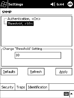
Control Panel AppletsAppendix —A
337700 Series Color Mobile Computer User’s Manual
Threshold
Determines the maximum number of traps per second that the master
agent generates. If the threshold is reached, the trap will not be sent.
Action
Tap the Threshold parameter, then enter a threshold value to change this
parameter setting.
SNMP OID
1.3.6.1.4.1.1963.10.5.2.3.0
Options
Any positive integer value. Default is 10.
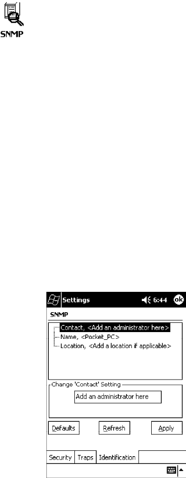
Control Panel AppletsAppendix —A
338 700 Series Color Mobile Computer User’s Manual
Identification
To access the settings from the 700 Series Computer, tap Start →Settings
→the System tab →the SNMP icon →the Identification tab to access
its parameters.
The following are parameters for contact, location, and name information
for support purposes. Note that these are listed in the order of their appear-
ance within the Identification tab.
Contact
Sets the contact information for the person responsible for this 700 Series
Computer.
Action
Tap the Contact parameter, then enter the name of your contact represen-
tative to change this parameter setting.
SNMP OID
1.3.6.1.2.1.1.4.0
Options
The identification contact may be up to 255 ASCII characters. Default is
no characters or blank.
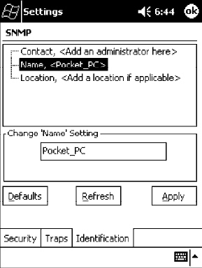
Control Panel AppletsAppendix —A
339700 Series Color Mobile Computer User’s Manual
Name
Sets the assigned name for this 700 Series Computer.
Action
Tap the Name parameter, then enter the name of your 700 Series Com-
puter to change this parameter setting.
SNMP OID
1.3.6.1.2.1.1.5.0
Options
The identification name may be up to 255 ASCII characters. Default is no
characters or blank.
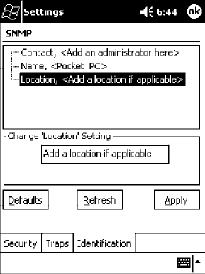
Control Panel AppletsAppendix —A
340 700 Series Color Mobile Computer User’s Manual
Location
Sets the identification location for this 700 Series Computer, such as
“Shipping.”
Action
Tap the Location parameter, then enter the location of where your 700
Series Computer to change this parameter setting.
SNMP OID
1.3.6.1.2.1.1.6.0
Options
The identification location may be up to 255 ASCII characters. Default is
no characters or blank.
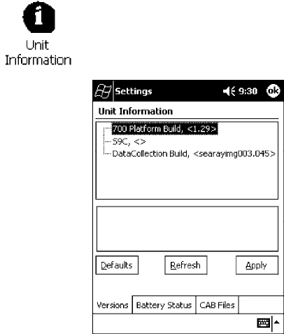
Control Panel AppletsAppendix —A
341700 Series Color Mobile Computer User’s Manual
Unit Information Control Panel Applet
Unit Information is a read-only control panel applet that provides informa-
tion about your 700 Series Computer, such as software version builds,
available CAB files, and the internal battery status.
This control panel applet is only available in the 700 Series Computer if
Intermec Content is enabled, the Plus region is enabled and installed, and
a laser scanner is installed.
To access the settings from the 700 Series Computer, tap Start →Settings
→the System tab →the Unit Information icon to access its control panel
applet.
Tap a tab to access its menus. These tabs represent three groups of settings
or parameters:
SVersions (starting on the next page)
SBattery Status (starting on page 343)
SCAB Files (starting on page 344)

Control Panel AppletsAppendix —A
342 700 Series Color Mobile Computer User’s Manual
Versions
You can view the latest software build version on your 700 Series
Computer by accessing the Unit Information control panel applet.
To access the settings from the 700 Series Computer, tap Start →Settings
→the System tab →the Unit Information icon →the Versions tab to
view the latest software build version. Tap ok to exit this information.
Below are some of the software applications you may find on this screen:
S700 Platform Build:
Shows the latest development or released version of the software build
for the 700 Series Computer.
SS9C:
Provides the name and version of the scanner file built into this 700 Se-
ries Computer, along with the current CPU version.
SDataCollection Build:
Shows the latest development or released version of the software build
for the Data Collection control panel applet.
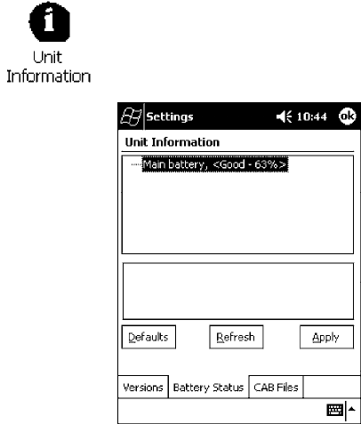
Control Panel AppletsAppendix —A
343700 Series Color Mobile Computer User’s Manual
Battery Status
You can view the battery status for your 700 Series Computer by accessing
the Unit Information control panel applet. Unit Manager applications are
available on the 700 Series Color Unit Manager CD-ROM.Formore
information, consult your Intermec sales representative.
To access the settings from the 700 Series Computer, tap Start →Settings
→the System tab →the Unit Information icon →the Battery Status tab
to view the current status. Tap ok to exit this information.
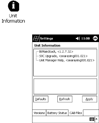
Control Panel AppletsAppendix —A
344 700 Series Color Mobile Computer User’s Manual
CAB Files
You can view the latest developer or released version of each CAB file from
Intermec Technologies Corporation that are installed in your 700 Series
Computer via the Unit Information control panel applet. Custom CAB
files are not displayed in this applet. See the Software Tools User’ s Manual for
more information about these files.
To access the information from the 700 Series Computer, tap Start →
Settings →the System tab →the Unit Information icon →the CAB
Files tab to view the current CAB file versions. Tap ok to exit this
information.
When a CAB file is built, a registry entry is created with a build number
for that file. This CAB Files control panel applet looks for a registry key
for each CAB file installed. When the registry entry is found, the CAB file
name and version number information are displayed. If a CAB file has not
been installed, then its information is not displayed.
Below is a list of CAB files from Intermec Technologies that are available
for your 700 Series Computer with their latest developer or released ver-
sion of the software build. Should you need to add any of these to your
700 Series Computer, contact an Intermec representative.
SBtMainStack:
Installation of the Main Bluetooth Stack is handled automatically as part
of the operating system boot-up procedure. See Chapter 4, “Network
Support,” for more information about Bluetooth wireless printing.
SComm Port Wedge:
The software build for the Comm Port Wedge. Note that the Comm Port
Wedge CAB file is available on the 700C Tools CD.
SNPCPTest:
This installs a NorandPortable Communications Protocol (NPCP)
Printing test application which will print to an Intermec4815, 4820,
or 6820 Printer. See Chapter 5, “Printer Support,” for more information.

Control Panel AppletsAppendix —A
345700 Series Color Mobile Computer User’s Manual
SPDWPM0C:
This is the installer for the Wireless Printing Demo application. To run
this demonstration, tap Start →Programs →the Wireless Printing
Demo icon. Press Help in the demo application for more information.
SS9C Upgrade:
Installs the files needed to upgrade the S9C scanner firmware. See the
Recovery CD Help for more information about upgrading the firmware.
SSDK:
Installs the Intermec Software Developer’ s Kit (SDK). See the SDK
User’ s Manual for more information.
SUnit Manager:
Installs the Unit Manager application which provides tools for remotely
managing the 700 Series Computer. Unit Manager applications are
available on the 700 Series Color Unit Manager CD-ROM. For more in-
formation, consult your Intermec sales representative.
SUnit Manager Help:
Installs the online help for the Unit Manager application.
SWinCfg:
Configures the NRINET.INI file, launches the NRINet client, and
loads and unloads the LAN and WLAN device drivers. See the Windows
95 and Windows CE Configuration Utilities Reference Manual (P/N:
978-054-010) for more information.
SWireless Printing Sample:
Installs a sample application that developers can use for reference when
they are developing their own Wireless Printing applications. The source
code for this application is included as part of the Wireless Printing
SDK on the 700C Tools CD. See the SDK User’ s Manual for more infor-
mation.
SActiveX Control Tools:
This lists some of the CAB files that may be available with which to
install ActiveX Control Tools. See the SDK Online Help for more informa-
tion.
SAXCommunication:
Communication controls that transmit or receive messages from in-
put connections.
SAXFileTransfer:
File transfer controls that transmit and receive files using the Trivial
File Transfer Protocol (TFTP).
SAXReaderCommand:
Reader command functions that modify and retrieve configuration
information from your 700 Series Computer.
SAXVWedge:
The virtual wedge control that retrieves scanned ADC data and sends
it to the keyboard driver to interpret data as keyboard input.
Control Panel AppletsAppendix —A
346 700 Series Color Mobile Computer User’s Manual

347700 Series Color Mobile Computer User’s Manual
Unit Manager
B
Configuration parameters are also configurable using a Unit Manager ap-
plication which accesses the 700 Series Computer through a web browser
on your desktop PC via the SRDEVMGMT.CAB file.
Unit Manager applications are available on the 700 Series Color Unit
Manager CD-ROM. For more information, consult your Intermec sales
representative.
Note: Parameter information, such as SNMP OID and options, is detailed
in Appendix A, “Control Panel Applets.”

Unit ManagerAppendix —B
348 700 Series Color Mobile Computer User’s Manual
Data Collection
Within the Unit Manager, click Configuration from the left navigation
bar, then click the Data Collection icon to access any of these tabs:
Symbologies, Symbology ID, Beeper/LED, or Virtual Wedge.
Symbologies
Within the Unit Manager, select Configuration Management →Data
Collection, then click the Symbologies tab to access the following parame-
ters. Options for these parameters are listed on the page provided. These
are listed in alphabetical order.
SCodabar (page 292)
SCode 11 (page 306)
SCode 128 (page 295)
SCode 128 Options (page 296)
SCode 128 FNC1 Character (page 297)
SCode 39 (page 290)
SCode 93 (page 294)
SCode 93 Length (page 294)
SData Matrix (page 308)
SInterleaved 2 of 5 (page 303)
SMatrix 2 of 5 (page 304)
SMSI (page 299)
SPDF 417 (page 300)
SMacro PDF (page 300)
SMicro PDF 417 (page 302)
SPlessey (page 298)
SQR Code (page 307)
SStandard 2 of 5 (page 291)
STelepen (page 305)
SUPC/EAN (page 293)
Unit ManagerAppendix —B
349700 Series Color Mobile Computer User’s Manual
Symbology ID
Within the Unit Manager, select Configuration Management →Data
Collection, then click the Symbology ID tab to access the following
parameters. Options for these parameters are listed on the page provided.
These are listed in alphabetical order.
SPrefix (page 315)
SSuffix (page 316)
SSymbology ID (page 309)
SCodabar user ID (page 310)
SCode 11 user ID (page 314)
SCode 128 user ID (page 310)
SCode 39 user ID (page 310)
SCode 93 user ID (page 311)
SEAN-13 user ID (page 313)
SEAN-8 user ID (page 313)
SInterleaved 2 of 5 user ID (page 311)
SMatrix 2 of 5 user ID (page 313)
SMSI user ID (page 311)
SPDF 417 user ID (page 311)
SPlessey user ID (page 312)
SStandard 2 of 5 user ID (page 312)
STelepen user ID (page 313)
SUPC-A user ID (page 312)
SUPC-E user ID (page 312)
Beeper/LED
Within the Unit Manager, select Configuration Management →Data
Collection, then click the Beeper/LED tab to access the following
parameters. Options for these parameters are listed on the page provided.
These are listed in alphabetical order.
SBeeper Frequency (page 320)
SBeeper Volume (page 318)
SGood Read Beep Duration (page 322)
SGood Read Beeps (page 321)

Unit ManagerAppendix —B
350 700 Series Color Mobile Computer User’s Manual
Imager
Within the Unit Manager, select Configuration Management →Data
Collection, then click the Imager tab to access the following parameters.
Options for these parameters are listed on the page provided. These are
listed in alphabetical order.
SAimer LED Duration (page 323)
SImage Dimension (page 324)
Virtual Wedge
Within the Unit Manager, select Configuration Management →Data
Collection, then click the Virtual Wedge tab to access the following
parameters. Options for these parameters are listed on the page provided.
These are listed in alphabetical order.
SCode Page (page 329)
SGrid (page 328)
SPostamble (page 327)
SPreamble (page 326)
SVirtual Wedge (page 325)
SNMP
Within the Unit Manager, click Configuration from the left navigation
bar, then click the SNMP icon to access any of these tabs: Security, Traps,
or Identification.
Security
Within the Unit Manager, select Configuration Management →SNMP,
then click the Security tab to access the following parameters. Options for
these parameters are listed on the page provided. These are listed in alpha-
betical order.
SEncryption Key (page 335)
SRead Encryption (page 333)
SRead Only Community (page 331)
SRead/Write Community (page 332)
SWrite Encryption (page 334)
Unit ManagerAppendix —B
351700 Series Color Mobile Computer User’s Manual
Traps
Within the Unit Manager, select Configuration Management →SNMP,
then click the Traps tab to access the following parameters. Options for
these parameters are listed on the page provided. These are listed in alpha-
betical order.
SAuthentication (page 336)
SThreshold (page 337)
Identification
Within the Unit Manager, select Configuration Management →SNMP,
then click the Identification tab to access the following parameters. Op-
tions for these parameters are listed on the page provided. These are listed
in alphabetical order.
SContact (page 338)
SLocation (page 340)
SName (page 339)
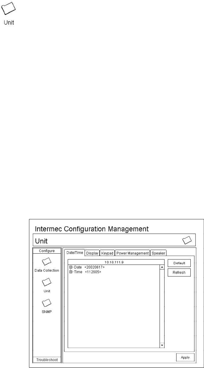
Unit ManagerAppendix —B
352 700 Series Color Mobile Computer User’s Manual
Unit
Within the Unit Manager, click Configuration from the left navigation
bar, then click the Unit icon to access any of these tabs: Date/Time, Dis-
play, Keypad, Power Management, or Speaker.
Date/Time
Sets the current date and time.
Action
Click the Date/Time tab, then select Date or Time and make changes in
the entry field, or tap (+) to expand either the Date or Time parameter,
select the setting to be changed, then select a value from the drop-down
list or enter a new value to change this setting.
SNMP OID
Date: 1.3.6.1.4.1.1963.15.501.2.1.0
Time: 1.3.6.1.4.1.1963.15.501.2.2.0
Options
Date Year 0000`999 (1999)
Month 1-12 (6)
Day 1-31 (1)
Time Hour 0-23 (0)
Minute 0-59 (00)
Second 0-59 (00)
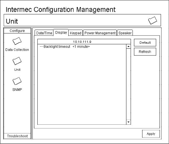
Unit ManagerAppendix —B
353700 Series Color Mobile Computer User’s Manual
Backlight Timeout
Sets the length of time that the display backlight remains on. If you set a
longer timeout value, you use the battery power at a faster rate.
Action
Click the Display tab, then select an option from the Backlight timeout
drop-down list.
SNMP OID
1.3.6.1.4.1.1963.15.13.1.0
Syntax
DFdata
where data is any of the following:
10 10 seconds
30 30 seconds
60 1 minute (default)
120 2 minutes
180 3 minutes
240 4 minutes
300 5 minutes
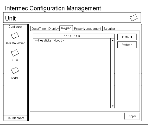
Unit ManagerAppendix —B
354 700 Series Color Mobile Computer User’s Manual
Key Clicks
Enables or disables the keypad clicks. The 700 Series Computer emits a
click each time you press a key or decode a row of a two-dimensional
symbology.
Action
Click the Keypad tab, then select an option from the Key clicks drop-
down list.
SNMP OID
1.3.6.1.4.1.1963.15.12.1.0
Syntax
KCdata
where data is any of the following:
0 Disable clicks
1 Enable soft key clicks
2 Enable loud key clicks (default)
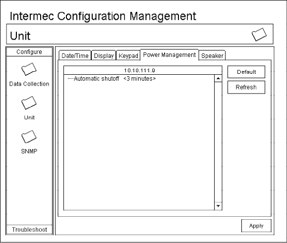
Unit ManagerAppendix —B
355700 Series Color Mobile Computer User’s Manual
Automatic Shutoff
Sets the length of time the 700 Series Computer remains on when there is
no activity. When you turn on the 700 Computer, it either resumes exactly
where it was when you turned it off or boots and restarts your application.
Action
Click the Power Management tab, then select an option from the Auto-
matic shutoff drop-down list.
SNMP OID
1.3.6.1.4.1.1963.15.11.3.0
Syntax
EZdata
where data is any of the following:
1 1 minute
2 2 minutes
3 3 minutes (default)
4 4 minutes
5 5 minutes
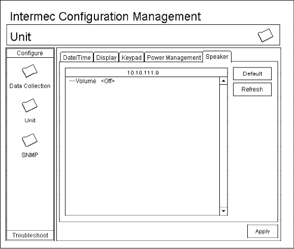
Unit ManagerAppendix —B
356 700 Series Color Mobile Computer User’s Manual
Volume
Changes the volume of all audio signals.
Action
Click the Speaker tab, then select an option from the Volume drop-down
list.
SNMP OID
1.3.6.1.4.1.1963.15.3.1.3.0
Syntax
BVdata
where data is any of the following:
0 Off
1 Very quiet
2 Quiet
3 Normal (default)
4Loud
5 Very loud

Unit ManagerAppendix —B
357700 Series Color Mobile Computer User’s Manual
Using Reader Commands
After the 700 Series Computer is connected to your network, you can send
the 700 Series Computer a reader command from an application to per-
form a task, such as changing the time and date. Some reader commands
temporarily override the configuration settings and some change the con-
figuration settings.
Change Configuration
The Change Configuration command must precede any configuration
command. If you enter a valid string, the 700 Series Computer configura-
tion is modified and the computer emits a high beep. To send the Change
Configuration command through the network, use the $+ [command]
syntax where command is the two-letter command syntax for the configu-
ration command followed by the value to be set for that command.
You can also make changes to several different commands by using the
$+ [command]...[command n] syntax. There are seven configuration
command settings that can be changed in this way. See each command for
information on respective acceptable “data” values.
Command Syntax
Audio Volume BVdata
Automatic Shutoff EZdata
Backlight Timeout DFdata
Key Clicks KCdata
Virtual Wedge Grid AFdata
Virtual Wedge Postamble AEdata
Virtual Wedge Preamble ADdata
Note: See Appendix A, “Control Panel Applets” for more information about
the Virtual Wedge Postamble and Virtual Wedge Preamble commands.
Example 1
To change the Beep Volume to Off, you can send this string to the 700
Series Computer through the network: $+BV0
where:
$+ Indicates Change Configuration.
BV Specifies the Audio Volume parameter.
0Specifies a value of Off.
Example 2
To change the Beep Volume to Very Quiet and the Virtual Wedge Grid to
123: $+BV1AF123
where:
$+ Indicates Change Configuration
BV1 Specifies Audio Volume, set to Very Quiet (1)
AF123 Specifies Virtual Wedge Grid, set to a value of 123.
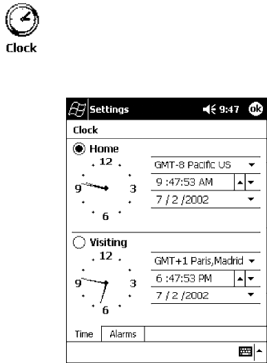
Unit ManagerAppendix —B
358 700 Series Color Mobile Computer User’s Manual
Set Time and Date
This command sets the date and time on the 700 Series Computer. The
default date and time is June 1, 1999 at 12:00 AM.
From the network, send the following:
/+ yyyymmddhhmmss
where acceptable values for the date are:
yyyy 0000-9999 Year
mm 01-12 Month of the year
dd 01-31 Day of the month
hh 00-23 Hour
mm 00-59 Minutes
ss 00-59 Seconds
You can also set the time and date by using Configuration Management in
Unit Manager, or by using the Clock control panel applet in the Settings
menu. To access this control panel applet, tap Start →Settings →the
System tab →the Clock icon to access its control panel applet.

359700 Series Color Mobile Computer User’s Manual
Bar Codes
C
This appendix contains a brief explanation of some of the bar code
symbologies that the 700 Series Color (700C) Mobile Computer decodes
and explains some of the general characteristics and uses of these bar code
types. It also includes several bar code labels that can be scanned into your
700 Series Computer.

Bar CodesAppendix —C
360 700 Series Color Mobile Computer User’s Manual
Bar Code Symbologies
Specific bar code algorithms can be enabled using the setup menus or the
host computer. Once the computer correctly decodes a bar code, the com-
puter encodes data with descriptive information about the symbol. Re-
sponse time is improved by limiting the computer to the bar codes being
used.
Bar Code Data String Formats
Data Bar Code Type Data Format Data Length
UPC short (UPC-E) nddddddc 8
EAN short (EAN-8) fndddddc 8
UPC long (UPC-A) nddddddddddc 12
EAN long (EAN-13) fnddddddddddc 13
UPC short add-on 2 nddddddcaa 10
EAN short add-on 2 fndddddcaa 10
UPC long add-on 2 nddddddddddcaa 14
EAN long add-on 2 fnddddddddddcaa 15
UPC short add-on 5 nddddddcaaaaa 13
EAN short add-on 5 fndddddcaaaaa 13
UPC long add-on 5 nddddddddddcaaaaa 17
EAN long add-on 5 fnddddddddddcaaaaa 18
Interleaved 2 of 5 d......d Scan device dependent
Standard 2 of 5 d......d Scan device dependent
Plessey d......dc Scan device dependent
Codabar sd....ds Scan device dependent
Code 11 d......d Scan device dependent
Code 39 d......d Scan device dependent
Extended Code 39 d......d Scan device dependent
Code 93 d......d Scan device dependent
Code 128 d......d Scan device dependent
Note: These bar code data definitions apply to the Data Format column in
the previous table
a Add-on code digits
c Check digits
d Bar code digits
f EAN flag 1 characters
n Number system digits
s Start and stop digits
If MOD 10 or MOD 11 check digits are enabled, the digit falls at the end
of a bar code data string. Each check digit enabled extends the bar code
data string length by one character.
Bar CodesAppendix —C
361700 Series Color Mobile Computer User’s Manual
The 700 Series Computer recognizes eleven of the most widely used bar
code symbologies. With bar code symbologies, like languages, there are
many different types. A bar code symbology provides the required flexibil-
ity for a particular inventory tracking system.
A symbology may be for particular industries, such as food and beverage,
automotive, railroad, or aircraft. Some of these industries have established
their own bar code symbology because other symbologies did not meet
their needs.
Without going into great detail on the bar code structure, note that no two
products use the same bar code. Each product gets a unique bar code.
Industries that use a particular type of bar code symbology have formed
regulating committees or are members of national institutes that issue and
keep track of bar codes. This ensures that each organization that contrib-
utes to a particular industry conforms to its standard. Without some form
of governing body, bar coding would not work.
SUPC (Universal Product Code) with/without add-ons
SEAN (European Article Numbering Code) with/without add-ons
SCodabar
SC11 (Code 11)
SC39 (Code 39)
SC93 (Code 93)
SC128 (Code 128)
SI 2 of 5 (Interleaved 2 of 5 Code)
SS 2 of 5 (Standard 2 of 5)
SPlessey
SMSI (a variant of Plessey)
Bar CodesAppendix —C
362 700 Series Color Mobile Computer User’s Manual
UPC
The UPC (Universal Product Code) is the symbology used throughout the
grocery and retail industries. This bar code symbology contains two pieces
of numerical information encoded on the bar code, producer identifica-
tion, and product identification information.
The UPC symbol is 12 characters long. The first character of the UPC
symbol is a number system character, such as “0” for grocery items and “3”
for drug- and health-related items.
The UPC symbology is for retail environments such as grocery stores, con-
venience stores, and general merchandise stores.
Some retail items are so small that a standard UPC bar code cannot fit on
the packaging. When this occurs there is a permitted shorter version of the
UPC symbology, referred to as UPC-E. UPC-E is six characters long (eight
including number system and check digit), approximately half the size of a
standard UPC bar code.
EAN
EAN (European Article Numbering) symbology is similar to UPC symbol-
ogy, except that it contains 13 characters and uses the first two to identify
countries.
The EAN symbology is used in the retail environment throughout most of
Europe. Though similar to UPC symbology, these are not interchangeable.
Codabar
Codabar was for retail price-labeling systems. Today it is widely accepted
by libraries, medical industries, and photo finishing services.
Codabar is a discrete, self-checking code with each character represented
by a stand-alone group of four bars and three intervening spaces.
Four different start or stop characters get defined and designated “a”, “b”,
“c”, and “d”. These start and stop characters are constructed using one
wide bar and two wide spaces. A complete Codabar symbol begins with
one of the start or stop characters followed by some number of data char-
acters and ending in one of the start or stop characters.
Any of the start or stop characters may be used on either end of the sym-
bol. It is possible to use the 16 unique start or stop combinations to identi-
fy label type or other information.
Since Codabar is variable-length, discrete, and self-checking, it is a versatile
symbology. The width of space between characters is not critical and may
vary significantly within the same symbol. The character set consists of “0”
through “9”, “-”, “$”, “:”, “/”, “.”, and “+”.
The specific dimensions for bars and spaces in Codabar optimize perfor-
mance of certain early printing and reading equipment. Codabar has 18
different dimensions for bar and space widths. So many different dimen-
sions often result in labels printed out of specification and cause Codabar
printing equipment to be more expensive.

Bar CodesAppendix —C
363700 Series Color Mobile Computer User’s Manual
Code 11
Code 11 satisfies the requirements for a very high density, discrete numeric
bar code. The name Code 11 derives from 11 different data characters that
can be represented, in addition to a start or stop character.
The character set includes the 10 digits and the dash symbol. Each charac-
ter is represented by a stand-alone group of three bars and two intervening
spaces. Although Code 11 is discrete, it is not self-checking. A single print-
ing defect can transpose one character into another valid character. One or
two check digits obtain data security.
The specifications for Code 11 suggest that this code should have a narrow
element width of 7.5 mils. This results in an information density of 15
characters per inch.
Code 39
Code 39 (C39) is the most widely used symbology among the industrial
bar codes. Most major companies, trade associations, and the federal gov-
ernment find this code to fit their needs. The main feature of this symbol-
ogy is the ability to encode messages using the full alphanumeric character
set, seven special characters, and ASCII characters.
Programming for this symbology can be for any length that the application
requires. The application program for the 700 Series Computer handles
symbology at least one character but no more than 32 characters in length.
When programming the computer for Code 39, it is important to set the
symbology limit as close as possible (minimum and maximum bar code
lengths being scanned). Doing so keeps the computer bar code processing
time to a minimum and conserves battery power.
Bar code readers can respond to Uniform Symbology Specification symbols
in non-standard ways for particular applications. These methods are not
for general applications, because of the extra programming required. Code
39 Full ASCII is one example of non-standard code.
Note: See page 368 to scan several Code 39 bar code labels available to
change settings on your 700 Series Computer.
Encoded Code 39 (Concatenation)
If the first data character of a symbol is a space, the reader may be pro-
grammed to append the information contained in the remainder of the
symbol to a storage buffer. This operation continues for all successive sym-
bols that contain a leading space, with messages being added to the end of
previously stored ones. When a message is read which does not contain a
leading space, the contents are appended to the buffer, the entire buffer is
transmitted, and the buffer is cleared.
Encoded Code 39 (Full ASCII)
If the bar code reader is programmed for the task, the entire ASCII charac-
ter set (128 characters) could be coded using two character sequences: a
symbol (“$”,“.”,“%”,“/”) followed by a letter of the alphabet.
Bar CodesAppendix —C
364 700 Series Color Mobile Computer User’s Manual
Code 93
The introduction of Code 93 provided a higher density alphanumeric
symbology designed to supplement Code 39. The set of data characters in
Code 93 is identical with that offered with Code 39. Each character con-
sists of nine modules arranged into three bars and three spaces.
Code 93 uses 48 of the 56 possible combinations. One of these characters,
represented by a square, is reserved for a start or stop character, four are
used for control characters, and the remaining 43 data characters coincide
with the Code 39 character set. An additional single module termination
bar after the stop character concludes the final space.
Code 93 is a variable length, continuous code that is not self-checking. Bar
and spaces widths may be one, two, three, or four modules wide. Its struc-
ture uses edge-to-similar-edge decoding. This makes the bar code immune
to uniform ink spread, which allows liberal bar width tolerances.
Code 93 uses two check characters. Its supporters believes this makes it the
highest density alphanumeric bar code. The dual check digit scheme pro-
vides for high data integrity. All substitution errors in a single character are
detected for any message length.
Code 128
Code 128 (C128) is one of the newest symbologies used by the retail and
manufacturing industries. It responds to the need for a compact alphanu-
meric bar code symbol that could encode complex product identification.
The fundamental requirement called for a symbology capable of being
printed by existing data processing printers (primarily dot-matrix printers)
that produce daily, work-in-progress, job, and product traceability docu-
ments. The ability to print identification messages between 10 and 32
characters long, on existing forms and labels deemed an important require-
ment.
Code 128 uniquely addresses this need as the most compact, complete,
alphanumeric symbology available.
Additionally, the Code 128 design with geometric features, improves scan-
ner read performance, does self-checking, and provides data message man-
agement function codes.
Code 128 encodes the complete set of 128 ASCII characters without ad-
ding extra symbol elements. Code 128 contains a variable-length symbolo-
gy and the ability to link one message to another for composite message
transmission. Code 128, being a double-density field, provides two numer-
ic values in a single character.
Code 128 follows the general bar code format of start zone, data, check
digit, stop code, and quiet zone. An absolute minimum bar or space di-
mension of nine mils (0.010 inch minimum nominal ±0.001 inch toler-
ance) must be maintained.
Characters in Code 128 consist of three bars and three spaces so that the
total character set includes three different start characters and a stop char-
acter.
Bar CodesAppendix —C
365700 Series Color Mobile Computer User’s Manual
UCC/EAN-128 Shipping Container Labeling is a versatile tool that can
ease movement of products and information. The Shipping Container La-
beling bar code can take any form and usually has meaning only within the
company or facility where applied.
Because this random data can get mistaken later for an industry standard
code format, the UCC and EAN chose a symbology uniquely identified
from these other bar codes. This standard is for maximum flexibility, to
handle the diversity of distribution in global markets by cost efficiency.
The UCC/EAN-128 Container Labeling specification calls for a FUNC1
to immediately follow the bar code’ s start character. FUNC1 also follows
any variable-length application field. The specification also calls for the
computer to send “]C1” for the first FUNC1. The specification requires
that the computer send a “<GS>” (hex 1D) for subsequent FUNC1 codes
in the bar code.
Because “<GS>” is not compatible with computer emulation data streams,
the Uniform Code Council has been asked to change the specification.
This change is made to send the same three character sequence “]C1” to
identify the embedded FUNC1 codes.
This implementation should provide for clean application coding by iden-
tifying the same sequences for the same scanned codes. If the communica-
tion of Norand bar code types is enabled, the Shipping Container Label
codes precede with a “J”. These strings will appear on the computer dis-
play. The application may have to allow for strings longer than 48 charac-
ters (maximum length indicated in the specification). Actual length vari-
ance depends on the number of variable-length data fields. Allowing for 60
characters should be sufficient. Within the Code 128 specification, the
computer can link bar codes together. If this is to happen, allow for more
characters (computer limit is 100 characters).
The Application Identifier Standard, that is part of the UCC/EAN Ship-
ping Label concept, complements, rather than replaces, other UCC/EAN
standards. Most UCC/EAN standards primarily identify products.
Several industries expressed the need to standardize more than product
identification. The UCC/EAN Code 128 Application Identifier Standard
supplies this tool. The standard adds versatility for inter-enterprise ex-
changes of perishability dating, lot and batch identification, units of use
measure, location codes, and several other information attributes.
For more detailed information on Code 128 UCC/EAN Shipping Label
bar code and Application Identifier Standard, refer to the UCC/EAN-128
Application Identifier Standard specification.
Bar CodesAppendix —C
366 700 Series Color Mobile Computer User’s Manual
I2of5(Interleaved)
I 2 of 5 (Interleaved 2 of 5 Code) is an all-numeric symbology, widely used
for warehouse and heavy industrial applications. Its use has been particu-
larly prevalent in the automobile industry. The I 2 of 5 symbology can be
placed on smaller labels than what the standard UPC symbology requires.
I 2 of 5 also provides a little more flexibility on the type of material it can
print on. Interleaved 2 of 5 Code has its name because of the way the bar
code is configured.
I 2 of 5 bars and spaces both carry information. The bars represent the
odd number position digits, while spaces represent the even number posi-
tion digits. The two characters are interleaved as one. Messages encoded
with this symbology have to use an even number of characters since two
numeric characters always get interleaved together.
S2of5(Standard2of5)
The code S 2 of 5 (Standard 2 of 5 Code) is designed primarily for:
SWarehouse inventory handling
SIdentification of photo finishing envelopes
SAirline tickets
SBaggage and cargo handling
The code S 2 of 5 is simple and straightforward. All information is con-
tained in the widths of the bars, with the spaces serving only to separate
the individual bars.
Bars can either be wide or narrow, and the wide bars are usually three
times the widths of the narrow bars. Spaces may be any reasonable width
but are typically equal to the narrow bars. Narrow bars are identified as
zero bits and wide bars as one bits.
Remember the code structure by associating the bar positions from left to
right with weighting factors 1, 2, 4, 7, and parity. Exceptions to this rule
are zero, start, and stop. This code is a discrete code, since the white spaces
between the characters are not part of the code. Because the white spaces
carry no information, their dimensions are not critical.
The S 2 of 5 code is self-checking, meaning a scanner passing through a
printing void would detect the proper ratio of wide bars to total bars.
When the scanner spots an error, a non-read will occur.
Bar CodesAppendix —C
367700 Series Color Mobile Computer User’s Manual
Plessey
Plessey finds its origin in the pulse width modulated (PWM) code devel-
oped in England. It is widely used for shelf markings in grocery stores.
Pulse width modulated codes represent each bit of information by a bar
and space pair. A zero bit consists of a narrow bar followed by a wide
space, while a one bit consists of a wide bar followed by a narrow space. It
is mainly a numeric symbology (0-9) with six extra characters available for
assigning any symbol or letter desired.
Plessey codes are not self-checking and employ a variety of check charac-
ters. Plessey employs a polynomial-based Cyclic Redundancy Check
(CRC). For start and stop characters, Plessey employs a 1101 and previous-
ly used a 0101.
This symbology is very limited about what information can be encoded. It
is not considered for new applications.
MSI Code (Variant of Plessey)
In addition to Plessey characteristics, the MSI Code employs a Modulus
10 Check. For start and stop checks, MSI employs a single bit pair of 1 as
a start symbol and a single bit pair of 0 as a stop symbol. MSI reverses the
1-2-4-8 BCD pattern for bit pair weighting to 8-6-2-1.

Bar CodesAppendix —C
368 700 Series Color Mobile Computer User’s Manual
Bar Code Labels
You can change some settings on your 700 Series Computer by scanning
the following Code 39 bar code labels.
SYou can use the Unit Manager application to set the Automatic Shutoff,
Volume, Backlight Timer, or Key Clicks parameters (starting on page
352).
SYou can use the Unit Manager application or the Data Collection con-
trol panel to set the three Virtual Wedge parameters (starting on page
325).
Note: When you use a bar code creation utility to make a scannable bar
code label, the utility probably adds opening and closing asterisks automat-
ically. Asterisks are included here for translation purposes.
Audio Volume
Note: The Audio Volume parameter information is on page 356.
Turn Audio Off
*$+BV0*
*$+BV0*
Set Audio Volume to very quiet
*$+BV1*
*$+VB1*
Set Audio Volume to quiet
*$+BV2*
*$+BV2*
Set Audio Volume to normal (default)
*$+BV3*
*$+BV3*
Set Audio Volume to loud
*$+BV4*
*$+BV4*
Set Audio Volume to very loud
*$+BV5*
*$+BV5*

Bar CodesAppendix —C
369700 Series Color Mobile Computer User’s Manual
Automatic Shutoff
Note: The Automatic Shutoff parameter information is on page 355.
Set Automatic Shutoff to 1 minute
*$+EZ1*
*$+EZ1*
Set Automatic Shutoff to 2 minutes
*$+EZ2*
*$+EZ2*
Set Automatic Shutoff to 3 minutes (default)
*$+EZ3*
*$+EZ3*
Set Automatic Shutoff to 4 minutes
*$+EZ4*
*$+EZ4*
Set Automatic Shutoff to 5 minutes
*$+EZ5*
*$+EZ5*
Backlight Timeout
Note: The Backlight Timeout parameter information is on page 353.
Backlight Timeout 10 seconds
*$+DF10*
*$+DF10*
Backlight Timeout 30 seconds
*$+DF30*
*$+DF30*
Backlight Timeout 1 minute (default)
*$+DF60*
*$+DF60*

Bar CodesAppendix —C
370 700 Series Color Mobile Computer User’s Manual
Backlight Timeout 2 minutes
*$+DF120*
*$+DF120*
Backlight Timeout 3 minutes
*$+DF180*
*$+DF180*
Backlight Timeout 4 minutes
*$+DF240*
*$+DF240*
Backlight Timeout 5 minutes
*$+DF300*
*$+DF300*
Key Clicks
Note: The Key Clicks parameter information is on page 354.
Disable key clicks
*$+KC0*
*$+KC0*
Enable soft key clicks
*$+KC1*
*$+KC1*
Enable loud key clicks (default)
*$+KC2*
*$+KC2*
Bar CodesAppendix —C
371700 Series Color Mobile Computer User’s Manual
Virtual Wedge Grid, Preamble, Postamble
The following parameters are user-configurable strings. Refer to a full
ASCII chart for more information.
Grid
For Virtual Wedge Grid, the first part of the bar code would be the follow-
ing, which can include a string of up to 240 characters. Parameter informa-
tion starts on page 328.
*$+AF
*$+AF
Preamble
For Virtual Wedge Preamble, the first part of the bar code would be below,
followed by a string of up to 31 characters (no <NUL>) and an asterisk.
Default is no characters. Parameter information is on page 326.
*$+AD
*$+AD
Postamble
For Virtual Wedge Postamble, the first part of the bar code would be be-
low, followed by a string of up to 31 characters (no <NUL>) and an aster-
isk. Default is no characters. Parameter information is on page 327.
*$+AE
*$+AE
Bar CodesAppendix —C
372 700 Series Color Mobile Computer User’s Manual

373700 Series Color Mobile Computer User’s Manual
Index
I
The Classes and Functions Index covers classes and functions for the 700 Series
Color Mobile Computer.
The General Index covers all topics. Those in italics are figures, those in bold are
tables.
The Files Index is to assist you in locating descriptions for device drivers, applica-
tions, utilities, batch files, or other files within this publication.
Index
374 700 Series Color Mobile Computer User’s Manual
Classes and Functions
A
add_registry_section, [AddReg]
flags, 244
registry_root_string, 244
value_name, 244
AddReg, [DefaultInstall], 240
[AddReg], add_registry_section
flags, 244
registry_root_string, 244
value_name, 244
AddWep(), 103
AppName, [CEStrings], 237
B
BuildMax, [CEDevice], 238
BuildMin, [CEDevice], 238
C
CancelReadImage, IImage, 226
CancelReadRequest
IADC, 152
IBarCodeReaderControl, 160
[CEDevice]
BuildMax, 238
BuildMin, 238
ProcessorType, 238
UnsupportedPlatforms, 238
VersionMax, 238
VersionMin, 238
CESelfRegister, [DefaultInstall], 240
CESetupDLL, [DefaultInstall], 240
CEShortcuts, [DefaultInstall], 240
[CEShortcuts], shortcut_list_section
shortcut_filename, 245
shortcut_type_flag, 245
target_file/path, 245
target_file_path, 245
CESignature
[SourceDiskNames], 240
[Version], 236
[CEStrings]
AppName, 237
InstallDir, 237
Close, IImage, 228
CloseHandle()
DTR printing, 134, 135
IrDA printing, 128
NPCP printing, 129, 130
ConfigureProfile(), 106
ControlLED, IBarCodeReaderControl, 161
Copyfiles, [DefaultInstall], 240
[CopyFiles], file_list_section
destination_filename, 243
flags, 243
source_filename, 243
create/delete ADC COM objects, 149
CreateEvent(), 283
CreateFile()
DTR printing, 134, 135
IrDA printing, 128
NPCP printing, 129, 130
D
[DefaultInstall]
AddReg, 240
CESelfRegister, 240
CESetupDLL, 240
CEShortcuts, 240
Copyfiles, 240
DeregisterDevice(), 129
DTR printing, 134
[DestinationDirs], file_list_section, 242
DeviceIOControl(), 98
DTR printing, 134
NPCP printing, 129
DeviceIoControl(), NPCP printing, 130, 131
disk_ordinal, [SourceDiskNames], 240
DllRegisterServer, 240
DllUnregisterServer, 240
E
EnableWep(), 105
EncryptWepKeyForRegistry(), 106
F
file_list_section
[CopyFiles]
destination_filename, 243
flags, 243
source_filename, 243
[DestinationDirs], 242
filename, [SourceDiskFiles], 241
G
GetAssociationStatus(), 104
GetAuthenticationMode(), 104
GetBSSID(), 101
GetCodabar, IS9CConfig, 173
GetCode11, IS9CConfig2, 205
GetCode128, IS9CConfig, 180
GetCode39, IS9CConfig, 176, 200
GetCode93, IS9CConfig, 179
GetConfig, ISCP, 217
GetCustomSymIds, IS9CConfig2, 207
GetGlobalAmble, IS9CConfig2, 211
GetI2of5, IS9CConfig, 183
GetLinkSpeed(), 102
GetMac(), 101
GetMatrix2of5, IS9CConfig, 185
GetMSI, IS9CConfig, 187
GetNetworkMode(), 103
GetNetworkType(), 102
GetPDF417, IS9CConfig, 188
GetPDF417Ext, IS9CConfig2, 213
GetPlessey, IS9CConfig, 192
GetPowerMode(), 105
GetRSSI(), 103
GetRTSThreshold(), 106
GetSSID(), 101
Index
375700 Series Color Mobile Computer User’s Manual
GetStandard2of5, IS9CConfig, 194
GetSymIdXmit, IS9CConfig2, 214
GetTelepen, IS9CConfig, 197
GetTXPower(), 102
GetUpcEan, IS9CConfig, 198
GetWepStatus(), 104
I
IADC, 151
CancelReadRequest, 152
Initialize, 153
QueryAttribute, 154
QueryData, 155
Read, 156
SetAttribute, 157
IBARCODEREADER.H, IBarCodeReaderControl func-
tions, 159
IBarCodeReaderControl, 159
CancelReadRequest, 160
ControlLED, 161
Initialize, 162
IssueBeep, 163
QueryAttribute, 164
Read, 165
SetAttribute, 167
TriggerScanner, 171
IImage
CancelReadImage, 226
Close, 228
Open, 227
ReadImage, 225
ReadSigCapBuffer, 221
ReadSigCapFile, 224
Start, 226
Stop, 227
Imager, settings, IS9CConfig3, 216
Initialize
IADC, 153
IBarCodeReaderControl, 162
InstallDir, [CEStrings], 237
IS9CConfig, 172
GetCodabar, 173
GetCode128, 180
GetCode39, 176, 200
GetCode93, 179
GetI2of5, 183
GetMatrix2of5, 185
GetMSI, 187
GetPDF417, 188
GetPlessey, 192
GetStandard2of5, 194
GetTelepen, 197
GetUpcEan, 198
SetCodabar, 174
SetCode128, 181
SetCode39, 177
SetCode93, 179
SetI2of5, 184
SetMatrix2of5, 186
SetMSI, 187
SetPDF417, 189
SetPlessey, 192
SetStandard2of5, 195
SetTelepen, 197
IS9CConfig2, 204
GetCode11, 205
GetCustomSymIds, 207
GetGlobalAmble, 211
GetPDF417Ext, 213
GetSymIdXmit, 214
SetCode11, 205
SetCustomSymIds, 208
SetGlobalAmble, 212
SetPDF417Ext, 213
SetSymIdXmit, 214
IS9CConfig3, 216
ISCP
GetConfig, 217
SetConfig, 218
isOrinoco(), 106
IssueBeep, IBarCodeReaderControl, 163
ITCDeviceClose, 150
ITCDeviceOpen, 140, 149
ITCUUID.LIB, IBarCodeReaderControl functions, 159
K
KernelIoControl(), 264
O
Open, IImage, 227
OSVERSIONINFO.dwBuildNumber, 238
OSVERSIONINFO.dwVersionMajor, 238
OSVERSIONINFO.dwVersionMinor, 238
P
ProcessorType, [CEDevice], 238
Provider, [Version], 236
Q
QueryAttribute
IADC, 154
IBarCodeReaderControl, 164
QueryData, IADC, 155
R
RadioConnect(), 101
RadioDisconnect(), 101
Read, 140
IADC, 156
IBarCodeReaderControl, 165
ReadFile(), NPCP printing, 129
ReadImage, IImage, 225
ReadSigCapBuffer, IImage, 221
ReadSigCapFile, IImage, 224
RegFlushKey(), 81, 262, 270
RegisterDevice(), 129
DTR printing, 134
RegOpenKeyEx(), 282
RegQueryValueEx(), 282
RegSetValueEx(), 282
Index
376 700 Series Color Mobile Computer User’s Manual
S
SetAttribute
IADC, 157
IBarCodeReaderControl, 167
SetAuthenticationMode(), 104
SetChannel(), 105
SetCodabar, IS9CConfig, 174
SetCode11, IS9CConfig2, 205
SetCode128, IS9CConfig, 181
SetCode39, IS9CConfig, 177
SetCode93, IS9CConfig, 179
SetConfig, ISCP, 218
SetCustomSymIds, IS9CConfig2, 208
SetGlobalAmble, IS9CConfig2, 212
SetI2of5, IS9CConfig, 184
SetMatrix2of5, IS9CConfig, 186
SetMSI, IS9CConfig, 187
SetNetworkMode(), 103
SetPDF417, IS9CConfig, 189
SetPDF417Ext, IS9CConfig2, 213
SetPlessey, IS9CConfig, 192
SetRTSThreshold(), 106
SetSSID(), 105
SetStandard2of5, IS9CConfig, 195
SetSymIdXmit, IS9CConfig2, 214
SetTelepen, IS9CConfig, 197
SHFullScreen(), 262, 263
shortcut_list_section, [CEShortcuts]
shortcut_filename, 245
shortcut_type_flag, 245
target_file/path, 245
target_file_path, 245
Signature, [Version], 236
[SourceDiskFiles], filename, 241
[SourceDiskNames]
CESignature, 240
disk_ordinal, 240
SourceDisksNames.MIPS, 241
SourceDisksNames.SH3, 241
Start, IImage, 226
StartScanList(), 107
Stop, IImage, 227
string_key, [Strings], 237
[Strings], string_key, 237
SYSTEMINFO.dwProcessorType, 238
T
Trigger settings, IS9CConfig3, 216
TriggerScanner, IBarCodeReaderControl, 171
U
UnsupportedPlatforms, [CEDevice], 238
V
[Version]
CESignature, 236
Provider, 236
Signature, 236
VersionMax, [CEDevice], 238
VersionMin, [CEDevice], 238
W
WriteFile()
DTR printing, 134, 135
IrDA printing, 128
NPCP printing, 129, 130
Index
377700 Series Color Mobile Computer User’s Manual
General Index
Numbers
1470 Imager. See Imager
1551/1553 Tethered Scanner. See Tethered scanner
1D laser scanner, about, 137
2D Imager
about, 137
data collection features, 146
aimer LED, 146
scaled illumination LED, 146
window size and position, 146
image acquisition features, 147
overview, 146
4820 printer, NPCP driver, 129
6804DM printer
DTR driver, 134
IrDA driver, 128
6804T printer
DTR driver, 134
IrDA driver, 128
6805A printer
DTR driver, 134
IrDA driver, 128
6806 printer
DTR driver, 134
IrDA driver, 128
6808 printer
DTR driver, 134
IrDA driver, 128
printer support, 127
681T printer, DTR driver, 134
6820 printer
IrDA driver, 128
NPCP driver, 129
printer support, 127
6920 Communications Server, ManifestName parameter,
254
700 Platform Build, version number, 342
740 Color Computer, 281
781 printers
DTR driver, 134
printer support, 127
782T printer, printer support, 127
802.11 CR radio CORE module, 107
802.11 WEP Encryption, profile security information, 91
802.11b
antenna color code, 85
API, 100
channel, 89
communications setup, 87
configuration profiles, 100
CORE module, 107
network type, 89
profiles, 87
basic information, 89
certificates, 95
exporting, 96
import/export, 96
importing, 97
read-only, 94
scan list, 97, 98
security information, 90
selected, 97
SSID (network name), 89
WEP encryption, 91
802.1x TLS, profile security information, 92
802.1x TTLS, profile security information, 93
A
Abstract Syntax Notation.1. See ASN.1
ActiveSync
ActiveSync Help, 30
adding programs, 26
adding programs to Start menu, 28
Folder behavior connected to e-mail server, 46
installing applications, 77
Microsoft Reader, 58
Pocket Internet Explorer
favorite links, 62
Mobile Favorites folder, 62
Pocket PC, 29
Pocket PC icon, 13
Pocket PC status icons, 12
URL, 29
ActiveX control tools, unit information control panel, CAB
files, 345
AD command, with/without data, 326
ADC COM interfaces, 138
functions
create/delete objects, 149
IADC, 151
IBarCodeReaderControl, 159
IS9CConfig, 172
IS9CConfig2, 204
IS9CConfig3, 216
Adding a profile, 88
Adding bookmarks, Microsoft Reader, 61
Adding drawings to text, Microsoft Reader, 61
Adding programs
ActiveSync, 26
Pocket Internet Explorer, 27
Pocket PC, 26
to the Start menu, 28
via ActiveSync, 28
via File Explorer, 28
Adjusting settings, Pocket PC, 26
Adobe Acrobat Reader, URL, 116
AE command, with/without data, 327
Aimer LED duration, configuration parameter, 323
Alpha plane on keypad, 281
Annotations index, Microsoft Reader, 61
Antenna, radio type, 85
APIs
802.11b, 100
AT command interface, 115
IrSock, 128
Appointments, via Calendar, 31
Index
378 700 Series Color Mobile Computer User’s Manual
APS linear imager, about, 137
ASCII
printing, 128
printing to a port, port print method, 128
raw text to printer, 128
ASN.1, 125
Asset management, DeviceURL parameter, 253
AT command interface, 115
terminal application, 114
testing, 117
Attaching notes to text, Microsoft Reader, 61
Audio files, Windows Media Player, 57
Audio system
external headset jack, 2
internal microphone, 2
speaker, 2
AutoCab, command line syntax, 82
AutoFTP, 260
AutoIP, 122
Automatic Data Collection. See ADC COM interfaces
Automatic Private IP. See AutoIP
Automatic shutoff
bar code configuration, 369
configuration parameter, 355
Autostart FTP, 260
AvantGo channels, Pocket Internet Explorer, 64
AXCommunication, 345
AXFileTransfer, 345
AXReaderCommand, 345
AXVWedge, 345
B
Backlight timeout
bar code configuration, 369
configuration parameter, 353
Bar Code
scanning labels, 368
supported symbologies, 147, 289
symbologies, 360
Codabar, 362
Code 11, 363
Code 128, 364
Code 39, 363
Code 39 concatenation, 363
Code 39 full ASCII, 363
Code 93, 364
data string formats, 360
EAN, 362
I 2 of 5, 366
MSI code, 367
Plessey, 367
S 2 of 5, 366
UPC, 362
Bar code configuration
audio volume, 368
automatic shutoff, 369
backlight timeout, 369
Code 39, 368
key clicks, 370
BARCODE_DATA_TYPE_ASCII, IBarCodeReaderCon-
trol::Read, 165
BARCODE_DATA_TYPE_UNICODE, IBarCodeReader-
Control::Read, 165
BARCODE_DATA_TYPE_UNKNOWN, IBarCodeRead-
erControl::Read, 165
Battery
low battery conditions, 3
Pocket PC status icons, 12
status, 2
Battery status, unit information control panel applet, 343
Beeper
configuration parameter
frequency, 320
volume, 318
silencing the volume, 319
supported functions, 317
Unit Manager, 349
when not available
beeper frequency, 320
good read beep duration, 322
good read beeps, 321
biActualImageSize, pImgBuffer, IImage::ReadSigCapBuffer,
222
biBitCount, pImgBuffer, IImage::ReadSigCapBuffer, 222
biHeight, pImgBuffer, IImage::ReadSigCapBuffer, 222
biMaxImageBytes, pImgBuffer, IImage::ReadSigCapBuffer,
222
biWidth, pImgBuffer, IImage::ReadSigCapBuffer, 222
Block recognizer, Pocket PC input panel, 17
BlockSize, FTP Server, 252
Bluealps CORE module, 120
Bluetooth
CORE module, 120
unit information control panel, main stack CAB file,
344
Bluetooth compatibility, network support, 120
Bluetooth Device Manager, documentation, 120
Books, Microsoft Reader
adding bookmarks, 61
adding drawings, 61
annotations index, 61
attaching notes, 61
copying, 61
downloading, 58
highlighting, 61
reading, 60
removing, 61
searching, 61
Browing the Internet, Pocket Internet Explorer, 66
BTctrl program, documentation, 120
Build information, 5
byFNC1, IS9CConfig::SetCode128, 181
Index
379700 Series Color Mobile Computer User’s Manual
C
CAB files
after the extraction, 248
creating, 236
INF files, 236
with CAB Wizard, 249
information regarding, 4
installation functions, SETUP.DLL, 248
placing files onto storage card, 80
unit information control panel applet, 344
Cabinet Wizard
creating CAB files, 249
troubleshooting, 250
using the application, 236
Cabling, scanner, 232
Calendar
creating
an appointment, 32
meeting requests, 33
Pocket Outlook, 31
Pocket PC icon, 13
scheduling a meeting, 33
using the summary screen, 33
Capacitor, internal super, 3
Capturing thoughts and ideas, via Notes, 40
Card support
CompactFlash cards, 5
modems, 4
MultiMediaCards, 5
radios, 4
SecureDigital cards, 5
CDMA/1xRTT, 110
antenna color code, 85
AT command set, 116
CORE module, 111
CEImager
location of the executable file, 80
migrating AUTORUN.DAT files, 80
Channel, 802.11 radio module, 89
ClassID field values
VN_CLASS_ASIC, 266
VN_CLASS_BOOTSTRAP, 266
VN_CLASS_KBD, 266
Clock
Pocket PC settings, 26
setting date and time, 358
Closing drivers, NPCP, 130
CMIP, 123
Codabar, 362
configuration parameter, 292
user ID, 310
default S9C settings, 175
enumerations, 175
IS9CConfig::GetCodabar, 173
IS9CConfig::SetCodabar, 174
modifier characters, 219
Code 11, 363
configuration parameter, 306
user ID, 314
default S9C settings, 206
enumerations, 206
IS9CConfig2::GetCode11, 205
IS9CConfig2::SetCode11, 205
modifier characters, 219
Code 128, 364
configuration parameter, 295
FNC1 character, 297
user ID, 310
default S9C settings, 181
enumerations, 182
IImage::ReadSigCapBuffer, 223
IImage::ReadSigCapFile, 224
IS9CConfig::GetCode128, 180
IS9CConfig::SetCode128, 181
modifier characters, 219
Code 39, 363
configuration parameter, 290
user ID, 310
default S9C settings, 177
enumerations, 178
IImage::ReadSigCapBuffer, 223
IImage::ReadSigCapFile, 224
IS9CConfig::GetCode39, 176
IS9CConfig::SetCode39, 177
modifier characters, 219
Code 93, 364
configuration parameter, 294
length, 294
user ID, 311
default S9C settings, 179
enumerations, 180
IS9CConfig::GetCode93, 179
IS9CConfig::SetCode93, 179
modifier characters, 219
Code Division Multiple Access. See CDMA/1xRTT
Codes
11, 363
128, 364
39, 363
39 concatenation, 363
39 full ASCII, 363
93, 364
Cold boot, IOCTL_HAL_COLDBOOT, 275
COM port
configuration, 231
wedge settings, 231
COM1, NPCP parameter, 129
COM1 port, 128
Comm port wedge
disabling, 231
enabling, 230
error messages, 232
limitations, 233
settings, 231
unit information control panel, 344
Command line syntax, AutoCab, 82
Common Object Resource Environment. See CORE
Index
380 700 Series Color Mobile Computer User’s Manual
Communications
DTR, 135
NPCP, 132
Communications options, 83
CompactFlash cards
card support, 5
installing applications, 78
Composing Messages, via Inbox, 45
Computer shutdown, 3
Concatenation, 363
Configuration Management. See Unit Manager
Configuration parameters
aimer LED duration, 323
automatic shutoff, 355
backlight timeout, 353
beeper
frequency, 320
volume, 318
codabar, 292
user ID, 310
code 11, 306
user ID, 314
code 128, 295
FNC1 character, 297
user ID, 310
code 39, 290
user ID, 310
code 93, 294
length, 294
user ID, 311
data matrix, 308
date/time, 352
EAN
13 user ID, 313
8 user ID, 313
good read
beep duration, 322
beeps, 321
identification
contact, 338
location, 340
name, 339
image dimension, 324
interleaved 2 of 5, 303
user ID, 311
key clicks, 354
macro PDF, 300
matrix 2 of 5, 304
user ID, 313
micro PDF 417, 302
MSI, 299
user ID, 311
PDF 417, 300
user ID, 311
plessey, 298
user ID, 312
prefix, 315
QR code, 307
security
encryption key, 335
read encryption, 333
read-only community string, 331
read/write community string, 332
write encryption, 334
SNMP, security subnet mask, 309
standard 2 of 5, 291
user ID, 312
suffix, 316
telepen, 305
user ID, 313
trap
authentication, 336
threshold, 337
UPC
A user ID, 312
E user ID, 312
UPC/EAN, 293
virtual wedge, 325
code page, 329
grid, 328
postamble, 327
preamble, 326
volume, 356
Connecting directly to e-mail server, via Inbox, 42
Connecting to
an ISP, 68
e-mail server, 72
work, 70
Connections
See also Getting connected
directly to e-mail server, 72
ending, 72
setting up an e-mail service, 73
status icon, 12
to an ISP, 68
via Ethernet, 69
via modem, 68
to work, 70
via Ethernet, 71
via modem, 70
via Ethernet
to an ISP, 69
to work, 71
via modem
to an ISP, 68
to work, 70
Contacts
creating a contact, 34
finding a contact, 35
MSN Messenger
chatting with, 55
working with, 54
Pocket Outlook, 34
Pocket PC icon, 13
using the summary screen, 36
Index
381700 Series Color Mobile Computer User’s Manual
Control panel applets
clock, 358
data collection, 288
beeper/LED, 317
imager, 323
symbologies, 289
symbology options, 309
virtual wedge, 325
power, battery status, 2
SNMP, 330
identification, 338
security, 331
traps, 336
system, wireless network, 87
unit information, 341
battery status, 3, 343
CAB files, 344
versions, 6, 342
utilities, 81
Converting writing to text, 20
Copying text, Microsoft Reader, 61
CORE, 84
802.11b radio module, 107
details, 109
general, 107
accessing from
Programs panel, 84
Today screen, 84
Bluealps module, 120
Bluetooth, 120
module for 802.11b NIC, 100
WAN radio module, 111
details, 113
general, 111
Creating
a modem connection
to an ISP, 68
to work, 70
an Ethernet connection
to an ISP, 69
to work, 71
appointment via Calendar, 32
CAB files, 236
with CAB Wizard, 249
contact via Contacts, 34
document via Pocket Word, 47
drawing via Notes, 22
INF files, 236
meeting requests, 33
note via Notes, 41
recording via Notes, 23
task via Tasks, 38
workbook via Pocket Excel, 52
Customer Support, xviii
D
Data collection
2D imager features, 146
ADC COM interfaces, 138
build version number, 342
configuration parameters
aimer LED duration, 323
beeper frequency, 320
beeper volume, 318
codabar, 292
codabar user ID, 310
code 11, 306
code 11 user ID, 314
code 128, 295
code 128 FNC1 character, 297
code 128 user ID, 310
code 39, 290
code 39 user ID, 310
code 93, 294
code 93 length, 294
code 93 user ID, 311
data matrix, 308
EAN-13 user ID, 313
EAN-8 user ID, 313
good read beep duration, 322
good read beeps, 321
image dimension, 324
interleaved 2 of 5, 303
interleaved 2 of 5 user ID, 311
macro PDF, 300
matrix 2 of 5, 304
matrix 2 of 5 user ID, 313
micro PDF 417, 302
MSI, 299
MSI user ID, 311
PDF 417, 300
PDF 417 user ID, 311
plessey, 298
plessey user ID, 312
prefix, 315
QR code, 307
standard 2 of 5, 291
standard 2 of 5 user ID, 312
suffix, 316
telepen, 305
telepen user ID, 313
UPC-E user ID, 312
UPC-A user ID, 312
UPC/EAN, 293
virtual wedge, 325
virtual wedge code page, 329
virtual wedge grid, 328
virtual wedge postamble, 327
virtual wedge preamble, 326
functions
create/delete ADC COM objects, 149
IADC, 151
IBarCodeReaderControl, 159
IS9CConfig, 172
IS9CConfig2, 204
IS9CConfig3, 216
initialization, 138
Unit Manager, 348
Data filtering, virtual wedge grid, 141
Index
382 700 Series Color Mobile Computer User’s Manual
Data Matrix
configuration parameter, 308
IS9CConfig3 function, 216
Date, setting, 358
Date/Time, configuration parameter, 352
Deleting a profile, 88
DeviceName, FTP Server, 253
DeviceURL, FTP Server, 253
DHCP, 122
Display full screen, 263
Docks, modem support, 4
DRAM, low battery shutdown, 3
Drawing mode, Pocket Word, 51
Drawing on the screen
See also Notes
Pocket Word, 51
Drivers
DTR
communications, 135
installing, 134
opening, 135
removing, 134
writing to, 135
NPCP
closing, 130
communications, 132
I/O controls, 131
installing, 129
opening, 130
reading from, 130
removing, 129
writing to, 130
O’ Neil. See DTR printing
DTR printing, 134
closing driver, 135
communications, 135
opening driver, 135
removing driver, 134
writing to driver, 135
dwAttrBufferSize
IBarCodeReaderControl::QueryAttribute, 164
IBarCodeReaderControl::SetAttribute, 169
dwBufferSize
IADC::QueryAttribute, 154
IS9CConfig2::GetGlobalAmble, 211
IS9CConfig2::SetGlobalAmble, 212
dwCommandBuffSize
ISCP::GetConfig, 217
ISCP::SetConfig, 218
dwDataBufferSize
IADC::Read, 156
IBarCodeReaderControl::Read, 165
dwLength
IS9CConfig::SetCode128, 181
IS9CConfig::SetCode39, 177
IS9CConfig::SetCode93, 179
IS9CConfig::SetMatrix2of5, 186
IS9CConfig::SetMSI, 187
IS9CConfig::SetPlessey, 192
dwMaxNumElement, IS9CConfig2::GetCustomSymIds,
207
dwNextMessageSize, IADC::QueryData, 155
dwNumberOfBeeps, IBarCodeReaderControl::IssueBeep,
163
dwNumBytes
IS9CConfig::SetCodabar, 174
IS9CConfig::SetI2of5, 184
IS9CConfig::SetStandard2of5, 195
dwNumElement, IS9CConfig2::SetCustomSymIds, 208
dwReplyBuffMaxSize
ISCP::GetConfig, 217
ISCP::SetConfig, 218
dwStructSize
pImgBuffer, IImage::ReadSigCapBuffer, 222
pSigCapSpec, IImage::ReadSigCapBuffer, 221
dwTimeout
IADC::Read, 156
IBarCodeReaderControl::Read, 166
IImage::ReadImage, 225
dwTotalBufferedBytes, IADC::QueryData, 155
E
E-mail server
getting connected, 72
setting up a service, 73
eAmbleId
IS9CConfig2::GetGlobalAmble, 211
IS9CConfig2::SetGlobalAmble, 212
EAN, 362
configuration parameter, 293
13 user ID, 313
8 user ID, 313
default S9C settings, 181, 201
enumerations, 201
IS9CConfig::GetUpcEan, 198
IS9CConfig::SetUpcEan, 200
modifier characters, 220
ean13Check
IS9CConfig::GetUpcEan, 199
IS9CConfig::SetUpcEan, 200
ean13Select
IS9CConfig::GetUpcEan, 198
IS9CConfig::SetUpcEan, 200
ean8Check
IS9CConfig::GetUpcEan, 199
IS9CConfig::SetUpcEan, 200
ean8Reencode
IS9CConfig::GetUpcEan, 199
IS9CConfig::SetUpcEan, 200
ean8Select
IS9CConfig::GetUpcEan, 198
IS9CConfig::SetUpcEan, 200
eAttr
IBarCodeReaderControl::QueryAttribute, 164
IBarCodeReaderControl::SetAttribute, 167
eAttribID
IADC::QueryAttribute, 154
IADC::SetAttribute, 157
Index
383700 Series Color Mobile Computer User’s Manual
eCheck
IS9CConfig::SetCodabar, 174
IS9CConfig::SetI2of5, 184
IS9CConfig::SetMSI, 187
IS9CConfig::SetPlessey, 192
IS9CConfig::SetStandard2of5, 195
IS9CConfig2::SetCode11, 205
eCip128State, IS9CConfig::SetCode128, 181
eCLSI, IS9CConfig::SetCodabar, 174
eCode128, IS9CConfig2::SetPDF417Ext, 213
eDataType, IBarCodeReaderControl::Read, 165
eDecode
IS9CConfig::SetCodabar, 174
IS9CConfig::SetCode128, 181
IS9CConfig::SetCode39, 177
IS9CConfig::SetCode93, 179
IS9CConfig::SetI2of5, 184
IS9CConfig::SetMatrix2of5, 186
IS9CConfig::SetMSI, 187
IS9CConfig::SetPlessey, 192
IS9CConfig::SetStandard2of5, 195
IS9CConfig::SetTelepen, 197
IS9CConfig2::SetCode11, 205
IS9CConfig2::SetPDF417Ext, 213
eDepth, pSigCapSpec, IImage::ReadSigCapBuffer, 222
eDeviceFlags
IADC::Initialize, 153
IBarCodeReaderControl::Initialize, 162
ITCDeviceOpen, 149
Editing a profile, 88
Edition information, 8
eEan128Ident, IS9CConfig::SetCode128, 181
eFormat
IImage::ReadImage, 225
IS9CConfig::SetCode39, 177
IS9CConfig::SetStandard2of5, 195
IS9CConfig::SetTelepen, 197
pImgBuffer, IImage::ReadSigCapBuffer, 222
pSigCapSpec, IImage::ReadSigCapBuffer, 222
eLED, IBarCodeReaderControl::ControlLED, 161
eLengthId
IS9CConfig::SetCodabar, 174
IS9CConfig::SetI2of5, 184
IS9CConfig::SetStandard2of5, 195
eMacroPdf, IS9CConfig::SetPDF417, 189
Embedded modules, SB555, 110
Encoded Code 39
concatenation, 363
full ASCII, 363
Ending a connection, 72
Enumerations
Codabar, 175
Code 11, 206
Code 128, 182
Code 39, 178
Code 93, 180
Interleaved 2 of 5, 185
Matrix 2 of 5, 186
MSI, 188
PDF 417, 190
Plessey, 193
Standard 2 of 5, 196
Telepen, 198
UPC/EAN, 201
ePdf417Decode, IS9CConfig::SetPDF417, 189
ePdfAddressee, IS9CConfig::SetPDF417, 189
ePdfChecksum, IS9CConfig::SetPDF417, 189
ePdfControlHeader, IS9CConfig::SetPDF417, 189
ePdfFileName, IS9CConfig::SetPDF417, 189
ePdfFileSize, IS9CConfig::SetPDF417, 189
ePdfSegmentCount, IS9CConfig::SetPDF417, 189
ePdfSender, IS9CConfig::SetPDF417, 189
ePdfTimeStamp, IS9CConfig::SetPDF417, 189
Epson Escape Sequences, 128
Error messages
comm port wedge, 232
tethered scanner, 232
ERROR_INSUFFICIENT_BUFFER
IOCTL_HAL_ITC_READ_PARM, 265
IOCTL_HAL_ITC_WRITE_SYSPARM, 270
ERROR_INVALID_PARAMETER
IOCTL_HAL_ITC_READ_PARM, 265
IOCTL_HAL_ITC_WRITE_SYSPARM, 270
eSS
IS9CConfig::SetCodabar, 174
IS9CConfig::SetCode39, 177
eSSChars, IS9CConfig::SetCode39, 177
eSymbology, IBarCodeReaderControl::Read, 165
eSymIdXmit, IS9CConfig2::SetSymIdXmit, 214
Ethernet
communications setup, 86
creating a connection
to an ISP, 69
to work, 71
ETSI GSM 07.05 interface specifications, 115
ETSI GSM 07.07 interface specifications, 115
European Article Numbering code. See EAN
eVer, IS9CConfig2::SetCode11, 205
Excel. See Pocket Excel
Exporting a profile, 802.11 radio module, 96
F
Factory repair, xviii
Favorite links, Pocket Internet Explorer, 62
File Explorer
adding programs to Start menu, 28
Pocket PC, 25
removing programs, 28
File Transfer Protocol. See FTP
Filter expression values, virtual wedge grid, 142
Find feature, Pocket PC, 25
fLedOn, IBarCodeReaderControl::ControlLED, 161
FlushBufferedData
IADC::CancelReadRequest, 152
IBarCodeReaderControl::CancelReadRequest, 160
Folder behavior connected to e-mail server
ActiveSync, 46
IMAP4, 46
POP3, 46
SMS, 46
Index
384 700 Series Color Mobile Computer User’s Manual
FRAME_NOT_ACKED, 131
fScannerOn, IBarCodeReaderControl::TriggerScanner, 171
fSigCapEnable, IImage::Open, 227
FTP
client, 256
configurable parameters, 252
BlockSize, 252
DeviceName, 253
DeviceURL, 253
IDNATarget, 254
ManifestName, 254
PauseAtStartup, 255
Root, 255
FTPDCMDS subdirectory, 259
heartbeat, 256
RTC 959, 259
server, 256
installing applications, 78
server requests
CDUP, 256
CWD, 256
DELE, 256
HELP, 256
LIST, 256
MKD, 256
MODE, 256
NLST, 256
NOOP, 256
PASS, 256
PWD, 256
QUIT, 256
RETR, 256
RMD, 256
RNFR, 256
RNTO, 257
SITE, 257
SITE ATTRIB, 257
SITE BOOT, 258
SITE COPY, 258
SITE EXIT, 258
SITE HELP, 258
SITE KILL, 258
SITE LOG, 258
SITE PLIST, 258
SITE RUN, 258
SITE STATUS, 259
SITE TIMEOUT, 259
STOR, 257
SYST, 257
TYPE, 257
USER, 257
XCUP, 257
XCWD, 257
XMKD, 257
XPWD, 257
XRMD, 257
stopping server from application, 260
support, 256
web browsers, 259
FTPDCMDS subdirectory, FTP support, 259
Full screen display, 263
G
GDI approach, 128
General Packet Radio Service. See GSM/GPRS
Getting connected
directly to an e-mail server, 72
infrared (IR) port, 67
ISP, 67
Pocket PC, 67
setting up an e-mail service, 73
to an ISP, 68
creating a modem connection, 68
creating an Ethernet connection, 69
to work, 70
creating a modem connection, 70
creating an Ethernet connection, 71
transfer items using infrared, 67
Global services and support center, xviii
Gold plane on keypad, 281
Good read, configuration parameter
beep duration, 322
beeps, 321
Grid data
configuration parameter, 328
filtering, 141
GSM/GPRS, 110
antenna color code, 85
AT command set
GEM350X, 116
MC45, 116
CORE module, 111
H
HAL, verion of Pocket PC
IOCTL_HAL_GET_BOOTLOADER_VERINFO,
274
IOCTL_HAL_GET_OAL_VERINFO, 273
Header files
IADC.H, IADC functions, 151
IBARCODEREADER.H, IBarCodeReaderControl
functions, 159
IS9CCONFIG.H
IS9CConfig functions, 172
IS9CConfig2 functions, 204
ITCDEVMGMT.H, 149
Headset jack, external, 2
Highlighting text, Microsoft Reader, 61
Hotmail account, 53
I
I2of5.See Interleaved 2 of 5
I/O controls, NPCP driver, 131
iAspectRatio, pSigCapSpec, IImage::ReadSigCapBuffer,
221
Index
385700 Series Color Mobile Computer User’s Manual
ID field values
IOCTL_HAL_ITC_READ_PARM
ITC_NVPARM_80211_INSTALLED, 268
ITC_NVPARM_80211_RADIOTYPE, 268
ITC_NVPARM_ANTENNA_DIVERSITY, 267
ITC_NVPARM_BLUETOOTH_INSTALLED, 268
ITC_NVPARM_CONTRAST, 266
ITC_NVPARM_DISPLAY_TYPE, 266
ITC_NVPARM_ECN, 266
ITC_NVPARM_EDBG_SUBNET, 266
ITC_NVPARM_EDG_IP, 266
ITC_NVPARM_ETHERNET_ID, 265
ITC_NVPARM_INTERMEC_DATACOLLEC-
TION_HW, 267
ITC_NVPARM_INTERMEC_DATACOLLEC-
TION_SW, 267
ITC_NVPARM_INTERMEC_SOFTWARE_CON-
TENT, 267
ITC_NVPARM_LAN9000_INSTALLED, 269
ITC_NVPARM_MANF_DATE, 265
ITC_NVPARM_MCODE, 266
ITC_NVPARM_RTC_RESTORE, 267
ITC_NVPARM_SERIAL_NUM, 265
ITC_NVPARM_SERIAL2_INSTALLED, 269
ITC_NVPARM_SERVICE_DATE, 266
ITC_NVPARM_SIM_PRO-
TECT_HW_INSTALLED, 269
ITC_NVPARM_SIM_PRO-
TECT_SW_INSTALLED, 269
ITC_NVPARM_VERSION_NUMBER, 266
ITC_NVPARM_VIBRATE_INSTALLED, 269
ITC_NVPARM_WAN_FREQUENCY, 268
ITC_NVPARM_WAN_INSTALLED, 268
ITC_NVPARM_WAN_RADIOTYPE, 268
ITC_NVPARM_WAN_RI, 267
IOCTL_HAL_ITC_WRITE_SYSPARM
ITC_ DOCK_SWITCH, 270
ITC_ WAKEUP_MASK, 271
ITC_AMBIENT_FRONTLIGHT, 271
ITC_AMBIENT_KEYBOARD, 271
ITC_REGISTRY_LOCATION, 270
ITC_REGISTRY_SAVE_ENABLE, 270
Identification
configuration parameter
contact, 338
location, 340
name, 339
Unit Manager, 351
IDNA
DeviceName, 253
DeviceURL, 253
IDNATarget, 254
ManifestName, 254
IDNATarget, FTP Server, 254
iid, ITCDeviceOpen, 149
IImage interface, 221
Image, acquisition features, 147
Image dimension, configuration parameter, 324
Imager
beeper functions not available
beeper frequency, 320
good read beep duration, 322
good read beeps, 321
control panel appet, data collection, 323
data collection parameters
aimer LED duration, 323
data matrix, 308
image dimension, 324
QR code, 307
settings, 232
supported
beeper functions, 317
functions, 323
symbologies, 289
supported symbologies, 147
symbologies not available
CIP 128 French Pharmaceutical, 296
Code 11, 306
Code 128 FNC1 character, 297
EAN 128 ]C1, 296
Macro PDF, 300
Matrix 2 of 5, 304
Micro PDF 417, 302
Telepen, 305
symbology user IDs not available
Codabar, 310
Code 11, 314
Code 128, 310
Code 39, 310
Code 93, 311
EAN 13, 313
EAN 8, 313
Interleaved 2 of 5, 311
Matrix 2 of 5, 313
MSI, 311
PDF 417, 311
Plessey, 312
Standard 2 of 5, 312
Telepen, 313
UPC A, 312
UPC E, 312
Unit Manager, 350
IMAP4, Folder behavior connected to e-mail server, 46
Import libraries
ITCDEVMGMT.LIB, 149
ITCUUID.LIB
IADC functions, 151
IBarCodeReaderControl functions, 159
IS9CConfig functions, 172
IS9CConfig2 functions, 204
Importing a profile, 802.11 radio module, 97
Index
386 700 Series Color Mobile Computer User’s Manual
Inbox
composing messages, 45
connecting directly to e-mail server, 42
Folder behavior connected to e-mail server, 46
getting connected, 67
managing e-mail messages and folders, 46
Pocket Outlook, 42
Pocket PC icon, 13
synchronizing e-mail messages, 42
using a message list, 43
using My Text, 24
INF files, creating, 236
Infrared (IR) port
Pocket PC, 67
transfer items using, 67
receiving information, 67
sending information, 67
Input panel
block recognizer, 17
keyboard, 17
letter recognizer, 18
methods available, 16
Pocket PC, 14
Pocket Word, 49
selecting typed text, 18
transcriber, 18
word suggestions, 17
Installation, site, xviii
Installation functions, SETUP.DLL, 248
Installing applications
using a storage card, 78
using CompactFlash cards, 78
using SecureDigital cards, 79
with ActiveSync, 77
with Application Manager, 78
with FTP Server, 78
Installing drivers
DTR, 134
NPCP, 129
Instant messaging, 53
Pocket PC icon, 12
Intelliget Bar Code Unit
IImage::ReadSigCapBuffer, 223
IImage::ReadSigCapFile, 224
Interface specifications, ETSI GSM 07.0x, 115
Interleaved 2 of 5, 366
configuration parameter, 303
user ID, 311
default S9C settings, 184
enumerations, 185
IS9CConfig::GetI2of5, 183
IS9CConfig::SetI2of5, 184
modifier characters, 219
Intermec Device Network Announcement. See IDNA
Internet Explorer. See Pocket Internet Explorer
Internet explorer
Pocket PC 2002 edition, 8
software build version, 5
Internet Service Provider. See ISP
IOCTL_GET_CPU_ID, 280
IOCTL_HAL_COLDBOOT, 275, 280
IOCTL_HAL_GET_BOOT_DEVICE, 277
IOCTL_HAL_GET_BOOTLOADER_VERINFO, 274
IOCTL_HAL_GET_DEVICE_INFO, 264
IOCTL_HAL_GET_DEVICEID, 272
IOCTL_HAL_GET_OAL_VERINFO, 273
IOCTL_HAL_GET_RESET_INFO, 276
IOCTL_HAL_ITC_READ_PARM, 265
IOCTL_HAL_ITC_WRITE_SYSPARM, 270
IOCTL_HAL_REBOOT, 278, 280
IOCTL_HAL_WARMBOOT, 275, 280
IOCTL_LOAD_NDIS_MINIPORT, 98
IOCTL_NPCP_BIND, 131
IOCTL_NPCP_CANCEL, 131
IOCTL_NPCP_CLOSE, 131
IOCTL_NPCP_ERROR, 131
IOCTL_NPCP_FLUSH, 131
IOCTL_PROCESSOR_INFORMATION, 279
IOCTL_UNLOAD_NDIS_MINIPORT, 98
iOffsetX, pSigCapSpec, IImage::ReadSigCapBuffer, 221
iOffsetY, pSigCapSpec, IImage::ReadSigCapBuffer, 222
IrDA printing, 128
iResolution, pSigCapSpec, IImage::ReadSigCapBuffer, 222
IS9CConfig3
Data Matrix symbology, 216
imager settings, 216
QRCode symbology, 216
trigger settings, 216
ISP
connecting to via Pocket PC, 68
creating
a modem connection, 68
an Ethernet connection, 69
Pocket Internet Explorer, 62
Pocket PC, 67
ITC_ DOCK_SWITCH, 270
ITC_ WAKEUP_MASK, 271
ITC_AMBIENT_FRONTLIGHT, 271
ITC_AMBIENT_KEYBOARD, 271
ITC_BARCODE_LASER_GOOD_READ_LED, IBar-
CodeReaderControl::ControlLED, 161
ITC_DEVID_80211RADIO_INTEL_2011B, 268
ITC_DEVID_80211RADIO_MAX values
ITC_DEVID_80211RADIO_INTEL_2011B, 268
ITC_DEVID_80211RADIO_NONE, 268
ITC_DEVID_80211RADIO_NONE, 268
ITC_DEVID_INTERMEC2D_IMAGER, 267
ITC_DEVID_OEM2D_IMAGER, 267
ITC_DEVID_SCANHW_MAX values
ITC_DEVID_INTERMEC2D_IMAGER, 267
ITC_DEVID_OEM2D_IMAGER, 267
ITC_DEVID_SCANHW_NONE, 267
ITC_DEVID_SE900_LASER, 267
ITC_DEVID_SE900HS_LASER, 267
ITC_DEVID_SCANHW_NONE, 267
ITC_DEVID_SE900_LASER, 267
ITC_DEVID_SE900HS_LASER, 267
ITC_DEVID_WANRADIO_NONE, 268
ITC_DEVID_WANRADIO_SIEMENS_MC45, 268
ITC_DEVID_WANRADIO_SIERRA_SB555, 268
Index
387700 Series Color Mobile Computer User’s Manual
ITC_DEVID_WANRADIO_XIRCOM_GEM3503, 268
ITC_DHATTR_READFILTER
IADC::SetAttribute, rgbData, 157
IBarCodeReaderControl::SetAttribute, 167
ITC_DHDEVFLAG_NODATA, ITCDeviceOpen, 149
ITC_DHDEVFLAG_READAHEAD
IADC::Initialize, 153
IBarCodeReaderControl::Initialize, 162
ITCDeviceOpen, 149
ITC_FILE_OPEN_E, IImage::ReadSigCapFile, 224
ITC_IFTP_STOP, 260
ITC_IMGBUFF_TOO_SMALL_E
IImage::ReadImage, 225
IImage::ReadSigCapBuffer, 223
ITC_INV_PARAMETER_E
IImage::ReadImage, 225
IImage::ReadSigCapBuffer, 223
IImage::ReadSigCapFile, 224
ITC_KEYBOARD_CHANGE, CreateEvent(), 283
ITC_MAXFILTER_CHARS, IBarCodeReaderControl::Se-
tAttribute, 167
ITC_MULTICLIENT_ENABLE, IADC::SetAttribute
eAttribID, 157
rgbData, 157
ITC_NVPARM_80211_INSTALLED, 268
ITC_NVPARM_80211_RADIOTYPE, 268
ITC_NVPARM_ANTENNA_DIVERSITY, 267
ITC_NVPARM_BLUETOOTH_INSTALLED, 268
ITC_NVPARM_CONTRAST, 266
ITC_NVPARM_DISPLAY_TYPE, 266
ITC_NVPARM_ECN, 266
ITC_NVPARM_EDBG_SUBNET, 266
ITC_NVPARM_EDG_IP, 266
ITC_NVPARM_ETHERNET_ID, 265
ITC_NVPARM_INTERMEC_DATACOLLEC-
TION_HW, 267
ITC_NVPARM_INTERMEC_DATACOLLEC-
TION_SW, 267
ITC_NVPARM_INTERMEC_SOFTWARE_CON-
TENT, 267
ITC_NVPARM_LAN9000_INSTALLED, 269
ITC_NVPARM_MANF_DATE, 265
ITC_NVPARM_MCODE, 266
ITC_NVPARM_RTC_RESTORE, 267
ITC_NVPARM_SERIAL_NUM, 265
ITC_NVPARM_SERIAL2_INSTALLED, 269
ITC_NVPARM_SERVICE_DATE, 266
ITC_NVPARM_SIM_PROTECT_HW_INSTALLED,
269
ITC_NVPARM_SIM_PROTECT_SW_INSTALLED,
269
ITC_NVPARM_VERSION_NUMBER, 266
ITC_NVPARM_VIBRATE_INSTALLED, 269
ITC_NVPARM_WAN_FREQUENCY, 268
ITC_NVPARM_WAN_INSTALLED, 268
ITC_NVPARM_WAN_RADIOTYPE, 268
ITC_NVPARM_WAN_RI, 267
ITC_RDRATTR_GOOD_READ_BEEP_DURATION,
IBarCodeReaderControl::SetAttribute, 167
ITC_RDRATTR_GOOD_READ_BEEPS_NUMBER,
IBarCodeReaderControl::SetAttribute, 167
ITC_RDRATTR_GOOD_READ_LED_ENABLE, IBar-
CodeReaderControl::SetAttribute, 167
ITC_RDRATTR_SCANNER_ENABLE, IBarCodeRead-
erControl::SetAttribute, 167
ITC_RDRATTR_TONE_ENABLE, IBarCodeReader-
Control::SetAttribute, 167
ITC_RDRATTR_TONE_FREQUENCY, IBarCodeRead-
erControl::SetAttribute, 167
ITC_RDRATTR_VOLUME_LEVEL, IBarCodeReader-
Control::SetAttribute, 167
ITC_REGISTRY_LOCATION, 270
ITC_REGISTRY_SAVE_ENABLE, 270
ITC_RESULT_ERR_BADREGION_E
IImage::ReadSigCapBuffer, 223
IImage::ReadSigCapFile, 224
ITC_RESULT_NO_BC_DECODED_E
IImage::ReadSigCapBuffer, 223
IImage::ReadSigCapFile, 224
ITC_TIMEOUT_E, IImage::ReadImage, 225
ITU-T interface specifications, 115
K
Keeping a to-do list, via Tasks, 37
KernelIoControl
IOCTL_GET_CPU_ID, 280
IOCTL_HAL_COLDBOOT, 275, 280
IOCTL_HAL_GET_BOOT_DEVICE, 277
IOCTL_HAL_GET_BOOTLOADER_VERINFO,
274
IOCTL_HAL_GET_DEVICE_INFO, 264
IOCTL_HAL_GET_DEVICEID, 272
IOCTL_HAL_GET_OAL_VERINFO, 273
IOCTL_HAL_GET_RESET_INFO, 276
IOCTL_HAL_ITC_READ_PARM, 265
IOCTL_HAL_ITC_WRITE_SYSPARM, 270
IOCTL_HAL_REBOOT, 278, 280
IOCTL_HAL_WARMBOOT, 275, 280
IOCTL_PROCESSOR_INFORMATION, 279
Key clicks
bar code configuration, 370
configuration parameter, 354
Keyboard, Pocket PC input panel, 17
Keypad
advanced remapping, 283
change notification, 283
driver registry settings, 282
planes, 281
remapping, 281
sample registry keys, 284
Knowledge Central, xviii
Index
388 700 Series Color Mobile Computer User’s Manual
L
Laser scanner
configuration parameters, 286
data collection parameters
beeper frequency, 320
beeper volume, 318
codabar, 292
codabar user ID, 310
code 11, 306
code 11 user ID, 314
code 128, 295
code 128 FNC1 character, 297
code 128 user ID, 310
code 39, 290
code 39 user ID, 310
code 93, 294
code 93 length, 294
code 93 user ID, 311
EAN-13 user ID, 313
EAN-8 user ID, 313
good read beep duration, 322
good read beeps, 321
interleaved 2 of 5, 303
interleaved 2 of 5 user ID, 311
macro PDF, 300
matrix 2 of 5, 304
matrix 2 of 5 user ID, 313
micro PDF 417, 302
MSI, 299
MSI user ID, 311
PDF 417, 300
PDF 417 user ID, 311
plessey, 298
plessey user ID, 312
prefix, 315
standard 2 of 5, 291
standard 2 of 5 user ID, 312
suffix, 316
telepen, 305
telepen user ID, 313
UPC-E user ID, 312
UPC-A user ID, 312
UPC/EAN, 293
virtual wedge, 325
virtual wedge code page, 329
virtual wedge grid, 328
virtual wedge postamble, 327
virtual wedge preamble, 326
SNMP configuration parameters
identification contact, 338
identification location, 340
identification name, 339
security encryption key, 335
security read encryption, 333
security read-only community string, 331
security read/write community string, 332
security subnet mask, 309
security write encryption, 334
trap authentication, 336
trap threshold, 337
supported
beeper functions, 317
symbologies, 289
supported symbologies, 147
symbologies not available
data matrix, 308
Datamatrix, 307
LEAP, 802.1x profile, security information, 93
Letter recognizer, Pocket PC input panel, 18
Library, Microsoft Reader, 59
Line printing, 128
lpBytesReturned
IOCTL_GET_CPU_ID, 280
IOCTL_HAL_GET_BOOT_DEVICE, 277
IOCTL_HAL_GET_BOOTLOADER_VERINFO,
274
IOCTL_HAL_GET_DEVICE_INFO, 264
IOCTL_HAL_GET_DEVICEID, 272
IOCTL_HAL_GET_OAL_VERINFO, 273
IOCTL_HAL_GET_RESET_INFO, 276
IOCTL_HAL_ITC_READ_PARM, 265
IOCTL_HAL_ITC_WRITE_SYSPARM, 270
IOCTL_PROCESSOR_INFORMATION, 279
lpInBuf
IOCTL_GET_CPU_ID, 280
IOCTL_HAL_COLDBOOT, 275
IOCTL_HAL_GET_BOOT_DEVICE, 277
IOCTL_HAL_GET_BOOTLOADER_VERINFO,
274
IOCTL_HAL_GET_DEVICE_INFO, 264
IOCTL_HAL_GET_DEVICEID, 272
IOCTL_HAL_GET_OAL_VERINFO, 273
IOCTL_HAL_GET_RESET_INFO, 276
IOCTL_HAL_ITC_READ_PARM, 265
IOCTL_HAL_ITC_WRITE_SYSPARM, 270
IOCTL_HAL_REBOOT, 278
IOCTL_HAL_WARMBOOT, 275
IOCTL_PROCESSOR_INFORMATION, 279
lpInBufSize
IOCTL_GET_CPU_ID, 280
IOCTL_HAL_COLDBOOT, 275
IOCTL_HAL_GET_BOOT_DEVICE, 277
IOCTL_HAL_GET_BOOTLOADER_VERINFO,
274
IOCTL_HAL_GET_DEVICE_INFO, 264
IOCTL_HAL_GET_DEVICEID, 272
IOCTL_HAL_GET_OAL_VERINFO, 273
IOCTL_HAL_GET_RESET_INFO, 276
IOCTL_HAL_REBOOT, 278
IOCTL_HAL_WARMBOOT, 275
IOCTL_PROCESSOR_INFORMATION, 279
Index
389700 Series Color Mobile Computer User’s Manual
lpOutBuf
IOCTL_GET_CPU_ID, 280
IOCTL_HAL_COLDBOOT, 275
IOCTL_HAL_GET_BOOT_DEVICE, 277
IOCTL_HAL_GET_BOOTLOADER_VERINFO,
274
IOCTL_HAL_GET_DEVICE_INFO, 264
IOCTL_HAL_GET_DEVICEID, 272
IOCTL_HAL_GET_OAL_VERINFO, 273
IOCTL_HAL_GET_RESET_INFO, 276
IOCTL_HAL_ITC_READ_PARM, 265
IOCTL_HAL_ITC_WRITE_SYSPARM, 270
IOCTL_HAL_REBOOT, 278
IOCTL_HAL_WARMBOOT, 275
IOCTL_PROCESSOR_INFORMATION, 279
LPT9 printer device, 129
M
Macro PDF, configuration parameter, 300
Managing e-mail messages and folders, via Inbox, 46
ManifestName, FTP Server, 254
Matrix 2 of 5
configuration parameter, 304
user ID, 313
default S9C settings, 186
enumerations, 186
IS9CConfig::GetMatrix2of5, 185
IS9CConfig::SetMatrix2of5, 186
modifier characters, 219
Meetings, via Calendar, 31
Menus, Pocket PC settings, 26
MIBs
ASN.1, 125
files, 125
object identifier, 126
OIDs, 126
Micro PDF 417, configuration parameter, 302
Microphone, internal, 2
Microsoft Developer Network Library. See MSDN library
Microsoft Exchange e-mail account, 53
Microsoft Passport account, 53
Microsoft Reader
books
downloading, 58
reading, 60
removing, 61
features, 61
adding bookmarks, 61
adding drawings, 61
annotations index, 61
attaching notes, 61
copying text, 61
highlighting text, 61
searching for text, 61
Pocket PC, 58
using the library, 59
Microsoft Word. See Pocket Word
Migrating applications, 80
Mini-Landline modems, 4
Mobile Favorites folder, Pocket Internet Explorer, 62
Modems
card support, 4
creating a connection
to an ISP, 68
to work, 70
MP3 files, Windows Media Player, 57
MSDN library, 260
MSI, 367
configuration parameter, 299
user ID, 311
default S9C settings, 187
enumerations, 188
IS9CConfig::GetMSI, 187
IS9CConfig::SetMSI, 187
modifier characters, 219
MSN account, 53
MSN Messenger
about, 53
accounts
Hotmail, 53
Microsoft Exchange e-mail, 53
Microsoft Passport, 53
MSN, 53
contacts
chatting with, 55
working with, 54
Pocket PC icon, 13
setting up, 54
using My Text, 24
MultiMediaCards, card support, 5
N
nBufferSize, IADC::SetAttribute, 157
nDepth, IImage::ReadImage, 225
NDIS_NET_AUTO_UNKNOWN, GetNetworkMode(),
103
NDIS_NET_MODE_ESS, GetNetworkMode(), 103
NDIS_NET_MODE_IBSS, GetNetworkMode(), 103
NDIS_NET_MODE_UNKNOWN, GetNetworkMode(),
103
NDIS_NET_TYPE_DS, GetNetworkType(), 102
NDIS_NET_TYPE_FH, GetNetworkType(), 102
NDIS_NET_TYPE_UNDEFINED, GetNetworkType(),
102
NDIS_POWER_LEVEL_1, GetTXPower(), 102
NDIS_POWER_LEVEL_15, GetTXPower(), 102
NDIS_POWER_LEVEL_30, GetTXPower(), 102
NDIS_POWER_LEVEL_5, GetTXPower(), 102
NDIS_POWER_LEVEL_63, GetTXPower(), 102
NDIS_POWER_LEVEL_UNKNOWN, GetTXPower(),
102
NDIS_RADIO_ASSOCIATED, GetAssocationStatus(),
104
NDIS_RADIO_AUTH_MODE_AUTO, GetAuthentica-
tionMode(), 104
NDIS_RADIO_AUTH_MODE_ERROR, GetAuthentic-
ationMode(), 104
NDIS_RADIO_AUTH_MODE_OPEN, GetAuthentica-
tionMode(), 104
Index
390 700 Series Color Mobile Computer User’s Manual
NDIS_RADIO_AUTH_MODE_SHARED, GetAuthen-
ticationMode(), 104
NDIS_RADIO_POWER_MODE_CAM, GetPower-
Mode(), 105
NDIS_RADIO_POWER_MODE_MAX, GetPower-
Mode(), 105
NDIS_RADIO_POWER_MODE_PSP, GetPowerMode(),
105
NDIS_RADIO_POWER_UNKNOWN, GetPower-
Mode(), 105
NDIS_RADIO_SCANNING, GetAssociationStatus(), 104
NDIS_RADIO_WEP_ABSENT, GetWepStatus, 104
NDIS_RADIO_WEP_DISABLED, GetWepStatus(), 104
NDIS_RADIO_WEP_ENABLED, GetWepStatus(), 104
NDIS_RADIO_WEP_NOT_SUPPORTED, GetWepSta-
tus(), 104
Network adapters
802.11b, 87
antenna color code, 85
Ethernet communications, 86
wireless printing, 120
WWAN radio options, 110
Network management. See SNMP
Network type, 802.11 radio module, 89
nFilterChars
IADC::SetAttribute, 157
IBarCodeReaderControl::SetAttribute, 167
nInBufSize
IOCTL_HAL_ITC_READ_PARM, 265
IOCTL_HAL_ITC_WRITE_SYSPARM, 270
Notes
creating a note, 41
drawing on the screen, 22
creating a drawing, 22
selecting a drawing, 22
Pocket Outlook, 40
Pocket PC icon, 13
recording a message, 23
creating a recording, 23
writing on the screen, 19
alternate writing, 21
converting writing to text, 20
selecting the writing, 19
tips for good recognition, 21
nOutBufSize
IOCTL_GET_CPU_ID, 280
IOCTL_HAL_COLDBOOT, 275
IOCTL_HAL_GET_BOOT_DEVICE, 277
IOCTL_HAL_GET_BOOTLOADER_VERINFO,
274
IOCTL_HAL_GET_DEVICE_INFO, 264
IOCTL_HAL_GET_DEVICEID, 272
IOCTL_HAL_GET_OAL_VERINFO, 273
IOCTL_HAL_GET_RESET_INFO, 276
IOCTL_HAL_ITC_READ_PARM, 265
IOCTL_HAL_ITC_WRITE_SYSPARM, 270
IOCTL_HAL_REBOOT, 278
IOCTL_HAL_WARMBOOT, 275
IOCTL_PROCESSOR_INFORMATION, 279
NPCP printing, 129
about, 129
closing driver, 130
COM1 parameters, 129
communications, 132
driver I/O controls, 131
installation, 129
LPT9, 129
opening driver, 130
reading from driver, 130
removal, 129
sample code, 132
unit information control panel, NPCPTEST CAB file,
344
writing to driver, 130
O
O’ Neil printing
See also DTR printer
installing driver, 134
Object store
IOCTL_HAL_COLDBOOT, 275
IOCTL_HAL_REBOOT, 278
IOCTL_HAL_WARMBOOT, 275
Oldstyle device ID, 272
Onsite repair, xviii
Opening drivers
DTR, 135
NPCP, 130
Operators, virtual wedge grid, 144
Other publications, xviii
Owner information, Pocket PC settings, 26
P
Page format printing, 128
Password
Pocket Excel, 53
Pocket PC settings, 26
PauseAtStartup, FTP Server, 255
pBarCodeDataDetails, IBarCodeReaderControl::Read, 165
pbyFNC1, IS9CConfig::GetCode128, 180
PDF 417
about the laser scanner, 137
configuration parameter, 300
user ID, 311
default S9C settings, 190
enumerations, 190
extensions
IS9CConfig2::GetPDF417ext, 213
IS9CConfig2::SetPDF417ext, 213
IImage::ReadSigCapBuffer, 223
IImage::ReadSigCapFile, 224
IS9CConfig::GetPDF417, 188
IS9CConfig::SetPDF417, 189
modifier characters, 220
pdwBufferSize, IS9CConfig2::GetGlobalAmble, 211
Index
391700 Series Color Mobile Computer User’s Manual
pdwLength
IS9CConfig::GetCode128, 180
IS9CConfig::GetCode93, 179
IS9CConfig::GetMatrix2of5, 185
IS9CConfig::GetMSI, 187
IS9CConfig::GetPlessey, 192
pdwNumBytes
IS9CConfig::GetCodabar, 173
IS9CConfig::GetI2of5, 183
IS9CConfig::GetStandard2of5, 194
pdwNumElement, IS9CConfig2::GetCustomSymIds, 207
pdwReplyBuffSize
ISCP::GetConfig, 217
ISCP::SetConfig, 218
pdwTotalDiscardedBytes, IADC::CancelReadRequest, 152
peCheck
IS9CConfig::GetCodabar, 173
IS9CConfig::GetCode39, 176
IS9CConfig::GetI2of5, 183
IS9CConfig::GetMSI, 187
IS9CConfig::GetPlessey, 192
IS9CConfig::GetStandard2of5, 194
IS9CConfig2::GetCode11, 205
peCip128State, IS9CConfig::GetCode128, 180
peCLSI, IS9CConfig::GetCodabar, 173
peCode128, IS9CConfig2::GetPDF417Ext, 213
peDecode
IS9CConfig::GetCodabar, 173
IS9CConfig::GetCode128, 180
IS9CConfig::GetCode39, 176
IS9CConfig::GetCode93, 179
IS9CConfig::GetI2of5, 183
IS9CConfig::GetMatrix2of5, 185
IS9CConfig::GetMSI, 187
IS9CConfig::GetPlessey, 192
IS9CConfig::GetStandard2of5, 194
IS9CConfig::GetTelepen, 197
IS9CConfig2::GetCode11, 205
IS9CConfig2::GetPDF417Ext, 213
peEan128Ident, IS9CConfig::GetCode128, 180
peFormat
IS9CConfig::GetCode39, 176
IS9CConfig::GetStandard2of5, 194
IS9CConfig::GetTelepen, 197
peLengthId
IS9CConfig::GetCodabar, 173
IS9CConfig::GetI2of5, 183
IS9CConfig::GetStandard2of5, 194
peMacroPdf, IS9CConfig::GetPDF417, 188
pePdf417Decode, IS9CConfig::GetPDF417, 188
pePdfAddressee, IS9CConfig::GetPDF417, 189
pePdfChecksum, IS9CConfig::GetPDF417, 189
pePdfControlHeader, IS9CConfig::GetPDF417, 188
pePdfFileName, IS9CConfig::GetPDF417, 188
pePdfFileSize, IS9CConfig::GetPDF417, 189
pePdfSegmentCount, IS9CConfig::GetPDF417, 188
pePdfSender, IS9CConfig::GetPDF417, 189
pePdfTimeStamp, IS9CConfig::GetPDF417, 188
peSS
IS9CConfig::GetCodabar, 173
IS9CConfig::GetCode39, 176
peSSChars, IS9CConfig::GetCode39, 176
peSymIdXmit, IS9CConfig2::GetSymIdXmit, 214
peVer, IS9CConfig2::GetCode11, 205
pImgBuffer
IImage::ReadImage, 225
IImage::ReadSigCapBuffer, 222
Planes, keypad, 281
Plessey, 367
configuration parameter, 298
user ID, 312
default S9C settings, 193
enumerations, 193
IS9CConfig::GetPlessey, 192
IS9CConfig::SetPlessey, 192
modifier characters, 220
pnBufferData, IADC::QueryAttribute, 154
pnBytesReturned
IADC::Read, 156
IBarCodeReaderControl::Read, 165
Pocket Excel
about, 52
creating a workbook, 52
Pocket PC icon, 13
Pocket Internet Explorer
about, 62
adding programs, 27
AvantGo channels, 64
browing the Internet, 66
favorite links, 62
getting connected, 67
Mobile Favorites folder, 62
Pocket PC icon, 13
software build, 5
viewing mobile favorites and channels, 66
Pocket Outlook, 31
Calendar, 31
Index
392 700 Series Color Mobile Computer User’s Manual
Pocket PC
about, 8
ActiveSync, 29
basic skills, 11
Calendar, 31
command bar, 14
Contacts, 34
edition information, 8
getting connected, 67
Inbox, 42
input panel. See Input panel
IOCTL_HAL_GET_BOOTLOADER_VERINFO,
274
IOCTL_HAL_GET_OAL_VERINFO, 273
MSN Messenger, 53
navigation bar, 14
Notes, 40
notifications, 15
status icon, 12
Pocket Excel, 52
Pocket Word, 47
pop-up menus, 15
programs, 13
status icons, 12
support URLs, 10
Tasks, 37
Today screen, 11
where to find information, 10
Windows Media Player, 57
writing on the screen, 19
Pocket Word
about, 47
creating a document, 47
drawing mode, 51
Pocket PC icon, 13
recording mode, 51
tips, 53
typing mode, 49
writing mode, 50
POP3, Folder behavior connected to e-mail server, 46
Postamble
configuration parameter, 327
with/without data, 327
Power
control panel, battery status, 2
Pocket PC settings, 26
ppvObject
ITCDeviceClose, 150
ITCDeviceOpen, 149
Preamble
configuration parameter, 326
with/without data, 326
Prefix, configuration parameter, user ID, 315
Printer support, 128
IrDA printer driver, 128
NPCP printer driver, 129
O’ Neil printer driver, 134
Processor information, IOCTL_PROCESSOR_IN-
FORMATION, 279
Profiles
802.11 radio module, 87
basic information, 89
certificates, 95
import/export, 96
read-only, 94
scan list, 97
security information, 90
adding to unit, 88
deleting, 88
editing, 88
Programs, adding or removing, Pocket PC, 26
pSigCapSpec
IImage::ReadSigCapBuffer, 221
IImage::ReadSigCapFile, 224
pStructSymIdPair
IS9CConfig2::GetCustomSymIds, 207
IS9CConfig2::SetCustomSymIds, 208
pSystemTime, IADC::Read, 156
pszDevice, ITCDeviceOpen, 149
pszDeviceName
IADC::Initialize, 153
IBarCodeReaderControl::Initialize, 162
pszFileName, IImage::ReadSigCapFile, 224
pwLength, IS9CConfig::GetCode39, 176
pwTotalDiscardedBytes, IBarCodeReaderControl::Cancel-
ReadRequest, 160
pwTotalDiscardedMessages
IADC::CancelReadRequest, 152
IBarCodeReaderControl::CancelReadRequest, 160
Q
QR code
configuration parameter, 307
IS9CConfig3 function, 216
Quick Response code. See QR code
R
Radios
See also Network adapters
card support, 4
Reader commands, 357
configuration change, 357
date and time settings, 358
Reading from drivers, NPCP, 130
Reboot methods
IOCTL_HAL_COLDBOOT, 280
IOCTL_HAL_REBOOT, 280
IOCTL_HAL_WARMBOOT, 280
Record button, recording a message, 23
Recording a message
See also Notes
Pocket Word, 51
Recording mode, Pocket Word, 51
Index
393700 Series Color Mobile Computer User’s Manual
Recovery CD
AutoCab method, 82
AutoRun system, 76
AUTOUSER.DAT file, 81
part numbers, xviii
RegFlushKey() API, 262
S9C upgrade, 345
updating the system software, 79
RegFlush utility, 81
Registry
FTP Server parameters, 252
keypad remapping, 282
sample view of key mapping, 284
save location, IOCTL_HAL_ITC_WRITE_SYSPARM,
270
writing to a storage card, 81
Registry settings
AutoCfg, 122
AutoFTP, 261
AutoInterval, 122
AutoIP/DHCP, 122
DhcpMaxRetry, 122
DhcpRetryDialogue, 122
EnableDHCP, 122
keypad driver, 282
keypad planes
alpha, 282
gold, 282
unshifted, 282
Related publications, xviii
Removeable card support, 5
Removing drivers
DTR, 134
NPCP, 129
Removing programs, Pocket PC, 26, 28
RFC 959, 259
rgbAttrBuffer
IBarCodeReaderControl::QueryAttribute, 164
IBarCodeReaderControl::SetAttribute, 168
rgbBuffer
IADC::QueryAttribute, 154
IS9CConfig2::GetGlobalAmble, 211
IS9CConfig2::SetGlobalAmble, 212
rgbCommandBuff
ISCP::GetConfig, 217
ISCP::SetConfig, 218
rgbData, IADC::SetAttribute, 157
rgbDataBuffer
IADC::Read, 156
IBarCodeReaderControl::Read, 165
rgBeepRequests, IBarCodeReaderControl::IssueBeep, 163
rgbImageData, pImgBuffer, IImage::ReadSigCapBuffer,
222
rgbLengthBuff
IS9CConfig::GetCodabar, 173
IS9CConfig::GetI2of5, 183
IS9CConfig::GetStandard2of5, 194
IS9CConfig::SetCodabar, 174
IS9CConfig::SetI2of5, 184
IS9CConfig::SetStandard2of5, 195
rgbReplyBuff
ISCP::GetConfig, 217
ISCP::SetConfig, 218
Root, FTP Server, 255
S
S2of5.See Standard 2 of 5
S_DEVICE_CONTENTION_E, IImage::Open, 227
S_DEVICE_NOT_OPENED_E
IImage::CancelReadImage, 226
IImage::Close, 228
IImage::ReadImage, 225
IImage::ReadSigCapBuffer, 223
IImage::ReadSigCapFile, 224
IImage::Start, 226
IImage::Stop, 227
S_IMG_NOT_PRESENT_E
IImage::Open, 227
IImage::Stop, 227
S_OK
IImage::CancelReadImage, 226
IImage::Close, 228
IImage::Open, 227
IImage::ReadImage, 225
IImage::ReadSigCapBuffer, 223
IImage::ReadSigCapFile, 224
IImage::Start, 226
IImage::Stop, 227
S9C
initialization, 138
IS9CConfig functions, 172
IS9CConfig2 functions, 204
IS9CConfig3 functions, 216
unit information control panel, upgrade files, 345
version number, 342
Sabre 1551E or 1553
See also Tethered scanner
cabling, 232
settings, 232
Sample code, NPCP printing, 132
SB555 radio, 110
Scan list of profiles, 802.11 radio module, 98
Scanner, unit configuration parameters
automatic shutoff, 355
backlight timeout, 353
date/time, 352
key clicks, 354
volume, 356
Scanner cabling, 232
Scheduling appointments and meetings, via Calendar, 31
SDK, unit information control panel, 345
SDMMC Disk, 80
Searching for text, Microsoft Reader, 61
SecureDigital cards
card support, 5
installing applications, 78, 79
Index
394 700 Series Color Mobile Computer User’s Manual
Security
configuration parameter
encryption key, 335
read encryption, 333
read-only community string, 331
read/write community string, 332
subnet mask, 309
write encryption, 334
Unit Manager, 350
Selected profile, 802.11 radio module, 97
Selecting, drawing via Notes, 22
Sending and receiving messages, via Inbox, 42
Serial port, modem support, 4
Service contract status, xviii
Setting date and time, 358
Setting up an e-mail service, 73
SETUP.DLL, installation functions, 248
Signature capture
IImage interface, 221
IImage::CancelReadImage, 226
IImage::Close, 228
IImage::Open, 227
IImage::ReadImage, 225
IImage::ReadSigCapBuffer, 221
IImage::ReadSigCapFile, 224
IImage::Start, 226
IImage::Stop, 227
Simple Network Management Protocol. See SNMP
Site installations, xviii
Site surveys, xviii
SMS, Folder behavior connected to e-mail server, 46
SNMP, 125
about SNMP, 123
CMIP, 123
configuration parameters
identification contact, 338
identification location, 340
identification name, 339
security encryption key, 335
security read encryption, 333
security read-only community string, 331
security read/write community string, 332
security subnet mask, 309
security write encryption, 334
trap authentication, 336
trap threshold, 337
control primitives, 123
multiple retrievals, 124
retrieval, 124
Unit Manager, 350
using the protocol, 123
SNMP OIDs
aimer LED duration, 323
automatic shutoff, 355
backlight timeout, 353
beeper
frequency, 320
volume, 318
codabar, 292
user ID, 310
code 11, 306
user ID, 314
code 128, 295
FNC1 character, 297
user ID, 310
code 39, 290
user ID, 310
code 93, 294
length, 294
user ID, 311
data matrix, 308
date/time, 352
default S9C settings, 210
EAN
13 user ID, 313
8 user ID, 313
good read
beep duration, 322
beeps, 321
identification
contact, 338
location, 340
name, 339
image dimension, 324
interleaved 2 of 5, 303
user ID, 311
IS9CConfig2::GetCustomSymIds, 207
IS9CConfig2::GetSymIdXmit, 214
IS9CConfig2::SetCustomSymIds, 208
IS9CConfig2::SetSymIdXmit, 214
key clicks, 354
macro PDF, 300
matrix 2 of 5, 304
user ID, 313
micro PDF 417, 302
MSI, 299
user ID, 311
PDF 417, 300
user ID, 311
plessey, 298
user ID, 312
prefix, 315
QR code, 307
security
encryption key, 335
read encryption, 333
read-only community string, 331
read/write community string, 332
write encryption, 334
security subnet mask, 309
standard 2 of 5, 291
user ID, 312
suffix, 316
telepen, 305
user ID, 313
transmission option, 215
trap
authentication, 336
threshold, 337
Index
395700 Series Color Mobile Computer User’s Manual
UPC
A user ID, 312
E user ID, 312
UPC/EAN, 293
virtual wedge, 325
code page, 329
grid, 328
postamble, 327
preamble, 326
volume, 356
Symbology ID defaults, 219
Software Developer’ s Kit. See SDK
Software Tools CD. See Tools CD
Software versions, 6, 342
700 Series Computer, 5
unit information control panel applet, 342, 344
Speaker, 2
SSID (network name), 802.11 radio module, 89
Standard 2 of 5, 366
configuration parameter, 291
user ID, 312
default S9C settings, 196
enumerations, 196
IS9CConfig::GetStandard2of5, 194
IS9CConfig::SetStandard2of5, 195
modifier characters, 220
Start Menu, adding programs, 28
via ActiveSync, 28
via File Explorer, 28
Status icons, Pocket PC, 12
Stream device driver
NPCPPORT.DLL, 129
ONEIL.DLL, 134
stTimeStamp, IBarCodeReaderControl::Read, 165
Suffix, configuration parameter, 316
Summary screen
Calendar, 33
Contacts, 36
Tasks, 39
Support
global services and support center, xviii
web, xviii
Symbologies, 360
scanning labels, 368
Unit Manager, 348
user IDs
Codabar, 310
Code 11, 314
Code 128, 310
Code 39, 310
Code 93, 311
EAN 13, 313
EAN 8, 313
Interleaved 2 of 5, 311
Matrix 2 of 5, 313
MSI, 311
PDF 417, 311
Plessey, 312
Standard 2 of 5, 312
Telepen, 313
UPC A, 312
UPC E, 312
when not available
imager, 298, 299, 300, 302, 304, 305, 306
laser scanner, 307, 308
Symbology ID, Unit Manager, 349
Synchronizing e-mail messages, via Inbox, 42
System status maintained, 4
szDest, EncryptWepKeyForRegistry(), 106
szFilter
IADC::SetAttribute, 157
IBarCodeReaderControl::SetAttribute, 167
szSource, EncrypWepKeyForRegistry(), 106
T
Tas k s
creating a task, 38
Pocket Outlook, 37
Pocket PC icon, 13
using the summary screen, 39
TCP/IP client, DHCP server, 122
Technical support, xviii
Tel e p e n
configuration parameter, 305
user ID, 313
default S9C settings, 197
enumerations, 198
IS9CConfig::GetTelepen, 197
IS9CConfig::SetTelepen, 197
modifier characters, 220
Telephone numbers, xviii
Testing AT commands, 117
Tethered scanner
capabilities, 233
disabling, 231
enabling, 231
error messages, 232
limitations, 233
settings, 231
Text messages, Pocket PC, 24
Time, setting, 358
Tips for working, Pocket Excel, 53
TLS, 802.1x profile, 92
Today, Pocket PC settings, 26
Today screen, Pocket PC, 11
Tools CD
base operating system files, 78
Bluetooth documentation, 120
CAB files, 4, 78, 344
CE Imager, 80
Comm Port Wedge CAB file, 344
management tools installed on desktop, 77
MIB files, 125
part number, xviii
sample NPCP code, 132
SRDEVMGMT.CAB file, 286
Unit Manager CAB file, 347
Wireless Printing Development Guide, 120
wireless printing sample, 345
wireless printing SDK, 120
Index
396 700 Series Color Mobile Computer User’s Manual
Tracking people, via Contacts, 34
Transcriber, Pocket PC input panel, 18
Transfer items using infrared
getting connected, 67
receiving information, 67
sending information, 67
Trap configuration parameters
authentication, 336
threshold, 337
Tra p s
control panel appet, SNMP, 336
Unit Manager, 351
Troubleshooting, CAB Wizard, 250
TTLS, 802.1x profile, 93
Typing mode, Pocket Word, 49
Typing on the screen, Pocket Word, 49
U
UDP
FTPDCE, 256
within SNMP, 123
UDP broadcasts, IDNATarget parameter, 254
uiHeight, pSigCapSpec, IImage::ReadSigCapBuffer, 222
uiWidth, pSigCapSpec, IImage::ReadSigCapBuffer, 222
Unit, configuration parameters
automatic shutoff, 355
backlight timeout, 353
date/time, 352
key clicks, 354
volume, 356
Unit information
battery status, 343
CAB files, 344
ActiveX control tools, 345
Bluetooth stack, 344
Comm Port Wedge, 344
NPCP printer, 344
S9C Upgrade, 345
SDK, 345
Unit Manager, 345
Unit Manager help, 345
Windows configuration, 345
wireless printing demo, 345
wireless printing sample, 345
versions, 6, 342
700 Platform Build, 342
DataCollection Build, 342
S9C, 342
Unit Manager
automatic shutoff, 355
backlight timeout, 353
data collection, 348
beeper/LED, 349
imager, 350
symbologies, 348
symbology ID, 349
virtual wedge, 350
date/time, 352
documentation, 347
key clicks, 354
reader commands, 357
changing configuration, 357
setting time and date, 358
SNMP, 350
identification, 351
security, 350
traps, 351
volume, 356
Unit manager
installing applications, 78
unit information control panel, 345
help files, 345
Universal Product Code. See UPC
Unshifted plane on keypad, 281
UPC, 362
configuration parameter, 293
A user ID, 312
E user ID, 312
default S9C settings, 201
enumerations, 201
IS9CConfig::GetUpcEan, 198
IS9CConfig::SetUpcEan, 200
modifier characters, 220
upcACheck
IS9CConfig::GetUpcEan, 199
IS9CConfig::SetUpcEan, 200
upcAddOn2
IS9CConfig::GetUpcEan, 198
IS9CConfig::SetUpcEan, 200
upcAddOn5
IS9CConfig::GetUpcEan, 198
IS9CConfig::SetUpcEan, 200
upcAddOnDigits
IS9CConfig::GetUpcEan, 198
IS9CConfig::SetUpcEan, 200
upcANumSystem
IS9CConfig::GetUpcEan, 199
IS9CConfig::SetUpcEan, 200
upcAReencode
IS9CConfig::GetUpcEan, 199
IS9CConfig::SetUpcEan, 200
upcASelect
IS9CConfig::GetUpcEan, 198
IS9CConfig::SetUpcEan, 200
upceanDecode
IS9CConfig::GetUpcEan, 198
IS9CConfig::SetUpcEan, 200
upcECheck
IS9CConfig::GetUpcEan, 199
IS9CConfig::SetUpcEan, 200
upcENumSystem
IS9CConfig::GetUpcEan, 199
IS9CConfig::SetUpcEan, 200
upcEReencode
IS9CConfig::GetUpcEan, 199
IS9CConfig::SetUpcEan, 200
upcESelect
IS9CConfig::GetUpcEan, 198
IS9CConfig::SetUpcEan, 200
Updating, bootloader, 77
Index
397700 Series Color Mobile Computer User’s Manual
URLs
ActiveSync, 29
Adobe Acrobat Reader, 116
AT command interface
CDMA/1xRTT SB555, 116
GPRS/GSM GEM350X, 116
GPRS/GSM MC45, 116
customer support, xviii
full screen display, 263
Knowledge Central, xviii
MIBs, 125
Microsoft Exchange e-mail account, 53
Microsoft Passport account, 53
Microsoft support, 10
MSDN library, 260
Pocket PC, 10
Pocket PC support, 10
web support, xviii
User Datagram Protocol. See UDP
Using a message list, via Inbox, 43
UUID, 272
V
Video files, Windows Media Player, 57
Viewing mobile favorites and channels, Pocket Internet
Explorer, 66
Virtual wedge
bar code configuration
grid, 371
postamble, 371
preamble, 371
configuration parameter, 325
code page, 329
grid, 328
postamble, 327
preamble, 326
data filtering, 141
filter expression values, 142
global amble
IS9CConfig2::GetGlobalAmble, 211
IS9CConfig2::SetGlobalAmble, 212
operators, 144
Unit Manager, 350
VN_CLASS_ASIC, 266
VN_CLASS_BOOTSTRAP, 266
VN_CLASS_KBD, 266
Volum e
bar code configuration, 368
configuration parameter, 356
W
WAN radio CORE module, 111
WAN radio IDs
ITC_DEVID_WANRADIO_NONE, 268
ITC_DEVID_WANRADIO_SIEMENS_MC45, 268
ITC_DEVID_WANRADIO_SIERRA_SB555, 268
WAN rado CORE module
phone application, 115
terminal application, 114
WAP pages, 62
connecting to an ISP, 68
Warm boot
IOCTL_HAL_REBOOT, 278
IOCTL_HAL_WARMBOOT, 275
Web addresses. See URLs
Web browsers, FTP support, 259
Web pages, 62
connecting to an ISP, 68
Web support, xviii
Welch Allyn 1470 Imager
cabling, 232
settings, 232
WEP encryption, 802.11 radio module, 91
Windows configuration, unit information control panel,
WinCfg CAB file, 345
Windows Media files, Windows Media Player, 57
Windows Media Player, Pocket PC, 57
Wireless Application Protocol. See WAP pages
Wireless network, 87
Wireless printing
Bluetooth compatible module, 120
unit information control panel
PDWPM0C CAB file, 345
WP_SAMPLE.CAB file, 345
Wireless TCP/IP installations, BlockSize parameter, 252
Wireless WAN
AT command interface
CDMA/1xRTT SB555, 116
GPRS/GSM GEM350X, 116
GPRS/GSM MC45, 116
CDMA/1xRTT, 110
GEM350x, 110
GSM/GPRS, 110
SB555, 110
testing AT commands, 117
wNumberOfMessages, IADC::QueryData, 155
Word documents. See Pocket Word
Work
creating
a modem connection, 70
an Ethernet connection, 71
getting connected, 70
Writing mode, Pocket Word, 50
Writing on the screen
See also Notes
Pocket Word, 50
Writing to drivers
DTR, 135
NPCP, 130
wStructSize, IBarCodeReaderControl::Read, 165
WWAN. See Wireless WAN
X
Xscale processor ID, IOCTL_GET_CPU_ID, 280
Index
398 700 Series Color Mobile Computer User’s Manual
Files Index
Numbers
80211API.DLL, 100
80211CONF.EXE, 100
80211SCAN.EXE, 100
A
AUTOUSER.DAT, 79
C
CABWIZ.DDF, 249
CABWIZ.EXE, 236, 249
CEIMAGER.EXE, 80
CPL802.CPL, 100
D
DEVICEID.H, 272
E
EXITME.BIN, 259
F
FTPDCE.EXE, 256, 259
AutoFTP, 261
FTP Server, 251
FTPDCE.TXT, 259
I
IADC.H, IADC functions, 151
IADCDEVICE.H
IADC::SetAttribute, 157
IBarCodeReaderControl::SetAttribute, 167
INTERMEC.MIB, 125
IS9CCONFIG.H
IS9CConfig functions, 172
IS9CConfig2 functions, 204
ITCADC.MIB, 125
ITCDEVMGMT.H, 149
ITCDEVMGMT.LIB, 149
ITCSNMP.MIB, 125
ITCTERMINAL.MIB, 125
ITCUUID.LIB
IADC functions, 151
IS9CConfig functions, 172
IS9CConfig2 functions, 204
M
MAKECAB.EXE, 249
MOD80211.DLL, 100
N
NETWLAN.DLL, 100
NPCPPORT.DLL, 129
NRINET.INI, 345
O
OEMIOCTL.H
IOCTL_GET_CPU_ID, 280
IOCTL_HAL_COLDBOOT, 275
IOCTL_HAL_GET_BOOT_DEVICE, 277
IOCTL_HAL_GET_BOOTLOADER_VERINFO,
274
IOCTL_HAL_GET_OAL_VERINFO, 273
IOCTL_HAL_GET_RESET_INFO, 276
IOCTL_HAL_ITC_READ_PARM, 265
IOCTL_HAL_ITC_WRITE_SYSPARM, 270
IOCTL_HAL_REBOOT, 278
IOCTL_HAL_WARMBOOT, 275
ONEIL.DLL, 134
P
PKFUNCS.H
IOCTL_HAL_GET_DEVICEID, 272
IOCTL_PROCESSOR_INFORMATION, 279
R
REBOOTME.BIN, 259
__RESETMEPLEASE__.T XT, 248
RPM.EXE, 241
RPMCE212.INI, 241
S
SETUP.DLL, 240, 248
DllMain, 248
SRDEVMGMT.CAB, 286
T
TAHOMA.TTF, 241
W
WCESTART.INI, 241

Corporate Headquarters
6001 36th Avenue West
Everett, Washington 98203
tel 425.348.2600
fax 425.355.9551
www.intermec.com
700 Series Color Mobile Computer User’s Manual - November 2002
*961054031*
*961054031* REV B