Intermec Technologies SB555 SB555 Radio in 700C User Manual back let85x11
Intermec Technologies Corporation SB555 Radio in 700C back let85x11
Contents
- 1. 700C User Manual part 2
- 2. 700C Regulatory Manual Supplement
- 3. 700C User Manual part 1
- 4. Item 5 from FCC email Feb 07 2003
- 5. User Manual
Item 5 from FCC email Feb 07 2003
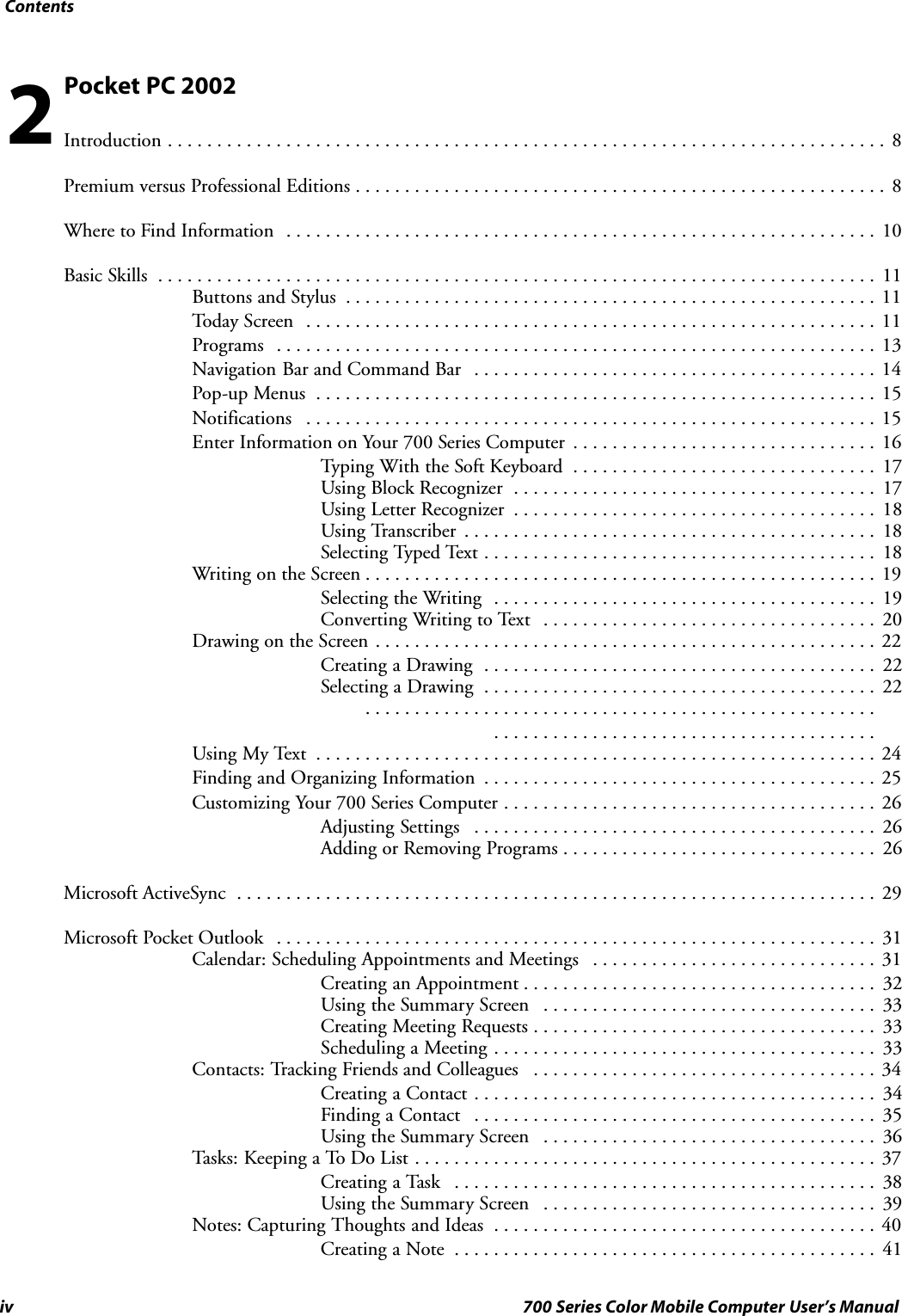
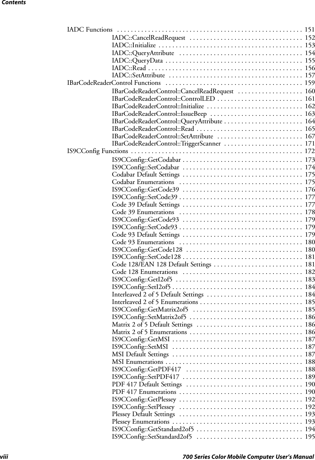

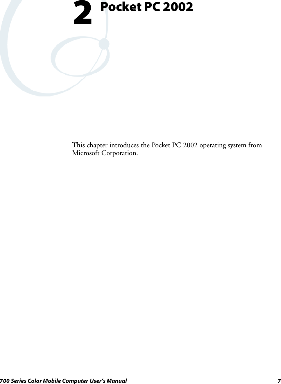
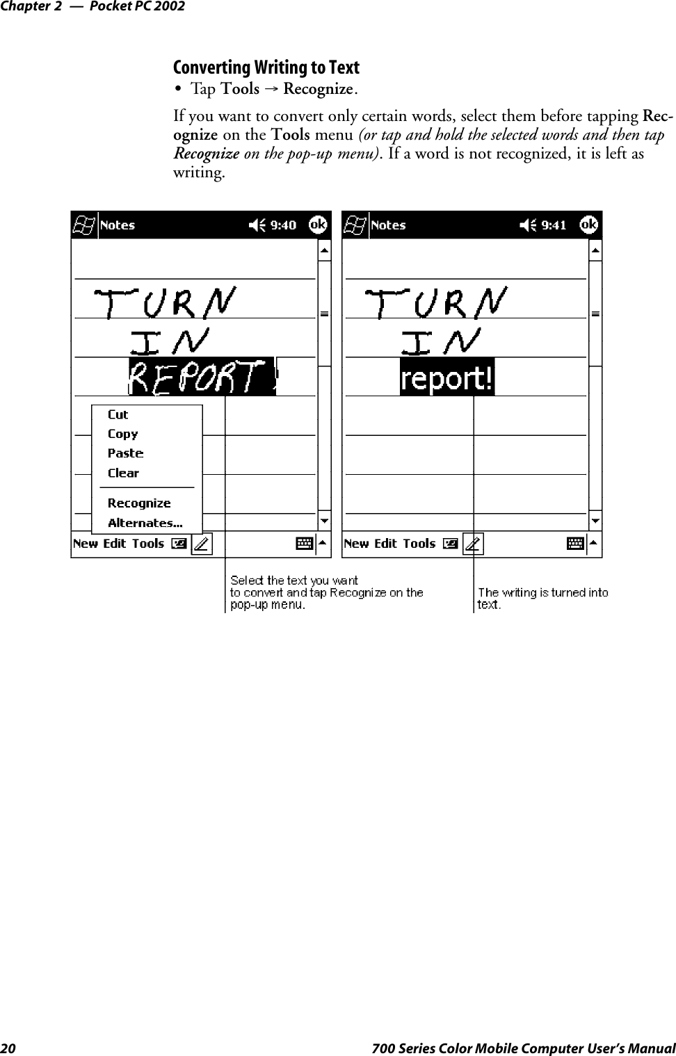
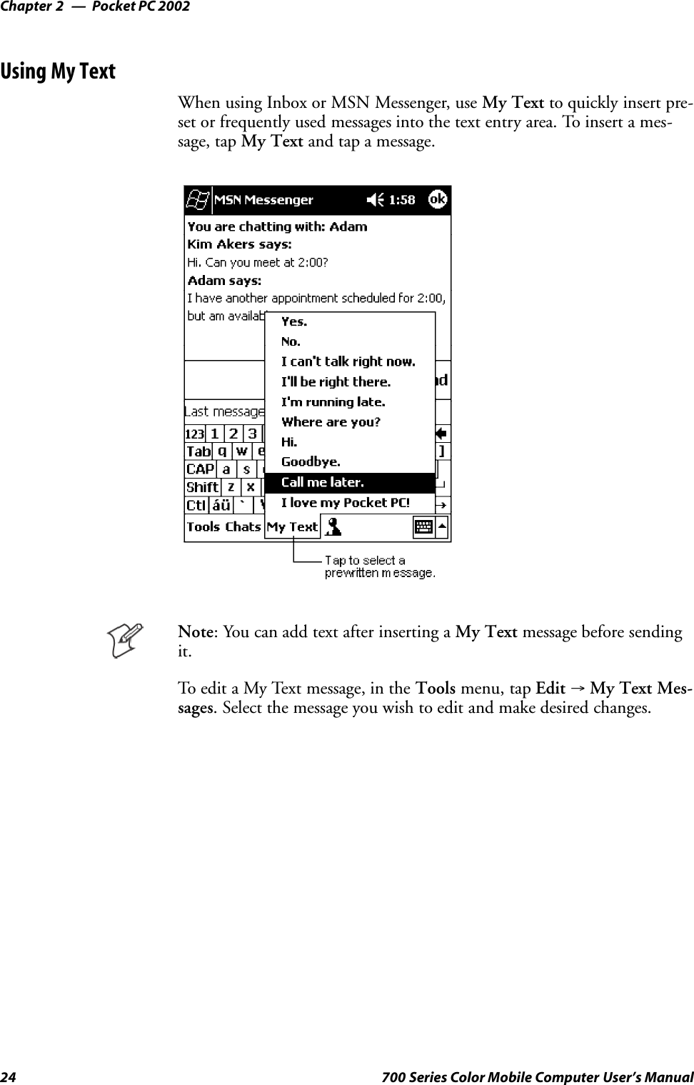
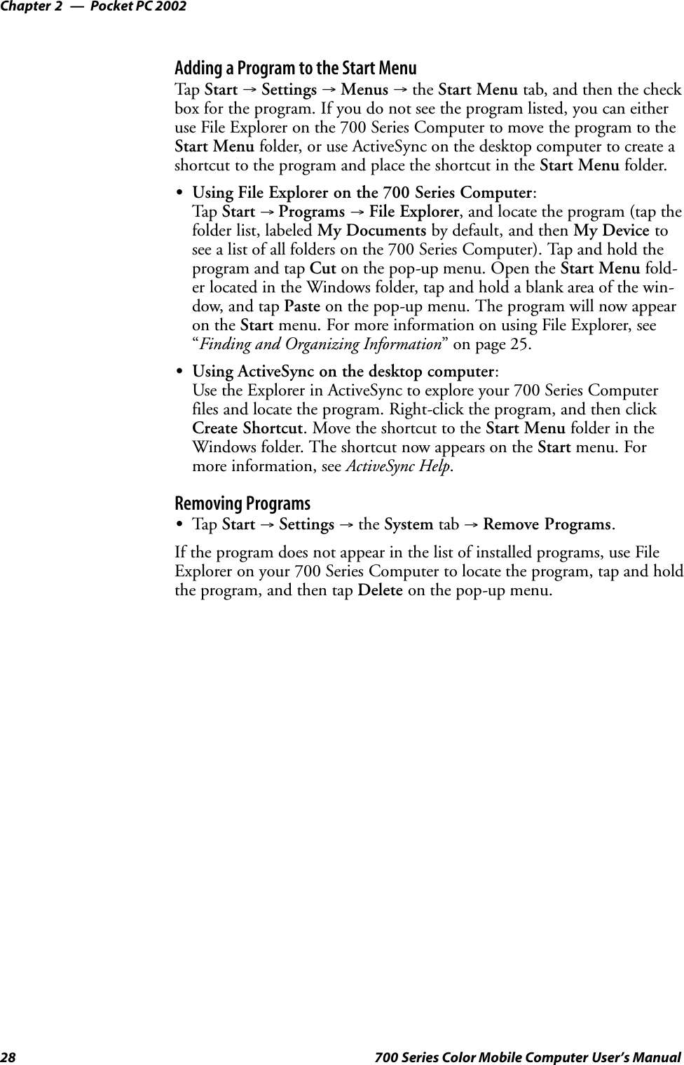
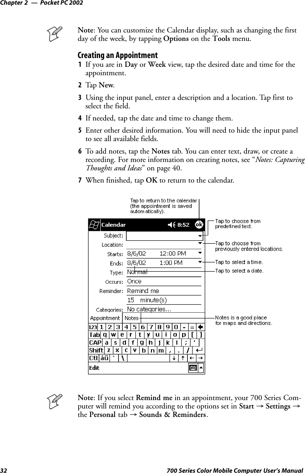
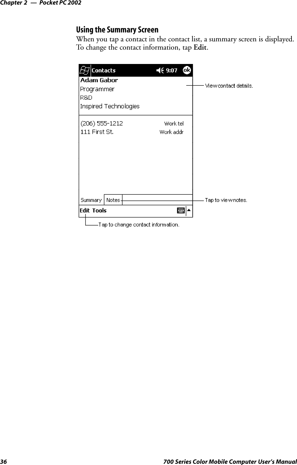
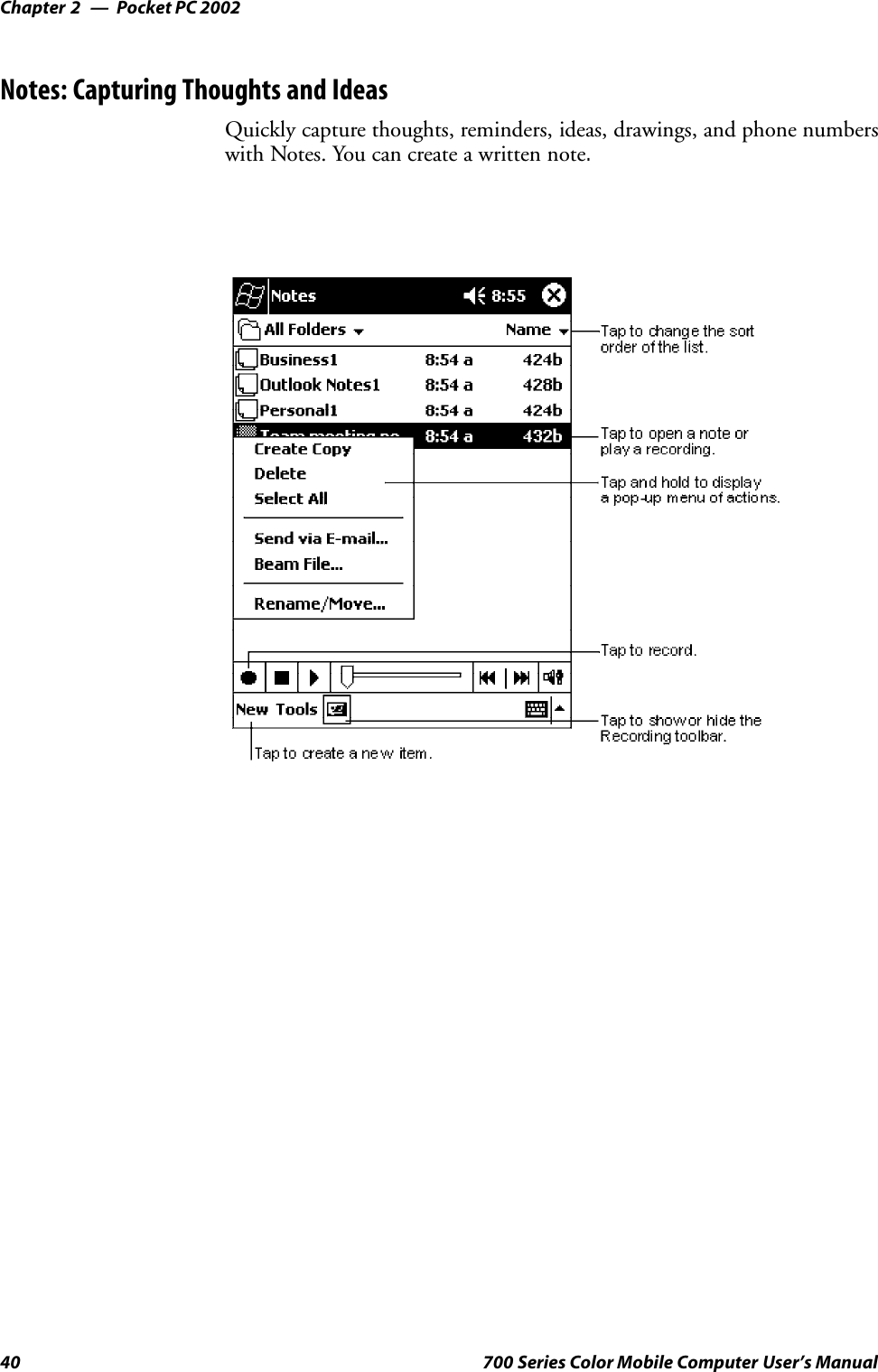
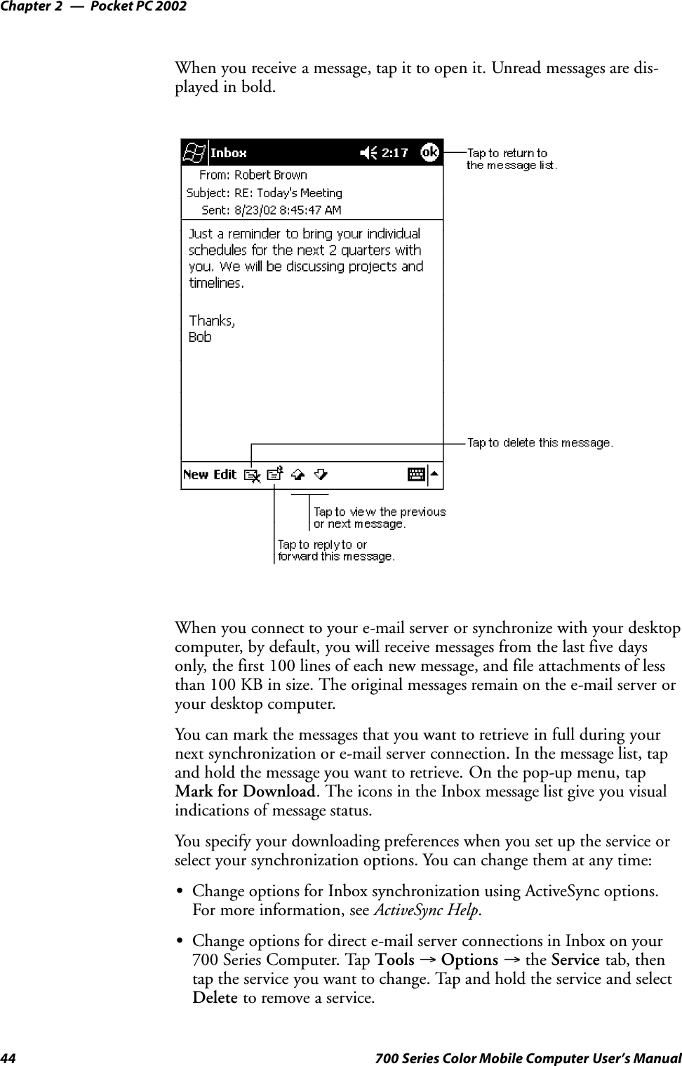
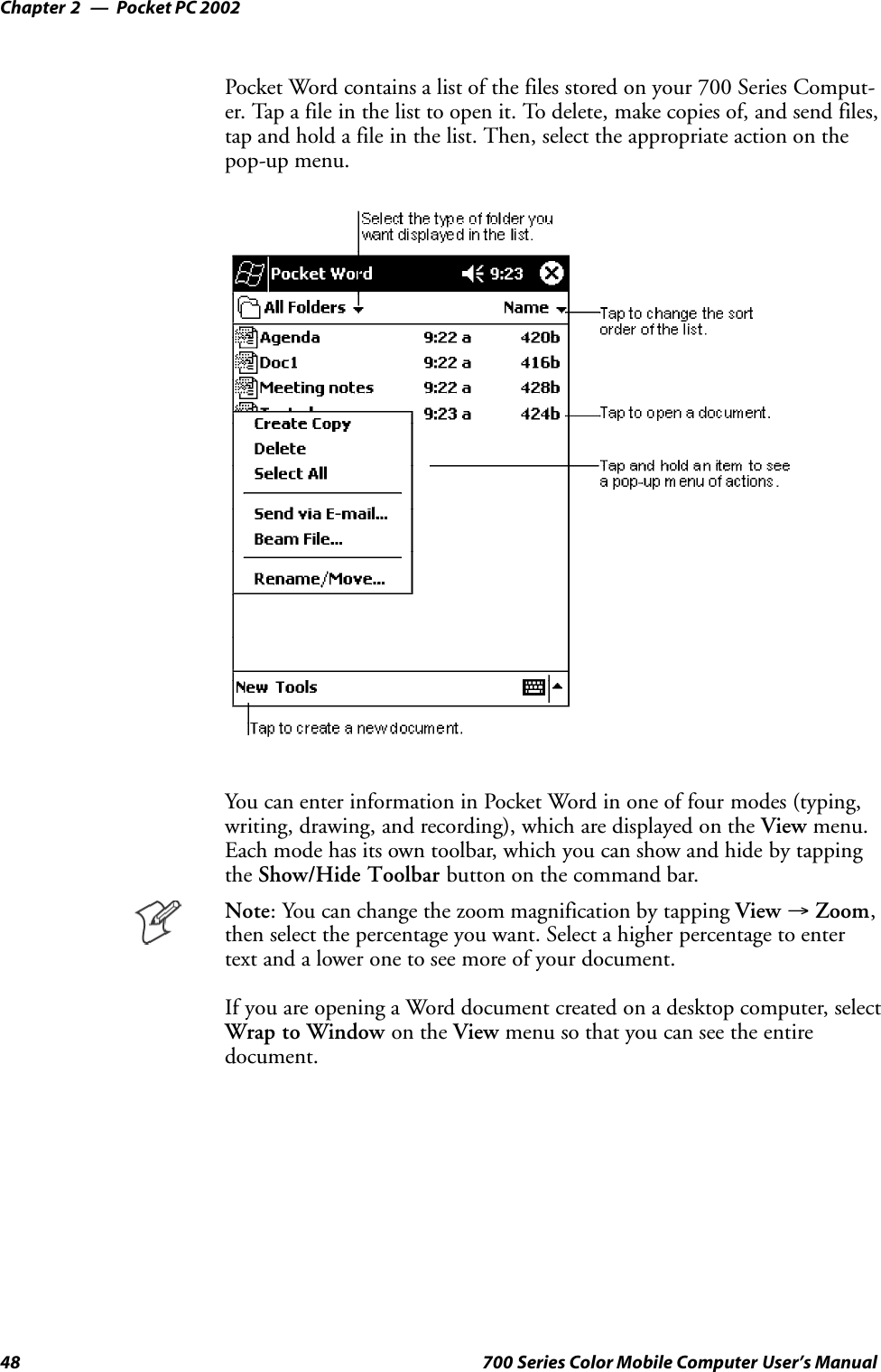
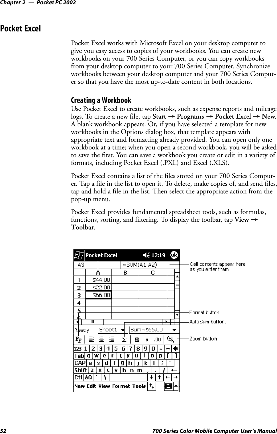
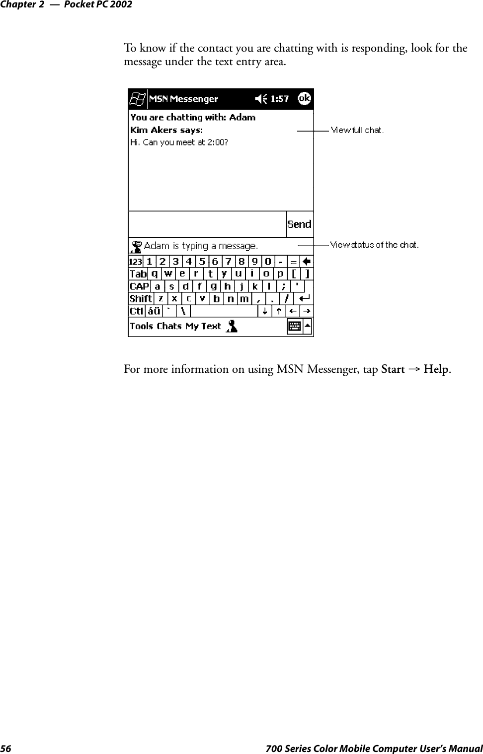
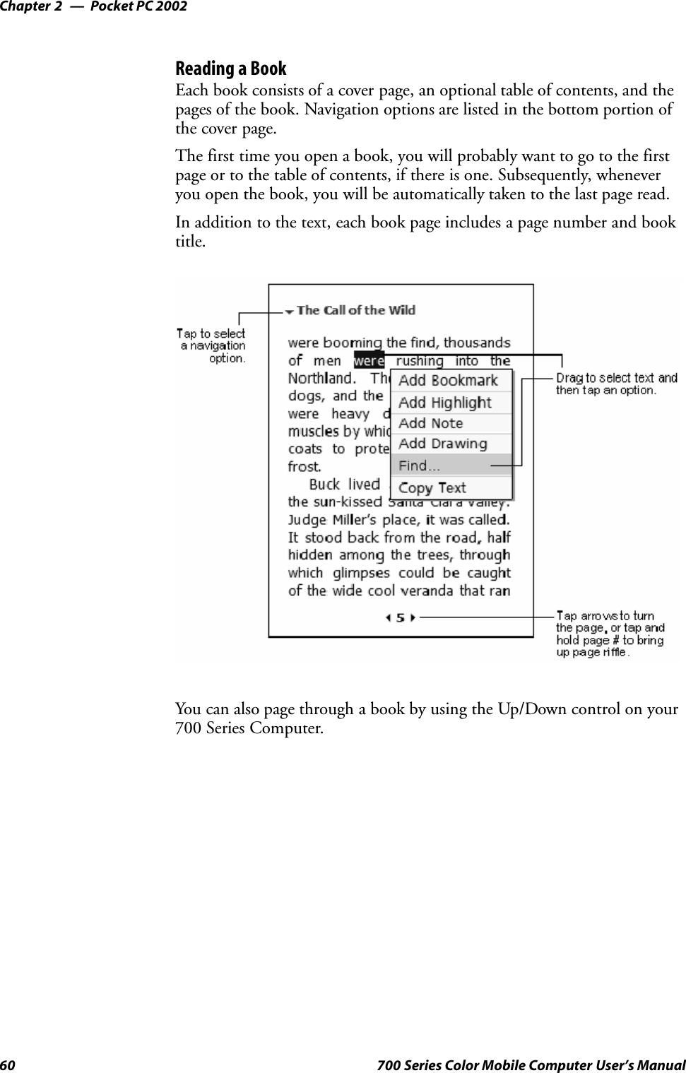
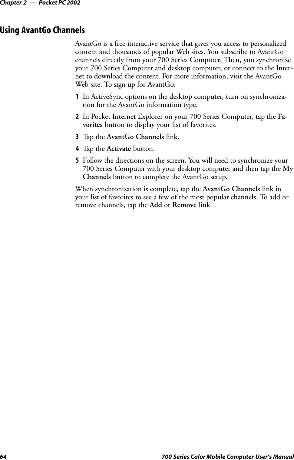
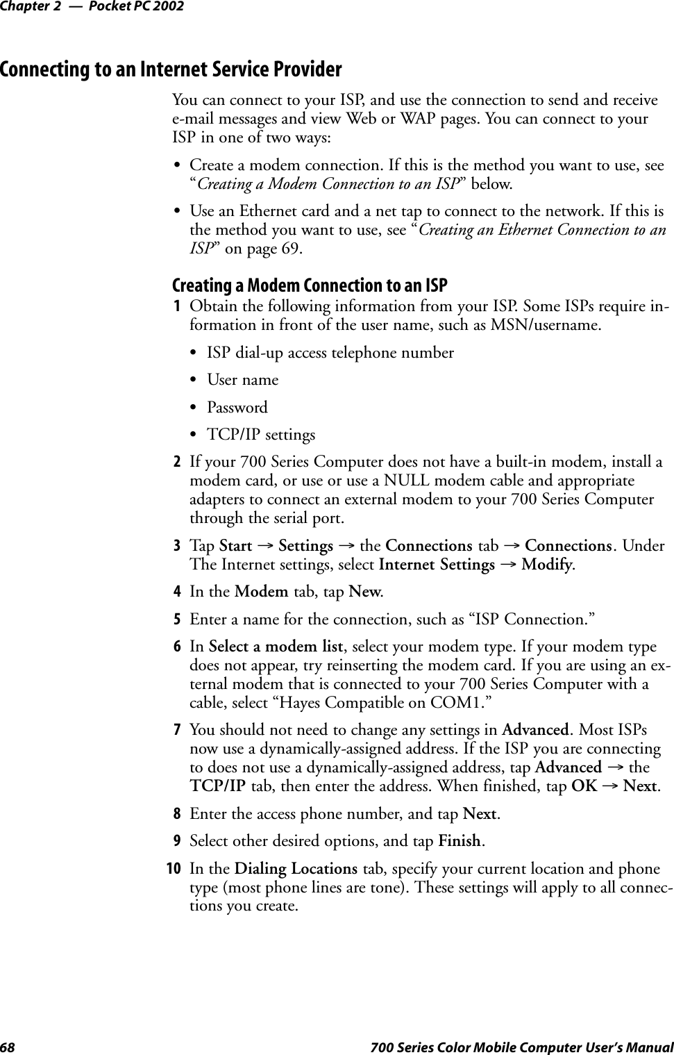
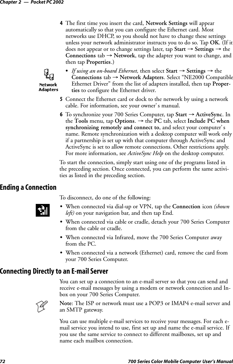
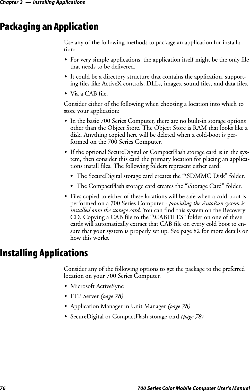
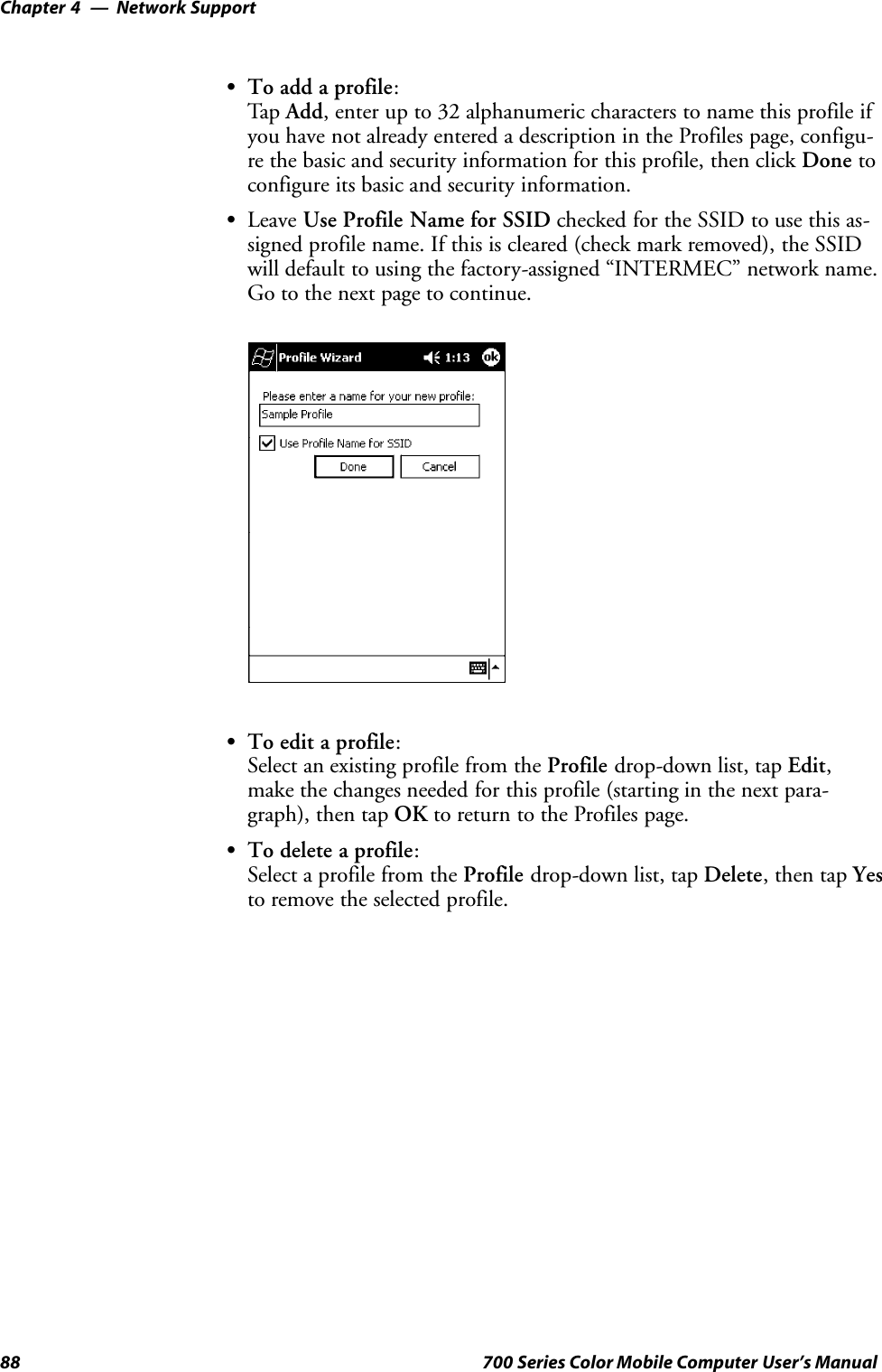
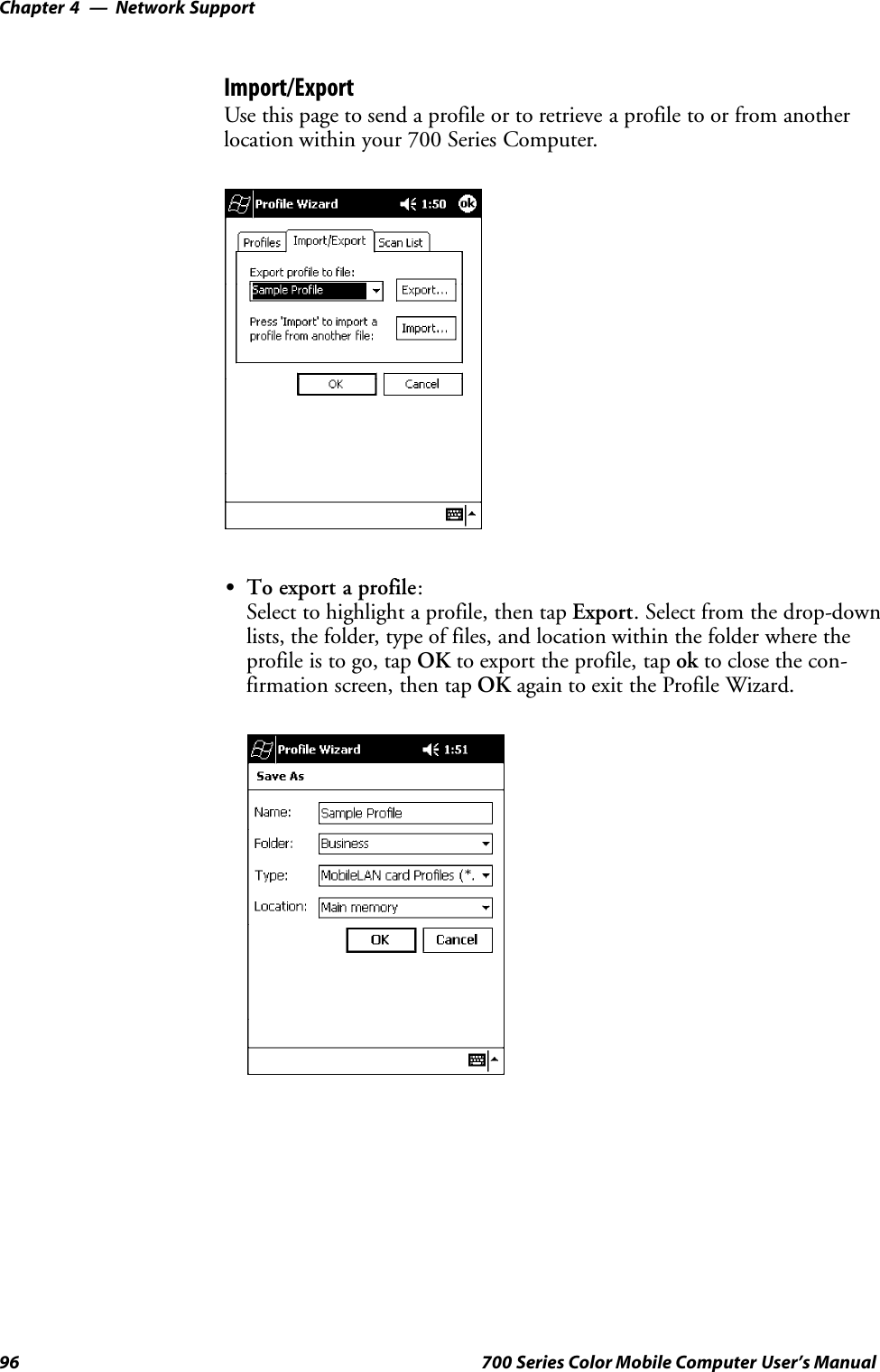
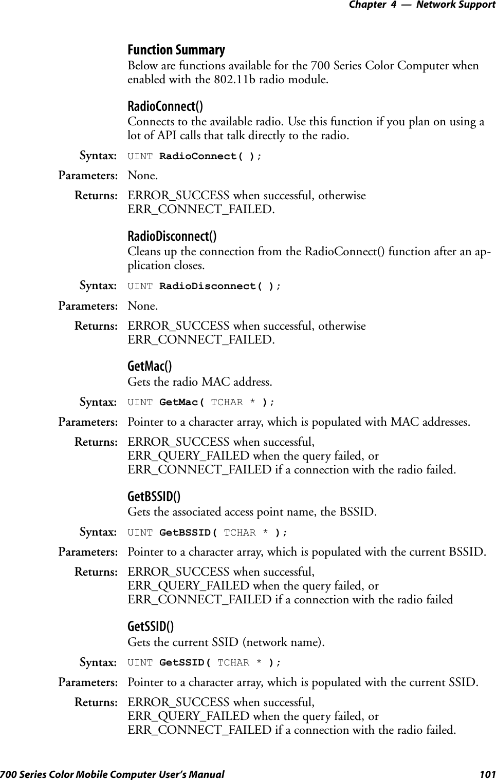
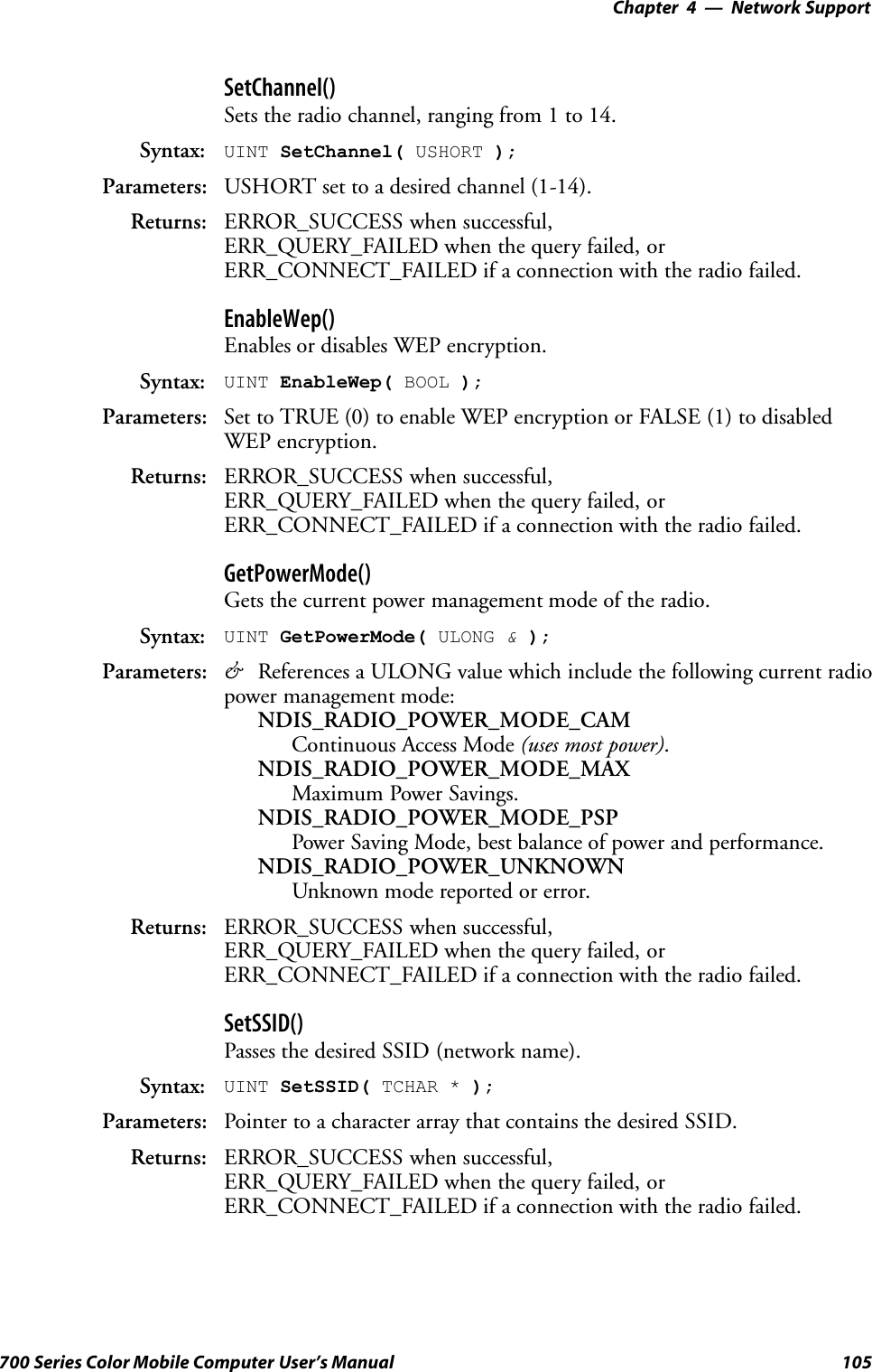
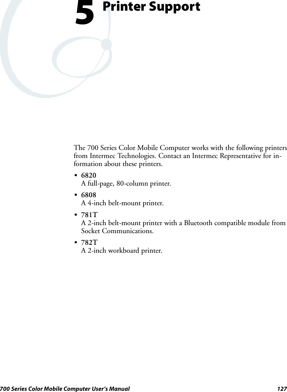
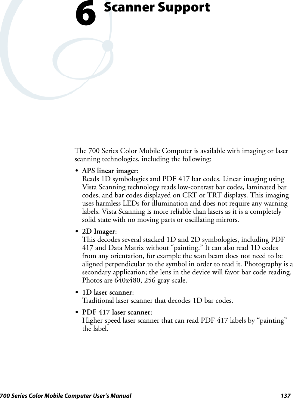
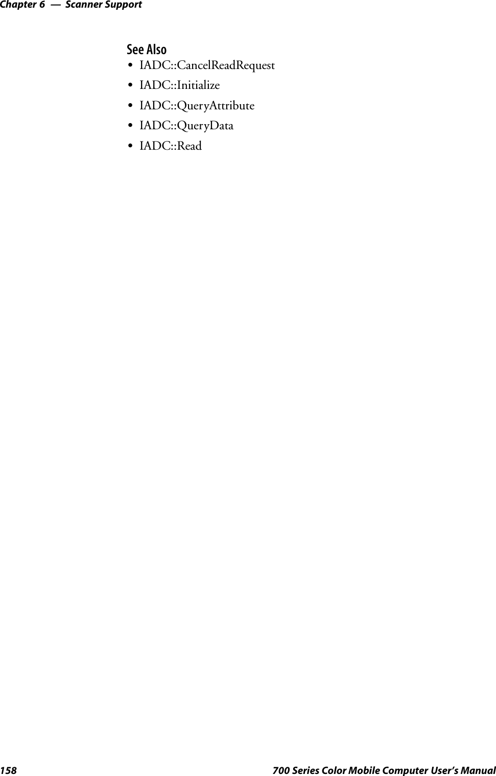
![Network Support—Chapter 499700 Series Color Mobile Computer User’s Manual#include <winioctl.h>#include “sysio.h”void DoLoad(int nDevice) {LPTSTR devs[] = { _T(“SYI1:”), _T(“FWV1:”) };HANDLE hLoaderDev;DWORD bytesReturned;hLoaderDev = CreateFile(devs[nDevice], GENERIC_READ|GENERIC_WRITE, 0,NULL, OPEN_EXISTING, 0, NULL);if (hLoaderDev != INVALID_HANDLE_VALUE) {if (!DeviceIoControl( hLoaderDev, IOCTL_LOAD_NDIS_MINIPORT, NULL, -1, NULL, 0,&bytesReturned, NULL)){MessageBox(NULL, TEXT(“SYSIO IoControl Failed”), TEXT(“Networkloader”),MB_ICONHAND);if (hLoaderDev!=INVALID_HANDLE_VALUE) CloseHandle(hLoaderDev);hLoaderDev = INVALID_HANDLE_VALUE; // bad handle}else {CloseHandle(hLoaderDev);}}}void DoUnload(int nDevice) {LPTSTR devs[] = { _T(“SYI1:”), _T(“FWV1:”) };HANDLE hLoaderDev;DWORD bytesReturned;hLoaderDev = CreateFile(devs[nDevice], GENERIC_READ|GENERIC_WRITE, 0,NULL, OPEN_EXISTING, 0, NULL);if (hLoaderDev != INVALID_HANDLE_VALUE) {if (!DeviceIoControl( hLoaderDev, IOCTL_UNLOAD_NDIS_MINIPORT, NULL, -1, NULL, 0,&bytesReturned, NULL)){MessageBox(NULL, TEXT(“SYSIO IoControl Failed”),TEXT(“Networkloader”),MB_ICONHAND);if (hLoaderDev!=INVALID_HANDLE_VALUE) CloseHandle(hLoaderDev);hLoaderDev = INVALID_HANDLE_VALUE; // bad handle}else {CloseHandle(hLoaderDev);}}}](https://usermanual.wiki/Intermec-Technologies/SB555.Item-5-from-FCC-email-Feb-07-2003/User-Guide-307179-Page-117.png)
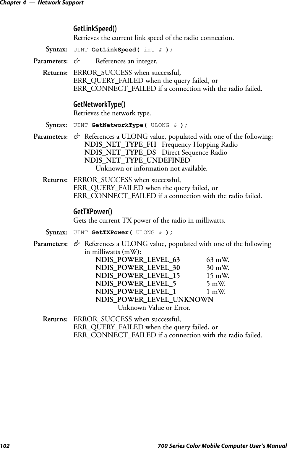
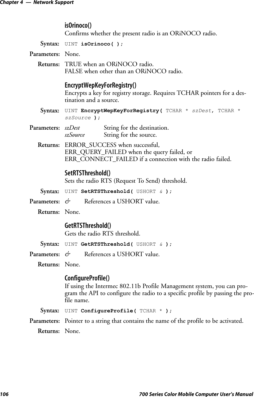
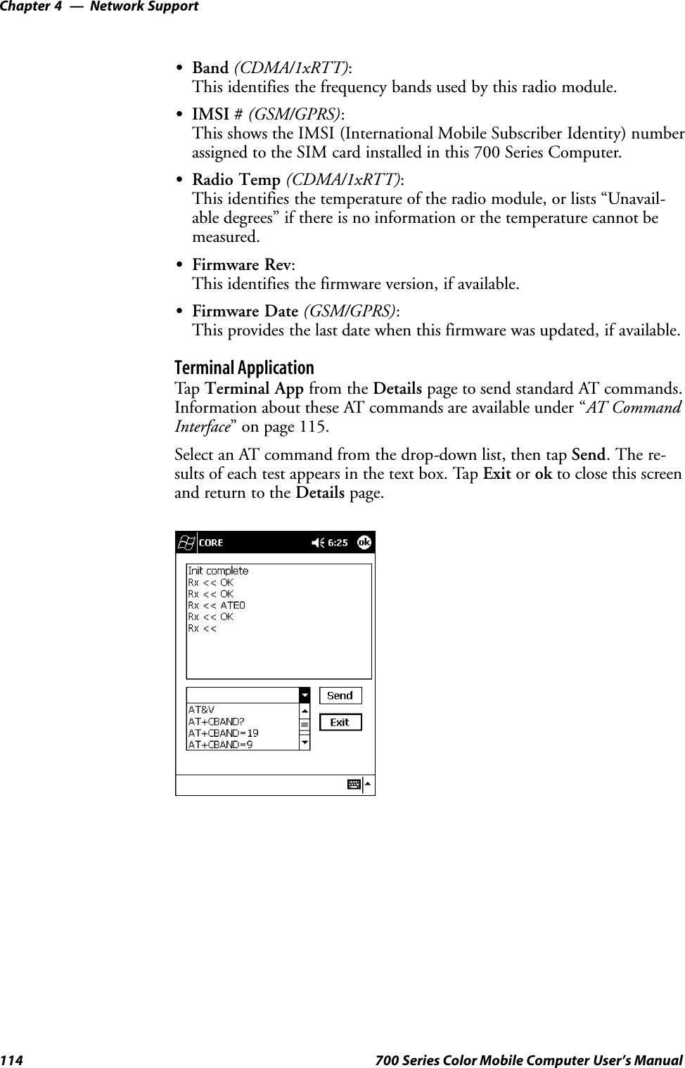
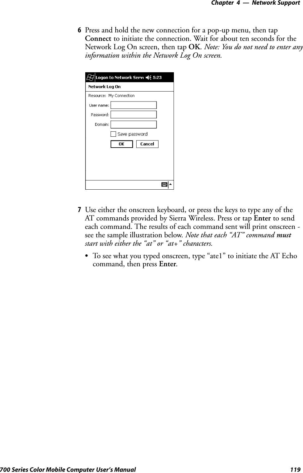
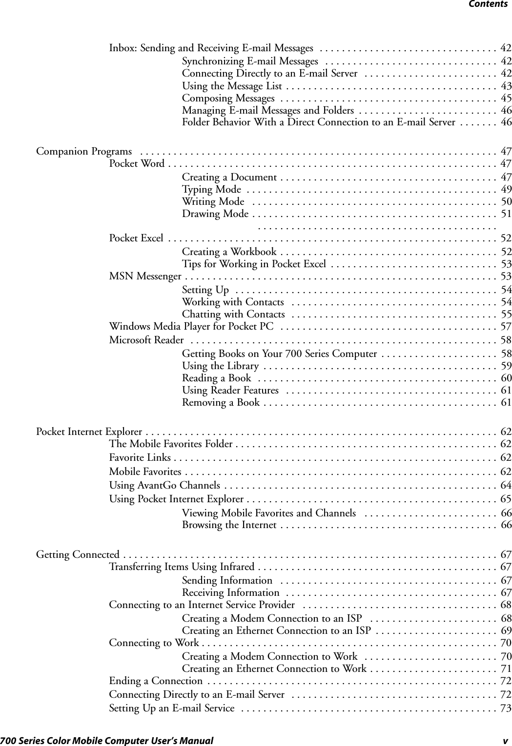
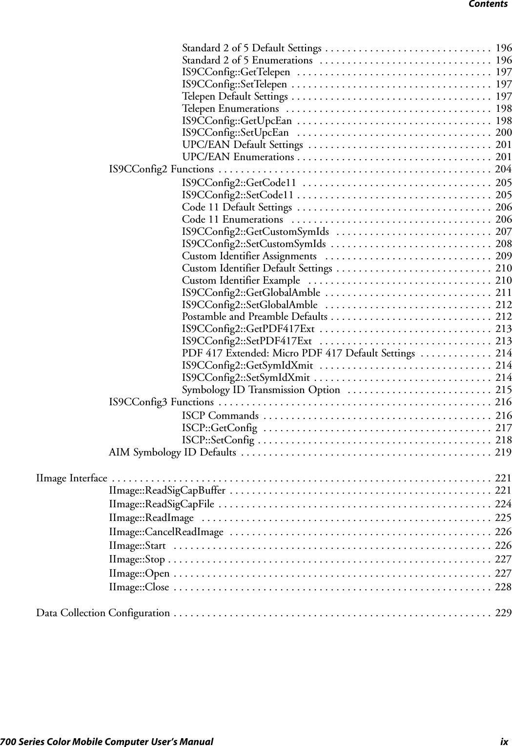
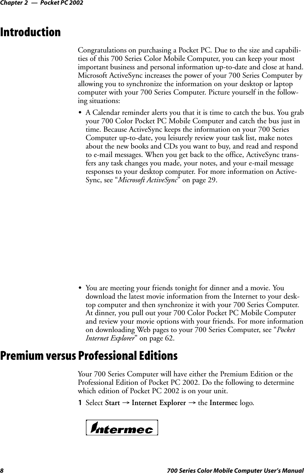
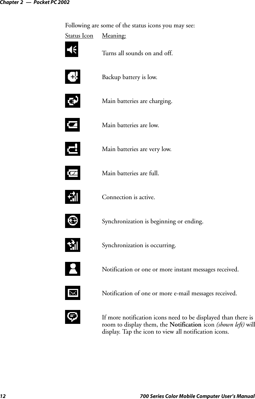
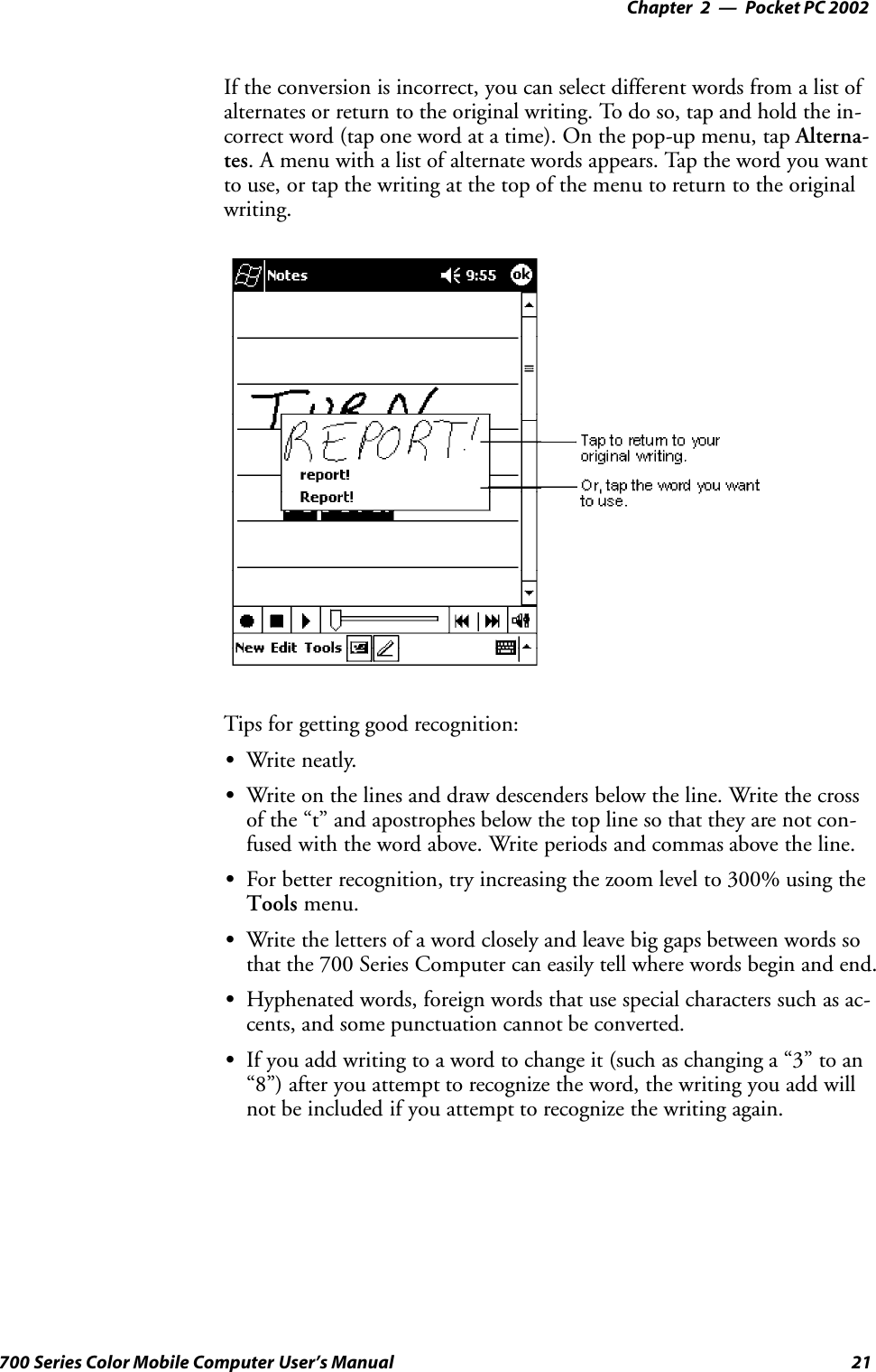
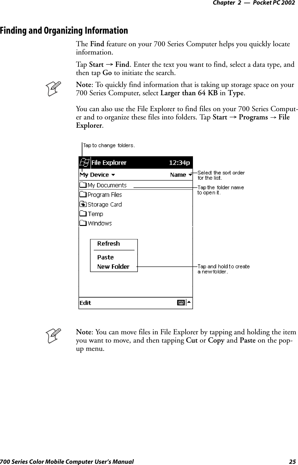
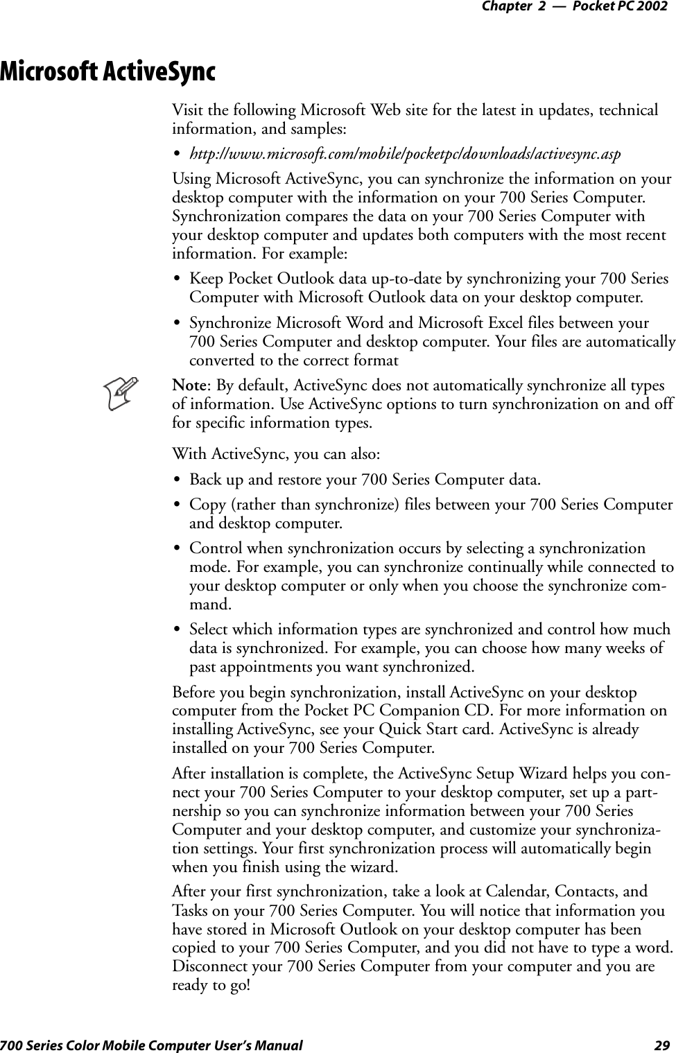
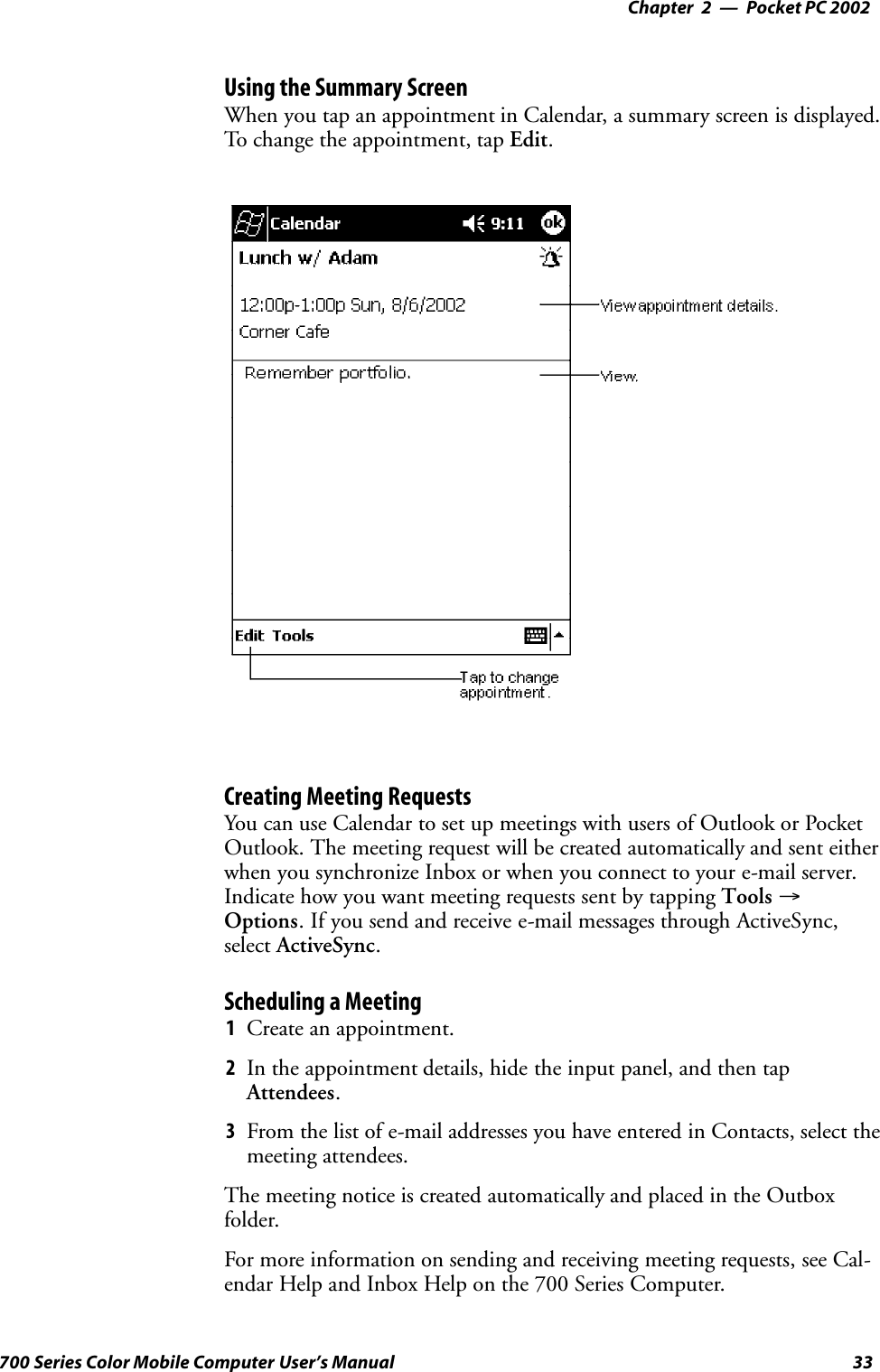
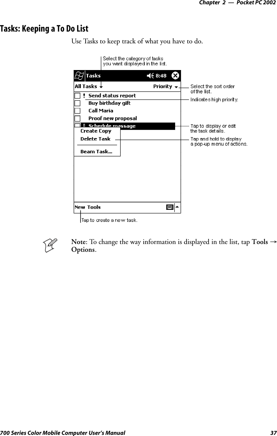
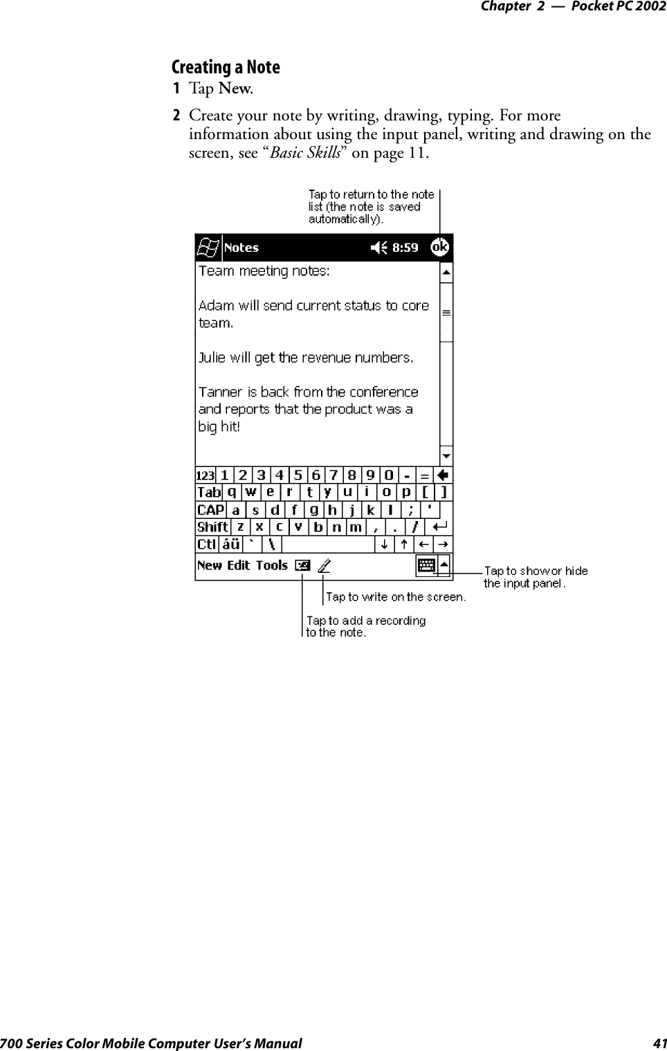
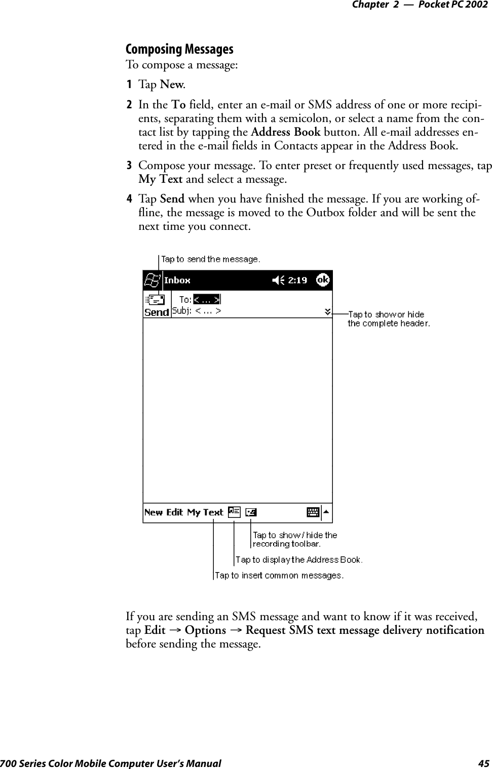
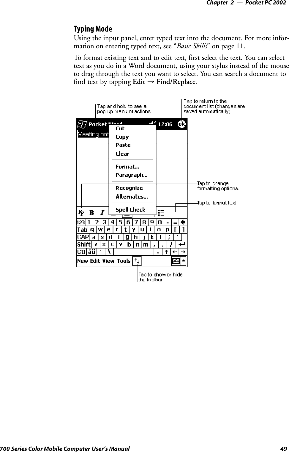
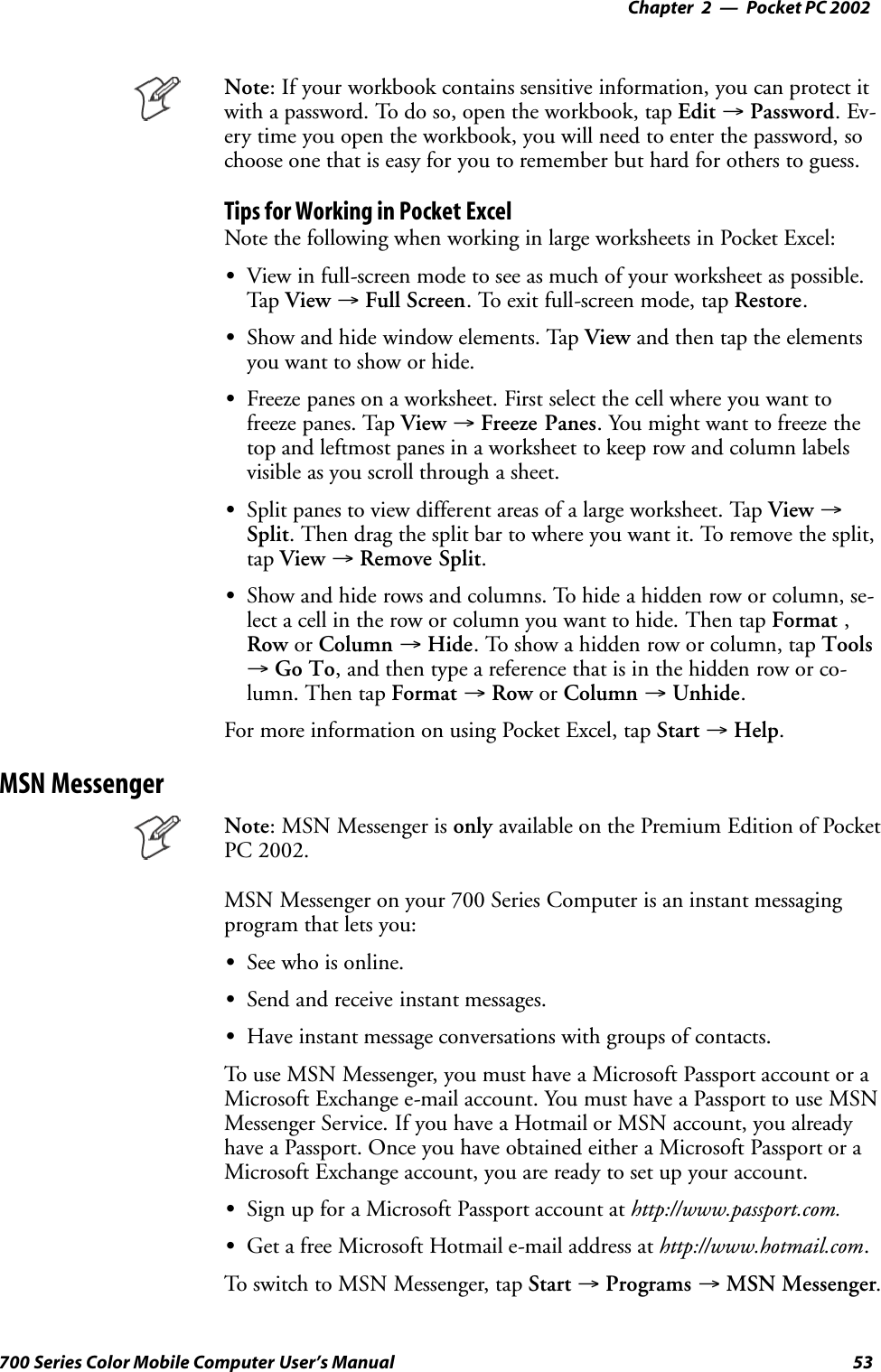
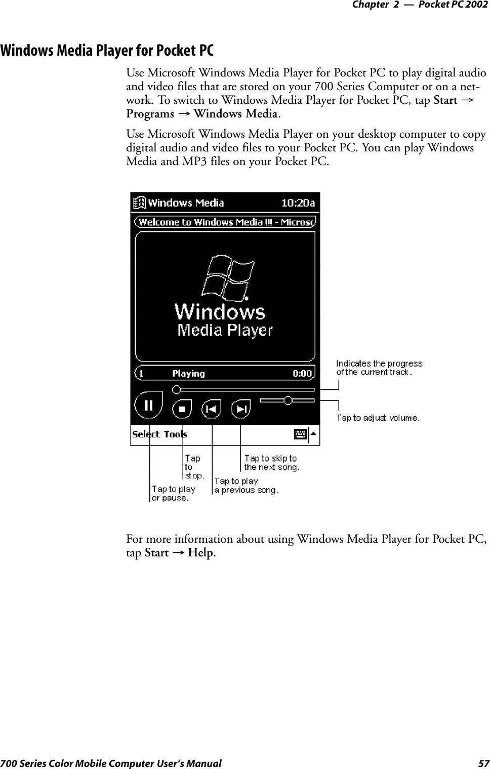
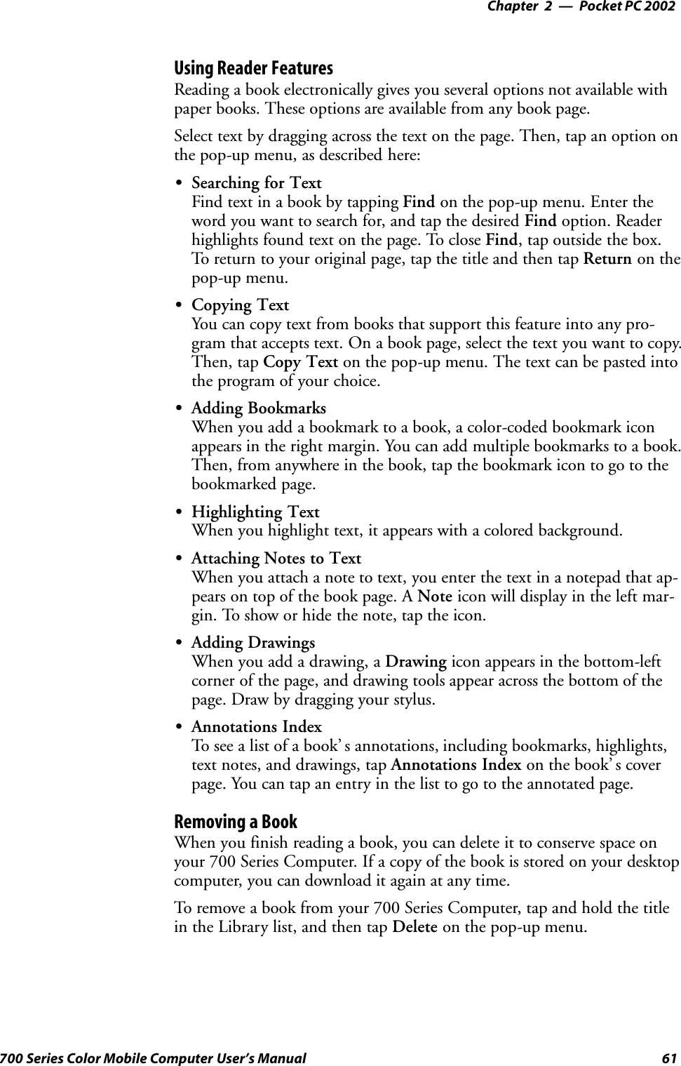
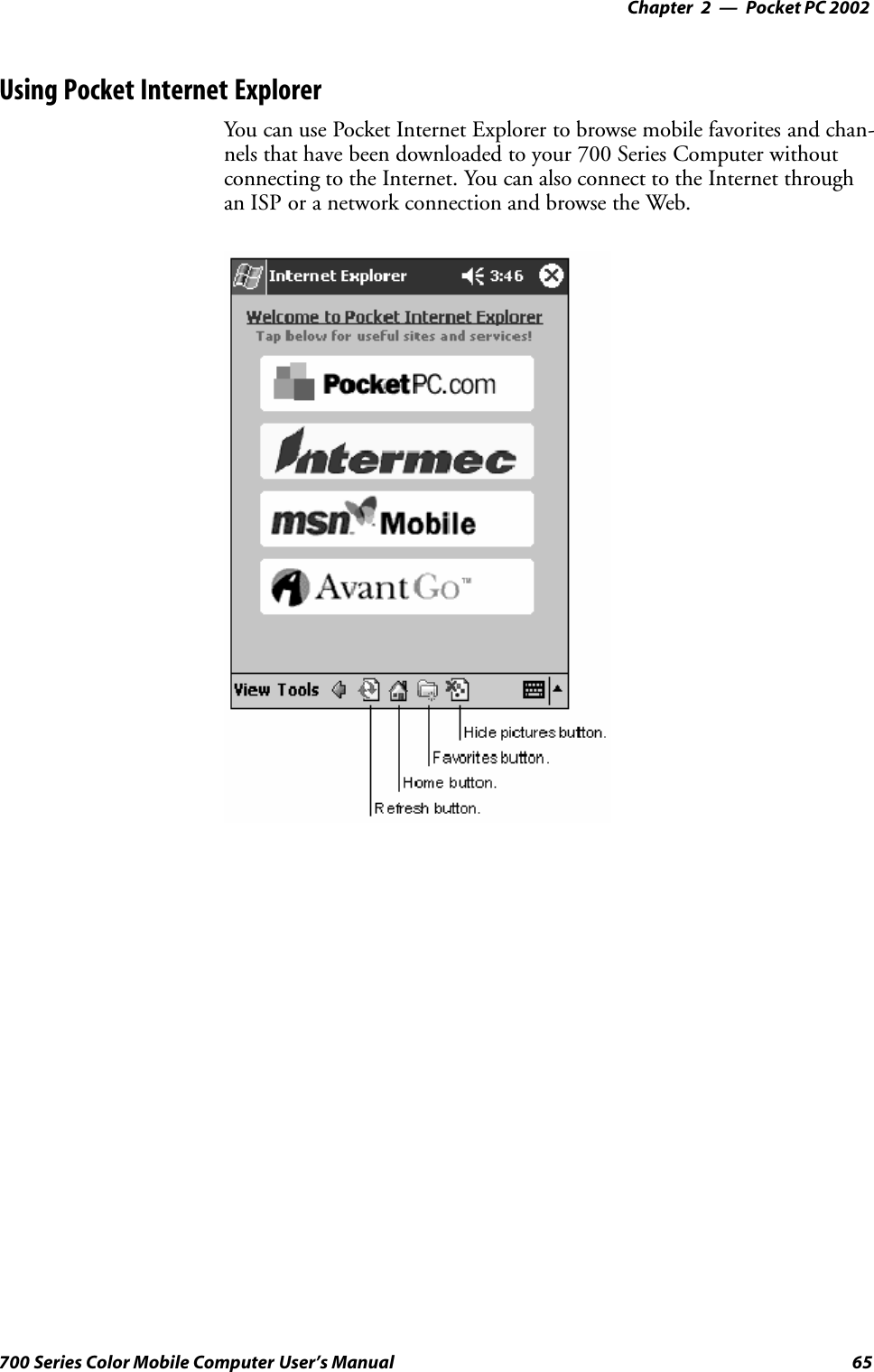
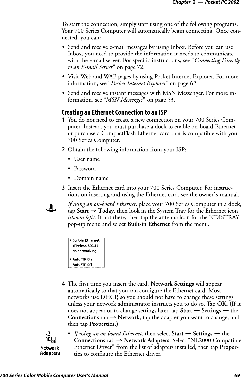
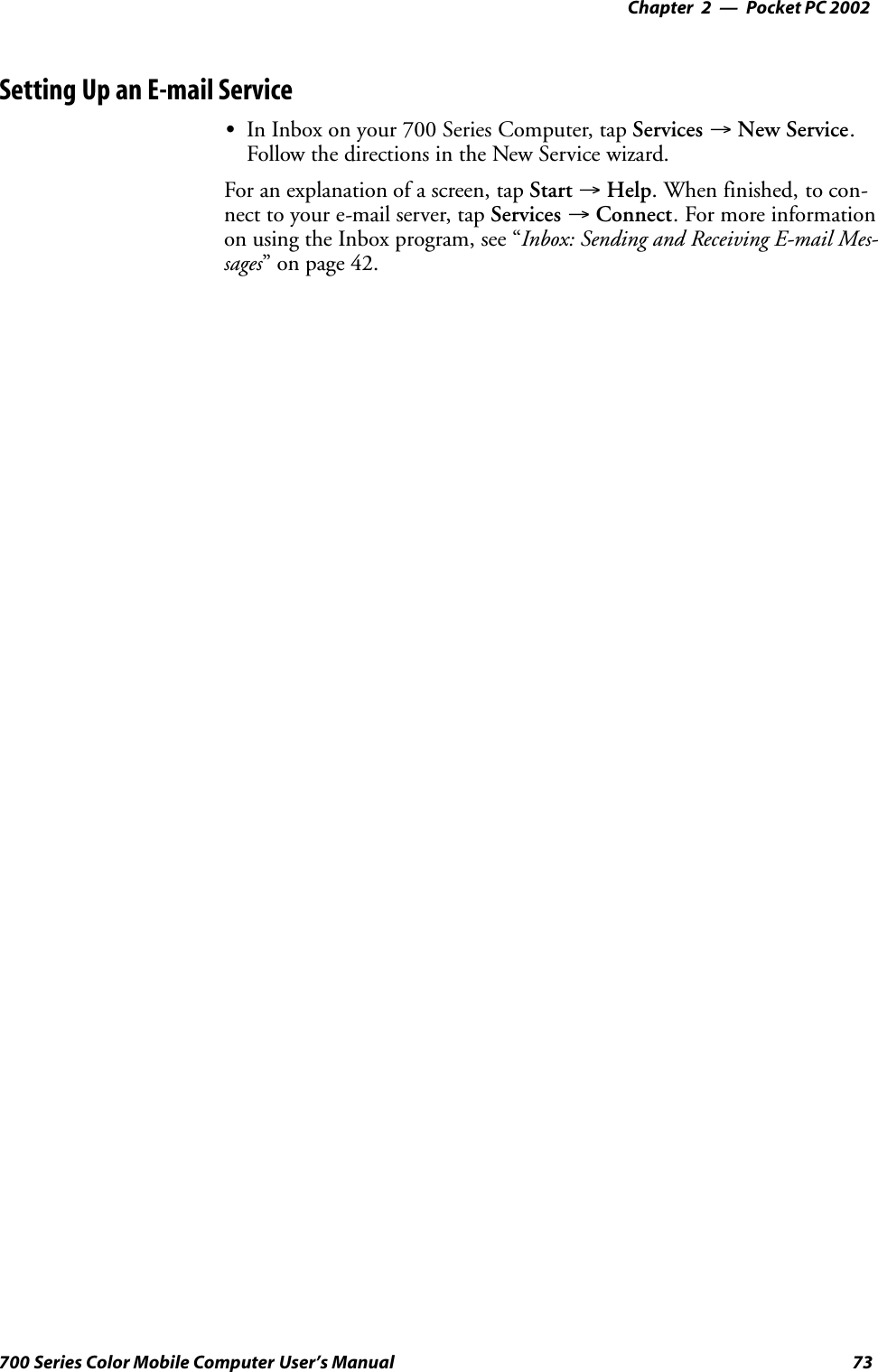
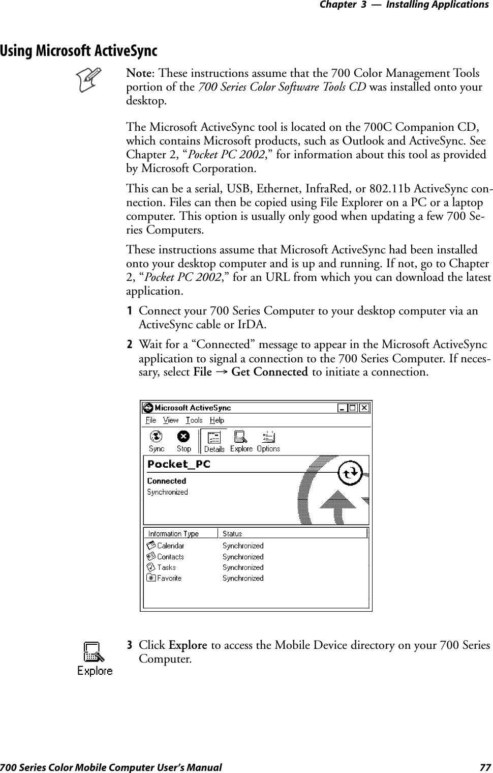
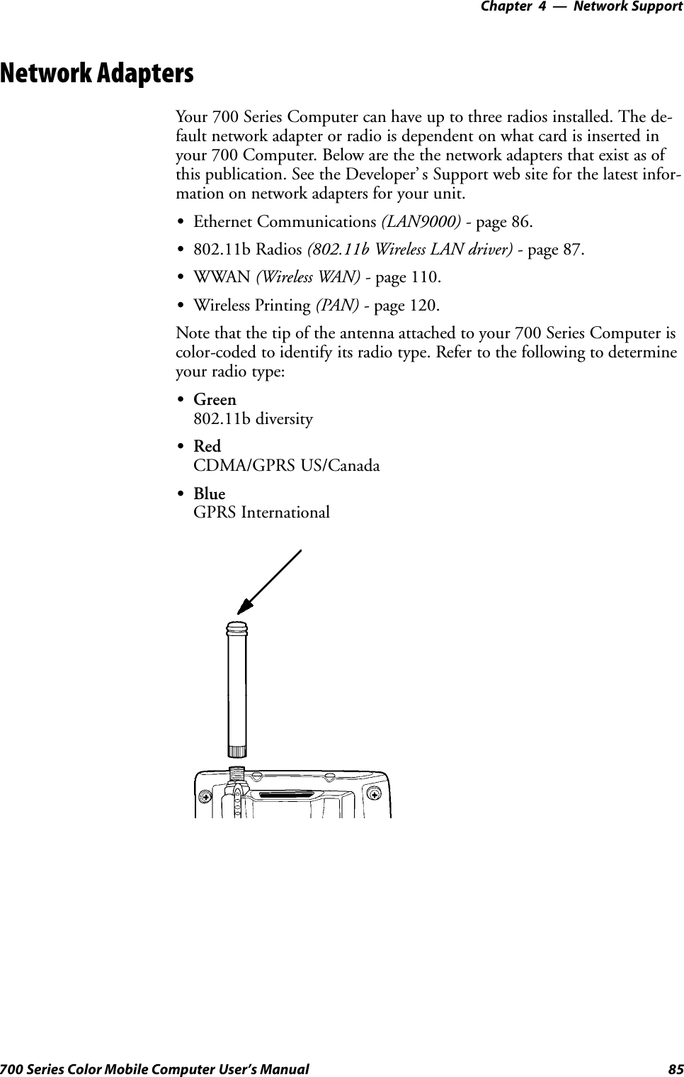
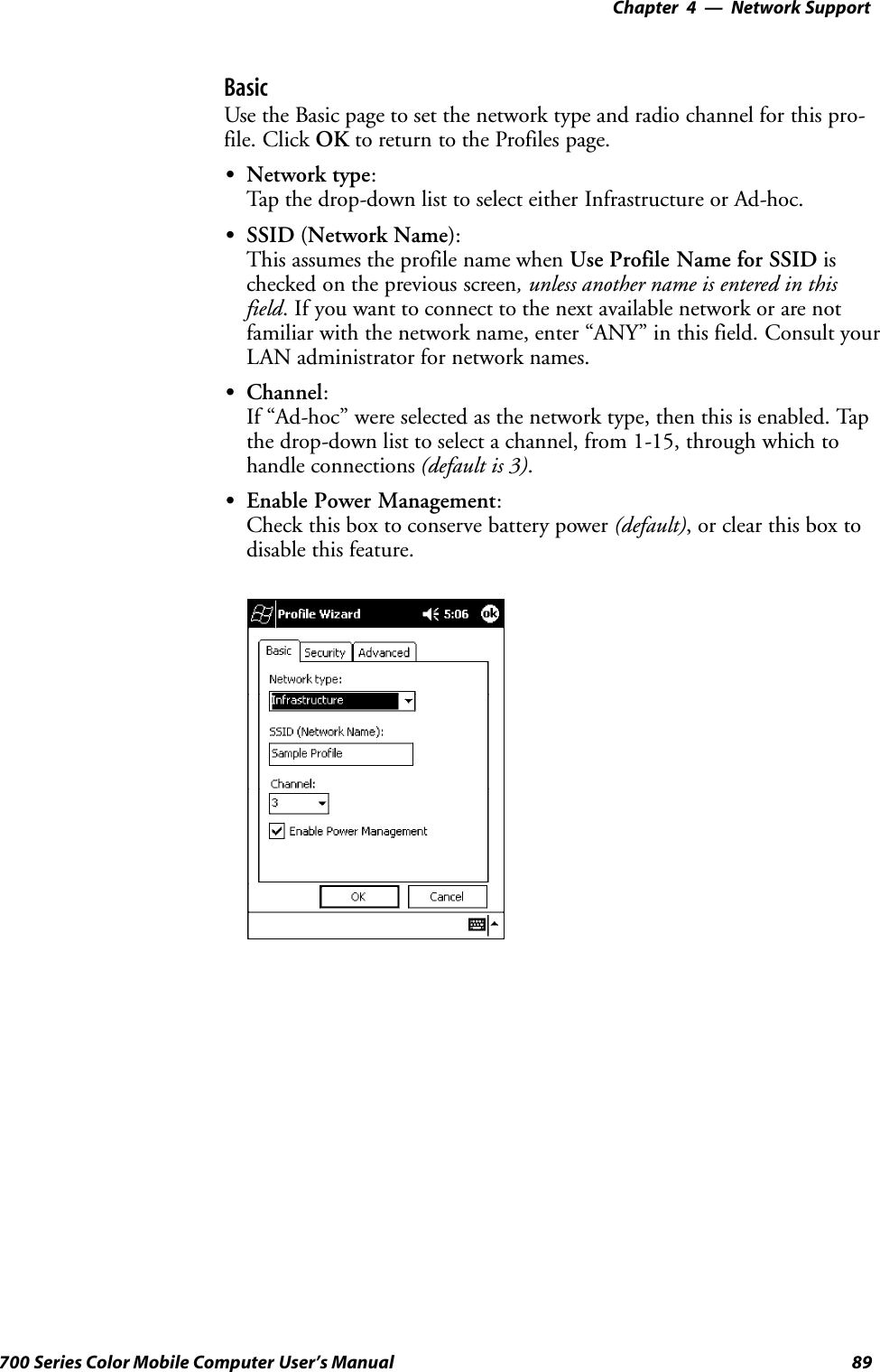
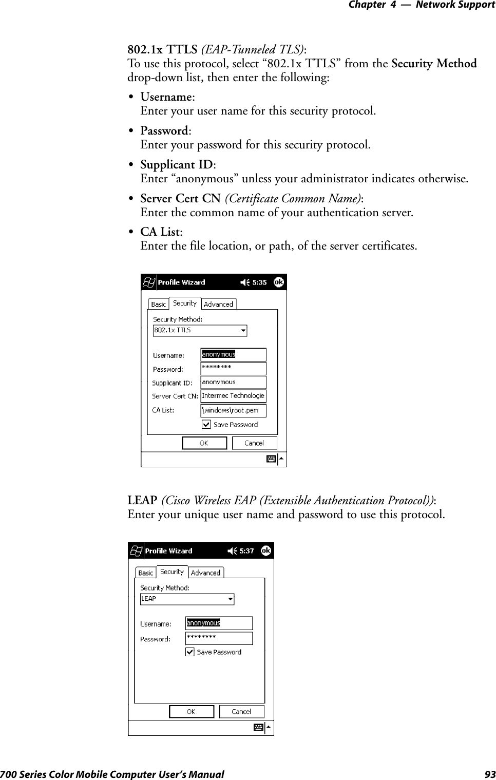
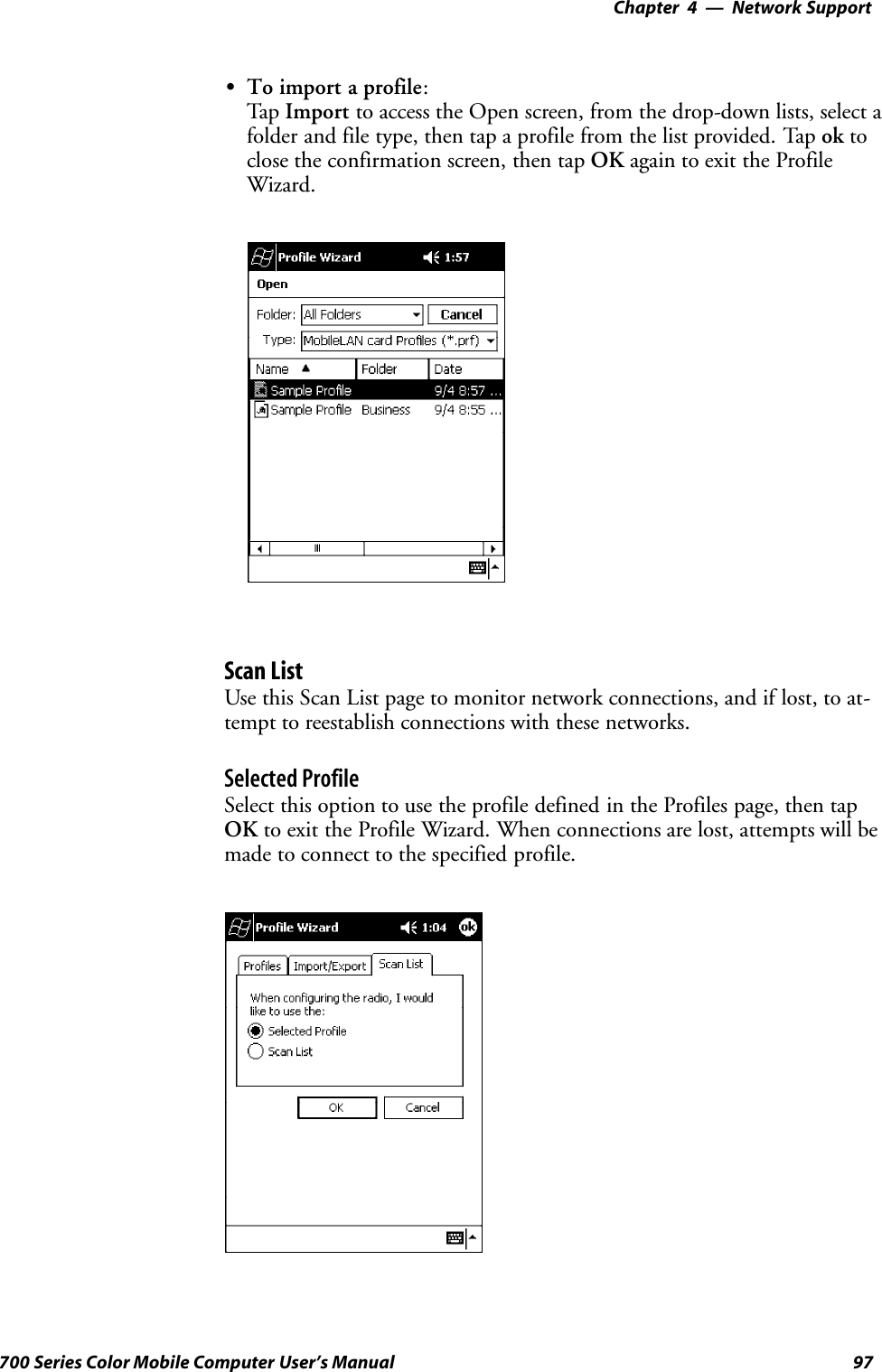
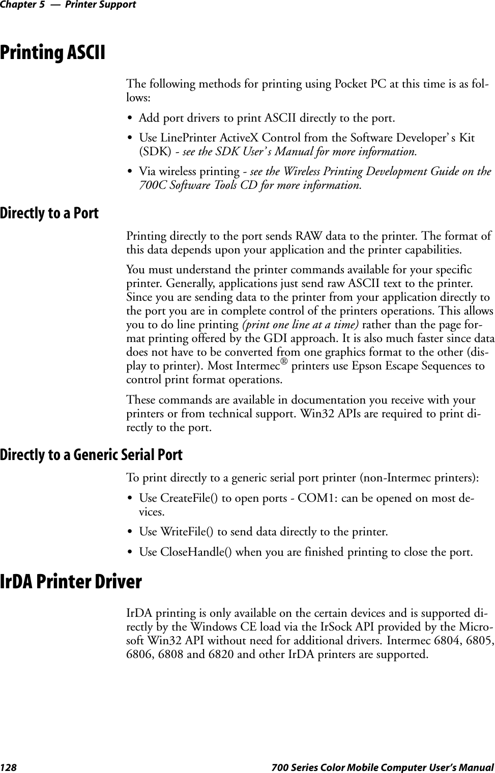
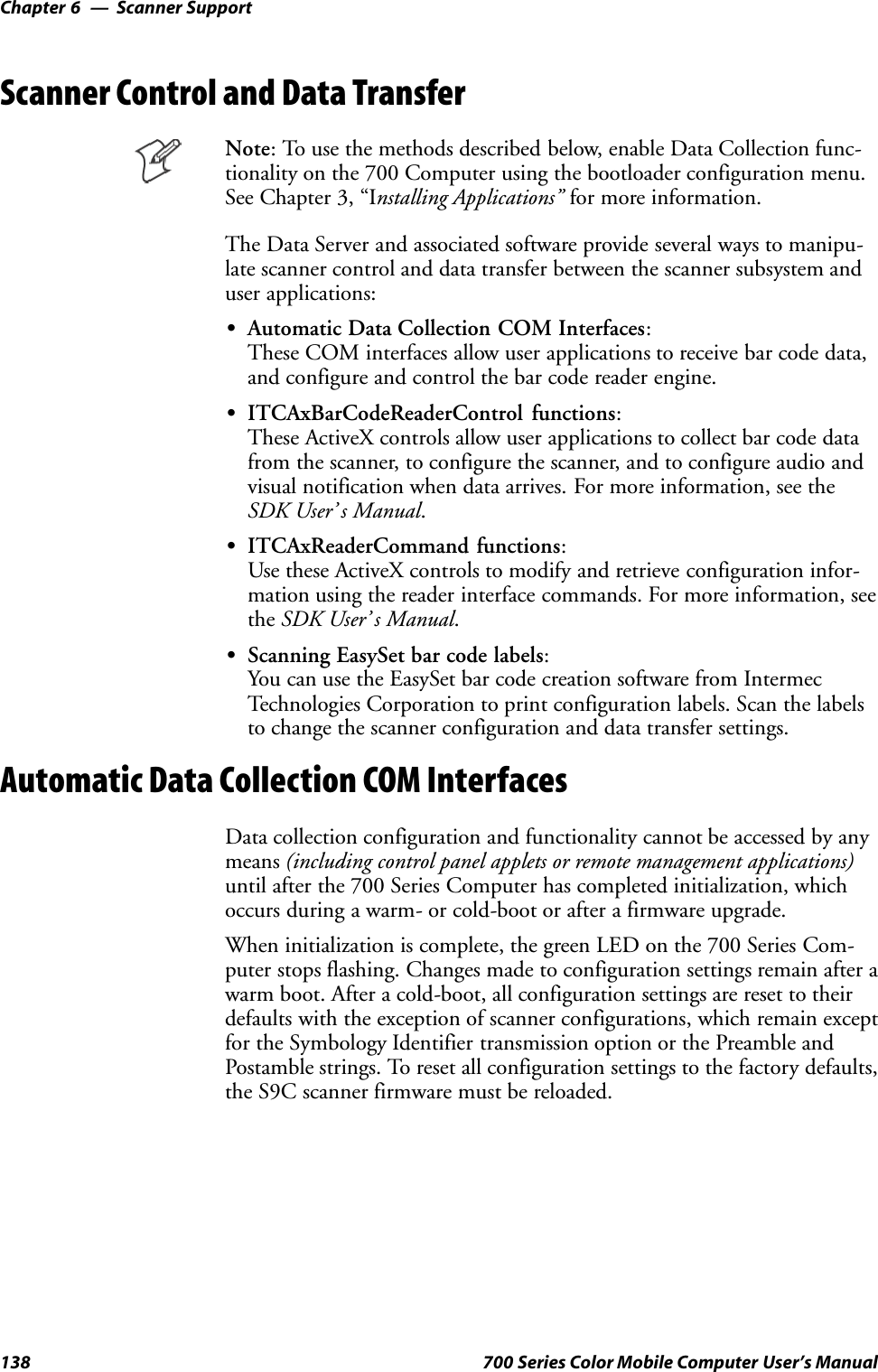
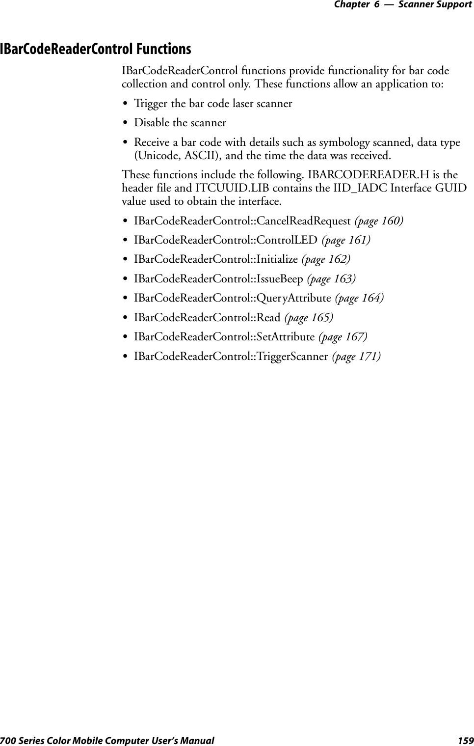
![Network Support—Chapter 4121700 Series Color Mobile Computer User’s ManualSBluetooth Point to Point:This is the network type. “Point to Point” is the type of connection sup-ported as of this publication. Scatternets are not supported. The only sup-ported application is wireless printing to Intermec wireless printers, suchas the 781T Belt-Mount Printer.SDevice Address:This provides the network address, which in this case, will be replacedby the device address of the Bluetooth compatible module within your700 Series Computer. Note that this address is universally unique.SDiscoverable:The following is displayed depending on whether the 700 Series Com-puter is configured to be discoverable:“Gen” Generally discoverable“Lim” Limited discovery“No” Not discoverableSConnectable:This defines whether the 700 Series Computer is able to accept otherdevices with Bluetooth compatible modules connecting to it. “Yes” if theconnection is doable, “No” if not.SBondable:This defines the security element of the 700 Series Computer, which isthe bondable setting. If the unit is bondable, then “Yes” is displayed,otherwise “No” is displayed.SModule Firmware:This reflects the firmware (hardware) version of the 700 Series Comput-er. When the CORE module first installs onto the unit, the firmwarelevel is unknown, thus “...reading” is displayed. Once the firmware levelis read from the unit, then a three-digit decimal is displayed.SStack [Stack Version] [loaded/not loaded]:[Stack Version] displays the Bluetooth stack version, which appears in the“1.2.3.4” format. If the stack is loaded, then “loaded” is displayed afterthe stack version, otherwise “not loaded” is displayed.SDevice Name:This displays the device name as assigned to the Bluetooth compatiblemodule by the end-user. If the configured name is longer than the spaceallowed, it will be truncated.SBTpak Version:This displays the driver version of additional Bluetooth componentswithin the 700 Series Computer and is usually presented in the “1.2.3”format. The version may also contain a letter at either end.SHistory:This bar graph displays an active history of this wireless printer driver’ squality of connections.SFriendly Indicator:If the Bluetooth stack is loaded, then all three dots are filled. These dotsare left empty if the stack is not loaded. These dots do vary based on theCORE application’ s perception of the overall connection quality.](https://usermanual.wiki/Intermec-Technologies/SB555.Item-5-from-FCC-email-Feb-07-2003/User-Guide-307179-Page-138.png)
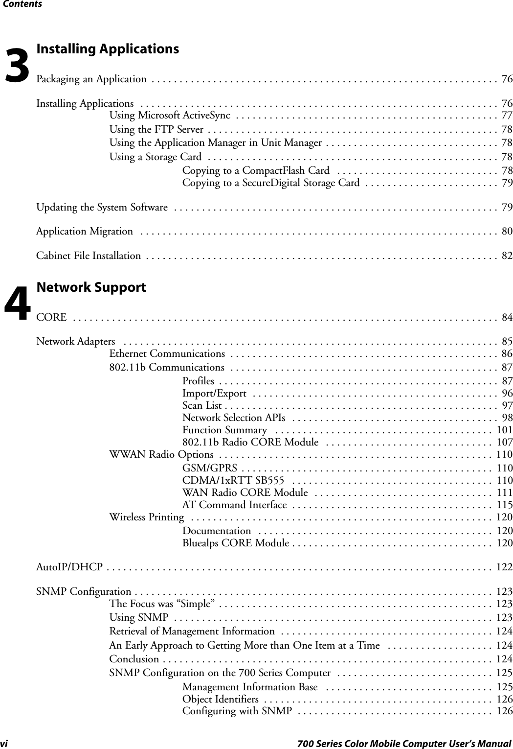
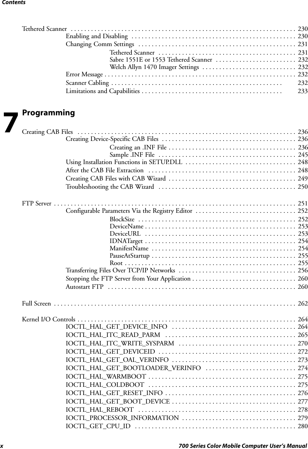
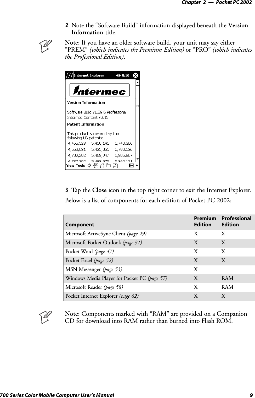
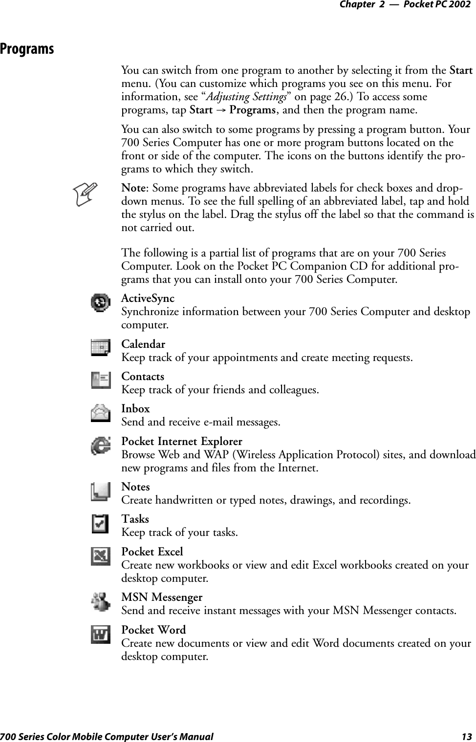
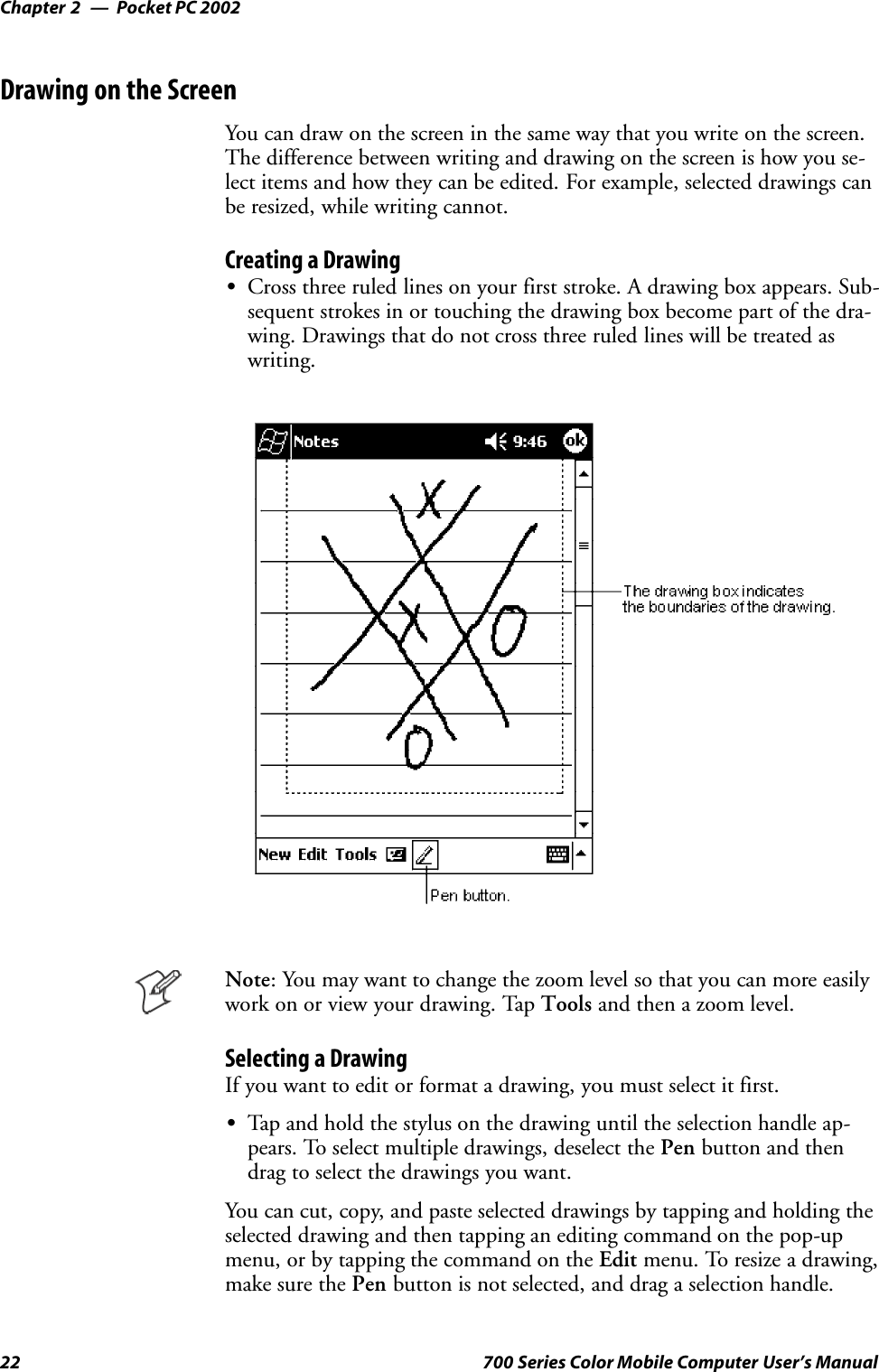
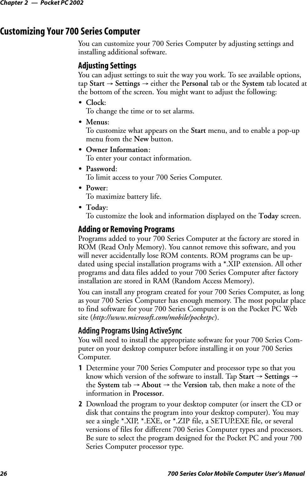
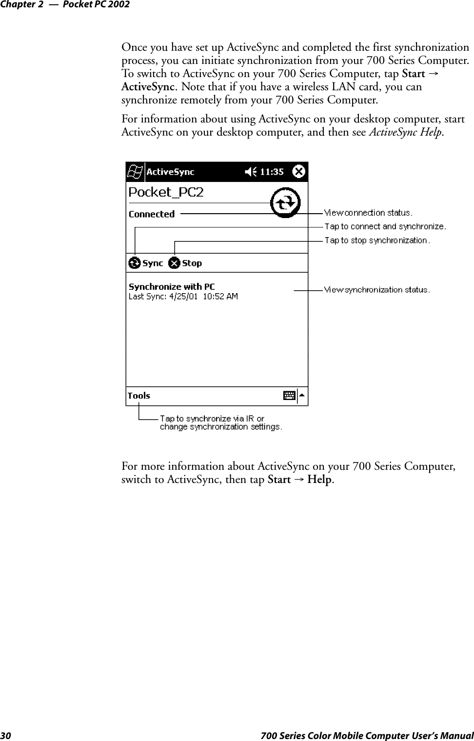
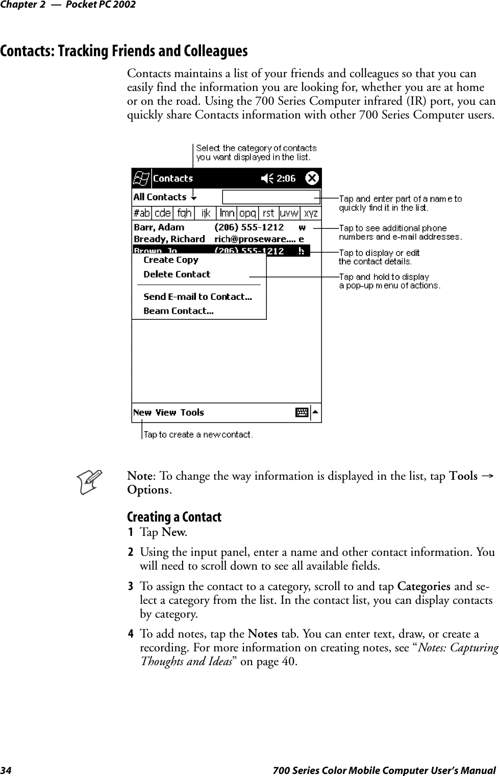
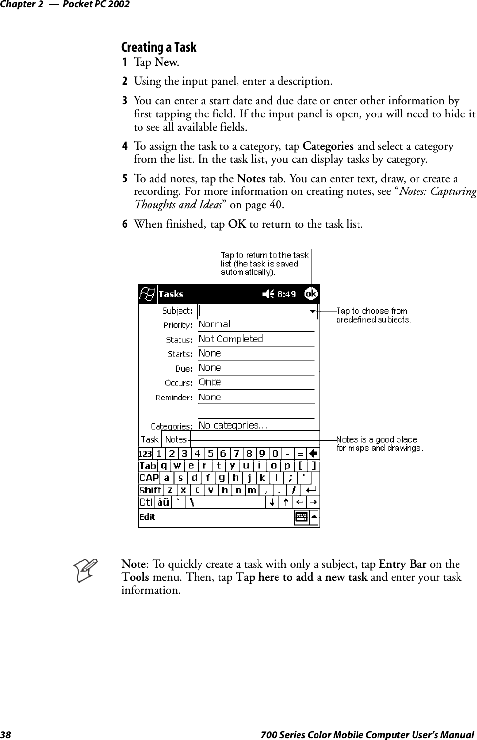
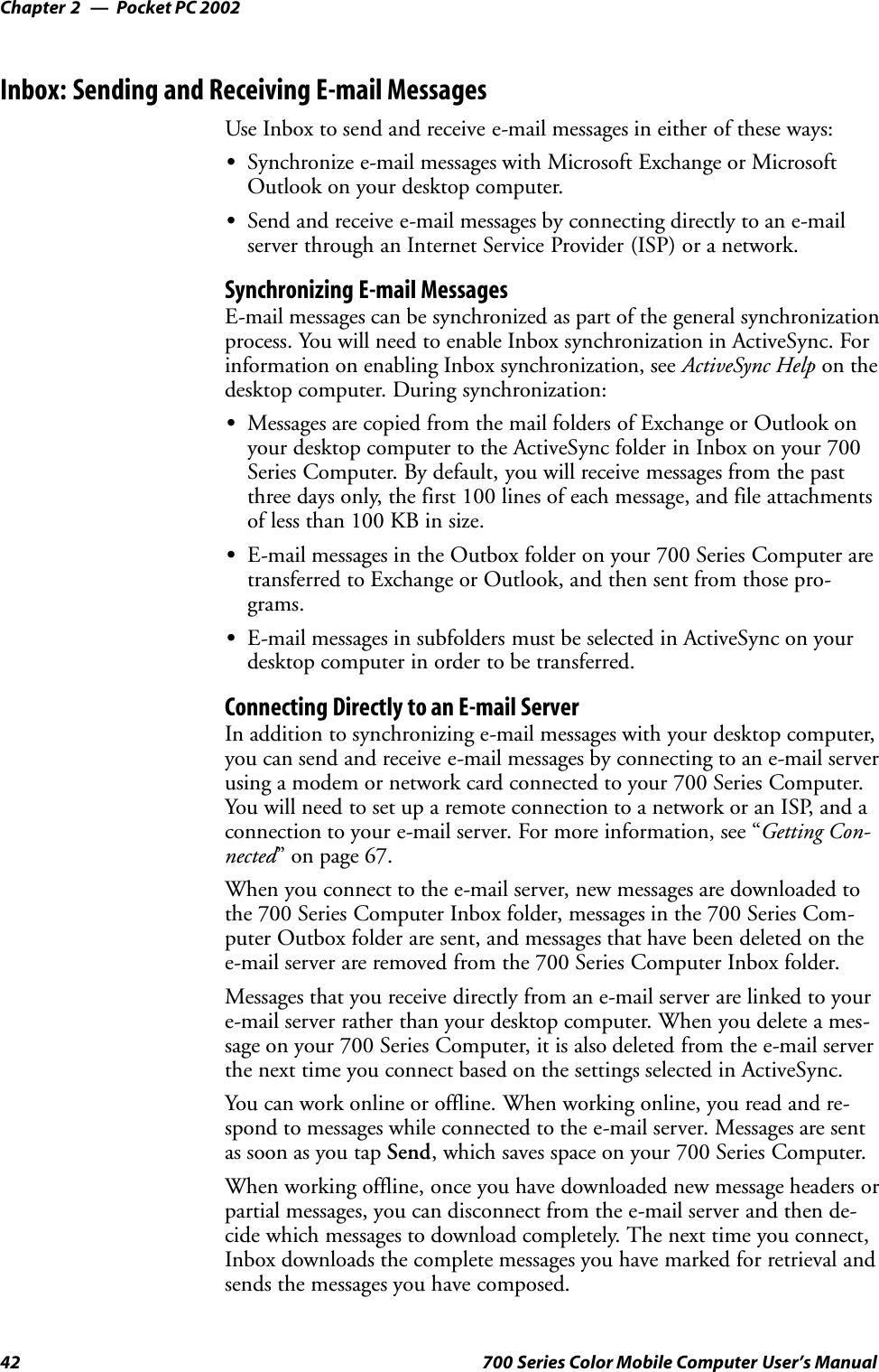
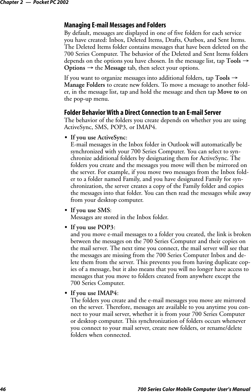
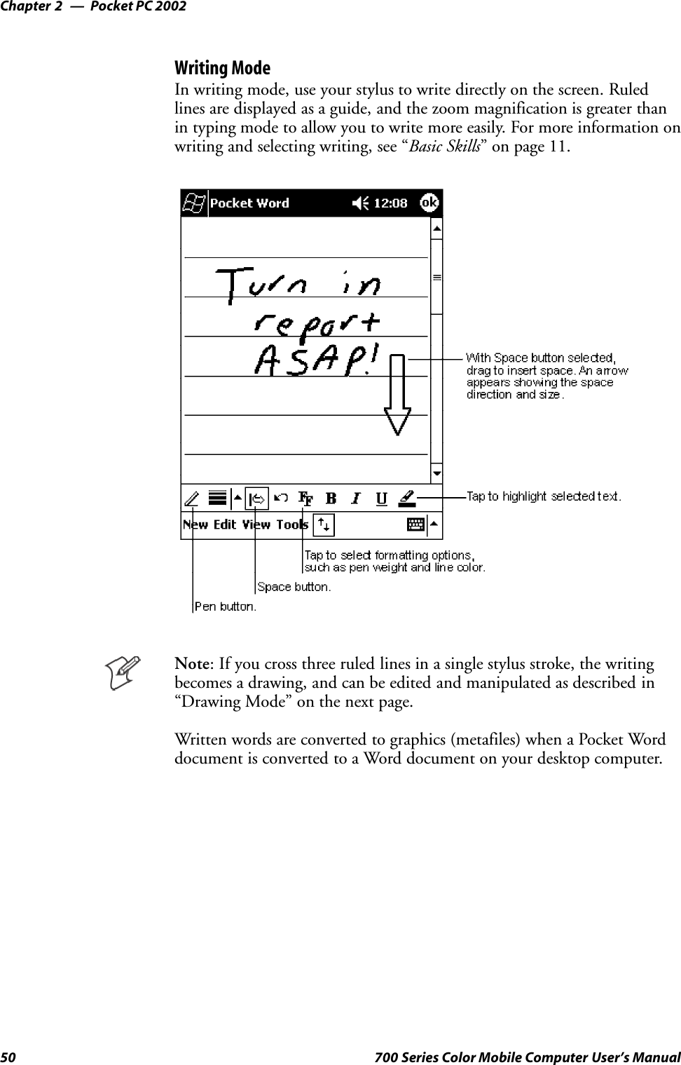
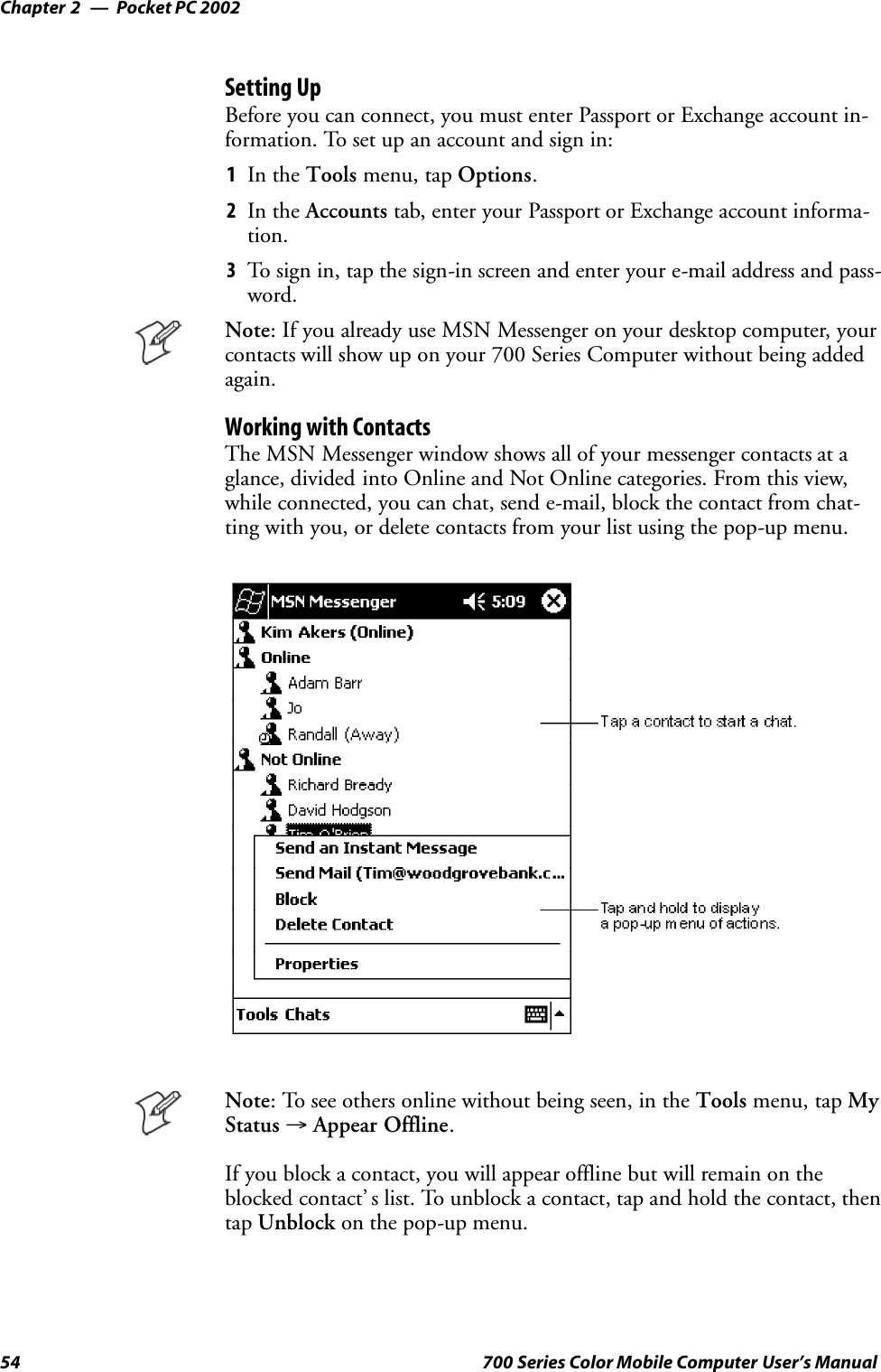
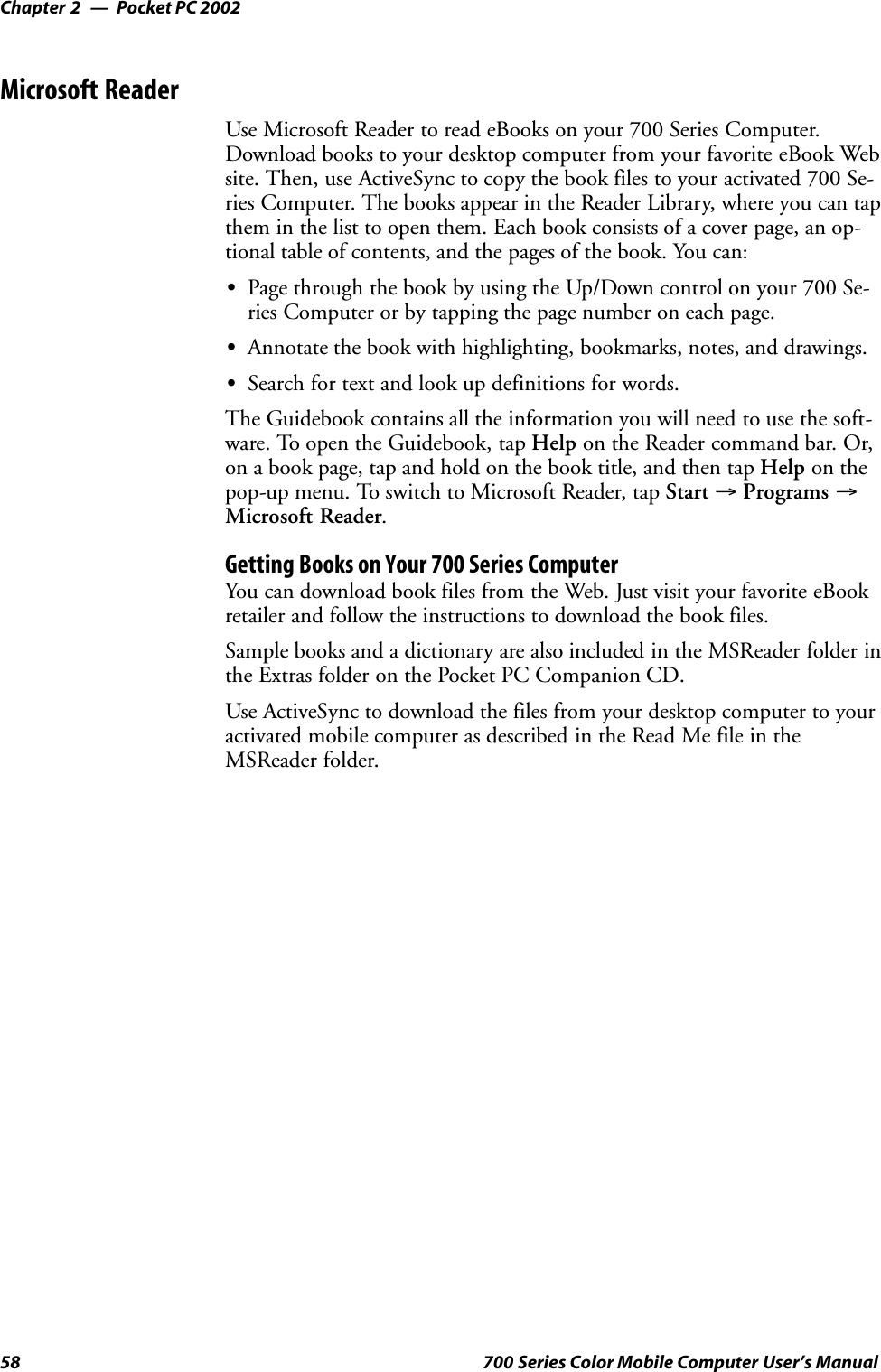
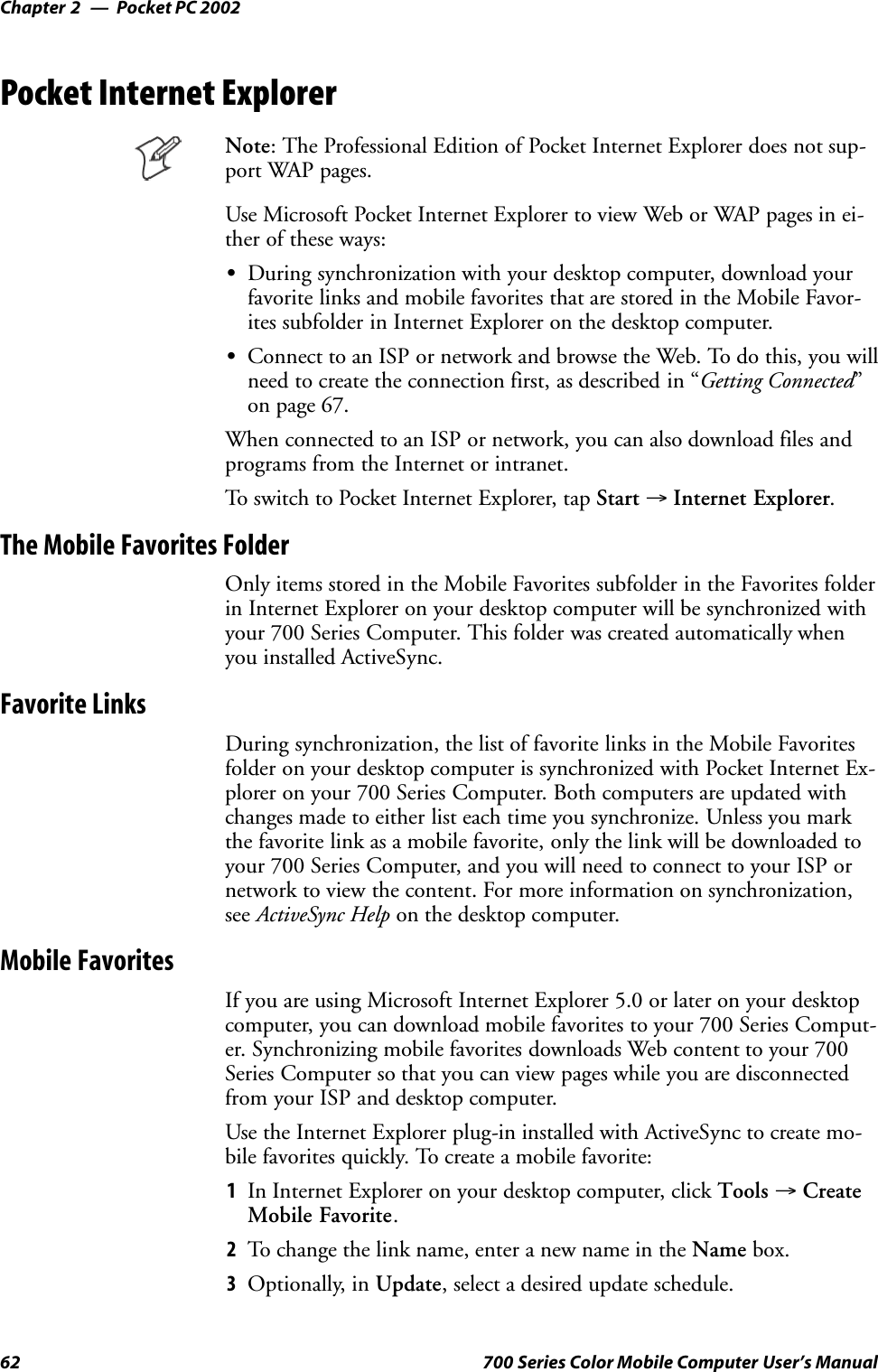
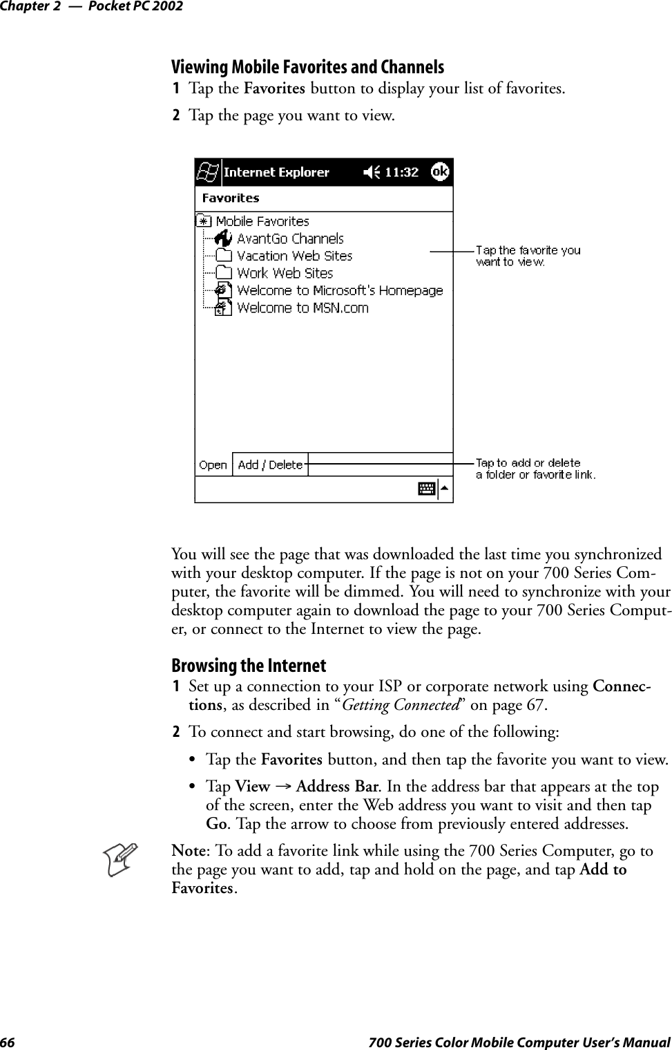
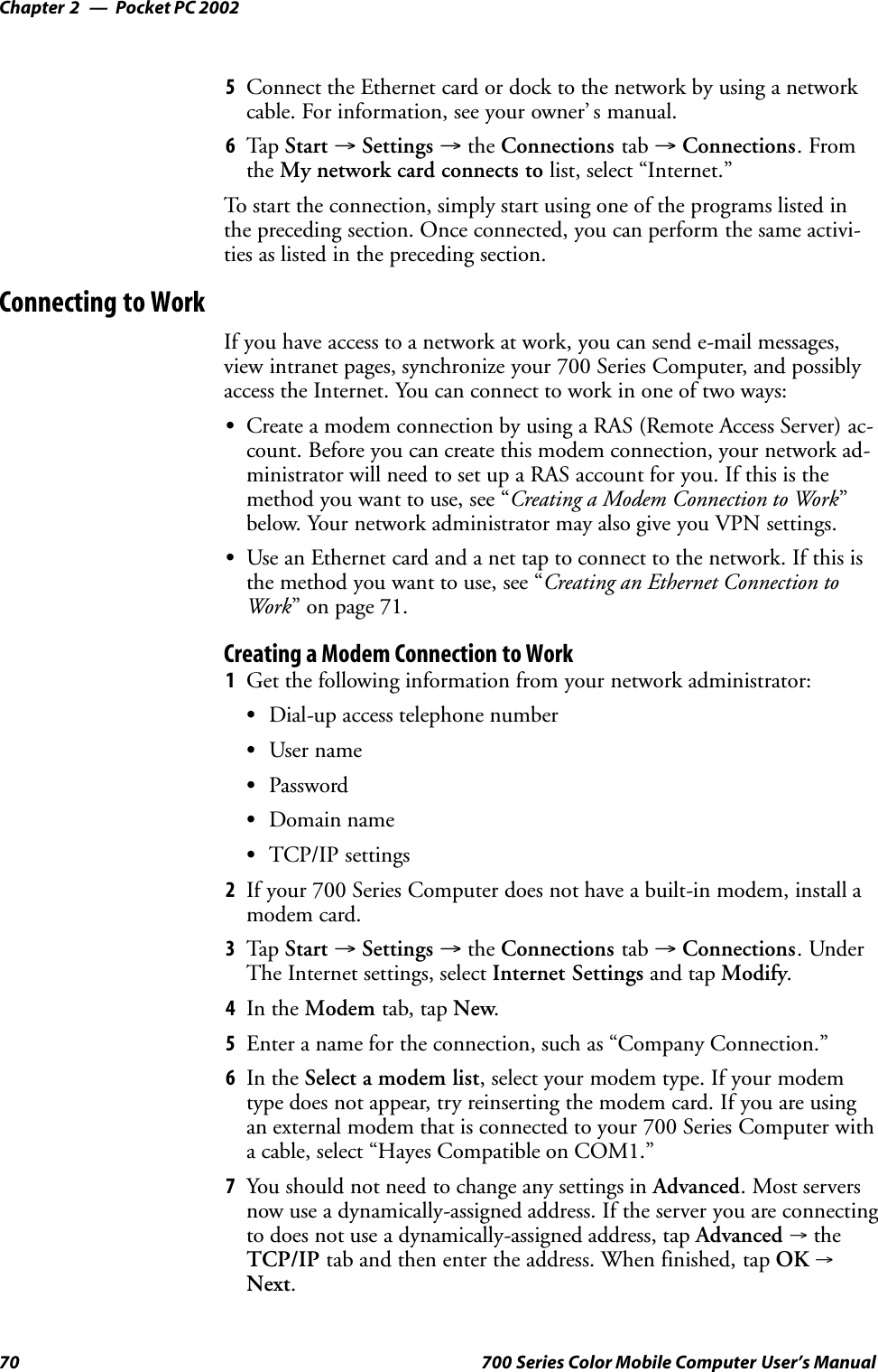
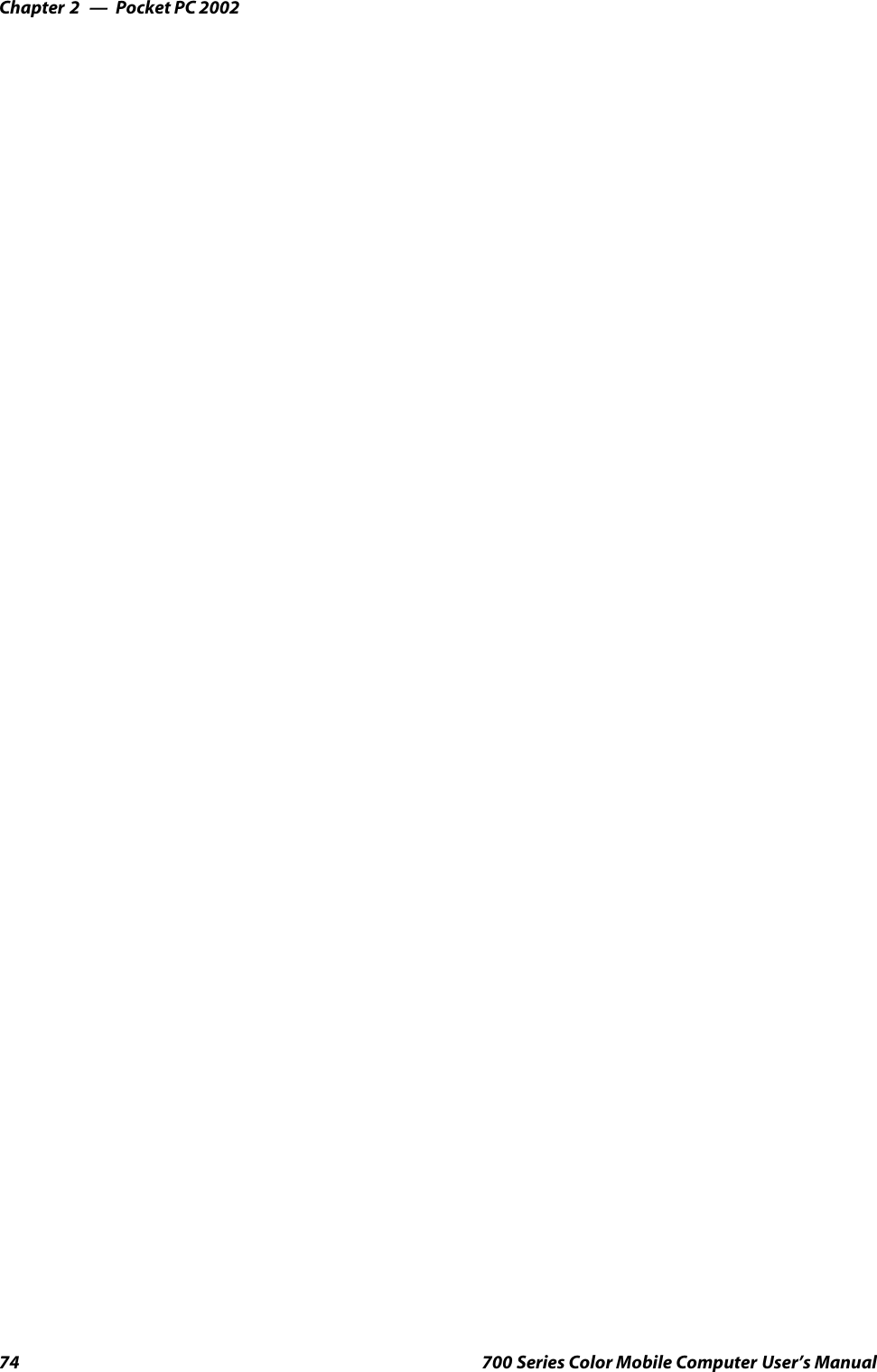
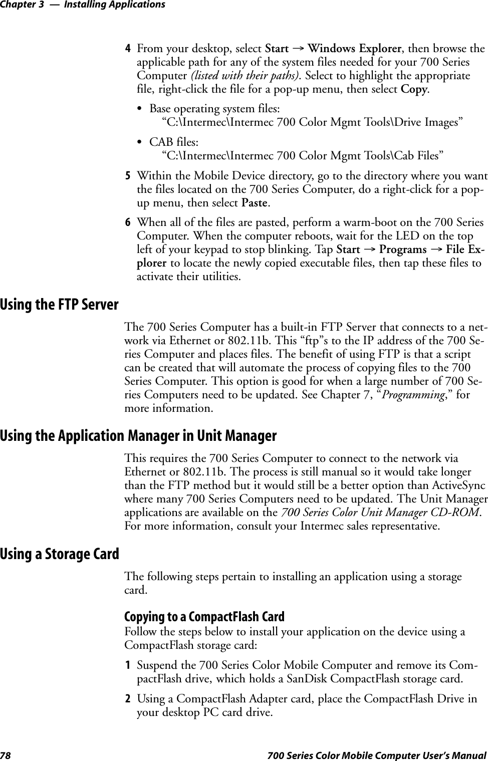
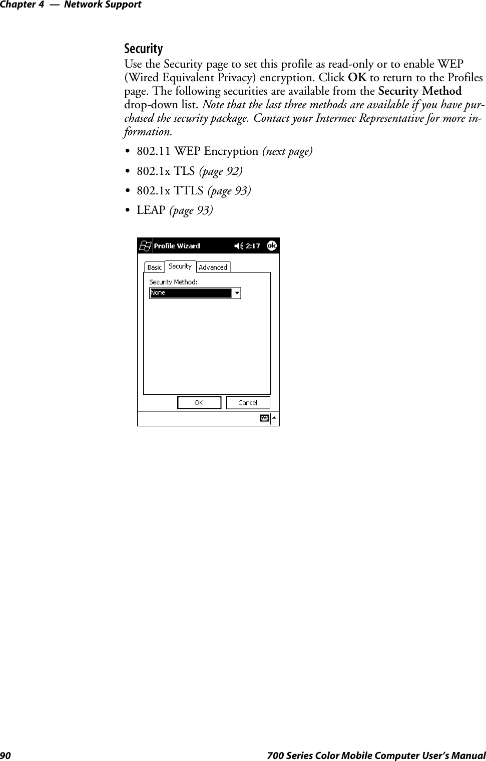
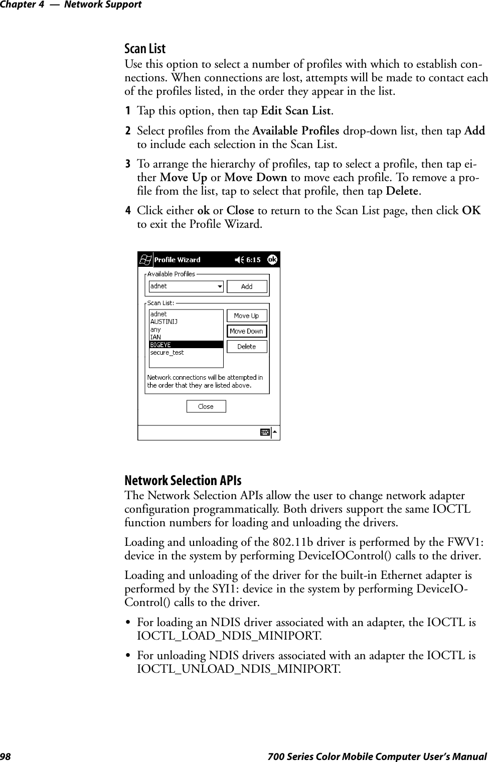
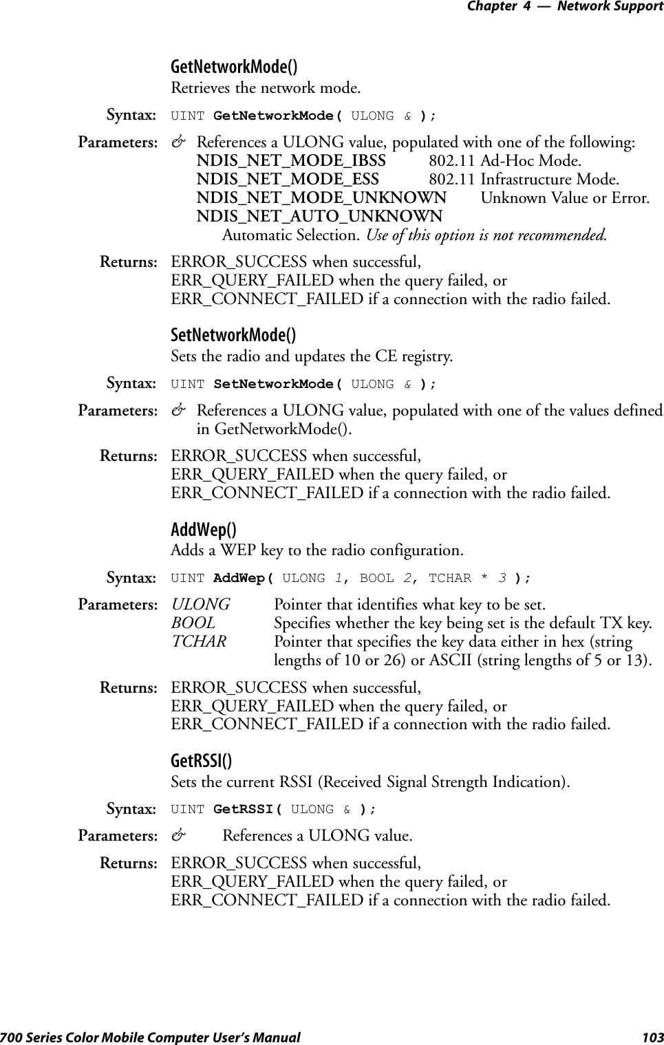
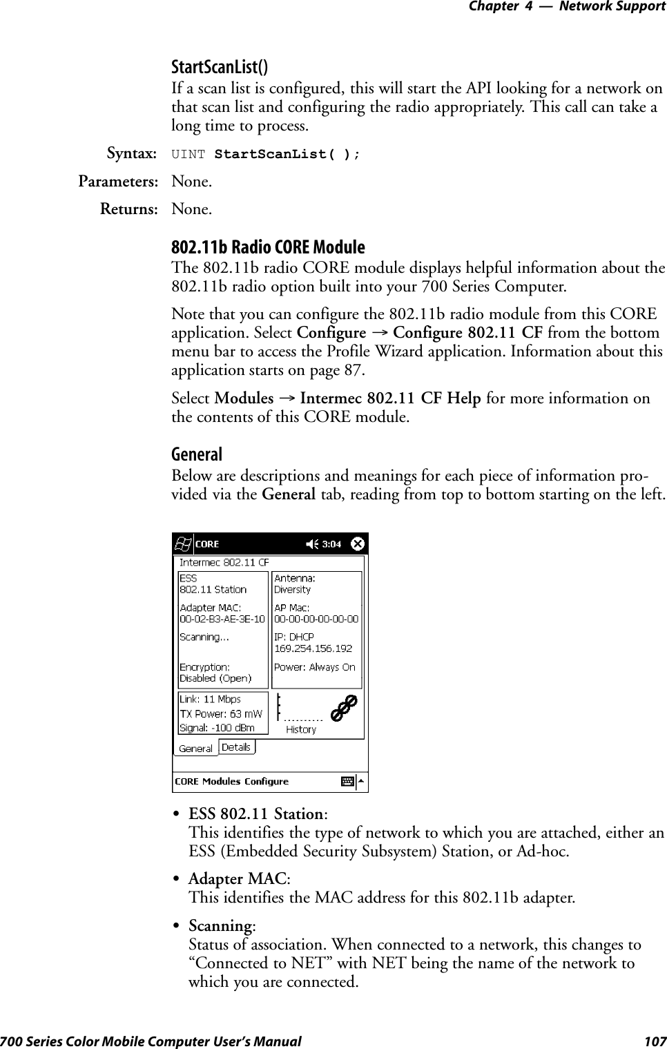
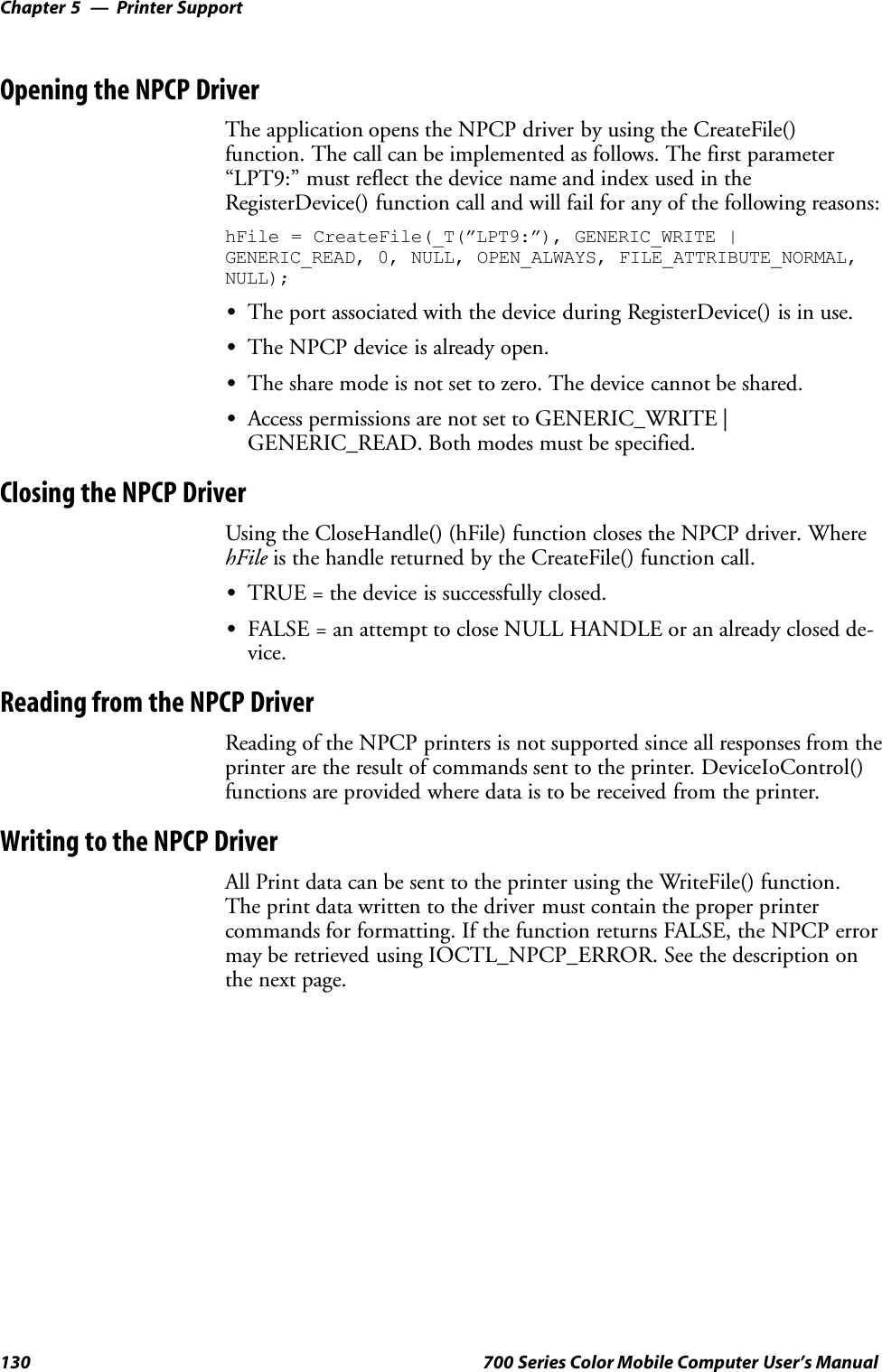
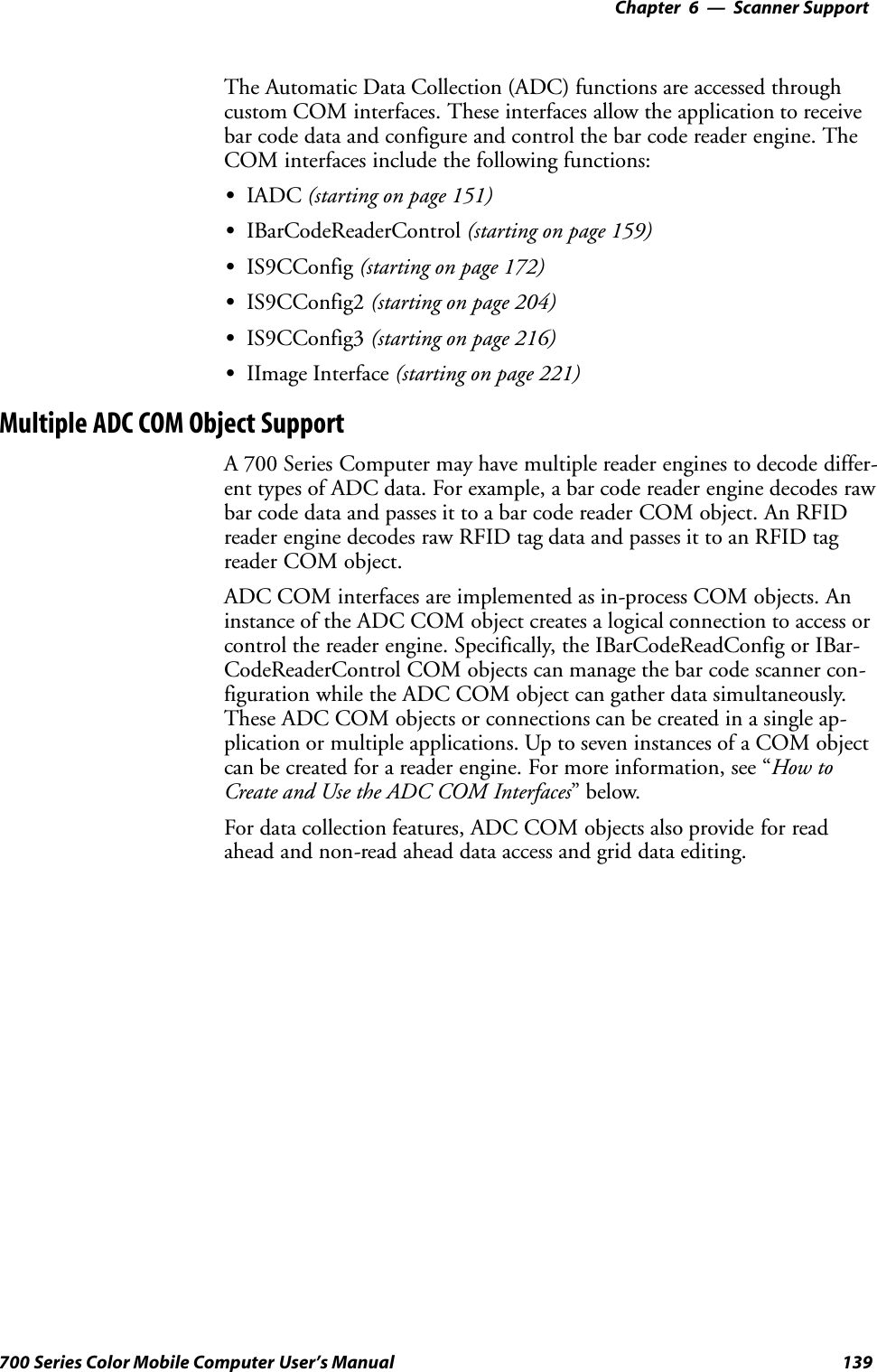
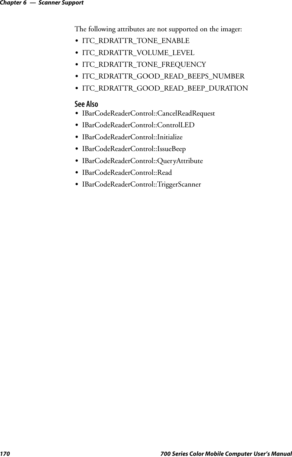
![Printer Support—Chapter 5129700 Series Color Mobile Computer User’s ManualNPCP Printer DriverThe NPCP printer communications driver (NPCPPORT.DLL) is aStream Device Driver built into the operating system. The driver supportsonly NPCP communications to and from the 6820 and 4820 printers overa selected serial port.All applications use WIN32 API functions to access the drivers. Basic op-erations are easily implemented by applications through the CreateFile(),WriteFile(), ReadFile(), DeviceIOControl(), and CloseHandle() Win32APIs.Operations to upgrade printer modules, perform printer diagnostics, andget printer configuration are performed largely via DeviceIOControl()functions.About NPCPNPCP (NorandPortable Communications Protocol) is a proprietary pro-tocol that provides session, network, and datalink services for Intermecmobile computers in the Intermec LAN environment used with printersand data communications.NPCP Driver Installation and RemovalUse LPT9: for the NPCP printer device and COM1 for the last parameter.COM1 is the connection available via the 700 Series Computer.Applications use the RegisterDevice() function to install the driver.DeregisterDevice() uninstalls the device driver and frees memory spacewhen the driver is not required. Use the HANDLE returned byRegisterDevice() as the parameter to DeregisterDevice().Use the RegisterDevice() function call as demonstrated below. Specify thefull path name to the driver starting at the root for the RegisterDevice()function to work properly. The last parameter to RegisterDevice() is aDWORD that represents the name of the port for the NPCP stream driverto use. Build this parameter on the stack if it is not to be paged out duringthe call. The first parameter “LPT” (Device Name) and the secondparameter “9’ (index), indicate the name of the registered device, such asLPT9. This is used in the CreateFile() function call.Install(){HANDLE hDevice;TCHAR port[6];port[0] = TCHAR(‘C’);port[1] = TCHAR(‘O’);port[2] = TCHAR(‘M’);port[3] = TCHAR(‘1’);port[4] = TCHAR(‘:’);port[5] = TCHAR(0);hDevice = RegisterDevice ( (TEXT(”LPT”), 9,TEXT(“\\STORAGE CARD\\WINDOWS\\NPCPPORT.dll”), (DWORD)port);}](https://usermanual.wiki/Intermec-Technologies/SB555.Item-5-from-FCC-email-Feb-07-2003/User-Guide-307179-Page-146.png)
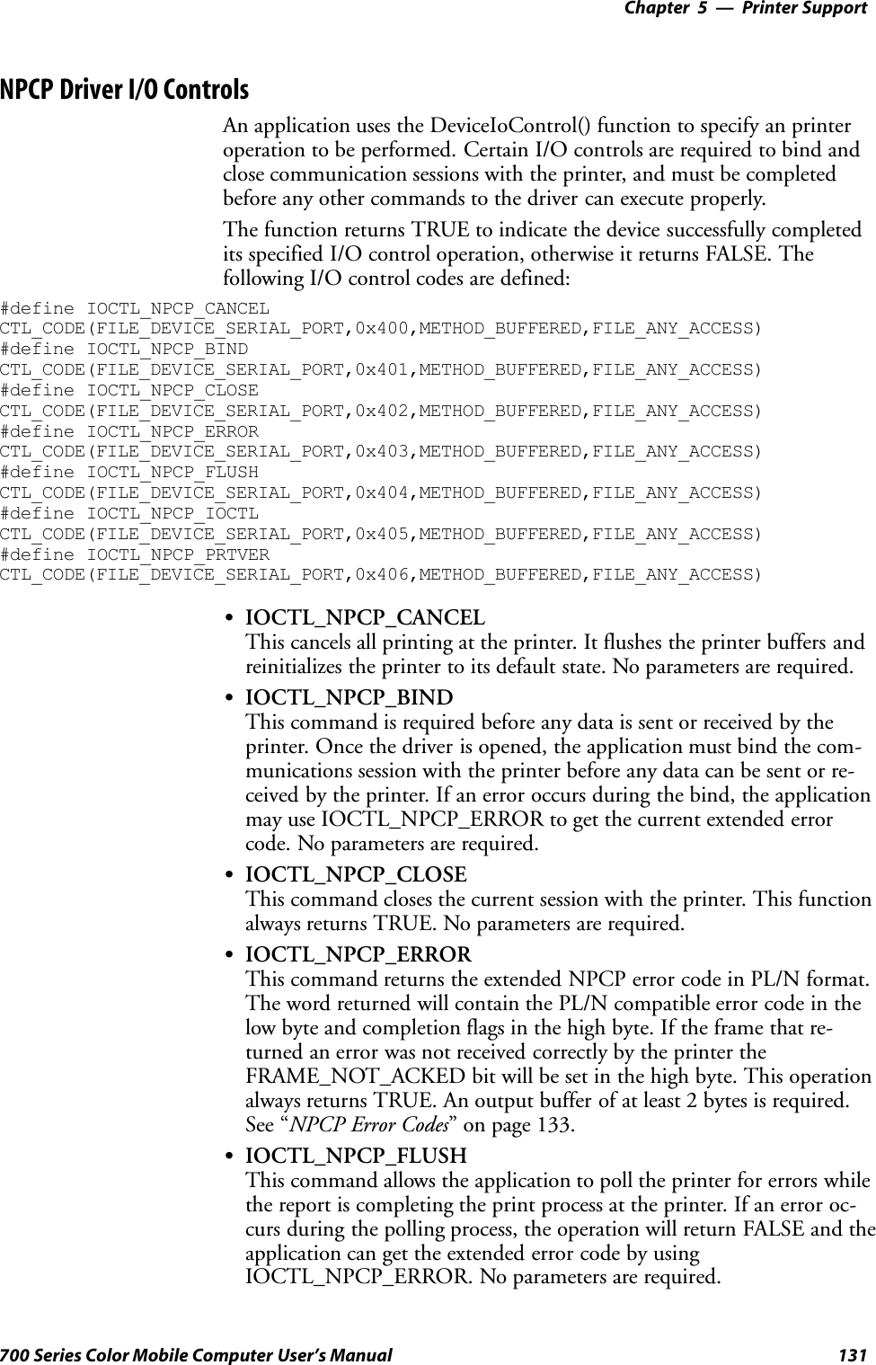
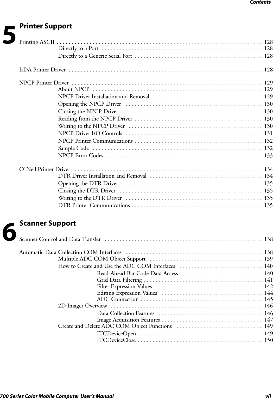
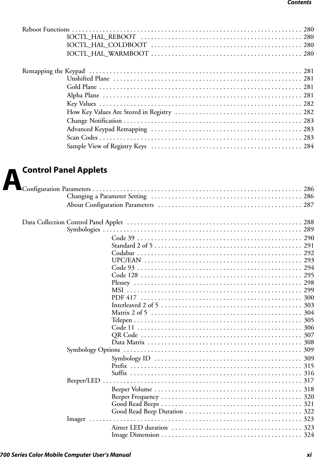
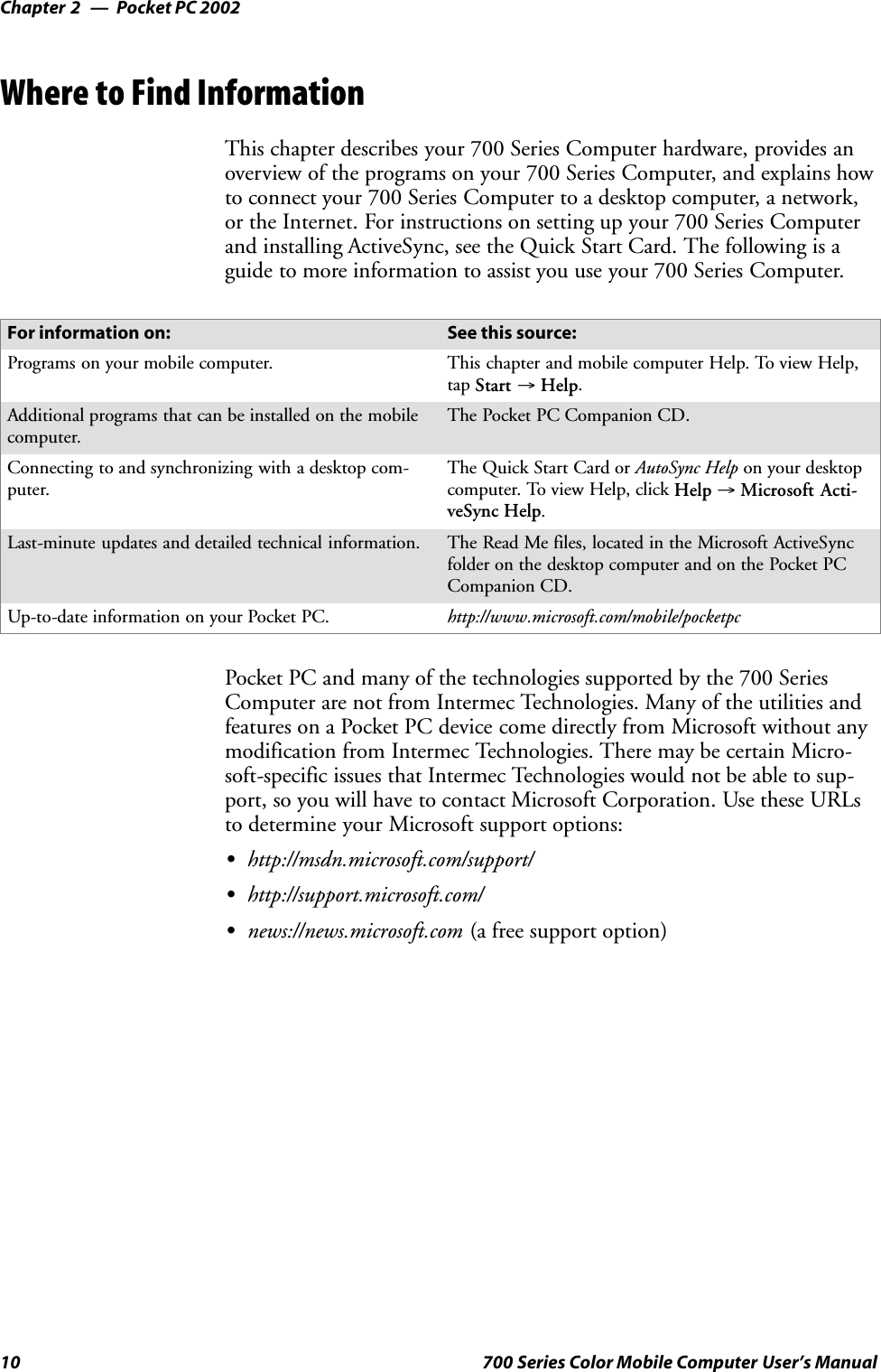
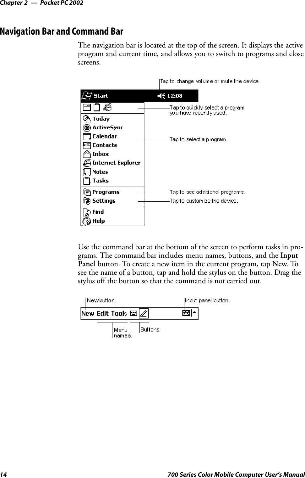
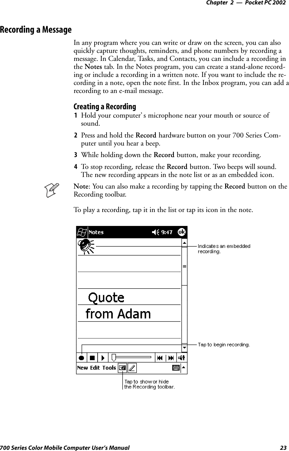
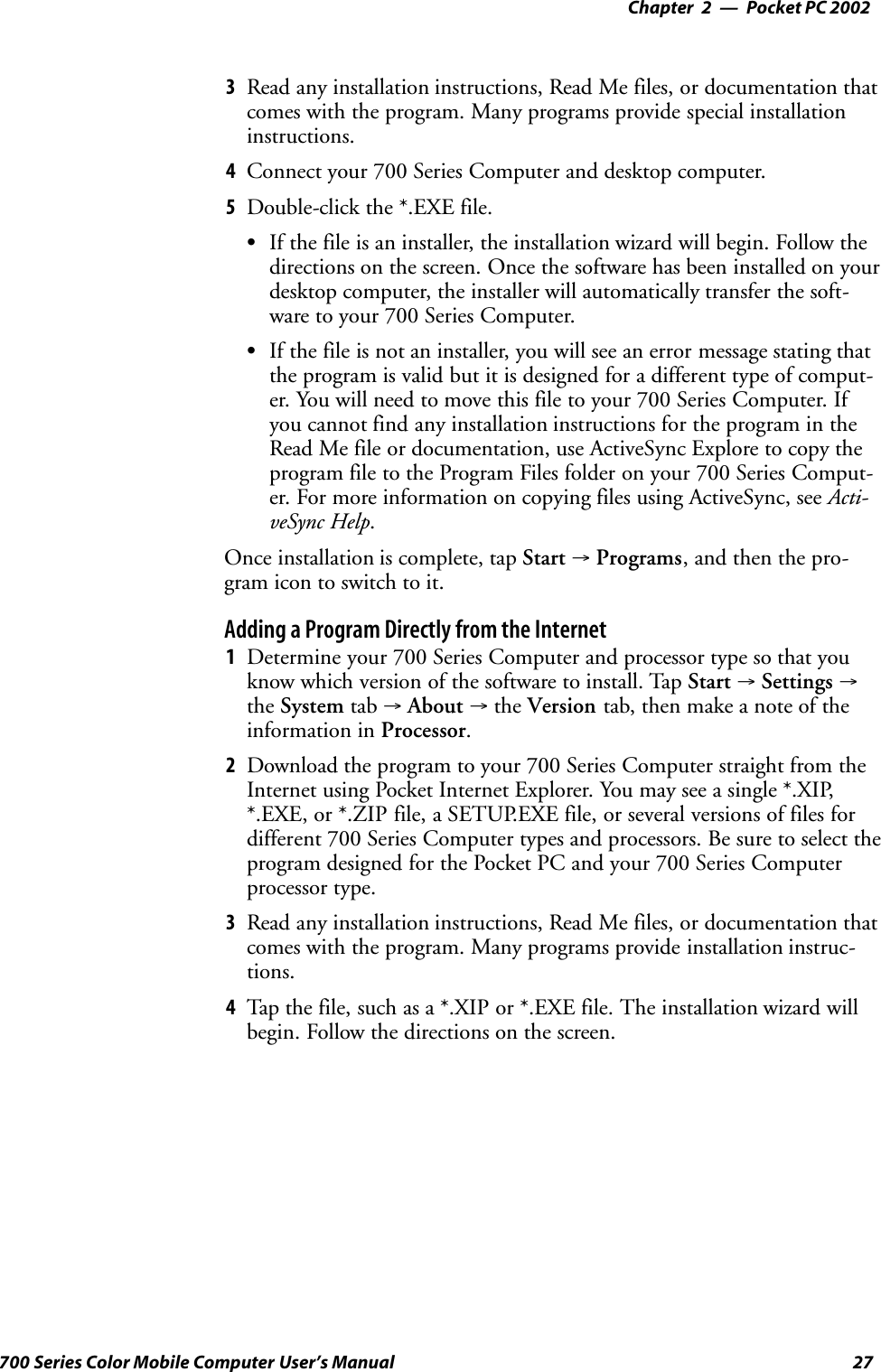
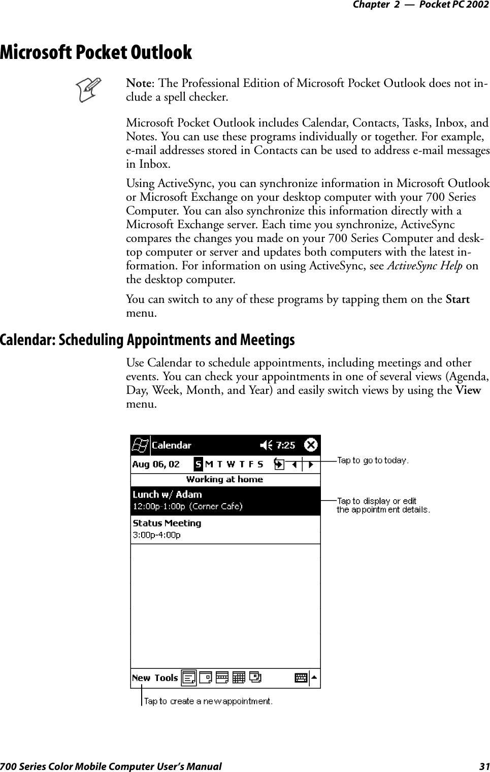
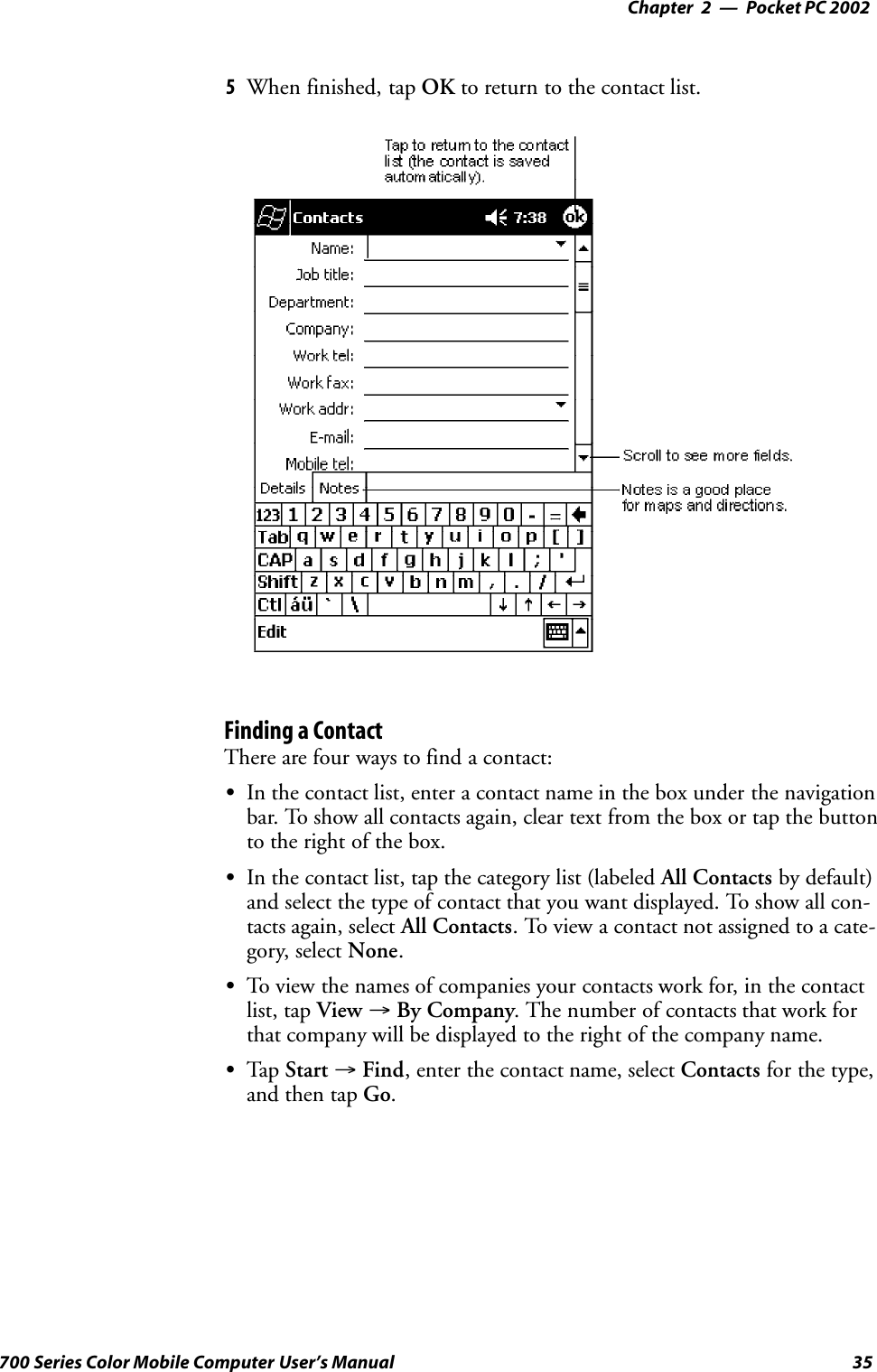
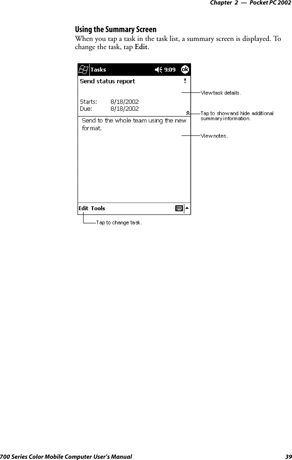
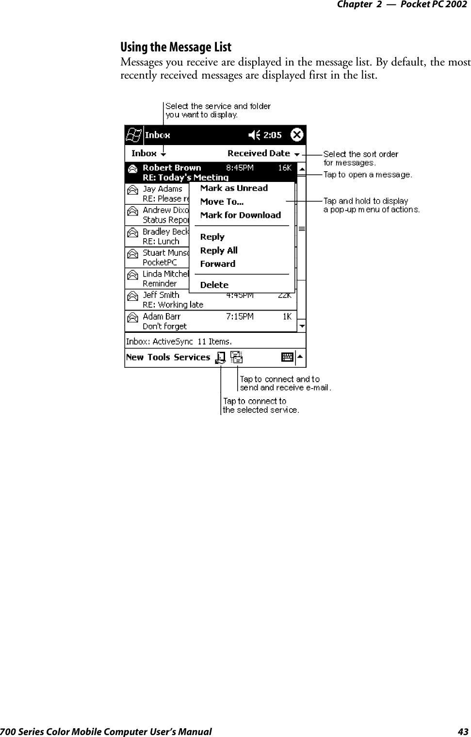
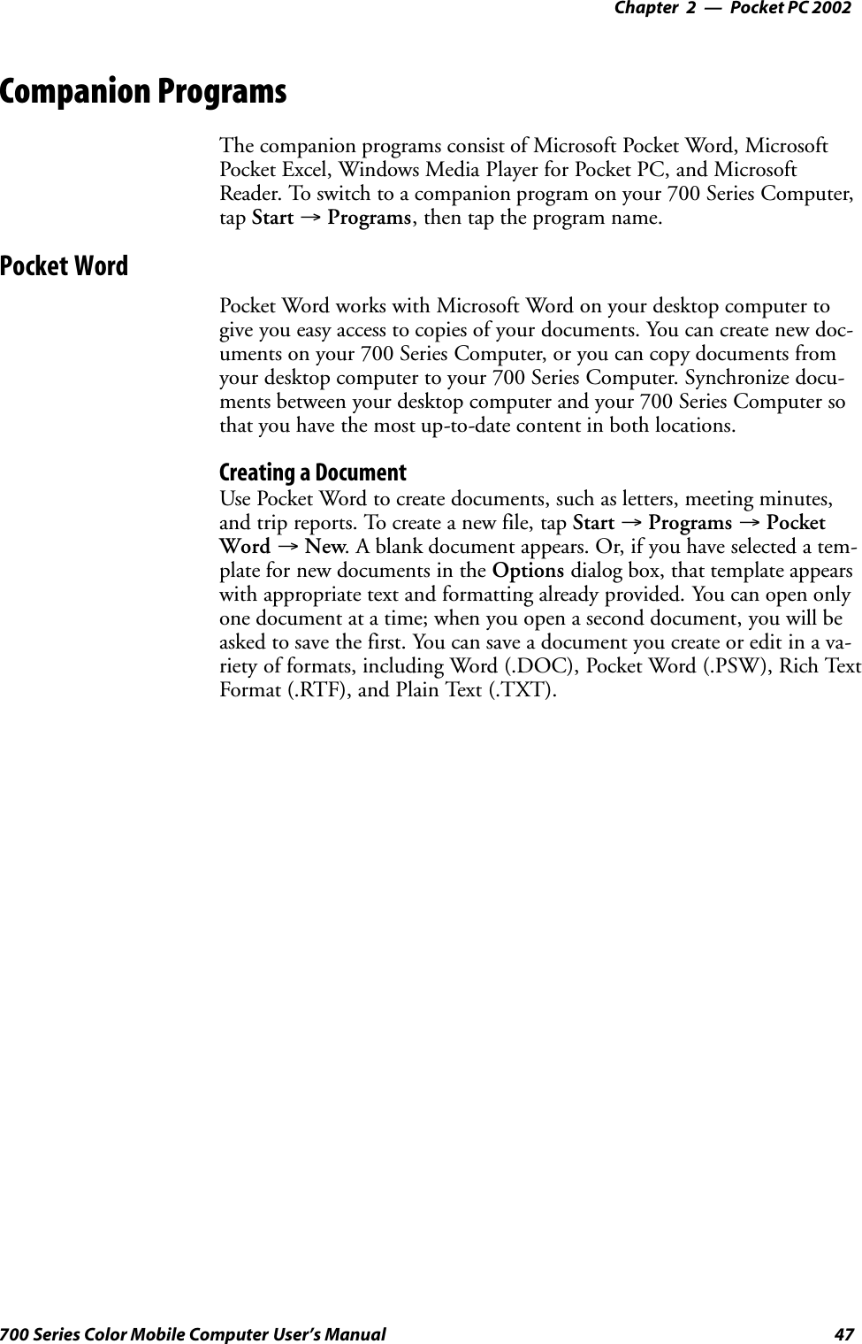
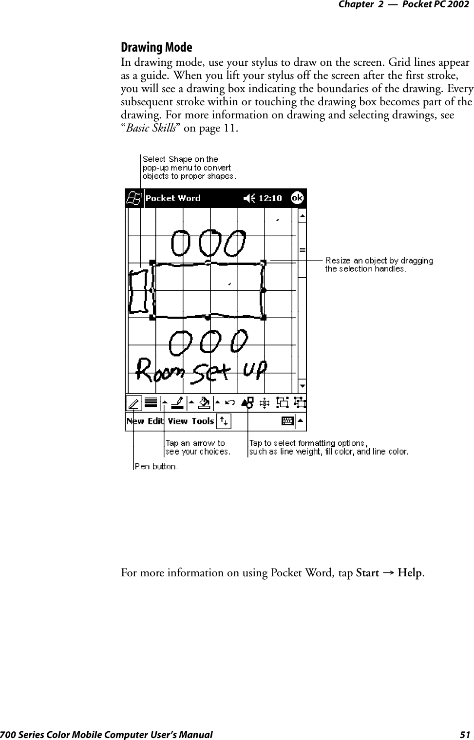
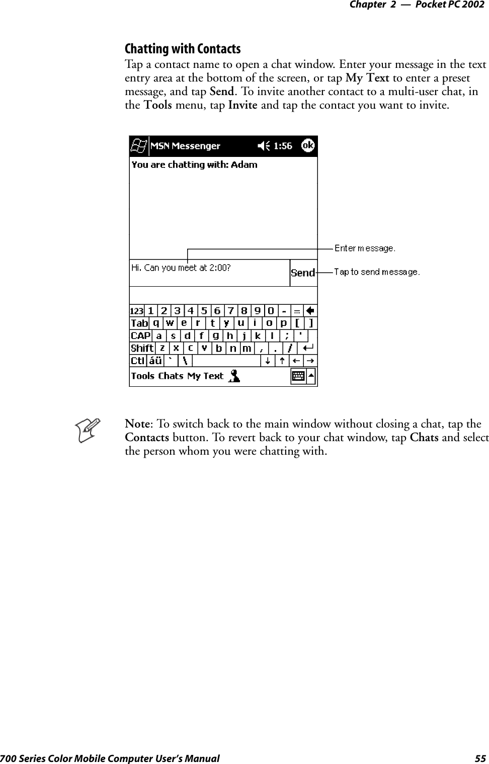
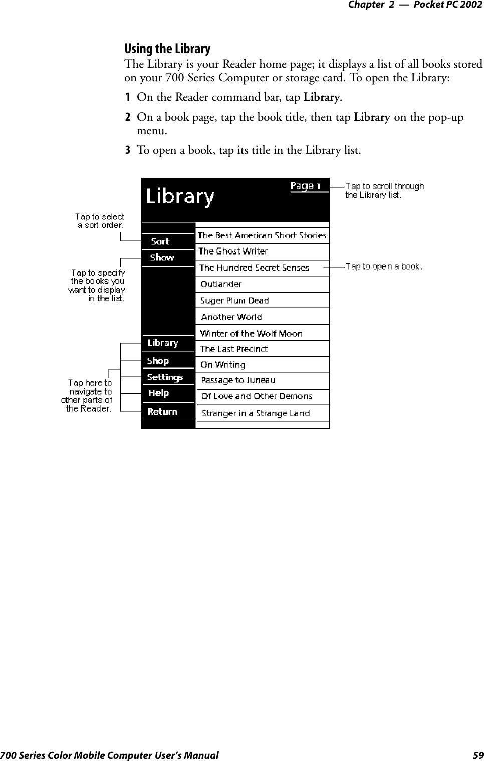
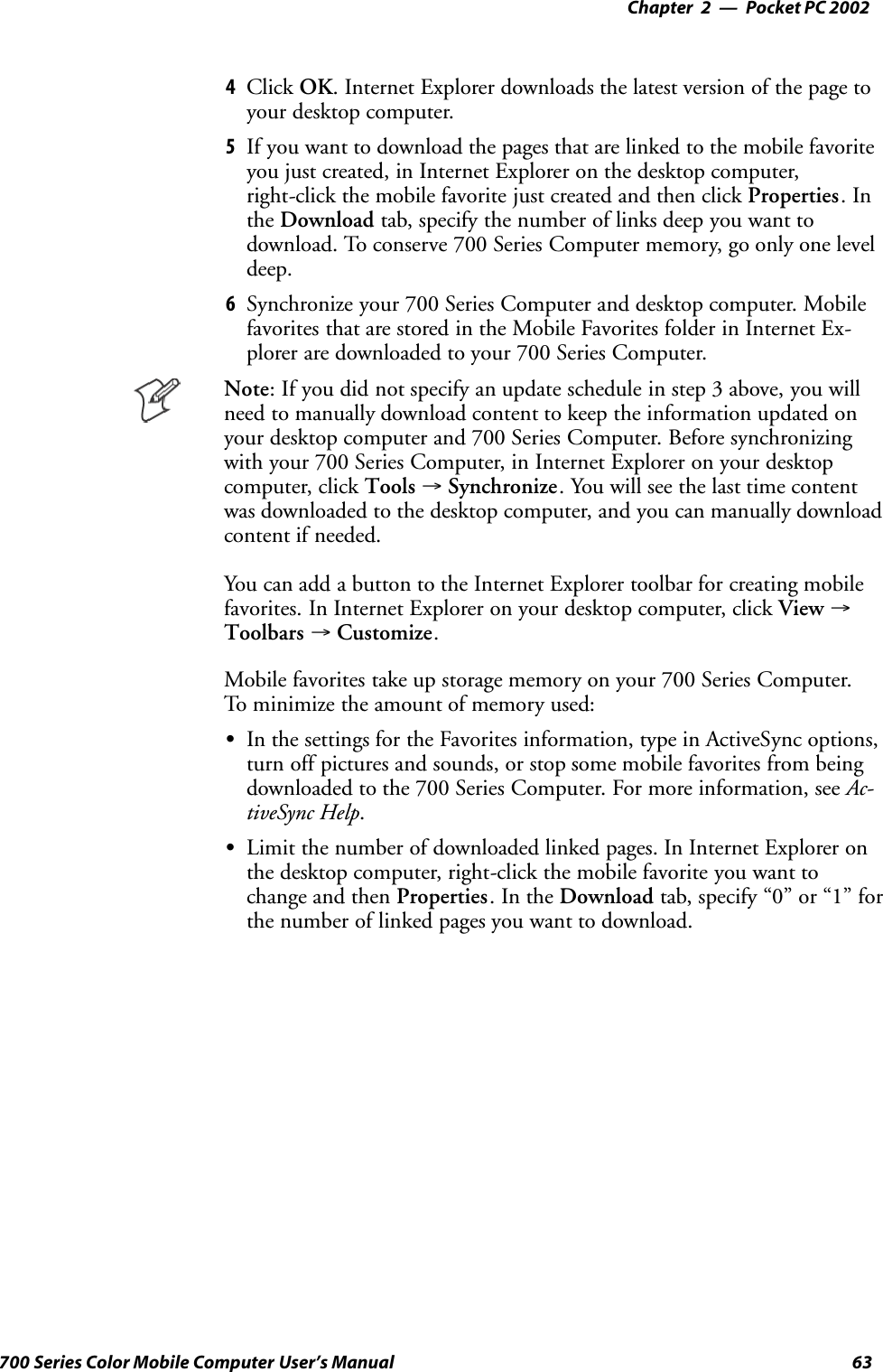
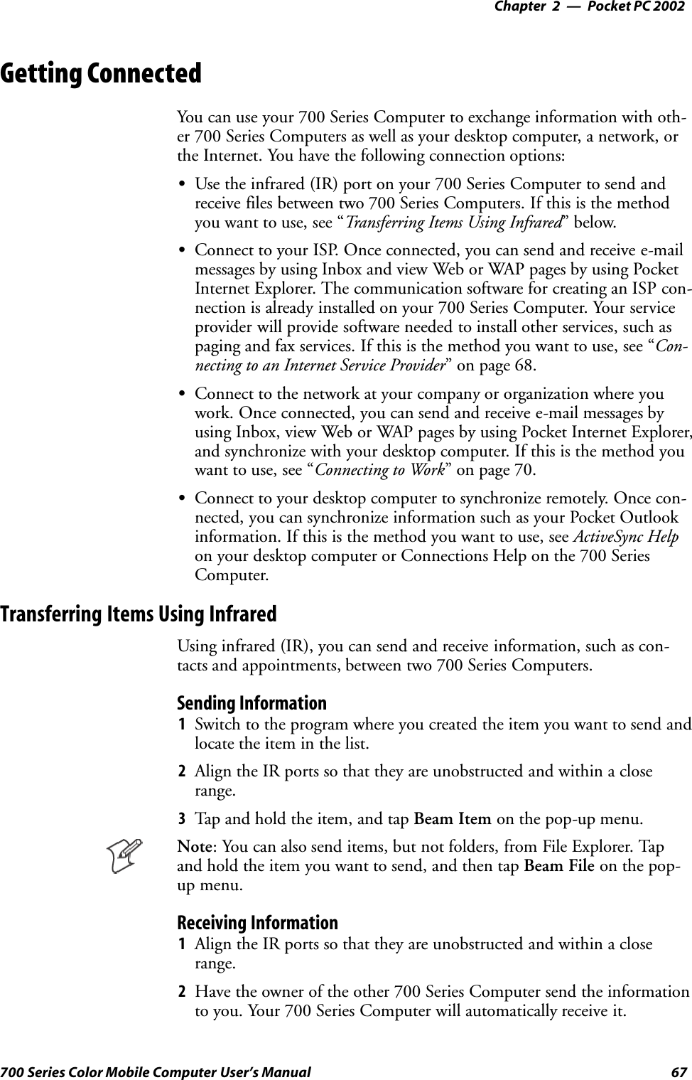
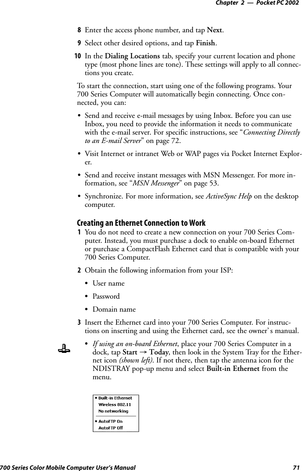
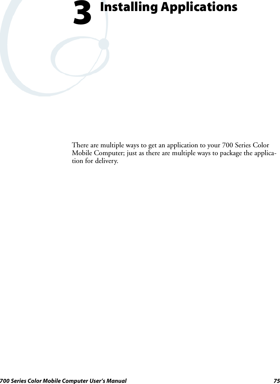
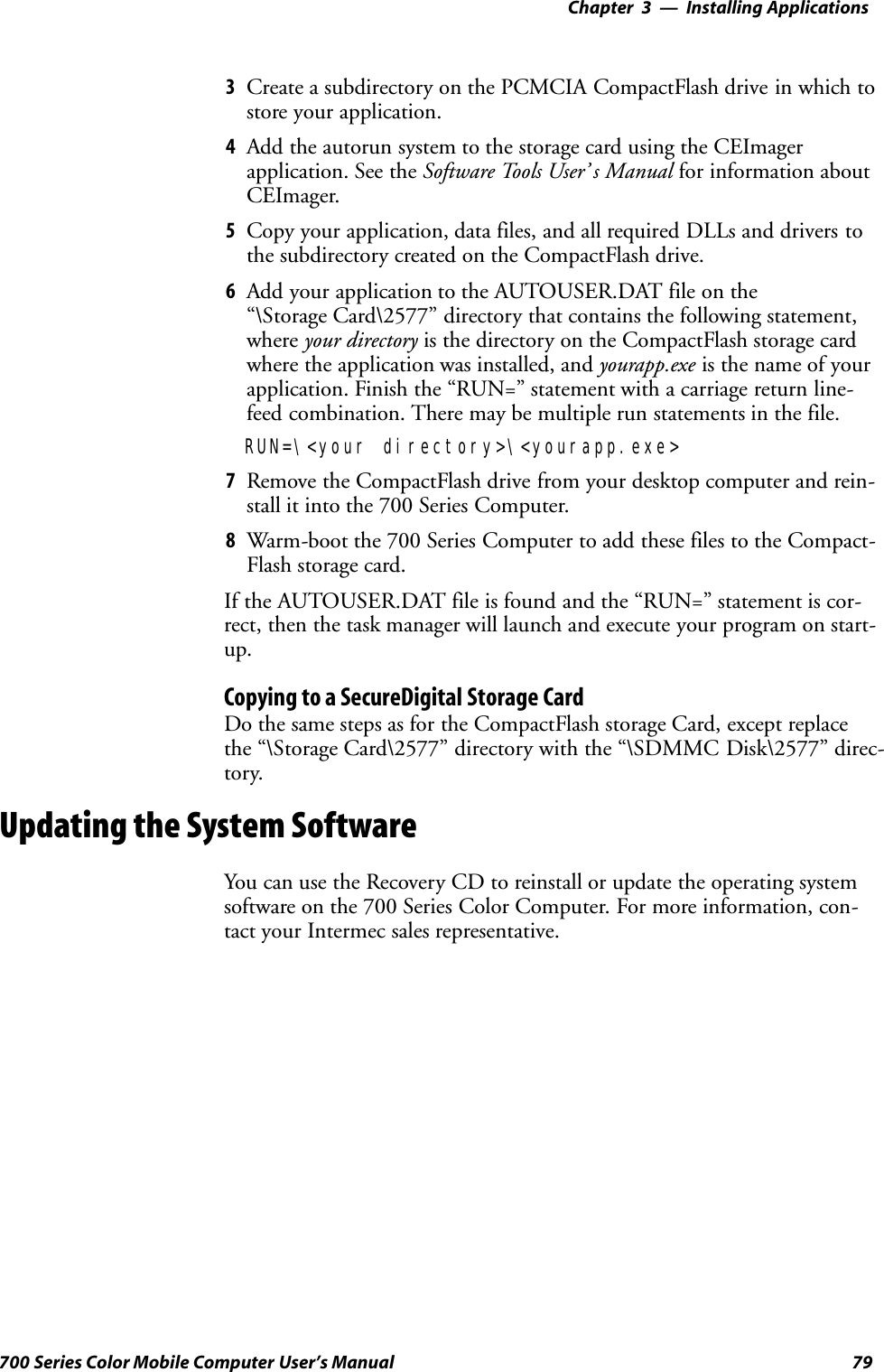
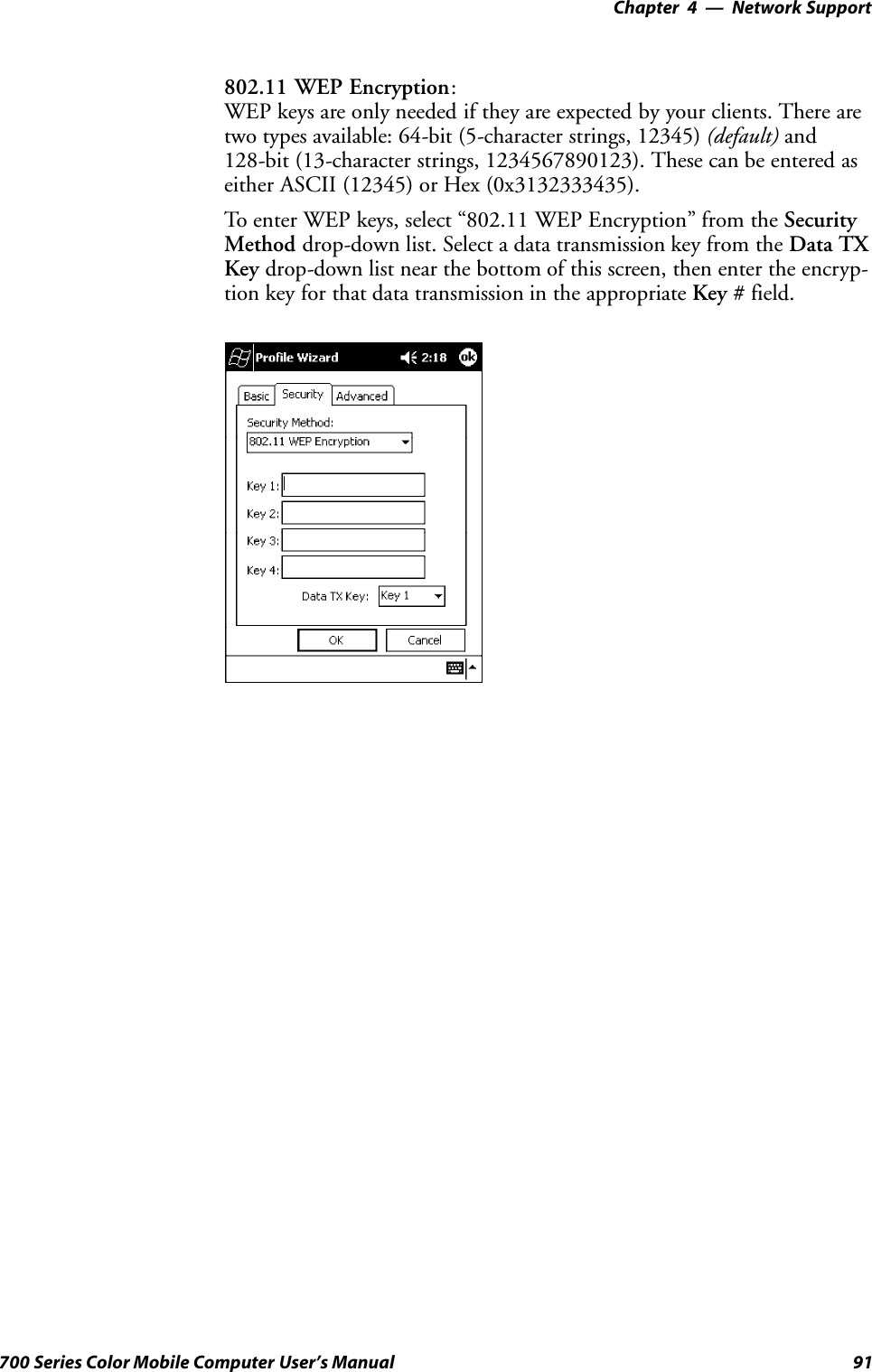
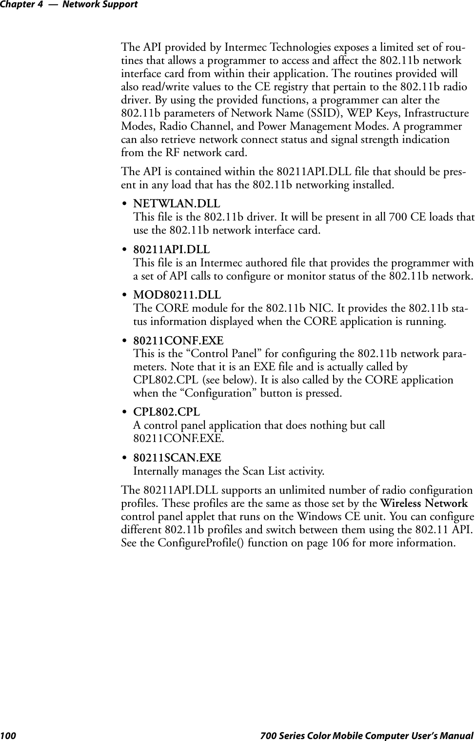
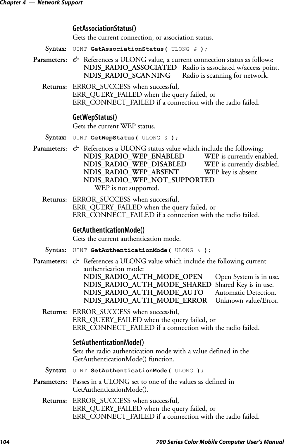
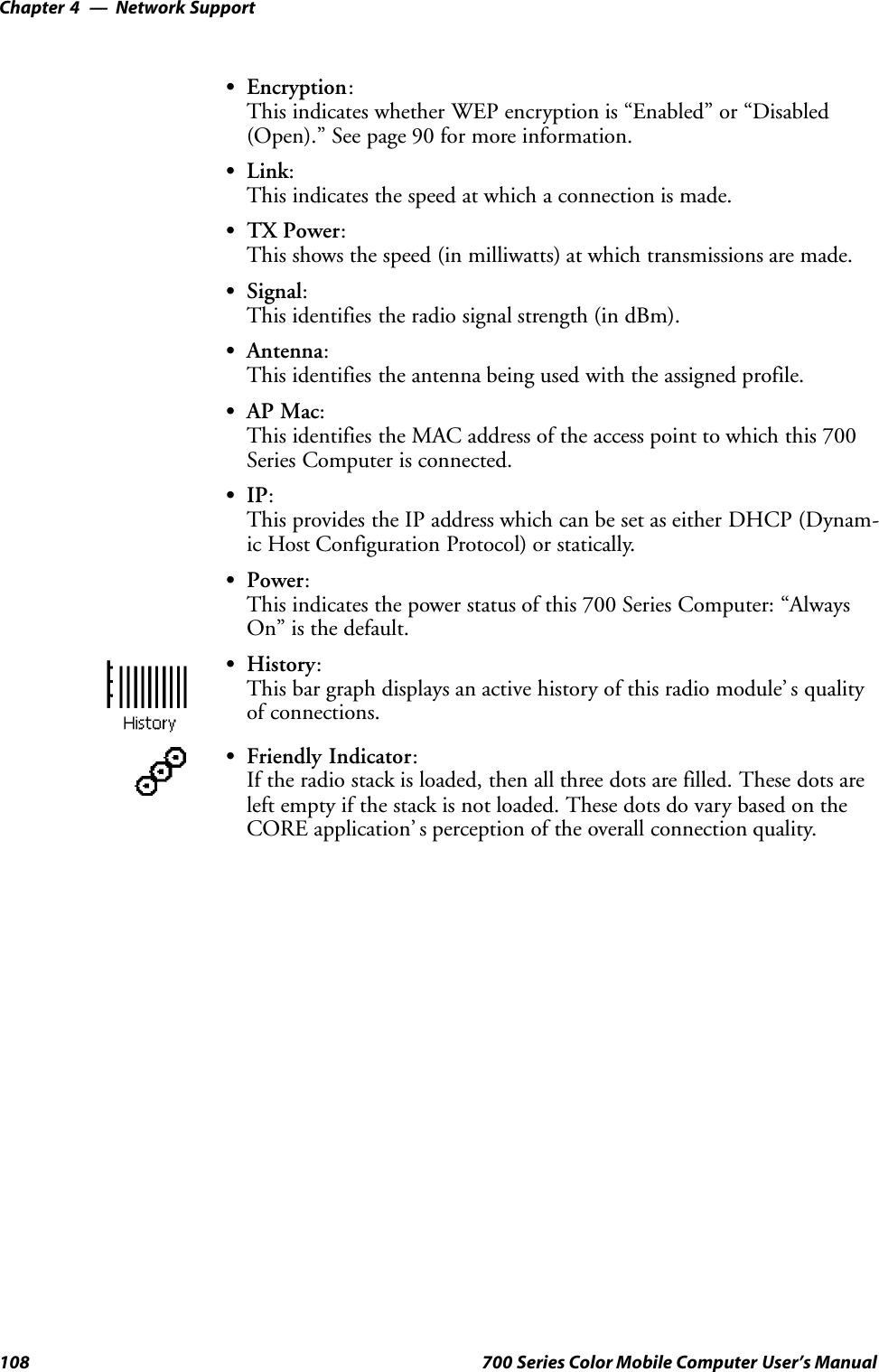
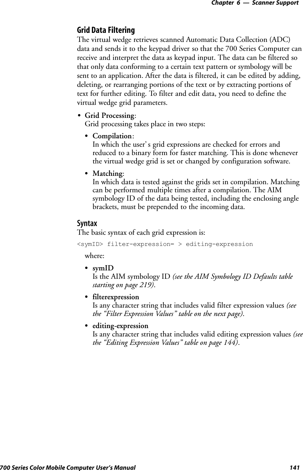
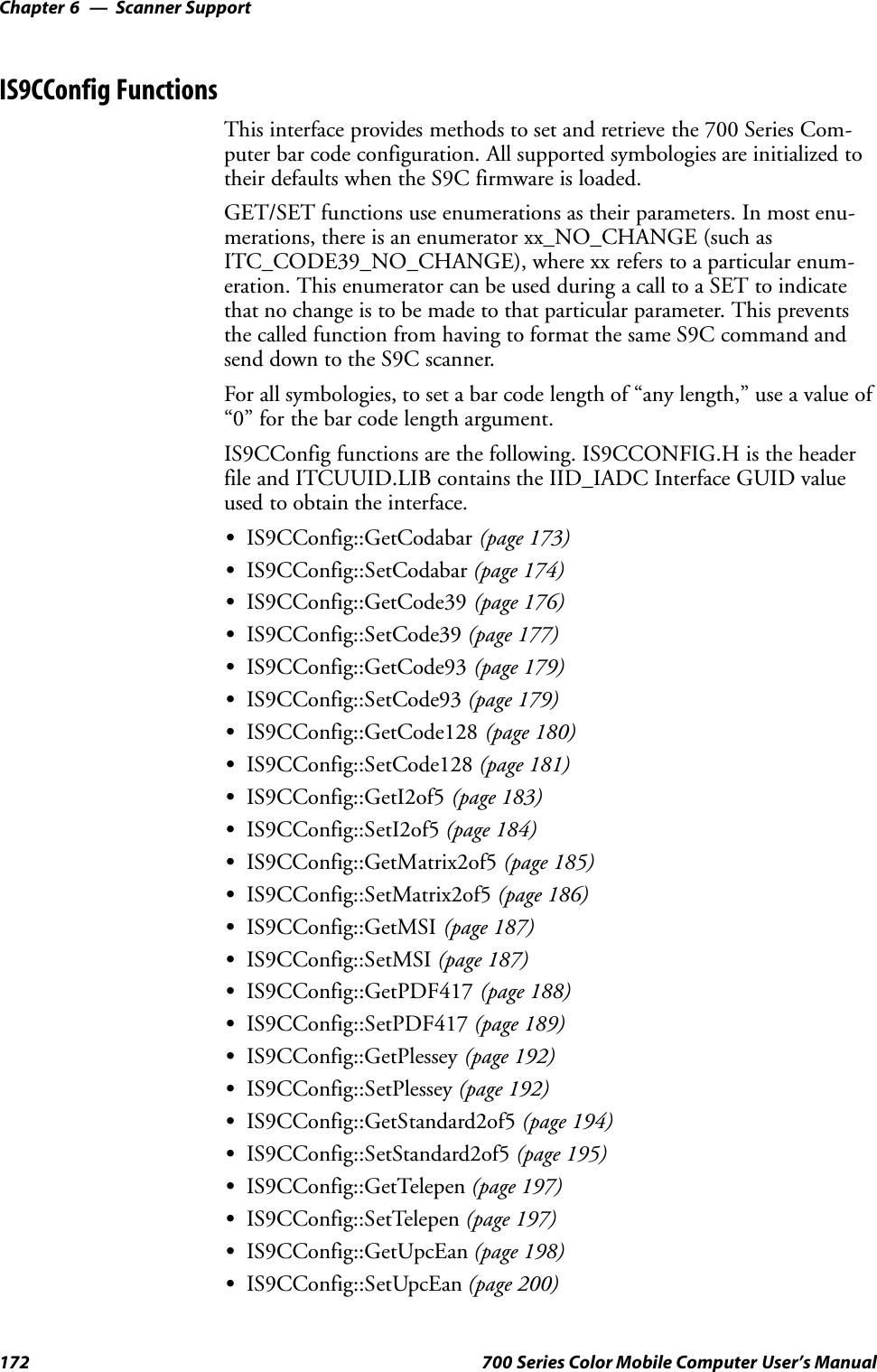
![Printer SupportChapter —5134 700 Series Color Mobile Computer User’s ManualO’Neil Printer DriverThe DTR printer communications driver is a Stream Device Drivernamed ONEIL.DLL.All applications use WIN32 API functions to access drivers. Basicoperations are easily implemented by applications through the CreateFile(),WriteFile(), DeviceIOControl() and CloseHandle() Win32 APIs.The driver supports communications to 6804DM, 6804T, 6805A, 6806,6808, 681T, and 781 printers over a selected serial port.DTR Driver Installation and RemovalYour application must install the device driver by using the RegisterDe-vice() function. The driver name is ONEIL.DLL. We recommend thatyou use “DTR” for the Device Name parameter, “1” for the Device Driverindex parameter, and use any of the following strings for the last parame-ter:SNULL (==0) Defaults to COM1 @ 9600S“COM1” only COM port specified defaults to 9600S“COM1:9600” sets to COM port and specified bit rateS“COM1:19200” sets to COM port and specified bit rateUse the HANDLE returned by RegisterDevice() as the parameter toDeregisterDevice(). The correct usage of the RegisterDevice() function callis demonstrated below. You may use DeregisterDevice() to uninstall thedriver.Install(){HANDLE hDevice;TCHAR port[6];port[0] = TCHAR(‘C’);port[1] = TCHAR(‘O’);port[2] = TCHAR(‘M’);port[3] = TCHAR(‘1’);port[4] = TCHAR(‘:’);port[5] = TCHAR(0);hDevice = RegisterDevice ( (TEXT(”DTR”), 1, TEXT(”\\WINDOWS\\ONEIL.DLL”),(DWORD)port);}](https://usermanual.wiki/Intermec-Technologies/SB555.Item-5-from-FCC-email-Feb-07-2003/User-Guide-307179-Page-151.png)
![Scanner SupportChapter —6140 700 Series Color Mobile Computer User’s ManualHow to Create and Use the ADC COM InterfacesYou can also use the Input Device Functions (starting on page 149) tocreate and use the ADC COM interfaces.1Create and initialize the in-process Bar Code Reader object usingITCDeviceOpen() (see page 149). This function returns a COMInterface pointer to the Bar Code Reader Object created by thefunction.2Set the data grid if data filtering is desired (default grid gives the applica-tion all the data). Below is a sample code of how to set the grid to acceptCode 39 data that starts with the letter “A” and is not a reader com-mand.ITC_BARCODEREADER_GRID stBCGrid;stBCGrid.stDIGrid.szDataMask = TEXT(”A%s”);stBCGrid.stDDGrid.dwSymbologyMask = BARCODE_SYMBOLOGY_CODE39;stBCGrid.dwDataSourceTypeMask = ITC_DATASOURCE_USERINPUT;HRESULT hrStatus = pIBCControl->SetAttribute(ITC_RDRATTR_GRID,reinterpret_cast<BYTE *>(&stBCGrid),sizeof(stBCGrid));3Issue a read to accept the bar code data. The timestamp, symbology, anddata type are put into the ITC_BARCODE_DATA_DETAILS struc-ture. Passing in a pointer to this structure is optional. The followingsample code uses an infinite timeout.ITC_BARCODE_DATA_DETAILS stBCDetails;BYTE rgbBCData[1024]; // Buffer used to accept the bar code dataDWORD dwBytesReceived; // Number of bytes in the return data.HRESULT hrStatus = pIBCControl->Read(rgbBCData,sizeof(rgbBCData),&dwBytesReceived,& stBCDetails,INFINITE);4Compile and link the application.Read-Ahead Bar Code Data AccessThe Bar Code Reader COM object delivers ADC data to the connectionin read-ahead mode. In this mode, the data is queued until a COM con-nection is ready to read it. Read-ahead mode decouples reader device per-formance from the application performance. That is, data is read as fast asthe user can scan it, independent of the connection processing load. Nodata will be scanned until the first Read() function is posted.](https://usermanual.wiki/Intermec-Technologies/SB555.Item-5-from-FCC-email-Feb-07-2003/User-Guide-307179-Page-157.png)
![Scanner SupportChapter —6142 700 Series Color Mobile Computer User’s ManualFilter Expression ValuesA filter-expression can be any string of text containing the operators listedbelow.Filter Expression ValuesOperator Meaning ExampleAny character string not containingthespecialcharacters:.?[]{}or\(period, question mark, left/rightbrackets, left/right curly brackets, back-slash).Match the string literally. super20 matches super20\c where c is any of the special char-acters:.?[]{}or\(period, question mark, left/rightbrackets, left/right curly brackets, back-slash)Remove any special meaning of c. \* matches *.(period) Any character. . matches x^ (tarot) Anchor the match at the beginningof the string.^abc matches abc, but not aabc$ (dollar sign) Anchor the match at the end of thestring.abc$ matches abc but not abcc? (question mark) Repeat the preceding expression zeroor one time.aa? matches a or aa*(asterisk) Repeat the preceding expression zeroor more times.ab*c matches ac, abc, abbc, etc.+(plussymbol) Repeat the preceding expression oneor more times.ab+c matches abc, abbc, etc.[characterclass] A series of nonrepeating charactersdenoting a class.[abcdefhijklmnopqrstuvwxyz] is theclass of all lowercase alphas.[rangel`rangeh] A sequential range of nonrepeatingcharacters denoting a class.[a-z]istheclassofalllowercaseal-phas.[^characterclass] Any character except those denotedby a character class.[^a-z] matches a numeric digit or apunctuation mark.[characterclass_tag] [:alnum:] - Alphanumeric characters[:alpha:] - Alphabetic characters[:blank:] - Tab and space[:cntrl:] - Control characters[:digit:] - Numeric characters[:graph:] - All printable characters ex-cept space[:lower:] - Lowercase letters[:print:] - All printable characters[:punct:] - Punctuation[:space:] - White space characters[:upper:] - Uppercase letters[:xdigit:] - Hexadecimal digits[[:alpha:]]* matches Dynaction,Selmer, or NewWonder but not Su-per20{num} Matches exactly num repetitions. a{3} matches only aaa{min,} Matches at least num repetitions. a{3,} matches aaaa but not aa](https://usermanual.wiki/Intermec-Technologies/SB555.Item-5-from-FCC-email-Feb-07-2003/User-Guide-307179-Page-159.png)
![6 Scanner Support—Chapter143700 Series Color Mobile Computer User’s ManualFilter Expression Values (continued)ExampleMeaningOperator{min,max} A repetition operator like + or *, ex-cept the number of repetitions is spe-cified by min and max.[a-z]{1,3} matches a, ab, or aab, butnot aabc(expr1)|(expr2) Matches expr1 or expr2.a|b matches a or b(subexpression) Grouping operator to consolidateterms into a subexpression, whichcan override the order of evaluation.The subexpression is available for lat-er matching or editing by means of\index,where\index is between 1-9and refers to the index-th group inthe string, counting from left toright. \0 refers to the whole expres-sion.Overriding evaluation order: (ab)*cmatches c, abc, ababc, etc.Back-referencing: (aa)bb\1 matchesaabbaa.](https://usermanual.wiki/Intermec-Technologies/SB555.Item-5-from-FCC-email-Feb-07-2003/User-Guide-307179-Page-160.png)
![Scanner SupportChapter —6144 700 Series Color Mobile Computer User’s ManualEditing Expression ValuesThis table lists the valid operators for editing expressions.Operator Meaning Example\index The index-th subexpression (reading left-right)in the matched string. index must be between0`9. \0 is the matched expression itself.M([0-9]{6})= > \1 produces 270494 whenM270494 is scanned, stripping off the firstcharacter.&or\0 The matched expression itself. M[0-9]{6}= > \0-Conn andM[0-9]{6}= > &-Connboth produceM270494-Connwhen M270494 is scanned.\xhh A concise representation of the lower 256characters in the Unicode set. When con-verted, this is still a 16-bit value.\x0d inserts a carriage return.any character string Inserts any character string in the outputstring.See previous examples.S<symID> is optional. If present, only data in the indicated symbology isaccepted.SIf the entire expression is blank, all data is passed unchanged. If =>editing-expression is omitted, then all data that passes through the filter isreturned unchanged. If = > editing expression is present, the data is trans-formed by editing-expression.SMultiple grid expressions can be compiled and are related in a logicalOR fashion. These are expressed as single grid expressions separated bysemicolons. When matching is attempted, the first grid expression fromleft to right that achieves a match will cause the data to be accepted.SAll pattern expressions and parsed data are in Unicode.Grid Filter Example 1This accepts a serial number in which the encoded number is a six-charac-ter string beginning with M followed by six numeric characters.SFilterM[0-9]{6}SEffectWhen a bar code, such as M270494, is scanned, all data is passed.Grid Filter Example 2This formats a scanned Social Security number and forms it into an XMLelement tagged “SSN”.SFilter([0-9]{3})([0-9]{2})([0-9]{4})= > <SSN > \1-\2-\3</SSN >SEffectA bar code, such as 123456789, is passed and reformatted to<SSN > 123-45-6789</SSN >](https://usermanual.wiki/Intermec-Technologies/SB555.Item-5-from-FCC-email-Feb-07-2003/User-Guide-307179-Page-161.png)
![6 Scanner Support—Chapter145700 Series Color Mobile Computer User’s ManualGrid Filter Example 3This deletes the first three and last five characters of a 21-character Code128 label and deletes the first two characters of a 10-character Interleaved2 of 5 label.SFilter<]C > ...(.{13}).....= > \1; <]I > ..(........)= > \1SEffectIf Code 128, AAA1234567890123BBBBB becomes 1234567890123If Interleaved 2 of 5, AA12345678 becomes 12345678Grid Filter Example 4This inverts data such that the first alphabetic string (like a first name) andsecond alphabetic string (like a last name) are reversed and separated by acomma and a space.SFilter([[:alpha:]])+ ([[:alpha:]])+= > \2, \1SEffectWhen a bar code with the data “Dexter Gordon” is scanned, the data ismodified to read “Gordon, Dexter”.ADC ConnectionA 700 Series Computer can have both Bar Code and RFID reader engineswith each engine supporting multiple connections. Each connection allowsan application to access data or manage a configuration. An applicationcould have multiple connections.// Get an instance of the ADC COM object that corresponds integrated scannerIBarCodeReaderControl *pIBCControl;// Pointer to the Bar Code Reader objectHRESULT hrStatus = ITCDeviceOpen( TEXT(”default”),IID_IBarCodeReaderControl, ITC_DHDEVFLAG_READAHEAD,(LPVOID *) &pIBCControl);// If the ADC object was successfully created and initialized, accept barcode data.ITC_BARCODE_DATA_DETAILS stBCDetails;stBCDetails.wStructSize = sizeof(stBCDetails);BYTE rgbBCData[1024];//Buffer used to accept the bar code dataDWORD dwBytesReceived;// Number of bytes in the return data.HRESULT hrStatus = pIBCControl->Read(rgbBCData,sizeof(rgbBCData),&dwBytesReceived,& stBCDetails,INFINITE);](https://usermanual.wiki/Intermec-Technologies/SB555.Item-5-from-FCC-email-Feb-07-2003/User-Guide-307179-Page-162.png)
![6 Scanner Support—Chapter149700 Series Color Mobile Computer User’s ManualCreate and Delete ADC COM Object FunctionsUse these functions to create and release ADC COM interfaces.ITCDEVMGMT.H is the header file and ITCDEVMGMT.LIB is thelibrary.ITCDeviceOpenThis function opens and initializes a communication channel to the de-vice. In C++, this function returns a pointer to an interface on which themethods are called. In C, this function returns a handle, which is the firstparameter in each of the interface function calls.SyntaxHRESULT ITCDeviceOpen( LPCTSTR pszDeviceName, REFIID iid,ITC_DEVICE_FLAGS eDeviceFlags, void** ppvObject );ParameterspszDevice [in] Pointer to a string that contains the device nameon which to initialize the logical connection.The device name (Merlin 1) identifies acommunications port.Use “default” for all internal scanners, such asImager, SE900, etc. Use “ExtScanner” fortethered scanners.iid [in] The identifier of the interface being requested.eDeviceFlags [in] Enumeration that identifies the readcharacteristics as follows:SITC_DHDEVFLAG_READAHEADData is buffered on behalf of the callingapplications. Data Buffering starts after thefirst call to IADC::Read ().SITC_DHDEVFLAG_NODATAThe client application is managing the deviceto set its configuration or control its interfacebut not to collect data from the device.ppvObject [out] A pointer to the interface pointer identified byiid. If the object does not support this interface,ppvObject is set to NULL.Return ValuesHRESULT that indicates success or failure.RemarksNone.See AlsoSITCDeviceClose](https://usermanual.wiki/Intermec-Technologies/SB555.Item-5-from-FCC-email-Feb-07-2003/User-Guide-307179-Page-166.png)
![Scanner SupportChapter —6150 700 Series Color Mobile Computer User’s ManualITCDeviceCloseThis function closes the interface opened with ITCDeviceOpen.Syntax:HRESULT ITCDeviceClose( IUnknown** ppvObject );ParametersppvObject [in,out] A pointer to the interface pointer created byITCDeviceOpen. If successful on output, thispointer is set to NULL.Return ValuesNone.RemarksOn Windows, this interface decrements the reference count. So alterna-tively, IUnknown::Release() could be used and must be used if referencecounting is performed with IUnknown::AddRef(). On DOS, this functioncloses all resources associated with the channel.See AlsoNone.](https://usermanual.wiki/Intermec-Technologies/SB555.Item-5-from-FCC-email-Feb-07-2003/User-Guide-307179-Page-167.png)
![Scanner SupportChapter —6152 700 Series Color Mobile Computer User’s ManualIADC::CancelReadRequestThis function cancels a pending Read() request. This call can be made on aseparate thread as a Read() or on the same thread. On a separate thread,the function is useful in unblocking a blocked Read() so that other opera-tions can be performed. On the same thread, this function is useful instopping data from being collected on behalf of a Read Ahead Client.SyntaxHRESULT IADC::CancelReadRequest( BOOL FlushBufferedData,WORD*pwTotalDiscardedMessages, DWORD *pdwTotalDiscardedBytes );ParametersFlushBufferedData [in] True Flush and discard all alreadybuffered data.False Do not discard data, data will bereturned on the next read call.pwTotalDiscardedMessages [in/out] Total number of discarded bufferedlabels or tags.pdwTotalDiscardedBytes Total number of discarded bytes.Return ValuesHRESULT that indicates success or failure.RemarksThe return value indicates whether a read was pending.See AlsoSIADC::InitializeSIADC::QueryAttributeSIADC::QueryDataSIADC::ReadSIADC::SetAttribute](https://usermanual.wiki/Intermec-Technologies/SB555.Item-5-from-FCC-email-Feb-07-2003/User-Guide-307179-Page-169.png)
![6 Scanner Support—Chapter153700 Series Color Mobile Computer User’s ManualIADC::InitializeThis function initializes a connection by opening a communications chan-nel with a logical reader engine. The communications port is implicitlyidentified. This communication channel is required to collect data or con-figure the device.SyntaxHRESULT IADC::Initialize ( LPCTSTR pszDeviceName,ITC_DEVICE_FLAGS eDeviceFlags );ParameterspszDeviceName [in] Pointer to a string that contains the device nameon which to initialize the logical connection.The device name (Merlin 1) identifies acommunications port.Use “default” for all internal scanners, such asImager, SE900, etc. Use “ExtScanner” fortethered scanners.eDeviceFlags [in] Enumeration that identifies the readcharacteristic as follows:SITC_DHDEVFLAG_READAHEADData is buffered on behalf of the callingapplication. Data buffering starts after thefirst call to IADC::Read ().Return ValuesHRESULT that indicates success or failure.RemarksNone.See AlsoSIADC::CancelReadRequestSIADC::QueryAttributeSIADC::QueryDataSIADC::ReadSIADC::SetAttribute](https://usermanual.wiki/Intermec-Technologies/SB555.Item-5-from-FCC-email-Feb-07-2003/User-Guide-307179-Page-170.png)
![Scanner SupportChapter —6154 700 Series Color Mobile Computer User’s ManualIADC::QueryAttributeThis function retrieves a specified attribute that is device-independent.The specified attribute can be a grid or multiclient enable status.SyntaxHRESULT IADC::QueryAttribute (ITC_ADC_ATTRIBUTE_ID eAttribID, BYTE rgbBuffer[], DWORDdwBufferSize, DWORD *pnBufferData );ParameterseAttribID [in] Specifies the attribute. Only one attribute can bequeried at a time. See IADC::SetAttribute.rgbBuffer [out] Contains buffer for the attribute to be queried.The structure of lpBuffer depends on theattribute being queried. See IADC::SetAttributefor a description of these structures.dwBufferSize [in] The maximum number of bytes rgbBuffer canstore.pnBufferData [out] Pointer to the DWORD location to put thenumber of bytes stored in rgbBuffer.Return ValuesHRESULT that indicates success or failure.RemarksNone.See AlsoSIADC::CancelReadRequestSIADC::InitializeSIADC::QueryDataSIADC::ReadSIADC::SetAttribute](https://usermanual.wiki/Intermec-Technologies/SB555.Item-5-from-FCC-email-Feb-07-2003/User-Guide-307179-Page-171.png)
![6 Scanner Support—Chapter155700 Series Color Mobile Computer User’s ManualIADC::QueryDataThis function returns the status of user input data that has been buffered.SyntaxHRESULT IADC::QueryData ( DWORD *dwTotalBufferedBytes, WORD*wNumberOfMessages, DWORD *dwNextMessageSize );ParametersdwTotalBufferedBytes [out] Total bytes buffered for connection.wNumberOfMessages [out] Total messages buffered. For example,each buffer contains a single bar code scan.dwNextMessageSize [out] Size (in bytes) of the next bufferedmessage.Return ValuesA standard status code that indicates success or failure.RemarksNone.See AlsoSIADC::CancelReadRequestSIADC::InitializeSIADC::QueryAttributeSIADC::ReadSIADC::SetAttribute](https://usermanual.wiki/Intermec-Technologies/SB555.Item-5-from-FCC-email-Feb-07-2003/User-Guide-307179-Page-172.png)
![Scanner SupportChapter —6156 700 Series Color Mobile Computer User’s ManualIADC::ReadThis function requests user input data from the reader engine. This is ablocking function that returns either when there is data or after a timeout.SyntaxHRESULT IADC::Read ( BYTE rgbDataBuffer[], DWORDdwDataBufferSize, DWORD pnBytesReturned, SYSTEMTIMEpSystemTime, DWORD dwTimeout );ParametersrgbDataBuffer [in] Pointer to the buffer that receives the datafrom the device.dwDataBufferSize [in] Maximum number of bytes that can bestored in rgbDataBuffer.pnBytesReturned [out] Pointer to the DWORD location to storethe number of bytes returned inrgbDataBuffer.pSystemTime [out] Pointer to a SYSTEMTIME structure thatwill hold the time stamp of the receiveddata. This can be NULL if a timestamp isnot needed.dwTimeout [in] Number of milliseconds caller waits fordata. This parameter is ignored if theRead Ahead flag is not set.S0If data is not available, returns quickly.SINFINITEWaits until data is available.Return ValuesHRESULT that indicates success or failure.RemarksNone.See AlsoSIADC::CancelReadRequestSIADC::InitializeSIADC::QueryAttributeSIADC::QueryDataSIADC::SetAttribute](https://usermanual.wiki/Intermec-Technologies/SB555.Item-5-from-FCC-email-Feb-07-2003/User-Guide-307179-Page-173.png)
![6 Scanner Support—Chapter157700 Series Color Mobile Computer User’s ManualIADC::SetAttributeThis function changes an attribute such as a grid specification.SyntaxHRESULT IADC::SetAttribute ( ITC_ADC_ATTRIBUTE_ID eAttribID,BYTE rgbData[], DWORD nBufferSize );ParameterseAttribID [in] Identifies the attribute to set. Only one attributecan be set at a time. The attribute is:SITC_MULTICLIENT_ENABLEIndicates whether this client can coexist withother clients.rgbData [in] Contains data for the attribute to be set.Depending on the eAttribID, this will be mappedto the appropriate structure as follows:SITC_MULTICLIENT_ENABLEBOOL is the rgbData Data Structure.STRUE, Client can receive data with otherclients (default).SFALSE, Data stream to this client is turnedoff when there are other clients.SITC_DHATTR_READFILTERITC_READFILTER is the rgbData DataStructure. The ITC_READFILE structure isdefined in IADCDEVICE.H as follows:typedef struct{#define ITC_MAXFILTER_CHARS 240WORD nFilterChars;TCHAR szFilter[ITC_MAXFILTER_CHARS];} ITC_READFILTER;where:SITC_MAXFILTER_CHARSMaximum number of characters in a filterspecification. Includes NULL termination.SnFilterChars Number of characters inpszDataMask.SszFilter Data mask specification. See“Grid Data Filtering.”nBufferSize [in] Number of bytes in rgbData.ITC_DHATTR_READFILTERRegular expression that performs data filtering and data editing. See “GridData Filtering” on page 141 for more information.Return ValuesA standard status code that indicates success or failure.RemarksNone.](https://usermanual.wiki/Intermec-Technologies/SB555.Item-5-from-FCC-email-Feb-07-2003/User-Guide-307179-Page-174.png)
![Scanner SupportChapter —6160 700 Series Color Mobile Computer User’s ManualIBarCodeReaderControl::CancelReadRequestThis function cancels a pending IBarCodeReaderControl::Read request. Ifthe read request is blocked, issue the CancelReadRequest from a separatethread.SyntaxHRESULT IBarCodeReaderControl::CancelReadRequest( BOOLFlushBufferedData, WORD *pwTotalDiscardedMessages,WORD*pwTotalDiscardedBytes );ParametersFlushBufferedData [in] TRUE Flushes and discards all buffereddata.FALSE Does not discard data; data willbe returned on the next readcall.pwTotalDiscardedMessages [in/out] Total number of discardedbuffered labels or tags.pwTotalDiscardedBytes Total number of discardedbytes.Return ValuesHRESULT that indicates success or failure.RemarksNone.See AlsoSIBarCodeReaderControl::ControlLEDSIBarCodeReaderControl::InitializeSIBarCodeReaderControl::IssueBeepSIBarCodeReaderControl::QueryAttributeSIBarCodeReaderControl::ReadSIBarCodeReaderControl::SetAttributeSIBarCodeReaderControl::TriggerScanner](https://usermanual.wiki/Intermec-Technologies/SB555.Item-5-from-FCC-email-Feb-07-2003/User-Guide-307179-Page-177.png)
![6 Scanner Support—Chapter161700 Series Color Mobile Computer User’s ManualIBarCodeReaderControl::ControlLEDThis function controls LED illumination on a tethered scanner. The goodread LED and any valid LEDs will be turned on and off based on definedparameters.SyntaxHRESULT IBarCodeReaderControl::ControlLED(ITC_BARCODE_LASER_LED_ID eLED, BOOL fLedOn );ParameterseLED [in] The specified LED identifier.SITC_BARCODE_LASER_GOOD_READ_LEDIdentifies the good read LED.fLedOn [in] TRUE turns on the LED. FALSE turns off the LED.Return ValuesHRESULT that indicates success or failure.RemarksThis function does not coordinate LED control with the scanner. If thescanner LED control is enabled, function results will be unpredictable.See AlsoSIBarCodeReaderControl::CancelReadRequestSIBarCodeReaderControl::InitializeSIBarCodeReaderControl::IssueBeepSIBarCodeReaderControl::QueryAttributeSIBarCodeReaderControl::ReadSIBarCodeReaderControl::SetAttributeSIBarCodeReaderControl::TriggerScanner](https://usermanual.wiki/Intermec-Technologies/SB555.Item-5-from-FCC-email-Feb-07-2003/User-Guide-307179-Page-178.png)
![Scanner SupportChapter —6162 700 Series Color Mobile Computer User’s ManualIBarCodeReaderControl::InitializeThis function opens and initializes a communications channel with a log-ical bar code reader engine.SyntaxHRESULT IBarCodeReaderControl::Initialize ( LPCTSTRpszDeviceName, ITC_DEVICE_FLAGS eDeviceFlags );ParameterspszDeviceName [in] Pointer to a string with device on which toinitialize the logical connection. The deviceidentifies a communications port. Use “default”for all internal scanners, such as Imager, SE900,etc. Use “ExtScanner” for tethered scanners.eDeviceFlags [in] Enumeration that identifies the readcharacteristic as follows:SITC_DHDEVFLAG_READAHEADData is buffered on behalf of the callingapplications. Data Buffering starts after thefirst call to IADC::Read ().Return ValuesHRESULT that indicates success or failure.RemarksNone.See AlsoSIBarCodeReaderControl::CancelReadRequestSIBarCodeReaderControl::ControlLEDSIBarCodeReaderControl::IssueBeepSIBarCodeReaderControl::QueryAttributeSIBarCodeReaderControl::ReadSIBarCodeReaderControl::SetAttributeSIBarCodeReaderControl::TriggerScanner](https://usermanual.wiki/Intermec-Technologies/SB555.Item-5-from-FCC-email-Feb-07-2003/User-Guide-307179-Page-179.png)
![6 Scanner Support—Chapter163700 Series Color Mobile Computer User’s ManualIBarCodeReaderControl::IssueBeepThis function causes the reader engine to generate a high beep, a low beep,or a custom beep. The high beep and low beep are preconfigured beeptones and durations. The custom beep allows the client to specify the fre-quency and duration. The volume is the current volume setting. Note thisis not implemented.SyntaxHRESULT IBarCodeReaderControl::IssueBeep( ITC_BEEP_SPECrgBeepRequests[], DWORD dwNumberOfBeeps );ParametersrgBeepRequests [in] Array of ITC_BEEP_SPEC structures thatidentifies the beep type. The beep structureis:typedef struct tagITCBeepSpec{ITC_BEEP_TYPE eBeepType; // Identifies the type of beep// Following fields used only if the beep type is ITC_CUSTOM_BEEP.WORD wPitch; // Frequency, in Hz, of the beep.WORD wOnDuration; // Duration, in milliseconds, of Beep On.WORD wOffDuration; // Duration, in milliseconds, of Beep Off// Beep Off is used to separate individual beeps} ITC_BEEP_SPEC;typedef enum tagITCBeepType{ITC_LOW_BEEP, // Issue the default low beep.ITC_HIGH_BEEP, // Issue the default high beep.ITC_CUSTOM_BEEP, // Issue a custom beep.} ITC_BEEP_TYPE;dwNumberOfBeeps [in] Identifies the total number of beeps inrgBeepRequests.Return ValuesE_NOTIMPL as this function is not implemented.RemarksNone.See AlsoSIBarCodeReaderControl::CancelReadRequestSIBarCodeReaderControl::ControlLEDSIBarCodeReaderControl::InitializeSIBarCodeReaderControl::QueryAttributeSIBarCodeReaderControl::ReadSIBarCodeReaderControl::SetAttributeSIBarCodeReaderControl::TriggerScanner](https://usermanual.wiki/Intermec-Technologies/SB555.Item-5-from-FCC-email-Feb-07-2003/User-Guide-307179-Page-180.png)
![Scanner SupportChapter —6164 700 Series Color Mobile Computer User’s ManualIBarCodeReaderControl::QueryAttributeThis function retrieves the device-specific grid, the scanner enable status,and the LED control status for the current bar code reader engine.SyntaxHRESULT IBarCodeReaderControl::QueryAttribute (ITC_BARCODEREADER_ATTRIBUTE_ID eAttr, BYTE rgbAttrBuffer[],DWORD dwAttrBufferSize );ParameterseAttr [in] Specifies the attribute. SeeIBarCodeReaderControl::SetAttribute onpage 167 for the attributes.rgbAttrBuffer [out] Contains buffer for the attribute to bequeried. The structure of rgbAttrBufferdepends on the attribute being queried.See IBarCodeReaderControl::SetAttritbutefor a description of these structures.dwAttrBufferSize [in] The maximum number of bytes thatrgbAttrBuffer can store.Return ValuesA standard status code that indicates success or failure.RemarksThe following attributes are not supported on the imager:SITC_RDRATTR_TONE_ENABLESITC_RDRATTR_VOLUME_LEVELSITC_RDRATTR_TONE_FREQUENCYSITC_RDRATTR_GOOD_READ_BEEPS_NUMBERSITC_RDRATTR_GOOD_READ_BEEP_DURATIONSee AlsoSIBarCodeReaderControl::CancelReadRequestSIBarCodeReaderControl::ControlLEDSIBarCodeReaderControl::InitializeSIBarCodeReaderControl::IssueBeepSIBarCodeReaderControl::ReadSIBarCodeReaderControl::SetAttributeSIBarCodeReaderControl::TriggerScanner](https://usermanual.wiki/Intermec-Technologies/SB555.Item-5-from-FCC-email-Feb-07-2003/User-Guide-307179-Page-181.png)
![6 Scanner Support—Chapter165700 Series Color Mobile Computer User’s ManualIBarCodeReaderControl::ReadThis function reads data from the bar code input device. This method per-forms the same function as IADC::Read () except that it provides addition-al information about data received such as bar code symbology used, datatype, and time stamp of received data.SyntaxHRESULT IBarCodeReaderControl::Read ( BYTErgbDataBuffer[],DWORD dwDataBufferSize, DWORDpnBytesReturned,ITC_BARCODE_DATA_DETAILSpBarCodeDataDetails, DWORD dwTimeout );ParametersrgbDataBuffer [in] Pointer to the buffer that receives datafrom the device.dwDataBufferSize [in] Maximum number of bytes that can bestored in rgbDataBuffer.pnBytesReturned [out] Pointer to the DWORD location that willstore the bytes returned in rgbDataBuffer.pBarCodeDataDetails [in] Address of data structure in which to putthe data details. This may be NULL. TheITC_BARCODE_DATA_DETAILS is:typedef struct tagITCBarCodeDetails{WORD wStructSize,ITC_BARCODE_SYMBOLOGY_ID eSymbology,ITC_BARCODE_DATATYPE eDataType,SYSTEMTIME stTimeStamp,}ITC_BARCODE_DATA_DETAILS;typedef enum tagBarCodeDataType{BARCODE_DATA_TYPE_UNKNOWN = 1,BARCODE_DATA_TYPE_ASCII,BARCODE_DATA_TYPE_UNICODE,}ITC_BARCODE_DATATYPE;where:SwStructSize Size of structure. Used for versioning structure.SeSymbology Symbology of the returned data.SeDataType Identifies data types as ASCII, UNICODE, etc.SstTimeStamp Timestamp of the received data.SBARCODE_DATA_TYPE_UNKNOWN Data in unknown.SBARCODE_DATA_TYPE_ASCII Data is ASCII.SBARCODE_DATA_TYPE_UNICODE Data is UNICODE.](https://usermanual.wiki/Intermec-Technologies/SB555.Item-5-from-FCC-email-Feb-07-2003/User-Guide-307179-Page-182.png)
![Scanner SupportChapter —6166 700 Series Color Mobile Computer User’s ManualdwTimeout [in] Number of milliseconds caller waits fordata. If you set a timeout, the call will beblocked until data is received.S0If data not available, returns quickly.SINFINITEWaits until data is available.Return ValuesHRESULT that indicates success or failure.RemarksNone.See AlsoSIBarCodeReaderControl::CancelReadRequestSIBarCodeReaderControl::ControlLEDSIBarCodeReaderControl::InitializeSIBarCodeReaderControl::IssueBeepSIBarCodeReaderControl::QueryAttributeSIBarCodeReaderControl::SetAttributeSIBarCodeReaderControl::TriggerScanner](https://usermanual.wiki/Intermec-Technologies/SB555.Item-5-from-FCC-email-Feb-07-2003/User-Guide-307179-Page-183.png)
![6 Scanner Support—Chapter167700 Series Color Mobile Computer User’s ManualIBarCodeReaderControl::SetAttributeThis function enables and disables the laser scanner, sets the bar code read-er engine specific grid, and enables or disables the reader engine LED con-trol.SyntaxHRESULT IBarCodeReaderControl::SetAttribute (ITC_BARCODEREADER_ATTRIBUTE_ID eAttr, BYTE rgbAttrBuffer[],DWORD dwAttrBufferSize );ParameterseAttr [in] Identifies the attribute to set. Only one attribute can be setat a time. The attributes are:SITC_RDRATTR_SCANNER_ENABLEEnable or disable scanner for all connections.SITC_RDRATTR_GOOD_READ_LED_ENABLEEnables and disables the reader engine from controllingthe good read LED.SITC_RDRATTR_TONE_ENABLEEnables and disables the reader engine from issuingbeeps.SITC_RDRATTR_VOLUME_LEVELSets beep volume level.SITC_RDRATTR_TONE_FREQUENCYSets beep frequency.SITC_RDRATTR_GOOD_READ_BEEPS_NUMBERSets number of beeps for a good read.SITC_RDRATTR_GOOD_READ_BEEP_DURATIONSets duration of beeps for a good read.SITC_DHATTR_READFILTERThe ITC_READFILTER is the rgbData Data Structure.The ITC_READFILE structure is defined inIADCDEVICE.H as follows:typedef struct{#define ITC_MAXFILTER_CHARS 240WORD nFilterChars;TCHAR szFilter[ITC_MAXFILTER_CHARS];} ITC_READFILTER;where:SnFilterChars Number of characters in pszDataMask.SszFilter Data mask specification. See “Grid DataFiltering.”SITC_MAXFILTER_CHARSMaximum number of characters in a filter specification.Includes NULL termination.](https://usermanual.wiki/Intermec-Technologies/SB555.Item-5-from-FCC-email-Feb-07-2003/User-Guide-307179-Page-184.png)
![Scanner SupportChapter —6168 700 Series Color Mobile Computer User’s ManualrgbAttrBuffer [in] Contains data for the attribute to be set. Dependingon eAttr,thergbAttrData will be mapped to theappropriate structure as shown in the following table .rgbAttrBuffer Data StructureseAttr Data Structure contained in rgbAttrBufferITC_RDRATTR_GRID ITC_BARCODEREADER_READER_GRIDReader Engine specific grid only.ITC_RDRATTR_SCANNER_ENABLE BOOLTRUE Enable scanner.FALSE Disable scanner.ITC_RDRATTR_GOOD_READ_LED_ENABLE BOOLTRUE Reader Engine controls good read LED.FALSE Good read LED is not controlled.ITC_RDRATTR_DATA_VALID_LED_ENABLE BOOLTRUE Reader Engine controls data valid LED.FALSE Data valid LED is not controlled.ITC_RDRATTR_TONE_ENABLE BOOLTRUE Reader Engine issues beeps.FALSE Beeps are not issued.ITC_RDRATTR_VOLUME_LEVEL ITC_BEEP_VOLUMEAn enumerator that identifies the beep volume level con-trol. Valid range for S9C:typedef enum tagBeepVolume{ITC_BEEP_VOLUME_LOW = 0,ITC_BEEP_VOLUME_MEDIUM = 2,ITC_BEEP_VOLUME_HIGH = 1 //Default}ITC_BEEP_VOLUMENote: Due to the hardware design on this 700 Series Com-puter, the volume level can be eitherOFF (ITC_BEEP_VOLUME_LOW) orON (ITC_BEEP_VOLUME_MEDIUM/HIGH).ITC_RDRATTR_TONE_FREQUENCY DWORDA value that identifies the tone frequency in Hz. Validrange for S9C: 1000`4095 Hz (default: 2090).Note: Value is divided by 10 for storage. On retrieval, thescanner rounds off the value to the nearest 10 Hz, then mul-tiplies the value by 10. For example, the value sent to thescanner is 2095. On retrieval, the value returned is 2090.](https://usermanual.wiki/Intermec-Technologies/SB555.Item-5-from-FCC-email-Feb-07-2003/User-Guide-307179-Page-185.png)
![6 Scanner Support—Chapter169700 Series Color Mobile Computer User’s ManualrgbAttrBuffer Data Structures (continued)Data Structure contained in rgbAttrBuffereAttrITC_RDRATTR_GOOD_READ_BEEPS_NUMBER ITC_GOOD_READ_BEEPS_NUMBERAn enumerator identifying the good read beeps number.Valid range for S9C:typedef enum tagGoodReadBeepsNumber{ITC_NUM_BEEPS_NONE = 0,ITC_NUM_BEEPS_ONE = 1, // DefaultITC_NUM_BEEPS_TWO = 2}ITC_GOOD_READ_BEEPS_NUMBERITC_RDRATTR_GOOD_READ_BEEP_DURATION DWORDValue identifying the good read beep duration in ms.Valid range for S9C: 0`2550 ms (Default: 80).Note: Value is divided by 10 for storage. On retrieval, thescanner rounds the value to the nearest 10 ms, then multi-plies the value by 10.dwAttrBufferSize [in] The size of rgbAttrBuffer in bytes.Return ValuesHRESULT that indicates success or failure.RemarksRead ahead and non-read ahead clients can change the grid. Sincechanging the grid changes the entire reader engine grid, useIBarCodeReaderControl::QueryAttribute to retrieve the current readerengine grid and grid changes before sending back using SetAttribute. Thegrid structure is typedef struct tagBarCodeReaderGrid.{ITC_DI_GRID stDIGrid; // Device independent grid.ITC_DDBARCODE_GRID stDDGrid; // Reader engine dependent gridDWORD dwDataSourceTypeMask;} ITC_BARCODEREADER_GRID;ITC_DI_GRIDtypedef struct tagItcBarCodeGrid{DWORD dwSymbologyMask; // Symbologies to be received.} ITC_DDBARCODE_GRID;When the scanner is enabled, it scans when the scan button is pressed orthe trigger is pulled. When the scanner is disabled, it does not respondwhen the scan button is pressed or the trigger is pulled.](https://usermanual.wiki/Intermec-Technologies/SB555.Item-5-from-FCC-email-Feb-07-2003/User-Guide-307179-Page-186.png)
![6 Scanner Support—Chapter171700 Series Color Mobile Computer User’s ManualIBarCodeReaderControl::TriggerScannerThis function turns the scanner on and off. The client application mustcoordinate control of the scanner with the user.SyntaxHRESULT IBarCodeReaderControl::TriggerScanner ( BOOLfScannerOn );ParametersfScannerOn [in] Set TRUE to turn the scanner on. Set FALSE to turnthe scanner off.Return ValuesHRESULT that indicates success or failure.RemarksThe scanner will be turned on or off independent of the actions of the us-ers. The client application must coordinate control of the scanner with theuser. When the scanner is turned on, its behavior is controlled by the trig-ger mode. That is, in one shot mode, the laser turns off when a label isscanned; in auto-trigger mode, the laser remains on.See AlsoSIBarCodeReaderControl::CancelReadRequestSIBarCodeReaderControl::ControlLEDSIBarCodeReaderControl::InitializeSIBarCodeReaderControl::IssueBeepSIBarCodeReaderControl::QueryAttributeSIBarCodeReaderControl::ReadSIBarCodeReaderControl::SetAttribute](https://usermanual.wiki/Intermec-Technologies/SB555.Item-5-from-FCC-email-Feb-07-2003/User-Guide-307179-Page-188.png)
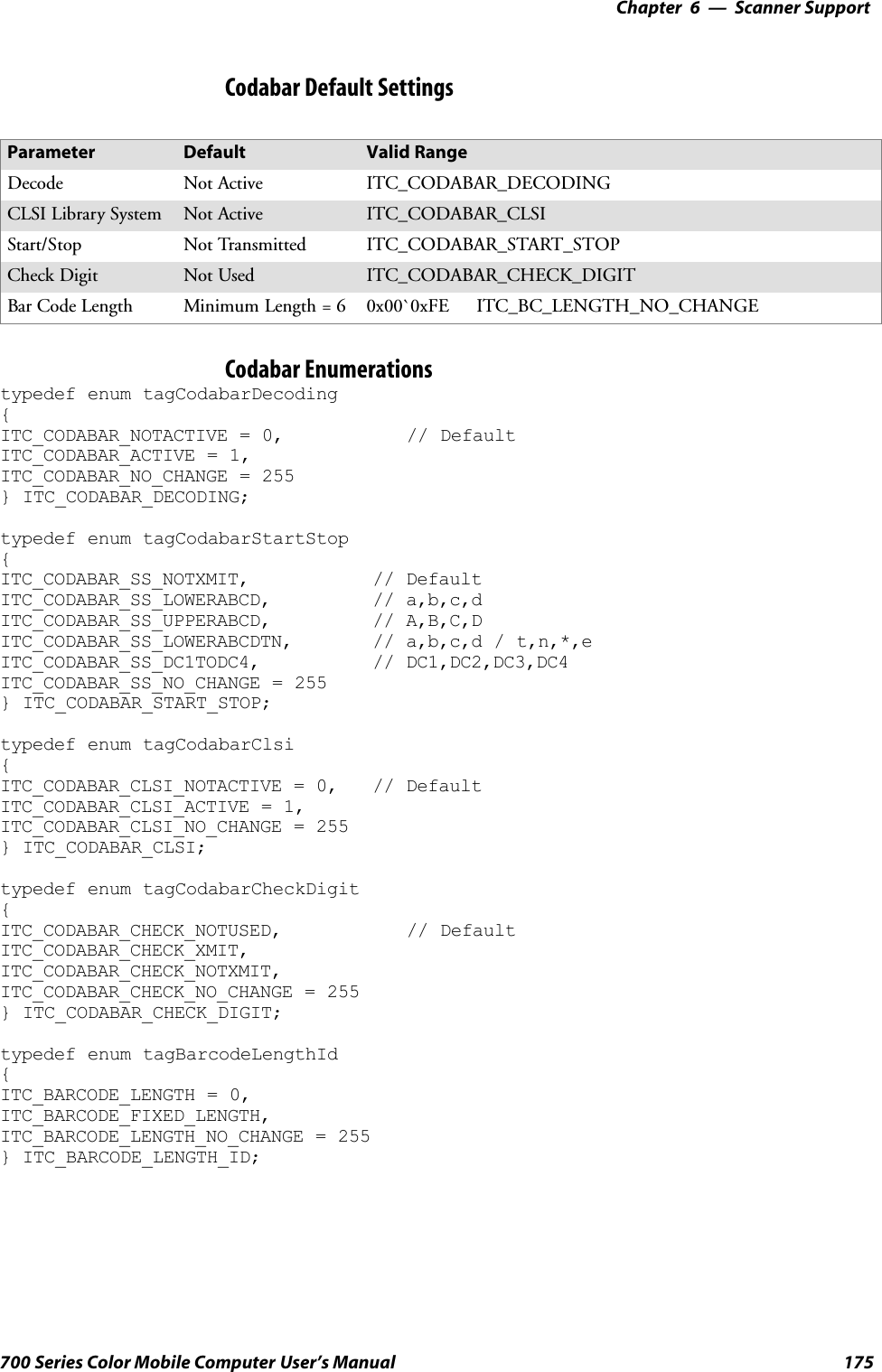
![6 Scanner Support—Chapter173700 Series Color Mobile Computer User’s ManualIS9CConfig::GetCodabarThis function retrieves the current settings of Codabar symbology.SyntaxHRESULT IS9CConfig::GetCodabar( ITC_CODABAR_DECODING*peDecode, ITC_CODABAR_START_STOP* peSS, ITC_CODABAR_CLSI*peCLSI, ITC_CODABAR_CHECK_DIGIT* peCheck,ITC_BARCODE_LENGTH_ID* peLengthId, BYTE rgbLengthBuff[],DWORD* pdwNumBytes );ParameterspeDecode [out] Pointer to the ITC_CODABAR_DECODINGlocation to receive the decoding for Codabarsymbology.peSS [out] Pointer to theITC_CODABAR_START_STOP location toreceive the Start/Stop option.peCLSI [out] Pointer to the ITC_CODABAR_CLSI locationto receive the CLSI library system.peCheck [out] Pointer to theITC_CODABAR_CHECK_DIGIT location toreceive the check digit.peLengthId [out] Pointer to the ITC_BARCODE_LENGTH_IDlocation to receive an indicator of eitherITC_BARCODE_LENGTH orITC_BARCODE_FIXED_LENGTH.rgbLengthBuff [out,size_is(3)]An array of bytes to receive 1 byte of data forITC_BARCODE_LENGTH, or 3 bytes of datafor ITC_BARCODE_FIXED_LENGTH.pdwNumBytes [out] Pointer to the DWORD location to receive anumber indicating number of bytes inrbgLengthBuff[]: 1 byte forITC_BARCODE_LENGTH or 3 bytes forITC_BARCODE_FIXED_LENGTH.Return ValuesHRESULT that indicates success or failure.RemarksNone.See AlsoNone.](https://usermanual.wiki/Intermec-Technologies/SB555.Item-5-from-FCC-email-Feb-07-2003/User-Guide-307179-Page-190.png)
![Scanner SupportChapter —6174 700 Series Color Mobile Computer User’s ManualIS9CConfig::SetCodabarThis function updates the Codabar settings with new values.SyntaxHRESULT IS9CConfig::SetCodabar( ITC_CODABAR_DECODINGeDecode, ITC_CODABAR_START_STOP eSS, ITC_CODABAR_CLSIeCLSI,ITC_CODABAR_CHECK_DIGIT eCheck, ITC_BARCODE_LENGTH_IDeLengthId, BYTE rgbLengthBuff[],DWORD dwNumBytes );ParameterseDecode [in] Identifies the decoding for Codabar symbology.eSS [in] Identifies the Start/Stop option.eCLSI [in] Identifies the CLSI library system.eCheck [in] Identifies the check digit.eLengthId [in] UseITC_BARCODE_LENGTH_NO_CHANGE toindicate no change for bar code length. UseITC_BARCODE_LENGTH for any length andminimum length, and set rgbLengthBuff[0] to avalid length value.Use ITC_BARCODE_FIXED_LENGTH tocompose 1 or 2 or 3 fixed lengths, and set 3 bytes:rgbLengthBuff[0],rgbLengthBuff[1],rgbLengthBuff[2] with valid values.rgbLengthBuff [in,size_is(dwNumBytes)]An array of bytes containing bar code lengths wheneLengthId = ITC_BARCODE_LENGTH orITC_BARCODE_FIXED_LENGTH.dwNumBytes [in] Number of bytes in rbgLengthBuff[]. For S9C, thisvalue is 1 wheneLengthId = ITC_BARCODE_LENGTH or 3when eLengthId =ITC_BARCODE_FIXED_LENGTHReturn ValuesHRESULT that indicates success or failure.RemarksNone.See AlsoNone.](https://usermanual.wiki/Intermec-Technologies/SB555.Item-5-from-FCC-email-Feb-07-2003/User-Guide-307179-Page-191.png)
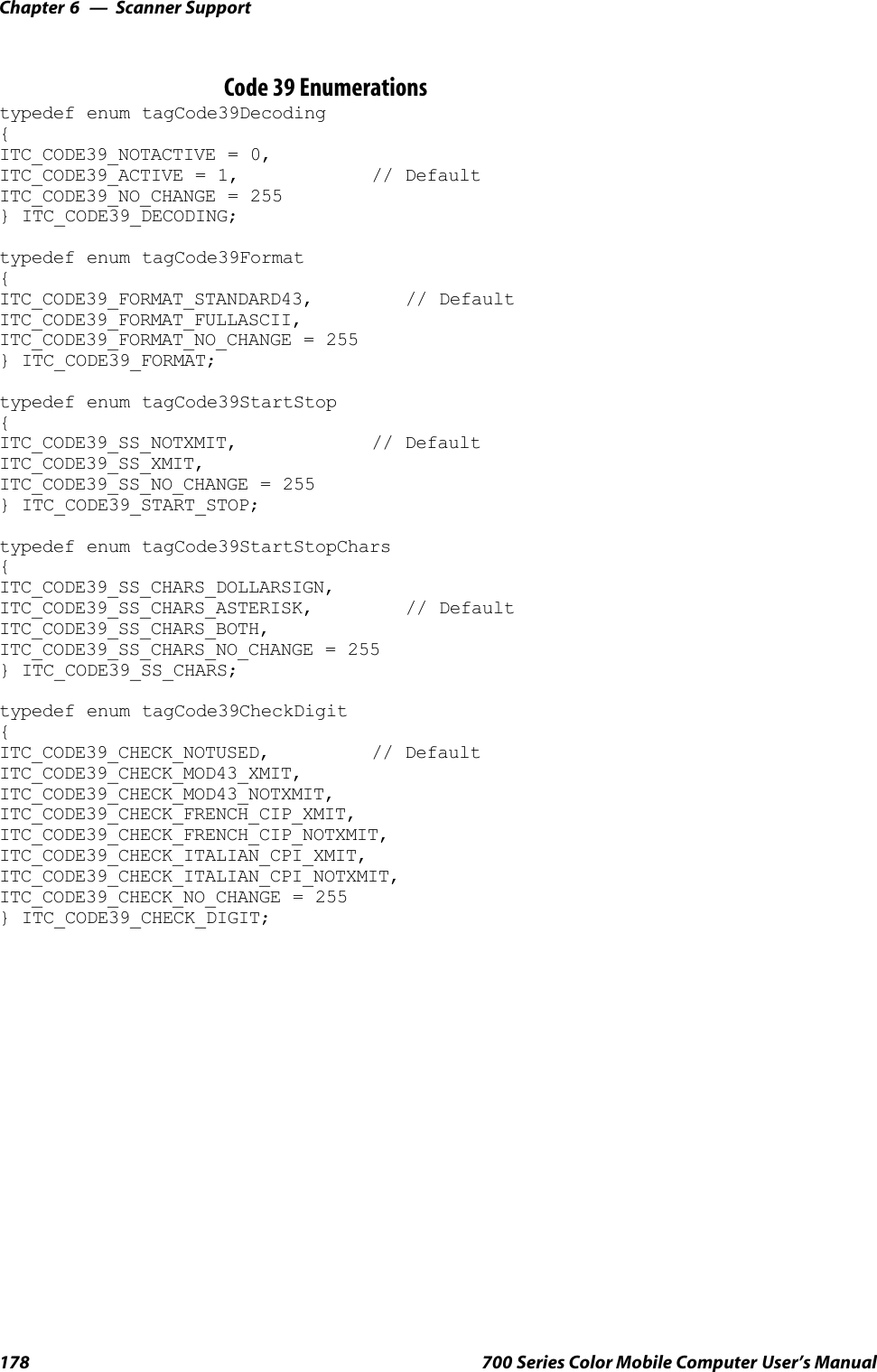
![Scanner SupportChapter —6176 700 Series Color Mobile Computer User’s ManualIS9CConfig::GetCode39This function retrieves the current settings of Code 39.SyntaxHRESULT IS9Cconfig::GetCode39( ITC_CODE39_DECODING*peDecode, ITC_CODE39_FORMAT* peFormat,ITC_CODE39_START_STOP* peSS,ITC_CODE39_SS_CHARS* peSSChars,ITC_CODE39_CHECK_DIGIT* peCheck, DWORD* pwLength );ParameterspeDecode [out] Pointer to the ITC_CODE39_DECODINGlocation to receive the decoding for Code 39.peFormat [out] Pointer to the ITC_CODE39_FORMAT locationto receive the Code 39 format.peSS [out] Pointer to the ITC_CODE39_START_STOPlocation to receive the Code 39 start/stop.peSSChars [out] Pointer to the ITC_CODE39_SS_CHARSlocation to receive the Start/Stop character.peCheck [out] Pointer to the ITC_CODE39_CHECK_DIGITlocation to receive the check digit.pwLength [out] Pointer to the DWORD location to receive the barcode length.Return ValuesHRESULT that indicates success or failure.RemarksNone.See AlsoNone.](https://usermanual.wiki/Intermec-Technologies/SB555.Item-5-from-FCC-email-Feb-07-2003/User-Guide-307179-Page-193.png)
![6 Scanner Support—Chapter177700 Series Color Mobile Computer User’s ManualIS9CConfig::SetCode39This function updates the Code 39 settings with new values.SyntaxHRESULT IS9CConfig::SetCode39( ITC_CODE39_DECODINGeDecode,ITC_CODE39_FORMAT eFormat, ITC_CODE39_START_STOPeSS,ITC_CODE39_SS_CHARS eSSChars, ITC_CODE39_CHECK_DIGITeCheck, DWORD dwLength );ParameterseDecode [in] Identifies the decoding for Code 39.eFormat [in] Identifies the Code 39 Format.eSS [in] Identifies the Start/Stop option.eSSChars [in] Identifies the Start/Stop character.eCheck [in] Identifies the Check digit.dwLength [in] Identifies the bar code length.Return ValuesHRESULT that indicates success or failure.RemarksNone.See AlsoNone.Code 39 Default SettingsParameter Default Valid RangeDecoding Active ITC_CODE39_DECODINGFormat Standard 43 Character ITC_CODE39_FORMATStart/Stop Not Transmitted ITC_CODE39_START_STOPAccepted Start/stop Characters *only ITC_CODE39_SS_CHARSCheck Digit Not Used ITC_CODE39_CHECK_DIGITBar Code Length Any Bar Code Length 0x00`0xFE ITC_BC_LENGTH_NO_CHANGE](https://usermanual.wiki/Intermec-Technologies/SB555.Item-5-from-FCC-email-Feb-07-2003/User-Guide-307179-Page-194.png)
![6 Scanner Support—Chapter179700 Series Color Mobile Computer User’s ManualIS9CConfig::GetCode93This function retrieves the current settings of Code 93.SyntaxHRESULT IS9CConfig::GetCode93( ITC_CODE93_DECODING*peDecode, DWORD* pdwLength );ParameterspeDecode [out] Pointer to the ITC_CODE93_DECODINGlocation to receive the decoding for Code 93symbology.pdwLength [out] Pointer to the DWORD location to receive a valuefor bar code length.Return ValuesHRESULT that indicates success or failure.RemarksNone.See AlsoNone.IS9CConfig::SetCode93This function updates the Code 93 settings with new values.SyntaxHRESULT IS9CConfig::SetCode93( ITC_CODE93_DECODINGeDecode,DWORD dwLength );ParameterseDecode [in] Identifies the decoding for Code93 Symbology.dwLength [in] Identifies the bar code length.Return ValuesHRESULT that indicates success or failure.RemarksNone.See AlsoNone.Code 93 Default SettingsParameter Default Valid RangeDecoding Not Active ITC_CODE93_DECODINGBar Code Length Any Bar Code Length 0x00`0xFE ITC_BC_LENGTH_NO_CHANGE](https://usermanual.wiki/Intermec-Technologies/SB555.Item-5-from-FCC-email-Feb-07-2003/User-Guide-307179-Page-196.png)
![Scanner SupportChapter —6180 700 Series Color Mobile Computer User’s ManualCode 93 EnumerationsUse this when the bar code length does not require any change.typedef enum tagCode93Decoding{ITC_CODE93_NOTACTIVE = 0, // DefaultITC_CODE93_ACTIVE = 1,ITC_CODE93_NO_CHANGE = 255} ITC_CODE93_DECODING;#define ITC_BC_LENGTH_NO_CHANGE 255.IS9CConfig::GetCode128This function retrieves the current settings of Code 128 symbology.SyntaxHRESULT IS9Cconfig::GetCode128( ITC_CODE128_DECODING*peDecode, ITC_EAN128_IDENTIFIER* peEan128Ident,ITC_CODE128_CIP128 peCip128State, BYTE* pbyFNC1, DWORD*pdwLength );ParameterspeDecode [out] Pointer to the ITC_CODE128_DECODINGlocation to receive the decoding for Code 128symbology.peEan128Ident [out] Pointer to the ITC_EAN128_IDENTIFIERlocation to receive the EAN 128 identifier.peCip128State [out] Pointer to the ITC_CODE128_CIP128location to receive the CIP 128.pbyFNC1 [out] Pointer to the BYTE location to receive theFNC1 separator character.pdwLength [out] Pointer to the DWORD location to receive avalue for bar code length.Return ValuesHRESULT that indicates success or failure.RemarksNone.See AlsoNone.](https://usermanual.wiki/Intermec-Technologies/SB555.Item-5-from-FCC-email-Feb-07-2003/User-Guide-307179-Page-197.png)
![6 Scanner Support—Chapter181700 Series Color Mobile Computer User’s ManualIS9CConfig::SetCode128This function updates the Code 128 settings with new values.SyntaxHRESULT IS9CConfig::SetCode128( ITC_CODE128_DECODINGeDecode, ITC_EAN128_IDENTIFIER eEan128Ident,ITC_CODE128_CIP128 eCip128State, BYTE byFNC1, DWORD dwLength);ParameterseDecode [in] Identifies the decoding for Code 128 symbology.eEan128Ident [in] Identifies the EAN 128 identifier.eCip128State [in] Identifies the CIP 128.byFNC1 [in] Identifies the FNC1 separator character, usuallyany ASCII value.dwLength [in] Identifies the bar code length.Return ValuesHRESULT that indicates success or failure.RemarksNone.See AlsoNone.Code 128/EAN 128 Default SettingsParameter Default Valid RangeDecoding Not Active ITC_CODE128_DECODINGEAN 128 Identifier Include ]C1 ITC_EAN128_IDENTIFIERCIP 128 French PharmaceuticalCodesNot Active ITC_CODE128_CIP128FNC1 Separator Character (EAN128 norms)GS function CharASCII 29 or 0x1D0x00`0xFE ITC_CODE128_FNC1_NO_CHANGEBar Code Length Any Bar Code Length 0x00`0xFE ITC_BC_LENGTH_NO_CHANGE](https://usermanual.wiki/Intermec-Technologies/SB555.Item-5-from-FCC-email-Feb-07-2003/User-Guide-307179-Page-198.png)
![Scanner SupportChapter —6182 700 Series Color Mobile Computer User’s ManualCode 128 Enumerationstypedef enum tagCode128Decoding{ITC_CODE128_NOTACTIVE = 0, // DefaultITC_CODE128_ACTIVE = 1,ITC_CODE128_NO_CHANGE = 255} ITC_CODE128_DECODING;typedef enum tagEan128Identifier{ITC_EAN128_ID_REMOVE,ITC_EAN128_ID_INCLUDE, // DefaultITC_EAN128_ID_NO_CHANGE = 255} ITC_EAN128_IDENTIFIER;typedef enum tagCode128Cip128{ITC_CODE128_CIP128_NOTACTIVE = 0, // DefaultITC_CODE128_CIP128_ACTIVE = 1,ITC_CODE128_CIP128_NO_CHANGE = 255} ITC_CODE128_CIP128;#define ITC_CODE128_FNC1_NO_CHANGE 255.This definition can be used when the Code128 FNC1 does not require any change.#define ITC_BC_LENGTH_NO_CHANGE 255. This definition can be used when the barcode length does not require any change.The table below shows what to be expected for EAN 128 labels for varioussymbology identifier transmit configurations and EAN 128 Identifier op-tions.Setup Application’s Expected ResultEAN 128 ]C1 ID Symbology ID option EAN 128 Label Other Labels1 Include ]C1 Disabled <data> <data>2Remove]C1Disabled <data> <data>3 Include ]C1 AIM ID Transmitted ]C1<data> ]XY<data>4Remove]C1AIDIDTransmitted ]C1<data> ]XY<data>5 Include ]C1 Custom ID Transmitted Z]C1<data> Z<data>6Remove]C1Custom ID Transmitted Z<data> Z<data>where “X” is the symbology identifier, “Y” is the modifier character, and “Z” is the 1-byte symbology identifier.](https://usermanual.wiki/Intermec-Technologies/SB555.Item-5-from-FCC-email-Feb-07-2003/User-Guide-307179-Page-199.png)
![6 Scanner Support—Chapter183700 Series Color Mobile Computer User’s ManualIS9CConfig::GetI2of5This function retrieves the current settings of Interleaved 2 of 5.SyntaxHRESULT IS9CConfig::GetI2of5( ITC_INTERLEAVED2OF5_DECODING*peDecode, ITC_INTERLEAVED2OF5_CHECK_DIGIT* peCheck,ITC_BARCODE_LENGTH_ID* peLengthId, BYTE rbgLengthBuff[],DWORD* pdwNumBytes );ParameterspeDecode [out] Pointer to theITC_INTERLEAVED2OF5_DECODINGlocation to receive the decoding for Interleaved2 of 5 symbology.peCheck [out] Pointer to theITC_INTERLEAVED2OF5_CHECK_DIGITlocation to receive the check digit.peLengthId [out] Pointer to the ITC_BARCODE_LENGTH_IDlocation to receive an indicator of eitherITC_BARCODE_LENGTH orITC_BARCODE_FIXED_LENGTH.rgbLengthBuff [out,size_is(3)]An array of bytes to receives 1 byte of data forITC_BARCODE_LENGTH or 3 bytes of datafor ITC_BARCODE_FIXED_LENGTH.pdwNumBytes [out] Pointer to the DWORD location to receive anumber indicating number of bytes inrbgLengthBuff[]: 1 byte forITC_BARCODE_LENGTH or 3 bytes forITC_BARCODE_FIXED_LENGTH.Return ValuesHRESULT that indicates success or failure.RemarksNone.See AlsoNone.](https://usermanual.wiki/Intermec-Technologies/SB555.Item-5-from-FCC-email-Feb-07-2003/User-Guide-307179-Page-200.png)
![Scanner SupportChapter —6184 700 Series Color Mobile Computer User’s ManualIS9CConfig::SetI2of5This function updates the Interleaved 2 of 5 settings with new values.SyntaxHRESULT IS9CConfig::SetI2of5( ITC_INTERLEAVED2OF5_DECODINGeDecode, ITC_INTERLEAVED2OF5_CHECK_DIGIT eCheck,ITC_BARCODE_LENGTH_ID eLengthId, BYTE rgbLengthBuff[], DWORDdwNumBytes );ParameterseDecode [in] Identifies the decoding for Interleaved 2 of 5symbology.eCheck [in] Identifies the check digit.eLengthId [in] UseITC_BARCODE_LENGTH_NO_CHANGE toindicate no change for bar code length. UseITC_BARCODE_LENGTH for any length andminimum length, and set rgbLengthBuff[0] to avalid length value. UseITC_BARCODE_FIXED_LENGTH to compose1 or 2 or 3 fixed lengths, and set 3 bytes:rgbLengthBuff[0],rgbLengthBuff[1],rgbLengthBuff[2] with valid values.rgbLengthBuff [in,size_is(dwNumBytes)]Contains bar code lengths when eLengthId =Use ITC_BARCODE_LENGTH orUse ITC_BARCODE_FIXED_LENGTH.dwNumBytes [in] Number of bytes in rbgLengthBuff[]. For S9C, thisvalue is 1 when eLengthId =ITC_BARCODE_LENGTH or 3 when eLengthId= ITC_BARCODE_FIXED_LENGTH.Return ValuesHRESULT that indicates success or failure.RemarksNone.See AlsoNone.Interleaved 2 of 5 Default SettingsParameter Default Valid RangeDecoding Not Active ITC_INTERLEAVED2OF5_DECODINGCheck Digit Not Used ITC_INTERLEAVED2OF5_CHECK_DIGITBar Code Length Minimum Length = 6 0x00`0xFE ITC_BC_LENGTH_NO_CHANGE](https://usermanual.wiki/Intermec-Technologies/SB555.Item-5-from-FCC-email-Feb-07-2003/User-Guide-307179-Page-201.png)
![6 Scanner Support—Chapter185700 Series Color Mobile Computer User’s ManualInterleaved 2 of 5 Enumerationstypedef enum tagInterleaved2of5Decoding{ITC_INTERLEAVED2OF5_NOTACTIVE = 0, // DefaultITC_INTERLEAVED2OF5_ACTIVE = 1,ITC_INTERLEAVED2OF5_NO_CHANGE = 255} ITC_INTERLEAVED2OF5_DECODING;typedef enum tagInterleaved2of5CheckDigit{ITC_INTERLEAVED2OF5_CHECK_NOTUSED, // DefaultITC_INTERLEAVED2OF5_CHECK_MOD10_XMIT,ITC_INTERLEAVED2OF5_CHECK_MOD10_NOTXMIT,ITC_INTERLEAVED2OF5_CHECK_FRENCH_CIP_XMIT,ITC_INTERLEAVED2OF5_CHECK_FRENCH_CIP_NOTXMIT,ITC_INTERLEAVED2OF5_CHECK_NO_CHANGE = 255} ITC_INTERLEAVED2OF5_CHECK_DIGIT;typedef enum tagBarcodeLengthId{ITC_BARCODE_LENGTH = 0,ITC_BARCODE_FIXED_LENGTH,ITC_BARCODE_LENGTH_NO_CHANGE = 255} ITC_BARCODE_LENGTH_ID;IS9CConfig::GetMatrix2of5This function retrieves the current settings of Matrix 2 of 5.SyntaxHRESULT IS9CConfig::GetMatrix2of5( ITC_MATRIX2OF5_DECODING*peDecode, DWORD* pdwLength );ParameterspeDecode [out] Pointer to the ITC_MATRIX2OF5_DECODINGlocation to receive the decoding for Matrix 2 of 5symbology.pdwLength [out] Pointer to the DWORD location to receive a valuefor the bar code length.Return ValuesHRESULT that indicates success or failure.RemarksNone.See AlsoNone.](https://usermanual.wiki/Intermec-Technologies/SB555.Item-5-from-FCC-email-Feb-07-2003/User-Guide-307179-Page-202.png)
![Scanner SupportChapter —6186 700 Series Color Mobile Computer User’s ManualIS9CConfig::SetMatrix2of5This function updates the Matrix 2 of 5 settings with new values.SyntaxHRESULT IS9CConfig::SetMatrix2of5( ITC_MATRIX2OF5_DECODINGeDecode, DWORD dwLength );ParameterseDecode [in] Identifies the decoding for Matrix 2 of 5 symbology.dwLength [in] Identifies the bar code length.Return ValuesHRESULT that indicates success or failure.RemarksNone.See AlsoNone.Matrix 2 of 5 Default SettingsParameter Default Valid RangeDecoding Not Active ITC_MATRIX2OF5_DECODINGBar Code Length Minimum Length = 6 0x00`0xFE ITC_BC_LENGTH_NO_CHANGEMatrix 2 of 5 Enumerationstypedef enum tagMatrix2of5Decoding{ITC_MATRIX2OF5_NOTACTIVE = 0, // DefaultITC_MATRIX2OF5_ACTIVE = 1,ITC_MATRIX2OF5_NO_CHANGE = 255} ITC_MATRIX2OF5_DECODING;#define ITC_BC_LENGTH_NO_CHANGE 255. This definition can be used when the barcode length does not require any change.](https://usermanual.wiki/Intermec-Technologies/SB555.Item-5-from-FCC-email-Feb-07-2003/User-Guide-307179-Page-203.png)
![6 Scanner Support—Chapter187700 Series Color Mobile Computer User’s ManualIS9CConfig::GetMSIThis function retrieves the current MSI settings.SyntaxHRESULT IS9CConfig::GetMSI( ITC_MSI_DECODING* peDecode,ITC_MSI_CHECK_DIGIT* peCheck, DWORD* pdwLength );ParameterspeDecode [out] Pointer to the ITC_MSI_DECODING location toreceive the decoding for MSI symbology.peCheck [out] Pointer to the ITC_MSI_CHECK_DIGITlocation to receive the check digit.pdwLength [out] Pointer to the DWORD location to receive the barcode length.Return ValuesHRESULT that indicates success or failure.RemarksNone.See AlsoNone.IS9CConfig::SetMSIThis function updates the MSI settings with new values.SyntaxHRESULT IS9CConfig::SetMSI( ITC_MSI_DECODING eDecode,ITC_MSI_CHECK_DIGIT eCheck, DWORD dwLength );ParameterseDecode [in] Identifies the decoding for MSI symbology.eCheck [in] Identifies the check digit.dwLength [in] Identifies the bar code length.Return ValuesHRESULT that indicates success or failure.RemarksNone.See AlsoNone.MSI Default SettingsParameter Default Valid RangeDecoding Not Active ITC_MSI_DECODINGCheck Digit MOD 10 checked and transmitted ITC_MSI_CHECK_DIGITBar Code Length Minimum Length = 6 0x00`0xFE ITC_BC_LENGTH_NO_CHANGE](https://usermanual.wiki/Intermec-Technologies/SB555.Item-5-from-FCC-email-Feb-07-2003/User-Guide-307179-Page-204.png)
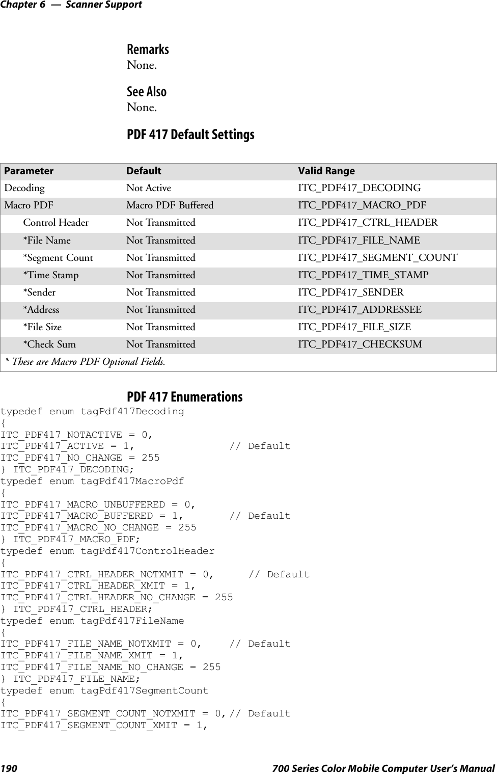
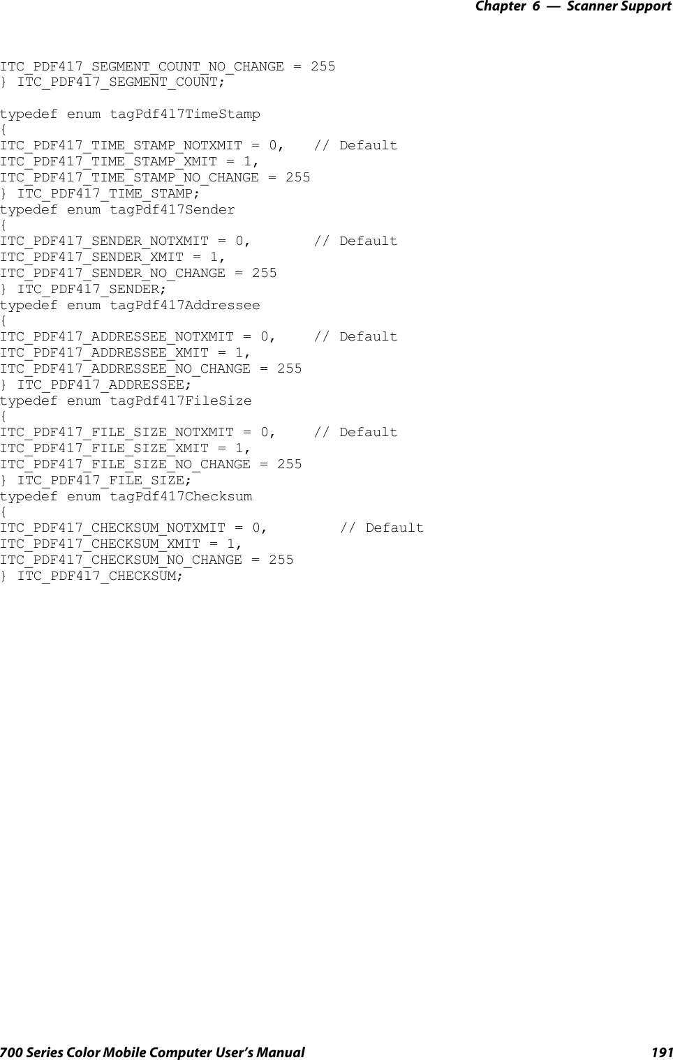
![Scanner SupportChapter —6188 700 Series Color Mobile Computer User’s ManualMSI Enumerationstypedef enum tagMsiDecoding{ITC_MSI_NOTACTIVE = 0, // DefaultITC_MSI_ACTIVE = 1,ITC_MSI_NO_CHANGE = 255} ITC_MSI_DECODING;typedef enum tagMsiCheckDigit{ITC_MSI_CHECK_MOD10_XMIT, // DefaultITC_MSI_CHECK_MOD10_NOTXMIT,ITC_MSI_CHECK_DOUBLEMOD10_XMIT,ITC_MSI_CHECK_DOUBLEMOD10_NOTXMIT,ITC_MSI_CHECK_NO_CHANGE = 255} ITC_MSI_CHECK_DIGIT;#define ITC_BC_LENGTH_NO_CHANGE 255. This definition can be used when the barcode length does not require any change.IS9CConfig::GetPDF417This function retrieves the current PDF417 settings.SyntaxHRESULT IS9CConfig::GetPDF417( ITC_PDF417_DECODING*pePdf417Decode, ITC_PDF417_MACRO_PDF* peMacroPdf,ITC_PDF417_CTRL_HEADER* pePdfControlHeader,ITC_PDF417_FILE_NAME* pePdfFileName,ITC_PDF417_SEGMENT_COUNT* pePdfSegmentCount,ITC_PDF417_TIME_STAMP* pePdfTimeStamp, ITC_PDF417_SENDER*pePdfSender, ITC_PDF417_ADDRESSEE* pePdfAddressee,ITC_PDF417_FILE_SIZE* pePdfFileSize, ITC_PDF417_CHECKSUM*pePdfChecksum );ParameterspePdf417Decode [out] Pointer to theITC_PDF417_DECODING location toreceive the decoding for PDF417symbology.peMacroPdf [out] Pointer to theITC_PDF417_MACRO_PDF location toreceive the Macro PDF.pePdfControlHeader [out] Pointer to theITC_PDF417_CTRL_HEADER locationto receive the control header.pePdfFileName [out] Pointer to theITC_PDF417_FILE_NAME location toreceive the file name.pePdfSegmentCount [out] Pointer to theITC_PDF417_SEGMENT_COUNTlocation to receive the segment count.pePdfTimeStamp [out] Pointer to theITC_PDF417_TIME_STAMP location toreceive the time stamp.](https://usermanual.wiki/Intermec-Technologies/SB555.Item-5-from-FCC-email-Feb-07-2003/User-Guide-307179-Page-205.png)
![6 Scanner Support—Chapter189700 Series Color Mobile Computer User’s ManualpePdfSender [out] Pointer to the ITC_PDF417_SENDERlocation to receive the sender.pePdfAddressee [out] Pointer to theITC_PDF417_ADDRESSEE location toreceive the addressee.pePdfFileSize [out] Pointer to the ITC_PDF417_FILE_SIZElocation to receive the file size.pePdfChecksum [out] Pointer to theITC_PDF417_CHECKSUM location toreceive the checksum.Return ValuesHRESULT that indicates success or failure.RemarksNone.See AlsoNone.IS9CConfig::SetPDF417This function updates the PDF417 settings with new values.SyntaxHRESULT IS9CConfig::SetPDF417( ITC_PDF417_DECODINGePdf417Decode, ITC_PDF417_MACRO_PDF eMacroPdf,ITC_PDF417_CTRL_HEADER ePdfControlHeader,ITC_PDF417_FILE_NAME ePdfFileName, ITC_PDF417_SEGMENT_COUNTePdfSegmentCount, ITC_PDF417_TIME_STAMP ePdfTimeStamp,ITC_PDF417_SENDER ePdfSender, ITC_PDF417_ADDRESSEEePdfAddressee, ITC_PDF417_FILE_SIZE ePdfFileSize,ITC_PDF417_CHECKSUM ePdfChecksum );ParametersePdf417Decode [in] Identifies the decoding for PDF417 symbology.eMacroPdf [in] Identifies the Macro PDF.ePdfControlHeader [in] Identifies the control header.ePdfFileName [in] Identifies the file name.ePdfSegmentCount [in] Identifies the segment count.ePdfTimeStamp [in] Identifies the time stamp.ePdfSender [in] Identifies the sender.ePdfAddressee [in] Identifies the addressee.ePdfFileSize [in] Identifies the file size.ePdfChecksum [in] Identifies the checksum.Return ValuesHRESULT that indicates success or failure.](https://usermanual.wiki/Intermec-Technologies/SB555.Item-5-from-FCC-email-Feb-07-2003/User-Guide-307179-Page-206.png)
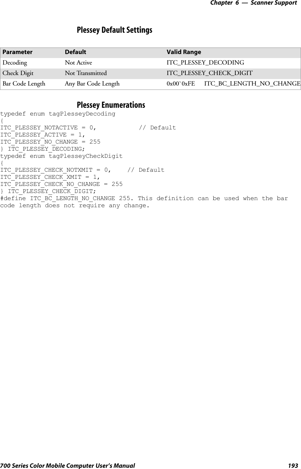
![Scanner SupportChapter —6192 700 Series Color Mobile Computer User’s ManualIS9CConfig::GetPlesseyThis function retrieves the current Plessey settings.SyntaxHRESULT IS9CConfig::GetPlessey( ITC_PLESSEY_DECODING*peDecode, ITC_PLESSEY_CHECK_DIGIT* peCheck, DWORD* pdwLength);ParameterspeDecode [out] Pointer to the ITC_PLESSEY_DECODINGlocation to receive the decoding for Plesseysymbology.peCheck [out] Pointer to the ITC_PLESSEY_CHECK_DIGITlocation to receive the check digit.pdwLength [out] Pointer to the DWORD location to receive the barcode length.Return ValuesHRESULT that indicates success or failure.RemarksNone.See AlsoNone.IS9CConfig::SetPlesseyThis function updates the Plessey settings with new values.SyntaxHRESULT IS9CConfig::SetPlessey( ITC_PLESSEY_DECODINGeDecode, ITC_PLESSEY_CHECK_DIGIT eCheck, DWORD dwLength );ParameterseDecode [in] Identifies the decoding for Plessey symbology.eCheck [in] Identifies the check digit.dwLength [in] Identifies the bar code length.Return ValuesHRESULT that indicates success or failure.RemarksNone.See AlsoNone.](https://usermanual.wiki/Intermec-Technologies/SB555.Item-5-from-FCC-email-Feb-07-2003/User-Guide-307179-Page-209.png)
![Scanner SupportChapter —6194 700 Series Color Mobile Computer User’s ManualIS9CConfig::GetStandard2of5This function retrieves the current Standard 2 of 5 settings.SyntaxHRESULT IS9CConfig::GetStandard2of5(ITC_STANDARD2OF5_DECODING* peDecode,ITC_STANDARD2OF5_FORMAT* peFormat,ITC_STANDARD2OF5_CHECK_DIGIT* peCheck,ITC_BARCODE_LENGTH_ID* peLengthId, BYTE rgbLengthBuff,DWORD* pdwNumBytes );ParameterspeDecode [out] Pointer to theITC_STANDARD2OF5_DECODINGlocation to receive the decoding for Standard2 of 5 symbology.peFormat [out] Pointer to theITC_STANDARD2OF5_FORMAT locationto receive the format.peCheck [out] Pointer to theITC_STANDARD2OF5_CHECK_DIGITlocation to receive Modulo 10 check digit.peLengthId [out] Pointer to the ITC_BARCODE_LENGTH_IDlocation to receive an indicator of eitherITC_BARCODE_LENGTH orITC_BARCODE_FIXED_LENGTH.rgbLengthBuff [out,size_is(3)]An array of bytes to receives 1 byte of data forITC_BARCODE_LENGTH, or 3 bytes of datafor ITC_BARCODE_FIXED_LENGTH.pdwNumBytes [out] Pointer to the DWORD location to receive anumber indicating number of bytes inrbgLengthBuff[]: 1 byte forITC_BARCODE_LENGTH or 3 bytes forITC_BARCODE_FIXED_LENGTH.Return ValuesHRESULT that indicates success or failure.RemarksNone.See AlsoNone.](https://usermanual.wiki/Intermec-Technologies/SB555.Item-5-from-FCC-email-Feb-07-2003/User-Guide-307179-Page-211.png)
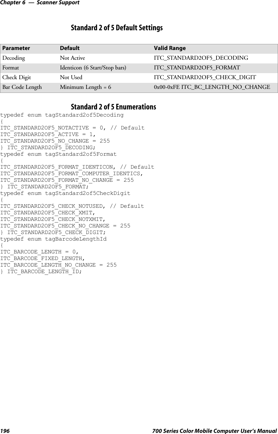
![6 Scanner Support—Chapter195700 Series Color Mobile Computer User’s ManualIS9CConfig::SetStandard2of5This function updates the Standard 2 of 5 settings with new values.SyntaxHRESULT IS9CConfig::SetStandard2of5(ITC_STANDARD2OF5_DECODING eDecode, ITC_STANDARD2OF5_FORMATeFormat, ITC_STANDARD2OF5_CHECK_DIGIT eCheck,ITC_BARCODE_LENGTH_ID eLengthId, BYTE rgbLengthBuff[], DWORDdwNumBytes );ParameterseDecode [in] Identifies the decoding for Standard 2 of 5symbology.eFormat [in] Identifies the format.eCheck [in] Identifies the Modulo 10 check digit.eLengthId [in] UseITC_BARCODE_LENGTH_NO_CHANGE toindicate no change for bar code length. UseITC_BARCODE_LENGTH for any length andminimum length, and set rgbLengthBuff[0] to avalid length value. UseITC_BARCODE_FIXED_LENGTH to compose1 or 2 or 3 fixed lengths, and set 3 bytes:rgbLengthBuff[0],rgbLengthBuff[1],rgbLengthBuff[2] with valid values.rgbLengthBuff [in,size_is(dwNumBytes)]An array of bytes containing bar code lengths wheneLengthId = ITC_BARCODE_LENGTH orITC_BARCODE_FIXED_LENGTH.dwNumBytes [in] Number of bytes in rbgLengthBuff[]. For S9C, thisvalue is 1 when eLengthId =ITC_BARCODE_LENGTH or 3 when eLengthId= ITC_BARCODE_FIXED_LENGTH.Return ValuesHRESULT that indicates success or failure.RemarksNone.See AlsoNone.](https://usermanual.wiki/Intermec-Technologies/SB555.Item-5-from-FCC-email-Feb-07-2003/User-Guide-307179-Page-212.png)
![6 Scanner Support—Chapter197700 Series Color Mobile Computer User’s ManualIS9CConfig::GetTelepenThis function retrieves the current Telepen settings.SyntaxHRESULT IS9CConfig::GetTelepen( ITC_TELEPEN_DECODING*peDecode, ITC_TELEPEN_FORMAT* peFormat );ParameterspeDecode [out] Pointer to the ITC_TELEPEN_DECODINGlocation to receive the decoding for TELEPENsymbology.peFormat [out] Pointer to the ITC_TELEPEN_FORMAT location toreceive the format.Return ValuesHRESULT that indicates success or failure.RemarksNone.See AlsoNone.IS9CConfig::SetTelepenThis function updates the Telepen settings with new values.SyntaxHRESULT IS9CConfig::SetTelepen( ITC_TELEPEN_DECODING*eDecode, ITC_TELEPEN_FORMAT* eFormat );ParameterseDecode [in] Identifies the decoding for Telepen symbology.eFormat [in] Identifies the format.Return ValuesHRESULT that indicates success or failure.RemarksNone.See AlsoNone.Telepen Default SettingsParameter Default Valid RangeDecoding Not Active ITC_TELEPEN_DECODINGFormat ASCII ITC_TELEPEN_FORMAT](https://usermanual.wiki/Intermec-Technologies/SB555.Item-5-from-FCC-email-Feb-07-2003/User-Guide-307179-Page-214.png)
![Scanner SupportChapter —6198 700 Series Color Mobile Computer User’s ManualTelepen Enumerationstypedef enum tagTelepenDecoding{ITC_TELEPEN_NOTACTIVE = 0, // DefaultITC_TELEPEN_ACTIVE = 1,ITC_TELEPEN_NO_CHANGE = 255} ITC_TELEPEN_DECODING;typedef enum tagTelepenDecoding{ITC_TELEPEN_FORMAT_ASCII, // DefaultITC_TELEPEN_FORMAT_NUMERIC,ITC_TELEPEN_FORMAT_NO_CHANGE = 255} ITC_TELEPEN_FORMAT;IS9CConfig::GetUpcEanThis function retrieves the current UPC/EAN settings.SyntaxHRESULT IS9CConfig::GetUpcEan( ITC_UPCEAN_DECODING*upceanDecode, ITC_UPCA_SELECT* upcASelect, ITC_UPCE_SELECT*upcESelect, ITC_EAN8_SELECT* ean8Select, ITC_EAN13_SELECT*ean13Select, ITC_UPCEAN_ADDON_DIGITS* upcAddOnDigits,ITC_UPCEAN_ADDON_TWO* upcAddOn2, ITC_UPCEAN_ADDON_FIVE*upcAddOn5, ITC_UPCA_CHECK_DIGIT* upcACheck,ITC_UPCE_CHECK_DIGIT* upcECheck, ITC_EAN8_CHECK_DIGIT*ean8Check, ITC_EAN13_CHECK_DIGIT* ean13Check,ITC_UPCA_NUMBER_SYSTEM* upcANumSystem,ITC_UPCE_NUMBER_SYSTEM* upcENumSystem, ITC_UPCA_REENCODE*upcAReencode, ITC_UPCE_REENCODE* upcEReencode,ITC_EAN8_REENCODE* ean8Reencode );ParametersupceanDecode [out] Pointer to the ITC_UPCEAN_DECODINGlocation to receive the decoding for UPC/EANsymbology.upcASelect [out] Pointer to the ITC_UPCA_SELECT location toreceive the UPC-A selection state.upcESelect [out] Pointer to the ITC_UPCE_SELECT location toreceive the UPC-E selection state.ean8Select [out] Pointer to the ITC_EAN8_SELECT location toreceive the EAN-8 selection state.ean13Select [out] Pointer to the ITC_EAN13_SELECT locationto receive the EAN-13 selection state.upcAddOnDigits [out] Pointer to theITC_UPCEAN_ADDON_DIGITS location toreceive the add-on digits.upcAddOn2 [out] Pointer to theITC_UPCEAN_ADDON_TWO location toreceive the add-on 2 digits.upcAddOn5 [out] Pointer to the ITC_UPCEAN_ADDON_FIVElocation to receive the add-on 5 digits.](https://usermanual.wiki/Intermec-Technologies/SB555.Item-5-from-FCC-email-Feb-07-2003/User-Guide-307179-Page-215.png)
![6 Scanner Support—Chapter199700 Series Color Mobile Computer User’s ManualupcACheck [out] Pointer to the ITC_UPCA_CHECK_DIGITlocation to receive the UPC-A check digit.upcECheck [out] Pointer to the ITC_UPCE_CHECK_DIGITlocation to receive the UPC-E check digit.ean8Check [out] Pointer to the ITC_EAN8_CHECK_DIGITlocation to receive the EAN-8 check digit.ean13Check [out] Pointer to the ITC_EAN13_CHECK_DIGITlocation to receive the EAN-13 check digit.upcANumSystem [out] Pointer to theITC_UPCA_NUMBER_SYSTEM location toreceive the UPC-A number system.upcENumSystem [out] Pointer to theITC_UPCE_NUMBER_SYSTEM location toreceive the UPC-E number system.upcAReencode [out] Pointer to the ITC_UPCA_REENCODElocation to receive the UPC-A reencoding.upcEReencode [out] Pointer to the ITC_UPCE_REENCODElocation to receive the UPC-E reencoding.ean8Reencode [out] Pointer to the ITC_EAN8_REENCODElocation to receive the EAN-8 reencoding.Return ValuesHRESULT that indicates success or failure.RemarksNone.See AlsoNone.](https://usermanual.wiki/Intermec-Technologies/SB555.Item-5-from-FCC-email-Feb-07-2003/User-Guide-307179-Page-216.png)
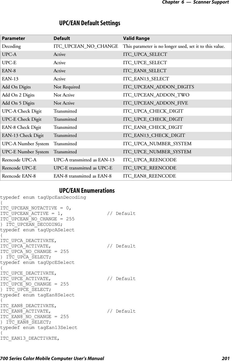
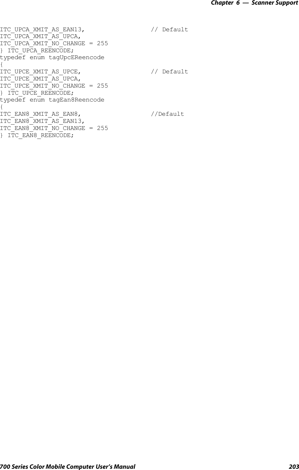
![Scanner SupportChapter —6200 700 Series Color Mobile Computer User’s ManualIS9CConfig::SetUpcEanThis function updates the UPC/EAN settings with new values.SyntaxHRESULT IS9CConfig::SetUpcEan( ITC_UPCEAN_DECODINGupceanDecode, ITC_UPCA_SELECT upcASelect, ITC_UPCE_SELECTupcESelect, ITC_EAN8_SELECT ean8Select, ITC_EAN13_SELECTean13Select, ITC_UPCEAN_ADDON_DIGITS upcAddOnDigits,ITC_UPCEAN_ADDON_TWO upcAddOn2, ITC_UPCEAN_ADDON_FIVEupcAddOn5, ITC_UPCA_CHECK_DIGIT upcACheck,ITC_UPCE_CHECK_DIGIT upcECheck, ITC_EAN8_CHECK_DIGITean8Check, ITC_EAN13_CHECK_DIGIT ean13Check,ITC_UPCA_NUMBER_SYSTEM upcANumSystem, ITC_UPCE_NUMBER_SYSTEMupcENumSystem, ITC_UPCA_REENCODE upcAReencode,ITC_UPCE_REENCODE upcEReencode, ITC_EAN8_REENCODEean8Reencode );ParametersupceanDecode [in] Identifies the decoding for UPC/EAN symbology.upcASelect [in] Identifies the UPC-A selection state.upcESelect [in] Identifies the UPC-E selection state.ean8Select [in] Identifies the EAN-8 selection state.ean13Select [in] Identifies the EAN-13 selection state.upcAddOnDigits [in] Identifies the Add-on digits.upcAddOn2 [in] Identifies the Add-on 2 digits.upcAddOn5 [in] Identifies the Add-on 5 digits.upcACheck [in] Identifies the UPC-A check digit.upcECheck [in] Identifies the UPC-E check digit.ean8Check [in] Identifies the EAN-8 check digit.ean13Check [in] Identifies the EAN-13 check digit.upcANumSystem [in] Identifies the UPC-A number system.upcENumSystem [in] Identifies the UPC-E number system.upcAReencode [in] Identifies the UPC-A reencoding.upcEReencode [in] Identifies the UPC-E reencoding.ean8Reencode [in] Identifies the EAN-8 reencoding.Return ValuesHRESULT that indicates success or failure.RemarksNone.See AlsoNone.](https://usermanual.wiki/Intermec-Technologies/SB555.Item-5-from-FCC-email-Feb-07-2003/User-Guide-307179-Page-217.png)
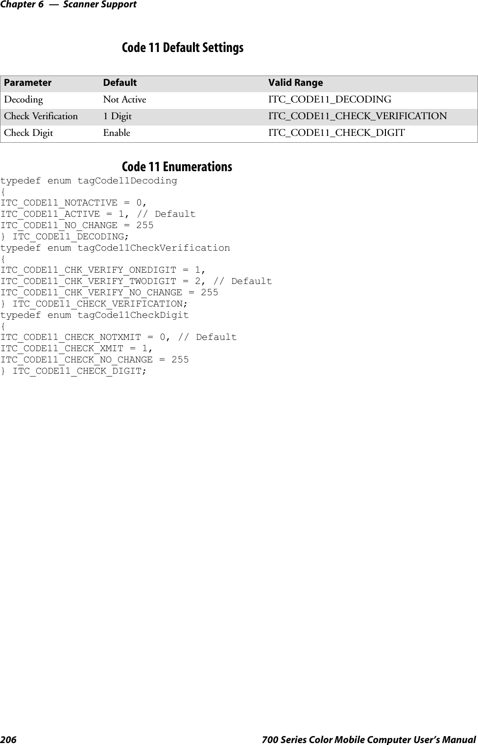
![6 Scanner Support—Chapter205700 Series Color Mobile Computer User’s ManualIS9CConfig2::GetCode11This function retrieves the current settings for Code 11.SyntaxHRESULT GetCode11( ITC_CODE11_DECODING* peDecode,ITC_CODE11_CHECK_DIGIT* peCheck,ITC_CODE11_CHECK_VERIFICATION* peVer );ParameterspeDecode [out] Pointer to ITC_CODE11_DECODING location toreceive Code 11 decoding.peCheck [out] Pointer to ITC_CODE11_CHECK_DIGIT locationto receive the check digit option.peVer [out] Pointer toITC_CODE11_CHECK_VERIFICATION locationto receive the check verification option.Return ValuesHRESULT that indicates success or failure.RemarksNone.See AlsoNone.IS9CConfig2::SetCode11This function updates the current setting of Code 11 symbology.SyntaxHRESULT SetCode11( ITC_CODE11_DECODING eDecode,ITC_CODE11_CHECK_DIGIT eCheck, ITC_CODE11_CHECK_VERIFICATIONeVer );ParameterseDecode [in] An enumeration that identifies decoding option forCode 11.eCheck [in] An enumeration that identifies the check digit option.eVer [in] An enumeration that identifies check verification option.Return ValuesHRESULT that indicates success or failure.RemarksNone.See AlsoNone.](https://usermanual.wiki/Intermec-Technologies/SB555.Item-5-from-FCC-email-Feb-07-2003/User-Guide-307179-Page-222.png)
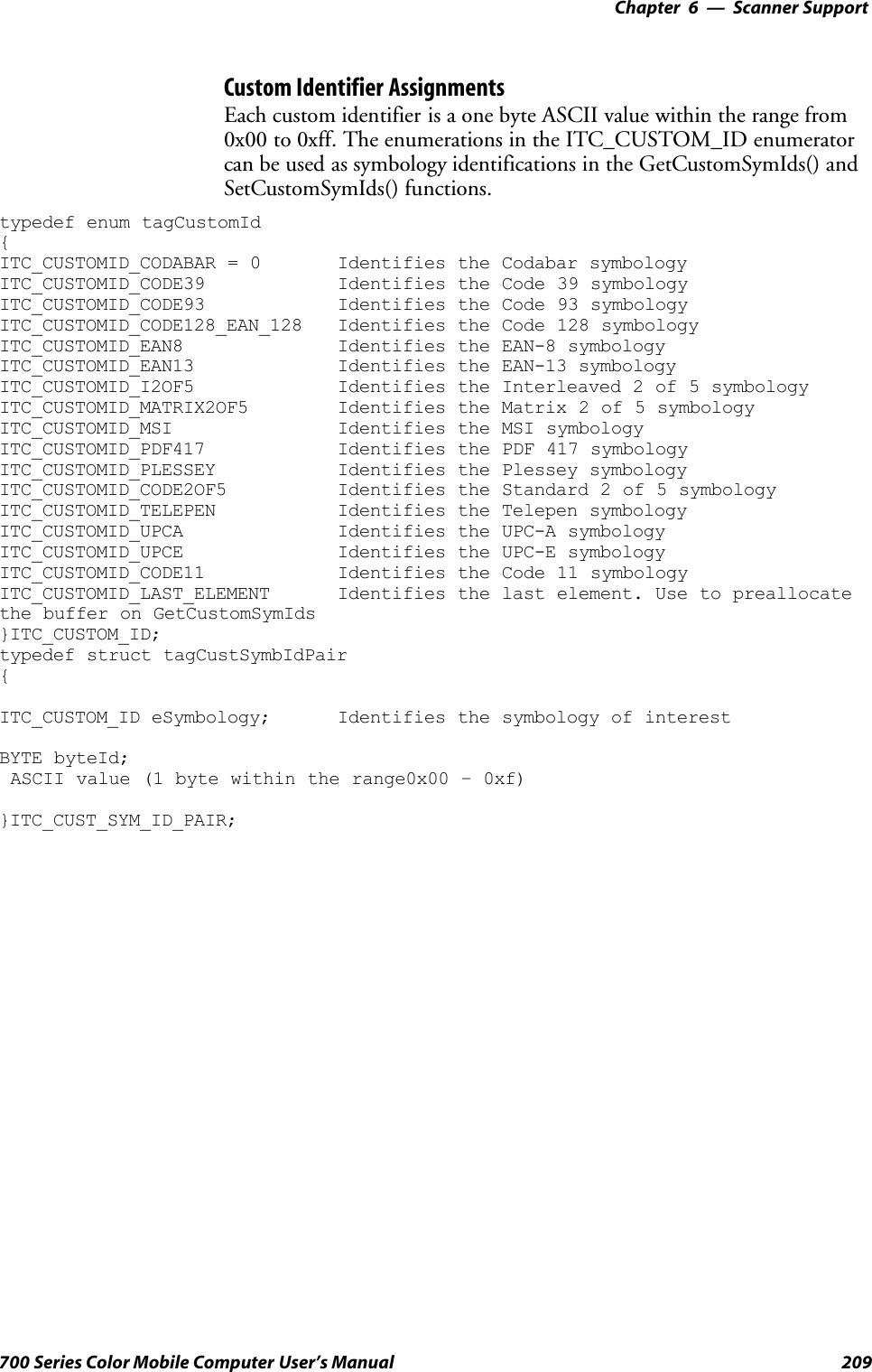
![6 Scanner Support—Chapter207700 Series Color Mobile Computer User’s ManualIS9CConfig2::GetCustomSymIdsThis function retrieves all the custom symbology identifiers defined for thecurrently supported symbologies. This is not supported when using an imag-er on the 700 Series Computer.SyntaxHRESULT GetCustomSymIds( ITC_CUST_SYM_ID_PAIR*pStructSymIdPair,DWORD dwMaxNumElement, DWORD* pdwNumElement);ParameterspStructSymIdPair [out] Pointer to ITC_CUST_SYM_ID_PAIRlocation to receive the current definedsymbology identifiers for the supportedsymbologies. The caller must preallocatethis buffer with dwMaxNumElementelements.dwMaxNumElement [in] Maximum number of elements allocatedfor the pStructSymIdPair buffer whichshould always be equal to the last definedenumeration constant + 1 of theenumeration ITC_CUSTOM_ID. In thiscase, it isITC_CUSTOMID_LAST_ELEMENT.pdwNumElement [out] Pointer to DWORD location to receivethe actual number of elements returned inthe pStructSymIdPair buffer, which shouldbe the same as dwMaxNumElement.Return ValuesHRESULT that indicates success or failure.RemarksNone.See AlsoSCustom Identifier Assignments (page 209)SCustom Identifier Example (page 210)SCustom Identifier Default Settings (page 210)](https://usermanual.wiki/Intermec-Technologies/SB555.Item-5-from-FCC-email-Feb-07-2003/User-Guide-307179-Page-224.png)
![Scanner SupportChapter —6208 700 Series Color Mobile Computer User’s ManualIS9CConfig2::SetCustomSymIdsThis function updates the symbology identifiers (any ASCII values) for thecurrently supported symbologies. This is not supported when using an imag-er on the 700 Series Computer.SyntaxHRESULT SetCustomSymIds( ITC_CUST_SYM_ID_PAIR*pStructSymIdPair, DWORD dwNumElement );ParameterspStructSymIdPair [in] Pointer to ITC_CUST_SYM_ID_PAIRlocation, containing the new symbologyidentifiers for any supported symbologies toupdate.dwNumElement [in] Identifies the number of symbology identifiersto update in the pStructSymIdPair buffer.Return ValuesHRESULT that indicates success or failure.RemarksNone.See AlsoNone.](https://usermanual.wiki/Intermec-Technologies/SB555.Item-5-from-FCC-email-Feb-07-2003/User-Guide-307179-Page-225.png)
![Scanner SupportChapter —6210 700 Series Color Mobile Computer User’s ManualCustom Identifier Default SettingsSymbology Default Valid RangeCodabar D0x00-0xFFCode 11 *0x00-0xFFCode 39 *0x00-0xFFCode 93 D0x00-0xFFCode128/EAN 128 D0x00-0xFFEAN-8 0xFF 0x00-0xFFEAN-13 F0x00-0xFFInterleaved 2 of 5 I0x00-0xFFMatrix 2 of 5 D0x00-0xFFMSI D0x00-0xFFPDF 417 *0x00-0xFFPlessey D0x00-0xFFStandard 2 of 5 D0x00-0xFFTelepen *0x00-0xFFUPC-A A0x00-0xFFUPC-E E0x00-0xFFCustom Identifier ExampleThe following code segment is an example of updating the UPC-E andUPC-A symbology identifiers with new values, and then retrieving thecurrently defined symbology identifiers for all the supported symbologies:ITC_CUST_SYM_ID_PAIR oStructSymIdPair [ITC_CUSTOMID_LAST_ELEMENT];oStructSymIdPair[0].eSymbology = ITC_CUSTOMID_UPCE;oStructSymIdPair[0].byteId = 0x41; // ASCII char AoStructSymIdPair[1].eSymbology = ITC_CUSTOMID_UPCA;oStructSymIdPair[1].byteId = 0x42; // ASCII char BHRESULT hr = pIS9CConfig2->SetCustomSymIds(&oStructSymIdPair[0], 2];DWORD dwNum = 0;HRESULT hr = pIS9CConfig2->GetCustomSymIds(&oStructSymIdPair[0],ITC_CUSTOMID_LAST_ELEMENT, &dwNum);](https://usermanual.wiki/Intermec-Technologies/SB555.Item-5-from-FCC-email-Feb-07-2003/User-Guide-307179-Page-227.png)
![6 Scanner Support—Chapter211700 Series Color Mobile Computer User’s ManualIS9CConfig2::GetGlobalAmbleThis retrieves the scanner’ s current preamble or postamble setting.SyntaxHRESULT GetGlobalAmble( ITC_GLOBAL_AMBLE_ID eAmbleId, BYTErgbBuffer[], DWORD dwBufferSize, DWORD* pdwBufferSize );ParameterseAmbleId [in] An enumeration of typeITC_GLOBAL_AMBLE_ID identifies whetherthe preamble or postamble setting is to beretrieved. Only one setting can be queried at atime.rgbBuffer [in] Contains the buffer for the postamble orpreamble setting to be queried.dwBufferSize [in] The maximum number of bytes that rgbBuffercan store. Must be at leastITC_GLOBAL_AMBLE_MAX_CHARS bytes.pdwBufferSize [out] A pointer to DWORD location to store theactual number of returned bytes in rgbBuffer.Return ValuesHRESULT that indicates success or failure.RemarksNone.See AlsoNone.](https://usermanual.wiki/Intermec-Technologies/SB555.Item-5-from-FCC-email-Feb-07-2003/User-Guide-307179-Page-228.png)
![Scanner SupportChapter —6212 700 Series Color Mobile Computer User’s ManualIS9CConfig2::SetGlobalAmbleThis function updates the scanner’ s current preamble or postamble settingdepending on the input parameters.SyntaxHRESULT SetGlobalAmble( ITC_GLOBAL_AMBLE_ID eAmbleId, BYTErgbBuffer[], DWORD dwBufferSize );ParameterseAmbleId [in] An enumeration of typeITC_GLOBAL_AMBLE_ID identifies whetherthe preamble or postamble setting is to be updated.Only one setting can be updated at a time.rgbBuffer [in] Contains the buffer for the postamble or preamblesetting to be updated.dwBufferSize [in] Identifies number of bytes in rgbBuffer.Return ValuesHRESULT that indicates success or failure.RemarksNone.See AlsoNone.Postamble and Preamble DefaultsParameter Default Valid RangePreamble Null 0to20ASCIIcharactersPostamble Null 0to20ASCIIcharacters](https://usermanual.wiki/Intermec-Technologies/SB555.Item-5-from-FCC-email-Feb-07-2003/User-Guide-307179-Page-229.png)
![6 Scanner Support—Chapter213700 Series Color Mobile Computer User’s ManualIS9CConfig2::GetPDF417ExtThis function is an extended function for retrieving the PDF 417 settingsnot included in the IS9CConfig::GetPDF417.SyntaxHRESULT GetPDF417Ext( ITC_MICRO_PDF417_DECODING* peDecode,ITC_MICRO_PDF417_CODE128_EMULATION* peCode128 );ParameterspeDecode [out] Pointer to ITC_MICRO_PDF417_DECODINGlocation to receive the Micro PDF 417 decoding.peCode128 [out] Pointer toITC_MICRO_PDF417_CODE128_EMULATION*location to receive the Micro PDF 417 Code 128emulation option.Return ValuesHRESULT that indicates success or failure.RemarksNone.See AlsoNone.IS9CConfig2::SetPDF417ExtThis function is an extended function for updating the additional PDF417 settings not included in IS9CConfig::SetPDF417.SyntaxHRESULT SetPDF417Ext( ITC_MICRO_PDF417_DECODING eDecode,ITC_MICRO_PDF417_CODE128_EMULATION eCode128 );ParameterseDecode [in] An enumeration that identifies decoding option for theMicro PDF 417.eCode128 [in] An enumeration that identifies the Code 128 emulationoption for the Micro PDF 417.Return ValuesHRESULT that indicates success or failure.RemarksNone.See AlsoNone.](https://usermanual.wiki/Intermec-Technologies/SB555.Item-5-from-FCC-email-Feb-07-2003/User-Guide-307179-Page-230.png)
![Scanner SupportChapter —6214 700 Series Color Mobile Computer User’s ManualPDF 417 Extended: Micro PDF 417 Default SettingsParameter Default Valid RangeDecoding Not Active ITC_MICRO_PDF417_DECODINGCode 128 Emulation Not Active ITC_MICRO_PDF417_CODE128_EMULATION* These are Micro PDF 417 parameters.IS9CConfig2::GetSymIdXmitThis function retrieves the current symbology ID transmission option asdescribed on the next page.SyntaxHRESULT GetSymIdXmit( ITC_SYMBOLOGY_ID_XMIT* peSymIdXmit );ParameterspeSymIdXmit [out] Pointer to ITC_SYMBOLOGY_ID_XMITlocation to receive the current symbologyidentifier transmission option.Return ValuesHRESULT that indicates success or failure.RemarksNone.See AlsoNone.IS9CConfig2::SetSymIdXmitThis updates the symbology ID transmission option shown next page.SyntaxHRESULT SetSymIdXmit( ITC_SYMBOLOGY_ID_XMIT eSymIdXmit );ParameterseSymIdXmit [in] Identifies the symbology identifier transmissionoption to update.Return ValuesHRESULT that indicates success or failure.RemarksNone.See AlsoNone.](https://usermanual.wiki/Intermec-Technologies/SB555.Item-5-from-FCC-email-Feb-07-2003/User-Guide-307179-Page-231.png)
![6 Scanner Support—Chapter215700 Series Color Mobile Computer User’s ManualSymbology ID Transmission OptionThe symbology identifier (or code mark) concept provides a standardizedway for a device receiving data from a bar code reader to differentiate be-tween the symbologies.The following symbology ID transmission option specifies whether or notthe symbology ID should be transmitted as part of the scanned bar codelabel to all the connected data collection applications. Options for trans-mission are: do not transmit, transmit the standard AIM identifiers, ortransmit the one byte custom defined identifiers. AIM and custom identi-fiers cannot be selected to be transmitted at the same time; only the lastselected option will be active.typedef enum tagSymbologyIdXmit{ITC_ID_XMIT_DISABLE = 0 Symbology identifier will not be transmitted as part of thelabel. This is the default setting.ITC_ID_XMIT_CUSTOM = 1 Activate custom symbology identifier transmission for allsymbologies. Example of the transmitted label:[preamble] [Custom ID] <data> [postamble]ITC_ID_XMIT_AIM = 2 Activate AIM symbology identifier transmission for allsymbologies. Example of the transmitted label:[preamble] [AIM symbology ID] <data> [postamble]}ITC_SYMBOLOGY_ID_XMIT;](https://usermanual.wiki/Intermec-Technologies/SB555.Item-5-from-FCC-email-Feb-07-2003/User-Guide-307179-Page-232.png)
![Scanner SupportChapter —6216 700 Series Color Mobile Computer User’s ManualIS9CConfig3 FunctionsThe IS9CConfig3 interface provides generic methods for retrieving andsetting configuration using ISCP commands.ISCP CommandsAn ISCP Command is composed of three or more bytes formatted as<SG><FID><parameters> where:SSG Setup group.SFID Function ID.Sparameters One or more configuration value bytes depending on theconfiguration.ISCP commands include the following:Imager SettingsThis dictates the start and end column positions for the image dimension.SG FID Parameter Description0x7B 80 Value [0..639] Start column position.0x7B 81 Value [0..639] End column position.Trigger SettingsThis sets the duration of the aiming beam before acquiring images to bedecoded.SG FID Parameter Description0x70 81 Value [0..65535] Number of milliseconds.QRCode SymbologyThis enables or disables the QRCode symbology.SG FID Parameter Description0x55 40 0 Disable this symbology.0x55 40 1 Enable this symbology.Data Matrix SymbologyThis enables or disables the Data Matrix symbology.SG FID Parameter Description0x54 40 0 Disable this symbology.0x54 40 1 Enable this symbology.](https://usermanual.wiki/Intermec-Technologies/SB555.Item-5-from-FCC-email-Feb-07-2003/User-Guide-307179-Page-233.png)
![6 Scanner Support—Chapter217700 Series Color Mobile Computer User’s ManualISCP::GetConfigThis retrieves configurations using the ISCP commands format.SyntaxHRESULT ISCPGetConfig( BYTE rgbCommandBuff[], DWORDdwCommandBuffSize, BYTE rgbReplyBuff[], DWORDdwReplyBuffMaxSize, DWORD *pdwReplyBuffSize );ParametersrgbCommandBuff [in, size_is] Contains ISCP commands inarray of bytes.dwCommandBuffSize [in] Number of bytes inrgbCommandBuff.rgbReplyBuff [in, out, size_is] Results of query in array ofbytes.dwReplyBuffMaxSize [in] Maximum size of rgdReplyBuff.pdwReplyBuffSize [in, out] Number of bytes placed inrbfReplyBuff.Return ValuesNone.RemarksNone.See AlsoNone.](https://usermanual.wiki/Intermec-Technologies/SB555.Item-5-from-FCC-email-Feb-07-2003/User-Guide-307179-Page-234.png)
![Scanner SupportChapter —6218 700 Series Color Mobile Computer User’s ManualISCP::SetConfigThis updates configurations using the ISCP commands format.SyntaxHRESULT ISCPSetConfig( BYTE rgbCommandBuff[], DWORDdwCommandBuffSize, BYTE rgbReplyBuff[], DWORDdwReplyBuffMaxSize, DWORD *pdwReplyBuffSize );ParametersrgbCommandBuff [in, size_is] Contains ISCP commands inarray of bytes.dwCommandBuffSize [in] Number of bytes inrgbCommandBuff.rgbReplyBuff [in, out, size_is] Results of request in array ofbytes.dwReplyBuffMaxSize [in] Maximum size of rgbReplyBuff.pdwReplyBuffSize [in, out] Number of bytes placed inrgbReplyBuff.Return ValuesNone.RemarksNone.See AlsoNone.](https://usermanual.wiki/Intermec-Technologies/SB555.Item-5-from-FCC-email-Feb-07-2003/User-Guide-307179-Page-235.png)
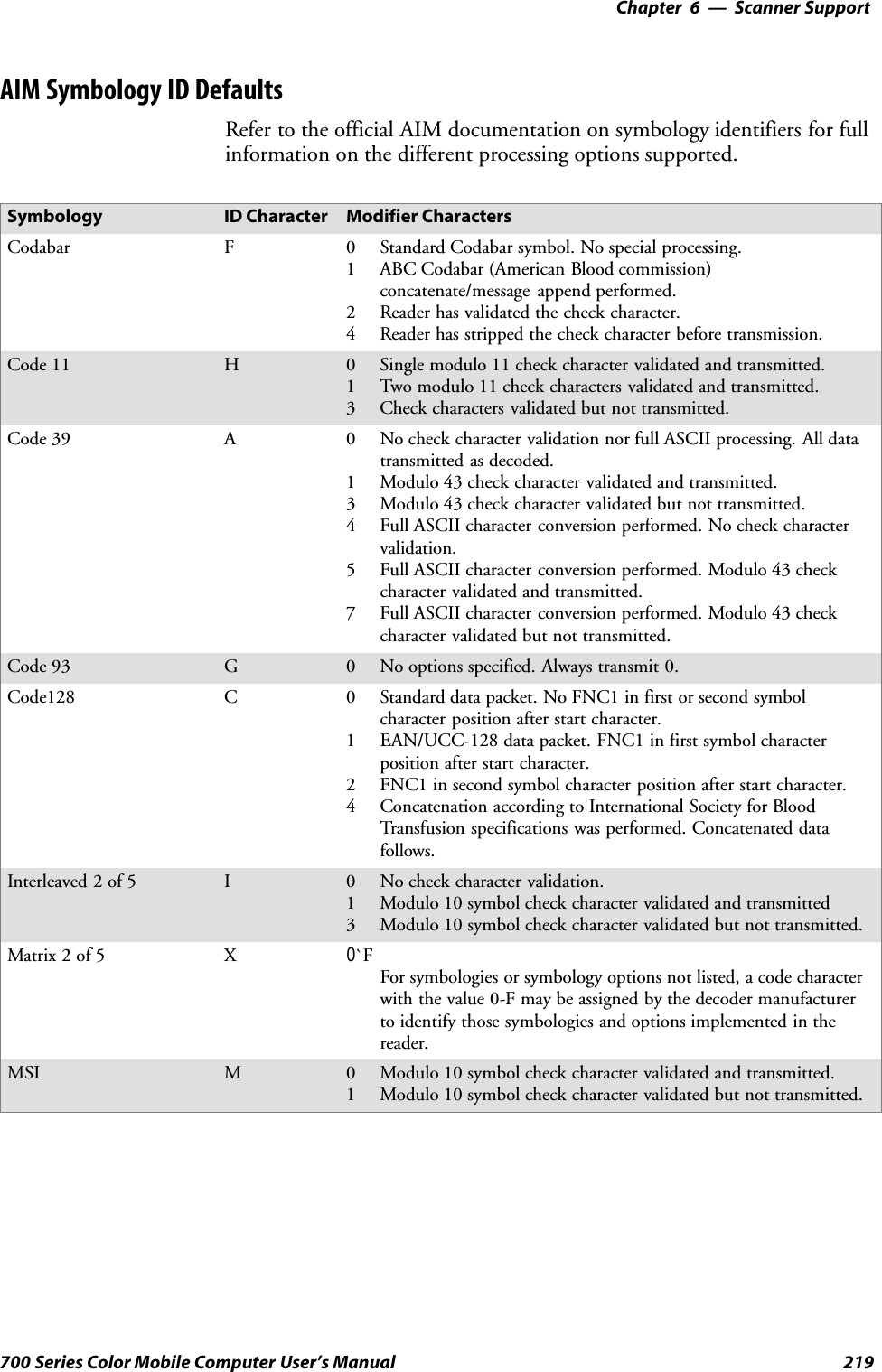
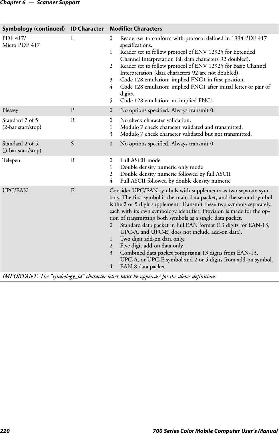
![6 Scanner Support—Chapter221700 Series Color Mobile Computer User’s ManualIImage InterfaceThe IImage interface gives the application the capability to acquire images.The image acquired can be either a raw image as captured by the digitalcamera or it can be normalized. A normalized image is presented the sameas if the picture were taken at right angles to the image and at the samedistance. The normalized image is commonly used for signature captureapplications.SIImage::ReadSigCapBuffer (page 221)SIImage::ReadSigCapFile (page 224)SIImage::ReadImage (page 225)SIImage::CancelReadImage (page 226)SIImage::Start (page 226)SIImage::Stop (page 227)SIImage::Open (page 227)SIImage::Close (page 228)IImage::ReadSigCapBufferSyntaxHRESULT IImage::ReadSigCapBuffer( ITC_SIGCAP_SPEC*pSigCapSpec, ITC_IMAGE_SPEC *pImgBuffer, DWORD nMaxBuffSize);ParametersParameters:pSigCapSpec [in] Pointer to the structure that identifies the signaturecapture region. This structure is defined as follows:typedef struct tagITCSigCapSpec{DWORD dwStructSize;INT iAspectRatio;INT iOffsetX;INT iOffsetY;UINT uiWidth;UINT uiHeight;INT iResolution;ITCFileFormat eFormat;DWORD eDepth;} ITC_SIGCAP_SPEC;where:SdwStructSize Size, in bytes, of this struct. This is for version control.SiAspectRatio Ratio of the bar code height (linear bar codes) or rowheight (2D bar codes) to the narrow element width.SiOffsetX Offset in X direction, relative to barcode center.Positive values are right of the bar code, negativevalues to the left.](https://usermanual.wiki/Intermec-Technologies/SB555.Item-5-from-FCC-email-Feb-07-2003/User-Guide-307179-Page-238.png)
![Scanner SupportChapter —6222 700 Series Color Mobile Computer User’s ManualSiOffsetY Offset in Y direction, relative to barcode center.Positive values are higher than the bar code, negativevalues lower.SuiWidth Width of signature capture image region in intelligentbar code units.SuiHeight Height of the signature capture image region inintelligent bar code units.SiResolution Number of pixels per intelligent bar code unit.SeFormat Format of the image buffer returned as follows.Currently, only ITC_FILE_RAW is supported.ITC_FILE_KIM = 0, // Returns data a KIM fileITC_FILE_TIFF_BIN = 1, // TIFF Binary fileITC_FILE_TIFF_BIN_GROUP4 = 2, // TIFF Binary Group 4 compressedITC_FILE_TIFF_GRAY_SCALE = 3, // TIFF Gray ScaleITC_FILE_RAW = 4, // Raw imageITC_FILE_JPEG = 5, // JPEG imageSeDepth Number of bits per pixel. Currently, only one(monochrome) or eight (gray-scale) are supported.pImgBuffer [out] Pointer to the buffer in which the signature captureimage will be put.typedef struct tagITCImageSpec{DWORD dwStructSize;LONG biWidth;LONG biHeight;WORD biBitCount;ITC_FILE_FORMAT eFormat;DWORD biActualImageSize;DWORD biMaxImageBytes;BYTE rgbImageData[1];} ITC_IMAGE_SPEC;where:SdwStructSize Size, in bytes, of this struct. This is for versioncontrol.SbiWidth The width of each row in pixels.SbiHeight The number of rows in the image data.SbiBitCount The number of bits per pixel.SeFormat Identifies the image format.SbiActualImageSize Total bytes of image data returned.SbiMaxImageBytes Maximum bytes that can be stored inrgbImageData[].SrgbImageData Buffer containing the actual data, for example a640x480 uses a 307200-byte buffer. The array sizeof this buffer is arbitrary so do not use thisstructure directly to reserve memory. The actualdimension of the buffer is identified bybiMaxImageBytes.](https://usermanual.wiki/Intermec-Technologies/SB555.Item-5-from-FCC-email-Feb-07-2003/User-Guide-307179-Page-239.png)
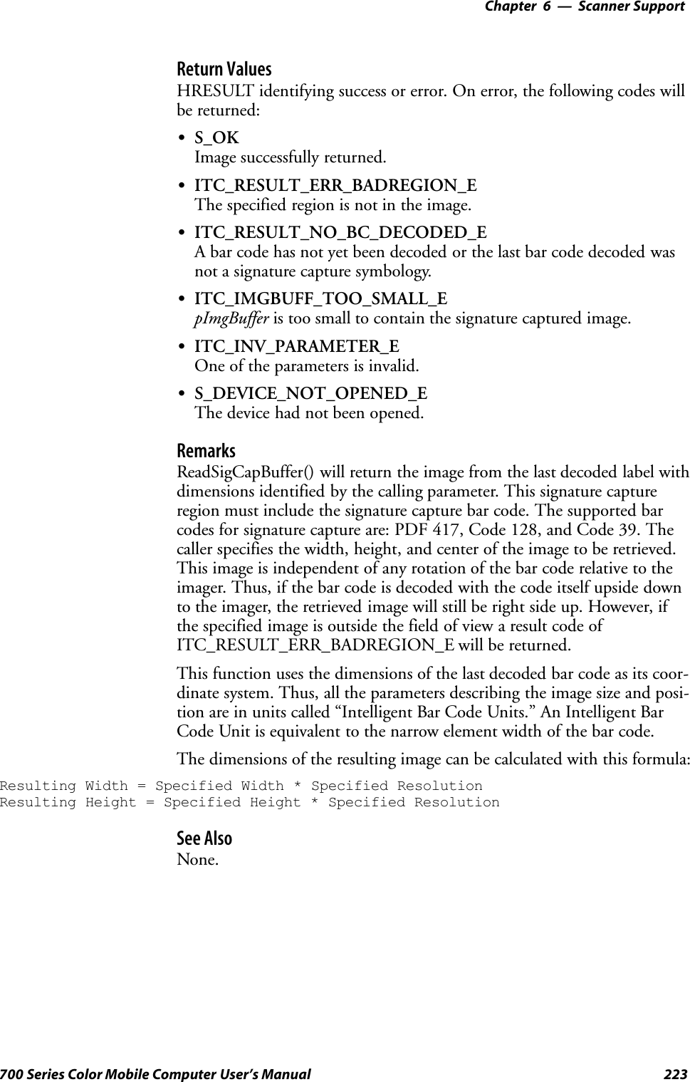
![Scanner SupportChapter —6224 700 Series Color Mobile Computer User’s ManualIImage::ReadSigCapFileNote: This has not been implemented as of this publication.SyntaxHRESULT IImage::ReadSigCapFile( ITC_SIGCAP_SPEC*pSigCapSpec, LPCTSTR pszFileName );ParameterspSigCapSpec [in] Pointer to the structure that identifies the signaturecapture region. See ReadSigCapFile (page 221) fora description of this structure.pszFileName [in] Name of the file in which to copy the image.Return ValuesHRESULT identifying success or error. On error, the following codes willbe returned:SS_OKImage successfully returned.SITC_RESULT_ERR_BADREGION_EThe specified region is not in the image.SITC_RESULT_NO_BC_DECODED_EA bar code has not yet been decoded or the last bar code decoded wasnot a signature capture symbology.SITC_FILE_OPEN_EThe file could not be opened.SITC_INV_PARAMETER_EOne of the parameters is invalid.SS_DEVICE_NOT_OPENED_EThe device had not been opened.RemarksReadSigCapFile() will write the image from the last decoded label with di-mensions identified by the calling parameter. If the file already exists, itscontents will be overwritten.This signature capture region must include the signature capture bar code.The supported bar codes for signature capture are: PDF 417, Code 128,and Code 39. The caller specifies the width, height, and center of theimage to be retrieved. This image is independent of any rotation of the barcode relative to the imager. Thus, if the bar code is decoded with the codeitself upside down to the imager, the retrieved image will still be right sideup. However, if the specified image is outside the field of view a resultcode of ITC_RESULT_ERR_BADREGION_E will be returned.This function uses the dimensions of the last decoded bar code as its coor-dinate system. Thus, all the parameters describing the image size and posi-tion are in units called “Intelligent Bar Code Units”. An Intelligent BarCode Unit is equivalent to the narrow element width of the bar code.](https://usermanual.wiki/Intermec-Technologies/SB555.Item-5-from-FCC-email-Feb-07-2003/User-Guide-307179-Page-241.png)
![6 Scanner Support—Chapter225700 Series Color Mobile Computer User’s ManualThe dimensions of the resulting image can be calculated with this formula:Resulting Width = Specified Width * Specified ResolutionResulting Height = Specified Height * Specified ResolutionSee AlsoNone.IImage::ReadImageSyntaxHRESULT IImage::Read( ITCFileFormat eFormat, DWORD nDepth,ITC_IMAGE_SPEC *pImgBuffer, DWORD dwTimeout );ParameterseFormat [in] Format of the image buffer returned as follows.Currently, only ITC_FILE_RAW is supported.ITC_FILE_KIM = 0, // Returns data a KIM fileITC_FILE_TIFF_BIN = 1, // TIFF Binary fileITC_FILE_TIFF_BIN_GROUP4 = 2, // TIFF Binary Group 4 compressedITC_FILE_TIFF_GRAY_SCALE = 3, // TIFF Gray ScaleITC_FILE_RAW = 4, // Raw imageITC_FILE_JPEG = 5, // JPEG imagenDepth [in] Number of bits per pixel. Currently, only eight(gray-scale) are supported.pImgBuffer [in/out] Pointer to the buffer containing the image.dwTimeout [in] Milliseconds to wait for the image to be returned.Return ValuesHRESULT identifying success or error. On error, these will be returned:SS_OK Image successfully returned.SITC_IMGBUFF_TOO_SMALL_E pImgBuffer is too small to containthe signature captured image.SITC_TIMEOUT_E Timeout.SITC_INV_PARAMETER_E One of the parameters is invalid.SS_DEVICE_NOT_OPENED_E The device had not been opened.RemarksThe image is returned in pImgBuffer in the caller specified format.See AlsoNone.](https://usermanual.wiki/Intermec-Technologies/SB555.Item-5-from-FCC-email-Feb-07-2003/User-Guide-307179-Page-242.png)
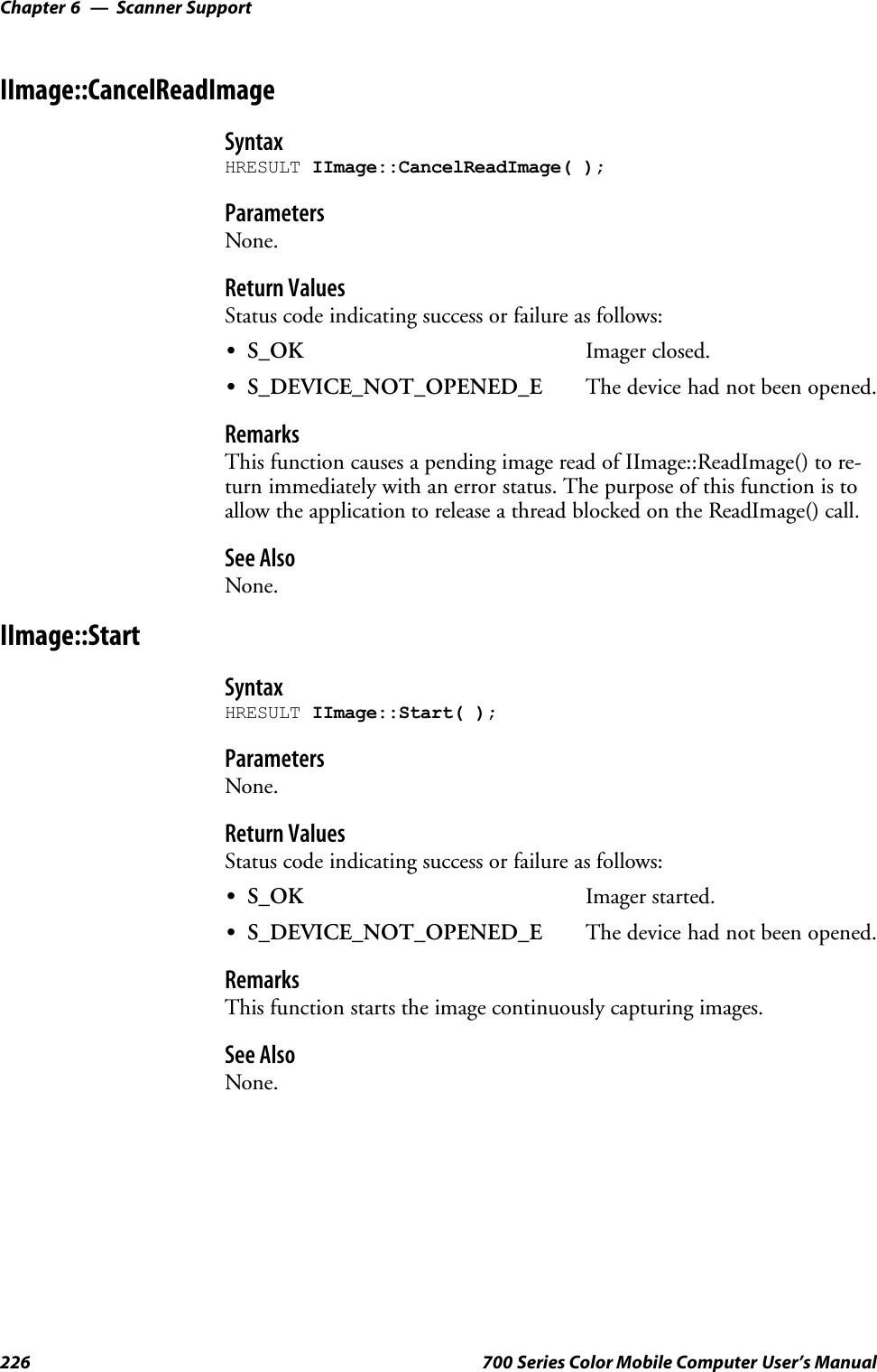
![6 Scanner Support—Chapter227700 Series Color Mobile Computer User’s ManualIImage::StopSyntaxHRESULT IImage::Stop( );ParametersNone.Return ValuesStatus code indicating success or failure as follows:SS_OK Imager started.SS_IMG_NOT_PRESENT_E Unit does not contain an imager.SS_DEVICE_NOT_OPENED_E Device had not been opened.RemarksThis function stops the image continuously capturing images.See AlsoNone.IImage::OpenSyntaxHRESULT IImage::Open( BOOL fSigCapEnable );ParametersfSigCapEnable [in] When TRUE, signature capture is enabled. WhenFALSE, it is disabled. Bar code labels are decodedand images (via IImage::ReadImage) the same.Return ValuesStatus code indicating success or failure as follows:SS_OK Imager opened.SS_IMG_NOT_PRESENT_E Unit does not contain an imager.SS_DEVICE_CONTENTION_E Device has already been opened.RemarksThis function exclusively allocates the imager device so that the other IIm-age methods can be safely called.See AlsoNone.](https://usermanual.wiki/Intermec-Technologies/SB555.Item-5-from-FCC-email-Feb-07-2003/User-Guide-307179-Page-244.png)
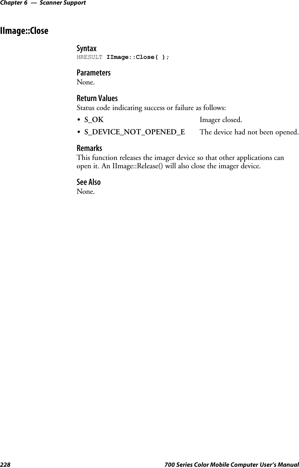
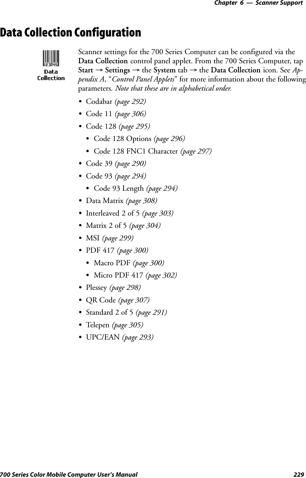
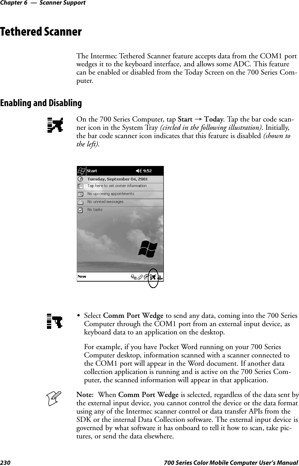
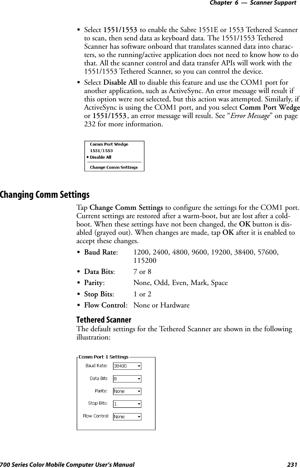
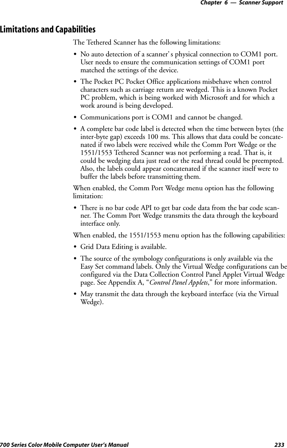
![Scanner SupportChapter —6234 700 Series Color Mobile Computer User’s ManualSThe bar code APIs, defined in the IADC interface, are available to getbar code data from the bar code scanner. The following example showshow to programmatically collects bar code data:#include “IADC.h” // Linked with ITCUUID.LIB#include “ITCAdcMgmt.h” // Linked with ITCAdcDevMgmt.libIADC* pIADC;HRESULT hrStatus = S_OK;// Create a ADC COM interface to collect bar code data from the 1551E/1553// when the 1551/1553 menu option is enabled.hrStatus =ITCDeviceOpen(TEXT(“ExtScanner”), // Name of the ADC device.IID_IADC, // COM interface to returnITC_DHDEVFLAG_READAHEAD, // Device’s Flags(LPVOID *) &pIADC); // the returned interfaceif( SUCCEEDED(hrStatus) ){BYTE byteBuffer[MAX_LABEL_SIZE];DWORD dwLength = 0;HRESULT hr = pIDC->Read(byteBuffer, // Buffer to put the ADC data.MAX_LABEL_SIZE, // Size of pDataBuffer in bytes.&dwLength, // Number bytes returned.NULL, // Time stamp of the received data. NULL.INFINITE // Number of milliseconds to wait.);}when done using this COM interface, delete it:ITCDeviceClose( (IUnknown **) pIADC);](https://usermanual.wiki/Intermec-Technologies/SB555.Item-5-from-FCC-email-Feb-07-2003/User-Guide-307179-Page-251.png)