Intermec Technologies SB555-2 SB555 Radio in 700C User Manual Exhibit L
Intermec Technologies Corporation SB555 Radio in 700C Exhibit L
Contents
User Manual Part 1 of 2
Exhibit L: User Manual - Part 1 of 2
FCC ID: HN2SB555-2
P/N 072719-002
Important Radio Information!
Contents
For Users in the United States and Canada ...................................................................................................................................2
For 700C-802.11b Configuration...................................................................................................................................2
For ABTM3 (Bluetooth-Compatible Wireless Module by Socket Communications) Configuration ...............................2
For MC45 (Wireless WAN, GSM/GPRS) Configuration...............................................................................................3
For SB555 (Wireless WAN, CDMA/1x) Configuration..................................................................................................3
For Users Outside of the United States and Canada......................................................................................................................4
For 700C-802.11b Configuration...................................................................................................................................4
For ABTM3 (Bluetooth-Compatible Wireless Module by Socket Communications) Configuration ...............................5
For MC45 (Wireless WAN, GSM/GPRS) Configuration...............................................................................................6
Pour les utilisateurs en dehors du Canada et des Etat-unis .............................................................................................................7
Pour la configuration 700C-802.11b ..............................................................................................................................7
Pour la configuration ABTM3 (Module sans fil compatible avec la norme Bluetooth de Socket Communications).........8
Pour la configuration MC45...........................................................................................................................................8
Für Benutzer außerhalb von Kanada und den Vereinigten Staaten ................................................................................................9
700C-802.11b................................................................................................................................................................9
ABTM3 (Bluetooth-kompatibles Funkmodul von Socket Communications)................................................................10
MC45 ..........................................................................................................................................................................10
Per gli utenti al di fuori del Canada o degli Stati Uniti ................................................................................................................11
Per la configurazione di 700C-802.11b.........................................................................................................................11
Per la configurazione di ABTM3 (modulo wireless Bluetooth-compatibile della Socket Communications)....................11
Per la configurazione di MC45 .....................................................................................................................................12
Para Usuarios Fuera de Canada o de los Estados Unidos .............................................................................................................12
Para configuração do 700C-802.11b.............................................................................................................................12
Para configuração do ABTM3 (Módulo sem fio compatível com Bluetooth da Socket Communications) .....................13
Para configuração do MC45 .........................................................................................................................................14
Para Usuários Fora do Canadá ou dos Estados Unidos ................................................................................................................14
Para la configuración de 700C-802.11b........................................................................................................................14
Para la configuración de ABTM3 (Módulo inalámbrico compatible con Bluetooth de Socket Communications)..........15
Para la configuración de MC45.....................................................................................................................................16

2
For Users in the United States and Canada
Place this supplement in your manual.
For 700C-802.11b Configuration
This device complies with Part 15 of the FCC Rules and with RSS-210 of Industry Canada. Operation is subject to
the following two conditions: (1) This device may not cause harmful interference, and (2) This device must accept any
interference received, including interference that can cause undesired operation.
Federal Communications Commission Compliance
FCC Digital Emissions Compliance: This equipment has been tested and found to comply with the limits for a
Class B digital device, pursuant to Part 15 of the FCC Rules. These limits are designed to provide reasonable
protection against harmful interference in a residential installation. This equipment generates, uses, and can radiate
radio frequency energy and, if not installed and used in accordance with the instructions, may cause harmful
interference to radio communications. However, there is no guarantee that interference will not occur in a particular
installation. If this equipment does cause harmful interference to radio or television reception, which can be
determined by turning the equipment off and on, the user is encouraged to try to correct the interference by one or
more of the following measures:
• Reorient or relocate the radio or television receiving antenna.
• Increase the separation between the computer equipment and receiver.
• Connect the equipment to an outlet on a circuit different from that to which the radio or television receiver is
connected.
• Consult the dealer or an experienced radio television technician for help.
Operation Warning: To comply with the FCC’s RF exposure requirements and minimize health
hazards:
• The user shall not touch the antenna of this device when the device is in use.
Changes or modifications not expressly approved by Intermec could void the user’s authority to
operate this equipment.
Industry Canada Compliance
This Class B digital apparatus meets all requirements of the Canadian Interference-Causing Equipment Regulations.
This device requires a radio license unless it is used totally inside a building. (The user must obtain this license.)
Cet appareil numérique de la classe B respecte toutes les exigences du Règlement sur le matériel brouilleur du Canada.
Cet appareil exige une license radio à moins d’être entièrement installé dans un bâtiment. (L’utilisateur doit obtenir
cette license.)
Agency Approvals
This device is UL Listed.
For ABTM3 (Bluetooth-Compatible Wireless Module by Socket Communications)
Configuration
This device complies with Part 15 of the FCC rules and with RSS-210 of Industry Canada.
Cet appareil est conforme à la Partie 15 des règlements du FCC et à la norme RSS-210 d’Industrie Canada.

3
Operation Warning: To comply with the FCC’s RF exposure requirements and minimize health
hazards:
• The user shall not touch the antenna of this device when the device is in use.
Changes or modifications not expressly approved by Intermec could void the user’s authority to
operate this equipment.
This device requires a radio license unless it is used totally inside a building. (The user must obtain this license.)
Cet appareil exige une license radio à moins d’être entièrement installé dans un bâtiment. (L’utilisateur doit obtenir
cette license.)
Agency Approvals
This device is UL Listed.
For MC45 (Wireless WAN, GSM/GPRS) Configuration
This device complies with Part 24 of the FCC Rules and with RSS-133 of Industry Canada.
Cet appareil est conforme à la Partie 24 des règlements du FCC et à la norme RSS-133 d’Industrie Canada.
Antennas must be supplied and installed as recommended by Intermec Technologies Corporation to
ensure compliance to RF exposure requirements.
The user shall not touch the antenna of this device when the device is in use.
Agency Approvals: See user’s guide instructions for handling, charging, and replacing batteries.
Failure to follow those instructions can result in personal injury, fire, or battery explosion.
For SB555 (Wireless WAN, CDMA/1x) Configuration
This device complies with Parts 22 and 24 of the FCC Rules and with RSS-1383 of Industry Canada.
Cet appareil est conforme aux Parties 22 et 24 des règlements du FCC et à la norme RSS-1383 d’Industrie Canada.
Antennas must be supplied and installed as recommended by Intermec Technologies Corporation to
ensure compliance to RF exposure requirements.
Agency Approvals: See user’s guide instructions for handling, charging, and replacing batteries.
Failure to follow those instructions can result in personal injury, fire, or battery explosion.

4
For Users Outside of the United States and Canada
Place this supplement in your manual.
For 700C-802.11b Configuration
The Intermec product you purchased transmits and receives data using a 2.4 GHz Direct Sequence Spread Spectrum
system.
Programming and configuration information for the transceivers is also provided in the host device documentation.
Please check the Intermec Web site for additional documentation at www.intermec.com.
Hereby, Intermec Technologies Corporation declares that this Model 700C-802.11b is in compliance with the
essential requirements and other relevant provisions of R&TTE Directive (1999/5/EC). This product has been
assessed to the following standards:
• ETSI EN 300 328-2 v1.2.1 (2001-12)
• ETSI EN 301 489-17 v1.1.1 (2001-09)
• EN 60950:1992 (incl. Amdt. 1-4, 11)
• SP/DGPT/ATAS 23 (1995-02)
The original Declaration of Conformity is available on the Intermec Technologies Corporation Web site at
www.intermec.com.
This product transmits electromagnetic waves at 2.4 GHz frequency range. It has been tested and found compliant
with U.S. (OET Guide 65) and Canadian (RSS 102) RF exposure regulations. There are no regulations covering this
product type in the EU at this time.
The transmitter module’s output power is 89 mW. The products using this module are intended for business and
industrial environments. They should not be used in residential environments and by children.
This product is marked with this logo and uses radio frequency bands that are not harmonized
throughout the European Community.
The following table indicates the areas of intended use of the equipment and any known restrictions.
Country of Intended Use License
Yes No Required Restrictions Details
Austria X
Belgium X
Denmark X
Finland X
France X X Frequency operation restricted to 2446.5 MHz to 2483.5 MHz.
Germany X
Greece X
Ireland X
Italy X
Luxembourg X
The Netherlands X
Portugal X
Spain X
Sweden X
United Kingdom X

5
Country of Intended Use License
Yes No Required Restrictions Details
Other non-EU:
Iceland X
Liechtenstein X
Norway X
Slovenia X
Switzerland X
Additional EMI/RFI Compliance
This device meets the Class B limit requirements of CISPR 22.
For ABTM3 (Bluetooth-Compatible Wireless Module by Socket Communications)
Configuration
The Intermec product you purchased transmits and receives data using a 2.4 GHz Frequency Hopping Spread
Spectrum system.
Programming and configuration information for the transceivers is also provided in the host device documentation.
Please check the Intermec Web site for additional documentation at www.intermec.com.
Hereby, Intermec Technologies Corporation declares that this Model 700C-ABTM3 is in compliance with the
essential requirements and other relevant provisions of R&TTE Directive (1999/5/EC). This product has been
assessed to the following standards:
• ETSI EN 300 328-2 v1.2.1 (2001-12)
• ETSI EN 301 489-17 v1.1.1 (2001-09)
• EN 60950:1992 (incl. Amdt. 1-4, 11)
• SP/DGPT/ATAS 23 (1995-02)
The original Declaration of Conformity is available on the Intermec Technologies Corporation Web site at
www.intermec.com.
This product transmits electromagnetic waves at 2.4 GHz frequency range. It has been tested and found compliant
with U.S. (OET Guide 65) and Canadian (RSS 102) RF exposure regulations. There are no regulations covering this
product type in the EU at this time.
The transmitter module’s output power is 1 mW. The products using this module are intended for business and
industrial environments. They should not be used in residential environments and by children.
This product is marked with this logo and uses radio frequency bands that are not harmonized
throughout the European Community.

6
The following table indicates the areas of intended use of the equipment and any known restrictions.
Country of Intended Use License
Yes No Required Restrictions Details
Austria X
Belgium X
Denmark X
Finland X
France X X Frequency operation restricted to 2446.5 MHz to 2483.5 MHz.
Germany X
Greece X
Ireland X
Italy X
Luxembourg X
The Netherlands X
Portugal X
Spain X
Sweden X
United Kingdom X
Other non-EU:
Iceland X
Liechtenstein X
Norway X
Slovenia X
Switzerland X
Additional EMI/RFI Compliance
This device meets the Class B limit requirements of CISPR 22.
For MC45 (Wireless WAN, GSM/GPRS) Configuration
The Intermec product you purchased transmits and receives data using a 900/1800/1900 MHz GSM/GPRS radio
module.
Programming and configuration information for the transceivers is also provided in the host device documentation.
Please check the Intermec Web site for additional documentation at www.intermec.com.
Hereby, Intermec Technologies Corporation declares that this Model 700C-MC45 is in compliance with the essential
requirements and other relevant provisions of R&TTE Directive (1999/5/EC). This product has been assessed to the
following standards:
• ETSI TS 51.010
• ETSI EN 301 489-7 v1.1.1 (2001-09)
• EN 60950:1992 (incl. Amdt. 1-4, 11)
The original Declaration of Conformity is available on the Intermec Technologies Corporation Web site at
www.intermec.com.
This product transmits electromagnetic waves at 900/1800/1900 MHz. It has been tested and found compliant with
U.S. (OET Guide 65), Canadian (RSS 102), European (EN 50360/EN 50361), and Australian/New Zealand
(AS/NZA 2772.1) RF exposure regulations.
7
The transmitter module’s output power is 0.933 mW. The products using this module are intended for business and
industrial environments. They should not be used in residential environments and by children.
This product is marked with this logo.
Additional EMI/RFI Compliance
This device meets the Class B limit requirements of CISPR 22.
Pour les utilisateurs en dehors du Canada et des Etat-unis
Veuillez placer ce supplément dans votre manuel.
Pour la configuration 700C-802.11b
Le produit Intermec que vous avez acheté peut transmettre et recevoir des données à l’aide d’un système d’étalement
du spectre en séquence directe de 2,4 GHz.
Les informations de programmation et de configuration pour les émetteurs-récepteurs sont également fournies dans la
documentation de l’appareil hôte. Pour obtenir toute documentation supplémentaire, veuillez consulter le site Web
d’Intermec, à l’adresse www.intermec.com.
Par la présente, Intermec Technologies Corporation déclare que ce modèle 700C-802.11b est conforme aux exigences
de base et autres exigences pertinentes de la Directive R&TTE (1999/5/EC). Ce produit a été évalué par rapport aux
normes suivantes :
• ETSI EN 300 328-2 v1.2.1 (2001-12)
• ETSI EN 301 489-17 v1.1.1 (2001-09)
• EN 60950:1992 (comprenant l’amendement 1-4, 11)
• SP/DGPT/ATAS 23 (1995-02)
La Déclaration de conformité originale est disponible sur le site Web d’Intermec Technologies Corporation, à l’adresse
www.intermec.com.
Ce produit émet des ondes électromagnétiques à une plage de fréquences de 2,4 GHz. Il a été évalué et reconnu
conforme aux règlements concernant l’exposition à la radiofréquence des États-Unis (OET Guide 65) et du Canada
(RSS 102). Il n’y a actuellement aucun règlement couvrant ce type de produit pour l’Union européenne.
La puissance de sortie du module émetteur-récepteur est de 89 mW. Les produits utilisant ce module sont destinés à
des environnements commerciaux et industriels. Ils ne doivent pas être utilisés dans des environnements résidentiels et
par des enfants.
Ce produit est marqué de ce logo et il utilise des bandes de fréquence radio qui ne sont pas
harmonisées sur le territoire de la Communauté européenne.
Le tableau suivant répertorie les zones d’utilisation prévues pour l’équipement et les restrictions connues.
Pays d’utilisation prévu Licence
Oui Non requise Restrictions Détails
Belgique X
France X X La fréquence d’opération est limitée à une valeur variant entre
2 446,5 MHz et 2 483,5 MHz.
Conformité additionelle à la norme EMI/RFI
Cet appareil respecte les limites imposées pour la Classe B par le CISPR 22.

8
Pour la configuration ABTM3 (Module sans fil compatible avec la norme Bluetooth de Socket
Communications)
Le produit Intermec que vous avez acheté peut transmettre et recevoir des données à l’aide d’un système d’étalement
du spectre en bond de fréquence de 2,4 GHz.
Les informations de programmation et de configuration pour les émetteurs-récepteurs sont également fournies dans la
documentation de l’appareil hôte. Pour obtenir toute documentation supplémentaire, veuillez consulter le site Web
d’Intermec, à l’adresse www.intermec.com.
Par la présente, Intermec Technologies Corporation déclare que ce modèle 700C-ABTM3 est conforme aux exigences
de base et autres exigences pertinentes de la Directive R&TTE (1999/5/EC). Ce produit a été évalué par rapport aux
normes suivantes :
• ETSI EN 300 328-2 v1.2.1 (2001-12)
• ETSI EN 301 489-17 v1.1.1 (2001-09)
• EN 60950:1992 (comprenant l’amendement 1-4, 11)
• SP/DGPT/ATAS 23 (1995-02)
La Déclaration de conformité originale est disponible sur le site Web d’Intermec Technologies Corporation, à l’adresse
www.intermec.com.
Ce produit émet des ondes électromagnétiques à une plage de fréquences de 2,4 GHz. Il a été évalué et reconnu
conforme aux règlements concernant l’exposition à la radiofréquence des États-Unis (OET Guide 65) et du Canada
(RSS 102). Il n’y a actuellement aucun règlement couvrant ce type de produit pour l’Union européenne.
La puissance de sortie du module émetteur-récepteur est de 1 mW. Les produits utilisant ce module sont destinés à des
environnements commerciaux et industriels. Ils ne doivent pas être utilisés dans des environnements résidentiels et par
des enfants.
Ce produit est marqué de ce logo et il utilise des bandes de fréquence radio qui ne sont pas
harmonisées sur le territoire de la Communauté européenne.
Le tableau suivant répertorie les zones d’utilisation prévues pour l’équipement et les restrictions connues.
Pays d’utilisation prévu Licence
Oui Non requise Restrictions Détails
Belgique X
France X X La fréquence d’opération est limitée à une valeur variant entre
2 446,5 MHz et 2 483,5 MHz.
Conformité additionelle à la norme EMI/RFI
Cet appareil respecte les limites imposées pour la Classe B par le CISPR 22.
Pour la configuration MC45
Le produit Intermec que vous avez acheté peut transmettre et recevoir des données à l’aide d’un module radio
GSM/GPRS de 900/1800/1900 MHz.
Les informations de programmation et de configuration pour les émetteurs-récepteurs sont également fournies dans la
documentation de l’appareil hôte. Pour obtenir toute documentation supplémentaire, veuillez consulter le site Web
d’Intermec, à l’adresse www.intermec.com.
Par la présente, Intermec Technologies Corporation déclare que ce modèle 700C-MC45est conforme aux exigences de
base et autres exigences pertinentes de la Directive R&TTE (1999/5/EC). Ce produit a été évalué par rapport aux
normes suivantes :
• ETSI TS 51.010
• ETSI EN 301 489-7 v1.1.1 (2001-09)

9
• EN 60950:1992 (incl. Amdt. 1-4, 11)
La Déclaration de conformité originale est disponible sur le site Web d’Intermec Technologies Corporation, à l’adresse
www.intermec.com.
Ce produit émet des ondes électromagnétiques à une fréquence de 900/1800/1900 MHz. Il a été évalué et reconnu
conforme aux règlements concernant l’exposition à la radiofréquence des États-Unis (OET Guide 65), du Canada
(RSS 102), de l’Europe (EN 50360/EN 50361) ainsi que de l’Australie et de la Nouvelle-Zélande (AS/NZA 2772.1).
La puissance de sortie du module émetteur-récepteur est de 0.933 mW. Les produits utilisant ce module sont destinés
à des environnements commerciaux et industriels. Ils ne doivent pas être utilisés dans des environnements résidentiels
et par des enfants.
Ce produit est marqué de ce logo.
Conformité additionelle à la norme EMI/RFI
Cet appareil respecte les limites imposées pour la Classe B par le CISPR 22.
Für Benutzer außerhalb von Kanada und den Vereinigten Staaten
Legen Sie diese Ergänzung in Ihr Handbuch.
700C-802.11b
Das Intermec-Produkt, das Sie gekauft haben sendet und empfängt Daten mit Hilfe eines 2,4-GHz-Direktsequenz-
Spreizspektrumsystems.
Dieses Produkt übermittelt elektromagnetische Wellen in einem Frequenzbereich von 2,4 GHz. Es wurde getestet und
in Übereinstimmung mit U.S. (OET Anleitung 65) und kanadischen (RSS 102) RF-Bestrahlungsvorschriften
befunden. Zur Zeit gibt es in der EU keine Richtlinien, die diesen Produkttyp abdecken.
In der Dokumentation des Hostgerätes finden Sie außerdem Informationen zum Programmieren und Konfiguriern
der Sende-Empfangs-Geräte. Weitere Hinweise erhalten Sie auf der Intermec-Website unter www.intermec.com.
Hiermit erklärt Intermec Technologies Corporation, dass das Modell 700C-802.11b mit den wesentlichen
Anforderungen und anderen sachdienlichen Vorschriften der R&TTE-Richtlinie (1999/5/EC) übereinstimmt. Dieses
Produkt wurde gemäß der folgenden Normen bewertet:
• ETSI EN 300 328-2 v1.2.1 (2001-12)
• ETSI EN 301 489-17 v1.1.1 (2001-09)
• EN 60950:1992 (einschl. Amdt. 1-4, 11)
• SP/DGPT/ATAS 23 (1995-02)
Die Originalkonformitätserklärung steht auf der Website der Intermec Technologies Corporation unter
www.intermec.com zur Verfügung.
Die Ausgangsleistung des Sende-Empfangs-Moduls beträgt 89 mW. Die Produkte, die dieses Modul verwenden, sind
für geschäftliche und industrielle Umgebungen gedacht. Sie sollten nicht in Wohngegenden und in der Nähe von
Kindern verwendet werden.
Das Produkt ist mit diesem Markenzeichen versehen und verwendet Radiofrequenzbreiten, die
in der Europäischen Gemeinschaft nicht überall aufeinander abgestimmt sind.
Zusätzliche Elektromagnetische Störung-Übereinstimmung
Dieses Gerät entspricht den Grenzbestimmungen der Klasse B von CISPR 22.

10
ABTM3 (Bluetooth-kompatibles Funkmodul von Socket Communications)
Das Intermec-Produkt, das Sie gekauft haben sendet und empfängt Daten mit Hilfe eines 2,4-GHz-
Frequenzspringend-Spreizspektrumsystems.
Dieses Produkt übermittelt elektromagnetische Wellen in einem Frequenzbereich von 2,4 GHz. Es wurde getestet und
in Übereinstimmung mit U.S. (OET Anleitung 65) und kanadischen (RSS 102) RF-Bestrahlungsvorschriften
befunden. Zur Zeit gibt es in der EU keine Richtlinien, die diesen Produkttyp abdecken.
In der Dokumentation des Hostgerätes finden Sie außerdem Informationen zum Programmieren und Konfiguriern
der Sende-Empfangs-Geräte. Weitere Hinweise erhalten Sie auf der Intermec-Website unter www.intermec.com.
Hiermit erklärt Intermec Technologies Corporation, dass das Modell 700C- ABTM3 mit den wesentlichen
Anforderungen und anderen sachdienlichen Vorschriften der R&TTE-Richtlinie (1999/5/EC) übereinstimmt. Dieses
Produkt wurde gemäß der folgenden Normen bewertet:
• ETSI EN 300 328-2 v1.2.1 (2001-12)
• ETSI EN 301 489-17 v1.1.1 (2001-09)
• EN 60950:1992 (einschl. Amdt. 1-4, 11)
• SP/DGPT/ATAS 23 (1995-02)
Die Originalkonformitätserklärung steht auf der Website der Intermec Technologies Corporation unter
www.intermec.com zur Verfügung.
Die Ausgangsleistung des Sende-Empfangs-Moduls beträgt 1 mW. Die Produkte, die dieses Modul verwenden, sind
für geschäftliche und industrielle Umgebungen gedacht. Sie sollten nicht in Wohngegenden und in der Nähe von
Kindern verwendet werden.
Das Produkt ist mit diesem Markenzeichen versehen und verwendet Radiofrequenzbreiten, die
in der Europäischen Gemeinschaft nicht überall aufeinander abgestimmt sind.
Zusätzliche Elektromagnetische Störung-Übereinstimmung
Dieses Gerät entspricht den Grenzbestimmungen der Klasse B von CISPR 22.
MC45
Das Intermec-Produkt, das Sie gekauft haben, sendet und empfängt Daten mit Hilfe eines 900/1800/1900 MHz
GSM/GPRS-Funkmoduls.
In der Dokumentation des Hostgerätes finden Sie außerdem Informationen zum Programmieren und Konfiguriern
der Sende-Empfangs-Geräte. Weitere Hinweise erhalten Sie auf der Intermec-Website unter www.intermec.com.
Hiermit erklärt Intermec Technologies Corporation, dass das Modell 700C-MC45 mit den wesentlichen
Anforderungen und anderen sachdienlichen Vorschriften der R&TTE-Richtlinie (1999/5/EC) übereinstimmt. Dieses
Produkt wurde gemäß der folgenden Normen bewertet:
• ETSI TS 51.010
• ETSI EN 301 489-7 v1.1.1 (2001-09)
• EN 60950:1992 (incl. Amdt. 1-4, 11)
Die Originalkonformitätserklärung steht auf der Website der Intermec Technologies Corporation unter
www.intermec.com zur Verfügung.
Dieses Produkt übermittelt elektromagnetische Wellen in Frequenzbereichen von 900/1800/1900 MHz. Es wurde
getestet und in Übereinstimmung mit U.S. (OET Anleitung 65), kanadischen (RSS 102), europäischen (EN
50360/EN 50361) und australischen/neuseeländischen (AS/NZA 2772.1) RF-Strahlungsvorschriften befunden.
Die Ausgangsleistung des Sende-Empfangs-Moduls beträgt 0.933 mW. Die Produkte, die dieses Modul verwenden,
sind für geschäftliche und industrielle Umgebungen gedacht. Sie sollten nicht in Wohngegenden und in der Nähe von
Kindern verwendet werden.

11
Das Produkt ist mit diesem Markenzeichen versehen.
Zusätzliche Elektromagnetische Störung-Übereinstimmung
Dieses Gerät entspricht den Grenzbestimmungen der Klasse B von CISPR 22.
Per gli utenti al di fuori del Canada o degli Stati Uniti
Si prega di collocare questo supplemento nel manuale.
Per la configurazione di 700C-802.11b
Il prodotto Intermec che avete acquistato trasmette e riceve i dati tramite un sistema a 2,4 GHz che utilizza la
tecnologia DSSS (sequenza diretta, spettro esteso).
La documentazione del dispositivo host fornisce inoltre le informazioni sulla programmazione e la configurazione dei
transceiver. Per altre informazioni, consultate il sito Web Intermec all’indirizzo www.intermec.com.
Con la presente Intermec Technologies Corporation dichiara che questo Modello 700C-802.11b è conforme ai
requisiti essenziali e alle altre clausole importanti della direttiva R&TTE (1999/5/EC). Questo prodotto è stato
valutato in base ai seguenti standard:
• ETSI EN 300 328-2 v1.2.1 (2001-12)
• ETSI EN 301 489-17 v1.1.1 (2001-09)
• EN 60950:1992 (incluso Amdt. 1-4, 11)
• SP/DGPT/ATAS 23 (1995-02)
La dichiarazione di conformità originale è disponibile presso il sito Web di Intermec Technologies Corporation a
www.intermec.com.
Questo prodotto trasmette onde elettromagnetiche con una frequenza intorno ai 2,4 GHz. Dai collaudi ai quali è stato
sottoposto è risultato conforme alle norme statunitensi (OET Guide 65) e a quelle canadesi (RSS 102) relative
all’esposizione alle radiofrequenze. Attualmente non esistono norme relative a questo prodotto nell’Unione Europea.
La potenza di uscita del modulo trasmittente è di 89 mW. I prodotti che utilizzano questo modulo sono destinati ad
ambienti industriali e commerciali e non debbono essere utilizzati in ambienti residenziali e dai bambini.
Questo prodotto reca questo marchio ed utilizza bande di radiofrequnza che non sono
armonizzate nell’ambito della Comunità Europea.
Ulteriore conformità con EMI/RFI
Questo dispositivo è conforme ai limiti stabiliti in CISPR 22 per la Classe B.
Per la configurazione di ABTM3 (modulo wireless Bluetooth-compatibile della Socket
Communications)
Il prodotto Intermec che avete acquistato trasmette e riceve i dati tramite un sistema a 2,4 GHz che utilizza la
tecnologia FHSS (salto di frequenze, spettro esteso).
La documentazione del dispositivo host fornisce inoltre le informazioni sulla programmazione e la configurazione dei
transceiver. Per altre informazioni, consultate il sito Web Intermec all’indirizzo www.intermec.com.
Con la presente Intermec Technologies Corporation dichiara che questo Modello 700C- ABTM3 è conforme ai
requisiti essenziali e alle altre clausole importanti della direttiva R&TTE (1999/5/EC). Questo prodotto è stato
valutato in base ai seguenti standard:
• ETSI EN 300 328-2 v1.2.1 (2001-12)
• ETSI EN 301 489-17 v1.1.1 (2001-09)

12
• EN 60950:1992 (incluso Amdt. 1-4, 11)
• SP/DGPT/ATAS 23 (1995-02)
La dichiarazione di conformità originale è disponibile presso il sito Web di Intermec Technologies Corporation a
www.intermec.com.
Questo prodotto trasmette onde elettromagnetiche con una frequenza intorno ai 2,4 GHz. Dai collaudi ai quali è stato
sottoposto è risultato conforme alle norme statunitensi (OET Guide 65) e a quelle canadesi (RSS 102) relative
all’esposizione alle radiofrequenze. Attualmente non esistono norme relative a questo prodotto nell’Unione Europea.
La potenza di uscita del modulo trasmittente è di 1 mW. I prodotti che utilizzano questo modulo sono destinati ad
ambienti industriali e commerciali e non debbono essere utilizzati in ambienti residenziali e dai bambini.
Questo prodotto reca questo marchio ed utilizza bande di radiofrequnza che non sono
armonizzate nell’ambito della Comunità Europea.
Ulteriore conformità con EMI/RFI
Questo dispositivo è conforme ai limiti stabiliti in CISPR 22 per la Classe B.
Per la configurazione di MC45
Il prodotto Intermec acquistato trasmette e riceve dati mediante un modulo radio GSM/GPRS a 900/1800/1900
MHz.
La documentazione del dispositivo host fornisce inoltre le informazioni sulla programmazione e la configurazione dei
transceiver. Per altre informazioni, consultate il sito Web Intermec all’indirizzo www.intermec.com.
Con la presente Intermec Technologies Corporation dichiara che questo Modello 700C-MC45 è conforme ai requisiti
essenziali e alle altre clausole importanti della direttiva R&TTE (1999/5/EC). Questo prodotto è stato valutato in base
ai seguenti standard:
• ETSI TS 51.010
• ETSI EN 301 489-7 v1.1.1 (2001-09)
• EN 60950:1992 (incl. Amdt. 1-4, 11)
La dichiarazione di conformità originale è disponibile presso il sito Web di Intermec Technologies Corporation a
www.intermec.com.
Questo prodotto trasmette onde elettromagnetiche a 900/1800/1900 MHz. Esso è stato collaudato ed è risultato
conforme alle norme statunitensi (OET Guide 65), canadesi (RSS 102), europee (EN 50360/EN 50361) e
australiane/neozelandesi (AS/NZA 2772.1) relative all'esposizione alle radiofrequenze.
La potenza di uscita del modulo trasmittente è di 0.933 mW. I prodotti che utilizzano questo modulo sono destinati
ad ambienti industriali e commerciali e non debbono essere utilizzati in ambienti residenziali e dai bambini.
Questo prodotto reca questo marchio.
Ulteriore conformità con EMI/RFI
Questo dispositivo è conforme ai limiti stabiliti in CISPR 22 per la Classe B.
Para Usuarios Fuera de Canada o de los Estados Unidos
Por favor, coloque este suplemento dentro de su manual.
Para configuração do 700C-802.11b
Este producto de Intermec transmite y recibe datos por medio de un sistema de espectro ensanchado en secuencia
directa de 2,4 GHz.

13
Para obtener información sobre la configuración y programación del transceptor, consulte la documentación provista
con el dispositivo “host”. Para obtener documentación adicional, visite el sitio web de Intermec: www.intermec.com.
Por la presente, Intermec Technologies Corporation declara que el Modelo 700C-802.11b cumple con los requisitos
esenciales de acuerdo con la directiva (1999/5/EC) de R&TTE. Este producto ha sido evaluado de acuerdo con los
siguientes estándares o normas:
• ETSI EN 300 328-2 v1.2.1 (2001-12)
• ETSI EN 301 489-17 v1.1.1 (2001-09)
• EN 60950:1992 (incl. Enmienda 1-4, 11)
• SP/DGPT/ATAS 23 (1995-02)
La Declaración de Conformidad original está disponible en el sitio web de Intermec Technologies Corporation:
www.intermec.com.
Este producto transmite ondas electromagnéticas de radio en la gama de frecuencias de 2,4 GHz. Ha sido probado y se
ha determinado que cumple con las reglamentaciones de los EE.UU. (OET Guide 65) y del Canadá (RSS 102),
referentes a la exposición de RF. En este momento, no existen reglamentaciones que abarquen este producto en la UE.
La potencia de salida del módulo transmisor es de 89 mW. Los productos que usan este módulo están destinados para
uso en ambientes comerciales e industriales. No deben ser usados en ambientes residenciales o en la proximidad de
niños.
Este producto está marcado con este logotipo y usa bandas de frecuencia de radio que no han
sido armonizadas a lo largo de la Unión Europea.
Conformidad adicional con EMI/RFI
Este dispositivo cumple con los límites requeridos para la Clase B de CISPR 22.
Para configuração do ABTM3 (Módulo sem fio compatível com Bluetooth da Socket
Communications)
Este producto de Intermec transmite y recibe datos por medio de un sistema de espectro ensanchado en lupulización
de frecuencia de 2,4 GHz.
Para obtener información sobre la configuración y programación del transceptor, consulte la documentación provista
con el dispositivo “host”. Para obtener documentación adicional, visite el sitio web de Intermec: www.intermec.com.
Por la presente, Intermec Technologies Corporation declara que el Modelo 700C- ABTM3 cumple con los requisitos
esenciales de acuerdo con la directiva (1999/5/EC) de R&TTE. Este producto ha sido evaluado de acuerdo con los
siguientes estándares o normas:
• ETSI EN 300 328-2 v1.2.1 (2001-12)
• ETSI EN 301 489-17 v1.1.1 (2001-09)
• EN 60950:1992 (incl. Enmienda 1-4, 11)
• SP/DGPT/ATAS 23 (1995-02)
La Declaración de Conformidad original está disponible en el sitio web de Intermec Technologies Corporation:
www.intermec.com.
Este producto transmite ondas electromagnéticas de radio en la gama de frecuencias de 2,4 GHz. Ha sido probado y se
ha determinado que cumple con las reglamentaciones de los EE.UU. (OET Guide 65) y del Canadá (RSS 102),
referentes a la exposición de RF. En este momento, no existen reglamentaciones que abarquen este producto en la UE.
La potencia de salida del módulo transmisor es de 1 mW. Los productos que usan este módulo están destinados para
uso en ambientes comerciales e industriales. No deben ser usados en ambientes residenciales o en la proximidad de
niños.

14
Este producto está marcado con este logotipo y usa bandas de frecuencia de radio que no han
sido armonizadas a lo largo de la Unión Europea.
Conformidad adicional con EMI/RFI
Este dispositivo cumple con los límites requeridos para la Clase B de CISPR 22.
Para configuração do MC45
O produto Intermec que você adquiriu transmite e recebe dados utilizando um módulo de rádio GSM/GPRS de
900/1800/1900 MHz .
Para obtener información sobre la configuración y programación del transceptor, consulte la documentación provista
con el dispositivo “host”. Para obtener documentación adicional, visite el sitio web de Intermec: www.intermec.com.
Por la presente, Intermec Technologies Corporation declara que el Modelo 700C-MC45 cumple con los requisitos
esenciales de acuerdo con la directiva (1999/5/EC) de R&TTE. Este producto ha sido evaluado de acuerdo con los
siguientes estándares o normas:
• ETSI TS 51.010
• ETSI EN 301 489-7 v1.1.1 (2001-09)
• EN 60950:1992 (incl. Amdt. 1-4, 11)
La Declaración de Conformidad original está disponible en el sitio web de Intermec Technologies Corporation:
www.intermec.com.
Este produto transmite ondas eletromagnéticas a 900/1800/1900 MHz. Ele foi testado e mostrou-se compatível com
as regulamentações sobre exposição a RF dos Estados Unidos (OET Guide 65), do Canadá (RSS 102), da Europa (EN
50360/EN 50361) e da Austrália/Nova Zelândia (AS/NZA 2772.1).
La potencia de salida del módulo transmisor es de 0.933 mW. Los productos que usan este módulo están destinados
para uso en ambientes comerciales e industriales. No deben ser usados en ambientes residenciales o en la proximidad
de niños.
Este producto está marcado con este logotipo.
Conformidad adicional con EMI/RFI
Este dispositivo cumple con los límites requeridos para la Clase B de CISPR 22.
Para Usuários Fora do Canadá ou dos Estados Unidos
Coloque este suplemento no seu manual.
Para la configuración de 700C-802.11b
O produto Intermec que você comprou transmite e recebe dados usando um sistema DSSS (Espectro de Difusão de
Seqüência Direta) de 2,4 GHz .
As informações sobre programação e configuração dos transceptores também são fornecidas na documentação do
dispositivo hospedeiro. Consulte também o site da Intermec na web, no endereço www.intermec.com, para
documentação complementar.
Por este documento, a Intermec Technologies Corporation declara que o Modelo 700C-802.11b atende aos requisitos
essenciais e outras condições relevantes da Diretiva R&TTE (1999/5/EC). Esse produto foi avaliado em relação aos
seguintes padrões:
• ETSI EN 300 328-2 v1.2.1 (2001-12)
• ETSI EN 301 489-17 v1.1.1 (2001-09)

15
• EN 60950:1992 (incluída Amdt. 1-4, 11)
• SP/DGPT/ATAS 23 (1995-02)
A Declaração de Conformidade original está disponível no site da web da Intermec Technologies Corporation no
endereço www.intermec.com.
Este produto transmite ondas eletromagnéticas na faixa de freqüência de 2,4 GHz. Ele foi testado e aprovado quanto à
sua conformidade com os regulamentos de exposição à RF dos EUA (OET Guide 65) e do Canadá (RSS 102). Não
existem regulamentos cobrindo esse tipo de produto atualmente na UE.
A potência de saída do módulo transmissor é de 89 mW. Os produtos que usam este módulo são destinados aos
ambientes comerciais e industriais. Eles não devem ser utilizados em ambientes residenciais e por crianças.
Este produto é identificado por esta logomarca e utiliza bandas de freqüência de rádio que não
estão harmonizadas na Comunidade Européia.
Conformidades EMI/RFI Adicionais
Este produto atende aos requisitos de limite Classe B do CISPR22.
Para la configuración de ABTM3 (Módulo inalámbrico compatible con Bluetooth de Socket
Communications)
O produto Intermec que você comprou transmite e recebe dados usando um sistema FHSS (Espectro de Difusão de
Seqüência Hopping) de 2,4 GHz .
As informações sobre programação e configuração dos transceptores também são fornecidas na documentação do
dispositivo hospedeiro. Consulte também o site da Intermec na web, no endereço www.intermec.com, para
documentação complementar.
Por este documento, a Intermec Technologies Corporation declara que o Modelo 700C- ABTM3 atende aos
requisitos essenciais e outras condições relevantes da Diretiva R&TTE (1999/5/EC). Esse produto foi avaliado em
relação aos seguintes padrões:
• ETSI EN 300 328-2 v1.2.1 (2001-12)
• ETSI EN 301 489-17 v1.1.1 (2001-09)
• EN 60950:1992 (incluída Amdt. 1-4, 11)
• SP/DGPT/ATAS 23 (1995-02)
A Declaração de Conformidade original está disponível no site da web da Intermec Technologies Corporation no
endereço www.intermec.com.
Este produto transmite ondas eletromagnéticas na faixa de freqüência de 2,4 GHz. Ele foi testado e aprovado quanto à
sua conformidade com os regulamentos de exposição à RF dos EUA (OET Guide 65) e do Canadá (RSS 102). Não
existem regulamentos cobrindo esse tipo de produto atualmente na UE.
A potência de saída do módulo transmissor é de 1 mW. Os produtos que usam este módulo são destinados aos
ambientes comerciais e industriais. Eles não devem ser utilizados em ambientes residenciais e por crianças.
Este produto é identificado por esta logomarca e utiliza bandas de freqüência de rádio que não
estão harmonizadas na Comunidade Européia.
Conformidades EMI/RFI Adicionais
Este produto atende aos requisitos de limite Classe B do CISPR22.

Para la configuración de MC45
El producto de Intermec adquirido transmite y recibe datos utilizando un módulo de radio GSM/GPRS de
900/1800/1900 MHz.
As informações sobre programação e configuração dos transceptores também são fornecidas na documentação do
dispositivo hospedeiro. Consulte também o site da Intermec na web, no endereço www.intermec.com, para
documentação complementar.
Por este documento, a Intermec Technologies Corporation declara que o Modelo 700C-MC45 atende aos requisitos
essenciais e outras condições relevantes da Diretiva R&TTE (1999/5/EC). Esse produto foi avaliado em relação aos
seguintes padrões:
• ETSI TS 51.010
• ETSI EN 301 489-7 v1.1.1 (2001-09)
• EN 60950:1992 (incl. Amdt. 1-4, 11)
A Declaração de Conformidade original está disponível no site da web da Intermec Technologies Corporation no
endereço www.intermec.com.
Este producto transmite ondas electromagnéticas en 900/1800/1900 MHz. Ha sido evaluado y cumple con las
regulaciones de exposición a RF (radio frecuencias) de EE.UU. (OET Guide 65), Canadá (RSS 102), Comunidad
Europea (EN 50360/EN 50361) y Australia-Nueva Zelanda (AS/NZA 2772.1).
A potência de saída do módulo transmissor é de 0.933 mW. Os produtos que usam este módulo são destinados aos
ambientes comerciais e industriais. Eles não devem ser utilizados em ambientes residenciais e por crianças.
Este produto é identificado por esta logomarca.
Conformidades EMI/RFI Adicionais
Este produto atende aos requisitos de limite Classe B do CISPR22.
700 Series Color Mobile Computer Radio Manual Supplement
*072719-002*
*072719-002*
6001 36th Avenue West
Everett, WA 98203
U.S.A.
www.intermec.com
© 2002 Intermec Technologies Corp.
All Rights Reserved
User’s Manual
700 Series Color
Mobile Computer

700 Series Color
Mobile Computer
User’s Manual
ii
SNOTICE The information contained herein is proprietary and is provided solely for the purpose of allowing
customers to operate and service Intermec manufactured equipment and is not to be released,
reproduced, or used for any other purpose without written permission of Intermec.
DisclaimerofWarranties.Thesamplesourcecodeincludedinthisdocumentispresentedfor
reference only. The code does not necessarily represent complete, tested programs. The code is
provided “ASISWITHALLFAULTS.”ALLWARRANTIESAREEXPRESSLY
DISCLAIMED, INCLUDING THE IMPLIED WARRANTIES OF MERCHANTABILITY
AND FITNESS FOR A PARTICULAR PURPOSE.
We welcome your comments concerning this publication. Although every effort has been made to
keep it free of errors, some may occur. When reporting a specific problem, please describe it
briefly and include the book title and part number, as well as the paragraph or figure number and
thepagenumber.
Send your comments to:
Intermec Technologies Corporation
Publications Department
550 Second Street SE
Cedar Rapids, IA 52401
ANTARES, INTERMEC, NORAND, NOR*WARE, PEN*KEY, ROUTEPOWER,
TRAKKER, and TRAKKER ANTARES are registered trademarks and ArciTech, ENTERPRISE
WIRELESS LAN, i-gistics, INCA, Mobile Framework, MobileLAN, TE 2000, UAP, and
UNIVERSAL ACCESS POINT are trademarks of Intermec Technologies Corporation.
2002 Intermec Technologies Corporation. All rights reserved.
Acknowledgments
ActiveSync,ActiveX,Microsoft,MS,MS-DOS,Outlook,Pocket Outlook,Pocket PC,Windows,
Windows NT,andtheWindows logo are registered trademarks and MSDN,SQL Server,Visual
Basic,Visual C++,andWindows for Pen are trademarks of Microsoft Corporation in the United
States and/or other countries. Microsoft products are licensed to OEMs by Microsoft Licensing,
Inc., a wholly owned subsidiary of Microsoft Corporation.
Bluetooth is a trademark of Bluetooth SIG, Inc., U.S.A.
CDMA2000 is a trademark of the Telecommunications Industry Association (TIA).
GSM is a registered trademark of the GSM Association.
Microclean II is a registered trademark of Foresight International.
MultiMediaCard is a trademark of Infineon Technologies AG, Germany, and is licensed to
MMCA (MultiMediaCard Association).
SanDisk is a trademark of SanDisk Corporation.
Siemens is a registered trademark of Siemens AG. Siemens product names are either trademarks or
registered trademarks of Siemens or Siemens AG.
Sprint is a registered trademark of Sprint Communications Company L.P.
This product includes software developed by the OpenSSL Project for use in the OpenSSL
Toolkit. (http://www.openssl.org/)
This product includes cryptographic software written by Eric Young (eay@cryptsoft.com)
Contents
iii700 Series Color Mobile Computer User’s Manual
Contents
Before You Begin xv....................................................................
Warranty Information xv...................................................
Safety Summary xv........................................................
Warnings, Cautions, and Notes xvi...........................................
About This Manual xvi....................................................
Format Conventions for Input From a Keyboard or Keypad xvii......................
Related Publications xviii...................................................
Global Services and Support xviii.............................................
Web Support xviii........................................................
Introduction
About the 700 Series Color Mobile Computer 2...............................................
Audio System 2...........................................................
Speaker 2...................................................
Internal Microphone 2........................................
External Headset Jack 2........................................
Battery 2................................................................
Low Battery Shutdown 3.......................................
System Status Maintained 4....................................
CAB Files Within 700C Software Tools CD 4...................................
Modem Support 4.........................................................
Network Support 4........................................................
Removeable Card Support 5.................................................
CompactFlash Cards 5........................................
SecureDigital Cards 5.........................................
MultiMediaCards 5...........................................
Software Build Version 5....................................................
What’ s New 6.........................................................................
1
Contents
iv 700 Series Color Mobile Computer User’s Manual
Pocket PC 2002
Introduction 8.........................................................................
Premium versus Professional Editions 8......................................................
Where to Find Information 10............................................................
Basic Skills 11.........................................................................
Buttons and Stylus 11......................................................
Today Screen 11..........................................................
Programs 13.............................................................
Navigation Bar and Command Bar 14.........................................
Pop-up Menus 15.........................................................
Notifications 15..........................................................
Enter Information on Your 700 Series Computer 16...............................
Typing With the Soft Keyboard 17...............................
Using Block Recognizer 17.....................................
Using Letter Recognizer 18.....................................
Using Transcriber 18..........................................
Selecting Typed Text 18........................................
Writing on the Screen 19....................................................
Selecting the Writing 19.......................................
Converting Writing to Text 20..................................
Drawing on the Screen 22...................................................
Creating a Drawing 22........................................
Selecting a Drawing 22........................................
Recording a Message 23....................................................
Creating a Recording 23.......................................
Using My Text 24.........................................................
Finding and Organizing Information 25........................................
Customizing Your 700 Series Computer 26......................................
Adjusting Settings 26.........................................
Adding or Removing Programs 26................................
Microsoft ActiveSync 29.................................................................
Microsoft Pocket Outlook 31.............................................................
Calendar: Scheduling Appointments and Meetings 31.............................
Creating an Appointment 32....................................
Using the Summary Screen 33..................................
Creating Meeting Requests 33...................................
Scheduling a Meeting 33.......................................
Contacts: Tracking Friends and Colleagues 34...................................
Creating a Contact 34.........................................
Finding a Contact 35.........................................
Using the Summary Screen 36..................................
Tasks: Keeping a To Do List 37...............................................
Creating a Task 38...........................................
Using the Summary Screen 39..................................
Notes: Capturing Thoughts and Ideas 40.......................................
Creating a Note 41...........................................
2
Contents
v700 Series Color Mobile Computer User’s Manual
Inbox: Sending and Receiving E-mail Messages 42................................
Synchronizing E-mail Messages 42...............................
Connecting Directly to an E-mail Server 42........................
Using the Message List 43......................................
Composing Messages 45.......................................
Managing E-mail Messages and Folders 46.........................
Folder Behavior With a Direct Connection to an E-mail Server 46.......
Companion Programs 47................................................................
Pocket Word 47...........................................................
Creating a Document 47.......................................
Typing Mo d e 49.............................................
Writing Mode 50............................................
Drawing Mode 51............................................
Recording Mode 51...........................................
Pocket Excel 52...........................................................
Creating a Workbook 52.......................................
Tips for Working in Pocket Excel 53..............................
MSN Messenger 53........................................................
Setting Up 54...............................................
Working with Contacts 54.....................................
Chatting with Contacts 55.....................................
Windows Media Player for Pocket PC 57.......................................
Microsoft Reader 58.......................................................
Getting Books on Your 700 Series Computer 58.....................
Using the Library 59..........................................
Reading a Book 60...........................................
Using Reader Features 61......................................
Removing a Book 61..........................................
Pocket Internet Explorer 62...............................................................
The Mobile Favorites Folder 62...............................................
Favorite Links 62..........................................................
Mobile Favorites 62........................................................
Using AvantGo Channels 64.................................................
Using Pocket Internet Explorer 65.............................................
Viewing Mobile Favorites and Channels 66........................
Browsing the Internet 66.......................................
Getting Connected 67...................................................................
Transferring Items Using Infrared 67...........................................
Sending Information 67.......................................
Receiving Information 67......................................
Connecting to an Internet Service Provider 68...................................
Creating a Modem Connection to an ISP 68.......................
Creating an Ethernet Connection to an ISP 69......................
Connecting to Work 70.....................................................
Creating a Modem Connection to Work 70........................
Creating an Ethernet Connection to Work 71.......................
Ending a Connection 72....................................................
Connecting Directly to an E-mail Server 72.....................................
Setting Up an E-mail Service 73..............................................
Contents
vi 700 Series Color Mobile Computer User’s Manual
Installing Applications
Packaging an Application 76..............................................................
Installing Applications 76................................................................
Using Microsoft ActiveSync 77...............................................
Using the FTP Server 78....................................................
Using the Application Manager in Unit Manager 78...............................
Using a Storage Card 78....................................................
Copying to a CompactFlash Card 78.............................
Copying to a SecureDigital Storage Card 79........................
Updating the System Software 79..........................................................
Application Migration 80................................................................
Cabinet File Installation 82...............................................................
Network Support
CORE 84............................................................................
Network Adapters 85...................................................................
Ethernet Communications 86................................................
802.11b Communications 87................................................
Profiles 87..................................................
Import/Export 96............................................
Scan List 97.................................................
Network Selection APIs 98.....................................
Function Summary 101.......................................
802.11b Radio CORE Module 107..............................
WWAN Radio Options 110.................................................
GSM/GPRS 110.............................................
CDMA/1xRTT SB555 110....................................
WAN Radio CORE Module 111................................
AT Command Interface 115....................................
Wireless Printing 120......................................................
Documentation 120..........................................
Bluealps CORE Module 120....................................
AutoIP/DHCP 122.....................................................................
SNMP Configuration 123................................................................
The Focus was “Simple” 123.................................................
Using SNMP 123.........................................................
Retrieval of Management Information 124......................................
An Early Approach to Getting More than One Item at a Time 124...................
Conclusion 124...........................................................
SNMP Configuration on the 700 Series Computer 125............................
Management Information Base 125..............................
Object Identifiers 126.........................................
Configuring with SNMP 126...................................
3
4
Contents
vii700 Series Color Mobile Computer User’s Manual
Printer Support
Printing ASCII 128.....................................................................
Directly to a Port 128......................................................
Directly to a Generic Serial Port 128...........................................
IrDA Printer Driver 128.................................................................
NPCP Printer Driver 129................................................................
About NPCP 129.........................................................
NPCP Driver Installation and Removal 129.....................................
Opening the NPCP Driver 130..............................................
Closing the NPCP Driver 130...............................................
Reading from the NPCP Driver 130...........................................
Writing to the NPCP Driver 130.............................................
NPCP Driver I/O Controls 131..............................................
NPCP Printer Communications 132...........................................
Sample Code 132.........................................................
NPCP Error Codes 133....................................................
O’ Neil Printer Driver 134...............................................................
DTR Driver Installation and Removal 134......................................
Opening the DTR Driver 135...............................................
Closing the DTR Driver 135................................................
Writing to the DTR Driver 135..............................................
DTR Printer Communications 135............................................
Scanner Support
Scanner Control and Data Transfer 138.....................................................
Automatic Data Collection COM Interfaces 138..............................................
Multiple ADC COM Object Support 139......................................
How to Create and Use the ADC COM Interfaces 140............................
Read-Ahead Bar Code Data Access 140............................
Grid Data Filtering 141........................................
Filter Expression Values 142....................................
Editing Expression Values 144..................................
ADC Connection 145.........................................
2D Imager Overview 146...................................................
Data Collection Features 146...................................
Image Acquisition Features 147..................................
Create and Delete ADC COM Object Functions 149.............................
ITCDeviceOpen 149.........................................
ITCDeviceClose 150..........................................
5
6
Contents
viii 700 Series Color Mobile Computer User’s Manual
IADC Functions 151......................................................
IADC::CancelReadRequest 152.................................
IADC::Initialize 153..........................................
IADC::QueryAttribute 154....................................
IADC::QueryData 155........................................
IADC::Read 156.............................................
IADC::SetAttribute 157.......................................
IBarCodeReaderControl Functions 159........................................
IBarCodeReaderControl::CancelReadRequest 160...................
IBarCodeReaderControl::ControlLED 161.........................
IBarCodeReaderControl::Initialize 162............................
IBarCodeReaderControl::IssueBeep 163...........................
IBarCodeReaderControl::QueryAttribute 164.......................
IBarCodeReaderControl::Read 165...............................
IBarCodeReaderControl::SetAttribute 167.........................
IBarCodeReaderControl::TriggerScanner 171.......................
IS9CConfig Functions 172..................................................
IS9CConfig::GetCodabar 173...................................
IS9CConfig::SetCodabar 174...................................
Codabar Default Settings 175...................................
Codabar Enumerations 175....................................
IS9CConfig::GetCode39 176...................................
IS9CConfig::SetCode39 177....................................
Code 39 Default Settings 177...................................
Code 39 Enumerations 178....................................
IS9CConfig::GetCode93 179...................................
IS9CConfig::SetCode93 179....................................
Code 93 Default Settings 179...................................
Code 93 Enumerations 180....................................
IS9CConfig::GetCode128 180..................................
IS9CConfig::SetCode128 181...................................
Code 128/EAN 128 Default Settings 181..........................
Code 128 Enumerations 182...................................
IS9CConfig::GetI2of5 183.....................................
IS9CConfig::SetI2of5 184......................................
Interleaved 2 of 5 Default Settings 184............................
Interleaved 2 of 5 Enumerations 185..............................
IS9CConfig::GetMatrix2of5 185................................
IS9CConfig::SetMatrix2of5 186.................................
Matrix 2 of 5 Default Settings 186...............................
Matrix 2 of 5 Enumerations 186.................................
IS9CConfig::GetMSI 187......................................
IS9CConfig::SetMSI 187......................................
MSI Default Settings 187......................................
MSI Enumerations 188........................................
IS9CConfig::GetPDF417 188..................................
IS9CConfig::SetPDF417 189...................................
PDF 417 Default Settings 190..................................
PDF 417 Enumerations 190....................................
IS9CConfig::GetPlessey 192....................................
IS9CConfig::SetPlessey 192....................................
Plessey Default Settings 193....................................
Plessey Enumerations 193......................................
IS9CConfig::GetStandard2of5 194...............................
IS9CConfig::SetStandard2of5 195...............................
Contents
ix700 Series Color Mobile Computer User’s Manual
Standard 2 of 5 Default Settings 196..............................
Standard 2 of 5 Enumerations 196...............................
IS9CConfig::GetTelepen 197...................................
IS9CConfig::SetTelepen 197....................................
Telepen Default Settings 197....................................
Telepen Enumerations 198.....................................
IS9CConfig::GetUpcEan 198...................................
IS9CConfig::SetUpcEan 200...................................
UPC/EAN Default Settings 201.................................
UPC/EAN Enumerations 201...................................
IS9CConfig2 Functions 204.................................................
IS9CConfig2::GetCode11 205..................................
IS9CConfig2::SetCode11 205...................................
Code 11 Default Settings 206...................................
Code 11 Enumerations 206....................................
IS9CConfig2::GetCustomSymIds 207............................
IS9CConfig2::SetCustomSymIds 208.............................
Custom Identifier Assignments 209..............................
Custom Identifier Default Settings 210............................
Custom Identifier Example 210.................................
IS9CConfig2::GetGlobalAmble 211..............................
IS9CConfig2::SetGlobalAmble 212..............................
Postamble and Preamble Defaults 212.............................
IS9CConfig2::GetPDF417Ext 213...............................
IS9CConfig2::SetPDF417Ext 213...............................
PDF 417 Extended: Micro PDF 417 Default Settings 214.............
IS9CConfig2::GetSymIdXmit 214...............................
IS9CConfig2::SetSymIdXmit 214................................
Symbology ID Transmission Option 215..........................
IS9CConfig3 Functions 216.................................................
ISCP Commands 216.........................................
ISCP::GetConfig 217.........................................
ISCP::SetConfig 218..........................................
AIM Symbology ID Defaults 219.............................................
IImage Interface 221....................................................................
IImage::ReadSigCapBuffer 221...............................................
IImage::ReadSigCapFile 224.................................................
IImage::ReadImage 225....................................................
IImage::CancelReadImage 226...............................................
IImage::Start 226.........................................................
IImage::Stop 227..........................................................
IImage::Open 227.........................................................
IImage::Close 228.........................................................
Data Collection Configuration 229.........................................................
Contents
x 700 Series Color Mobile Computer User’s Manual
Tethered Scanner 230...................................................................
Enabling and Disabling 230.................................................
Changing Comm Settings 231...............................................
Tethered Scanner 231.........................................
Sabre 1551E or 1553 Tethered Scanner 232........................
Welch Allyn 1470 Imager Settings 232............................
Error Message 232.........................................................
Scanner Cabling 232...................................................
Limitations and Capabilities 233..........................................
Programming
Creating CAB Files 236.................................................................
Creating Device-Specific CAB Files 236........................................
Creating an .INF File 236......................................
Sample .INF File 245.........................................
Using Installation Functions in SETUP.DLL 248.................................
After the CAB File Extraction 248............................................
Creating CAB Files with CAB Wizard 249......................................
Troubleshooting the CAB Wizard 250.........................................
FTP Server 251........................................................................
Configurable Parameters Via the Registry Editor 252..............................
BlockSize 252...............................................
DeviceName 253.............................................
DeviceURL 253.............................................
IDNATarget 254.............................................
ManifestName 254...........................................
PauseAtStartup 255...........................................
Root 255...................................................
Transferring Files Over TCP/IP Networks 256...................................
Stopping the FTP Server from Your Application 260...............................
Autostart FTP 260........................................................
Full Screen 262........................................................................
Kernel I/O Controls 264.................................................................
IOCTL_HAL_GET_DEVICE_INFO 264.....................................
IOCTL_HAL_ITC_READ_PARM 265.......................................
IOCTL_HAL_ITC_WRITE_SYSPARM 270...................................
IOCTL_HAL_GET_DEVICEID 272.........................................
IOCTL_HAL_GET_OAL_VERINFO 273.....................................
IOCTL_HAL_GET_BOOTLOADER_VERINFO 274...........................
IOCTL_HAL_WARMBOOT 275............................................
IOCTL_HAL_COLDBOOT 275............................................
IOCTL_HAL_GET_RESET_INFO 276.......................................
IOCTL_HAL_GET_BOOT_DEVICE 277.....................................
IOCTL_HAL_REBOOT 278...............................................
IOCTL_PROCESSOR_INFORMATION 279..................................
IOCTL_GET_CPU_ID 280................................................
7
Contents
xi700 Series Color Mobile Computer User’s Manual
Reboot Functions 280...................................................................
IOCTL_HAL_REBOOT 280...............................................
IOCTL_HAL_COLDBOOT 280............................................
IOCTL_HAL_WARMBOOT 280............................................
Remapping the Keypad 281..............................................................
Unshifted Plane 281.......................................................
Gold Plane 281...........................................................
Alpha Plane 281..........................................................
Key Values 282...........................................................
How Key Values Are Stored in Registry 282.....................................
Change Notification 283....................................................
Advanced Keypad Remapping 283............................................
Scan Codes 283...........................................................
Sample View of Registry Keys 284............................................
Control Panel Applets
Configuration Parameters 286.............................................................
Changing a Parameter Setting 286............................................
About Configuration Parameters 287..........................................
Data Collection Control Panel Applet 288...................................................
Symbologies 289..........................................................
Code 39 290................................................
Standard 2 of 5 291...........................................
Codabar 292................................................
UPC/EAN 293..............................................
Code 93 294................................................
Code 128 295...............................................
Plessey 298.................................................
MSI 299...................................................
PDF 417 300...............................................
Interleaved 2 of 5 303.........................................
Matrix 2 of 5 304............................................
Telepen 305.................................................
Code 11 306................................................
QR Code 307...............................................
Data Matrix 308.............................................
Symbology Options 309....................................................
Symbology ID 309...........................................
Prefix 315..................................................
Suffix 316..................................................
Beeper/LED 317..........................................................
Beeper Volume 318...........................................
Beeper Frequency 320.........................................
Good Read Beeps 321.........................................
Good Read Beep Duration 322..................................
Imager 323..............................................................
Aimer LED duration 323......................................
Image Dimension 324.........................................
A
Contents
xii 700 Series Color Mobile Computer User’s Manual
Virtual Wedge 325........................................................
Virtual Wedge 325...........................................
Preamble 326...............................................
Postamble 327...............................................
Grid 328...................................................
Code Page 329..............................................
SNMP Control Panel Applet 330..........................................................
Security 331.............................................................
Read Only Community 331....................................
Read/Write Community 332....................................
Read Encryption 333.........................................
Write Encryption 334.........................................
Encryption Key 335..........................................
Tr a p s 336...............................................................
Authentication 336...........................................
Threshold 337...............................................
Identification 338.........................................................
Contact 338................................................
Name 339..................................................
Location 340................................................
Unit Information Control Panel Applet 341..................................................
Versions 342.............................................................
Battery Status 343.........................................................
CAB Files 344............................................................
Unit Manager
Data Collection 348....................................................................
Symbologies 348..........................................................
Symbology ID 349........................................................
Beeper/LED 349..........................................................
Imager 350..............................................................
Virtual Wedge 350........................................................
SNMP 350...........................................................................
Security 350.............................................................
Tr a p s 351...............................................................
Identification 351.........................................................
Unit 352.............................................................................
Date/Time 352...........................................................
Backlight Timeout 353.....................................................
Key Clicks 354...........................................................
Automatic Shutoff 355.....................................................
Volume 356..............................................................
Using Reader Commands 357.............................................................
Change Configuration 357..................................................
Set Time and Date 358.....................................................
B
Contents
xiii700 Series Color Mobile Computer User’s Manual
Bar Codes
Bar Code Symbologies 360...............................................................
UPC 362................................................................
EAN 362................................................................
Codabar 362.............................................................
Code 11 363.............................................................
Code 39 363.............................................................
Encoded Code 39 (Concatenation) 363........................................
Encoded Code 39 (Full ASCII) 363...........................................
Code 93 364.............................................................
Code 128 364............................................................
I 2 of 5 (Interleaved) 366...................................................
S2of5(Standard2of5) 366................................................
Plessey 367..............................................................
MSI Code (Variant of Plessey) 367............................................
Bar Code Labels 368....................................................................
Audio Volume 368........................................................
Automatic Shutoff 369.....................................................
Backlight Timeout 369.....................................................
Key Clicks 370...........................................................
Virtual Wedge Grid, Preamble, Postamble 371...................................
Grid 371...................................................
Preamble 371...............................................
Postamble 371...............................................
IIndex
Classes and Functions 374...............................................................
General Index 377......................................................................
Files Index 398........................................................................
C
Contents
xiv 700 Series Color Mobile Computer User’s Manual

Before You Begin
xv700 Series Color Mobile Computer User’s Manual
Before You Begin
This section introduces you to standard warranty provisions, safety
precautions, warnings and cautions, document formatting conventions,
and sources of additional product information. A documentation roadmap
is also provided to guide you in finding the appropriate information.
Warranty Information
To receive a copy of the standard warranty provision for this product, con-
tact your local Intermec support services organization. In the U.S. call
1-800-755-5505, and in Canada call 1-800-668-7043. If you live outside
of the U.S. or Canada, you can find your local Intermec support services
organization on the Intermec Web site at www.intermec.com.
Note: Opening this product may void the warranty. The internal workings
of this product can only be accessed by Intermec service personnel. Radio
replacements and upgrades require Intermec service personnel.
Safety Summary
Your safety is extremely important. Follow these guidelines:
SRead and follow all warnings and cautions in this book before handling
and operating Intermec equipment. You can be seriously injured, and
equipment and data can be damaged if you do no follow the safety
warnings and cautions.
SDo not repair or adjust energized equipment alone under any circum-
stances. Someone capable of providing first aid must always be present
foryoursafety.
SAlways obtain first aid or medical attention immediately after an injury.
Never neglect an injury, no matter how slight it seems.
SBegin resuscitation immediately if someone is injured and stops breath-
ing. Any delay could result in death. To work on or near high voltage,
you should be familiar with approved industrial first aid methods.
SNever work on energized equipment unless authorized by a responsible
authority. Energized electrical equipment is dangerous. Electrical shock
from energized equipment can cause death. If you must perform autho-
rized emergency work on energized equipment, be sure that you comply
strictly with approved safety regulations.

Before You Begin
xvi 700 Series Color Mobile Computer User’s Manual
Warnings, Cautions, and Notes
The warnings, cautions, and notes in this manual use this format:
A warning alerts you of an operating procedure, practice, condition, or
statement that must be strictly observed to avoid death or serious injury
to the persons working on the equipment.
Attention Danger: Un avertissement vous avertit d’une procédure de
fonctionnement, d’une méthode, d’un état ou d’un rapport qui doit être
strictement respecté pour éviter l’occurrence de mort ou de blessures
graves aux personnes manupulant l’équipement.
A caution alerts you to an operating procedure, practice, condition, or
statement that must be strictly observed to prevent equipment damage or
destruction, or corruption or loss of data.
Attention: Une précaution vous avertit d’une procédure de
fonctionnement, d’une méthode, d’un état ou d’un rapport qui doit être
strictement respecté pour empêcher l’endommagement ou la destruction
de l’équipement, ou l’altération ou la perte de données.
Note: Notes are statements that either provide extra information about a
topic or contain special instructions for handling a particular condition or
set of circumstances.
About This Manual
The 700 Series Color Mobile Computer User’ s Manual provides you with
information about the features of the 700 Series Color Mobile Computer
and how to configure, troubleshoot, and support it. You must be familiar
with your host PC, your network, and your other Intermec equipment.
SChapter 1 — Introduction
Introduces the 700 Series Color Mobile Computer.
SChapter 2 — Pocket PC 2002
Introduces the Pocket PC 2002 operating system from Microsoft Cor-
poration, and explains how to use its Outlook, ActiveSync, Internet Ex-
plorer, and other companion programs.
SChapter 3 — Installing Applications
Provides methods to install applications and CAB files, also covers ap-
plication migration.
SChapter 4 — Network Support
Introduces the CORE application, network adapters such as Ethernet,
802.11b radios, GSM/GPRS or CDMA/1xRTT embedded radio mod-
ules, and wireless printing equipped with a Bluetooth module, SNMP
configuration, and Network Selection APIs.
SChapter 5 — Printer Support
Provides information on printing ASCII to either a port or to a generic
serial port, and on working with IrDA, NPCP, and O’ Neil printer driv-
ers.

Before You Begin
xvii700 Series Color Mobile Computer User’s Manual
SChapter 6 — Scanner Support
Provides Automatic Data Collection COM and IImage interfaces and
lists settings via Data Collection parameters.
SChapter 7 — Programming
Programming information that includes creating CAB files, the FTP
Server, Full Screen, Kernel I/O Control Functions, Reboot Functions,
and remapping the keypad.
SAppendix A — Control Panel Applets
Contains detailed information about the Data Collection, SNMP, and
Unit Information control panel applets.
SAppendix B — Unit Manager
Describes how to configure some parameters via the Unit Manager ap-
plication and includes reader commands.
SAppendix C — Bar Codes
Describes some of the more common bar code symbologies and includes
bar code labels that can be scanned to configure your 700 Series Com-
puter.
Format Conventions for Input From a Keyboard or Keypad
This table describes the formatting conventions for input from PC or host
computer keyboards and device keypads.
Format Conventions
Convention Description
Special text Shows the command as you should enter it into the device.
Italic text Indicates a variable that you must replace the parameter with a value.
Bold text Indicates the keys you must press on a PC or host computer key-
board. For example, “press Enter” means you press the key labeled
“Enter” on the PC or host computer keyboard.
where This word introduces a list of parameters and explains the values you
can specify for them.
Before You Begin
xviii 700 Series Color Mobile Computer User’s Manual
Related Publications
To order printed versions of the Intermec manuals, contact your local In-
termec representative or distributor. Following are related Intermec
manuals, CD-ROMs, and part numbers (P/N). For other versions and
languages, consult your Intermec sales representative.
S700 Series Color Mobile Computer Quick Start Guide
(P/N: 962-054-053)
S700 Color Recovery CD PPC 2002 Professional Edition WWE
(P/N: 235-100-001 Kit)
S700 Color Recovery CD PPC 2002 Premium Edition WWE
(P/N: 235-101-001 Kit)
S700 Series Color Software Tools CD (P/N: 235-099-001)
SWindows 95 and Windows CE Configuration Utilities Reference Manual
(P/N: 978-054-010)
Global Services and Support
Select any of the following services available from Intermec Technologies
Corporation:
SFactory Repair and On-site Repair
To request a return authorization number for one of our authorized ser-
vice centers, or to request an on-site repair technician, call
1-800-755-5505, then select option 1.
STechnical Support
For technical support on your Intermec product, call 1-800-755-5505,
then select option 2.
SService Contract Status
To inquire about an existing contract, or to renew a contract, call
1-800-755-5505, then select option 3.
SSchedule Site Surveys or Installations
To schedule a site survey, or to request a product or system installation,
call 1-800-755-5505, then select option 4.
Web Support
Visit our Web site at http://www.intermec.com to download many of our
current manuals in PDF format.
Visit our technical knowledge base (Knowledge Central) at
http://intermec.custhelp.com to review technical information or to request
technical help for all Intermec products.

1700 Series Color Mobile Computer User’s Manual
Introduction
1
This chapter introduces the 700 Series Color (700C) Mobile Computer,
developed by Intermec Technologies Corporation to enhance wireless con-
nectivity needs.
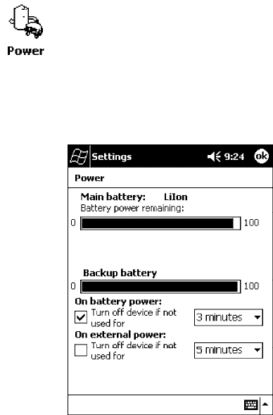
IntroductionChapter —1
2 700 Series Color Mobile Computer User’s Manual
About the 700 Series Color Mobile Computer
Audio System
Speaker
A speaker capable of variable volume levels is located on the back of the
computer. This speaker has a transducer volume of 85 dB min at 10 CM
and a frequency range of 1-8 KHz.
Internal Microphone
The internal microphone is located on the bottom of the unit to the left of
the hirose connector.
External Headset Jack
The external headset jack connects a mono headset to your mobile com-
puter for use in noisy environments. The jack is a 2.5 mm, three-conduc-
tor jack, with autosensing of the headset jack insertion which disables the
internal speaker and microphone. The external headset jack is located on
the bottom of the mobile computer to the right of the hirose connector.
Battery
The 700 Series Computer comes equipped with a nominal 14.4
Watt-hour, 7.2V (two 2000 mAh cells), replaceable Lithium-Ion (LiIon)
battery. To view the status of this battery from the 700 Series Computer,
tap Start →Settings →the System tab →the Power icon to view the
current status of both the main battery and the backup battery. Tap ok to
exit this information.
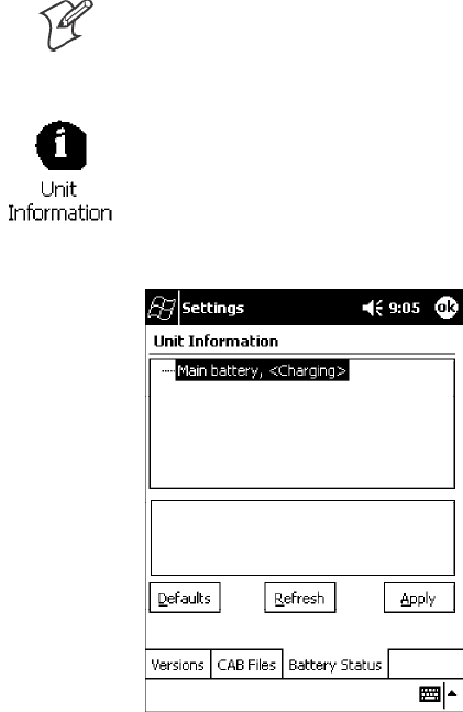
Introduction—Chapter 1
3700 Series Color Mobile Computer User’s Manual
Note: The Unit Information control panel applet is only available in the
700 Series Computer if Intermec Content is enabled, the Plus region is
enabled and installed, and a laser scanner is installed.
You can also view the battery status for the 700 Series Computer by
accessing the Unit Information control panel applet. Tap the Unit
Information icon, then tap the Battery Status tab to view the current
status. Tap ok to exit this information.
Low Battery Shutdown
If your computer shuts down because of low battery conditions, your com-
puter will not operate. This is done to ensure that data is protected. Al-
though the battery will protect the data against loss for several hours, you
should connect your computer to a power source when you first detect a
low battery condition.
Your computer contains an internal super capacitor, a temporary power
storage device, that protects data for up to ten minutes. This is to give you
time to replace the main battery pack before that data is lost. Be sure to put
the computer in a suspend mode before doing so.
The battery power fail level is set so that after the system shuts down in a
low battery condition, there is still sufficient charge to allow the unit to
remain configured, keep proper time, and maintain DRAM (Dynamic
Random Access Memory) for at least 72 hours at room temperature if the
main battery remains in the mobile computer. The configuration and time
are lost if:
SThe battery discharges beyond this level.
SThe battery is removed when the computer is not in suspend mode.
SA cold reset is performed on the computer.
IntroductionChapter —1
4 700 Series Color Mobile Computer User’s Manual
System Status Maintained
System status is maintained in “suspend” when the main battery is re-
moved:
S10 minutes for 64 MB low-power chips
S5 minutes for 128 MB low-power chips
CAB Files Within 700C Software Tools CD
If you leave the default destination while you install the “\700 Color
Mgmt Tools” directory onto your desktop PC, then “C:\Intermec\Inter-
mec 700 Color Mgmt Tools\Cab Files” will be the default directory. There
are folders within the “\Cab Files” directory that contain demos and pro-
gram files. See the 700 Series Color Software Tools CD User’ s Manual for
more information about these files.
Modem Support
Modem PC Cards are not supported by the 700 Series Computer. Howev-
er, modem options do include the following:
SSwitchable dock that includes a built-in modem and a serial port be-
tween which an application can switch.
SMini-Landline Modem that can be tethered to the port on the bottom
of the 700 Series Computer.
SOther external modems that may be connected to the bottom of the
700 Series Computer or to the dock.
Network Support
Radio CompactFlash Cards cannot be installed by a user. The 700 Series
Computer must be serviced to install or replace radios. See Chapter 4,
“Network Support” for more information.
S802.11b radio
SIntegrated GSM/GPRS radio
SCDPM/1xRTT radio
SWireless printing equipped with a Bluetooth qualified module by Socket
Communications
Introduction—Chapter 1
5700 Series Color Mobile Computer User’s Manual
Removeable Card Support
To access either the CompactFlash (CF) or SecureDigital (SD) card slot,
locate the access door at the top of the 700 Series Computer, remove its
two screws, then remove the door.
CompactFlash Cards
Support is limited to one CompactFlash (CF) Storage Card in the 700 Se-
ries Computer, either for storage or for the 802.11b radio.
SecureDigital Cards
Support is limited to one SecureDigital (SD) Storage Card in the 700 Se-
ries Computer for storage.
MultiMediaCards
MultiMediaCards (MMCs) are not supported in the 700 Series Comput-
ers because current technology shows that SD cards will quickly surpass
MMC cards in storage capacity.
Software Build Version
To check to see if your 700 Series Computer has the latest build, select
Start →Internet Explorer →the Intermec logo.
The latest software build version is displayed beneath the Patent Informa-
tion title. This information will be useful should you need customer assis-
tance.
Note: The Unit Information control panel applet is only available in the
700 Series Computer if Intermec Content is enabled, the Plus region is
enabled and installed, and a laser scanner is installed.
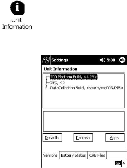
IntroductionChapter —1
6 700 Series Color Mobile Computer User’s Manual
You can also view the latest software build version on your 700 Series
Computer by accessing the Unit Information control panel applet. Select
Start →Settings →the System tab →the Unit Information icon →the
Versions tab to view the current build version on your 700 Series
Computer.
What’s New
The newest functionality is available in software build versions 1.30 or
greater. The following changes have occurred since the last release of this
manual:
SApplied new publications standards to this manual.
SAdapted instructions using Ethernet connections to fit Intermec require-
ments in Chapter 2, “Pocket PC 2002.”
SMoved “Updating System Software” and “EFlash” information to the Re-
covery CD User’ s Manual from Chapter 3, “Installing Applications.”
SRemoved several 802.11 APIs not related to the 700 Series Color Com-
puter from Chapter 4, “Network Support.”
SAdded the Siemens MC45 radio module to Chapter 4, “Network Sup-
port.”
SAdded tethered scanner information to Chapter 6, “Scanner Support.”
SAdded CAB extraction information and FTP Server parameters to
Chapter 7, “Programming.”
SAdded imager option information via the Data Collection control panel
applet to Appendix A, “Control Panel Applets.”Note that this is for 700
Series Computers using an imager.

7700 Series Color Mobile Computer User’s Manual
Pocket PC 2002
2
This chapter introduces the Pocket PC 2002 operating system from
Microsoft Corporation.

Pocket PC 2002Chapter —2
8 700 Series Color Mobile Computer User’s Manual
Introduction
Congratulations on purchasing a Pocket PC. Due to the size and capabili-
ties of this 700 Series Color Mobile Computer, you can keep your most
important business and personal information up-to-date and close at hand.
Microsoft ActiveSync increases the power of your 700 Series Computer by
allowing you to synchronize the information on your desktop or laptop
computer with your 700 Series Computer. Picture yourself in the follow-
ing situations:
SA Calendar reminder alerts you that it is time to catch the bus. You grab
your 700 Color Pocket PC Mobile Computer and catch the bus just in
time. Because ActiveSync keeps the information on your 700 Series
Computer up-to-date, you leisurely review your task list, make notes
about the new books and CDs you want to buy, and read and respond
to e-mail messages. When you get back to the office, ActiveSync trans-
fers any task changes you made, your notes, and your e-mail message
responses to your desktop computer. For more information on Active-
Sync, see “Microsoft ActiveSync” on page 29.
SWhile walking with a colleague, your 700 Color Pocket PC Mobile
Computer rings. You look at the caller ID and see it is your manager
who is calling. She asks if you two are free this afternoon for an emer-
gency meeting. While your colleague fumbles through his paper orga-
nizer, you press a button on your 700 Series Computer and instantly see
a list of today’ s appointments and meetings. You are quickly able to tell
your manager your available times, and make a note of the new meeting
while on the call. You hang up, send an e-mail with a schedule request
for the three of you at the desired location. For more information on
scheduling appointments and meetings, see “Microsoft Pocket Outlook”
on page 31.
SYou are meeting your friends tonight for dinner and a movie. You
download the latest movie information from the Internet to your desk-
top computer and then synchronize it with your 700 Series Computer.
At dinner, you pull out your 700 Color Pocket PC Mobile Computer
and review your movie options with your friends. For more information
on downloading Web pages to your 700 Series Computer, see “Pocket
Internet Explorer” on page 62.
Premium versus Professional Editions
Your 700 Series Computer will have either the Premium Edition or the
Professional Edition of Pocket PC 2002. Do the following to determine
which edition of Pocket PC 2002 is on your unit.
1Select Start →Internet Explorer →the Intermec logo.
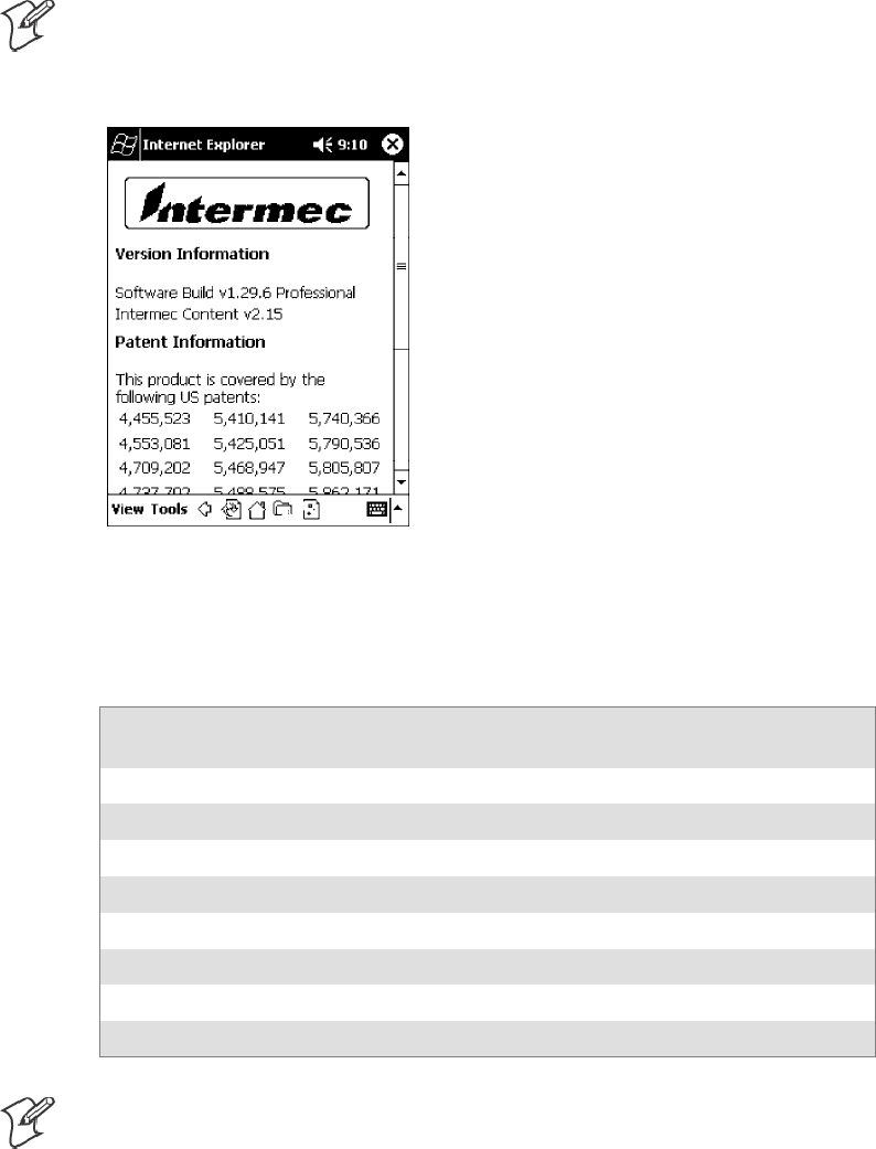
Pocket PC 2002—Chapter 2
9700 Series Color Mobile Computer User’s Manual
2Note the “Software Build” information displayed beneath the Version
Information title.
Note: If you have an older software build, your unit may say either
“PREM” (which indicates the Premium Edition) or “PRO” (which indicates
the Professional Edition).
3Tap t he Close icon in the top right corner to exit the Internet Explorer.
Below is a list of components for each edition of Pocket PC 2002:
Component
Premium
Edition
Professional
Edition
Microsoft ActiveSync Client (page 29) XX
Microsoft Pocket Outlook (page 31) X X
Pocket Word (page 47) XX
Pocket Excel (page 52) X X
MSN Messenger (page 53) X
Windows Media Player for Pocket PC (page 57) XRAM
Microsoft Reader (page 58) XRAM
Pocket Internet Explorer (page 62) X X
Note: Components marked with “RAM” are provided on a Companion
CD for download into RAM rather than burned into Flash ROM.

Pocket PC 2002Chapter —2
10 700 Series Color Mobile Computer User’s Manual
Where to Find Information
This chapter describes your 700 Series Computer hardware, provides an
overview of the programs on your 700 Series Computer, and explains how
to connect your 700 Series Computer to a desktop computer, a network,
or the Internet. For instructions on setting up your 700 Series Computer
and installing ActiveSync, see the Quick Start Card. The following is a
guide to more information to assist you use your 700 Series Computer.
For information on: See this source:
Programs on your mobile computer. This chapter and mobile computer Help. To view Help,
tap Start →Help.
Additional programs that can be installed on the mobile
computer.
The Pocket PC Companion CD.
Connecting to and synchronizing with a desktop com-
puter.
The Quick Start Card or AutoSync Help on your desktop
computer. To view Help, click Help →Microsoft Acti-
veSync Help.
Last-minute updates and detailed technical information. The Read Me files, located in the Microsoft ActiveSync
folder on the desktop computer and on the Pocket PC
Companion CD.
Up-to-date information on your Pocket PC. http://www.microsoft.com/mobile/pocketpc
Pocket PC and many of the technologies supported by the 700 Series
Computer are not from Intermec Technologies. Many of the utilities and
features on a Pocket PC device come directly from Microsoft without any
modification from Intermec Technologies. There may be certain Micro-
soft-specific issues that Intermec Technologies would not be able to sup-
port, so you will have to contact Microsoft Corporation. Use these URLs
to determine your Microsoft support options:
Shttp://msdn.microsoft.com/support/
Shttp://support.microsoft.com/
Snews://news.microsoft.com (a free support option)
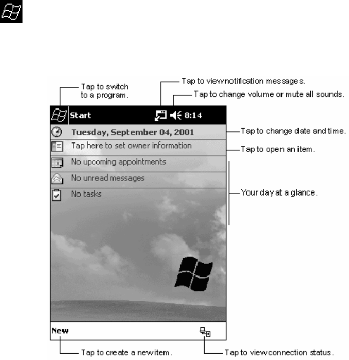
Pocket PC 2002—Chapter 2
11700 Series Color Mobile Computer User’s Manual
Basic Skills
Learning to use your 700 Series Computer is easy. This describes the basic
concepts of using and customizing your 700 Series Computer.
Buttons and Stylus
Your 700 Series Computer has hardware buttons that control actions and
scroll functions, and a stylus for selecting items and entering information.
On the 700 Series Computer, the stylus replaces the mouse.
STap:
Touch the screen once with the stylus to open items and select options.
SDrag:
Hold the stylus on the screen and drag across the screen to select text
and images. Drag in a list to select multiple items.
STap and hold:
Tap and hold the stylus on an item to see a list of actions available for
that item. On the pop-up menu that appears, tap the action to be per-
formed.
Today Screen
When you turn on your 700 Series Computer for the first time each day
(or after four hours of inactivity), you will see the Today screen. You can
also display it by tapping the Start flag (shown left) and then Today.On
the Today screen, you can see at a glance important information for the
day.

Pocket PC 2002Chapter —2
12 700 Series Color Mobile Computer User’s Manual
Following are some of the status icons you may see:
Status Icon Meaning:
Turns all sounds on and off.
Backup battery is low.
Main batteries are charging.
Main batteries are low.
Main batteries are very low.
Main batteries are full.
Connection is active.
Synchronization is beginning or ending.
Synchronization is occurring.
Notification or one or more instant messages received.
Notification of one or more e-mail messages received.
If more notification icons need to be displayed than there is
room to display them, the Notification icon (shown left) will
display. Tap the icon to view all notification icons.

Pocket PC 2002—Chapter 2
13700 Series Color Mobile Computer User’s Manual
Programs
You can switch from one program to another by selecting it from the Start
menu. (You can customize which programs you see on this menu. For
information, see “Adjusting Settings” on page 26.) To access some
programs, tap Start →Programs, and then the program name.
You can also switch to some programs by pressing a program button. Your
700 Series Computer has one or more program buttons located on the
front or side of the computer. The icons on the buttons identify the pro-
grams to which they switch.
Note: Some programs have abbreviated labels for check boxes and drop-
down menus. To see the full spelling of an abbreviated label, tap and hold
the stylus on the label. Drag the stylus off the label so that the command is
not carried out.
The following is a partial list of programs that are on your 700 Series
Computer. Look on the Pocket PC Companion CD for additional pro-
grams that you can install onto your 700 Series Computer.
ActiveSync
Synchronize information between your 700 Series Computer and desktop
computer.
Calendar
Keep track of your appointments and create meeting requests.
Contacts
Keep track of your friends and colleagues.
Inbox
Send and receive e-mail messages.
Pocket Internet Explorer
Browse Web and WAP (Wireless Application Protocol) sites, and download
new programs and files from the Internet.
Notes
Create handwritten or typed notes, drawings, and recordings.
Tasks
Keep track of your tasks.
Pocket Excel
Create new workbooks or view and edit Excel workbooks created on your
desktop computer.
MSN Messenger
Send and receive instant messages with your MSN Messenger contacts.
Pocket Word
Create new documents or view and edit Word documents created on your
desktop computer.
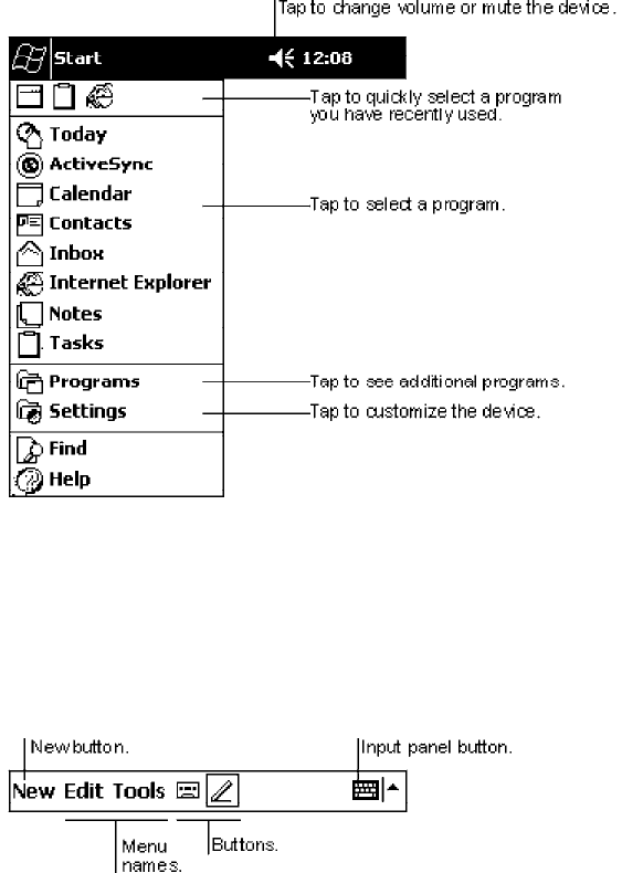
Pocket PC 2002Chapter —2
14 700 Series Color Mobile Computer User’s Manual
Navigation Bar and Command Bar
The navigation bar is located at the top of the screen. It displays the active
program and current time, and allows you to switch to programs and close
screens.
Use the command bar at the bottom of the screen to perform tasks in pro-
grams. The command bar includes menu names, buttons, and the Input
Panel button. To create a new item in the current program, tap New.To
see the name of a button, tap and hold the stylus on the button. Drag the
stylus off the button so that the command is not carried out.
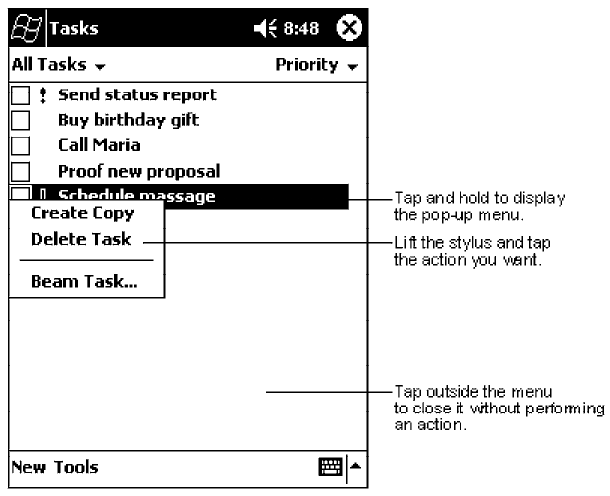
Pocket PC 2002—Chapter 2
15700 Series Color Mobile Computer User’s Manual
Pop-up Menus
With pop-up menus, you can quickly choose an action for an item. For
example, you can use the pop-up menu in the contact list to quickly delete
a contact, make a copy of a contact, or send an e-mail message to a con-
tact. The actions in the pop-up menus vary from program to program. To
access a pop-up menu, tap and hold the stylus on the item name that you
want to perform the action on. When the menu appears, lift the stylus,
and tap the action you want to perform. Or tap anywhere outside the
menu to close the menu without performing an action.
Notifications
Your 700 Series Computer reminds you in a variety of ways when you
have something to do. For example, if you have set up an appointment in
Calendar, a task with a due date in Tasks, or an alarm in Clock, you will be
notified in any of the following ways:
SA message box appears on the screen.
SA sound, which you can specify, is played.
SA light flashes on your 700 Series Computer.
SA vibrator resonates from the 700 Series Computer.
To choose reminder types and sounds for your 700 Series Computer, tap
Start →Settings →the Personal tab →Sounds & Notifications. The
options you choose here apply throughout the 700 Series Computer.
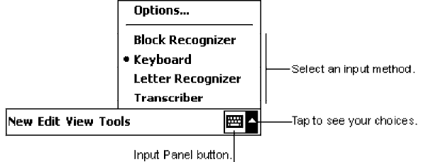
Pocket PC 2002Chapter —2
16 700 Series Color Mobile Computer User’s Manual
Enter Information on Your 700 Series Computer
You have several options for entering new information:
SUse the input panel to enter typed text, either by using the soft key-
board or other input method.
SWrite directly on the screen.
SDraw pictures on the screen.
SSpeak into your 700 Series Computer microphone to record a message.
SUse Microsoft ActiveSync to synchronize or copy information from
your desktop computer to your 700 Series Computer. For more infor-
mation on ActiveSync, see ActiveSync Help on your desktop computer.
Use the input panel to enter information in any program on your 700
Series Computer. You can either type using the soft keyboard or write
using Block Recognizer,Letter Recognizer,orTranscriber. In either case,
the characters appear as typed text on the screen.
To show or hide the input panel, tap the Input Panel button. Tap the
arrow next to the Input Panel button to see your choices.
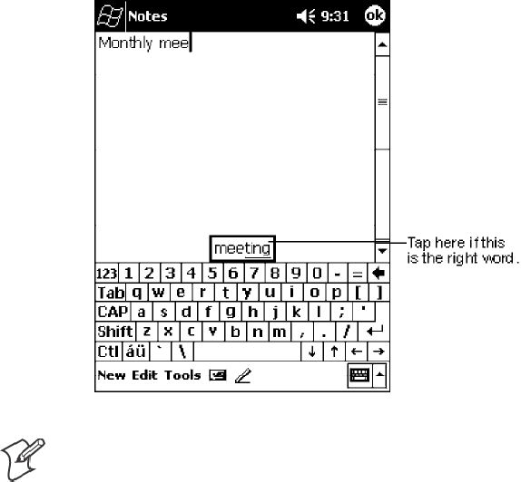
Pocket PC 2002—Chapter 2
17700 Series Color Mobile Computer User’s Manual
When you use the input panel, your 700 Series Computer anticipates the
word you are typing or writing and displays it above the input panel.
When you tap the displayed word, it is inserted into your text at the
insertion point. The more you use your 700 Series Computer, the more
words it learns to anticipate.
Note: To change word suggestion options, such as the number of words
suggested at one time, tap Start →Settings →the Personal tab →Input
→the Word Completion tab.
Typing With the Soft Keyboard
1Tap the arrow next to the Input Panel button, and then Keyboard.
2On the soft keyboard that is displayed, tap the keys with your stylus.
Using Block Recognizer
With Block Recognizer, you can input character strokes using the stylus
that are similar to those used on other 700 Series Computers.
1Tap the arrow next to the Input Panel button, then Block Recognizer.
2Write a letter in the box.
When you write a letter, it is converted to typed text that appears on the
screen. For specific instructions on using Block Recognizer, with Block
Recognizer open, tap the question mark next to the writing area.
Pocket PC 2002Chapter —2
18 700 Series Color Mobile Computer User’s Manual
Using Letter Recognizer
With Letter Recognizer, you can write letters using the stylus just as you
would on paper.
1Tap the arrow next to the Input Panel button, then Letter Recognizer.
2Write a letter in the box.
When you write a letter, it is converted to typed text that appears on the
screen. For specific instructions on using Letter Recognizer, with Letter
Recognizer open, tap the question mark next to the writing area.
Using Transcriber
With Transcriber, you can write anywhere on the screen using the stylus
just as you would on paper. Unlike Letter Recognizer and Block Recogniz-
er, you can write a sentence or more of information. Then, pause and let
Transcriber change the written characters to typed characters.
1Tap the arrow next to the Input Panel button, and then Transcriber.
2Write anywhere on the screen.
For specific instructions on using Transcriber, with Transcriber open, tap
the question mark in the lower right hand corner of the screen.
Selecting Typed Text
If you want to edit or format typed text, you must select it first.
SDrag the stylus across the text you want to select.
You can cut, copy, and paste text by tapping and holding the selected
words and then tapping an editing command on the pop-up menu, or by
tapping the command on the Edit menu.

Pocket PC 2002—Chapter 2
19700 Series Color Mobile Computer User’s Manual
Writing on the Screen
In any program that accepts writing, such as the Notes program, and in
the Notes tab in Calendar, Contacts, and Tasks, you can use your stylus to
write directly on the screen. Write the way you do on paper. You can edit
and format what you have written and convert the information to text at a
later time.
STap t he Pen button to switch to writing mode. This action displays lines
on the screen to help you write.
Note: Some programs that accept writing may not have the Pen button.
See the documentation for that program to find out how to switch to writ-
ing mode.
Selecting the Writing
If you want to edit or format writing, you must select it first.
1Tap and hold the stylus next to the text you want to select until the in-
sertion point appears.
2Without lifting, drag the stylus across the text you want to select.
If you accidentally write on the screen, tap Tools →Undo and try again.
You can also select text by tapping the Pen button to deselect it and then
dragging the stylus across the screen.
You can cut, copy, and paste written text in the same way you work with
typed text: tap and hold the selected words and then tap an editing com-
mand on the pop-up menu, or tap the command on the Edit menu.
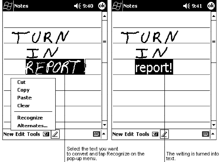
Pocket PC 2002Chapter —2
20 700 Series Color Mobile Computer User’s Manual
Converting Writing to Text
STap Tools →Recognize.
If you want to convert only certain words, select them before tapping Rec-
ognize on the Tools menu (or tap and hold the selected words and then tap
Recognize on the pop-up menu). If a word is not recognized, it is left as
writing.
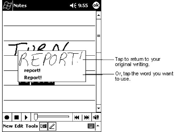
Pocket PC 2002—Chapter 2
21700 Series Color Mobile Computer User’s Manual
If the conversion is incorrect, you can select different words from a list of
alternates or return to the original writing. To do so, tap and hold the in-
correct word (tap one word at a time). On the pop-up menu, tap Alterna-
tes. A menu with a list of alternate words appears. Tap the word you want
to use, or tap the writing at the top of the menu to return to the original
writing.
Tips for getting good recognition:
SWrite neatly.
SWrite on the lines and draw descenders below the line. Write the cross
of the “t” and apostrophes below the top line so that they are not con-
fused with the word above. Write periods and commas above the line.
SFor better recognition, try increasing the zoom level to 300% using the
Tools menu.
SWrite the letters of a word closely and leave big gaps between words so
that the 700 Series Computer can easily tell where words begin and end.
SHyphenated words, foreign words that use special characters such as ac-
cents, and some punctuation cannot be converted.
SIf you add writing to a word to change it (such as changing a “3” to an
“8”) after you attempt to recognize the word, the writing you add will
not be included if you attempt to recognize the writing again.
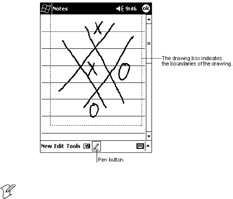
Pocket PC 2002Chapter —2
22 700 Series Color Mobile Computer User’s Manual
Drawing on the Screen
You can draw on the screen in the same way that you write on the screen.
The difference between writing and drawing on the screen is how you se-
lect items and how they can be edited. For example, selected drawings can
be resized, while writing cannot.
Creating a Drawing
SCross three ruled lines on your first stroke. A drawing box appears. Sub-
sequent strokes in or touching the drawing box become part of the dra-
wing. Drawings that do not cross three ruled lines will be treated as
writing.
Note: You may want to change the zoom level so that you can more easily
work on or view your drawing. Tap Tools and then a zoom level.
Selecting a Drawing
If you want to edit or format a drawing, you must select it first.
STap and hold the stylus on the drawing until the selection handle ap-
pears. To select multiple drawings, deselect the Pen button and then
drag to select the drawings you want.
You can cut, copy, and paste selected drawings by tapping and holding the
selected drawing and then tapping an editing command on the pop-up
menu, or by tapping the command on the Edit menu. To resize a drawing,
make sure the Pen button is not selected, and drag a selection handle.
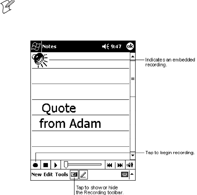
Pocket PC 2002—Chapter 2
23700 Series Color Mobile Computer User’s Manual
Recording a Message
In any program where you can write or draw on the screen, you can also
quickly capture thoughts, reminders, and phone numbers by recording a
message. In Calendar, Tasks, and Contacts, you can include a recording in
the Notes tab. In the Notes program, you can create a stand-alone record-
ing or include a recording in a written note. If you want to include the re-
cording in a note, open the note first. In the Inbox program, you can add a
recording to an e-mail message.
Creating a Recording
1Hold your computer’ s microphone near your mouth or source of
sound.
2Press and hold the Record hardware button on your 700 Series Com-
puter until you hear a beep.
3While holding down the Record button, make your recording.
4To stop recording, release the Record button. Two beeps will sound.
The new recording appears in the note list or as an embedded icon.
Note: You can also make a recording by tapping the Record button on the
Recording toolbar.
To play a recording, tap it in the list or tap its icon in the note.
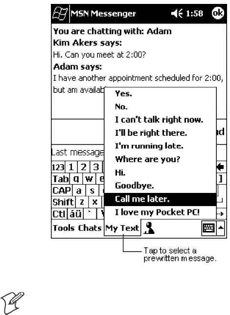
Pocket PC 2002Chapter —2
24 700 Series Color Mobile Computer User’s Manual
Using My Text
When using Inbox or MSN Messenger, use My Text to quickly insert pre-
set or frequently used messages into the text entry area. To insert a mes-
sage, tap My Text and tap a message.
Note: You can add text after inserting a My Text message before sending
it.
To edit a My Text message, in the Tools menu, tap Edit →My Text Mes-
sages. Select the message you wish to edit and make desired changes.
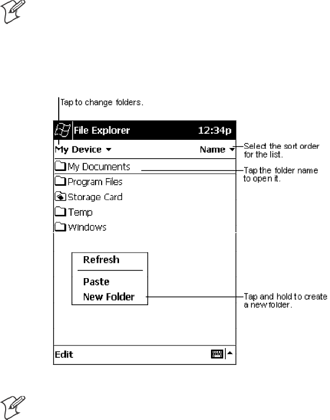
Pocket PC 2002—Chapter 2
25700 Series Color Mobile Computer User’s Manual
Finding and Organizing Information
The Find feature on your 700 Series Computer helps you quickly locate
information.
Tap Start →Find. Enter the text you want to find, select a data type, and
then tap Go to initiate the search.
Note: To quickly find information that is taking up storage space on your
700 Series Computer, select Larger than 64 KB in Type.
You can also use the File Explorer to find files on your 700 Series Comput-
er and to organize these files into folders. Tap Start →Programs →File
Explorer.
Note: You can move files in File Explorer by tapping and holding the item
you want to move, and then tapping Cut or Copy and Paste on the pop-
up menu.
Pocket PC 2002Chapter —2
26 700 Series Color Mobile Computer User’s Manual
Customizing Your 700 Series Computer
You can customize your 700 Series Computer by adjusting settings and
installing additional software.
Adjusting Settings
You can adjust settings to suit the way you work. To see available options,
tap Start →Settings →either the Personal tab or the System tab located at
the bottom of the screen. You might want to adjust the following:
SClock:
To change the time or to set alarms.
SMenus:
To customize what appears on the Start menu, and to enable a pop-up
menu from the New button.
SOwner Information:
To enter your contact information.
SPassword:
To limit access to your 700 Series Computer.
SPower:
To maximize battery life.
SToday:
To customize the look and information displayed on the Today screen.
Adding or Removing Programs
Programs added to your 700 Series Computer at the factory are stored in
ROM (Read Only Memory). You cannot remove this software, and you
will never accidentally lose ROM contents. ROM programs can be up-
dated using special installation programs with a *.XIP extension. All other
programs and data files added to your 700 Series Computer after factory
installation are stored in RAM (Random Access Memory).
You can install any program created for your 700 Series Computer, as long
as your 700 Series Computer has enough memory. The most popular place
to find software for your 700 Series Computer is on the Pocket PC Web
site (http://www.microsoft.com/mobile/pocketpc).
Adding Programs Using ActiveSync
You will need to install the appropriate software for your 700 Series Com-
puter on your desktop computer before installing it on your 700 Series
Computer.
1Determine your 700 Series Computer and processor type so that you
know which version of the software to install. Tap Start →Settings →
the System tab →About →the Version tab, then make a note of the
information in Processor.
2Download the program to your desktop computer (or insert the CD or
disk that contains the program into your desktop computer). You may
see a single *.XIP, *.EXE, or *.ZIP file, a SETUP.EXE file, or several
versions of files for different 700 Series Computer types and processors.
Be sure to select the program designed for the Pocket PC and your 700
Series Computer processor type.
Pocket PC 2002—Chapter 2
27700 Series Color Mobile Computer User’s Manual
3Read any installation instructions, Read Me files, or documentation that
comes with the program. Many programs provide special installation
instructions.
4Connect your 700 Series Computer and desktop computer.
5Double-click the *.EXE file.
SIf the file is an installer, the installation wizard will begin. Follow the
directions on the screen. Once the software has been installed on your
desktop computer, the installer will automatically transfer the soft-
ware to your 700 Series Computer.
SIf the file is not an installer, you will see an error message stating that
the program is valid but it is designed for a different type of comput-
er. You will need to move this file to your 700 Series Computer. If
you cannot find any installation instructions for the program in the
Read Me file or documentation, use ActiveSync Explore to copy the
program file to the Program Files folder on your 700 Series Comput-
er. For more information on copying files using ActiveSync, see Acti-
veSync Help.
Once installation is complete, tap Start →Programs, and then the pro-
gram icon to switch to it.
Adding a Program Directly from the Internet
1Determine your 700 Series Computer and processor type so that you
know which version of the software to install. Tap Start →Settings →
the System tab →About →the Version tab, then make a note of the
information in Processor.
2Download the program to your 700 Series Computer straight from the
Internet using Pocket Internet Explorer. You may see a single *.XIP,
*.EXE, or *.ZIP file, a SETUP.EXE file, or several versions of files for
different 700 Series Computer types and processors. Be sure to select the
program designed for the Pocket PC and your 700 Series Computer
processor type.
3Read any installation instructions, Read Me files, or documentation that
comes with the program. Many programs provide installation instruc-
tions.
4Tap the file, such as a *.XIP or *.EXE file. The installation wizard will
begin. Follow the directions on the screen.
Pocket PC 2002Chapter —2
28 700 Series Color Mobile Computer User’s Manual
Adding a Program to the Start Menu
Tap Start →Settings →Menus →the Start Menu tab, and then the check
box for the program. If you do not see the program listed, you can either
use File Explorer on the 700 Series Computer to move the program to the
Start Menu folder, or use ActiveSync on the desktop computer to create a
shortcut to the program and place the shortcut in the Start Menu folder.
SUsing File Explorer on the 700 Series Computer:
Tap Start →Programs →File Explorer, and locate the program (tap the
folder list, labeled My Documents by default, and then My Device to
see a list of all folders on the 700 Series Computer). Tap and hold the
program and tap Cut on the pop-up menu. Open the Start Menu fold-
er located in the Windows folder, tap and hold a blank area of the win-
dow, and tap Paste on the pop-up menu. The program will now appear
on the Start menu. For more information on using File Explorer, see
“Finding and Organizing Information” on page 25.
SUsing ActiveSync on the desktop computer:
Use the Explorer in ActiveSync to explore your 700 Series Computer
files and locate the program. Right-click the program, and then click
Create Shortcut. Move the shortcut to the Start Menu folder in the
Windows folder. The shortcut now appears on the Start menu. For
more information, see ActiveSync Help.
Removing Programs
STap Start →Settings →the System tab →Remove Programs.
If the program does not appear in the list of installed programs, use File
Explorer on your 700 Series Computer to locate the program, tap and hold
the program, and then tap Delete on the pop-up menu.

Pocket PC 2002—Chapter 2
29700 Series Color Mobile Computer User’s Manual
Microsoft ActiveSync
Visit the following Microsoft Web site for the latest in updates, technical
information, and samples:
Shttp://www.microsoft.com/mobile/pocketpc/downloads/activesync.asp
Using Microsoft ActiveSync, you can synchronize the information on your
desktop computer with the information on your 700 Series Computer.
Synchronization compares the data on your 700 Series Computer with
your desktop computer and updates both computers with the most recent
information. For example:
SKeep Pocket Outlook data up-to-date by synchronizing your 700 Series
Computer with Microsoft Outlook data on your desktop computer.
SSynchronize Microsoft Word and Microsoft Excel files between your
700 Series Computer and desktop computer. Your files are automatically
converted to the correct format
Note: By default, ActiveSync does not automatically synchronize all types
of information. Use ActiveSync options to turn synchronization on and off
for specific information types.
With ActiveSync, you can also:
SBack up and restore your 700 Series Computer data.
SCopy (rather than synchronize) files between your 700 Series Computer
and desktop computer.
SControl when synchronization occurs by selecting a synchronization
mode. For example, you can synchronize continually while connected to
your desktop computer or only when you choose the synchronize com-
mand.
SSelect which information types are synchronized and control how much
data is synchronized. For example, you can choose how many weeks of
past appointments you want synchronized.
Before you begin synchronization, install ActiveSync on your desktop
computer from the Pocket PC Companion CD. For more information on
installing ActiveSync, see your Quick Start card. ActiveSync is already
installed on your 700 Series Computer.
After installation is complete, the ActiveSync Setup Wizard helps you con-
nect your 700 Series Computer to your desktop computer, set up a part-
nership so you can synchronize information between your 700 Series
Computer and your desktop computer, and customize your synchroniza-
tion settings. Your first synchronization process will automatically begin
when you finish using the wizard.
After your first synchronization, take a look at Calendar, Contacts, and
Tasks on your 700 Series Computer. You will notice that information you
have stored in Microsoft Outlook on your desktop computer has been
copied to your 700 Series Computer, and you did not have to type a word.
Disconnect your 700 Series Computer from your computer and you are
ready to go!
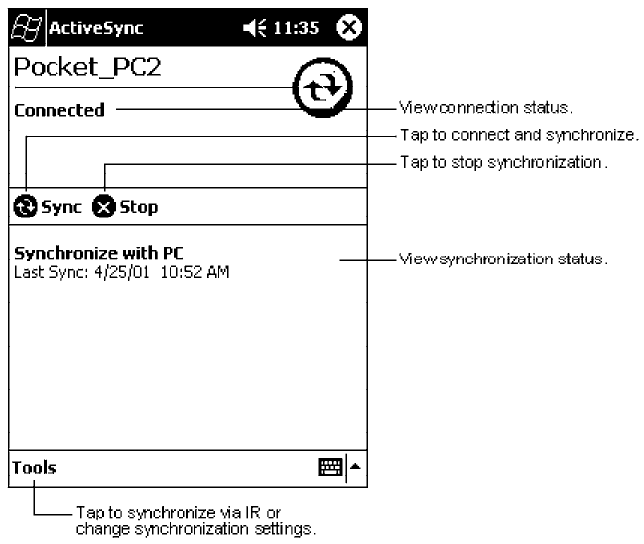
Pocket PC 2002Chapter —2
30 700 Series Color Mobile Computer User’s Manual
Once you have set up ActiveSync and completed the first synchronization
process, you can initiate synchronization from your 700 Series Computer.
To switch to ActiveSync on your 700 Series Computer, tap Start →
ActiveSync. Note that if you have a wireless LAN card, you can
synchronize remotely from your 700 Series Computer.
For information about using ActiveSync on your desktop computer, start
ActiveSync on your desktop computer, and then see ActiveSync Help.
For more information about ActiveSync on your 700 Series Computer,
switch to ActiveSync, then tap Start →Help.
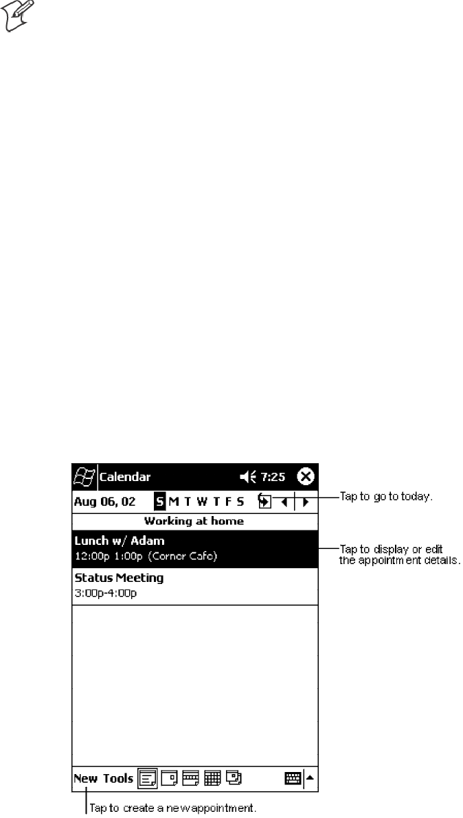
Pocket PC 2002—Chapter 2
31700 Series Color Mobile Computer User’s Manual
Microsoft Pocket Outlook
Note: The Professional Edition of Microsoft Pocket Outlook does not in-
clude a spell checker.
Microsoft Pocket Outlook includes Calendar, Contacts, Tasks, Inbox, and
Notes. You can use these programs individually or together. For example,
e-mail addresses stored in Contacts can be used to address e-mail messages
in Inbox.
Using ActiveSync, you can synchronize information in Microsoft Outlook
or Microsoft Exchange on your desktop computer with your 700 Series
Computer. You can also synchronize this information directly with a
Microsoft Exchange server. Each time you synchronize, ActiveSync
compares the changes you made on your 700 Series Computer and desk-
top computer or server and updates both computers with the latest in-
formation. For information on using ActiveSync, see ActiveSync Help on
the desktop computer.
You can switch to any of these programs by tapping them on the Start
menu.
Calendar: Scheduling Appointments and Meetings
Use Calendar to schedule appointments, including meetings and other
events. You can check your appointments in one of several views (Agenda,
Day, Week, Month, and Year) and easily switch views by using the View
menu.
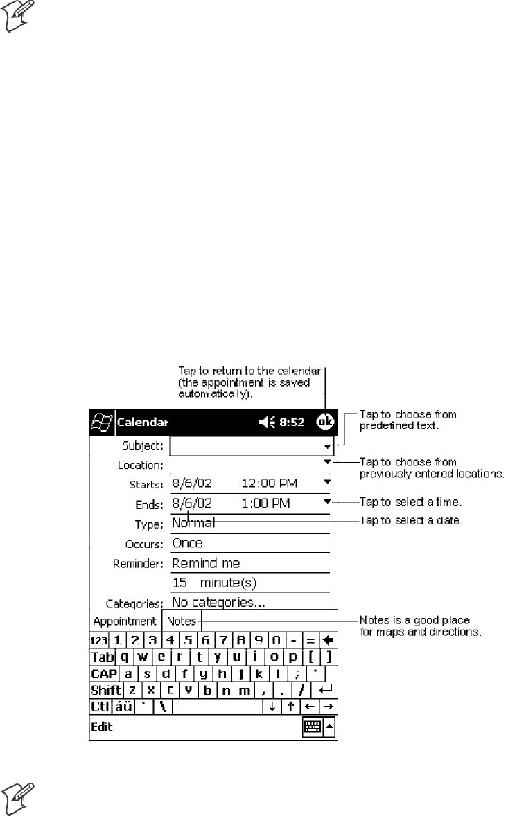
Pocket PC 2002Chapter —2
32 700 Series Color Mobile Computer User’s Manual
Note: You can customize the Calendar display, such as changing the first
day of the week, by tapping Options on the Tools menu.
Creating an Appointment
1If you are in Day or Week view, tap the desired date and time for the
appointment.
2Tap New.
3Using the input panel, enter a description and a location. Tap first to
select the field.
4If needed, tap the date and time to change them.
5Enter other desired information. You will need to hide the input panel
to see all available fields.
6To add notes, tap the Notes tab. You can enter text, draw, or create a
recording. For more information on creating notes, see “Notes: Capturing
Thoughts and Ideas” on page 40.
7When finished, tap OK to return to the calendar.
Note:IfyouselectRemind me in an appointment, your 700 Series Com-
puter will remind you according to the options set in Start →Settings →
the Personal tab →Sounds & Reminders.
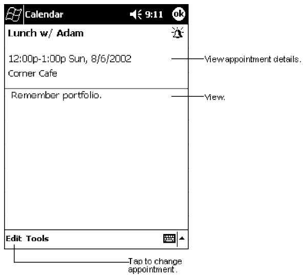
Pocket PC 2002—Chapter 2
33700 Series Color Mobile Computer User’s Manual
Using the Summary Screen
When you tap an appointment in Calendar, a summary screen is displayed.
To change the appointment, tap Edit.
Creating Meeting Requests
You can use Calendar to set up meetings with users of Outlook or Pocket
Outlook. The meeting request will be created automatically and sent either
when you synchronize Inbox or when you connect to your e-mail server.
Indicate how you want meeting requests sent by tapping Tools →
Options. If you send and receive e-mail messages through ActiveSync,
select ActiveSync.
Scheduling a Meeting
1Create an appointment.
2In the appointment details, hide the input panel, and then tap
Attendees.
3From the list of e-mail addresses you have entered in Contacts, select the
meeting attendees.
The meeting notice is created automatically and placed in the Outbox
folder.
For more information on sending and receiving meeting requests, see Cal-
endar Help and Inbox Help on the 700 Series Computer.
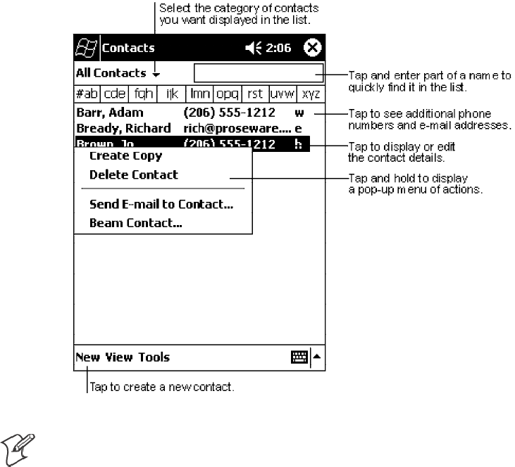
Pocket PC 2002Chapter —2
34 700 Series Color Mobile Computer User’s Manual
Contacts: Tracking Friends and Colleagues
Contacts maintains a list of your friends and colleagues so that you can
easily find the information you are looking for, whether you are at home
or on the road. Using the 700 Series Computer infrared (IR) port, you can
quickly share Contacts information with other 700 Series Computer users.
Note: To change the way information is displayed in the list, tap Tools →
Options.
Creating a Contact
1Tap New.
2Using the input panel, enter a name and other contact information. You
will need to scroll down to see all available fields.
3To assign the contact to a category, scroll to and tap Categories and se-
lect a category from the list. In the contact list, you can display contacts
by category.
4To add notes, tap the Notes tab. You can enter text, draw, or create a
recording. For more information on creating notes, see “Notes: Capturing
Thoughts and Ideas” on page 40.
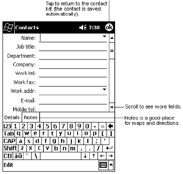
Pocket PC 2002—Chapter 2
35700 Series Color Mobile Computer User’s Manual
5When finished, tap OK to return to the contact list.
Finding a Contact
There are four ways to find a contact:
SIn the contact list, enter a contact name in the box under the navigation
bar. To show all contacts again, clear text from the box or tap the button
to the right of the box.
SIn the contact list, tap the category list (labeled All Contacts by default)
and select the type of contact that you want displayed. To show all con-
tacts again, select All Contacts. To view a contact not assigned to a cate-
gory, select None.
STo view the names of companies your contacts work for, in the contact
list, tap View →By Company. The number of contacts that work for
that company will be displayed to the right of the company name.
STap Start →Find, enter the contact name, select Contacts for the type,
and then tap Go.
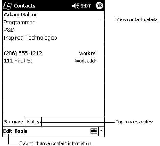
Pocket PC 2002Chapter —2
36 700 Series Color Mobile Computer User’s Manual
Using the Summary Screen
When you tap a contact in the contact list, a summary screen is displayed.
To change the contact information, tap Edit.
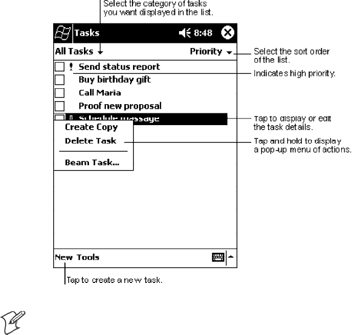
Pocket PC 2002—Chapter 2
37700 Series Color Mobile Computer User’s Manual
Tasks: Keeping a To Do List
Use Tasks to keep track of what you have to do.
Note: To change the way information is displayed in the list, tap Tools →
Options.
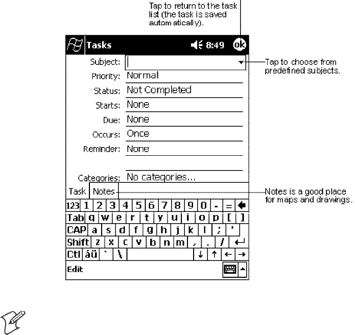
Pocket PC 2002Chapter —2
38 700 Series Color Mobile Computer User’s Manual
Creating a Task
1Tap New.
2Using the input panel, enter a description.
3You can enter a start date and due date or enter other information by
first tapping the field. If the input panel is open, you will need to hide it
to see all available fields.
4To assign the task to a category, tap Categories and select a category
from the list. In the task list, you can display tasks by category.
5To add notes, tap the Notes tab. You can enter text, draw, or create a
recording. For more information on creating notes, see “Notes: Capturing
Thoughts and Ideas” on page 40.
6When finished, tap OK to return to the task list.
Note: To quickly create a task with only a subject, tap Entry Bar on the
Tools menu. Then, tap Tap here to add a new task and enter your task
information.
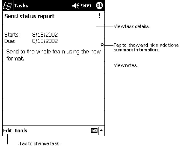
Pocket PC 2002—Chapter 2
39700 Series Color Mobile Computer User’s Manual
Using the Summary Screen
When you tap a task in the task list, a summary screen is displayed. To
change the task, tap Edit.
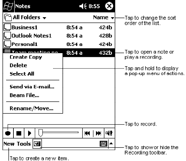
Pocket PC 2002Chapter —2
40 700 Series Color Mobile Computer User’s Manual
Notes: Capturing Thoughts and Ideas
Quickly capture thoughts, reminders, ideas, drawings, and phone numbers
with Notes. You can create a written note or a recording. You can also in-
clude a recording in a note. If a note is open when you create the record-
ing, it will be included in the note as an icon. If the note list is displayed, it
will be created as a stand-alone recording.
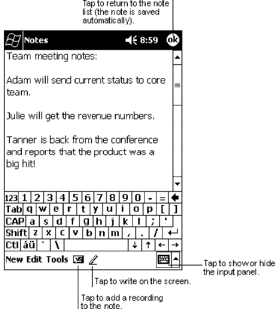
Pocket PC 2002—Chapter 2
41700 Series Color Mobile Computer User’s Manual
Creating a Note
1Tap New.
2Create your note by writing, drawing, typing, and recording. For more
information about using the input panel, writing and drawing on the
screen, and creating recordings, see “Basic Skills” on page 11.
Pocket PC 2002Chapter —2
42 700 Series Color Mobile Computer User’s Manual
Inbox: Sending and Receiving E-mail Messages
Use Inbox to send and receive e-mail messages in either of these ways:
SSynchronize e-mail messages with Microsoft Exchange or Microsoft
Outlook on your desktop computer.
SSend and receive e-mail messages by connecting directly to an e-mail
server through an Internet Service Provider (ISP) or a network.
Synchronizing E-mail Messages
E-mail messages can be synchronized as part of the general synchronization
process. You will need to enable Inbox synchronization in ActiveSync. For
information on enabling Inbox synchronization, see ActiveSync Help on the
desktop computer. During synchronization:
SMessages are copied from the mail folders of Exchange or Outlook on
your desktop computer to the ActiveSync folder in Inbox on your 700
Series Computer. By default, you will receive messages from the past
three days only, the first 100 lines of each message, and file attachments
of less than 100 KB in size.
SE-mail messages in the Outbox folder on your 700 Series Computer are
transferred to Exchange or Outlook, and then sent from those pro-
grams.
SE-mail messages in subfolders must be selected in ActiveSync on your
desktop computer in order to be transferred.
Connecting Directly to an E-mail Server
In addition to synchronizing e-mail messages with your desktop computer,
you can send and receive e-mail messages by connecting to an e-mail server
using a modem or network card connected to your 700 Series Computer.
You will need to set up a remote connection to a network or an ISP, and a
connection to your e-mail server. For more information, see “Getting Con-
nected” on page 67.
When you connect to the e-mail server, new messages are downloaded to
the 700 Series Computer Inbox folder, messages in the 700 Series Com-
puter Outbox folder are sent, and messages that have been deleted on the
e-mail server are removed from the 700 Series Computer Inbox folder.
Messages that you receive directly from an e-mail server are linked to your
e-mail server rather than your desktop computer. When you delete a mes-
sage on your 700 Series Computer, it is also deleted from the e-mail server
the next time you connect based on the settings selected in ActiveSync.
You can work online or offline. When working online, you read and re-
spond to messages while connected to the e-mail server. Messages are sent
as soon as you tap Send, which saves space on your 700 Series Computer.
When working offline, once you have downloaded new message headers or
partial messages, you can disconnect from the e-mail server and then de-
cide which messages to download completely. The next time you connect,
Inbox downloads the complete messages you have marked for retrieval and
sends the messages you have composed.
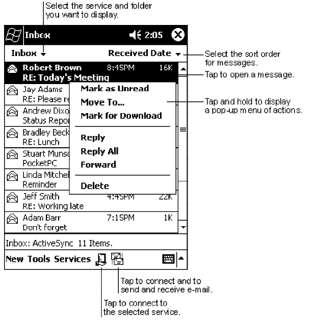
Pocket PC 2002—Chapter 2
43700 Series Color Mobile Computer User’s Manual
Using the Message List
Messages you receive are displayed in the message list. By default, the most
recently received messages are displayed first in the list.
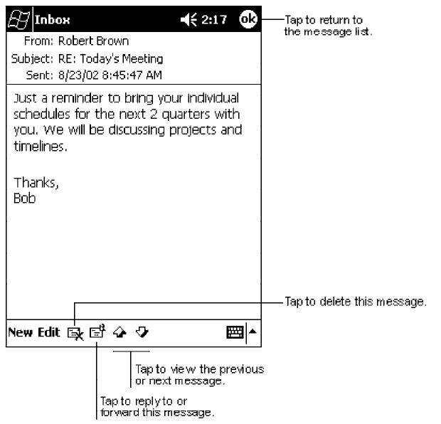
Pocket PC 2002Chapter —2
44 700 Series Color Mobile Computer User’s Manual
When you receive a message, tap it to open it. Unread messages are dis-
played in bold.
When you connect to your e-mail server or synchronize with your desktop
computer, by default, you will receive messages from the last five days
only, the first 100 lines of each new message, and file attachments of less
than 100 KB in size. The original messages remain on the e-mail server or
your desktop computer.
You can mark the messages that you want to retrieve in full during your
next synchronization or e-mail server connection. In the message list, tap
and hold the message you want to retrieve. On the pop-up menu, tap
Mark for Download. The icons in the Inbox message list give you visual
indications of message status.
You specify your downloading preferences when you set up the service or
select your synchronization options. You can change them at any time:
SChange options for Inbox synchronization using ActiveSync options.
For more information, see ActiveSync Help.
SChange options for direct e-mail server connections in Inbox on your
700 Series Computer. Tap Tools →Options →the Service tab, then
tap the service you want to change. Tap and hold the service and select
Delete to remove a service.
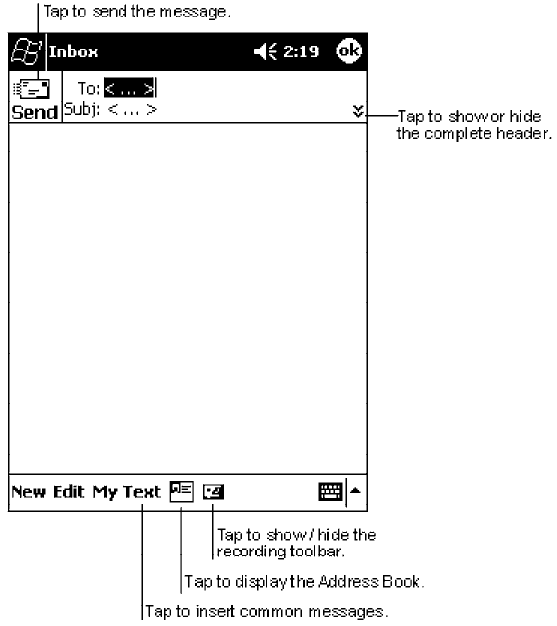
Pocket PC 2002—Chapter 2
45700 Series Color Mobile Computer User’s Manual
Composing Messages
To compose a message:
1Tap New.
2In the To field, enter an e-mail or SMS address of one or more recipi-
ents, separating them with a semicolon, or select a name from the con-
tact list by tapping the Address Book button. All e-mail addresses en-
tered in the e-mail fields in Contacts appear in the Address Book.
3Compose your message. To enter preset or frequently used messages, tap
My Text and select a message.
4Tap Send when you have finished the message. If you are working of-
fline, the message is moved to the Outbox folder and will be sent the
next time you connect.
If you are sending an SMS message and want to know if it was received,
tap Edit →Options →Request SMS text message delivery notification
before sending the message.
Pocket PC 2002Chapter —2
46 700 Series Color Mobile Computer User’s Manual
Managing E-mail Messages and Folders
By default, messages are displayed in one of five folders for each service
you have created: Inbox, Deleted Items, Drafts, Outbox, and Sent Items.
The Deleted Items folder contains messages that have been deleted on the
700 Series Computer. The behavior of the Deleted and Sent Items folders
depends on the options you have chosen. In the message list, tap Tools →
Options →the Message tab, then select your options.
If you want to organize messages into additional folders, tap Tools →
Manage Folders to create new folders. To move a message to another fold-
er, in the message list, tap and hold the message and then tap Move to on
the pop-up menu.
Folder Behavior With a Direct Connection to an E-mail Server
The behavior of the folders you create depends on whether you are using
ActiveSync, SMS, POP3, or IMAP4.
SIf you use ActiveSync:
E-mail messages in the Inbox folder in Outlook will automatically be
synchronized with your 700 Series Computer. You can select to syn-
chronize additional folders by designating them for ActiveSync. The
folders you create and the messages you move will then be mirrored on
the server. For example, if you move two messages from the Inbox fold-
er to a folder named Family, and you have designated Family for syn-
chronization, the server creates a copy of the Family folder and copies
the messages into that folder. You can then read the messages while away
from your desktop computer.
SIf you use SMS:
Messages are stored in the Inbox folder.
SIf you use POP3:
and you move e-mail messages to a folder you created, the link is broken
between the messages on the 700 Series Computer and their copies on
the mail server. The next time you connect, the mail server will see that
the messages are missing from the 700 Series Computer Inbox and de-
lete them from the server. This prevents you from having duplicate cop-
ies of a message, but it also means that you will no longer have access to
messages that you move to folders created from anywhere except the
700 Series Computer.
SIf you use IMAP4:
The folders you create and the e-mail messages you move are mirrored
on the server. Therefore, messages are available to you anytime you con-
nect to your mail server, whether it is from your 700 Series Computer
or desktop computer. This synchronization of folders occurs whenever
you connect to your mail server, create new folders, or rename/delete
folders when connected.
Pocket PC 2002—Chapter 2
47700 Series Color Mobile Computer User’s Manual
Companion Programs
The companion programs consist of Microsoft Pocket Word, Microsoft
Pocket Excel, Windows Media Player for Pocket PC, and Microsoft
Reader. To switch to a companion program on your 700 Series Computer,
tap Start →Programs, then tap the program name.
Pocket Word
Pocket Word works with Microsoft Word on your desktop computer to
give you easy access to copies of your documents. You can create new doc-
uments on your 700 Series Computer, or you can copy documents from
your desktop computer to your 700 Series Computer. Synchronize docu-
ments between your desktop computer and your 700 Series Computer so
that you have the most up-to-date content in both locations.
Creating a Document
Use Pocket Word to create documents, such as letters, meeting minutes,
and trip reports. To create a new file, tap Start →Programs →Pocket
Word →New. A blank document appears. Or, if you have selected a tem-
plate for new documents in the Options dialog box, that template appears
with appropriate text and formatting already provided. You can open only
one document at a time; when you open a second document, you will be
asked to save the first. You can save a document you create or edit in a va-
riety of formats, including Word (.DOC), Pocket Word (.PSW), Rich Text
Format (.RTF), and Plain Text (.TXT).
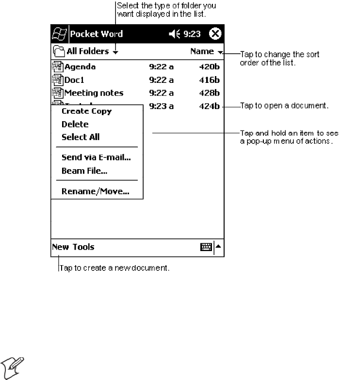
Pocket PC 2002Chapter —2
48 700 Series Color Mobile Computer User’s Manual
Pocket Word contains a list of the files stored on your 700 Series Comput-
er. Tap a file in the list to open it. To delete, make copies of, and send files,
tap and hold a file in the list. Then, select the appropriate action on the
pop-up menu.
You can enter information in Pocket Word in one of four modes (typing,
writing, drawing, and recording), which are displayed on the View menu.
Each mode has its own toolbar, which you can show and hide by tapping
the Show/Hide Toolbar button on the command bar.
Note: You can change the zoom magnification by tapping View →Zoom,
then select the percentage you want. Select a higher percentage to enter
text and a lower one to see more of your document.
If you are opening a Word document created on a desktop computer, select
Wrap to Window on the View menu so that you can see the entire
document.
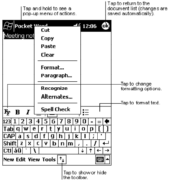
Pocket PC 2002—Chapter 2
49700 Series Color Mobile Computer User’s Manual
Typing Mode
Using the input panel, enter typed text into the document. For more infor-
mation on entering typed text, see “Basic Skills” on page 11.
To format existing text and to edit text, first select the text. You can select
text as you do in a Word document, using your stylus instead of the mouse
to drag through the text you want to select. You can search a document to
find text by tapping Edit →Find/Replace.
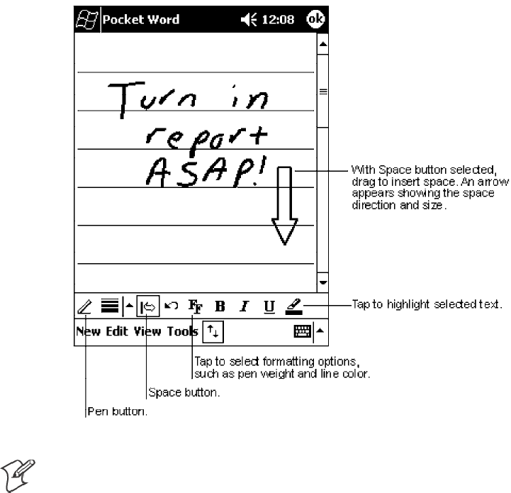
Pocket PC 2002Chapter —2
50 700 Series Color Mobile Computer User’s Manual
Writing Mode
In writing mode, use your stylus to write directly on the screen. Ruled
lines are displayed as a guide, and the zoom magnification is greater than
in typing mode to allow you to write more easily. For more information on
writing and selecting writing, see “Basic Skills” on page 11.
Note: If you cross three ruled lines in a single stylus stroke, the writing
becomes a drawing, and can be edited and manipulated as described in
“Drawing Mode” on the next page.
Written words are converted to graphics (metafiles) when a Pocket Word
document is converted to a Word document on your desktop computer.
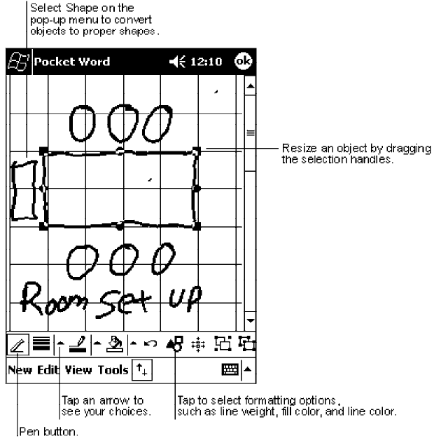
Pocket PC 2002—Chapter 2
51700 Series Color Mobile Computer User’s Manual
Drawing Mode
In drawing mode, use your stylus to draw on the screen. Grid lines appear
as a guide. When you lift your stylus off the screen after the first stroke,
you will see a drawing box indicating the boundaries of the drawing. Every
subsequent stroke within or touching the drawing box becomes part of the
drawing. For more information on drawing and selecting drawings, see
“Basic Skills” on page 11.
Recording Mode
In recording mode, embed a recording into your document. Recordings are
saved as .WAV files. For more information on recording, see “Basic Skills”
on page 11.
For more information on using Pocket Word, tap Start →Help.
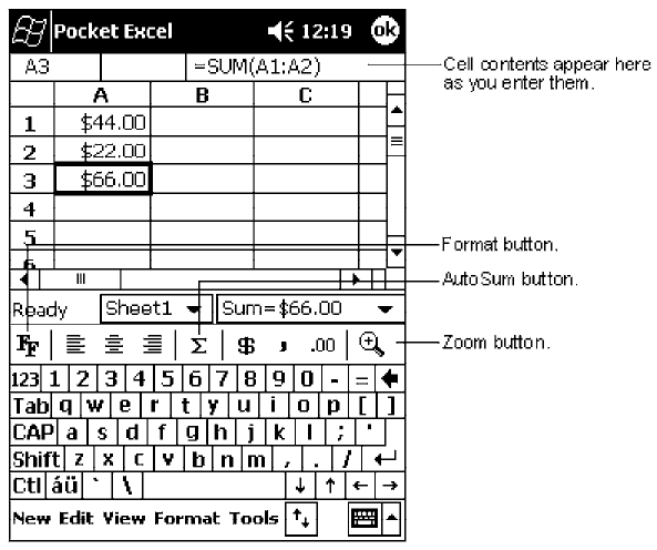
Pocket PC 2002Chapter —2
52 700 Series Color Mobile Computer User’s Manual
Pocket Excel
Pocket Excel works with Microsoft Excel on your desktop computer to
give you easy access to copies of your workbooks. You can create new
workbooks on your 700 Series Computer, or you can copy workbooks
from your desktop computer to your 700 Series Computer. Synchronize
workbooks between your desktop computer and your 700 Series Comput-
er so that you have the most up-to-date content in both locations.
Creating a Workbook
Use Pocket Excel to create workbooks, such as expense reports and mileage
logs. To create a new file, tap Start →Programs →Pocket Excel →New.
A blank workbook appears. Or, if you have selected a template for new
workbooks in the Options dialog box, that template appears with
appropriate text and formatting already provided. You can open only one
workbook at a time; when you open a second workbook, you will be asked
to save the first. You can save a workbook you create or edit in a variety of
formats, including Pocket Excel (.PXL) and Excel (.XLS).
Pocket Excel contains a list of the files stored on your 700 Series Comput-
er. Tap a file in the list to open it. To delete, make copies of, and send files,
tap and hold a file in the list. Then select the appropriate action from the
pop-up menu.
Pocket Excel provides fundamental spreadsheet tools, such as formulas,
functions, sorting, and filtering. To display the toolbar, tap View →
Toolbar.

Pocket PC 2002—Chapter 2
53700 Series Color Mobile Computer User’s Manual
Note: If your workbook contains sensitive information, you can protect it
with a password. To do so, open the workbook, tap Edit →Password.Ev-
ery time you open the workbook, you will need to enter the password, so
choose one that is easy for you to remember but hard for others to guess.
Tips for Working in Pocket Excel
Note the following when working in large worksheets in Pocket Excel:
SView in full-screen mode to see as much of your worksheet as possible.
Tap View →Full Screen. To exit full-screen mode, tap Restore.
SShow and hide window elements. Tap View and then tap the elements
youwanttoshoworhide.
SFreeze panes on a worksheet. First select the cell where you want to
freeze panes. Tap View →Freeze Panes. You might want to freeze the
top and leftmost panes in a worksheet to keep row and column labels
visible as you scroll through a sheet.
SSplit panes to view different areas of a large worksheet. Tap View →
Split. Then drag the split bar to where you want it. To remove the split,
tap View →Remove Split.
SShow and hide rows and columns. To hide a hidden row or column, se-
lect a cell in the row or column you want to hide. Then tap Format ,
Row or Column →Hide. To show a hidden row or column, tap Tools
→Go To, and then type a reference that is in the hidden row or co-
lumn. Then tap Format →Row or Column →Unhide.
For more information on using Pocket Excel, tap Start →Help.
MSN Messenger
Note: MSN Messenger is only available on the Premium Edition of Pocket
PC 2002.
MSN Messenger on your 700 Series Computer is an instant messaging
program that lets you:
SSee who is online.
SSend and receive instant messages.
SHave instant message conversations with groups of contacts.
To use MSN Messenger, you must have a Microsoft Passport account or a
Microsoft Exchange e-mail account. You must have a Passport to use MSN
Messenger Service. If you have a Hotmail or MSN account, you already
have a Passport. Once you have obtained either a Microsoft Passport or a
Microsoft Exchange account, you are ready to set up your account.
SSign up for a Microsoft Passport account at http://www.passport.com.
SGet a free Microsoft Hotmail e-mail address at http://www.hotmail.com.
To switch to MSN Messenger, tap Start →Programs →MSN Messenger.
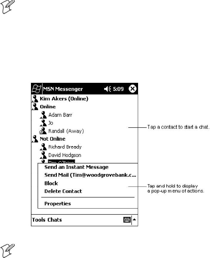
Pocket PC 2002Chapter —2
54 700 Series Color Mobile Computer User’s Manual
Setting Up
Before you can connect, you must enter Passport or Exchange account in-
formation. To set up an account and sign in:
1In the Tools menu, tap Options.
2In the Accounts tab, enter your Passport or Exchange account informa-
tion.
3To sign in, tap the sign-in screen and enter your e-mail address and pass-
word.
Note: If you already use MSN Messenger on your desktop computer, your
contacts will show up on your 700 Series Computer without being added
again.
Working with Contacts
The MSN Messenger window shows all of your messenger contacts at a
glance, divided into Online and Not Online categories. From this view,
while connected, you can chat, send e-mail, block the contact from chat-
ting with you, or delete contacts from your list using the pop-up menu.
Note: To see others online without being seen, in the Tools menu, tap My
Status →Appear Offline.
If you block a contact, you will appear offline but will remain on the
blocked contact’ s list. To unblock a contact, tap and hold the contact, then
tap Unblock on the pop-up menu.
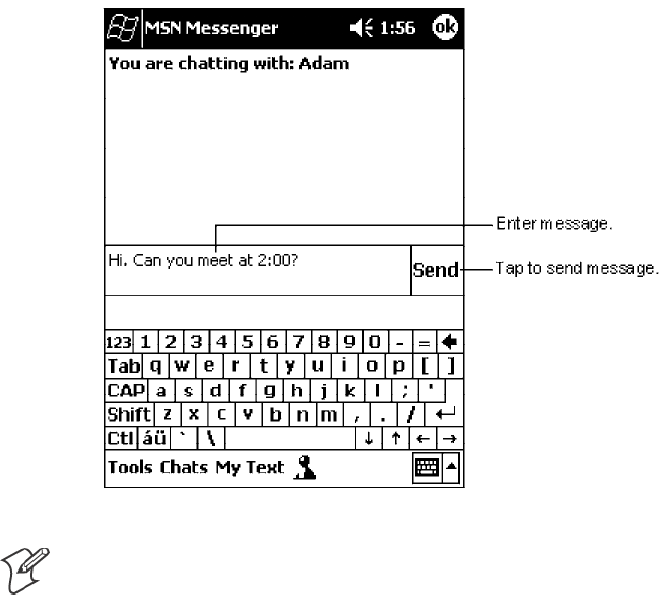
Pocket PC 2002—Chapter 2
55700 Series Color Mobile Computer User’s Manual
Chatting with Contacts
Tap a contact name to open a chat window. Enter your message in the text
entry area at the bottom of the screen, or tap My Text to enter a preset
message, and tap Send. To invite another contact to a multi-user chat, in
the Tools menu, tap Invite and tap the contact you want to invite.
Note: To switch back to the main window without closing a chat, tap the
Contacts button. To revert back to your chat window, tap Chats and select
the person whom you were chatting with.
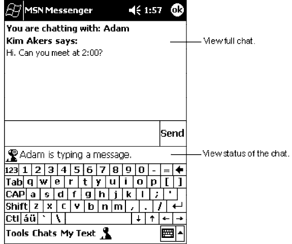
Pocket PC 2002Chapter —2
56 700 Series Color Mobile Computer User’s Manual
To know if the contact you are chatting with is responding, look for the
message under the text entry area.
For more information on using MSN Messenger, tap Start →Help.
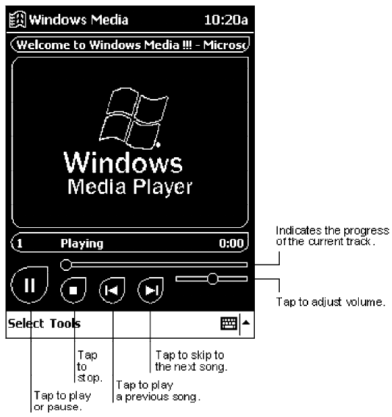
Pocket PC 2002—Chapter 2
57700 Series Color Mobile Computer User’s Manual
Windows Media Player for Pocket PC
Use Microsoft Windows Media Player for Pocket PC to play digital audio
and video files that are stored on your 700 Series Computer or on a net-
work. To switch to Windows Media Player for Pocket PC, tap Start →
Programs →Windows Media.
Use Microsoft Windows Media Player on your desktop computer to copy
digital audio and video files to your Pocket PC. You can play Windows
Media and MP3 files on your Pocket PC.
For more information about using Windows Media Player for Pocket PC,
tap Start →Help.
Pocket PC 2002Chapter —2
58 700 Series Color Mobile Computer User’s Manual
Microsoft Reader
Use Microsoft Reader to read eBooks on your 700 Series Computer.
Download books to your desktop computer from your favorite eBook Web
site. Then, use ActiveSync to copy the book files to your activated 700 Se-
ries Computer. The books appear in the Reader Library, where you can tap
them in the list to open them. Each book consists of a cover page, an op-
tional table of contents, and the pages of the book. You can:
SPage through the book by using the Up/Down control on your 700 Se-
ries Computer or by tapping the page number on each page.
SAnnotate the book with highlighting, bookmarks, notes, and drawings.
SSearch for text and look up definitions for words.
The Guidebook contains all the information you will need to use the soft-
ware. To open the Guidebook, tap Help on the Reader command bar. Or,
on a book page, tap and hold on the book title, and then tap Help on the
pop-up menu. To switch to Microsoft Reader, tap Start →Programs →
Microsoft Reader.
Getting Books on Your 700 Series Computer
You can download book files from the Web. Just visit your favorite eBook
retailer and follow the instructions to download the book files.
Sample books and a dictionary are also included in the MSReader folder in
the Extras folder on the Pocket PC Companion CD.
Use ActiveSync to download the files from your desktop computer to your
activated mobile computer as described in the Read Me file in the
MSReader folder.
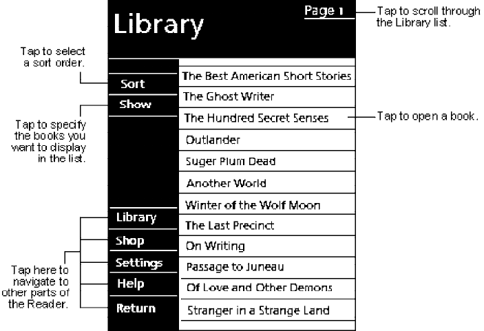
Pocket PC 2002—Chapter 2
59700 Series Color Mobile Computer User’s Manual
Using the Library
The Library is your Reader home page; it displays a list of all books stored
on your 700 Series Computer or storage card. To open the Library:
1On the Reader command bar, tap Library.
2On a book page, tap the book title, then tap Library on the pop-up
menu.
3To open a book, tap its title in the Library list.
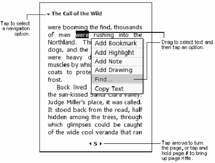
Pocket PC 2002Chapter —2
60 700 Series Color Mobile Computer User’s Manual
Reading a Book
Each book consists of a cover page, an optional table of contents, and the
pages of the book. Navigation options are listed in the bottom portion of
the cover page.
The first time you open a book, you will probably want to go to the first
page or to the table of contents, if there is one. Subsequently, whenever
you open the book, you will be automatically taken to the last page read.
In addition to the text, each book page includes a page number and book
title.
You can also page through a book by using the Up/Down control on your
700 Series Computer.
Pocket PC 2002—Chapter 2
61700 Series Color Mobile Computer User’s Manual
Using Reader Features
Reading a book electronically gives you several options not available with
paper books. These options are available from any book page.
Select text by dragging across the text on the page. Then, tap an option on
the pop-up menu, as described here:
SSearching for Text
Find text in a book by tapping Find on the pop-up menu. Enter the
word you want to search for, and tap the desired Find option. Reader
highlights found text on the page. To close Find, tap outside the box.
To return to your original page, tap the title and then tap Return on the
pop-up menu.
SCopying Text
You can copy text from books that support this feature into any pro-
gram that accepts text. On a book page, select the text you want to copy.
Then, tap Copy Text on the pop-up menu. The text can be pasted into
the program of your choice.
SAdding Bookmarks
When you add a bookmark to a book, a color-coded bookmark icon
appears in the right margin. You can add multiple bookmarks to a book.
Then, from anywhere in the book, tap the bookmark icon to go to the
bookmarked page.
SHighlighting Text
When you highlight text, it appears with a colored background.
SAttaching Notes to Text
When you attach a note to text, you enter the text in a notepad that ap-
pears on top of the book page. A Note icon will display in the left mar-
gin. To show or hide the note, tap the icon.
SAdding Drawings
When you add a drawing, a Drawing icon appears in the bottom-left
corner of the page, and drawing tools appear across the bottom of the
page. Draw by dragging your stylus.
SAnnotations Index
To see a list of a book’ s annotations, including bookmarks, highlights,
text notes, and drawings, tap Annotations Index on the book’ s cover
page. You can tap an entry in the list to go to the annotated page.
Removing a Book
When you finish reading a book, you can delete it to conserve space on
your 700 Series Computer. If a copy of the book is stored on your desktop
computer, you can download it again at any time.
To remove a book from your 700 Series Computer, tap and hold the title
in the Library list, and then tap Delete on the pop-up menu.

Pocket PC 2002Chapter —2
62 700 Series Color Mobile Computer User’s Manual
Pocket Internet Explorer
Note: The Professional Edition of Pocket Internet Explorer does not sup-
port WAP pages.
Use Microsoft Pocket Internet Explorer to view Web or WAP pages in ei-
ther of these ways:
SDuring synchronization with your desktop computer, download your
favorite links and mobile favorites that are stored in the Mobile Favor-
ites subfolder in Internet Explorer on the desktop computer.
SConnect to an ISP or network and browse the Web. To do this, you will
need to create the connection first, as described in “Getting Connected”
on page 67.
When connected to an ISP or network, you can also download files and
programs from the Internet or intranet.
To switch to Pocket Internet Explorer, tap Start →Internet Explorer.
The Mobile Favorites Folder
Only items stored in the Mobile Favorites subfolder in the Favorites folder
in Internet Explorer on your desktop computer will be synchronized with
your 700 Series Computer. This folder was created automatically when
you installed ActiveSync.
Favorite Links
During synchronization, the list of favorite links in the Mobile Favorites
folder on your desktop computer is synchronized with Pocket Internet Ex-
plorer on your 700 Series Computer. Both computers are updated with
changes made to either list each time you synchronize. Unless you mark
the favorite link as a mobile favorite, only the link will be downloaded to
your 700 Series Computer, and you will need to connect to your ISP or
network to view the content. For more information on synchronization,
see ActiveSync Help on the desktop computer.
Mobile Favorites
If you are using Microsoft Internet Explorer 5.0 or later on your desktop
computer, you can download mobile favorites to your 700 Series Comput-
er. Synchronizing mobile favorites downloads Web content to your 700
Series Computer so that you can view pages while you are disconnected
from your ISP and desktop computer.
Use the Internet Explorer plug-in installed with ActiveSync to create mo-
bile favorites quickly. To create a mobile favorite:
1In Internet Explorer on your desktop computer, click Tools →Create
Mobile Favorite.
2To change the link name, enter a new name in the Name box.
3Optionally, in Update, select a desired update schedule.

Pocket PC 2002—Chapter 2
63700 Series Color Mobile Computer User’s Manual
4Click OK. Internet Explorer downloads the latest version of the page to
your desktop computer.
5If you want to download the pages that are linked to the mobile favorite
you just created, in Internet Explorer on the desktop computer,
right-click the mobile favorite just created and then click Properties.In
the Download tab, specify the number of links deep you want to
download. To conserve 700 Series Computer memory, go only one level
deep.
6Synchronize your 700 Series Computer and desktop computer. Mobile
favorites that are stored in the Mobile Favorites folder in Internet Ex-
plorer are downloaded to your 700 Series Computer.
Note: If you did not specify an update schedule in step 3 above, you will
need to manually download content to keep the information updated on
your desktop computer and 700 Series Computer. Before synchronizing
with your 700 Series Computer, in Internet Explorer on your desktop
computer, click Tools →Synchronize. You will see the last time content
was downloaded to the desktop computer, and you can manually download
content if needed.
You can add a button to the Internet Explorer toolbar for creating mobile
favorites. In Internet Explorer on your desktop computer, click View →
Toolbars →Customize.
Mobile favorites take up storage memory on your 700 Series Computer.
To minimize the amount of memory used:
SIn the settings for the Favorites information, type in ActiveSync options,
turn off pictures and sounds, or stop some mobile favorites from being
downloaded to the 700 Series Computer. For more information, see Ac-
tiveSync Help.
SLimit the number of downloaded linked pages. In Internet Explorer on
the desktop computer, right-click the mobile favorite you want to
change and then Properties.IntheDownload tab, specify “0” or “1” for
the number of linked pages you want to download.
Pocket PC 2002Chapter —2
64 700 Series Color Mobile Computer User’s Manual
Using AvantGo Channels
AvantGo is a free interactive service that gives you access to personalized
content and thousands of popular Web sites. You subscribe to AvantGo
channels directly from your 700 Series Computer. Then, you synchronize
your 700 Series Computer and desktop computer, or connect to the Inter-
net to download the content. For more information, visit the AvantGo
Web site. To sign up for AvantGo:
1In ActiveSync options on the desktop computer, turn on synchroniza-
tion for the AvantGo information type.
2In Pocket Internet Explorer on your 700 Series Computer, tap the Fa-
vorites button to display your list of favorites.
3Tap t he AvantGo Channels link.
4Tap t he Activate button.
5Follow the directions on the screen. You will need to synchronize your
700 Series Computer with your desktop computer and then tap the My
Channels button to complete the AvantGo setup.
When synchronization is complete, tap the AvantGo Channels link in
your list of favorites to see a few of the most popular channels. To add or
remove channels, tap the Add or Remove link.
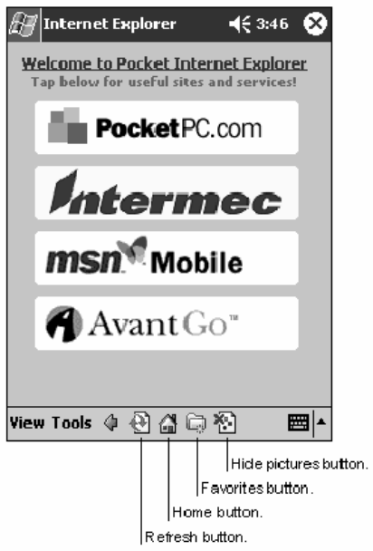
Pocket PC 2002—Chapter 2
65700 Series Color Mobile Computer User’s Manual
Using Pocket Internet Explorer
You can use Pocket Internet Explorer to browse mobile favorites and chan-
nels that have been downloaded to your 700 Series Computer without
connecting to the Internet. You can also connect to the Internet through
an ISP or a network connection and browse the Web.
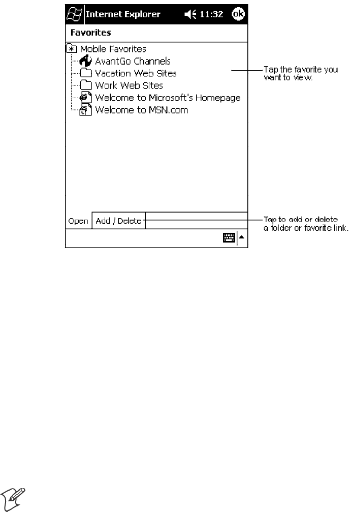
Pocket PC 2002Chapter —2
66 700 Series Color Mobile Computer User’s Manual
Viewing Mobile Favorites and Channels
1Tap t he Favorites button to display your list of favorites.
2Tap the page you want to view.
You will see the page that was downloaded the last time you synchronized
with your desktop computer. If the page is not on your 700 Series Com-
puter, the favorite will be dimmed. You will need to synchronize with your
desktop computer again to download the page to your 700 Series Comput-
er, or connect to the Internet to view the page.
Browsing the Internet
1Set up a connection to your ISP or corporate network using Connec-
tions, as described in “Getting Connected” on page 67.
2To connect and start browsing, do one of the following:
STap t he Favorites button, and then tap the favorite you want to view.
STap View →Address Bar. In the address bar that appears at the top
of the screen, enter the Web address you want to visit and then tap
Go. Tap the arrow to choose from previously entered addresses.
Note: To add a favorite link while using the 700 Series Computer, go to
the page you want to add, tap and hold on the page, and tap Add to
Favorites.

Pocket PC 2002—Chapter 2
67700 Series Color Mobile Computer User’s Manual
Getting Connected
You can use your 700 Series Computer to exchange information with oth-
er 700 Series Computers as well as your desktop computer, a network, or
the Internet. You have the following connection options:
SUse the infrared (IR) port on your 700 Series Computer to send and
receive files between two 700 Series Computers. If this is the method
you want to use, see “Transferring Items Using Infrared”below.
SConnect to your ISP. Once connected, you can send and receive e-mail
messages by using Inbox and view Web or WAP pages by using Pocket
Internet Explorer. The communication software for creating an ISP con-
nection is already installed on your 700 Series Computer. Your service
provider will provide software needed to install other services, such as
paging and fax services. If this is the method you want to use, see “Con-
necting to an Internet Service Provider” on page 68.
SConnect to the network at your company or organization where you
work. Once connected, you can send and receive e-mail messages by
using Inbox, view Web or WAP pages by using Pocket Internet Explorer,
and synchronize with your desktop computer. If this is the method you
want to use, see “Connecting to Work” on page 70.
SConnect to your desktop computer to synchronize remotely. Once con-
nected, you can synchronize information such as your Pocket Outlook
information. If this is the method you want to use, see ActiveSync Help
on your desktop computer or Connections Help on the 700 Series
Computer.
Transferring Items Using Infrared
Using infrared (IR), you can send and receive information, such as con-
tacts and appointments, between two 700 Series Computers.
Sending Information
1Switch to the program where you created the item you want to send and
locate the item in the list.
2Align the IR ports so that they are unobstructed and within a close
range.
3Tap and hold the item, and tap Beam Item on the pop-up menu.
Note: You can also send items, but not folders, from File Explorer. Tap
and hold the item you want to send, and then tap Beam File on the pop-
up menu.
Receiving Information
1Align the IR ports so that they are unobstructed and within a close
range.
2Have the owner of the other 700 Series Computer send the information
to you. Your 700 Series Computer will automatically receive it.
Pocket PC 2002Chapter —2
68 700 Series Color Mobile Computer User’s Manual
Connecting to an Internet Service Provider
You can connect to your ISP, and use the connection to send and receive
e-mail messages and view Web or WAP pages. You can connect to your
ISP in one of two ways:
SCreate a modem connection. If this is the method you want to use, see
“Creating a Modem Connection to an ISP”below.
SUse an Ethernet card and a net tap to connect to the network. If this is
the method you want to use, see “Creating an Ethernet Connection to an
ISP” on page 69.
Creating a Modem Connection to an ISP
1Obtain the following information from your ISP. Some ISPs require in-
formation in front of the user name, such as MSN/username.
SISP dial-up access telephone number
SUser name
SPassword
STCP/IP settings
2If your 700 Series Computer does not have a built-in modem, install a
modem card, or use or use a NULL modem cable and appropriate
adapters to connect an external modem to your 700 Series Computer
through the serial port.
3Tap Start →Settings →the Connections tab →Connections.Under
The Internet settings, select Internet Settings →Modify.
4In the Modem tab, tap New.
5Enter a name for the connection, such as “ISP Connection.”
6In Select a modem list, select your modem type. If your modem type
does not appear, try reinserting the modem card. If you are using an ex-
ternal modem that is connected to your 700 Series Computer with a
cable, select “Hayes Compatible on COM1.”
7You should not need to change any settings in Advanced.MostISPs
now use a dynamically-assigned address. If the ISP you are connecting
to does not use a dynamically-assigned address, tap Advanced →the
TCP/IP tab, then enter the address. When finished, tap OK →Next.
8Enter the access phone number, and tap Next.
9Select other desired options, and tap Finish.
10 In the Dialing Locations tab, specify your current location and phone
type (most phone lines are tone). These settings will apply to all connec-
tions you create.
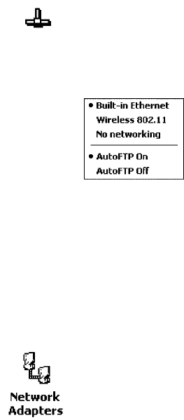
Pocket PC 2002—Chapter 2
69700 Series Color Mobile Computer User’s Manual
To start the connection, simply start using one of the following programs.
Your 700 Series Computer will automatically begin connecting. Once con-
nected, you can:
SSend and receive e-mail messages by using Inbox. Before you can use
Inbox, you need to provide the information it needs to communicate
with the e-mail server. For specific instructions, see “Connecting Directly
to an E-mail Server” on page 72.
SVisit Web and WAP pages by using Pocket Internet Explorer. For more
information, see “Pocket Internet Explorer” on page 62.
SSend and receive instant messages with MSN Messenger. For more in-
formation, see “MSN Messenger” on page 53.
Creating an Ethernet Connection to an ISP
1You do not need to create a new connection on your 700 Series Com-
puter. Instead, you must purchase a dock to enable on-board Ethernet
or purchase a CompactFlash Ethernet card that is compatible with your
700 Series Computer.
2Obtain the following information from your ISP:
SUser name
SPassword
SDomain name
3Insert the Ethernet card into your 700 Series Computer. For instruc-
tions on inserting and using the Ethernet card, see the owner’ s manual.
If using an on-board Ethernet, place your 700 Series Computer in a dock,
tap Start →Today, then look in the System Tray for the Ethernet icon
(shown left). If not there, then tap the antenna icon for the NDISTRAY
pop-up menu and select Built-in Ethernet from the menu.
4The first time you insert the card, Network Settings will appear
automatically so that you can configure the Ethernet card. Most
networks use DHCP, so you should not have to change these settings
unless your network administrator instructs you to do so. Tap OK.(Ifit
does not appear or to change settings later, tap Start →Settings →the
Connections tab →Network, tap the adapter you want to change, and
then tap Properties.)
SIf using an on-board Ethernet, then select Start →Settings →the
Connections tab →Network Adapters. Select “NE2000 Compatible
Ethernet Driver” from the list of adapters installed, then tap Proper-
ties to configure the Ethernet driver.
Pocket PC 2002Chapter —2
70 700 Series Color Mobile Computer User’s Manual
5Connect the Ethernet card or dock to the network by using a network
cable. For information, see your owner’ s manual.
6Tap Start →Settings →the Connections tab →Connections.From
the My network card connects to list, select “Internet.”
To start the connection, simply start using one of the programs listed in
the preceding section. Once connected, you can perform the same activi-
ties as listed in the preceding section.
Connecting to Work
If you have access to a network at work, you can send e-mail messages,
view intranet pages, synchronize your 700 Series Computer, and possibly
access the Internet. You can connect to work in one of two ways:
SCreate a modem connection by using a RAS (Remote Access Server) ac-
count. Before you can create this modem connection, your network ad-
ministrator will need to set up a RAS account for you. If this is the
method you want to use, see “Creating a Modem Connection to Work”
below. Your network administrator may also give you VPN settings.
SUse an Ethernet card and a net tap to connect to the network. If this is
the method you want to use, see “Creating an Ethernet Connection to
Work” on page 71.
Creating a Modem Connection to Work
1Get the following information from your network administrator:
SDial-up access telephone number
SUser name
SPassword
SDomain name
STCP/IP settings
2If your 700 Series Computer does not have a built-in modem, install a
modem card.
3Tap Start →Settings →the Connections tab →Connections.Under
The Internet settings, select Internet Settings and tap Modify.
4In the Modem tab, tap New.
5Enter a name for the connection, such as “Company Connection.”
6In the Select a modem list, select your modem type. If your modem
type does not appear, try reinserting the modem card. If you are using
an external modem that is connected to your 700 Series Computer with
a cable, select “Hayes Compatible on COM1.”
7You should not need to change any settings in Advanced. Most servers
now use a dynamically-assigned address. If the server you are connecting
to does not use a dynamically-assigned address, tap Advanced →the
TCP/IP tab and then enter the address. When finished, tap OK →
Next.
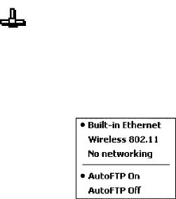
Pocket PC 2002—Chapter 2
71700 Series Color Mobile Computer User’s Manual
8Enter the access phone number, and tap Next.
9Select other desired options, and tap Finish.
10 In the Dialing Locations tab, specify your current location and phone
type (most phone lines are tone). These settings will apply to all connec-
tions you create.
To start the connection, start using one of the following programs. Your
700 Series Computer will automatically begin connecting. Once con-
nected, you can:
SSend and receive e-mail messages by using Inbox. Before you can use
Inbox, you need to provide the information it needs to communicate
with the e-mail server. For specific instructions, see “Connecting Directly
to an E-mail Server” on page 72.
SVisit Internet or intranet Web or WAP pages via Pocket Internet Explor-
er.
SSend and receive instant messages with MSN Messenger. For more in-
formation, see “MSN Messenger” on page 53.
SSynchronize. For more information, see ActiveSync Help on the desktop
computer.
Creating an Ethernet Connection to Work
1You do not need to create a new connection on your 700 Series Com-
puter. Instead, you must purchase a dock to enable on-board Ethernet
or purchase a CompactFlash Ethernet card that is compatible with your
700 Series Computer.
2Obtain the following information from your ISP:
SUser name
SPassword
SDomain name
3Insert the Ethernet card into your 700 Series Computer. For instruc-
tions on inserting and using the Ethernet card, see the owner’ s manual.
SIf using an on-board Ethernet, place your 700 Series Computer in a
dock, tap Start →Today, then look in the System Tray for the Ether-
net icon (shown left). If not there, then tap the antenna icon for the
NDISTRAY pop-up menu and select Built-in Ethernet from the
menu.

Pocket PC 2002Chapter —2
72 700 Series Color Mobile Computer User’s Manual
4The first time you insert the card, Network Settings will appear
automatically so that you can configure the Ethernet card. Most
networks use DHCP, so you should not have to change these settings
unless your network administrator instructs you to do so. Tap OK.(Ifit
does not appear or to change settings later, tap Start →Settings →the
Connections tab →Network, tap the adapter you want to change, and
then tap Properties.)
SIf using an on-board Ethernet, then select Start →Settings →the
Connections tab →Network Adapters. Select “NE2000 Compatible
Ethernet Driver” from the list of adapters installed, then tap Proper-
ties to configure the Ethernet driver.
5Connect the Ethernet card or dock to the network by using a network
cable. For information, see your owner’ s manual.
6To synchronize your 700 Series Computer, tap Start →ActiveSync.In
the Tools menu, tap Options.→the PC tab, select Include PC when
synchronizing remotely and connect to, and select your computer’ s
name. Remote synchronization with a desktop computer will work only
if a partnership is set up with that computer through ActiveSync and
ActiveSync is set to allow remote connections. Other restrictions apply.
For more information, see ActiveSync Help on the desktop computer.
To start the connection, simply start using one of the programs listed in
the preceding section. Once connected, you can perform the same activi-
ties as listed in the preceding section.
Ending a Connection
To disconnect, do one of the following:
SWhen connected via dial-up or VPN, tap the Connection icon (shown
left) on your navigation bar, and then tap End.
SWhen connected via cable or cradle, detach your 700 Series Computer
from the cable or cradle.
SWhen connected via Infrared, move the 700 Series Computer away
from the PC.
SWhen connected via a network (Ethernet) card, remove the card from
your 700 Series Computer.
Connecting Directly to an E-mail Server
You can set up a connection to an e-mail server so that you can send and
receive e-mail messages by using a modem or network connection and In-
box on your 700 Series Computer.
Note: The ISP or network must use a POP3 or IMAP4 e-mail server and
an SMTP gateway.
You can use multiple e-mail services to receive your messages. For each e-
mail service you intend to use, first set up and name the e-mail service. If
you use the same service to connect to different mailboxes, set up and
name each mailbox connection.
Pocket PC 2002—Chapter 2
73700 Series Color Mobile Computer User’s Manual
Setting Up an E-mail Service
SIn Inbox on your 700 Series Computer, tap Services →New Service.
Follow the directions in the New Service wizard.
For an explanation of a screen, tap Start →Help. When finished, to con-
nect to your e-mail server, tap Services →Connect. For more information
on using the Inbox program, see “Inbox: Sending and Receiving E-mail Mes-
sages” on page 42.
Pocket PC 2002Chapter —2
74 700 Series Color Mobile Computer User’s Manual

75700 Series Color Mobile Computer User’s Manual
Installing Applications
3
There are multiple ways to get an application to your 700 Series Color
Mobile Computer; just as there are multiple ways to package the applica-
tion for delivery.
Installing ApplicationsChapter —3
76 700 Series Color Mobile Computer User’s Manual
Packaging an Application
Use any of the following methods to package an application for installa-
tion:
SFor very simple applications, the application itself might be the only file
that needs to be delivered.
SIt could be a directory structure that contains the application, support-
ing files like ActiveX controls, DLLs, images, sound files, and data files.
SVia a CAB file.
Consider either of the following when choosing a location into which to
store your application:
SIn the basic 700 Series Computer, there are no built-in storage options
other than the Object Store. The Object Store is RAM that looks like a
disk. Anything copied here will be deleted when a cold-boot is per-
formed on the 700 Series Computer.
SIf the optional SecureDigital or CompactFlash storage card is in the sys-
tem, then consider this card the primary location for placing an applica-
tions install files. The following folders represent either card:
SThe SecureDigital storage card creates the “\SDMMC Disk” folder.
SThe CompactFlash storage card creates the “\Storage Card” folder.
SFiles copied to either of these locations will be safe when a cold-boot is
performed on a 700 Series Computer - providing the AutoRun system is
installed onto the storage card. You can find this system on the Recovery
CD. Copying a CAB file to the “\CABFILES” folder on one of these
cards will automatically extract that CAB file on every cold boot to en-
sure that your system is properly set up. See page 82 for more details on
how this works.
Installing Applications
Consider any of the following options to get the package to the preferred
location on your 700 Series Computer.
SMicrosoft ActiveSync
SFTP Server (page 78)
SApplication Manager in Unit Manager (page 78)
SSecureDigital or CompactFlash storage card (page 78)
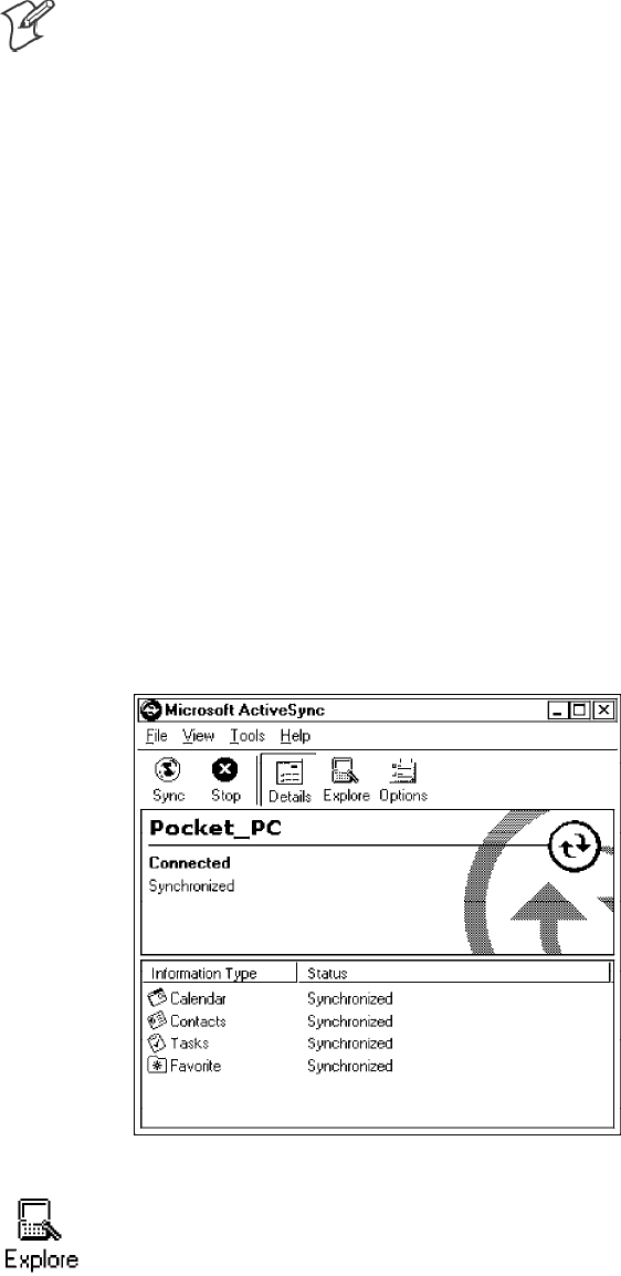
Installing Applications—Chapter 3
77700 Series Color Mobile Computer User’s Manual
Using Microsoft ActiveSync
Note: These instructions assume that the 700 Color Management Tools
portion of the 700 Series Color Software Tools CD was installed onto your
desktop.
The Microsoft ActiveSync tool is located on the 700C Companion CD,
which contains Microsoft products, such as Outlook and ActiveSync. See
Chapter 2, “Pocket PC 2002,” for information about this tool as provided
by Microsoft Corporation.
This can be a serial, USB, Ethernet, InfraRed, or 802.11b ActiveSync con-
nection. Files can then be copied using File Explorer on a PC or a laptop
computer. This option is usually only good when updating a few 700 Se-
ries Computers.
These instructions assume that Microsoft ActiveSync had been installed
onto your desktop computer and is up and running. If not, go to Chapter
2, “Pocket PC 2002,” for an URL from which you can download the latest
application.
1Connect your 700 Series Computer to your desktop computer via an
ActiveSync cable or IrDA.
2Wait for a “Connected” message to appear in the Microsoft ActiveSync
application to signal a connection to the 700 Series Computer. If neces-
sary, select File →Get Connected to initiate a connection.
3Click Explore to access the Mobile Device directory on your 700 Series
Computer.
Installing ApplicationsChapter —3
78 700 Series Color Mobile Computer User’s Manual
4From your desktop, select Start →Windows Explorer, then browse the
applicable path for any of the system files needed for your 700 Series
Computer (listed with their paths). Select to highlight the appropriate
file, right-click the file for a pop-up menu, then select Copy.
SBase operating system files:
“C:\Intermec\Intermec 700 Color Mgmt Tools\Drive Images”
SCAB files:
“C:\Intermec\Intermec 700 Color Mgmt Tools\Cab Files”
5Within the Mobile Device directory, go to the directory where you want
the files located on the 700 Series Computer, do a right-click for a pop-
up menu, then select Paste.
6When all of the files are pasted, perform a warm-boot on the 700 Series
Computer. When the computer reboots, wait for the LED on the top
left of your keypad to stop blinking. Tap Start →Programs →File Ex-
plorer to locate the newly copied executable files, then tap these files to
activate their utilities.
Using the FTP Server
The 700 Series Computer has a built-in FTP Server that connects to a net-
work via Ethernet or 802.11b. This “ftp”s to the IP address of the 700 Se-
ries Computer and places files. The benefit of using FTP is that a script
can be created that will automate the process of copying files to the 700
Series Computer. This option is good for when a large number of 700 Se-
ries Computers need to be updated. See Chapter 7, “Programming,” for
more information.
Using the Application Manager in Unit Manager
This requires the 700 Series Computer to connect to the network via
Ethernet or 802.11b. The process is still manual so it would take longer
than the FTP method but it would still be a better option than ActiveSync
where many 700 Series Computers need to be updated. The Unit Manager
applications are available on the 700 Series Color Unit Manager CD-ROM.
For more information, consult your Intermec sales representative.
Using a Storage Card
The following steps pertain to installing an application using a storage
card.
Copying to a CompactFlash Card
Follow the steps below to install your application on the device using a
CompactFlash storage card:
1Suspend the 700 Series Color Mobile Computer and remove its Com-
pactFlash drive, which holds a SanDisk CompactFlash storage card.
2Using a CompactFlash Adapter card, place the CompactFlash Drive in
your desktop PC card drive.
Installing Applications—Chapter 3
79700 Series Color Mobile Computer User’s Manual
3Create a subdirectory on the PCMCIA CompactFlash drive in which to
store your application.
4Add the autorun system to the storage card using the CEImager
application. See the Software Tools User’ s Manual for information about
CEImager.
5Copy your application, data files, and all required DLLs and drivers to
the subdirectory created on the CompactFlash drive.
6Add your application to the AUTOUSER.DAT file on the
“\Storage Card\2577” directory that contains the following statement,
where your directory is the directory on the CompactFlash storage card
where the application was installed, and yourapp.exe is the name of your
application. Finish the “RUN=” statement with a carriage return line-
feed combination. There may be multiple run statements in the file.
RUN=\<your directory>\<yourapp.exe>
7Remove the CompactFlash drive from your desktop computer and rein-
stall it into the 700 Series Computer.
8Warm-boot the 700 Series Computer to add these files to the Compact-
Flash storage card.
If the AUTOUSER.DAT file is found and the “RUN=” statement is cor-
rect, then the task manager will launch and execute your program on start-
up.
Copying to a SecureDigital Storage Card
Do the same steps as for the CompactFlash storage Card, except replace
the “\Storage Card\2577” directory with the “\SDMMC Disk\2577” direc-
tory.
Updating the System Software
You can use the Recovery CD to reinstall or update the operating system
software on the 700 Series Color Computer. For more information, con-
tact your Intermec sales representative.
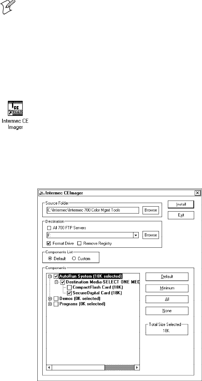
Installing ApplicationsChapter —3
80 700 Series Color Mobile Computer User’s Manual
Application Migration
Note: These instructions assume that the 700 Color Management Tools
portion of the 700C Software Tools CD was installed onto your desktop
and that a storage card has been added to the base configuration of the 700
Color Computer.
The following steps are required to ensure that the following will happen
on a cold-boot:
SCAB files can be restored,
Sapplications will automatically start,
Sand the registry will be restored.
Do the following for the cold-boot procedure:
1From your desktop, double-click the Intermec CE Imager desktop icon
to access the Intermec CEImager application. If this icon is not on your
desktop, then double-click the CEIMAGER.EXE executable from the
“C:\Intermec\Intermec 700 Color Mgmt Tools\Tools\CEImager” folder.
2Click Default under Components List to activate the components.
3Click (+) to expand the AutoRun System component, click (+) to ex-
pand the Destination Media option, then select either the Compact-
Flash Card option or the SecureDigital Card option. Do not select both
storage cards, as the AutoRun files copied will work for one storage card, but
not work on the other storage card.
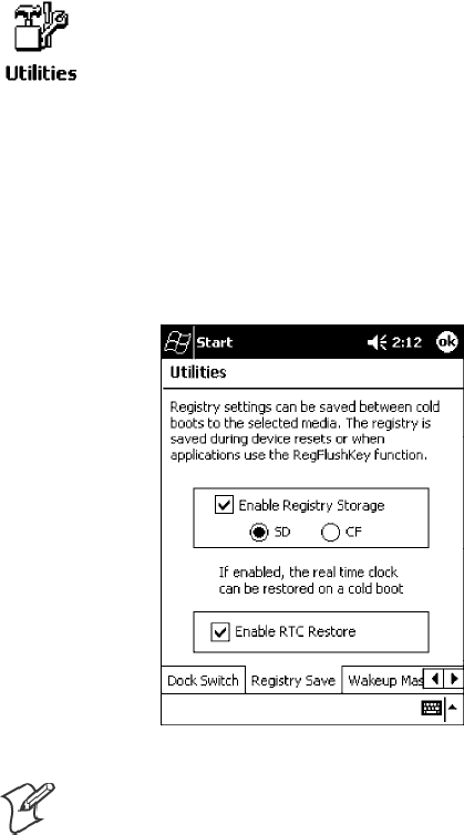
Installing Applications—Chapter 3
81700 Series Color Mobile Computer User’s Manual
4Click Install to install the AUTORUN files onto the storage card.
5Create a “\Cabfiles” folder on the storage card. Copy any CAB files that
are to be extracted on every startup into this folder.
6In the “\2577” directory, add your custom AUTOUSER.DAT file. See
the Recovery Help for more information on how to set up an
AUTOUSER.DAT file.
7If you are using the RegFlushKey() API, the application must use a spe-
cial API to make sure the registry is written to the appropriate card; or
you can use the Utilities control panel applet, as follows:
aFrom the 700 Series Computer, tap Start →Settings →the System
tab →the Utilities icon →the Registry Save tab.
bTap Enable Registry Storage, then tap either of the following:
SSD
To write the registry to the SecureDigital storage card.
SCF
To write the registry to the CompactFlash storage card.
cTap ok to save your entry and exit the Utilities control panel applet.
Note: If you are using a SecureDigital storage card, you must change any
disk access from “Storage Card” to “SDMMC Disk.”
8Remove the storage card from the desktop PC and install the card into
the 700 Series Color Computer.
9Perform a cold-boot on the 700 Series Color Computer. Files will
automatically install from the storage card upon reboot. Any calls to the
RegFlushKey() API will automatically write the registry to the
appropriate location.
Installing ApplicationsChapter —3
82 700 Series Color Mobile Computer User’s Manual
When converting a 700 Series Monochrome Computer application to run
on the 700 Series Color Computer, most APIs should work without chan-
ges. Below are a few exceptions:
SThe 700 Series Monochrome Computer used the “\Storage Card” folder
for nonvolatile storage. You may need to change the application to store
data in a volatile location or onto the “SDMMC Disk” if a SecureDigi-
tal storage card is present in the system.
SIf the application uses the RegFlushKey() API, it must first verify that
the proper media is available in the system and call the special API men-
tioned in Step 7 on the previous page.
SIf the application will be using the 700 Color switchable dock, use the
API to set the proper port on the dock before communications.
SSome WAN radio options have changed. Review the WAN radio section
to determine if any changes will be required in your application.
SThe arrow and tab keys are swapped from the way they were on the 700
Series Monochrome Computers. Keyboard remapping is available on
the 700 Series Color Computer if these keys need to be changed. See
page 79 for more details.
SNo special SDK is needed to compile applications for the Xscale proces-
sor. Targeting the SA1110 processor will create applications that run on
the 700 Series Color Computer.
Cabinet File Installation
CAB files (short for cabinet files) are like .ZIP files, plus they register DLLs,
create shortcuts, modify registry entries, and run custom set up programs.
Tap a CAB file to extract that file or place the CAB file on one of the ap-
proved storage devices in the “\Cab Files” folder, then perform a warm-
boot on the 700 Series Computer. There are two methods available to ex-
tract a CAB file:
STap a CAB file to extract it. When using this method, the CAB file is
automatically deleted when the extraction process is successful, unless
the CAB file is set with the read-only attribute.
SUse the AUTOCAB method where all files are extracted when a cold-
boot is performed on the 700 Series Computer. This AutoCab applica-
tion is on the Recovery CD, see its “Recovery Help” for more informa-
tion.

83700 Series Color Mobile Computer User’s Manual
Network Support
4
The 700 Series Color Mobile Computer can integrate up to three radios in
a single unit, and will automatically install the appropriate software for ra-
dio use when the unit is powered on. The Intermec CORE application
defaults to the most recently used module. If a module has not yet been
used or set, CORE will default to the first module as listed alphabetically.
The following communication options on the 700 Series Computer pro-
vide wired and wireless connectivity:
SOnboard wired Ethernet (standard)
SWireless Local Area Network (LAN)
This 802.11b radio option provides up to 11 Mb/sec throughput.
SWireless Wide Area Network (WAN)
Includes support for GSM/GPRS and CDMA/1xRTT radios.
SWireless Printing
This allows for cable-free communications with peripheral devices, such
as printers, over a ten-meter range. This compatibility is provided via a
Bluetooth qualified module by Socket Communications.
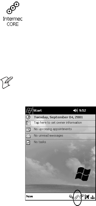
Network SupportChapter —4
84 700 Series Color Mobile Computer User’s Manual
CORE
The Intermec Common Object Resource Environment (CORE) applica-
tion provides a framework for various modules that let you configure and
manage your Intermec products. These modules are software plug-ins that
can be configuration tools, such as the 802.11b radio configuration mod-
ule, or they can provide information on your environment, such as a bat-
tery life module.
CORE is built into the operating system of every 700 Series Computer.
On the 700 Series Computer, tap Start →Programs →the Intermec
CORE icon to access this application.
CORE modules are collections of specific information. This information is
usually related to a particular radio technology, but not always. Each
module can display general and detailed information. Tap the General and
Details tabs near the bottom to switch between general and detailed
information. Note that not all modules will have detailed information.
To learn more about this application, see its online help. Tap Start →
Help from the menu to see the CORE online help.
Note: Once CORE is running, you can return to it by tapping its icon
from the System Tray via the Today screen. Tap Start →Today →the
Intermec CORE three-ring icon (circled in the following illustration).

Network Support—Chapter 4
85700 Series Color Mobile Computer User’s Manual
Network Adapters
Your 700 Series Computer can have up to three radios installed. The de-
fault network adapter or radio is dependent on what card is inserted in
your 700 Computer. Below are the the network adapters that exist as of
this publication. See the Developer’s Support web site for the latest infor-
mation on network adapters for your unit.
Ethernet Communications (LAN9000) - page 86.
802.11b Radios (802.11b Wireless LAN driver) - page 87.
WWAN (Wireless WAN) - page 110.
Wireless Printing (PAN) - page 120.
Note that the tip of the antenna attached to your 700 Series Computer is
color-coded to identify its radio type. Refer to the following to determine
your radio type:
Green
802.11b diversity
Red
CDMA (non-Sprint networks)
White
GPRS US/Canada and CDMA Sprint networks
Blue
GPRS International
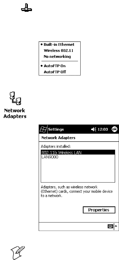
Network SupportChapter —4
86 700 Series Color Mobile Computer User’s Manual
Ethernet Communications
Follow the steps below to start Ethernet communications on the 700 Series
Computer. If your system does not contain an 802.11b radio, then
Ethernet networking using DHCP will be selected as the default.
When “Built-in Ethernet” is selected from the NDISTRY pop-up menu,
then the antenna shown to the left will appear in the System Tray. When
“No networking” is selected, then this icon will appear with a red “X”
above it.
From the 700 Series Computer, tap Start →Settings →the Connections
tab →Network Adapters to access the network connections for this unit.
Make the changes necessary for your network, then tap ok when finished.
Note: “LAN9000” is for Ethernet and ”802.11b Wireless LAN” is for
802.11b radios.
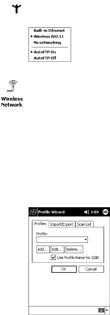
Network Support—Chapter 4
87700 Series Color Mobile Computer User’s Manual
802.11b Communications
The 700 Series Computer can integrate the 802.11b radio module along
with either the GSM/GPRS or the CDMA/1xRTT radio and the Wireless
Printing option. The 802.11b radio module accommodates any Wireless
LAN (WLAN) requirements, such as using WLAN access points for cross-
docking or load-planning applications.
When “Wireless 802.11” is selected via the NDISTRY pop-up menu, then
the antenna shown to the left will appear in the System Tray.
To start 802.11b communications on the 700 Series Computer, tap Start
→Settings →the System tab →the Wireless Network icon to access the
Profile Wizard for the 802.11b radio module. The Profile Wizard defaults
to the Profiles page.
Profiles
Use the Profiles page to add, edit, or delete multiple networking environ-
ments for this 802.11b radio. To add a profile from this screen, enter up to
32 alphanumeric characters in the Profile field, then tap Add.See“Basic”
on page 89 and “Security” on page 90 for more information.
Leave Use Profile Name for SSID checked for the SSID (or Network
Name) to use this profile name. If this is cleared (check mark removed),
the SSID will default to using the factory-assigned “INTERMEC” net-
work name.
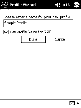
Network SupportChapter —4
88 700 Series Color Mobile Computer User’s Manual
STo add a profile:
Tap Add, enter up to 32 alphanumeric characters to name this profile if
you have not already entered a description in the Profiles page, configu-
re the basic and security information for this profile, then click Done to
configure its basic and security information.
SLeave Use Profile Name for SSID checked for the SSID to use this as-
signed profile name. If this is cleared (check mark removed), the SSID
will default to using the factory-assigned “INTERMEC” network name.
Go to the next page to continue.
STo edit a profile:
Select an existing profile from the Profile drop-down list, tap Edit,
make the changes needed for this profile (starting in the next para-
graph), then tap OK to return to the Profiles page.
STo delete a profile:
Select a profile from the Profile drop-down list, tap Delete,thentapYes
to remove the selected profile.
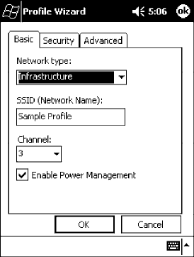
Network Support—Chapter 4
89700 Series Color Mobile Computer User’s Manual
Basic
Use the Basic page to set the network type and radio channel for this pro-
file. Click OK to return to the Profiles page.
SNetwork type:
Tap the drop-down list to select either Infrastructure or Ad-hoc.
SSSID (Network Name):
This assumes the profile name when Use Profile Name for SSID is
checked on the previous screen, unless another name is entered in this
field. If you want to connect to the next available network or are not
familiar with the network name, enter “ANY” in this field. Consult your
LAN administrator for network names.
SChannel:
If “Ad-hoc” were selected as the network type, then this is enabled. Tap
the drop-down list to select a channel, from 1-15, through which to
handle connections (default is 3).
SEnable Power Management:
Check this box to conserve battery power (default), or clear this box to
disable this feature.
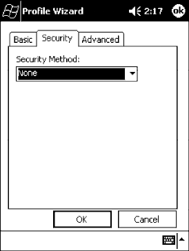
Network SupportChapter —4
90 700 Series Color Mobile Computer User’s Manual
Security
Use the Security page to set this profile as read-only or to enable WEP
(Wired Equivalent Privacy) encryption. Click OK to return to the Profiles
page. The following securities are available from the Security Method
drop-down list. Note that the last three methods are available if you have pur-
chased the security package. Contact your Intermec Representative for more in-
formation.
S802.11 WEP Encryption (next page)
S802.1x TLS (page 92)
S802.1x TTLS (page 93)
SLEAP (page 93)
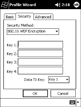
Network Support—Chapter 4
91700 Series Color Mobile Computer User’s Manual
802.11 WEP Encryption:
WEP keys are only needed if they are expected by your clients. There are
two types available: 64-bit (5-character strings, 12345) (default) and
128-bit (13-character strings, 1234567890123). These can be entered as
either ASCII (12345) or Hex (0x3132333435).
To enter WEP keys, select “802.11 WEP Encryption” from the Security
Method drop-down list. Select a data transmission key from the Data TX
Key drop-down list near the bottom of this screen, then enter the encryp-
tion key for that data transmission in the appropriate Key # field.
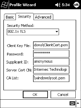
Network SupportChapter —4
92 700 Series Color Mobile Computer User’s Manual
802.1x TLS (Transport Layer Security):
TLS is a protocol that ensures privacy between communicating applica-
tions and their users on the Internet. To use this protocol, select “802.1x
TLS” from the Security Method drop-down list, then enter the following:
SClient Key File:
Enter the file location where the certificate for your identity is stored.
SPassword:
Enter the password for the certificate in this field.
SSupplicant ID:
Enter the user ID associated with this certificate.
SServer Cert CN (Certificate Common Name):
Enter the common name of your authentication server.
SCA List (Certificate Authority):
Enter the file location, or path, of the server certificates.
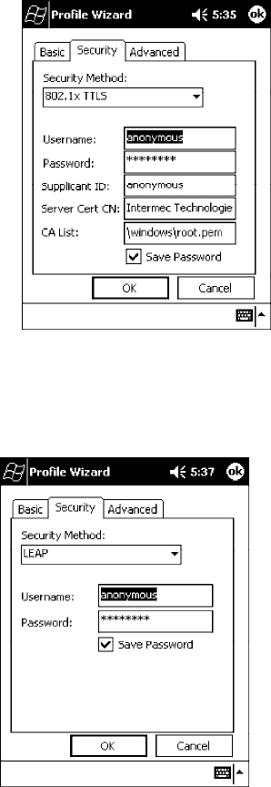
Network Support—Chapter 4
93700 Series Color Mobile Computer User’s Manual
802.1x TTLS (EAP-Tunneled TLS):
To use this protocol, select “802.1x TTLS” from the Security Method
drop-down list, then enter the following:
SUsername:
Enter your user name for this security protocol.
SPassword:
Enter your password for this security protocol.
SSupplicant ID:
Enter “anonymous” unless your administrator indicates otherwise.
SServer Cert CN (Certificate Common Name):
Enter the common name of your authentication server.
SCA List:
Enter the file location, or path, of the server certificates.
LEAP (Cisco Wireless EAP (Extensible Authentication Protocol)):
Enter your unique user name and password to use this protocol.
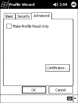
Network SupportChapter —4
94 700 Series Color Mobile Computer User’s Manual
Advanced
Use this page to secure the configuration for this profile or to make all
fields read-only.
SMake Profile Read-Only:
Check this box, then enter and reenter a password to “lock” or render
“read-only” all configurations for this profile. To reverse this step, clear
the check box, then enter the password assigned with the “read-only”
status.
SCertificates:
If “802.1x TLS,” “802.1x TTLS,” or “LEAP” were enabled via the Se-
curity tab, then this button will appear. Tap this button to configure the
available certificates. See “Certificates” on the next page for more infor-
mation.
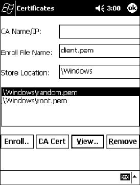
Network Support—Chapter 4
95700 Series Color Mobile Computer User’s Manual
Certificates
Use this page to view, modify, or remove certificates assigned to your
particular security method. Note that you can also access this page by tapping
Start →certificates from the Today screen.
SCA Name/IP:
Enter a valid CA name or IP address assigned to the certificate in ques-
tion. This allows you to enroll the certificate or to browse for its latest
information.
SEnroll File Name:
Enter the file name of the certificate to be enrolled.
SStore Location:
Enter the path where the certificate is to be stored within your 700 Se-
ries Computer.
SEnroll:
Tap this to assign the file entered in Enroll File Name to the location
specified in Store Location.
SCA Vert:
Tap this to view the contents of the certificate via the Internet Explorer.
SView:
Tap this to view information about the certificate, such as to whom this
certificate was issued, who issued the certificate, and the span of time
the certificate is valid.
SRemove:
Select a file from the list, then tap this button to delete that file.
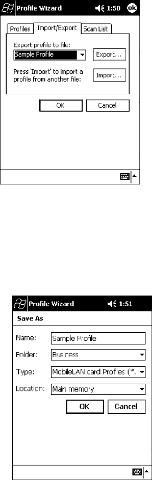
Network SupportChapter —4
96 700 Series Color Mobile Computer User’s Manual
Import/Export
Use this page to send a profile or to retrieve a profile to or from another
location within your 700 Series Computer.
STo export a profile:
Select to highlight a profile, then tap Export. Select from the drop-down
lists, the folder, type of files, and location within the folder where the
profile is to go, tap OK to export the profile, tap ok to close the con-
firmation screen, then tap OK again to exit the Profile Wizard.
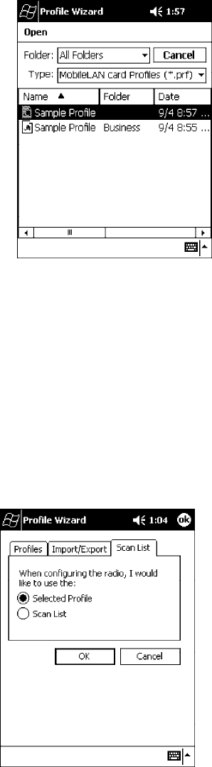
Network Support—Chapter 4
97700 Series Color Mobile Computer User’s Manual
STo import a profile:
Tap Import to access the Open screen, from the drop-down lists, select a
folder and file type, then tap a profile from the list provided. Tap ok to
close the confirmation screen, then tap OK again to exit the Profile
Wizard.
Scan List
Use this Scan List page to monitor network connections, and if lost, to at-
tempt to reestablish connections with these networks.
Selected Profile
Select this option to use the profile defined in the Profiles page, then tap
OK to exit the Profile Wizard. When connections are lost, attempts will be
made to connect to the specified profile.
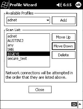
Network SupportChapter —4
98 700 Series Color Mobile Computer User’s Manual
Scan List
Use this option to select a number of profiles with which to establish con-
nections. When connections are lost, attempts will be made to contact each
of the profiles listed, in the order they appear in the list.
1Tap this option, then tap Edit Scan List.
2Select profiles from the Available Profiles drop-down list, then tap Add
to include each selection in the Scan List.
3To arrange the hierarchy of profiles, tap to select a profile, then tap ei-
ther Move Up or Move Down to move each profile. To remove a pro-
file from the list, tap to select that profile, then tap Delete.
4Click either ok or Close to return to the Scan List page, then click OK
to exit the Profile Wizard.
Network Selection APIs
The Network Selection APIs allow the user to change network adapter
configuration programmatically. Both drivers support the same IOCTL
function numbers for loading and unloading the drivers.
Loading and unloading of the 802.11b driver is performed by the FWV1:
device in the system by performing DeviceIOControl() calls to the driver.
Loading and unloading of the driver for the built-in Ethernet adapter is
performed by the SYI1: device in the system by performing DeviceIO-
Control() calls to the driver.
SFor loading an NDIS driver associated with an adapter, the IOCTL is
IOCTL_LOAD_NDIS_MINIPORT.
SFor unloading NDIS drivers associated with an adapter the IOCTL is
IOCTL_UNLOAD_NDIS_MINIPORT.
Network Support—Chapter 4
99700 Series Color Mobile Computer User’s Manual
#include <winioctl.h>
#include “sysio.h”
void DoLoad(int nDevice) {
LPTSTR devs[] = { _T(“SYI1:”), _T(“FWV1:”) };
HANDLE hLoaderDev;
DWORD bytesReturned;
hLoaderDev = CreateFile(devs[nDevice], GENERIC_READ|GENERIC_WRITE, 0,
NULL, OPEN_EXISTING, 0, NULL);
if (hLoaderDev != INVALID_HANDLE_VALUE) {
if (!DeviceIoControl( hLoaderDev, IOCTL_LOAD_NDIS_MINIPORT, NULL, -1, NULL, 0,
&bytesReturned, NULL)){
MessageBox(NULL, TEXT(“SYSIO IoControl Failed”), TEXT(“Network
loader”),MB_ICONHAND);
if (hLoaderDev!=INVALID_HANDLE_VALUE) CloseHandle(hLoaderDev);
hLoaderDev = INVALID_HANDLE_VALUE; // bad handle
}else {
CloseHandle(hLoaderDev);
}
}
}
void DoUnload(int nDevice) {
LPTSTR devs[] = { _T(“SYI1:”), _T(“FWV1:”) };
HANDLE hLoaderDev;
DWORD bytesReturned;
hLoaderDev = CreateFile(devs[nDevice], GENERIC_READ|GENERIC_WRITE, 0,
NULL, OPEN_EXISTING, 0, NULL);
if (hLoaderDev != INVALID_HANDLE_VALUE) {
if (!DeviceIoControl( hLoaderDev, IOCTL_UNLOAD_NDIS_MINIPORT, NULL, -1, NULL, 0,
&bytesReturned, NULL)){
MessageBox(NULL, TEXT(“SYSIO IoControl Failed”),TEXT(“Network
loader”),MB_ICONHAND);
if (hLoaderDev!=INVALID_HANDLE_VALUE) CloseHandle(hLoaderDev);
hLoaderDev = INVALID_HANDLE_VALUE; // bad handle
}else {
CloseHandle(hLoaderDev);
}
}
}
Network SupportChapter —4
100 700 Series Color Mobile Computer User’s Manual
The API provided by Intermec Technologies exposes a limited set of rou-
tines that allows a programmer to access and affect the 802.11b network
interface card from within their application. The routines provided will
also read/write values to the CE registry that pertain to the 802.11b radio
driver. By using the provided functions, a programmer can alter the
802.11b parameters of Network Name (SSID), WEP Keys, Infrastructure
Modes, Radio Channel, and Power Management Modes. A programmer
can also retrieve network connect status and signal strength indication
from the RF network card.
The API is contained within the 80211API.DLL file that should be pres-
ent in any load that has the 802.11b networking installed.
SNETWLAN.DLL
This file is the 802.11b driver. It will be present in all 700 CE loads that
use the 802.11b network interface card.
S80211API.DLL
This file is an Intermec authored file that provides the programmer with
a set of API calls to configure or monitor status of the 802.11b network.
SMOD80211.DLL
The CORE module for the 802.11b NIC. It provides the 802.11b sta-
tus information displayed when the CORE application is running.
S80211CONF.EXE
This is the “Control Panel” for configuring the 802.11b network para-
meters. Note that it is an EXE file and is actually called by
CPL802.CPL (see below). It is also called by the CORE application
when the “Configuration” button is pressed.
SCPL802.CPL
A control panel application that does nothing but call
80211CONF.EXE.
S80211SCAN.EXE
Internally manages the Scan List activity.
The 80211API.DLL supports an unlimited number of radio configuration
profiles. These profiles are the same as those set by the Wireless Network
control panel applet that runs on the Windows CE unit. You can configure
different 802.11b profiles and switch between them using the 802.11 API.
See the ConfigureProfile() function on page 106 for more information.
Network Support—Chapter 4
101700 Series Color Mobile Computer User’s Manual
Function Summary
Below are functions available for the 700 Series Color Computer when
enabled with the 802.11b radio module.
RadioConnect()
Connects to the available radio. Use this function if you plan on using a
lot of API calls that talk directly to the radio.
Syntax: UINT RadioConnect( );
Parameters: None.
Returns: ERROR_SUCCESS when successful, otherwise
ERR_CONNECT_FAILED.
RadioDisconnect()
Cleans up the connection from the RadioConnect() function after an ap-
plication closes.
Syntax: UINT RadioDisconnect( );
Parameters: None.
Returns: ERROR_SUCCESS when successful, otherwise
ERR_CONNECT_FAILED.
GetMac()
Gets the radio MAC address.
Syntax: UINT GetMac( TCHAR * );
Parameters: Pointer to a character array, which is populated with MAC addresses.
Returns: ERROR_SUCCESS when successful,
ERR_QUERY_FAILED when the query failed, or
ERR_CONNECT_FAILED if a connection with the radio failed.
GetBSSID()
Gets the associated access point name, the BSSID.
Syntax: UINT GetBSSID( TCHAR * );
Parameters: Pointer to a character array, which is populated with the current BSSID.
Returns: ERROR_SUCCESS when successful,
ERR_QUERY_FAILED when the query failed, or
ERR_CONNECT_FAILED if a connection with the radio failed
GetSSID()
Gets the current SSID (network name).
Syntax: UINT GetSSID( TCHAR * );
Parameters: Pointer to a character array, which is populated with the current SSID.
Returns: ERROR_SUCCESS when successful,
ERR_QUERY_FAILED when the query failed, or
ERR_CONNECT_FAILED if a connection with the radio failed.
Network SupportChapter —4
102 700 Series Color Mobile Computer User’s Manual
GetLinkSpeed()
Retrieves the current link speed of the radio connection.
Syntax: UINT GetLinkSpeed( int &);
Parameters: &References an integer.
Returns: ERROR_SUCCESS when successful,
ERR_QUERY_FAILED when the query failed, or
ERR_CONNECT_FAILED if a connection with the radio failed.
GetNetworkType()
Retrieves the network type.
Syntax: UINT GetNetworkType( ULONG &);
Parameters: &References a ULONG value, populated with one of the following:
NDIS_NET_TYPE_FH Frequency Hopping Radio
NDIS_NET_TYPE_DS Direct Sequence Radio
NDIS_NET_TYPE_UNDEFINED
Unknown or information not available.
Returns: ERROR_SUCCESS when successful,
ERR_QUERY_FAILED when the query failed, or
ERR_CONNECT_FAILED if a connection with the radio failed.
GetTXPower()
Gets the current TX power of the radio in milliwatts.
Syntax: UINT GetTXPower( ULONG &);
Parameters: &References a ULONG value, populated with one of the following
in milliwatts (mW):
NDIS_POWER_LEVEL_63 63 mW.
NDIS_POWER_LEVEL_30 30 mW.
NDIS_POWER_LEVEL_15 15 mW.
NDIS_POWER_LEVEL_5 5mW.
NDIS_POWER_LEVEL_1 1mW.
NDIS_POWER_LEVEL_UNKNOWN
Unknown Value or Error.
Returns: ERROR_SUCCESS when successful,
ERR_QUERY_FAILED when the query failed, or
ERR_CONNECT_FAILED if a connection with the radio failed.
Network Support—Chapter 4
103700 Series Color Mobile Computer User’s Manual
GetNetworkMode()
Retrieves the network mode.
Syntax: UINT GetNetworkMode( ULONG &);
Parameters: &References a ULONG value, populated with one of the following:
NDIS_NET_MODE_IBSS 802.11 Ad-Hoc Mode.
NDIS_NET_MODE_ESS 802.11 Infrastructure Mode.
NDIS_NET_MODE_UNKNOWN Unknown Value or Error.
NDIS_NET_AUTO_UNKNOWN
Automatic Selection. Use of this option is not recommended.
Returns: ERROR_SUCCESS when successful,
ERR_QUERY_FAILED when the query failed, or
ERR_CONNECT_FAILED if a connection with the radio failed.
SetNetworkMode()
Sets the radio and updates the CE registry.
Syntax: UINT SetNetworkMode( ULONG &);
Parameters: &References a ULONG value, populated with one of the values defined
in GetNetworkMode().
Returns: ERROR_SUCCESS when successful,
ERR_QUERY_FAILED when the query failed, or
ERR_CONNECT_FAILED if a connection with the radio failed.
AddWep()
Adds a WEP key to the radio configuration.
Syntax: UINT AddWep( ULONG 1, BOOL 2, TCHAR * 3);
Parameters: ULONG Pointer that identifies what key to be set.
BOOL Specifies whether the key being set is the default TX key.
TCHAR Pointer that specifies the key data either in hex (string
lengths of 10 or 26) or ASCII (string lengths of 5 or 13).
Returns: ERROR_SUCCESS when successful,
ERR_QUERY_FAILED when the query failed, or
ERR_CONNECT_FAILED if a connection with the radio failed.
GetRSSI()
Sets the current RSSI (Received Signal Strength Indication).
Syntax: UINT GetRSSI( ULONG & );
Parameters: &References a ULONG value.
Returns: ERROR_SUCCESS when successful,
ERR_QUERY_FAILED when the query failed, or
ERR_CONNECT_FAILED if a connection with the radio failed.
Network SupportChapter —4
104 700 Series Color Mobile Computer User’s Manual
GetAssociationStatus()
Gets the current connection, or association status.
Syntax: UINT GetAssociationStatus( ULONG &);
Parameters: &References a ULONG value, a current connection status as follows:
NDIS_RADIO_ASSOCIATED Radio is associated w/access point.
NDIS_RADIO_SCANNING Radio is scanning for network.
Returns: ERROR_SUCCESS when successful,
ERR_QUERY_FAILED when the query failed, or
ERR_CONNECT_FAILED if a connection with the radio failed.
GetWepStatus()
Gets the current WEP status.
Syntax: UINT GetWepStatus( ULONG &);
Parameters: &References a ULONG status value which include the following:
NDIS_RADIO_WEP_ENABLED WEP is currently enabled.
NDIS_RADIO_WEP_DISABLED WEP is currently disabled.
NDIS_RADIO_WEP_ABSENT WEP key is absent.
NDIS_RADIO_WEP_NOT_SUPPORTED
WEP is not supported.
Returns: ERROR_SUCCESS when successful,
ERR_QUERY_FAILED when the query failed, or
ERR_CONNECT_FAILED if a connection with the radio failed.
GetAuthenticationMode()
Gets the current authentication mode.
Syntax: UINT GetAuthenticationMode( ULONG &);
Parameters: &References a ULONG value which include the following current
authentication mode:
NDIS_RADIO_AUTH_MODE_OPEN Open System is in use.
NDIS_RADIO_AUTH_MODE_SHARED Shared Key is in use.
NDIS_RADIO_AUTH_MODE_AUTO Automatic Detection.
NDIS_RADIO_AUTH_MODE_ERROR Unknown value/Error.
Returns: ERROR_SUCCESS when successful,
ERR_QUERY_FAILED when the query failed, or
ERR_CONNECT_FAILED if a connection with the radio failed.
SetAuthenticationMode()
Sets the radio authentication mode with a value defined in the
GetAuthenticationMode() function.
Syntax: UINT SetAuthenticationMode( ULONG );
Parameters: Passes in a ULONG set to one of the values as defined in
GetAuthenticationMode().
Returns: ERROR_SUCCESS when successful,
ERR_QUERY_FAILED when the query failed, or
ERR_CONNECT_FAILED if a connection with the radio failed.
Network Support—Chapter 4
105700 Series Color Mobile Computer User’s Manual
SetChannel()
Sets the radio channel, ranging from 1 to 14.
Syntax: UINT SetChannel( USHORT );
Parameters: USHORT set to a desired channel (1-14).
Returns: ERROR_SUCCESS when successful,
ERR_QUERY_FAILED when the query failed, or
ERR_CONNECT_FAILED if a connection with the radio failed.
EnableWep()
Enables or disables WEP encryption.
Syntax: UINT EnableWep( BOOL );
Parameters: Set to TRUE (0) to enable WEP encryption or FALSE (1) to disabled
WEP encryption.
Returns: ERROR_SUCCESS when successful,
ERR_QUERY_FAILED when the query failed, or
ERR_CONNECT_FAILED if a connection with the radio failed.
GetPowerMode()
Gets the current power management mode of the radio.
Syntax: UINT GetPowerMode( ULONG &);
Parameters: &References a ULONG value which include the following current radio
power management mode:
NDIS_RADIO_POWER_MODE_CAM
Continuous Access Mode (uses most power).
NDIS_RADIO_POWER_MODE_MAX
Maximum Power Savings.
NDIS_RADIO_POWER_MODE_PSP
Power Saving Mode, best balance of power and performance.
NDIS_RADIO_POWER_UNKNOWN
Unknown mode reported or error.
Returns: ERROR_SUCCESS when successful,
ERR_QUERY_FAILED when the query failed, or
ERR_CONNECT_FAILED if a connection with the radio failed.
SetSSID()
Passes the desired SSID (network name).
Syntax: UINT SetSSID( TCHAR * );
Parameters: Pointer to a character array that contains the desired SSID.
Returns: ERROR_SUCCESS when successful,
ERR_QUERY_FAILED when the query failed, or
ERR_CONNECT_FAILED if a connection with the radio failed.
Network SupportChapter —4
106 700 Series Color Mobile Computer User’s Manual
isOrinoco()
Confirms whether the present radio is an ORiNOCO radio.
Syntax: UINT isOrinoco( );
Parameters: None.
Returns: TRUE when an ORiNOCO radio.
FALSE when other than an ORiNOCO radio.
EncryptWepKeyForRegistry()
Encrypts a key for registry storage. Requires TCHAR pointers for a des-
tination and a source.
Syntax: UINT EncryptWepKeyForRegistry( TCHAR * szDest, TCHAR *
szSource );
Parameters: szDest String for the destination.
szSource String for the source.
Returns: ERROR_SUCCESS when successful,
ERR_QUERY_FAILED when the query failed, or
ERR_CONNECT_FAILED if a connection with the radio failed.
SetRTSThreshold()
Sets the radio RTS (Request To Send) threshold.
Syntax: UINT SetRTSThreshold( USHORT &);
Parameters: &References a USHORT value.
Returns: None.
GetRTSThreshold()
Gets the radio RTS threshold.
Syntax: UINT GetRTSThreshold( USHORT &);
Parameters: &References a USHORT value.
Returns: None.
ConfigureProfile()
If using the Intermec 802.11b Profile Management system, you can pro-
gram the API to configure the radio to a specific profile by passing the pro-
file name.
Syntax: UINT ConfigureProfile( TCHAR * );
Parameters: Pointer to a string that contains the name of the profile to be activated.
Returns: None.
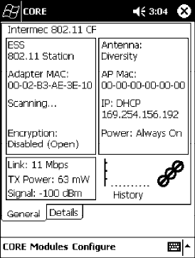
Network Support—Chapter 4
107700 Series Color Mobile Computer User’s Manual
StartScanList()
If a scan list is configured, this will start the API looking for a network on
that scan list and configuring the radio appropriately. This call can take a
long time to process.
Syntax: UINT StartScanList( );
Parameters: None.
Returns: None.
802.11b Radio CORE Module
The 802.11b radio CORE module displays helpful information about the
802.11b radio option built into your 700 Series Computer.
Note that you can configure the 802.11b radio module from this CORE
application. Select Configure →Configure 802.11 CF from the bottom
menu bar to access the Profile Wizard application. Information about this
application starts on page 87.
Select Modules →Intermec 802.11 CF Help for more information on
the contents of this CORE module.
General
Below are descriptions and meanings for each piece of information pro-
vided via the General tab, reading from top to bottom starting on the left.
SESS 802.11 Station:
This identifies the type of network to which you are attached, either an
ESS (Embedded Security Subsystem) Station, or Ad-hoc.
SAdapter MAC:
This identifies the MAC address for this 802.11b adapter.
SScanning:
Status of association. When connected to a network, this changes to
“Connected to NET” with NET being the name of the network to
which you are connected.

Network SupportChapter —4
108 700 Series Color Mobile Computer User’s Manual
SEncryption:
This indicates whether WEP encryption is “Enabled” or “Disabled
(Open).” See page 90 for more information.
SLink:
This indicates the speed at which a connection is made.
STX Power:
This shows the speed (in milliwatts) at which transmissions are made.
SSignal:
This identifies the radio signal strength (in dBm).
SAntenna:
This identifies the antenna being used with the assigned profile.
SAP Mac:
This identifies the MAC address of the access point to which this 700
Series Computer is connected.
SIP:
This provides the IP address which can be set as either DHCP (Dynam-
ic Host Configuration Protocol) or statically.
SPower:
This indicates the power status of this 700 Series Computer: “Always
On” is the default.
SHistory:
This bar graph displays an active history of this radio module’ s quality
of connections.
SFriendly Indicator:
If the radio stack is loaded, then all three dots are filled. These dots are
left empty if the stack is not loaded. These dots do vary based on the
CORE application’ s perception of the overall connection quality.
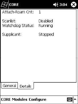
Network Support—Chapter 4
109700 Series Color Mobile Computer User’s Manual
Details
Below are descriptions and meanings for each piece of information pro-
vided via the Details tab, reading from top to bottom.
SAttach-Roam Cnt:
This includes the number of new associations made during the current
session, including any found roaming.
SScanlist:
This indicates whether the Scan List option was enabled or disabled. See
page 97 for more information.
SWatchdog Status:
This monitors the activity of the Scan List: “Running” or “Stopped.”
SSupplicant:
This monitors the 802.1x security activity on the client: “Running” or
“Stopped.”
Network SupportChapter —4
110 700 Series Color Mobile Computer User’s Manual
WWAN Radio Options
The 700 Series Computer can integrate either the GSM/GPRS or the
CDMA/1xRTT radio along with the 802.11b radio and the Wireless
Printing option. The WWAN radio option accommodates any Wireless
WAN requirements, such as taking the 700 Series Computer off the prem-
ises in a delivery vehicle to cover a much larger area.
GSM/GPRS
The GSM (Global System for Mobile communications) and GPRS (Gen-
eral Packet Radio Service) wireless infrastructure increases voice capacity,
enables personalized “user-aware” services, and creates networking efficien-
cies to help wireless service providers drive reduced operating costs.
SGSM is an open, nonproprietary system. One of its great strengths is
the international roaming capability. This provides seamless and same-
standardized same-number contactability world-wide. GSM satellite
roaming has extended service access to areas with unavailable terrestrial
coverage.
SGPRS is the high-speed data evolution of GSM. GPRS supports Inter-
net Protocol (IP), enabling access to Internet and intranet content and
applications from GPRS wireless devices. The anticipated data rate for
GPRS is 115 Kbps and throughput rates of 30-60 Kbps have been
achieved initially. This high speed capability enables vehicle applications
to become real-time and to use the Internet for access to corporate data
or information in the form of traffic or navigation.
CDMA/1xRTT SB555
Code Division Multiple Access (CDMA) is a form of “spread-spectrum,” a
family of digital communication techniques used in military applications
for years. The core principle of spread-spectrum is the use of noise-like
carrier waves, and, as the name implies, bandwidths much wider than that
required for simple point-to-point communication at the same data rate.
S1XRTT, the first phase of CDMA2000, is designed to support up to
144 KB per second packet data transmission and to double the voice
capacity of current generation CDMA networks.
SSB555 Embedded Module, from Sierra Wireless, provides complete
wireless functionality and integrates easily into the most compact and
slender mobile applications with its small flexible design. The SB555
offers maximum coverage and access to entire CDMA networks.
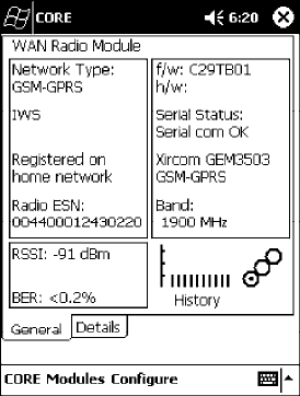
Network Support—Chapter 4
111700 Series Color Mobile Computer User’s Manual
WAN Radio CORE Module
The WAN radio CORE module displays helpful information about either
the GSM/GPRS radio or the CDMA/1xRTT radio option built into your
700 Series Computer. The following illustrations are for a GSM/GPRS
GEM350X radio.
General
Below are descriptions and meanings for each piece of information pro-
vided via the General tab, reading from top to bottom starting on the left.
The information applies to both the GSM/GPRS and the CDMA/1xRTT ra-
dio modules unless otherwise indicated.
SNetwork Type:
This is the network type which would list either “GSM-GPRS” or
“CDMA-1XRTT.” Scatternets are not supported.
SIWS (GSM/GPRS) or Sprint PCS Network (CDMA/1xRTT):
This lists the name of the wireless network provider, such as T-Mobile,
Voicestream, AT&T Wireless, etc. “IWS” is short for the Iowa Wireless
Service carrier.
SRegistered on home network:
If the WAN radio module has registered with a service provider net-
work, then one of the following will appear:
SRegistered on home network:
The radio module is registered on its “home” network.
SRegistered on roamed network:
The radio module is registered on another service provider’ s network.
SRadio Not Registered:
There is no network within range of this radio module.
SRadio ESN:
This displays the Electronic Serial Number (ESN) assigned to this radio
module or lists “Unavailable” if a number cannot be read from the ra-
dio.

Network SupportChapter —4
112 700 Series Color Mobile Computer User’s Manual
SRSSI:
This displays the Received Signal Strength Indicator (RSSI) frequency or
lists “Unavailable” if there is no signal or the signal cannot be retrieved
from the radio module.
SBER (GSM/GPRS GEM 350X, CDMA/1xRTT):
This shows the Bit Error Rate (BER), the percentage of bits with errors
divided by the total number of bits transmitted, received, or processed
over a given period of time.
Sf/w:
This identifies the firmware version, if available.
Sh/w:
This identifies the hardware version, if available.
SSerial Status:
This indicates whether serial communications passed (“Serial com OK”)
or failed (“Serial com FAIL”) in its last transaction. A status of “Serial
com FAIL” typically indicates that the 700 Series Computer is unable to
establish communication with the radio module installed within.
SXircom GEM3503 (GSM/GPRS),Siemens MC45 (GSM/GPRS),or
Sierra Wireless SB555 (CDMA/1xRTT):
This identifies the product name for this radio module.
SBand (GSM/GPRS) or Channel (CDMA/1xRTT):
This identifies the bandwidth or channel available for this radio module,
if any.
SHistory:
This bar graph displays an active history of this radio module’ s quality
of connections.
SFriendly Indicator:
Usually indicates the signal strength for this radio module. Three filled
dots indicate a high quality or strong signal. Three empty dots indicate
that the signal is out of range or there is no signal detected.
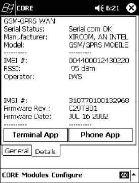
Network Support—Chapter 4
113700 Series Color Mobile Computer User’s Manual
Details
Below are descriptions and meanings for each piece of information pro-
vided via the Details tab, reading from top to bottom. Most of this is simi-
lar to what is shown under the General tab. The information applies to both
the GSM/GPRS and the CDMA/1xRTT radio modules unless otherwise indi-
cated.
SSerial Status:
This indicates whether serial communications passed (“PASS”) or failed
(“FAIL”) in its last transaction. A status of “FAIL” typically indicates
that the 700 Series Computer is unable to establish communication
with the radio module installed within.
SManufacturer:
This lists the name of the manufacturer that developed this radio mod-
ule, such as “Xircom, an Intel Corporation,” “Siemens,” or “Sierra Wire-
less.”
SModel:
This identifies the product name for this radio module, such as
“SB555,” “GEM350X,” or “MC45.”
SIMEI # (GSM/GPRS):
This is the IMEI (International Mobile station Equipment Identity) se-
rial number of the GSM/GPRS radio module.
SRSSI:
This displays the RSSI frequency or lists “Unavailable” if there is no sig-
nal or the signal cannot be retrieved from the radio module.
SOperator:
This lists the name of the service providing the network support.
SSIM Status (GSM/GPRS MC45):
Identifies whether a Subscriber Identity Module (SIM) card is installed
in this 700 Series Computer.
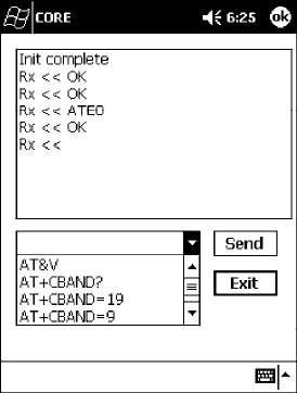
Network SupportChapter —4
114 700 Series Color Mobile Computer User’s Manual
SBand (CDMA/1xRTT):
This identifies the frequency bands used by this radio module.
SIMSI # (GSM/GPRS):
This shows the IMSI (International Mobile Subscriber Identity) number
assigned to the SIM card installed in this 700 Series Computer.
SRadio Temp (CDMA/1xRTT):
This identifies the temperature of the radio module, or lists “Unavail-
able degrees” if there is no information or the temperature cannot be
measured.
SFirmware Rev:
This identifies the firmware version, if available.
SFirmware Date (GSM/GPRS):
This provides the last date when this firmware was updated, if available.
Terminal Application
Tap Terminal App from the Details page to send standard AT commands.
Information about these AT commands are available under “AT Command
Interface” on page 115.
Select an AT command from the drop-down list, then tap Send. The re-
sults of each test appears in the text box. Tap Exit or ok to close this screen
and return to the Details page.
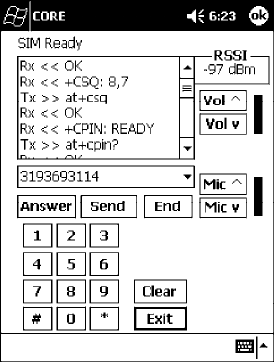
Network Support—Chapter 4
115700 Series Color Mobile Computer User’s Manual
Phone Application
With the WAN radio module installed in your 700 Series Computer, you
can send and receive telephone calls. Use the speaker on the back of the
computer as your earpiece and use the connector on the bottom of the
computer for your mouthpiece.
Tap Phone App from the Details page to access the application which will
process your phone calls. Tap Exit or ok to close this application and
return to the Details page.
STap the numbers for a phone call, using Clear to erase each digit, then
tap Send to initiate the call.
STap Answer to receive an incoming call.
STap End to disconnect a transaction.
STap Vol ^ or Vol v to adjust the speaker volume.
STap Mic ^ or Mic v to adjust the microphone sensitivity.
AT Command Interface
This interface specification is based on the following recommendation:
SETSI GSM 07.05:
European Digital Cellular Telecommunication System (phase 2)
Use of DTE-DCE interface for Short message and cell broadcast service.
SETSI GSM 07.07:
European Digital Cellular Telecommunication System (phase 2)
AT command set for GSM Mobile Equipment.
SITU-T Recommendation V.25 ter
Serial asynchronous automatic dialing and control.

Network SupportChapter —4
116 700 Series Color Mobile Computer User’s Manual
Note: You will need the Adobe Acrobat Reader application to view a PDF
document.Goto“http://www.adobe.com/prodindex/acrobat/readstep.html”
to install or download the latest Adobe Acrobat Reader according to
Adobe’ s instructions.
Command Set for Sierra Wireless SB555
Use the AT command interface from Sierra Wireless to program the
CDMA/1xRTT SB555 radio module. Documentation for this interface is
available via the following URL. Click the “General AT command refer-
ence” link for a PDF document, which is 680 KB in size. Note that this
URL is subject to change.
http://www.sierrawireless.com/ProductsOrdering/embedded_docs.html
Command Set for Xircom/Intel GEM350X
Use the GEM350X AT command list from Intel Corporation to program
the GPRS/GSM GEM350X radio module. The “GEM350X Programmer’ s
Reference” is available either from Intermec Technologies or from Intel
Corporation. Contact either your Intermec representative or the Intel Cor-
poration support personnel at the following URL for more information.
Note that this URL is subject to change.
http://support.intel.com/sites/support/index.htm?iid=intelhome1+support&
Command Set for Siemens MC45
Use the MC45 AT command interface from Siemens AG to program the
GPRS/GSM MC45 radio module. The “MC45 Siemens Cellular Engine
AT Command Set” is available either from Intermec Technologies or from
Siemens AG. Contact either your Intermec representative or the Siemens
AG support personnel at the following URL for more information. Note
that this URL is subject to change.
http://www.siemens-mobile.com/btob/CDA/presentation/ap_btob_cda_presentation_fron
tdoor/0,2950,12,FF.html
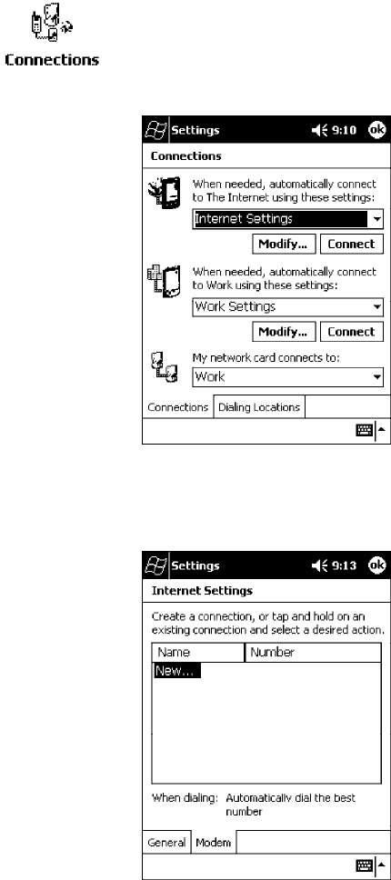
Network Support—Chapter 4
117700 Series Color Mobile Computer User’s Manual
Testing the AT Commands
These commands can be sent to either WAN radio by setting up a dial-up
networking connection to COM4. Do the following to initiate this con-
nection and test these commands to your radio:
1From the 700 Series Computer, select Start →Settings →the
Connections tab →the Connections icon.
2Tap Modify beneath the Internet Settings drop-down list.
3Tap New.. to make a new connection.
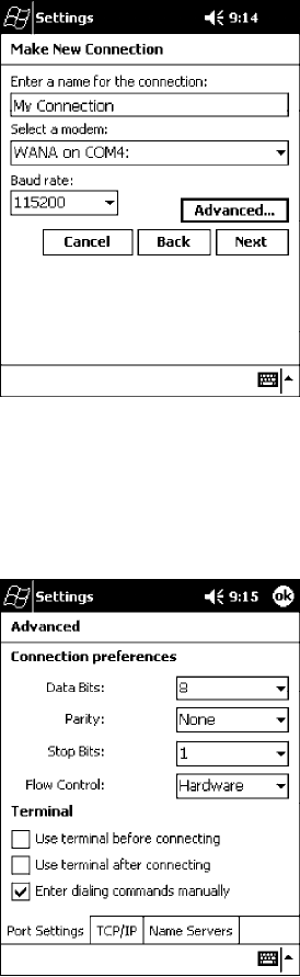
Network SupportChapter —4
118 700 Series Color Mobile Computer User’s Manual
4Enter a name for the connection, select “WANA on COM4” from the
Select a modem drop-down list, and select “115200” from the Baud
rate drop-down list. Tap Advanced to continue.
5On the Port Settings tab, check Enter dialing commands manually,
then tap ok,Next, then Finish to return to the Internet Settings screen
with your new connection.
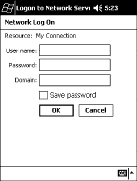
Network Support—Chapter 4
119700 Series Color Mobile Computer User’s Manual
6Press and hold the new connection for a pop-up menu, then tap
Connect to initiate the connection. Wait for about ten seconds for the
Network Log On screen, then tap OK.Note: You do not need to enter any
information within the Network Log On screen.
7Use either the onscreen keyboard, or press the keys to type any of the
AT commands provided by Sierra Wireless. Press or tap Enter to send
each command. The results of each command sent will print onscreen -
see the sample illustration below. Note that each “AT” command must
start with either the “at” or “at+” characters.
STo see what you typed onscreen, type “ate1” to initiate the AT Echo
command, then press Enter.
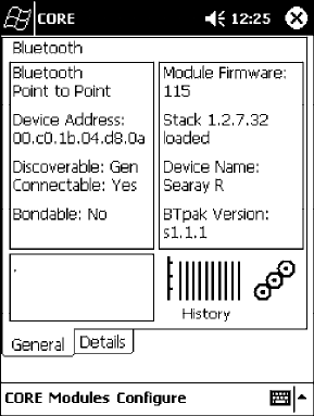
Network SupportChapter —4
120 700 Series Color Mobile Computer User’s Manual
Wireless Printing
The 700 Series Computer can integrate the Wireless Printing option
(which is equipped with a Bluetooth qualified module by Socket Communica-
tions) along with either the GSM/GPRS or the CDMA/1xRTT radio and
the 802.11b radio. This option uses the network to print information
stored on the 700 Series Computer.
“Bluetooth” is the name given to a technology standard using short-range
radio links, intended to replace the cables connecting portable and fixed
electronic devices. The standard defines a uniform structure for a wide
range of devices to communicate with each other, with minimal user ef-
fort. Its key features are robustness, low complexity, low power, and low
cost. The technology also offers wireless access to LANs, the mobile phone
network, and the internet for a host of home appliances and portable
hand-held interfaces.
Documentation
Information about additional “Bluetooth” software, including the Blue-
tooth Device Manager and the BTctrl program, can be found within the
Wireless Printing SDK. This is located on the 700C Software Tools CD,
via the directory off the root of the toolkit called “Wireless Printing SDK.”
It also can be found in the Wireless Printing Development Guide,alsoonthe
700C Tools CD.
Bluealps CORE Module
The Bluealps CORE module displays helpful information about this Wire-
less Printing option within your 700 Series Computer. Below are descrip-
tions and meanings for each piece of information provided via the General
tab, reading from top to bottom starting on the left.

Network Support—Chapter 4
121700 Series Color Mobile Computer User’s Manual
SBluetooth Point to Point:
This is the network type. “Point to Point” is the type of connection sup-
ported as of this publication. Scatternets are not supported. The only sup-
ported application is wireless printing to Intermec wireless printers, such
as the 781T Belt-Mount Printer.
SDevice Address:
This provides the network address, which in this case, will be replaced
by the device address of the Bluetooth compatible module within your
700 Series Computer. Note that this address is universally unique.
SDiscoverable:
The following is displayed depending on whether the 700 Series Com-
puter is configured to be discoverable:
“Gen” Generally discoverable
“Lim” Limited discovery
“No” Not discoverable
SConnectable:
This defines whether the 700 Series Computer is able to accept other
devices with Bluetooth compatible modules connecting to it. “Yes” if the
connection is doable, “No” if not.
SBondable:
This defines the security element of the 700 Series Computer, which is
the bondable setting. If the unit is bondable, then “Yes” is displayed,
otherwise “No” is displayed.
SModule Firmware:
This reflects the firmware (hardware) version of the 700 Series Comput-
er. When the CORE module first installs onto the unit, the firmware
level is unknown, thus “...reading” is displayed. Once the firmware level
is read from the unit, then a three-digit decimal is displayed.
SStack [Stack Version] [loaded/not loaded]:
[Stack Version] displays the Bluetooth stack version, which appears in the
“1.2.3.4” format. If the stack is loaded, then “loaded” is displayed after
the stack version, otherwise “not loaded” is displayed.
SDevice Name:
This displays the device name as assigned to the Bluetooth compatible
module by the end-user. If the configured name is longer than the space
allowed, it will be truncated.
SBTpak Version:
This displays the driver version of additional Bluetooth components
within the 700 Series Computer and is usually presented in the “1.2.3”
format. The version may also contain a letter at either end.
SHistory:
This bar graph displays an active history of this wireless printer driver’ s
quality of connections.
SFriendly Indicator:
If the Bluetooth stack is loaded, then all three dots are filled. These dots
are left empty if the stack is not loaded. These dots do vary based on the
CORE application’ s perception of the overall connection quality.

Network SupportChapter —4
122 700 Series Color Mobile Computer User’s Manual
AutoIP/DHCP
Automatic Private IP Addressing (AutoIP) is enabled by default in Pocket
PC 2002. To remain compatible with other Pocket PC devices, this setting
needs to be enabled. You can configure the registry settings in the
following to set the required AutoIP/DHCP behavior:
SFor Ethernet: HKEY_LOCAL_MACHINE\Comm\LAN9001\TcpIp
SFot 802.11b: HKEY_LOCAL_MACHINE\Comm\NETWLAN1\TcpIp
Other registry keys that can modify the behavior of AutoIP are as follows.
You can find the appropriate settings and behavior of each of these keys in
Microsoft Help.
SAutoInterval
SAutoMask
SAutoSubnet
SAutoIP
SAutoSeed
When a TCP/IP client cannot find a DHCP server, it generates an AutoIP
address from the 169.254.xxx.xxx block. The client then tries to check for
a DHCP server every 300 seconds (5 minutes) and if a DHCP server is
found, the client drops the AutoIP address and uses the address from the
DHCP server.
In the MSDN Windows CE documentation, see “Automatic Client Config-
uration” for more information on AutoIP.
To disable AutoIP, set the AutoCfg registry entry to “0.” If a DHCP server
cannot be found, instead of using AutoIP, the system will display the “Un-
able to obtain a server assigned IP address” message.
Note: If AutoIP is defined using CAB files, the EnableDHCP registry key
must also be defined and set to “1” before the system will attempt to ob-
tain a DHCP address.
To extend the number of attempts that a DHCP client makes to get a
DHCP address, use the DhcpRetryDialogue and DhcpMaxRetry registry
settings.
Change the AutoInterval registry key value to make the client retry more
often to obtain a DHCP address.
Network Support—Chapter 4
123700 Series Color Mobile Computer User’s Manual
SNMP Configuration
Simple Network Management Protocol (SNMP) was developed in the late
1980s to provide a general-purpose internetworking management protocol.
Its primary goal was to be simple so nothing would stand in the way of its
ubiquitous deployment. To this end, it has been very successful as it is cur-
rently deployed in almost every major internetworking product on the
market. However, like many achieved goals, the primary strength can also
become a weakness.
The Focus was “Simple”
An extreme example of simplicity versus power can be realized by compar-
ing SNMP against the Common Management Information Protocol
(CMIP), the ISO entry to the standard management protocol world.
CMIP has a very rich set of primitives and a core set of data elements.
However, to implement CMIP, a subset of the protocol must be selected.
Then, to achieve interoperability, this subset must be agreed upon with
other implementors. As SNMP was specified completely and with no op-
tions, one implemented what was there and interoperability was assured.
Returning to simplicity, SNMP was built simply for a number of reasons
other than time to market: robustness in the face of network failure, low
overhead in the devices running the protocol; and ease of debugging the
protocol itself (the last thing you want to debug is the management protocol
that is supposed to be helping you debug your network). Thus, the SNMP
limited itself to the User Datagram Protocol (UDP). This gave the
implementor the ability and responsibility to manage lost packets and
perform any necessary retransmissions. As network debugging in the face
of changing routes will certainly mean losing packets, retaining this control
from the transport service (layer 4) was considered essential. Since a
network management protocol will run continuously, it is mandatory that
it consume as minimal a network resource as possible. UDP allows the
necessary control over packet transmissions, packet size and content
(packetization). It is a natural choice.
Using SNMP
SNMP has three control primitives that initiate data flow from the
requester (get, get-next, and set). There are two control primitives the
responder uses to reply. One is used in response to the requester’ s direct
query (get-response) and the other is an asynchronous response to obtain
the requester’ s attention (trap). All five of these primitives are carried by
UDP and are thus limited in size by the amount of data that can fit into a
single UDP packet. The relatively small message size was a goal of the
design but for some reasonable set of network management functions, it
imposes a limitation.
Often in network management, it is necessary to obtain bulk information
without knowing at first what is in that bulk. In one case, there is a set of
problems having to do with packets not going where they are supposed to,
due to device misconfiguration that prevents proper protocol operation
where one needs to view the entire set of data.
Network SupportChapter —4
124 700 Series Color Mobile Computer User’s Manual
Retrieval of Management Information
SNMP has the get-next primitive which permits the viewing of data
without requiring prior knowledge. If you know what you are looking for,
the get primitive will return it. When you want an entire table of
information, the get-next primitive will obtain it. However, unless
employed with care, the get-next primitive can be extremely
resource-intensive in real time, network bandwidth, and the agent’ s CPU
time. The simplest use of the get-next primitive is to start at the beginning
of a table, await the response and then issue another get-next with the
name returned. As an example, say you wanted the next-hop address,
next-hop interface, and route-type from a routing table containing 1000
entries. Using the simplest form of get-next, this would require 2x3x1000
or 6000 packets (get-next and get-response packets, columns, and rows).A
straight-forward optimization would be to request the three columns in a
single packet. This puts the number of packets at 2x1000 or 2000 packets.
In real time, it is the product of the round trip by the number of request.
In agent CPU time, this is still 6000 lookups in the routing table for both
cases.
An Early Approach to Getting More than One Item at a Time
The ability to retrieve only one piece or object at a time has been a
problem for SNMP. This is particularly an issue with the use of this
protocol in wireless environments where the wireless datapipe is small and
overhead due to network management it is considered overhead. One
approach creates multiple get-next requests running concurrently. A second
algorithm, reduces the packet count by combining the multiple concurrent
get-nexts into a single packet. Neither approach has been implemented
which makes network management in wireless environment, though
essential to the success of the operation, tenuous. The issue has been
resolved in SNMP V2 protocol where a get-bulk primitive has been
defined.
Conclusion
Software development moves forward by evolving the unknown into the
known and wireless environments are moving from vertical only
application to wide spread implementation. At the time of the SNMP
inception, it was not possible to conceive of a reliable transport based
network management protocol. Today’ s problems require more
sophisticated data to analyze a problem. This puts the burden back on the
protocol to send and receive data quickly and efficiently. Work continues
in subcommittees to improve SNMP and resolve the issues that are
developing with new applications and new network architectures.

Network Support—Chapter 4
125700 Series Color Mobile Computer User’s Manual
SNMP Configuration on the 700 Series Computer
In short, SNMP is an application-layer protocol that facilitates the ex-
change of management information between network devices. The 700
Series Computer is such an SNMP-enabled device. Use SNMP to control
and configure the 700 Series Computer anywhere on an SNMP-enabled
network.
The 700 Series Computer supports four proprietary Management Infor-
mation Bases (MIBs) and Intermec Technologies provides SNMP support
for MIB-II through seven read-only MIB-II (RFC1213-MIB) Object
Identifiers (OIDs).
Note: You can only query these seven OIDs through an SNMP manage-
ment station, these are not available in the Unit Manager applications.
Management Information Base
The Management Information Base is a database that contains information
about the elements to be managed. The information identifies the manage-
ment element and specifies its type and access mode (Read-Only, Read-
Write). MIBs are written in ASN.1 (Abstract Syntax Notation.1) - a ma-
chine independent data definition language. Note: Elements to be managed
are represented by objects. The MIB is a structured collection of such objects.
You will find the following MIB files either on the 700C Tools CD or on
the web via http://www.intermec.com:
SINTERMEC.MIB
Defines the root of the Intermec MIB tree.
SITCADC.MIB
Defines objects for Automated Data Collection (ADC), such as bar code
symbologies.
SITCSNMP.MIB
Defines objects for Intermec SNMP parameters and security methods,
such as an SNMP security IP address.
SITCTERMINAL.MIB
Defines objects for 700 Series parameters, such as key clicks.

Network SupportChapter —4
126 700 Series Color Mobile Computer User’s Manual
Object Identifiers
Each object has a unique identifier called an OID. OIDs consist of a se-
quence of integer values represented in dot notation. Objects are stored in
a tree structure. OIDs are assigned based on the position of the object in
the tree. Seven MIB OIDs are shown in the followig table.
Example
The internet OID = 1.3.6.1.
MIB Object Identifiers
MIB-II Item OID Group or Table Description
ifNumber 1.3.6.1.2.1.2.1.0 Interfaces Group Indicates the number of adapters
present in the system. For the 700
Series Computer, if one adapter is
present in the system, then ifNum-
ber =1andifIndex=1.
ifIndex 1.3.6.1.2.1.2.2.1.1.ifIndex In te rf ac es Tabl e (i fTa bl e) A unique value for each interface.
The value ranges between 1 and the
value of ifNumber.
ifDescr 1.3.6.1.2.1.2.2.1.2.ifIndex Interfaces Table (ifTable) A textual string containing informa-
tion about the interface.
ifType 1.3.6.1.2.1.2.2.1.3.ifIndex In terfaces Tabl e (i fTa ble) An integer containing information
about the type of the interface. It is
equal to 1 for Other.
ipAdEntAddr 1.3.6.1.2.1.4.20.1.1.IpAddress IP address Table
(ipAddrTable)
The IP address to which this entry’ s
addressing information pertains
(same as 700 IP address), where IP
Address is the valid non-zero IP ad-
dress of the 700 Series Computer.
ipAdEntIfIndex 1.3.6.1.2.1.4.20.1.2.IpAddress IP address Table
(ipAddrTable)
The index value that uniquely iden-
tifies the interface to which this
entry is applicable (same as ifIndex).
ipAdEntNetMask 1.3.6.1.2.1.4.20.1.3.IpAddress IP address Table
(ipAddrTable)
The subnet mask associated with
the IP address of this entry (same as
Subnet Mask).
Configuring with SNMP
The community string allows an SNMP manager to manage the 700 Series
Computer with a specified privilege level. The default read-only communi-
ty string is “public” and “private” is the default read/write community
string. See the specific configuration parameter to find its OID. To config-
ure the 700 Series Computers using SNMP:
1Configure 700 Series Computers for RF or Ethernet communications.
2Determine the OID (Object Identifier) for the parameter to be chan-
ged. The Intermec base OID is 1.3.6.1.4.1.1963.
3Use your SNMP management station to get and set variables that are
defined in the Intermec MIBs. You can set the traps, identification, or
security configuration parameters for SNMP. See Appendix A, “Control
Panel Applets,” to learn more about these parameters.

127700 Series Color Mobile Computer User’s Manual
Printer Support
5
The 700 Series Color Mobile Computer works with the following printers
from Intermec Technologies. Contact an Intermec Representative for in-
formation about these printers.
S6820
A full-page, 80-column printer.
S6808
A 4-inch belt-mount printer.
S781T
A 2-inch belt-mount printer with a Bluetooth compatible module from
Socket Communications.
S782T
A 2-inch workboard printer.
Printer SupportChapter —5
128 700 Series Color Mobile Computer User’s Manual
Printing ASCII
The following methods for printing using Pocket PC at this time is as fol-
lows:
SAdd port drivers to print ASCII directly to the port.
SUse LinePrinter ActiveX Control from the Software Developer’ s Kit
(SDK) - see the SDK User’ s Manual for more information.
SVia wireless printing - see the Wireless Printing Development Guide on the
700C Software Tools CD for more information.
Directly to a Port
Printing directly to the port sends RAW data to the printer. The format of
this data depends upon your application and the printer capabilities.
You must understand the printer commands available for your specific
printer. Generally, applications just send raw ASCII text to the printer.
Since you are sending data to the printer from your application directly to
the port you are in complete control of the printers operations. This allows
you to do line printing (print one line at a time) rather than the page for-
mat printing offered by the GDI approach. It is also much faster since data
does not have to be converted from one graphics format to the other (dis-
play to printer). Most Intermecprinters use Epson Escape Sequences to
control print format operations.
These commands are available in documentation you receive with your
printers or from technical support. Win32 APIs are required to print di-
rectly to the port.
Directly to a Generic Serial Port
To print directly to a generic serial port printer (non-Intermec printers):
SUse CreateFile() to open ports - COM1: can be opened on most de-
vices.
SUse WriteFile() to send data directly to the printer.
SUse CloseHandle() when you are finished printing to close the port.
IrDA Printer Driver
IrDA printing is only available on the certain devices and is supported di-
rectly by the Windows CE load via the IrSock API provided by the Micro-
soft Win32 API without need for additional drivers. Intermec 6804, 6805,
6806, 6808 and 6820 and other IrDA printers are supported.
Printer Support—Chapter 5
129700 Series Color Mobile Computer User’s Manual
NPCP Printer Driver
The NPCP printer communications driver (NPCPPORT.DLL) is a
Stream Device Driver built into the operating system. The driver supports
only NPCP communications to and from the 6820 and 4820 printers over
a selected serial port.
All applications use WIN32 API functions to access the drivers. Basic op-
erations are easily implemented by applications through the CreateFile(),
WriteFile(), ReadFile(), DeviceIOControl(), and CloseHandle() Win32
APIs.
Operations to upgrade printer modules, perform printer diagnostics, and
get printer configuration are performed largely via DeviceIOControl()
functions.
About NPCP
NPCP (NorandPortable Communications Protocol) is a proprietary pro-
tocol that provides session, network, and datalink services for Intermec
mobile computers in the Intermec LAN environment used with printers
and data communications.
NPCP Driver Installation and Removal
Use LPT9: for the NPCP printer device and COM1 for the last parameter.
COM1 is the connection available via the 700 Series Computer.
Applications use the RegisterDevice() function to install the driver.
DeregisterDevice() uninstalls the device driver and frees memory space
when the driver is not required. Use the HANDLE returned by
RegisterDevice() as the parameter to DeregisterDevice().
Use the RegisterDevice() function call as demonstrated below. Specify the
full path name to the driver starting at the root for the RegisterDevice()
function to work properly. The last parameter to RegisterDevice() is a
DWORD that represents the name of the port for the NPCP stream driver
to use. Build this parameter on the stack if it is not to be paged out during
the call. The first parameter “LPT” (Device Name) and the second
parameter “9’ (index), indicate the name of the registered device, such as
LPT9. This is used in the CreateFile() function call.
Install()
{
HANDLE hDevice;
TCHAR port[6];
port[0] = TCHAR(‘C’);
port[1] = TCHAR(‘O’);
port[2] = TCHAR(‘M’);
port[3] = TCHAR(‘1’);
port[4] = TCHAR(‘:’);
port[5] = TCHAR(0);
hDevice = RegisterDevice ( (TEXT(”LPT”), 9,
TEXT(“\\STORAGE CARD\\WINDOWS\\NPCPPORT.dll”), (DWORD)port);
}
Printer SupportChapter —5
130 700 Series Color Mobile Computer User’s Manual
Opening the NPCP Driver
The application opens the NPCP driver by using the CreateFile()
function. The call can be implemented as follows. The first parameter
“LPT9:” must reflect the device name and index used in the
RegisterDevice() function call and will fail for any of the following reasons:
hFile = CreateFile(_T(”LPT9:”), GENERIC_WRITE |
GENERIC_READ, 0, NULL, OPEN_ALWAYS, FILE_ATTRIBUTE_NORMAL,
NULL);
SThe port associated with the device during RegisterDevice() is in use.
SThe NPCP device is already open.
SThe share mode is not set to zero. The device cannot be shared.
SAccess permissions are not set to GENERIC_WRITE |
GENERIC_READ. Both modes must be specified.
Closing the NPCP Driver
Using the CloseHandle() (hFile) function closes the NPCP driver. Where
hFile is the handle returned by the CreateFile() function call.
STRUE = the device is successfully closed.
SFALSE = an attempt to close NULL HANDLE or an already closed de-
vice.
Reading from the NPCP Driver
Reading of the NPCP printers is not supported since all responses from the
printer are the result of commands sent to the printer. DeviceIoControl()
functions are provided where data is to be received from the printer.
Writing to the NPCP Driver
All Print data can be sent to the printer using the WriteFile() function.
The print data written to the driver must contain the proper printer
commands for formatting. If the function returns FALSE, the NPCP error
may be retrieved using IOCTL_NPCP_ERROR. See the description on
the next page.
Printer Support—Chapter 5
131700 Series Color Mobile Computer User’s Manual
NPCP Driver I/O Controls
An application uses the DeviceIoControl() function to specify an printer
operation to be performed. Certain I/O controls are required to bind and
close communication sessions with the printer, and must be completed
before any other commands to the driver can execute properly.
The function returns TRUE to indicate the device successfully completed
its specified I/O control operation, otherwise it returns FALSE. The
following I/O control codes are defined:
#define IOCTL_NPCP_CANCEL
CTL_CODE(FILE_DEVICE_SERIAL_PORT,0x400,METHOD_BUFFERED,FILE_ANY_ACCESS)
#define IOCTL_NPCP_BIND
CTL_CODE(FILE_DEVICE_SERIAL_PORT,0x401,METHOD_BUFFERED,FILE_ANY_ACCESS)
#define IOCTL_NPCP_CLOSE
CTL_CODE(FILE_DEVICE_SERIAL_PORT,0x402,METHOD_BUFFERED,FILE_ANY_ACCESS)
#define IOCTL_NPCP_ERROR
CTL_CODE(FILE_DEVICE_SERIAL_PORT,0x403,METHOD_BUFFERED,FILE_ANY_ACCESS)
#define IOCTL_NPCP_FLUSH
CTL_CODE(FILE_DEVICE_SERIAL_PORT,0x404,METHOD_BUFFERED,FILE_ANY_ACCESS)
#define IOCTL_NPCP_IOCTL
CTL_CODE(FILE_DEVICE_SERIAL_PORT,0x405,METHOD_BUFFERED,FILE_ANY_ACCESS)
#define IOCTL_NPCP_PRTVER
CTL_CODE(FILE_DEVICE_SERIAL_PORT,0x406,METHOD_BUFFERED,FILE_ANY_ACCESS)
SIOCTL_NPCP_CANCEL
This cancels all printing at the printer. It flushes the printer buffers and
reinitializes the printer to its default state. No parameters are required.
SIOCTL_NPCP_BIND
This command is required before any data is sent or received by the
printer. Once the driver is opened, the application must bind the com-
munications session with the printer before any data can be sent or re-
ceived by the printer. If an error occurs during the bind, the application
may use IOCTL_NPCP_ERROR to get the current extended error
code. No parameters are required.
SIOCTL_NPCP_CLOSE
This command closes the current session with the printer. This function
always returns TRUE. No parameters are required.
SIOCTL_NPCP_ERROR
This command returns the extended NPCP error code in PL/N format.
The word returned will contain the PL/N compatible error code in the
low byte and completion flags in the high byte. If the frame that re-
turned an error was not received correctly by the printer the
FRAME_NOT_ACKED bit will be set in the high byte. This operation
always returns TRUE. An output buffer of at least 2 bytes is required.
See “NPCP Error Codes” on page 133.
SIOCTL_NPCP_FLUSH
This command allows the application to poll the printer for errors while
the report is completing the print process at the printer. If an error oc-
curs during the polling process, the operation will return FALSE and the
application can get the extended error code by using
IOCTL_NPCP_ERROR. No parameters are required.
Printer SupportChapter —5
132 700 Series Color Mobile Computer User’s Manual
NPCP Printer Communications
All NPCP printer communications should be based on the following flow:
1Use CreateFile(); to open the printer driver.
2Use IOCTL_NPCP_BIND to bind a session with the printer;
IOCTL_NPCP_ERROR to check for errors on the bind to ensure suc-
cess; and IOCTL_NPCP_CANCEL to cancel any outstanding print
jobs.
3Use IOCTL_NPCP_FLUSH to poll the printer to free up printer buff-
er resources. Use IOCTL_NPCP_FLUSH to poll the printer’ s status. If
an error is reported by the IOCTL, then use IOCTL_NPCP_ERROR
to get the error and determine the correct recovery procedure.
4Use WriteFile(); to write your data to the printer. Check for errors and
that all data were written. Use IOCTL_NPCP_ERROR to get the ex-
tended error. If the error is critical in nature, use
IOCTL_NPCP_CLOSE, followed by CloseFile(), to end the commu-
nications session. Start a new session, beginning with step 1 to ensure
proper printing. For noncritical errors display the error and retry the
operation.
5After all data is sent to the printer, ensure that the printer continues to
print the report properly by polling the printer’ s status. Use
IOCTL_NPCP_FLUSH to poll the printer’ s status. If an error is re-
ported by the IOCTL, then use IOCTL_NPCP_ERROR to get the er-
ror and determine the correct recovery procedure.
Sample Code
See sample code in the “\700 Color Dev Tools\Installable Drivers\Port
Drivers\Npcp\NPCPPrint\” directory for more details on printing, printer
communications and error code handling.
Printer Support—Chapter 5
133700 Series Color Mobile Computer User’s Manual
NPCP Error Codes
Call the IOCTL_NPCP_ERROR I/O control function to receive PL/N
compatible error codes. Applications must decide how to act upon the data
returned.
// Definition of NPCP communications Errors and Printer Errors
#define PNRDY (BYTE)102 // link not ready error
#define RXTMO (BYTE)104 // link no receive error
#define TXTMO (BYTE)106 // link no transmit error
#define BADADR (BYTE)111 // frame address error
#define GAPERR (BYTE)112 // link gap error (timeout) in receive data
#define LSRPE (BYTE)113 // frame parity error on length field
#define IFTS (BYTE)120 // session layer - invalid frame this state
#define NS_NE_VR (BYTE)121 // session layer sequence error
#define NR_NE_VS (BYTE)122 // session layer sequence error
#define MAC_CRCERR (BYTE)124 // MAC CRC error
#define RLENERR (BYTE)123 // MAC too much data received
#define FRMERR (BYTE)200 // Frame Reject
#define FRMERR_IF (BYTE)201 // Frame Reject - Invalid Frame
#define FRMERR_NR (BYTE)202 // Frame Reject - NR Mismatch
#define FRMERR_NS (BYTE)203 // Frame Reject - NS Mismatch
#define NDMERR (BYTE)204 // Normal Disconnect mode error
#define BINDERR (BYTE)210 // bind error
#define IPLDUR (BYTE)221 // invalid presentation layer response
#define HEADJAM (BYTE)222 // printer head jam
#define PAPEROUT (BYTE)223 // printer paper out
#define LOWVOLTS (BYTE)224 // printer low voltage
#define HIVOLTS (BYTE)225 // printer over voltage
#define LOWBAT (BYTE)226 // printer low battery
#define COVEROFF (BYTE)227 // printer cover off error
#define HEADFAULT (BYTE)228 // printer head short or driver short error
#define PFFAULT (BYTE)229 // paper feed motor fault.
#define FRAME_NOT_ACKED 0x8000 // frame was not received by printer and need to
be resent.
Printer SupportChapter —5
134 700 Series Color Mobile Computer User’s Manual
O’Neil Printer Driver
The DTR printer communications driver is a Stream Device Driver
named ONEIL.DLL.
All applications use WIN32 API functions to access drivers. Basic
operations are easily implemented by applications through the CreateFile(),
WriteFile(), DeviceIOControl() and CloseHandle() Win32 APIs.
The driver supports communications to 6804DM, 6804T, 6805A, 6806,
6808, 681T, and 781 printers over a selected serial port.
DTR Driver Installation and Removal
Your application must install the device driver by using the RegisterDe-
vice() function. The driver name is ONEIL.DLL. We recommend that
you use “DTR” for the Device Name parameter, “1” for the Device Driver
index parameter, and use any of the following strings for the last parame-
ter:
SNULL (==0) Defaults to COM1 @ 9600
S“COM1” only COM port specified defaults to 9600
S“COM1:9600” sets to COM port and specified bit rate
S“COM1:19200” sets to COM port and specified bit rate
Use the HANDLE returned by RegisterDevice() as the parameter to
DeregisterDevice(). The correct usage of the RegisterDevice() function call
is demonstrated below. You may use DeregisterDevice() to uninstall the
driver.
Install()
{
HANDLE hDevice;
TCHAR port[6];
port[0] = TCHAR(‘C’);
port[1] = TCHAR(‘O’);
port[2] = TCHAR(‘M’);
port[3] = TCHAR(‘1’);
port[4] = TCHAR(‘:’);
port[5] = TCHAR(0);
hDevice = RegisterDevice ( (TEXT(”DTR”), 1, TEXT(”\\WINDOWS\\ONEIL.DLL”),
(DWORD)port);
}
Printer Support—Chapter 5
135700 Series Color Mobile Computer User’s Manual
Opening the DTR Driver
The application opens the DTR driver by using the CreateFile() function.
The call can be implemented as follows:
hFile = CreateFile(_T(”DTR1:”), GENERIC_WRITE, 0, NULL,
OPEN_ALWAYS, FILE_ATTRIBUTE_NORMAL, NULL);
The first parameter “DTR1:” must reflect the device name and index used
in the RegisterDevice() function call.
The function call will fail for any of the following reasons:
SThe port associated with the device during RegisterDevice() is currently
in use.
SThe DTR device is already open.
SThe share mode is not set to zero. The device cannot be shared.
SAccess permissions are not set to GENERIC_WRITE.
Closing the DTR Driver
Using the CloseHandle() (hFile) function closes the DTR driver. Where
hFile is the handle returned by the CreateFile() function call.
STRUE indicates the device is successfully closed.
SFALSE indicates an attempt to close a NULL HANDLE or an already
closed device.
Writing to the DTR Driver
You can use the WriteFile() function to send all Print data to the printer.
The print data being written must contain the proper formatting printer
commands.
DTR Printer Communications
All DTR printer communications should be based on the following flow:
1Use CreateFile(); to open the printer driver.
2Use WriteFile() to write your data to the printer. Check for errors and
that all data were written.
3Use CloseHandle() to close the driver.
Printer SupportChapter —5
136 700 Series Color Mobile Computer User’s Manual

137700 Series Color Mobile Computer User’s Manual
Scanner Support
6
The 700 Series Color Mobile Computer is available with imaging or laser
scanning technologies, including the following:
SAPS linear imager:
Reads 1D symbologies and PDF 417 bar codes. Linear imaging using
Vista Scanning technology reads low-contrast bar codes, laminated bar
codes, and bar codes displayed on CRT or TRT displays. This imaging
uses harmless LEDs for illumination and does not require any warning
labels. Vista Scanning is more reliable than lasers as it is a completely
solid state with no moving parts or oscillating mirrors.
S2D Imager:
This decodes several stacked 1D and 2D symbologies, including PDF
417 and Data Matrix without “painting.” It can also read 1D codes
from any orientation, for example the scan beam does not need to be
aligned perpendicular to the symbol in order to read it. Photography is a
secondary application; the lens in the device will favor bar code reading.
Photos are 640x480, 256 gray-scale.
S1D laser scanner:
Traditional laser scanner that decodes 1D bar codes.
SPDF 417 laser scanner:
Higher speed laser scanner that can read PDF 417 labels by “painting”
the label.

Scanner SupportChapter —6
138 700 Series Color Mobile Computer User’s Manual
Scanner Control and Data Transfer
Note: To use the methods described below, enable Data Collection func-
tionality on the 700 Computer using the bootloader configuration menu.
See Chapter 3, “Installing Applications” for more information.
The Data Server and associated software provide several ways to manipu-
late scanner control and data transfer between the scanner subsystem and
user applications:
SAutomatic Data Collection COM Interfaces:
These COM interfaces allow user applications to receive bar code data,
and configure and control the bar code reader engine.
SITCAxBarCodeReaderControl functions:
These ActiveX controls allow user applications to collect bar code data
from the scanner, to configure the scanner, and to configure audio and
visual notification when data arrives. For more information, see the
SDK User’ s Manual.
SITCAxReaderCommand functions:
Use these ActiveX controls to modify and retrieve configuration infor-
mation using the reader interface commands. For more information, see
the SDK User’ s Manual.
SScanning EasySet bar code labels:
You can use the EasySet bar code creation software from Intermec
Technologies Corporation to print configuration labels. Scan the labels
to change the scanner configuration and data transfer settings.
Automatic Data Collection COM Interfaces
Data collection configuration and functionality cannot be accessed by any
means (including control panel applets or remote management applications)
until after the 700 Series Computer has completed initialization, which
occurs during a warm- or cold-boot or after a firmware upgrade.
When initialization is complete, the green LED on the 700 Series Com-
puter stops flashing. Changes made to configuration settings remain after a
warm boot. After a cold-boot, all configuration settings are reset to their
defaults with the exception of scanner configurations, which remain except
for the Symbology Identifier transmission option or the Preamble and
Postamble strings. To reset all configuration settings to the factory defaults,
the S9C scanner firmware must be reloaded.
6 Scanner Support—Chapter
139700 Series Color Mobile Computer User’s Manual
The Automatic Data Collection (ADC) functions are accessed through
custom COM interfaces. These interfaces allow the application to receive
bar code data and configure and control the bar code reader engine. The
COM interfaces include the following functions:
SIADC (starting on page 151)
SIBarCodeReaderControl (starting on page 159)
SIS9CConfig (starting on page 172)
SIS9CConfig2 (starting on page 204)
SIS9CConfig3 (starting on page 216)
SIImage Interface (starting on page 221)
Multiple ADC COM Object Support
A 700 Series Computer may have multiple reader engines to decode differ-
ent types of ADC data. For example, a bar code reader engine decodes raw
bar code data and passes it to a bar code reader COM object. An RFID
reader engine decodes raw RFID tag data and passes it to an RFID tag
reader COM object.
ADC COM interfaces are implemented as in-process COM objects. An
instance of the ADC COM object creates a logical connection to access or
control the reader engine. Specifically, the IBarCodeReadConfig or IBar-
CodeReaderControl COM objects can manage the bar code scanner con-
figuration while the ADC COM object can gather data simultaneously.
These ADC COM objects or connections can be created in a single ap-
plication or multiple applications. Up to seven instances of a COM object
can be created for a reader engine. For more information, see “How to
Create and Use the ADC COM Interfaces”below.
For data collection features, ADC COM objects also provide for read
ahead and non-read ahead data access and grid data editing.
Scanner SupportChapter —6
140 700 Series Color Mobile Computer User’s Manual
How to Create and Use the ADC COM Interfaces
You can also use the Input Device Functions (starting on page 149) to
create and use the ADC COM interfaces.
1Create and initialize the in-process Bar Code Reader object using
ITCDeviceOpen() (see page 149). This function returns a COM
Interface pointer to the Bar Code Reader Object created by the
function.
2Set the data grid if data filtering is desired (default grid gives the applica-
tion all the data). Below is a sample code of how to set the grid to accept
Code 39 data that starts with the letter “A” and is not a reader com-
mand.
ITC_BARCODEREADER_GRID stBCGrid;
stBCGrid.stDIGrid.szDataMask = TEXT(”A%s”);
stBCGrid.stDDGrid.dwSymbologyMask = BARCODE_SYMBOLOGY_CODE39;
stBCGrid.dwDataSourceTypeMask = ITC_DATASOURCE_USERINPUT;
HRESULT hrStatus = pIBCControl->SetAttribute(
ITC_RDRATTR_GRID,
reinterpret_cast<BYTE *>(&stBCGrid),
sizeof(stBCGrid)
);
3Issue a read to accept the bar code data. The timestamp, symbology, and
data type are put into the ITC_BARCODE_DATA_DETAILS struc-
ture. Passing in a pointer to this structure is optional. The following
sample code uses an infinite timeout.
ITC_BARCODE_DATA_DETAILS stBCDetails;
BYTE rgbBCData[1024]; // Buffer used to accept the bar code data
DWORD dwBytesReceived; // Number of bytes in the return data.
HRESULT hrStatus = pIBCControl->Read(
rgbBCData,
sizeof(rgbBCData),
&dwBytesReceived,
& stBCDetails,
INFINITE
);
4Compile and link the application.
Read-Ahead Bar Code Data Access
The Bar Code Reader COM object delivers ADC data to the connection
in read-ahead mode. In this mode, the data is queued until a COM con-
nection is ready to read it. Read-ahead mode decouples reader device per-
formance from the application performance. That is, data is read as fast as
the user can scan it, independent of the connection processing load. No
data will be scanned until the first Read() function is posted.
6 Scanner Support—Chapter
141700 Series Color Mobile Computer User’s Manual
Grid Data Filtering
The virtual wedge retrieves scanned Automatic Data Collection (ADC)
data and sends it to the keypad driver so that the 700 Series Computer can
receive and interpret the data as keypad input. The data can be filtered so
that only data conforming to a certain text pattern or symbology will be
sent to an application. After the data is filtered, it can be edited by adding,
deleting, or rearranging portions of the text or by extracting portions of
text for further editing. To filter and edit data, you need to define the
virtual wedge grid parameters.
SGrid Processing:
Grid processing takes place in two steps:
SCompilation:
In which the user’ s grid expressions are checked for errors and
reduced to a binary form for faster matching. This is done whenever
the virtual wedge grid is set or changed by configuration software.
SMatching:
In which data is tested against the grids set in compilation. Matching
can be performed multiple times after a compilation. The AIM
symbology ID of the data being tested, including the enclosing angle
brackets, must be prepended to the incoming data.
Syntax
The basic syntax of each grid expression is:
<symID> filter-expression= > editing-expression
where:
SsymID
Is the AIM symbology ID (see the AIM Symbology ID Defaults table
starting on page 219).
Sfilterexpression
Is any character string that includes valid filter expression values (see
the “Filter Expression Values” table on the next page).
Sediting-expression
Is any character string that includes valid editing expression values (see
the “Editing Expression Values” table on page 144).

Scanner SupportChapter —6
142 700 Series Color Mobile Computer User’s Manual
Filter Expression Values
A filter-expression can be any string of text containing the operators listed
below.
Filter Expression Values
Operator Meaning Example
Any character string not containing
thespecialcharacters:.?[]{}or\
(period, question mark, left/right
brackets, left/right curly brackets, back-
slash).
Match the string literally. super20 matches super20
\c where c is any of the special char-
acters:.?[]{}or\
(period, question mark, left/right
brackets, left/right curly brackets, back-
slash)
Remove any special meaning of c. \* matches *
.(period) Any character. . matches x
^ (tarot) Anchor the match at the beginning
of the string.
^abc matches abc, but not aabc
$ (dollar sign) Anchor the match at the end of the
string.
abc$ matches abc but not abcc
? (question mark) Repeat the preceding expression zero
or one time.
aa? matches a or aa
*(asterisk) Repeat the preceding expression zero
or more times.
ab*c matches ac, abc, abbc, etc.
+(plussymbol) Repeat the preceding expression one
or more times.
ab+c matches abc, abbc, etc.
[characterclass] A series of nonrepeating characters
denoting a class.
[abcdefhijklmnopqrstuvwxyz] is the
class of all lowercase alphas.
[rangel`rangeh] A sequential range of nonrepeating
characters denoting a class.
[a-z]istheclassofalllowercaseal-
phas.
[^characterclass] Any character except those denoted
by a character class.
[^a-z] matches a numeric digit or a
punctuation mark.
[characterclass_tag] [:alnum:] - Alphanumeric characters
[:alpha:] - Alphabetic characters
[:blank:] - Tab and space
[:cntrl:] - Control characters
[:digit:] - Numeric characters
[:graph:] - All printable characters ex-
cept space
[:lower:] - Lowercase letters
[:print:] - All printable characters
[:punct:] - Punctuation
[:space:] - White space characters
[:upper:] - Uppercase letters
[:xdigit:] - Hexadecimal digits
[[:alpha:]]* matches Dynaction,
Selmer, or NewWonder but not Su-
per20
{num} Matches exactly num repetitions. a{3} matches only aaa
{min,} Matches at least num repetitions. a{3,} matches aaaa but not aa

6 Scanner Support—Chapter
143700 Series Color Mobile Computer User’s Manual
Filter Expression Values (continued)
ExampleMeaningOperator
{min,max} A repetition operator like + or *, ex-
cept the number of repetitions is spe-
cified by min and max.
[a-z]{1,3} matches a, ab, or aab, but
not aabc
(expr1)|(expr2) Matches expr1 or expr2.a|b matches a or b
(subexpression) Grouping operator to consolidate
terms into a subexpression, which
can override the order of evaluation.
The subexpression is available for lat-
er matching or editing by means of
\index,where\index is between 1-9
and refers to the index-th group in
the string, counting from left to
right. \0 refers to the whole expres-
sion.
Overriding evaluation order: (ab)*c
matches c, abc, ababc, etc.
Back-referencing: (aa)bb\1 matches
aabbaa.

Scanner SupportChapter —6
144 700 Series Color Mobile Computer User’s Manual
Editing Expression Values
This table lists the valid operators for editing expressions.
Operator Meaning Example
\index The index-th subexpression (reading left-right)
in the matched string. index must be between
0`9. \0 is the matched expression itself.
M([0-9]{6})= > \1 produces 270494 when
M270494 is scanned, stripping off the first
character.
&or\0 The matched expression itself. M[0-9]{6}= > \0-Conn and
M[0-9]{6}= > &-Conn
both produce
M270494-Conn
when M270494 is scanned.
\xhh A concise representation of the lower 256
characters in the Unicode set. When con-
verted, this is still a 16-bit value.
\x0d inserts a carriage return.
any character string Inserts any character string in the output
string.
See previous examples.
S<symID> is optional. If present, only data in the indicated symbology is
accepted.
SIf the entire expression is blank, all data is passed unchanged. If =>
editing-expression is omitted, then all data that passes through the filter is
returned unchanged. If = > editing expression is present, the data is trans-
formed by editing-expression.
SMultiple grid expressions can be compiled and are related in a logical
OR fashion. These are expressed as single grid expressions separated by
semicolons. When matching is attempted, the first grid expression from
left to right that achieves a match will cause the data to be accepted.
SAll pattern expressions and parsed data are in Unicode.
Grid Filter Example 1
This accepts a serial number in which the encoded number is a six-charac-
ter string beginning with M followed by six numeric characters.
SFilter
M[0-9]{6}
SEffect
When a bar code, such as M270494, is scanned, all data is passed.
Grid Filter Example 2
This formats a scanned Social Security number and forms it into an XML
element tagged “SSN”.
SFilter
([0-9]{3})([0-9]{2})([0-9]{4})= > <SSN > \1-\2-\3</SSN >
SEffect
A bar code, such as 123456789, is passed and reformatted to
<SSN > 123-45-6789</SSN >
6 Scanner Support—Chapter
145700 Series Color Mobile Computer User’s Manual
Grid Filter Example 3
This deletes the first three and last five characters of a 21-character Code
128 label and deletes the first two characters of a 10-character Interleaved
2 of 5 label.
SFilter
<]C > ...(.{13}).....= > \1; <]I > ..(........)= > \1
SEffect
If Code 128, AAA1234567890123BBBBB becomes 1234567890123
If Interleaved 2 of 5, AA12345678 becomes 12345678
Grid Filter Example 4
This inverts data such that the first alphabetic string (like a first name) and
second alphabetic string (like a last name) are reversed and separated by a
comma and a space.
SFilter
([[:alpha:]])+ ([[:alpha:]])+= > \2, \1
SEffect
When a bar code with the data “Dexter Gordon” is scanned, the data is
modified to read “Gordon, Dexter”.
ADC Connection
A 700 Series Computer can have both Bar Code and RFID reader engines
with each engine supporting multiple connections. Each connection allows
an application to access data or manage a configuration. An application
could have multiple connections.
// Get an instance of the ADC COM object that corresponds integrated scanner
IBarCodeReaderControl *pIBCControl;
// Pointer to the Bar Code Reader object
HRESULT hrStatus = ITCDeviceOpen( TEXT(”default”),
IID_IBarCodeReaderControl, ITC_DHDEVFLAG_READAHEAD,
(LPVOID *) &pIBCControl);
// If the ADC object was successfully created and initialized, accept bar
code data.
ITC_BARCODE_DATA_DETAILS stBCDetails;
stBCDetails.wStructSize = sizeof(stBCDetails);
BYTE rgbBCData[1024];
//Buffer used to accept the bar code data
DWORD dwBytesReceived;
// Number of bytes in the return data.
HRESULT hrStatus = pIBCControl->Read(
rgbBCData,
sizeof(rgbBCData),
&dwBytesReceived,
& stBCDetails,
INFINITE
);
Scanner SupportChapter —6
146 700 Series Color Mobile Computer User’s Manual
2D Imager Overview
The 700 Color optional integrated 2D Imager captures 640x480
256-grayscale images at 20 frames per second. The imager features can be
categorized into data collection features and image acquisition features as
follows:
Data Collection Features
The imager includes a decode engine capable of decoding 2D matrix
symbologies such as Data Matrix as well as the traditional 1D and stacked
symbologies (see the table on the next page for supported symbologies). The
application programming interfaces used to collect bar code data and con-
figure the imager are the same as those used for the laser scanner. This in-
cludes the keyboard wedge as well as the ADC COM interfaces and in-
cludes functionality such as data editing and data filtering. In addition, the
imager has the following configuration features (see “IS9CConfig3 Func-
tions” starting on page 216 for configuration details):
SAimer LED:
A small, rectangular-aiming LED is displayed periodically during the
image capture and decoding process. The initial duration (after scan but-
tons are pressed) of the aimer LED can be configured. This helps to select
the specific bar code to be scanned with multiple bar codes in the
image.
SScaled Illumination LED:
When the ambient light is not sufficient to decode the bar code, the red
illumination LEDs will be turned on to brighten the image. The inten-
sity of the illumination LEDs is scaled to brighten the image just
enough for decode. The reduces power consumption and the effect of
specular reflection.
SWindow size and position:
The default window size (640x480) can be reduced in size and posi-
tioned. This is useful in applications where multiple bar codes may be
present in the image and the specific bar code must be selected to be
read. For example, the window can be sized and positioned around the
aimer LED. The entire bar code must reside in the configured window
for a good decode.
Omni-directional scanning is a feature that does not require configuration.
1D and stacked symbologies as well as 2D matrix symbologies can be
scanned with the 700 Series Computer in any orientation. Thus, time is
not needed to orient the 700 horizontal as with laser scanners.

6 Scanner Support—Chapter
147700 Series Color Mobile Computer User’s Manual
The following table shows which bar code symbologies are supported ei-
ther by an imager or by a laser scanner.
Bar Code Symbology Imager Laser Scanner
Code 39 XX
Interleaved 2 of 5 X X
Standard 2 of 5 XX
Matrix 2 of 5 X
Code 128 XX
Code 93 X X
Codabar XX
MSI X
Plessey X
UPC X X
EAN/EAN 128 XX
Code 11 X
PDF 417 XX
Micro PDF 417 X
Telep en X
Data Matrix X
QR Code X
Image Acquisition Features
The integrated imager provides the following image acquisition features:
SReal-time and Still Image Acquisition:
This includes functions that start and stop image acquisition and read
acquired images.
SSignature Capture:
This allows the application to retrieve an image of the normalized signa-
ture. This means the image is always oriented as if the picture were tak-
en at right angles to the signature, at the same distance, and in the cen-
ter of the image no matter in what orientation the picture was taken.
Signature capture requires a PDF 417 or Code 128 bar code symbology
to be present in the image and requires the application to identify the
X,Y offsets relative to the center the bar code, the X,Y dimension of
image to be captured, and the aspect ratio of the bar code. Note the
units are in terms of the narrow element width of the bar code.
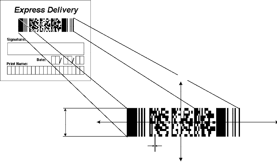
Scanner SupportChapter —6
148 700 Series Color Mobile Computer User’s Manual
See the following example signature capture label and dimensions. These
image acquisition features are provided through the IImage Interface
defined on page 221.
Y-axis
–Y
–X
Intelligent bar code
units
Bar code height
6 Scanner Support—Chapter
149700 Series Color Mobile Computer User’s Manual
Create and Delete ADC COM Object Functions
Use these functions to create and release ADC COM interfaces.
ITCDEVMGMT.H is the header file and ITCDEVMGMT.LIB is the
library.
ITCDeviceOpen
This function opens and initializes a communication channel to the de-
vice. In C++, this function returns a pointer to an interface on which the
methods are called. In C, this function returns a handle, which is the first
parameter in each of the interface function calls.
Syntax
HRESULT ITCDeviceOpen( LPCTSTR pszDeviceName, REFIID iid,
ITC_DEVICE_FLAGS eDeviceFlags, void** ppvObject );
Parameters
pszDevice [in] Pointer to a string that contains the device name
on which to initialize the logical connection.
The device name (Merlin 1) identifies a
communications port.
Use “default” for all internal scanners, such as
Imager, SE900, etc. Use “ExtScanner” for
tethered scanners.
iid [in] The identifier of the interface being requested.
eDeviceFlags [in] Enumeration that identifies the read
characteristics as follows:
SITC_DHDEVFLAG_READAHEAD
Data is buffered on behalf of the calling
applications. Data Buffering starts after the
first call to IADC::Read ().
SITC_DHDEVFLAG_NODATA
The client application is managing the device
to set its configuration or control its interface
but not to collect data from the device.
ppvObject [out] A pointer to the interface pointer identified by
iid. If the object does not support this interface,
ppvObject is set to NULL.
Return Values
HRESULT that indicates success or failure.
Remarks
None.
See Also
SITCDeviceClose
Scanner SupportChapter —6
150 700 Series Color Mobile Computer User’s Manual
ITCDeviceClose
This function closes the interface opened with ITCDeviceOpen.
Syntax:
HRESULT ITCDeviceClose( IUnknown** ppvObject );
Parameters
ppvObject [in,out] A pointer to the interface pointer created by
ITCDeviceOpen. If successful on output, this
pointer is set to NULL.
Return Values
None.
Remarks
On Windows, this interface decrements the reference count. So alterna-
tively, IUnknown::Release() could be used and must be used if reference
counting is performed with IUnknown::AddRef(). On DOS, this function
closes all resources associated with the channel.
See Also
None.
6 Scanner Support—Chapter
151700 Series Color Mobile Computer User’s Manual
IADC Functions
IADC functions provide ADC data in an input device independent man-
ner. This interface can receive bar code data, RFID data, and other ADC
data from data collection engines, such as a bar code scanner. Use IADC
functions if bar code specifics such as symbology are not important to the
application.
IADC functions are the following. IADC.H is the header file and
ITCUUID.LIB contains the IID_IADC Interface GUID value used to
obtain the interface.
SIADC::CancelReadRequest (page 152)
SIADC::Initialize (page 153)
SIADC::QueryAttribute (page 154)
SIADC::QueryData (page 155)
SIADC::Read (page 156)
SIADC::SetAttribute (page 157)
Scanner SupportChapter —6
152 700 Series Color Mobile Computer User’s Manual
IADC::CancelReadRequest
This function cancels a pending Read() request. This call can be made on a
separate thread as a Read() or on the same thread. On a separate thread,
the function is useful in unblocking a blocked Read() so that other opera-
tions can be performed. On the same thread, this function is useful in
stopping data from being collected on behalf of a Read Ahead Client.
Syntax
HRESULT IADC::CancelReadRequest( BOOL FlushBufferedData,WORD
*pwTotalDiscardedMessages, DWORD *pdwTotalDiscardedBytes );
Parameters
FlushBufferedData [in] True Flush and discard all already
buffered data.
False Do not discard data, data will be
returned on the next read call.
pwTotalDiscardedMessages [in/out] Total number of discarded buffered
labels or tags.
pdwTotalDiscardedBytes Total number of discarded bytes.
Return Values
HRESULT that indicates success or failure.
Remarks
The return value indicates whether a read was pending.
See Also
SIADC::Initialize
SIADC::QueryAttribute
SIADC::QueryData
SIADC::Read
SIADC::SetAttribute
6 Scanner Support—Chapter
153700 Series Color Mobile Computer User’s Manual
IADC::Initialize
This function initializes a connection by opening a communications chan-
nel with a logical reader engine. The communications port is implicitly
identified. This communication channel is required to collect data or con-
figure the device.
Syntax
HRESULT IADC::Initialize ( LPCTSTR pszDeviceName,
ITC_DEVICE_FLAGS eDeviceFlags );
Parameters
pszDeviceName [in] Pointer to a string that contains the device name
on which to initialize the logical connection.
The device name (Merlin 1) identifies a
communications port.
Use “default” for all internal scanners, such as
Imager, SE900, etc. Use “ExtScanner” for
tethered scanners.
eDeviceFlags [in] Enumeration that identifies the read
characteristic as follows:
SITC_DHDEVFLAG_READAHEAD
Data is buffered on behalf of the calling
application. Data buffering starts after the
first call to IADC::Read ().
Return Values
HRESULT that indicates success or failure.
Remarks
None.
See Also
SIADC::CancelReadRequest
SIADC::QueryAttribute
SIADC::QueryData
SIADC::Read
SIADC::SetAttribute
Scanner SupportChapter —6
154 700 Series Color Mobile Computer User’s Manual
IADC::QueryAttribute
This function retrieves a specified attribute that is device-independent.
The specified attribute can be a grid or multiclient enable status.
Syntax
HRESULT IADC::QueryAttribute (
ITC_ADC_ATTRIBUTE_ID eAttribID, BYTE rgbBuffer[], DWORD
dwBufferSize, DWORD *pnBufferData );
Parameters
eAttribID [in] Specifies the attribute. Only one attribute can be
queried at a time. See IADC::SetAttribute.
rgbBuffer [out] Contains buffer for the attribute to be queried.
The structure of lpBuffer depends on the
attribute being queried. See IADC::SetAttribute
for a description of these structures.
dwBufferSize [in] The maximum number of bytes rgbBuffer can
store.
pnBufferData [out] Pointer to the DWORD location to put the
number of bytes stored in rgbBuffer.
Return Values
HRESULT that indicates success or failure.
Remarks
None.
See Also
SIADC::CancelReadRequest
SIADC::Initialize
SIADC::QueryData
SIADC::Read
SIADC::SetAttribute
6 Scanner Support—Chapter
155700 Series Color Mobile Computer User’s Manual
IADC::QueryData
This function returns the status of user input data that has been buffered.
Syntax
HRESULT IADC::QueryData ( DWORD *dwTotalBufferedBytes, WORD
*wNumberOfMessages, DWORD *dwNextMessageSize );
Parameters
dwTotalBufferedBytes [out] Total bytes buffered for connection.
wNumberOfMessages [out] Total messages buffered. For example,
each buffer contains a single bar code scan.
dwNextMessageSize [out] Size (in bytes) of the next buffered
message.
Return Values
A standard status code that indicates success or failure.
Remarks
None.
See Also
SIADC::CancelReadRequest
SIADC::Initialize
SIADC::QueryAttribute
SIADC::Read
SIADC::SetAttribute
Scanner SupportChapter —6
156 700 Series Color Mobile Computer User’s Manual
IADC::Read
This function requests user input data from the reader engine. This is a
blocking function that returns either when there is data or after a timeout.
Syntax
HRESULT IADC::Read ( BYTE rgbDataBuffer[], DWORD
dwDataBufferSize, DWORD pnBytesReturned, SYSTEMTIME
pSystemTime, DWORD dwTimeout );
Parameters
rgbDataBuffer [in] Pointer to the buffer that receives the data
from the device.
dwDataBufferSize [in] Maximum number of bytes that can be
stored in rgbDataBuffer.
pnBytesReturned [out] Pointer to the DWORD location to store
the number of bytes returned in
rgbDataBuffer.
pSystemTime [out] Pointer to a SYSTEMTIME structure that
will hold the time stamp of the received
data. This can be NULL if a timestamp is
not needed.
dwTimeout [in] Number of milliseconds caller waits for
data. This parameter is ignored if the
Read Ahead flag is not set.
S0
If data is not available, returns quickly.
SINFINITE
Waits until data is available.
Return Values
HRESULT that indicates success or failure.
Remarks
None.
See Also
SIADC::CancelReadRequest
SIADC::Initialize
SIADC::QueryAttribute
SIADC::QueryData
SIADC::SetAttribute
6 Scanner Support—Chapter
157700 Series Color Mobile Computer User’s Manual
IADC::SetAttribute
This function changes an attribute such as a grid specification.
Syntax
HRESULT IADC::SetAttribute ( ITC_ADC_ATTRIBUTE_ID eAttribID,
BYTE rgbData[], DWORD nBufferSize );
Parameters
eAttribID [in] Identifies the attribute to set. Only one attribute
can be set at a time. The attribute is:
SITC_MULTICLIENT_ENABLE
Indicates whether this client can coexist with
other clients.
rgbData [in] Contains data for the attribute to be set.
Depending on the eAttribID, this will be mapped
to the appropriate structure as follows:
SITC_MULTICLIENT_ENABLE
BOOL is the rgbData Data Structure.
STRUE, Client can receive data with other
clients (default).
SFALSE, Data stream to this client is turned
off when there are other clients.
SITC_DHATTR_READFILTER
ITC_READFILTER is the rgbData Data
Structure. The ITC_READFILE structure is
defined in IADCDEVICE.H as follows:
typedef struct
{
#define ITC_MAXFILTER_CHARS 240
WORD nFilterChars;
TCHAR szFilter[ITC_MAXFILTER_CHARS];
} ITC_READFILTER;
where:
SITC_MAXFILTER_CHARS
Maximum number of characters in a filter
specification. Includes NULL termination.
SnFilterChars Number of characters in
pszDataMask.
SszFilter Data mask specification. See
“Grid Data Filtering.”
nBufferSize [in] Number of bytes in rgbData.
ITC_DHATTR_READFILTER
Regular expression that performs data filtering and data editing. See “Grid
Data Filtering” on page 141 for more information.
Return Values
A standard status code that indicates success or failure.
Remarks
None.
Scanner SupportChapter —6
158 700 Series Color Mobile Computer User’s Manual
See Also
SIADC::CancelReadRequest
SIADC::Initialize
SIADC::QueryAttribute
SIADC::QueryData
SIADC::Read
6 Scanner Support—Chapter
159700 Series Color Mobile Computer User’s Manual
IBarCodeReaderControl Functions
IBarCodeReaderControl functions provide functionality for bar code
collection and control only. These functions allow an application to:
STrigger the bar code laser scanner
SDisable the scanner
SReceive a bar code with details such as symbology scanned, data type
(Unicode, ASCII), and the time the data was received.
These functions include the following. IBARCODEREADER.H is the
header file and ITCUUID.LIB contains the IID_IADC Interface GUID
value used to obtain the interface.
SIBarCodeReaderControl::CancelReadRequest (page 160)
SIBarCodeReaderControl::ControlLED (page 161)
SIBarCodeReaderControl::Initialize (page 162)
SIBarCodeReaderControl::IssueBeep (page 163)
SIBarCodeReaderControl::QueryAttribute (page 164)
SIBarCodeReaderControl::Read (page 165)
SIBarCodeReaderControl::SetAttribute (page 167)
SIBarCodeReaderControl::TriggerScanner (page 171)
Scanner SupportChapter —6
160 700 Series Color Mobile Computer User’s Manual
IBarCodeReaderControl::CancelReadRequest
This function cancels a pending IBarCodeReaderControl::Read request. If
the read request is blocked, issue the CancelReadRequest from a separate
thread.
Syntax
HRESULT IBarCodeReaderControl::CancelReadRequest( BOOL
FlushBufferedData, WORD *pwTotalDiscardedMessages,WORD
*pwTotalDiscardedBytes );
Parameters
FlushBufferedData [in] TRUE Flushes and discards all buffered
data.
FALSE Does not discard data; data will
be returned on the next read
call.
pwTotalDiscardedMessages [in/out] Total number of discarded
buffered labels or tags.
pwTotalDiscardedBytes Total number of discarded
bytes.
Return Values
HRESULT that indicates success or failure.
Remarks
None.
See Also
SIBarCodeReaderControl::ControlLED
SIBarCodeReaderControl::Initialize
SIBarCodeReaderControl::IssueBeep
SIBarCodeReaderControl::QueryAttribute
SIBarCodeReaderControl::Read
SIBarCodeReaderControl::SetAttribute
SIBarCodeReaderControl::TriggerScanner
6 Scanner Support—Chapter
161700 Series Color Mobile Computer User’s Manual
IBarCodeReaderControl::ControlLED
This function controls LED illumination on a tethered scanner. The good
read LED and any valid LEDs will be turned on and off based on defined
parameters.
Syntax
HRESULT IBarCodeReaderControl::ControlLED(
ITC_BARCODE_LASER_LED_ID eLED, BOOL fLedOn );
Parameters
eLED [in] The specified LED identifier.
SITC_BARCODE_LASER_GOOD_READ_LED
Identifies the good read LED.
fLedOn [in] TRUE turns on the LED. FALSE turns off the LED.
Return Values
HRESULT that indicates success or failure.
Remarks
This function does not coordinate LED control with the scanner. If the
scanner LED control is enabled, function results will be unpredictable.
See Also
SIBarCodeReaderControl::CancelReadRequest
SIBarCodeReaderControl::Initialize
SIBarCodeReaderControl::IssueBeep
SIBarCodeReaderControl::QueryAttribute
SIBarCodeReaderControl::Read
SIBarCodeReaderControl::SetAttribute
SIBarCodeReaderControl::TriggerScanner
Scanner SupportChapter —6
162 700 Series Color Mobile Computer User’s Manual
IBarCodeReaderControl::Initialize
This function opens and initializes a communications channel with a log-
ical bar code reader engine.
Syntax
HRESULT IBarCodeReaderControl::Initialize ( LPCTSTR
pszDeviceName, ITC_DEVICE_FLAGS eDeviceFlags );
Parameters
pszDeviceName [in] Pointer to a string with device on which to
initialize the logical connection. The device
identifies a communications port. Use “default”
for all internal scanners, such as Imager, SE900,
etc. Use “ExtScanner” for tethered scanners.
eDeviceFlags [in] Enumeration that identifies the read
characteristic as follows:
SITC_DHDEVFLAG_READAHEAD
Data is buffered on behalf of the calling
applications. Data Buffering starts after the
first call to IADC::Read ().
Return Values
HRESULT that indicates success or failure.
Remarks
None.
See Also
SIBarCodeReaderControl::CancelReadRequest
SIBarCodeReaderControl::ControlLED
SIBarCodeReaderControl::IssueBeep
SIBarCodeReaderControl::QueryAttribute
SIBarCodeReaderControl::Read
SIBarCodeReaderControl::SetAttribute
SIBarCodeReaderControl::TriggerScanner
6 Scanner Support—Chapter
163700 Series Color Mobile Computer User’s Manual
IBarCodeReaderControl::IssueBeep
This function causes the reader engine to generate a high beep, a low beep,
or a custom beep. The high beep and low beep are preconfigured beep
tones and durations. The custom beep allows the client to specify the fre-
quency and duration. The volume is the current volume setting. Note this
is not implemented.
Syntax
HRESULT IBarCodeReaderControl::IssueBeep( ITC_BEEP_SPEC
rgBeepRequests[], DWORD dwNumberOfBeeps );
Parameters
rgBeepRequests [in] Array of ITC_BEEP_SPEC structures that
identifies the beep type. The beep structure
is:
typedef struct tagITCBeepSpec
{
ITC_BEEP_TYPE eBeepType; // Identifies the type of beep
// Following fields used only if the beep type is ITC_CUSTOM_BEEP.
WORD wPitch; // Frequency, in Hz, of the beep.
WORD wOnDuration; // Duration, in milliseconds, of Beep On.
WORD wOffDuration; // Duration, in milliseconds, of Beep Off
// Beep Off is used to separate individual beeps
} ITC_BEEP_SPEC;
typedef enum tagITCBeepType
{
ITC_LOW_BEEP, // Issue the default low beep.
ITC_HIGH_BEEP, // Issue the default high beep.
ITC_CUSTOM_BEEP, // Issue a custom beep.
} ITC_BEEP_TYPE;
dwNumberOfBeeps [in] Identifies the total number of beeps in
rgBeepRequests.
Return Values
E_NOTIMPL as this function is not implemented.
Remarks
None.
See Also
SIBarCodeReaderControl::CancelReadRequest
SIBarCodeReaderControl::ControlLED
SIBarCodeReaderControl::Initialize
SIBarCodeReaderControl::QueryAttribute
SIBarCodeReaderControl::Read
SIBarCodeReaderControl::SetAttribute
SIBarCodeReaderControl::TriggerScanner
Scanner SupportChapter —6
164 700 Series Color Mobile Computer User’s Manual
IBarCodeReaderControl::QueryAttribute
This function retrieves the device-specific grid, the scanner enable status,
and the LED control status for the current bar code reader engine.
Syntax
HRESULT IBarCodeReaderControl::QueryAttribute (
ITC_BARCODEREADER_ATTRIBUTE_ID eAttr, BYTE rgbAttrBuffer[],
DWORD dwAttrBufferSize );
Parameters
eAttr [in] Specifies the attribute. See
IBarCodeReaderControl::SetAttribute on
page 167 for the attributes.
rgbAttrBuffer [out] Contains buffer for the attribute to be
queried. The structure of rgbAttrBuffer
depends on the attribute being queried.
See IBarCodeReaderControl::SetAttritbute
for a description of these structures.
dwAttrBufferSize [in] The maximum number of bytes that
rgbAttrBuffer can store.
Return Values
A standard status code that indicates success or failure.
Remarks
The following attributes are not supported on the imager:
SITC_RDRATTR_TONE_ENABLE
SITC_RDRATTR_VOLUME_LEVEL
SITC_RDRATTR_TONE_FREQUENCY
SITC_RDRATTR_GOOD_READ_BEEPS_NUMBER
SITC_RDRATTR_GOOD_READ_BEEP_DURATION
See Also
SIBarCodeReaderControl::CancelReadRequest
SIBarCodeReaderControl::ControlLED
SIBarCodeReaderControl::Initialize
SIBarCodeReaderControl::IssueBeep
SIBarCodeReaderControl::Read
SIBarCodeReaderControl::SetAttribute
SIBarCodeReaderControl::TriggerScanner
6 Scanner Support—Chapter
165700 Series Color Mobile Computer User’s Manual
IBarCodeReaderControl::Read
This function reads data from the bar code input device. This method per-
forms the same function as IADC::Read () except that it provides addition-
al information about data received such as bar code symbology used, data
type, and time stamp of received data.
Syntax
HRESULT IBarCodeReaderControl::Read ( BYTE
rgbDataBuffer[],DWORD dwDataBufferSize, DWORD
pnBytesReturned,ITC_BARCODE_DATA_DETAILS
pBarCodeDataDetails, DWORD dwTimeout );
Parameters
rgbDataBuffer [in] Pointer to the buffer that receives data
from the device.
dwDataBufferSize [in] Maximum number of bytes that can be
stored in rgbDataBuffer.
pnBytesReturned [out] Pointer to the DWORD location that will
store the bytes returned in rgbDataBuffer.
pBarCodeDataDetails [in] Address of data structure in which to put
the data details. This may be NULL. The
ITC_BARCODE_DATA_DETAILS is:
typedef struct tagITCBarCodeDetails
{
WORD wStructSize,
ITC_BARCODE_SYMBOLOGY_ID eSymbology,
ITC_BARCODE_DATATYPE eDataType,
SYSTEMTIME stTimeStamp,
}ITC_BARCODE_DATA_DETAILS;
typedef enum tagBarCodeDataType
{
BARCODE_DATA_TYPE_UNKNOWN = 1,
BARCODE_DATA_TYPE_ASCII,
BARCODE_DATA_TYPE_UNICODE,
}ITC_BARCODE_DATATYPE;
where:
SwStructSize Size of structure. Used for versioning structure.
SeSymbology Symbology of the returned data.
SeDataType Identifies data types as ASCII, UNICODE, etc.
SstTimeStamp Timestamp of the received data.
SBARCODE_DATA_TYPE_UNKNOWN Data in unknown.
SBARCODE_DATA_TYPE_ASCII Data is ASCII.
SBARCODE_DATA_TYPE_UNICODE Data is UNICODE.
Scanner SupportChapter —6
166 700 Series Color Mobile Computer User’s Manual
dwTimeout [in] Number of milliseconds caller waits for
data. If you set a timeout, the call will be
blocked until data is received.
S0
If data not available, returns quickly.
SINFINITE
Waits until data is available.
Return Values
HRESULT that indicates success or failure.
Remarks
None.
See Also
SIBarCodeReaderControl::CancelReadRequest
SIBarCodeReaderControl::ControlLED
SIBarCodeReaderControl::Initialize
SIBarCodeReaderControl::IssueBeep
SIBarCodeReaderControl::QueryAttribute
SIBarCodeReaderControl::SetAttribute
SIBarCodeReaderControl::TriggerScanner
6 Scanner Support—Chapter
167700 Series Color Mobile Computer User’s Manual
IBarCodeReaderControl::SetAttribute
This function enables and disables the laser scanner, sets the bar code read-
er engine specific grid, and enables or disables the reader engine LED con-
trol.
Syntax
HRESULT IBarCodeReaderControl::SetAttribute (
ITC_BARCODEREADER_ATTRIBUTE_ID eAttr, BYTE rgbAttrBuffer[],
DWORD dwAttrBufferSize );
Parameters
eAttr [in] Identifies the attribute to set. Only one attribute can be set
at a time. The attributes are:
SITC_RDRATTR_SCANNER_ENABLE
Enable or disable scanner for all connections.
SITC_RDRATTR_GOOD_READ_LED_ENABLE
Enables and disables the reader engine from controlling
the good read LED.
SITC_RDRATTR_TONE_ENABLE
Enables and disables the reader engine from issuing
beeps.
SITC_RDRATTR_VOLUME_LEVEL
Sets beep volume level.
SITC_RDRATTR_TONE_FREQUENCY
Sets beep frequency.
SITC_RDRATTR_GOOD_READ_BEEPS_NUMBER
Sets number of beeps for a good read.
SITC_RDRATTR_GOOD_READ_BEEP_DURATION
Sets duration of beeps for a good read.
SITC_DHATTR_READFILTER
The ITC_READFILTER is the rgbData Data Structure.
The ITC_READFILE structure is defined in
IADCDEVICE.H as follows:
typedef struct
{
#define ITC_MAXFILTER_CHARS 240
WORD nFilterChars;
TCHAR szFilter[ITC_MAXFILTER_CHARS];
} ITC_READFILTER;
where:
SnFilterChars Number of characters in pszDataMask.
SszFilter Data mask specification. See “Grid Data
Filtering.”
SITC_MAXFILTER_CHARS
Maximum number of characters in a filter specification.
Includes NULL termination.

Scanner SupportChapter —6
168 700 Series Color Mobile Computer User’s Manual
rgbAttrBuffer [in] Contains data for the attribute to be set. Depending
on eAttr,thergbAttrData will be mapped to the
appropriate structure as shown in the following table .
rgbAttrBuffer Data Structures
eAttr Data Structure contained in rgbAttrBuffer
ITC_RDRATTR_GRID ITC_BARCODEREADER_READER_GRID
Reader Engine specific grid only.
ITC_RDRATTR_SCANNER_ENABLE BOOL
TRUE Enable scanner.
FALSE Disable scanner.
ITC_RDRATTR_GOOD_READ_LED_ENABLE BOOL
TRUE Reader Engine controls good read LED.
FALSE Good read LED is not controlled.
ITC_RDRATTR_DATA_VALID_LED_ENABLE BOOL
TRUE Reader Engine controls data valid LED.
FALSE Data valid LED is not controlled.
ITC_RDRATTR_TONE_ENABLE BOOL
TRUE Reader Engine issues beeps.
FALSE Beeps are not issued.
ITC_RDRATTR_VOLUME_LEVEL ITC_BEEP_VOLUME
An enumerator that identifies the beep volume level con-
trol. Valid range for S9C:
typedef enum tagBeepVolume
{
ITC_BEEP_VOLUME_LOW = 0,
ITC_BEEP_VOLUME_MEDIUM = 2,
ITC_BEEP_VOLUME_HIGH = 1 //Default
}ITC_BEEP_VOLUME
Note: Due to the hardware design on this 700 Series Com-
puter, the volume level can be either
OFF (ITC_BEEP_VOLUME_LOW) or
ON (ITC_BEEP_VOLUME_MEDIUM/HIGH).
ITC_RDRATTR_TONE_FREQUENCY DWORD
A value that identifies the tone frequency in Hz. Valid
range for S9C: 1000`4095 Hz (default: 2090).
Note: Value is divided by 10 for storage. On retrieval, the
scanner rounds off the value to the nearest 10 Hz, then mul-
tiplies the value by 10. For example, the value sent to the
scanner is 2095. On retrieval, the value returned is 2090.

6 Scanner Support—Chapter
169700 Series Color Mobile Computer User’s Manual
rgbAttrBuffer Data Structures (continued)
Data Structure contained in rgbAttrBuffereAttr
ITC_RDRATTR_GOOD_READ_BEEPS_NUMBER ITC_GOOD_READ_BEEPS_NUMBER
An enumerator identifying the good read beeps number.
Valid range for S9C:
typedef enum tagGoodReadBeepsNumber
{
ITC_NUM_BEEPS_NONE = 0,
ITC_NUM_BEEPS_ONE = 1, // Default
ITC_NUM_BEEPS_TWO = 2
}ITC_GOOD_READ_BEEPS_NUMBER
ITC_RDRATTR_GOOD_READ_BEEP_DURATION DWORD
Value identifying the good read beep duration in ms.
Valid range for S9C: 0`2550 ms (Default: 80).
Note: Value is divided by 10 for storage. On retrieval, the
scanner rounds the value to the nearest 10 ms, then multi-
plies the value by 10.
dwAttrBufferSize [in] The size of rgbAttrBuffer in bytes.
Return Values
HRESULT that indicates success or failure.
Remarks
Read ahead and non-read ahead clients can change the grid. Since
changing the grid changes the entire reader engine grid, use
IBarCodeReaderControl::QueryAttribute to retrieve the current reader
engine grid and grid changes before sending back using SetAttribute. The
grid structure is typedef struct tagBarCodeReaderGrid.
{
ITC_DI_GRID stDIGrid; // Device independent grid.
ITC_DDBARCODE_GRID stDDGrid; // Reader engine dependent grid
DWORD dwDataSourceTypeMask;
} ITC_BARCODEREADER_GRID;
ITC_DI_GRID
typedef struct tagItcBarCodeGrid
{
DWORD dwSymbologyMask; // Symbologies to be received.
} ITC_DDBARCODE_GRID;
When the scanner is enabled, it scans when the scan button is pressed or
the trigger is pulled. When the scanner is disabled, it does not respond
when the scan button is pressed or the trigger is pulled.
Scanner SupportChapter —6
170 700 Series Color Mobile Computer User’s Manual
The following attributes are not supported on the imager:
SITC_RDRATTR_TONE_ENABLE
SITC_RDRATTR_VOLUME_LEVEL
SITC_RDRATTR_TONE_FREQUENCY
SITC_RDRATTR_GOOD_READ_BEEPS_NUMBER
SITC_RDRATTR_GOOD_READ_BEEP_DURATION
See Also
SIBarCodeReaderControl::CancelReadRequest
SIBarCodeReaderControl::ControlLED
SIBarCodeReaderControl::Initialize
SIBarCodeReaderControl::IssueBeep
SIBarCodeReaderControl::QueryAttribute
SIBarCodeReaderControl::Read
SIBarCodeReaderControl::TriggerScanner
6 Scanner Support—Chapter
171700 Series Color Mobile Computer User’s Manual
IBarCodeReaderControl::TriggerScanner
This function turns the scanner on and off. The client application must
coordinate control of the scanner with the user.
Syntax
HRESULT IBarCodeReaderControl::TriggerScanner ( BOOL
fScannerOn );
Parameters
fScannerOn [in] Set TRUE to turn the scanner on. Set FALSE to turn
the scanner off.
Return Values
HRESULT that indicates success or failure.
Remarks
The scanner will be turned on or off independent of the actions of the us-
ers. The client application must coordinate control of the scanner with the
user. When the scanner is turned on, its behavior is controlled by the trig-
ger mode. That is, in one shot mode, the laser turns off when a label is
scanned; in auto-trigger mode, the laser remains on.
See Also
SIBarCodeReaderControl::CancelReadRequest
SIBarCodeReaderControl::ControlLED
SIBarCodeReaderControl::Initialize
SIBarCodeReaderControl::IssueBeep
SIBarCodeReaderControl::QueryAttribute
SIBarCodeReaderControl::Read
SIBarCodeReaderControl::SetAttribute
Scanner SupportChapter —6
172 700 Series Color Mobile Computer User’s Manual
IS9CConfig Functions
This interface provides methods to set and retrieve the 700 Series Com-
puter bar code configuration. All supported symbologies are initialized to
their defaults when the S9C firmware is loaded.
GET/SET functions use enumerations as their parameters. In most enu-
merations, there is an enumerator xx_NO_CHANGE (such as
ITC_CODE39_NO_CHANGE), where xx refers to a particular enum-
eration. This enumerator can be used during a call to a SET to indicate
that no change is to be made to that particular parameter. This prevents
the called function from having to format the same S9C command and
send down to the S9C scanner.
For all symbologies, to set a bar code length of “any length,” use a value of
“0” for the bar code length argument.
IS9CConfig functions are the following. IS9CCONFIG.H is the header
file and ITCUUID.LIB contains the IID_IADC Interface GUID value
used to obtain the interface.
SIS9CConfig::GetCodabar (page 173)
SIS9CConfig::SetCodabar (page 174)
SIS9CConfig::GetCode39 (page 176)
SIS9CConfig::SetCode39 (page 177)
SIS9CConfig::GetCode93 (page 179)
SIS9CConfig::SetCode93 (page 179)
SIS9CConfig::GetCode128 (page 180)
SIS9CConfig::SetCode128 (page 181)
SIS9CConfig::GetI2of5 (page 183)
SIS9CConfig::SetI2of5 (page 184)
SIS9CConfig::GetMatrix2of5 (page 185)
SIS9CConfig::SetMatrix2of5 (page 186)
SIS9CConfig::GetMSI (page 187)
SIS9CConfig::SetMSI (page 187)
SIS9CConfig::GetPDF417 (page 188)
SIS9CConfig::SetPDF417 (page 189)
SIS9CConfig::GetPlessey (page 192)
SIS9CConfig::SetPlessey (page 192)
SIS9CConfig::GetStandard2of5 (page 194)
SIS9CConfig::SetStandard2of5 (page 195)
SIS9CConfig::GetTelepen (page 197)
SIS9CConfig::SetTelepen (page 197)
SIS9CConfig::GetUpcEan (page 198)
SIS9CConfig::SetUpcEan (page 200)
6 Scanner Support—Chapter
173700 Series Color Mobile Computer User’s Manual
IS9CConfig::GetCodabar
This function retrieves the current settings of Codabar symbology.
Syntax
HRESULT IS9CConfig::GetCodabar( ITC_CODABAR_DECODING*
peDecode, ITC_CODABAR_START_STOP* peSS, ITC_CODABAR_CLSI*
peCLSI, ITC_CODABAR_CHECK_DIGIT* peCheck,
ITC_BARCODE_LENGTH_ID* peLengthId, BYTE rgbLengthBuff[],
DWORD* pdwNumBytes );
Parameters
peDecode [out] Pointer to the ITC_CODABAR_DECODING
location to receive the decoding for Codabar
symbology.
peSS [out] Pointer to the
ITC_CODABAR_START_STOP location to
receive the Start/Stop option.
peCLSI [out] Pointer to the ITC_CODABAR_CLSI location
to receive the CLSI library system.
peCheck [out] Pointer to the
ITC_CODABAR_CHECK_DIGIT location to
receive the check digit.
peLengthId [out] Pointer to the ITC_BARCODE_LENGTH_ID
location to receive an indicator of either
ITC_BARCODE_LENGTH or
ITC_BARCODE_FIXED_LENGTH.
rgbLengthBuff [out,size_is(3)]
An array of bytes to receive 1 byte of data for
ITC_BARCODE_LENGTH, or 3 bytes of data
for ITC_BARCODE_FIXED_LENGTH.
pdwNumBytes [out] Pointer to the DWORD location to receive a
number indicating number of bytes in
rbgLengthBuff[]: 1 byte for
ITC_BARCODE_LENGTH or 3 bytes for
ITC_BARCODE_FIXED_LENGTH.
Return Values
HRESULT that indicates success or failure.
Remarks
None.
See Also
None.
Scanner SupportChapter —6
174 700 Series Color Mobile Computer User’s Manual
IS9CConfig::SetCodabar
This function updates the Codabar settings with new values.
Syntax
HRESULT IS9CConfig::SetCodabar( ITC_CODABAR_DECODING
eDecode, ITC_CODABAR_START_STOP eSS, ITC_CODABAR_CLSI
eCLSI,ITC_CODABAR_CHECK_DIGIT eCheck, ITC_BARCODE_LENGTH_ID
eLengthId, BYTE rgbLengthBuff[],DWORD dwNumBytes );
Parameters
eDecode [in] Identifies the decoding for Codabar symbology.
eSS [in] Identifies the Start/Stop option.
eCLSI [in] Identifies the CLSI library system.
eCheck [in] Identifies the check digit.
eLengthId [in] Use
ITC_BARCODE_LENGTH_NO_CHANGE to
indicate no change for bar code length. Use
ITC_BARCODE_LENGTH for any length and
minimum length, and set rgbLengthBuff[0] to a
valid length value.
Use ITC_BARCODE_FIXED_LENGTH to
compose 1 or 2 or 3 fixed lengths, and set 3 bytes:
rgbLengthBuff[0],rgbLengthBuff[1],
rgbLengthBuff[2] with valid values.
rgbLengthBuff [in,size_is(dwNumBytes)]
An array of bytes containing bar code lengths when
eLengthId = ITC_BARCODE_LENGTH or
ITC_BARCODE_FIXED_LENGTH.
dwNumBytes [in] Number of bytes in rbgLengthBuff[]. For S9C, this
value is 1 when
eLengthId = ITC_BARCODE_LENGTH or 3
when eLengthId =
ITC_BARCODE_FIXED_LENGTH
Return Values
HRESULT that indicates success or failure.
Remarks
None.
See Also
None.

6 Scanner Support—Chapter
175700 Series Color Mobile Computer User’s Manual
Codabar Default Settings
Parameter Default Valid Range
Decode Not Active ITC_CODABAR_DECODING
CLSI Library System Not Active ITC_CODABAR_CLSI
Start/Stop Not Transmitted ITC_CODABAR_START_STOP
Check Digit Not Used ITC_CODABAR_CHECK_DIGIT
Bar Code Length Minimum Length = 6 0x00`0xFE ITC_BC_LENGTH_NO_CHANGE
Codabar Enumerations
typedef enum tagCodabarDecoding
{
ITC_CODABAR_NOTACTIVE = 0, // Default
ITC_CODABAR_ACTIVE = 1,
ITC_CODABAR_NO_CHANGE = 255
} ITC_CODABAR_DECODING;
typedef enum tagCodabarStartStop
{
ITC_CODABAR_SS_NOTXMIT, // Default
ITC_CODABAR_SS_LOWERABCD, // a,b,c,d
ITC_CODABAR_SS_UPPERABCD, // A,B,C,D
ITC_CODABAR_SS_LOWERABCDTN, // a,b,c,d / t,n,*,e
ITC_CODABAR_SS_DC1TODC4, // DC1,DC2,DC3,DC4
ITC_CODABAR_SS_NO_CHANGE = 255
} ITC_CODABAR_START_STOP;
typedef enum tagCodabarClsi
{
ITC_CODABAR_CLSI_NOTACTIVE = 0, // Default
ITC_CODABAR_CLSI_ACTIVE = 1,
ITC_CODABAR_CLSI_NO_CHANGE = 255
} ITC_CODABAR_CLSI;
typedef enum tagCodabarCheckDigit
{
ITC_CODABAR_CHECK_NOTUSED, // Default
ITC_CODABAR_CHECK_XMIT,
ITC_CODABAR_CHECK_NOTXMIT,
ITC_CODABAR_CHECK_NO_CHANGE = 255
} ITC_CODABAR_CHECK_DIGIT;
typedef enum tagBarcodeLengthId
{
ITC_BARCODE_LENGTH = 0,
ITC_BARCODE_FIXED_LENGTH,
ITC_BARCODE_LENGTH_NO_CHANGE = 255
} ITC_BARCODE_LENGTH_ID;
Scanner SupportChapter —6
176 700 Series Color Mobile Computer User’s Manual
IS9CConfig::GetCode39
This function retrieves the current settings of Code 39.
Syntax
HRESULT IS9Cconfig::GetCode39( ITC_CODE39_DECODING*
peDecode, ITC_CODE39_FORMAT* peFormat,
ITC_CODE39_START_STOP* peSS,ITC_CODE39_SS_CHARS* peSSChars,
ITC_CODE39_CHECK_DIGIT* peCheck, DWORD* pwLength );
Parameters
peDecode [out] Pointer to the ITC_CODE39_DECODING
location to receive the decoding for Code 39.
peFormat [out] Pointer to the ITC_CODE39_FORMAT location
to receive the Code 39 format.
peSS [out] Pointer to the ITC_CODE39_START_STOP
location to receive the Code 39 start/stop.
peSSChars [out] Pointer to the ITC_CODE39_SS_CHARS
location to receive the Start/Stop character.
peCheck [out] Pointer to the ITC_CODE39_CHECK_DIGIT
location to receive the check digit.
pwLength [out] Pointer to the DWORD location to receive the bar
code length.
Return Values
HRESULT that indicates success or failure.
Remarks
None.
See Also
None.

6 Scanner Support—Chapter
177700 Series Color Mobile Computer User’s Manual
IS9CConfig::SetCode39
This function updates the Code 39 settings with new values.
Syntax
HRESULT IS9CConfig::SetCode39( ITC_CODE39_DECODING
eDecode,ITC_CODE39_FORMAT eFormat, ITC_CODE39_START_STOP
eSS,ITC_CODE39_SS_CHARS eSSChars, ITC_CODE39_CHECK_DIGIT
eCheck, DWORD dwLength );
Parameters
eDecode [in] Identifies the decoding for Code 39.
eFormat [in] Identifies the Code 39 Format.
eSS [in] Identifies the Start/Stop option.
eSSChars [in] Identifies the Start/Stop character.
eCheck [in] Identifies the Check digit.
dwLength [in] Identifies the bar code length.
Return Values
HRESULT that indicates success or failure.
Remarks
None.
See Also
None.
Code 39 Default Settings
Parameter Default Valid Range
Decoding Active ITC_CODE39_DECODING
Format Standard 43 Character ITC_CODE39_FORMAT
Start/Stop Not Transmitted ITC_CODE39_START_STOP
Accepted Start/stop Characters *only ITC_CODE39_SS_CHARS
Check Digit Not Used ITC_CODE39_CHECK_DIGIT
Bar Code Length Any Bar Code Length 0x00`0xFE ITC_BC_LENGTH_NO_CHANGE
Scanner SupportChapter —6
178 700 Series Color Mobile Computer User’s Manual
Code 39 Enumerations
typedef enum tagCode39Decoding
{
ITC_CODE39_NOTACTIVE = 0,
ITC_CODE39_ACTIVE = 1, // Default
ITC_CODE39_NO_CHANGE = 255
} ITC_CODE39_DECODING;
typedef enum tagCode39Format
{
ITC_CODE39_FORMAT_STANDARD43, // Default
ITC_CODE39_FORMAT_FULLASCII,
ITC_CODE39_FORMAT_NO_CHANGE = 255
} ITC_CODE39_FORMAT;
typedef enum tagCode39StartStop
{
ITC_CODE39_SS_NOTXMIT, // Default
ITC_CODE39_SS_XMIT,
ITC_CODE39_SS_NO_CHANGE = 255
} ITC_CODE39_START_STOP;
typedef enum tagCode39StartStopChars
{
ITC_CODE39_SS_CHARS_DOLLARSIGN,
ITC_CODE39_SS_CHARS_ASTERISK, // Default
ITC_CODE39_SS_CHARS_BOTH,
ITC_CODE39_SS_CHARS_NO_CHANGE = 255
} ITC_CODE39_SS_CHARS;
typedef enum tagCode39CheckDigit
{
ITC_CODE39_CHECK_NOTUSED, // Default
ITC_CODE39_CHECK_MOD43_XMIT,
ITC_CODE39_CHECK_MOD43_NOTXMIT,
ITC_CODE39_CHECK_FRENCH_CIP_XMIT,
ITC_CODE39_CHECK_FRENCH_CIP_NOTXMIT,
ITC_CODE39_CHECK_ITALIAN_CPI_XMIT,
ITC_CODE39_CHECK_ITALIAN_CPI_NOTXMIT,
ITC_CODE39_CHECK_NO_CHANGE = 255
} ITC_CODE39_CHECK_DIGIT;

6 Scanner Support—Chapter
179700 Series Color Mobile Computer User’s Manual
IS9CConfig::GetCode93
This function retrieves the current settings of Code 93.
Syntax
HRESULT IS9CConfig::GetCode93( ITC_CODE93_DECODING*
peDecode, DWORD* pdwLength );
Parameters
peDecode [out] Pointer to the ITC_CODE93_DECODING
location to receive the decoding for Code 93
symbology.
pdwLength [out] Pointer to the DWORD location to receive a value
for bar code length.
Return Values
HRESULT that indicates success or failure.
Remarks
None.
See Also
None.
IS9CConfig::SetCode93
This function updates the Code 93 settings with new values.
Syntax
HRESULT IS9CConfig::SetCode93( ITC_CODE93_DECODING
eDecode,DWORD dwLength );
Parameters
eDecode [in] Identifies the decoding for Code93 Symbology.
dwLength [in] Identifies the bar code length.
Return Values
HRESULT that indicates success or failure.
Remarks
None.
See Also
None.
Code 93 Default Settings
Parameter Default Valid Range
Decoding Not Active ITC_CODE93_DECODING
Bar Code Length Any Bar Code Length 0x00`0xFE ITC_BC_LENGTH_NO_CHANGE
Scanner SupportChapter —6
180 700 Series Color Mobile Computer User’s Manual
Code 93 Enumerations
Use this when the bar code length does not require any change.
typedef enum tagCode93Decoding
{
ITC_CODE93_NOTACTIVE = 0, // Default
ITC_CODE93_ACTIVE = 1,
ITC_CODE93_NO_CHANGE = 255
} ITC_CODE93_DECODING;
#define ITC_BC_LENGTH_NO_CHANGE 255.
IS9CConfig::GetCode128
This function retrieves the current settings of Code 128 symbology.
Syntax
HRESULT IS9Cconfig::GetCode128( ITC_CODE128_DECODING*
peDecode, ITC_EAN128_IDENTIFIER* peEan128Ident,
ITC_CODE128_CIP128 peCip128State, BYTE* pbyFNC1, DWORD*
pdwLength );
Parameters
peDecode [out] Pointer to the ITC_CODE128_DECODING
location to receive the decoding for Code 128
symbology.
peEan128Ident [out] Pointer to the ITC_EAN128_IDENTIFIER
location to receive the EAN 128 identifier.
peCip128State [out] Pointer to the ITC_CODE128_CIP128
location to receive the CIP 128.
pbyFNC1 [out] Pointer to the BYTE location to receive the
FNC1 separator character.
pdwLength [out] Pointer to the DWORD location to receive a
value for bar code length.
Return Values
HRESULT that indicates success or failure.
Remarks
None.
See Also
None.

6 Scanner Support—Chapter
181700 Series Color Mobile Computer User’s Manual
IS9CConfig::SetCode128
This function updates the Code 128 settings with new values.
Syntax
HRESULT IS9CConfig::SetCode128( ITC_CODE128_DECODING
eDecode, ITC_EAN128_IDENTIFIER eEan128Ident,
ITC_CODE128_CIP128 eCip128State, BYTE byFNC1, DWORD dwLength
);
Parameters
eDecode [in] Identifies the decoding for Code 128 symbology.
eEan128Ident [in] Identifies the EAN 128 identifier.
eCip128State [in] Identifies the CIP 128.
byFNC1 [in] Identifies the FNC1 separator character, usually
any ASCII value.
dwLength [in] Identifies the bar code length.
Return Values
HRESULT that indicates success or failure.
Remarks
None.
See Also
None.
Code 128/EAN 128 Default Settings
Parameter Default Valid Range
Decoding Not Active ITC_CODE128_DECODING
EAN 128 Identifier Include ]C1 ITC_EAN128_IDENTIFIER
CIP 128 French Pharmaceutical
Codes
Not Active ITC_CODE128_CIP128
FNC1 Separator Character (EAN
128 norms)
GS function Char
ASCII 29 or 0x1D
0x00`0xFE ITC_CODE128_FNC1_NO_CHANGE
Bar Code Length Any Bar Code Length 0x00`0xFE ITC_BC_LENGTH_NO_CHANGE