Intermec Technologies SB555-2 SB555 Radio in 700C User Manual legal
Intermec Technologies Corporation SB555 Radio in 700C legal
UserManual.wiki
>
Intermec Technologies
>
SB555-2 User Manual
>
User Manual 2 of 2
Contents
1.
User Manual Part 1 of 2
2.
User Manual Part 2 of 2
3.
User Manual Supplement
4.
user manual 1 of 2
5.
user manual 2 of 2
6.
User Manual 1 of 2
7.
User Manual 2 of 2
8.
Compliance Statement Insert for 700C
9.
Compliance Statement Insert for 700C Rev2
10.
Users Manual
User Manual 2 of 2
Navigation menu
Upload a User Manual
Namespaces
Wiki Guide
HTML
PDF
Info
Views
User Manual
Discussion / Help
Navigation
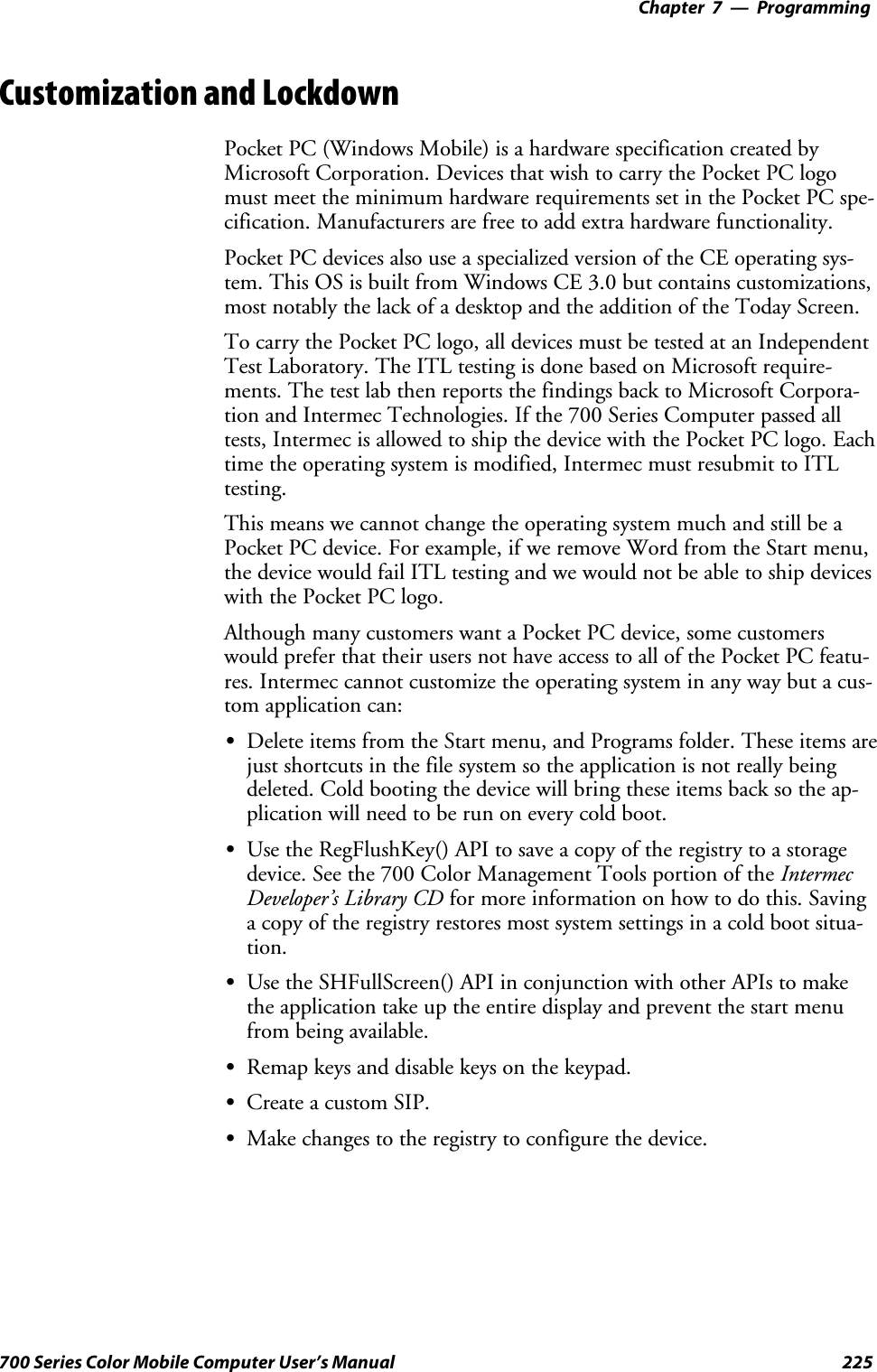
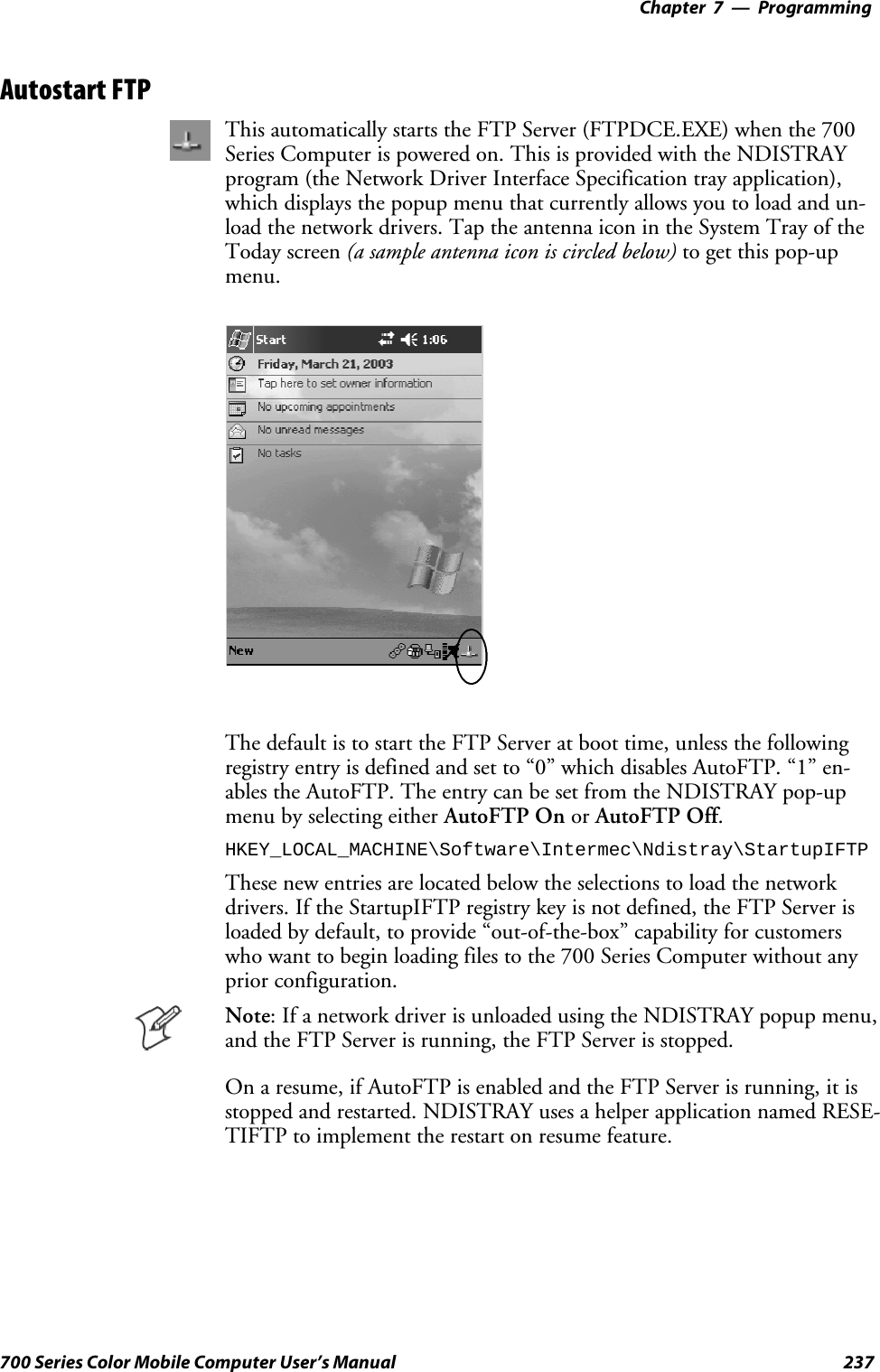
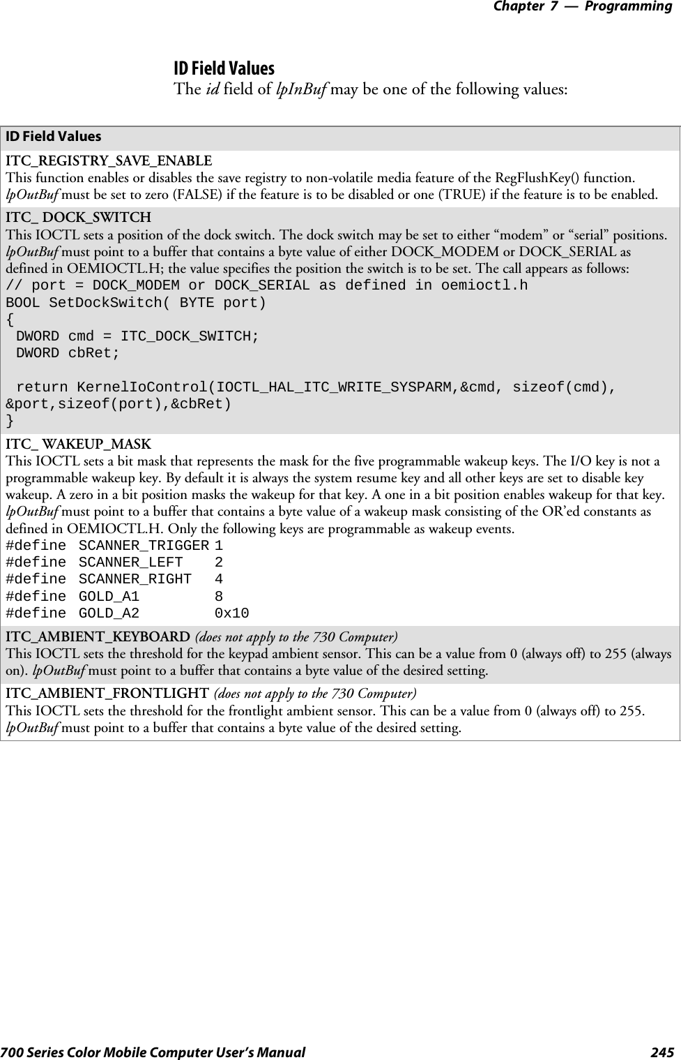
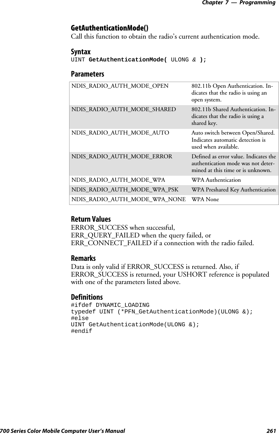
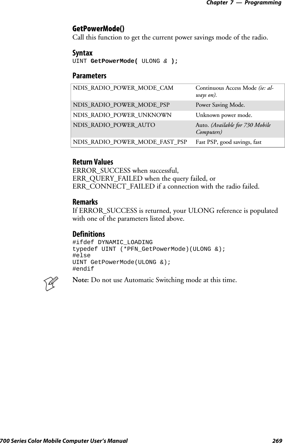
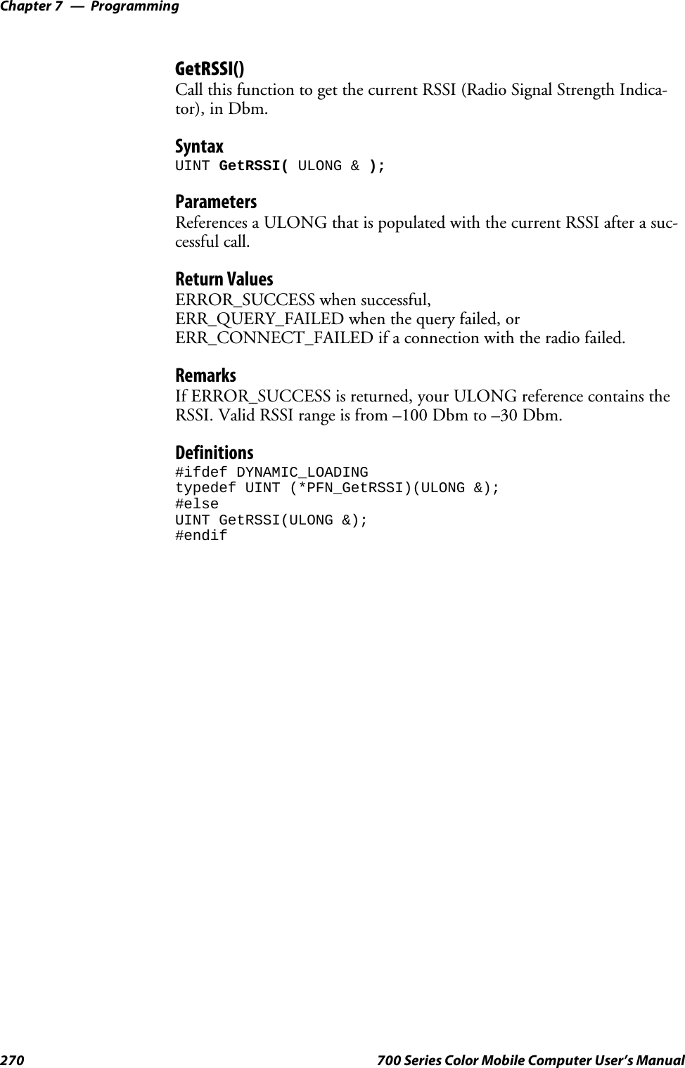
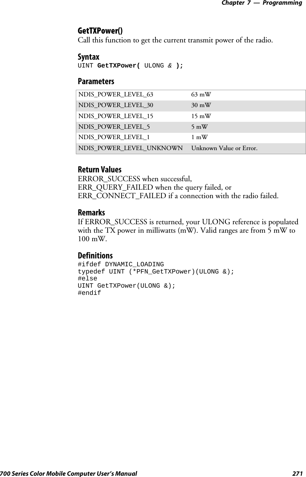
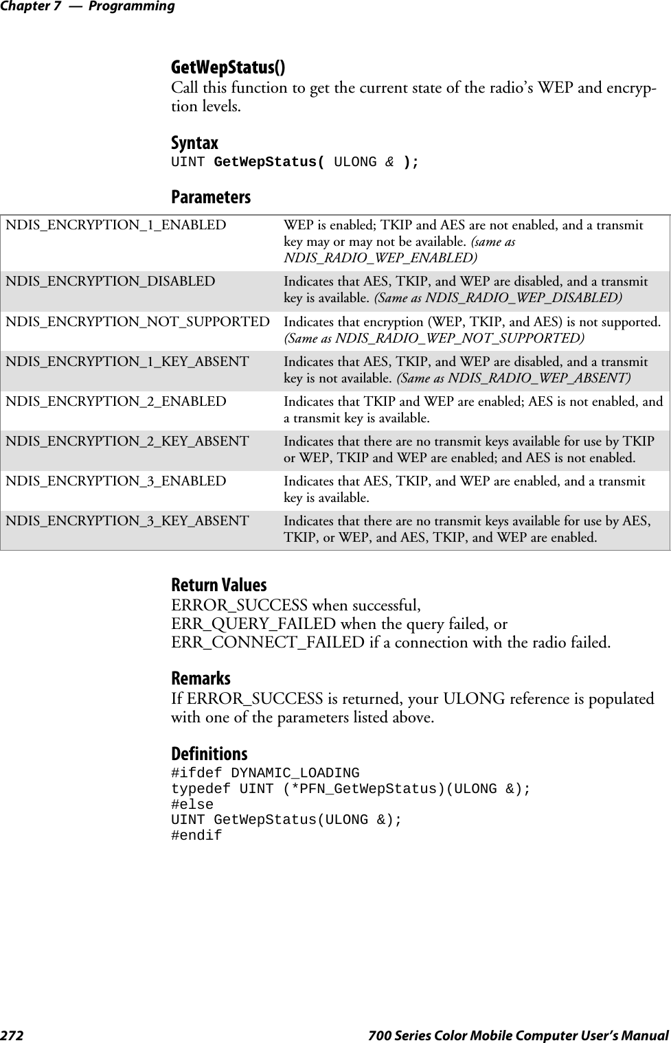
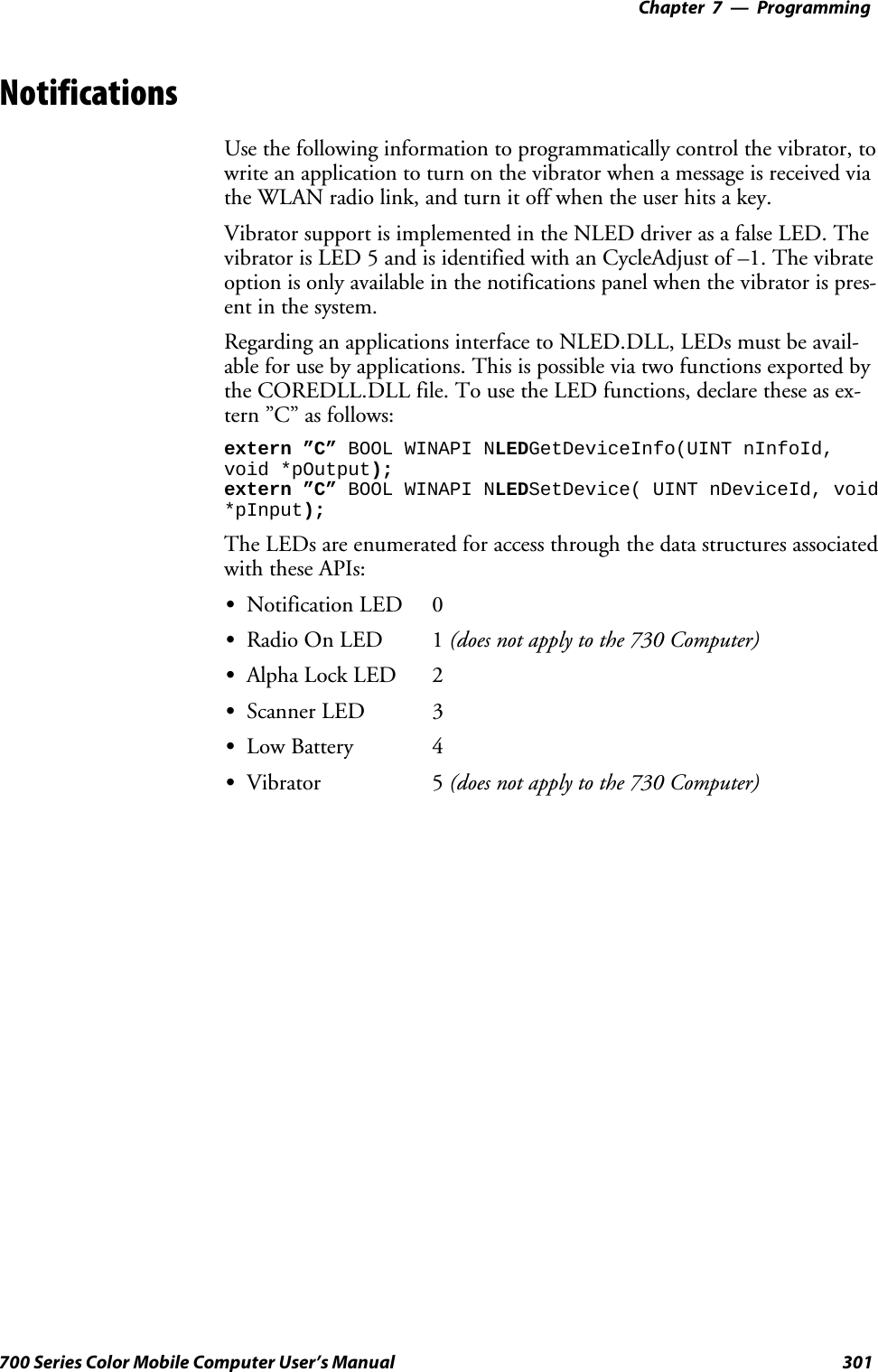
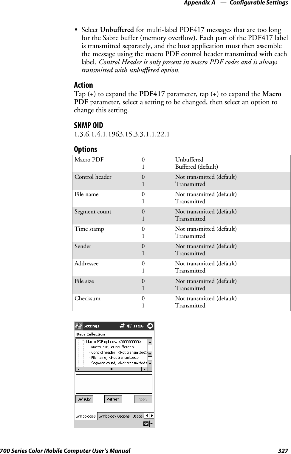
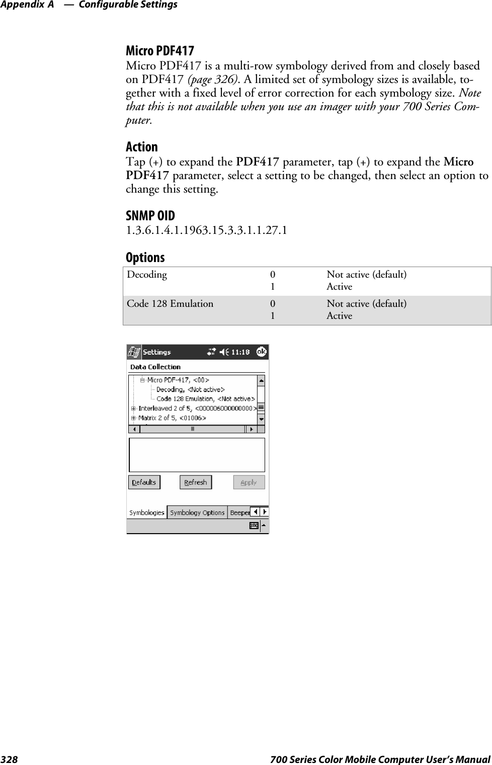
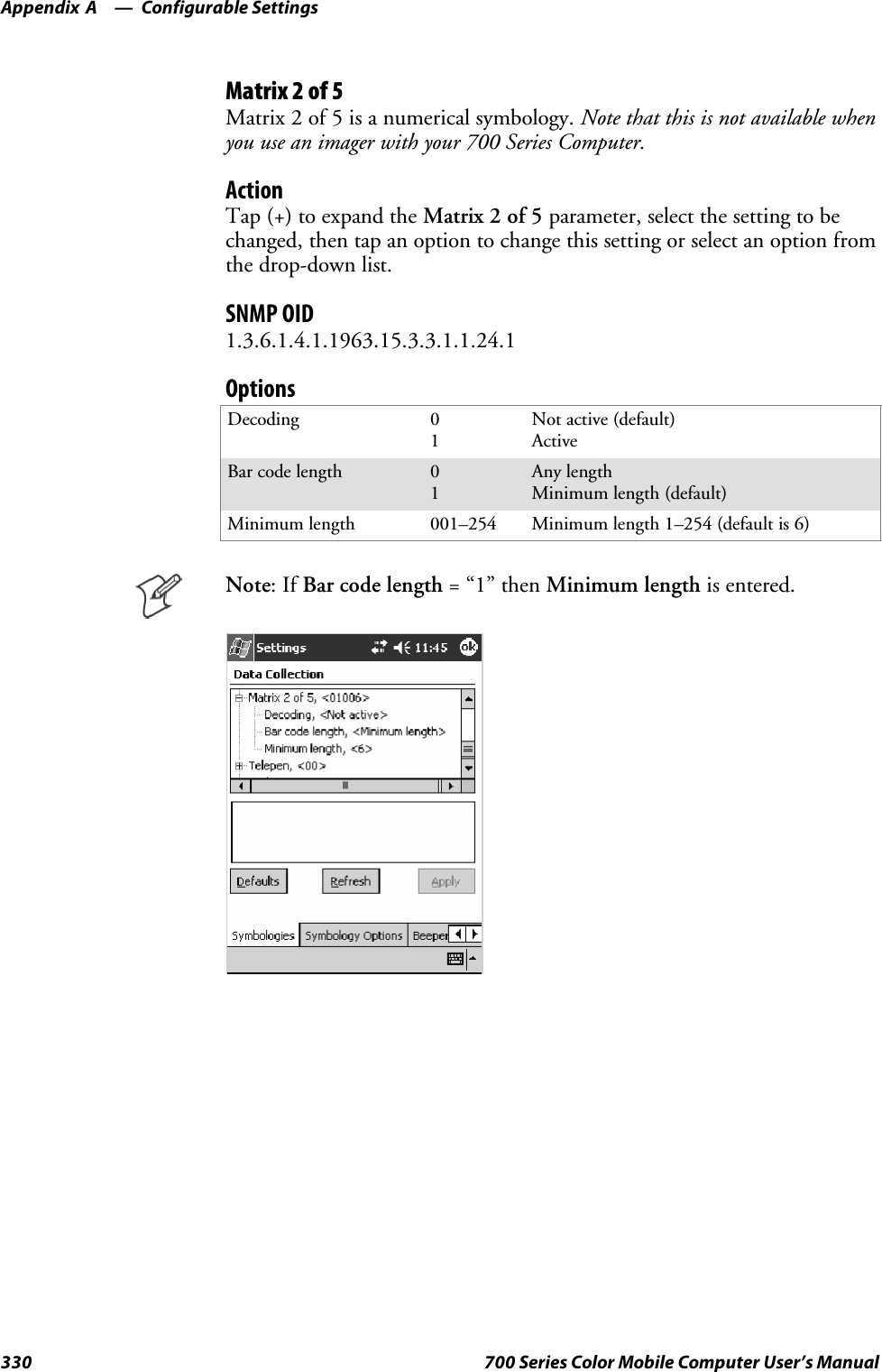
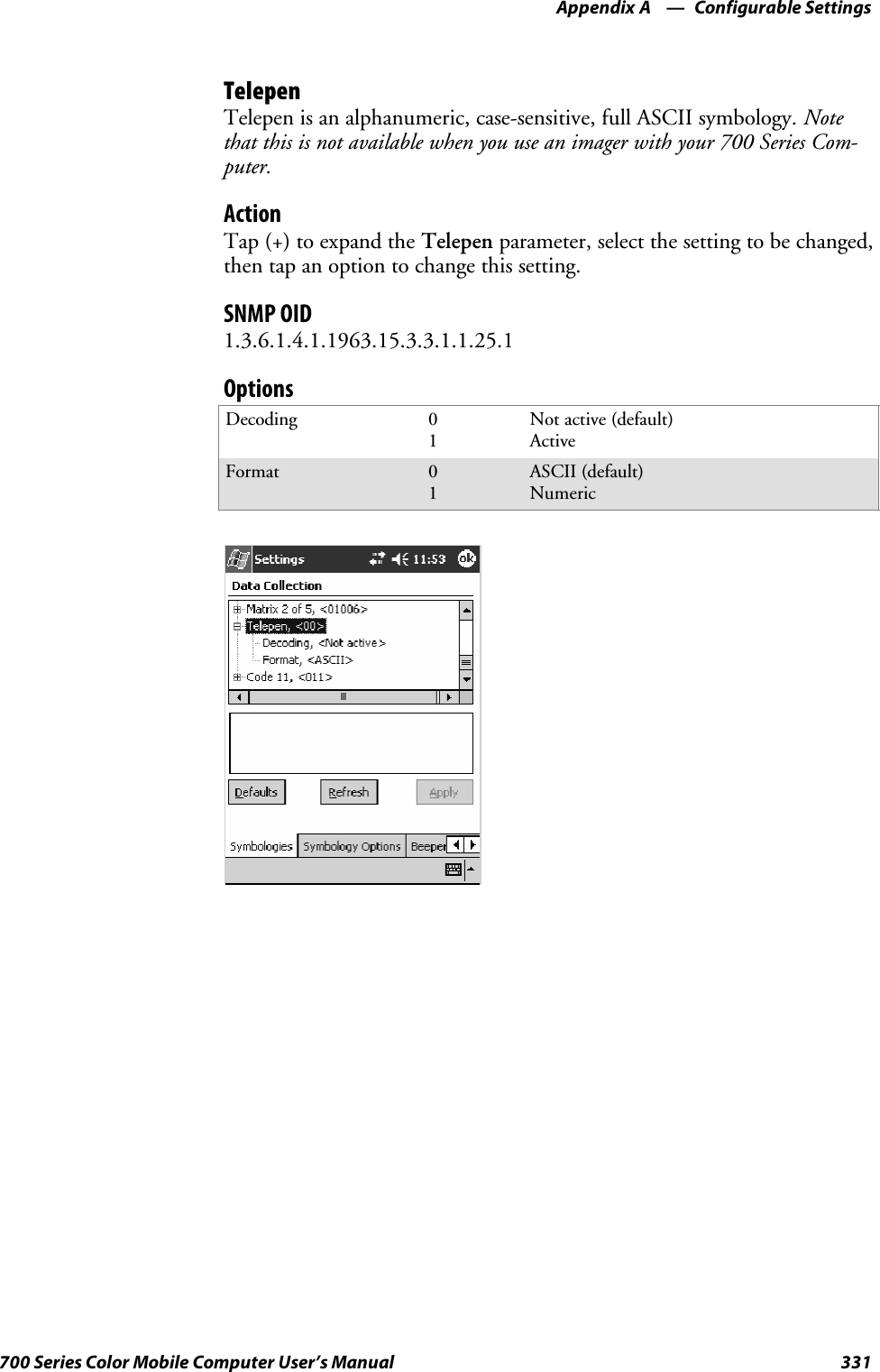
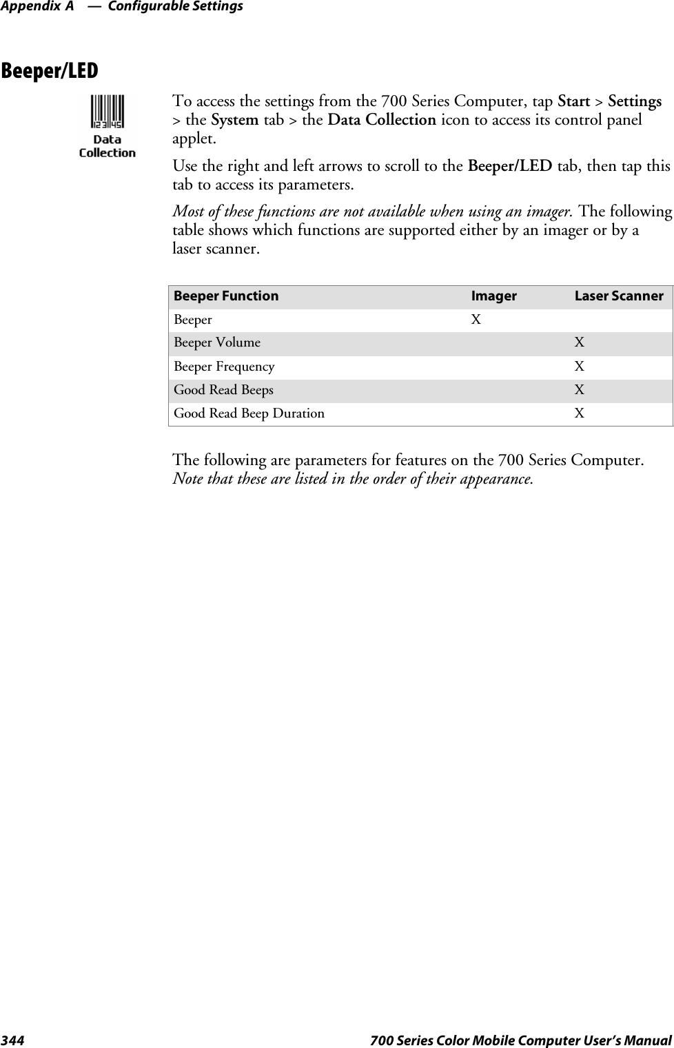
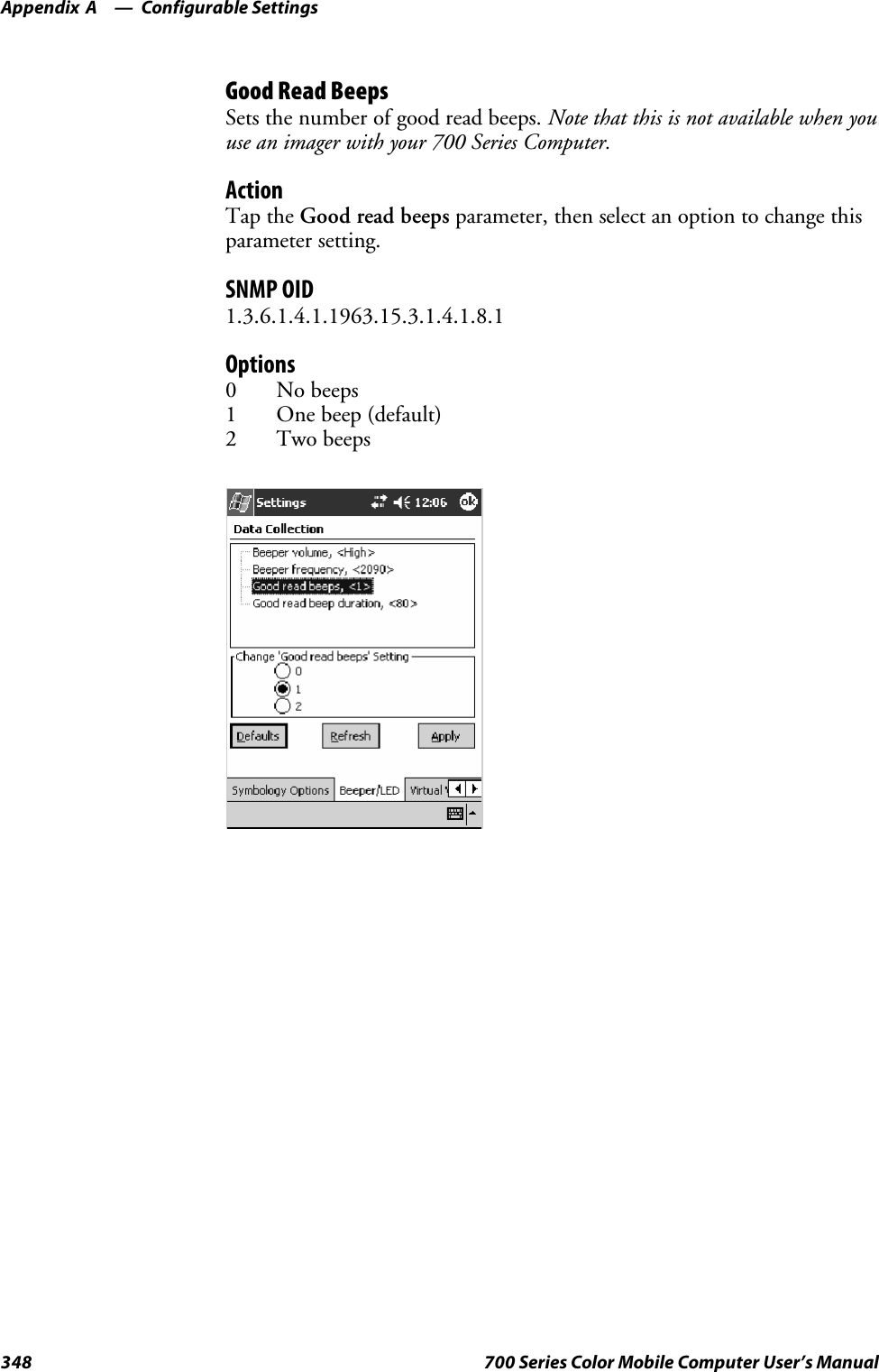
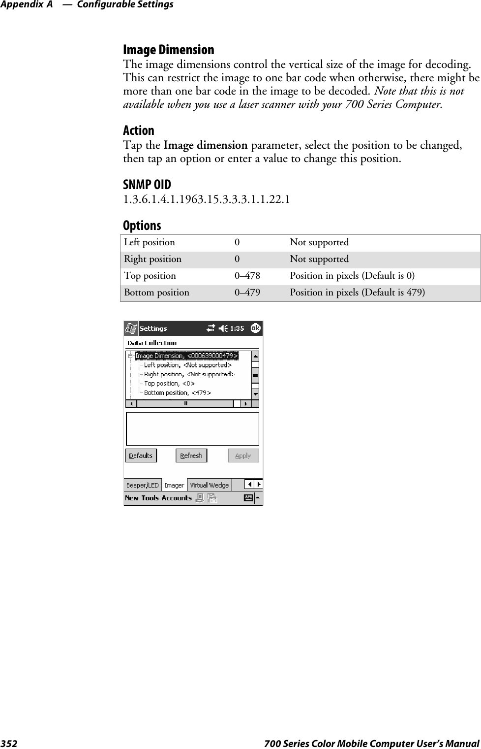
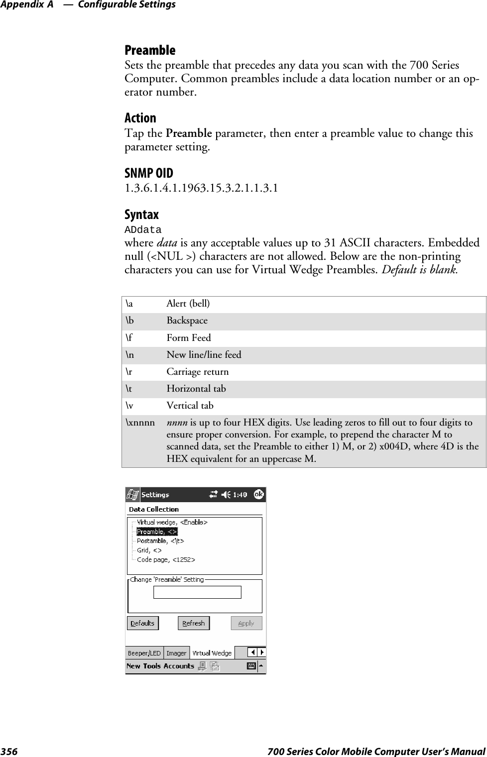
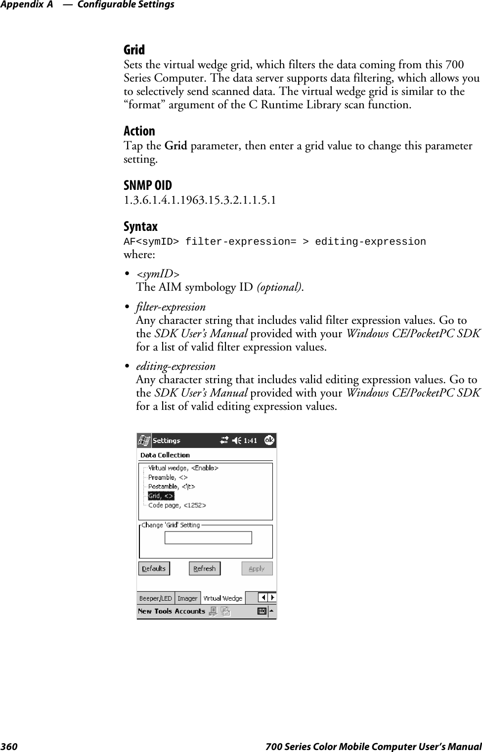
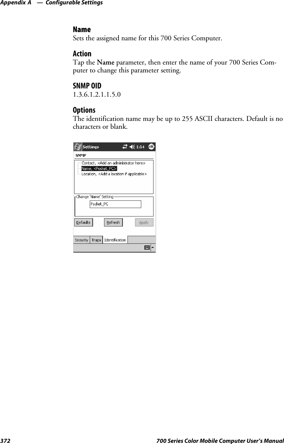
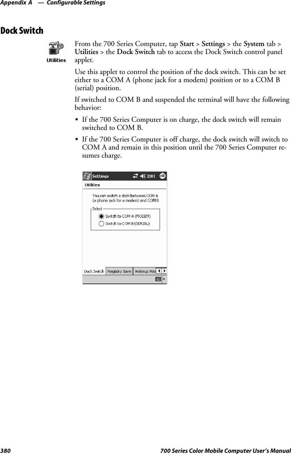
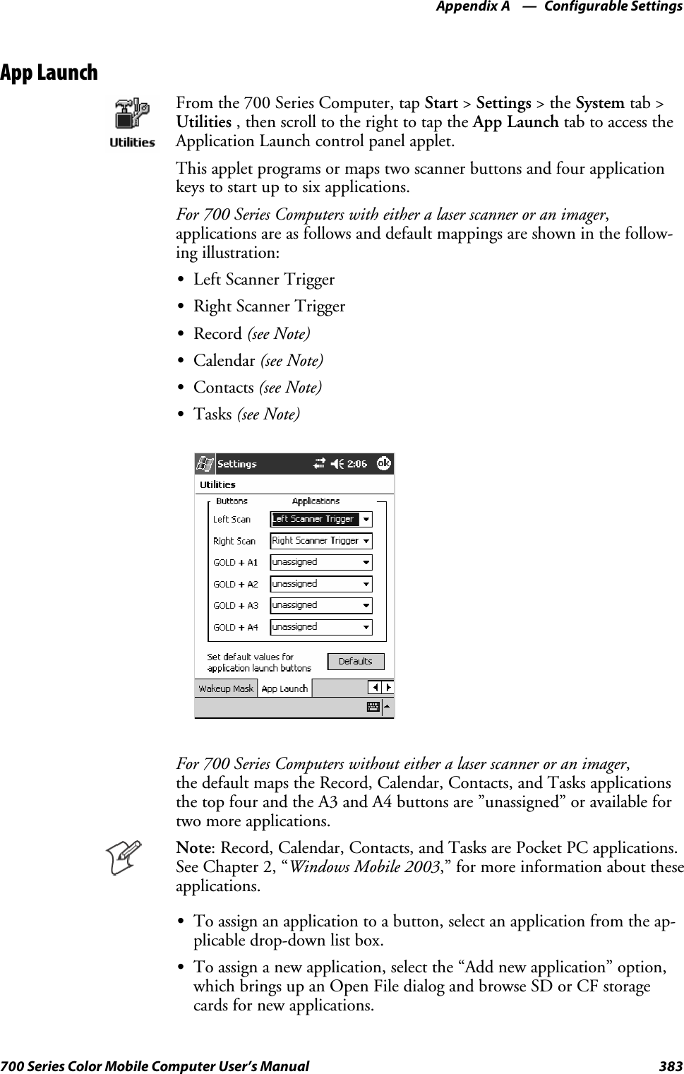
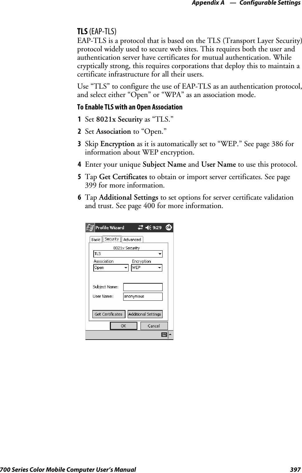
![ProgrammingChapter —7208 700 Series Color Mobile Computer User’s ManualCreating CAB FilesThe Windows CE operating system uses a .CAB file to install an applica-tion on a Windows CE-based device. A .CAB file is composed of multiplefiles that are compressed into one file. Compressing multiple files into onefile provides the following benefits:SAll application files are present.SA partial installation is prevented.SThe application can be installed from several sources, such as a desktopcomputer or a Web site.Use the CAB Wizard application (CABWIZ.EXE) to generate a .CAB filefor your application.Creating Device-Specific CAB FilesDo the following to create a device-specific .CAB file for an application, inthe order provided:1Create an .INF file with Windows CE-specific modifications (page208).2Optional Create a SETUP.DLL file to provide custom control of theinstallation process (page 220).3Use the CAB Wizard to create the .CAB file, using the .INF file, theoptional SETUP.DLL file, and the device-specific application files asparameters (page 223).Creating an .INF FileAn .INF file specifies information about an application for the CAB Wi-zard. Below are the sections of an .INF file:[Version]This specifies the creator of the file, version, and other relevant informa-tion.Required? YesSSignature:“signature_name”“$Windows NT$”SProvider:“INF_creator”The company name of the application, such as “Microsoft.”SCESignature“$Windows CE$”Example[Version]Signature = “$Windows NT$”Provider = “Intermec”CESignature = “$Windows CE$”](https://usermanual.wiki/Intermec-Technologies/SB555-2.User-Manual-2-of-2/User-Guide-491160-Page-2.png)
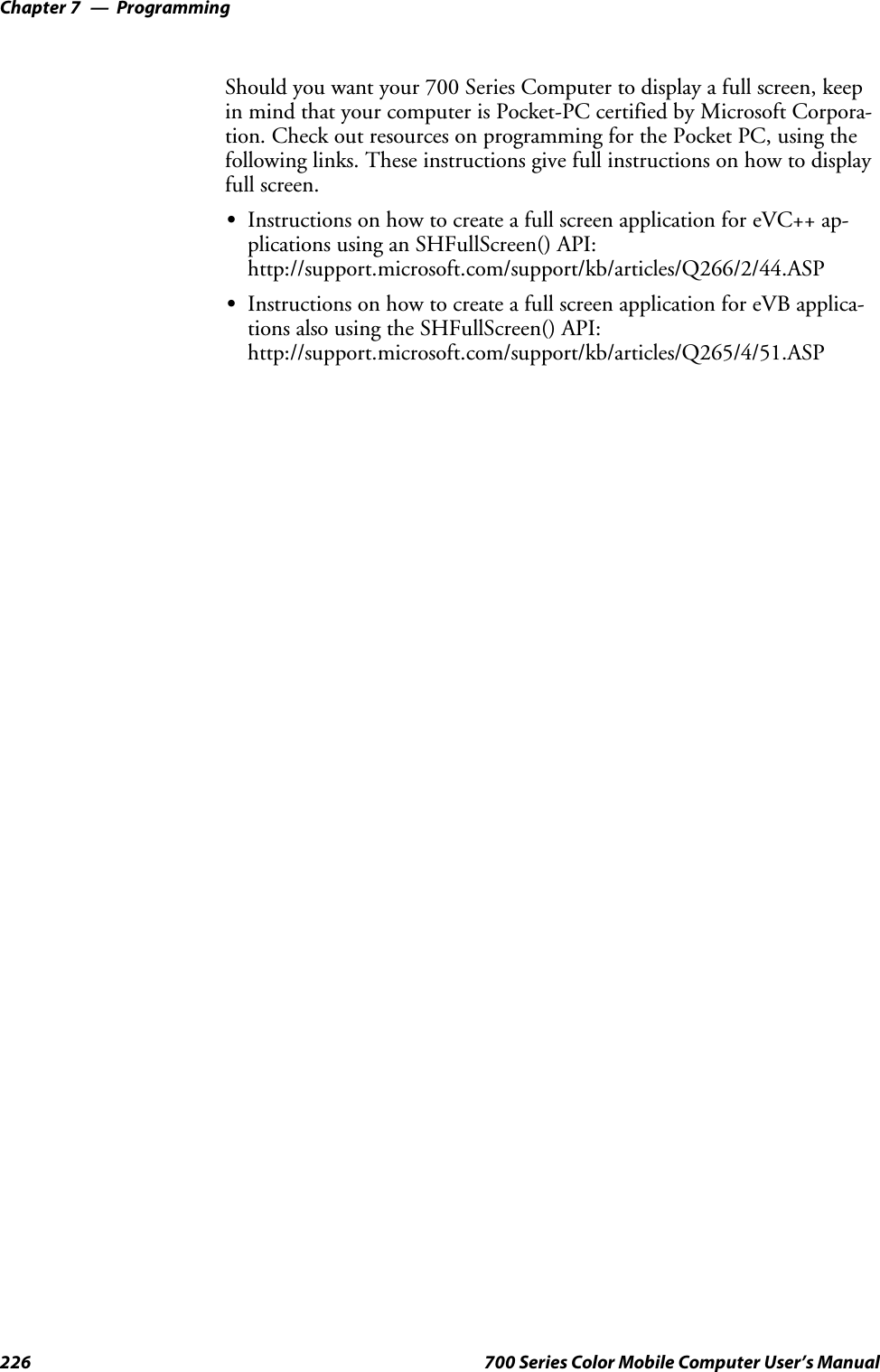
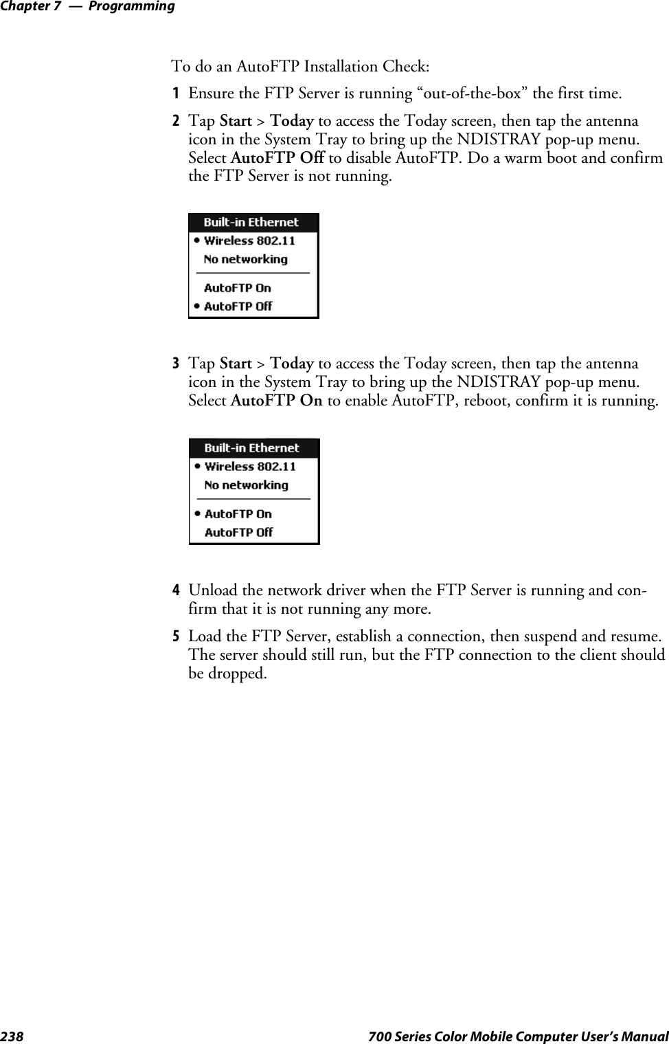
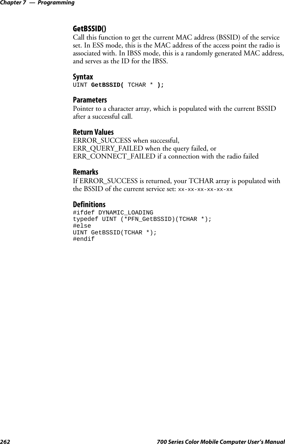
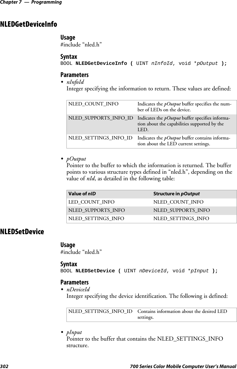
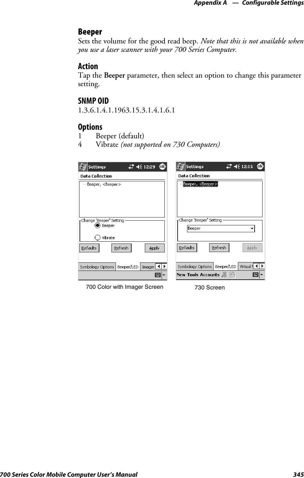
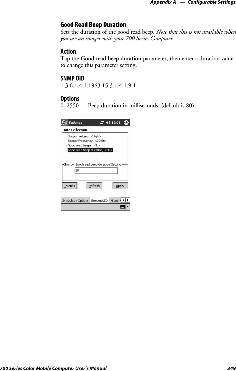
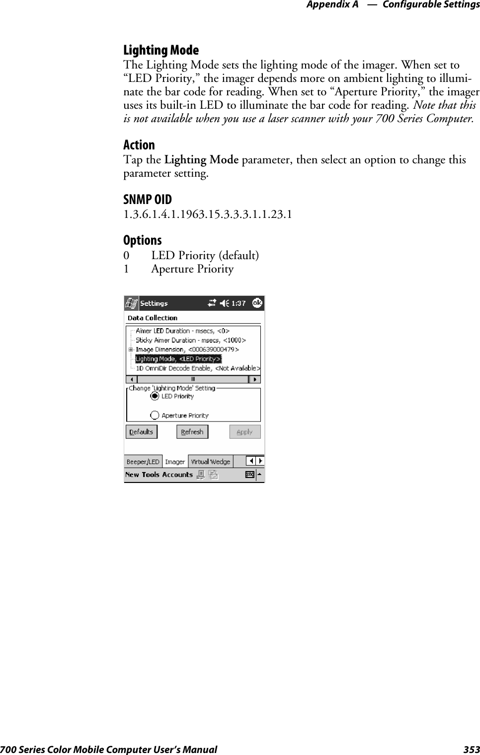
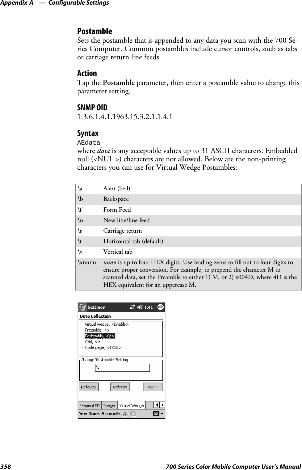
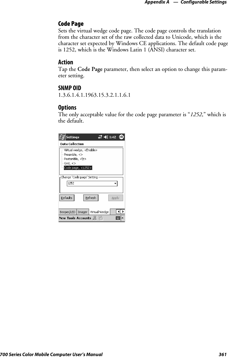
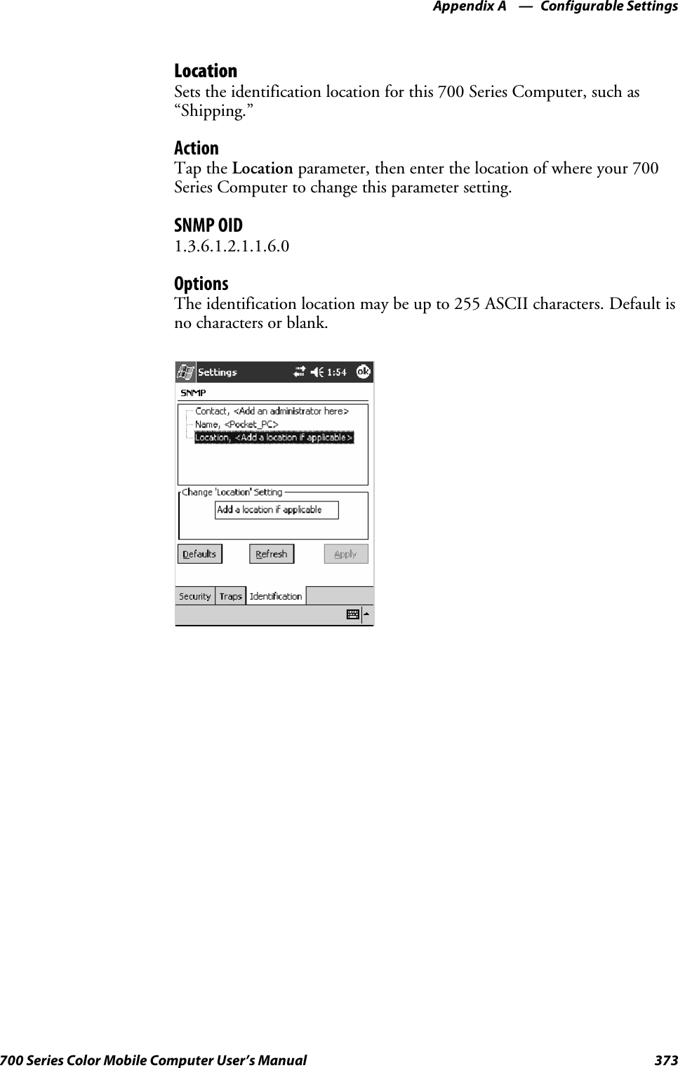
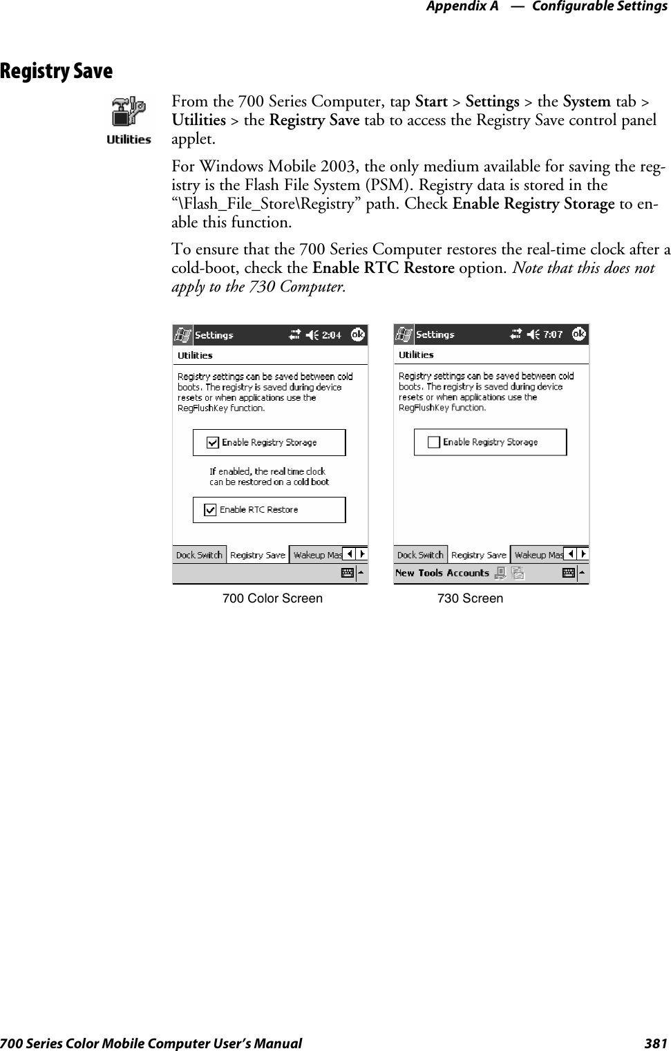
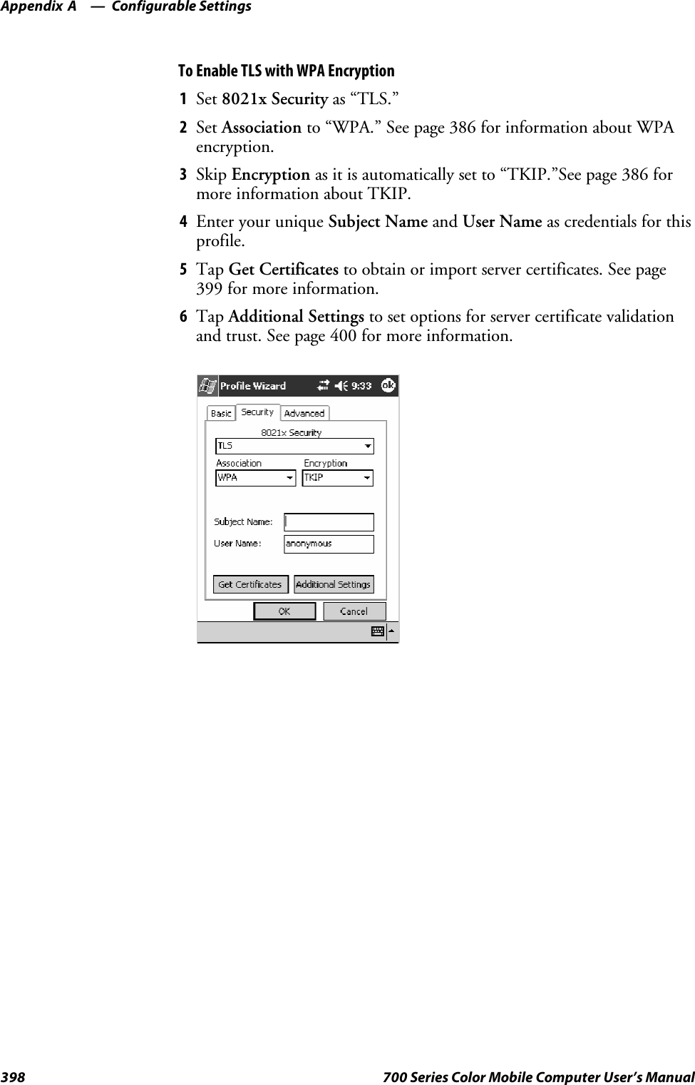
![Programming—Chapter 7209700 Series Color Mobile Computer User’s Manual[CEStrings]This specifies string substitutions for the application name and the defaultinstallation directory.Required? YesSAppName:app_nameName of the application. Other instances of %AppName% in the .INFfile are replaced with this string value, such as RP32.SInstallDir:default_install_dirDefault installation directory on the device. Other instances of %Install-Dir% in the .INF file are replaced with this string value. Example:\SDMMC_Disk\%AppName%Example[CEStrings]AppName=“Game Pack”InstallDir=%CE1%\%AppName%[Strings]This section is optional and defines one or more string keys. A string keyrepresents a string of printable characters.Required? NoSstring_key:valueString consisting of letters, digits, or other printable characters. Enclosevalue in double quotation marks ““”” if the corresponding string key isused in an item that requires double quotation marks. No string_keys isokay.Example[Strings]reg_path = Software\Intermec\My Test App](https://usermanual.wiki/Intermec-Technologies/SB555-2.User-Manual-2-of-2/User-Guide-491160-Page-3.png)
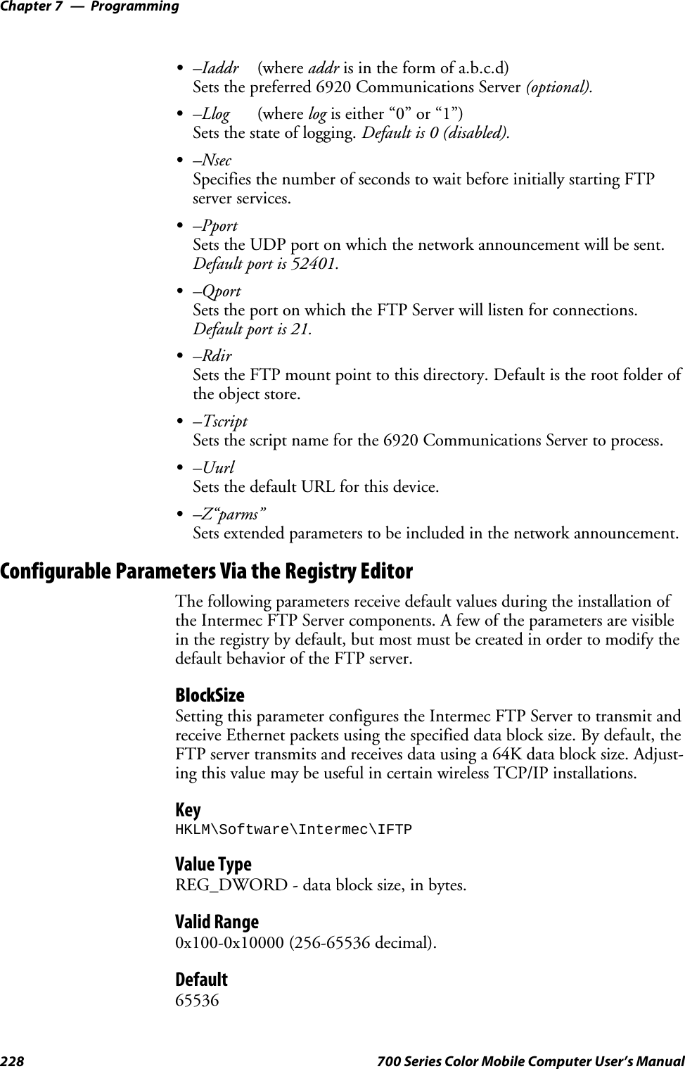
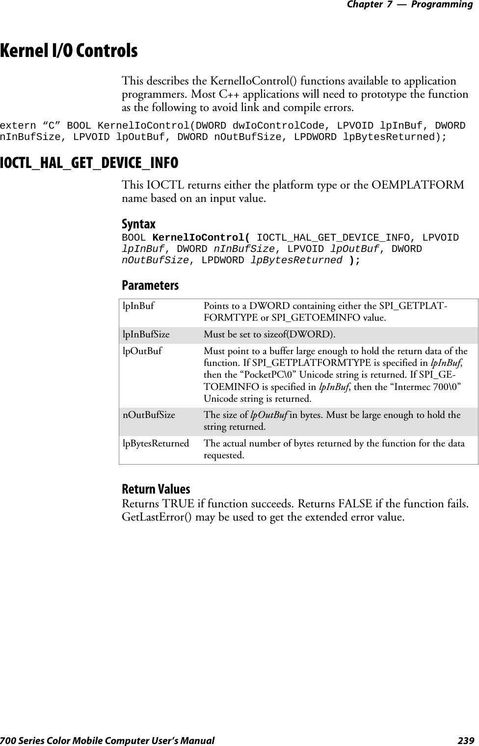
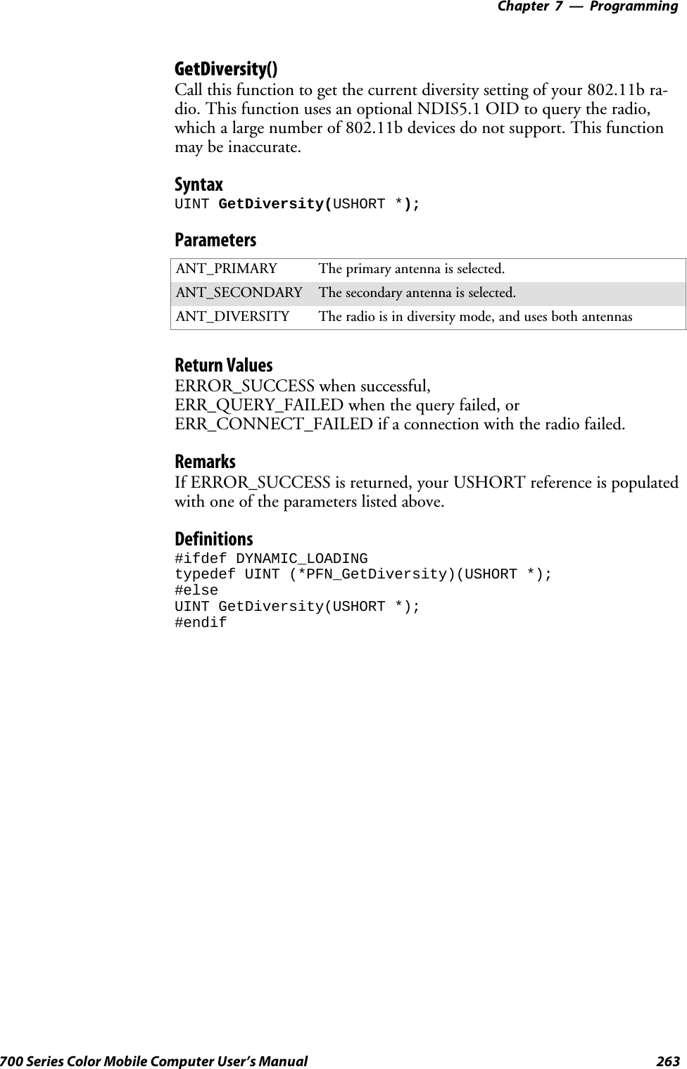
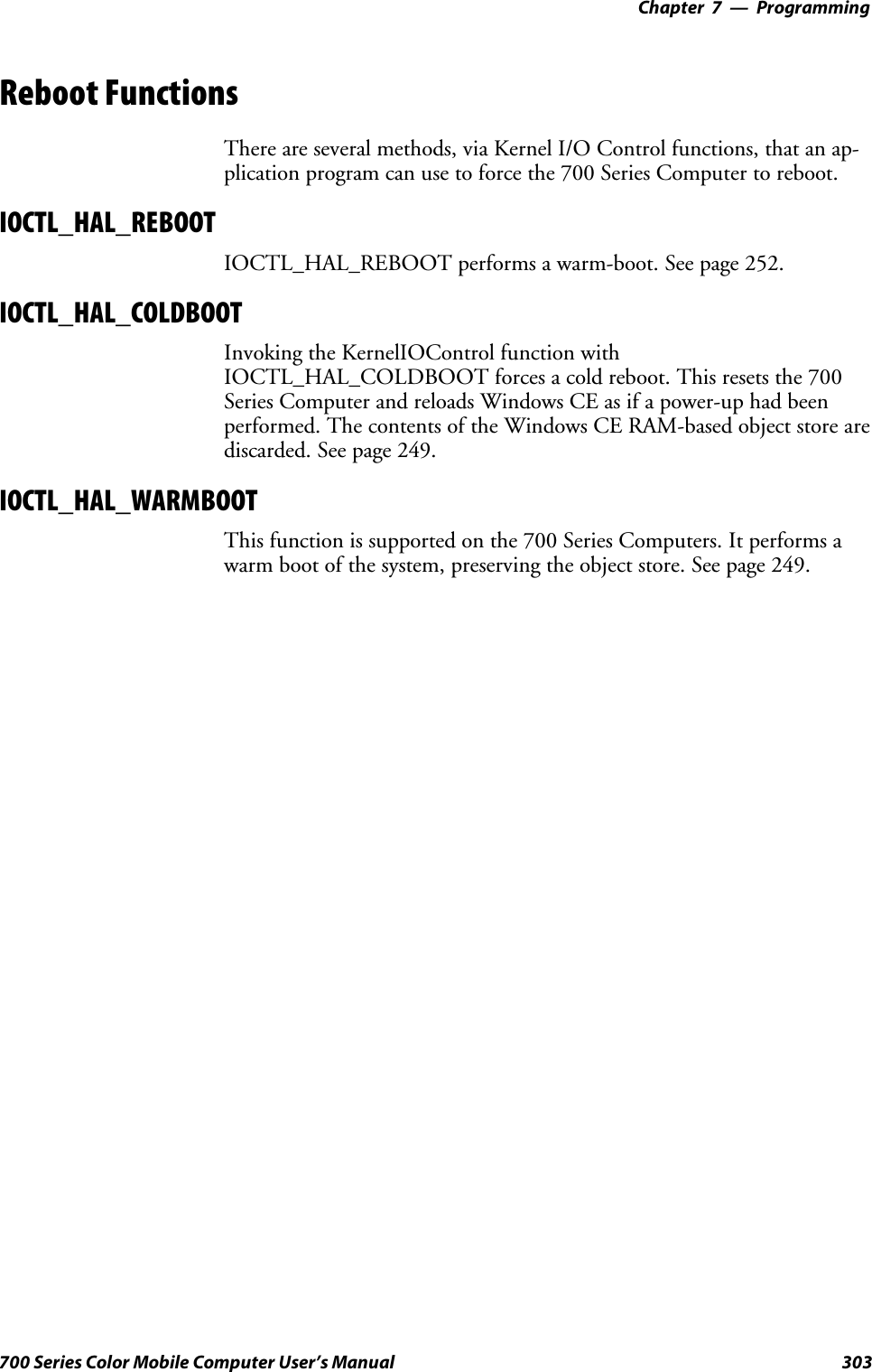
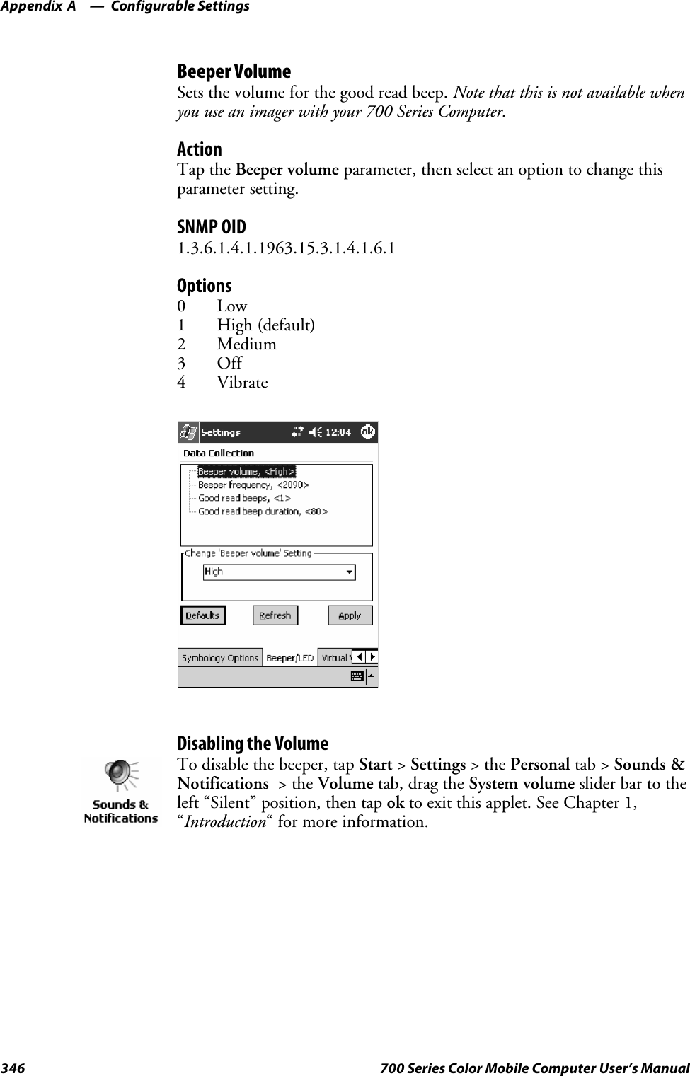
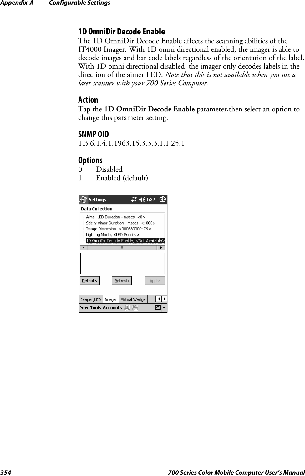
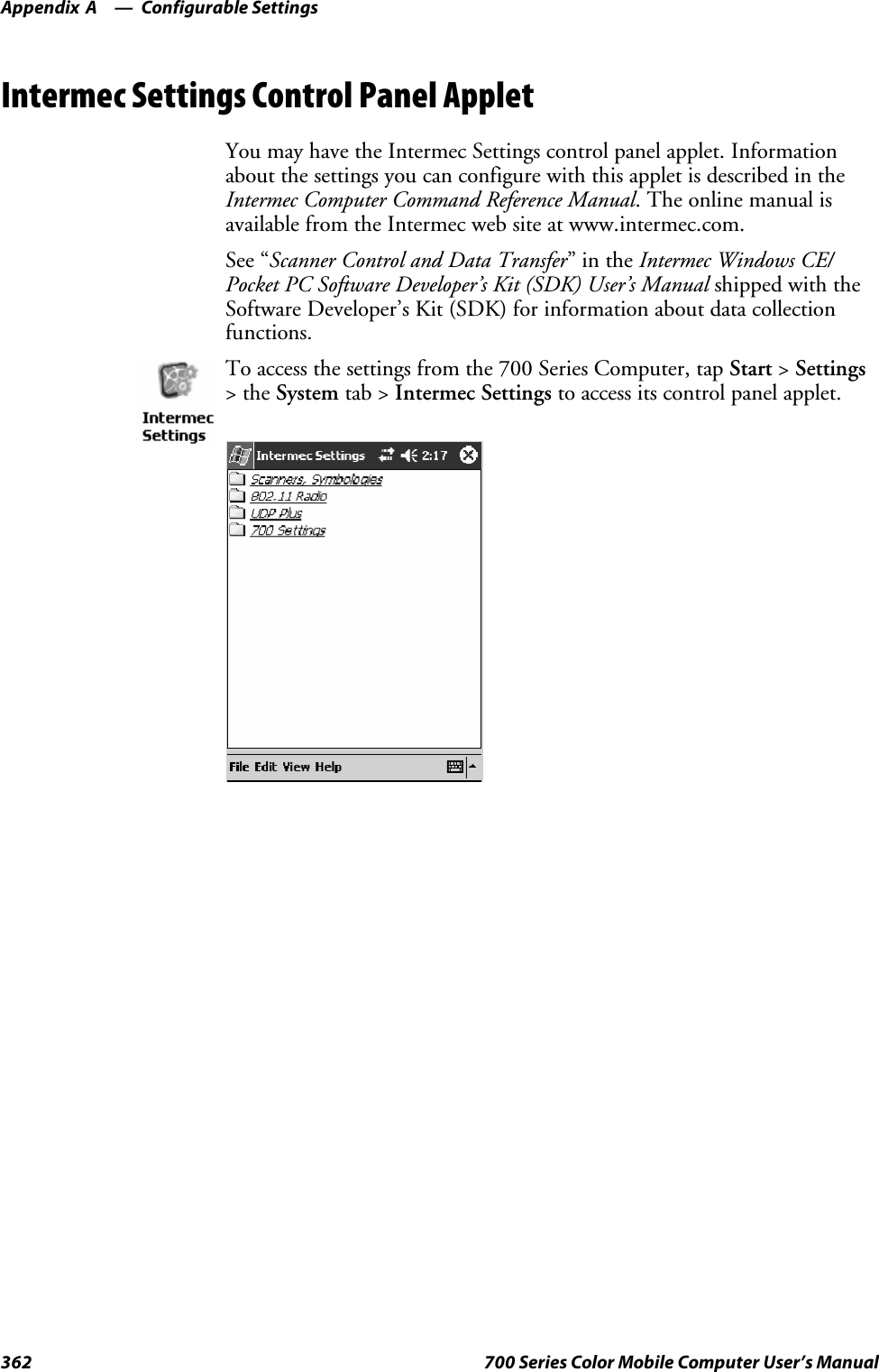
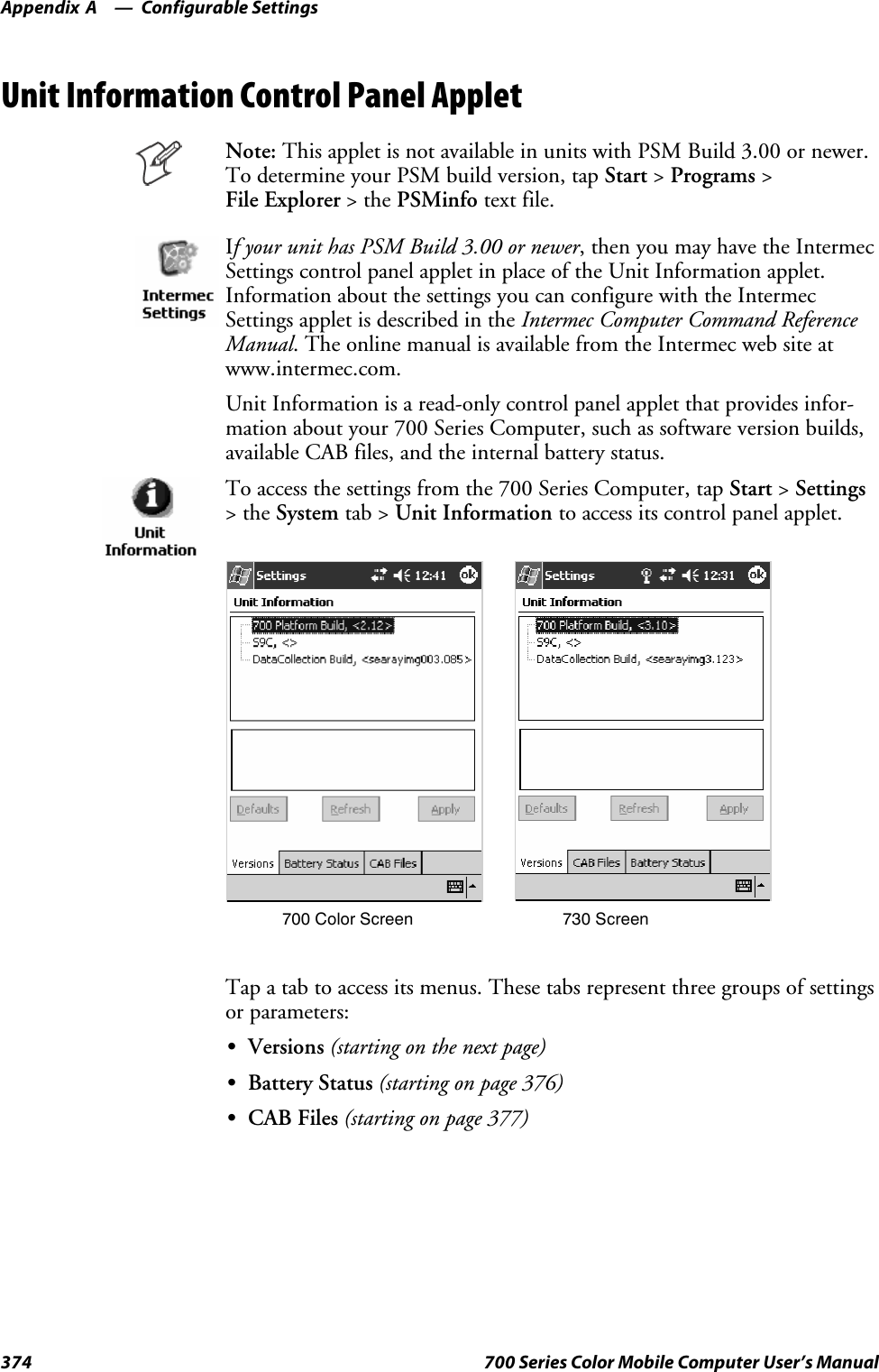
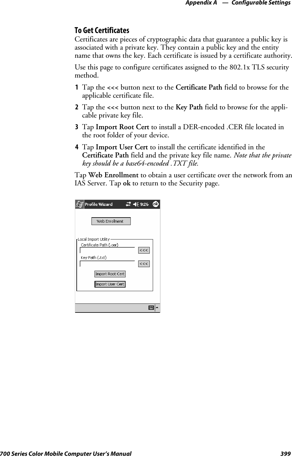
![ProgrammingChapter —7210 700 Series Color Mobile Computer User’s Manual[CEDevice]Describes the platform for the targeted application. All keys in this sectionare optional. If a key is nonexistent or has no data, Windows CE does notperform any checking with the exception being UnsupportedPlatforms.Ifthe UnsupportedPlatforms key exists but no data, the previous value is notoverridden.Required? YesSProcessorType :processor_typeThe value that is returned by SYSTEMINFO.dwProcessorType.Forexample, the value for the ARM CPU is 2577SUnsupportedPlatforms:platform_family_nameThis lists known unsupported platform family names. If the namespecified in the [CEDevice.xxx] section is different from that in the[CEDevice] section, both platform_family_name values are unsupportedfor the microprocessor specified by xxx. That is, the list of unsupportedplatform family names is appended to the previous list of unsupportednames. Application Manager will not display the application for anunsupported platform. Also, a user will be warned during the setupprocess if the .CAB file is copied to an unsupported device.Example[CEDevice]UnsupportedPlatforms = pltfrm1 ; pltfrm1 is unsupported[CEDevice.SH3]UnsupportedPlatforms = ; pltfrm1 is still unsupportedSVersionMin:minor_versionNumeric value returned by OSVERSIONINFO.dwVersionMinor. The.CAB file is valid for the currently connected device if the version ofthis device is greater than or equal to VersionMin.SVersionMax:major_versionNumeric value returned by OSVERSIONINFO.dwVersionMajor. The.CAB file is valid for the currently connected device if the version ofthis device is less than or equal to VersionMax.SBuildMin:build_numberNumeric value returned by OSVERSIONINFO.dwBuildNumber. The.CAB file is valid for the currently connected device if the version ofthis device is greater than or equal to BuildMin.SBuildMax:build_numberNumeric value returned by OSVERSIONINFO.dwBuildNumber. The.CAB file is valid for the currently connected device if the version ofthis device is less than or equal to BuildMax.](https://usermanual.wiki/Intermec-Technologies/SB555-2.User-Manual-2-of-2/User-Guide-491160-Page-4.png)
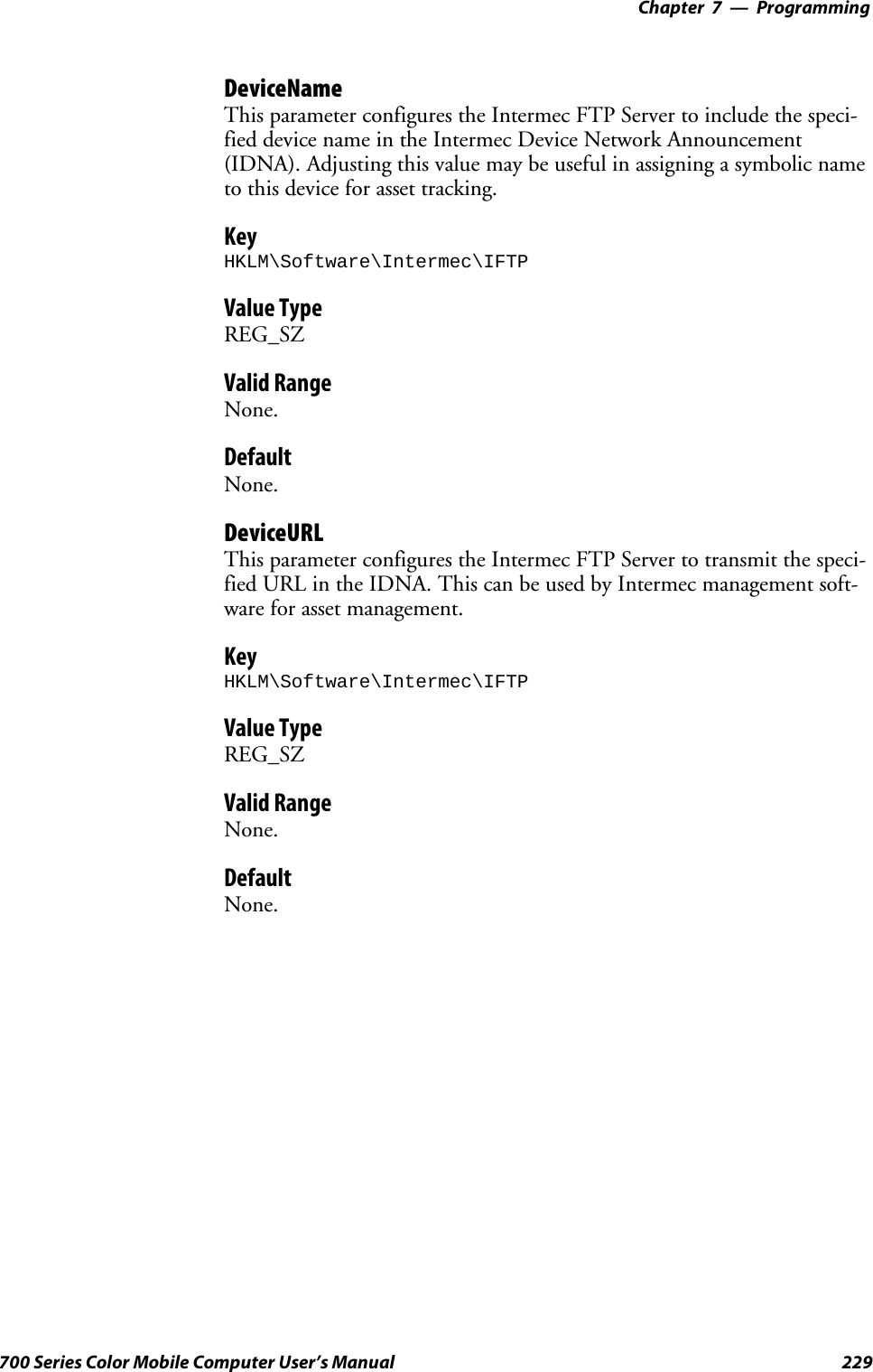
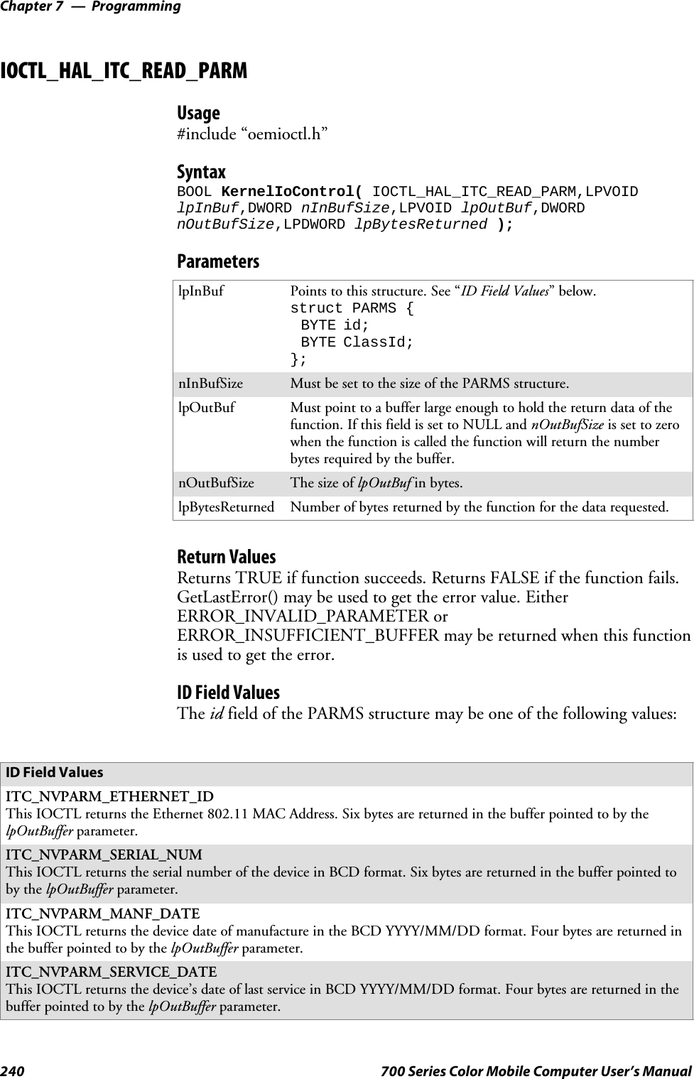
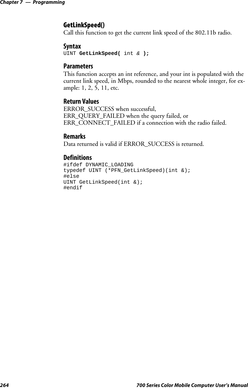
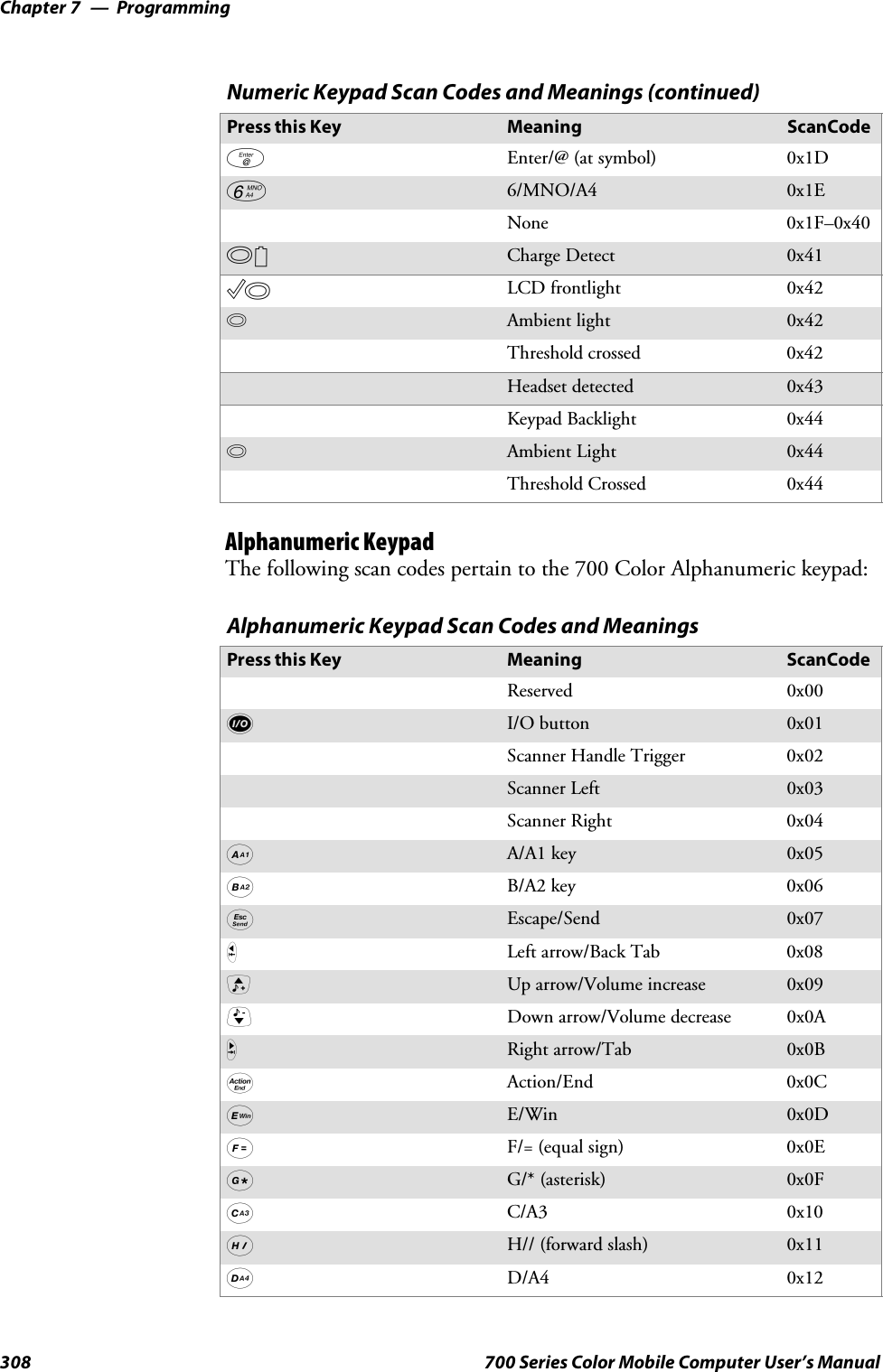
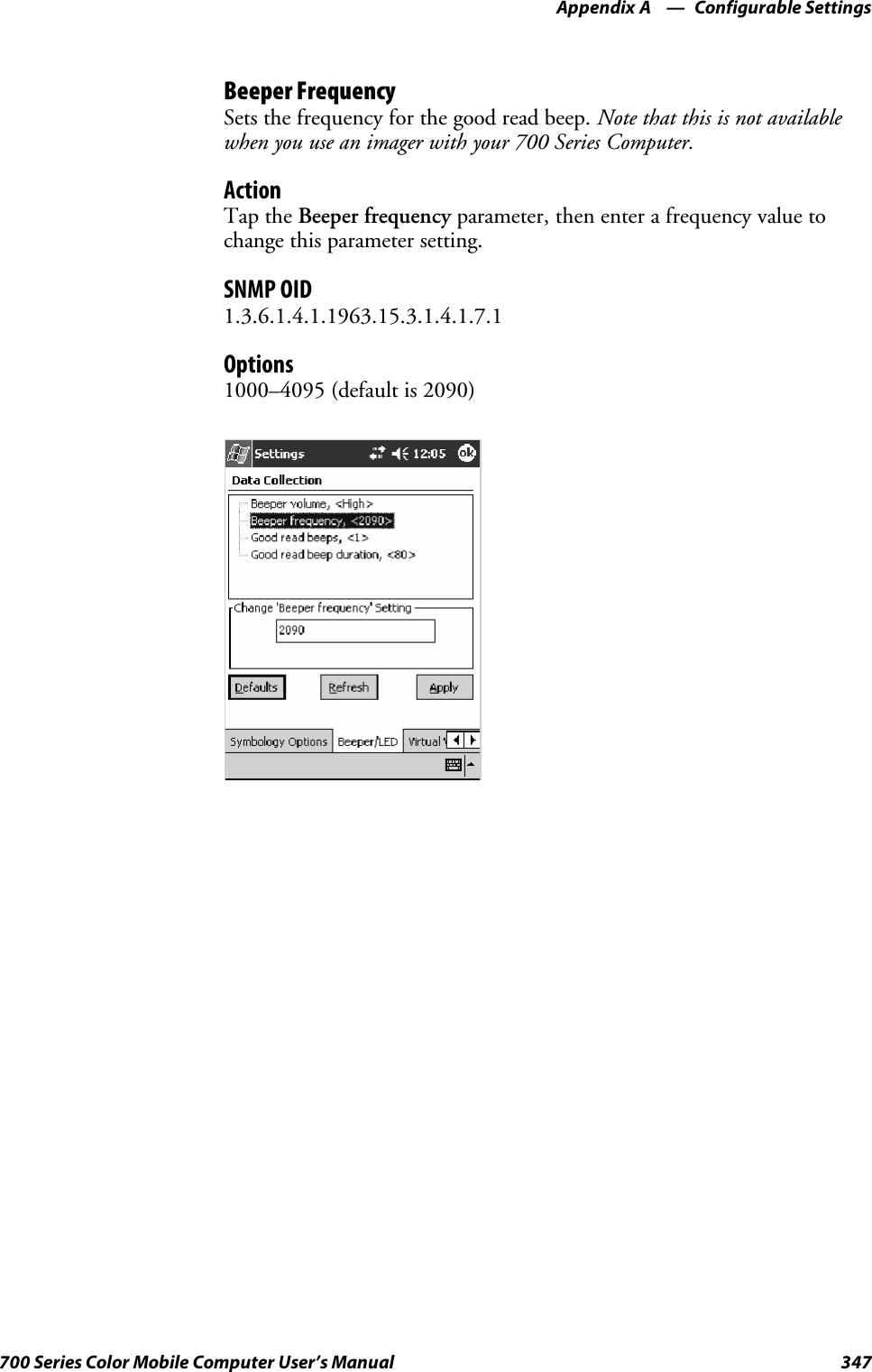
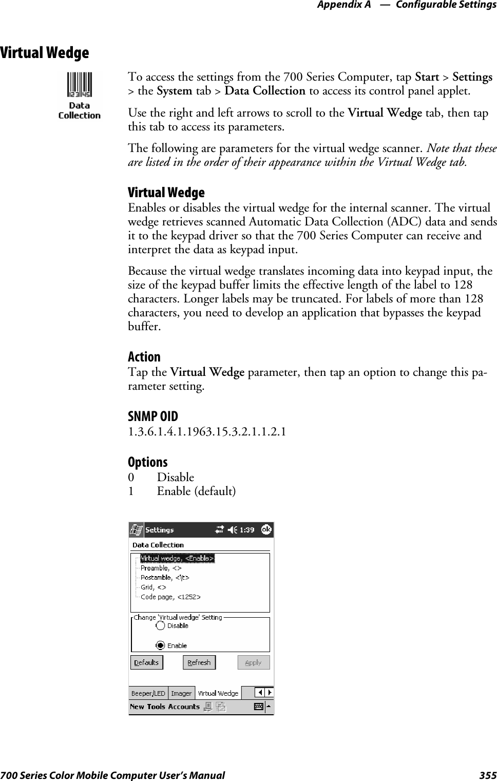
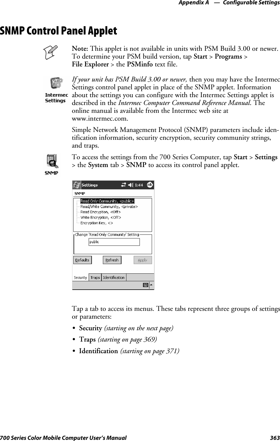
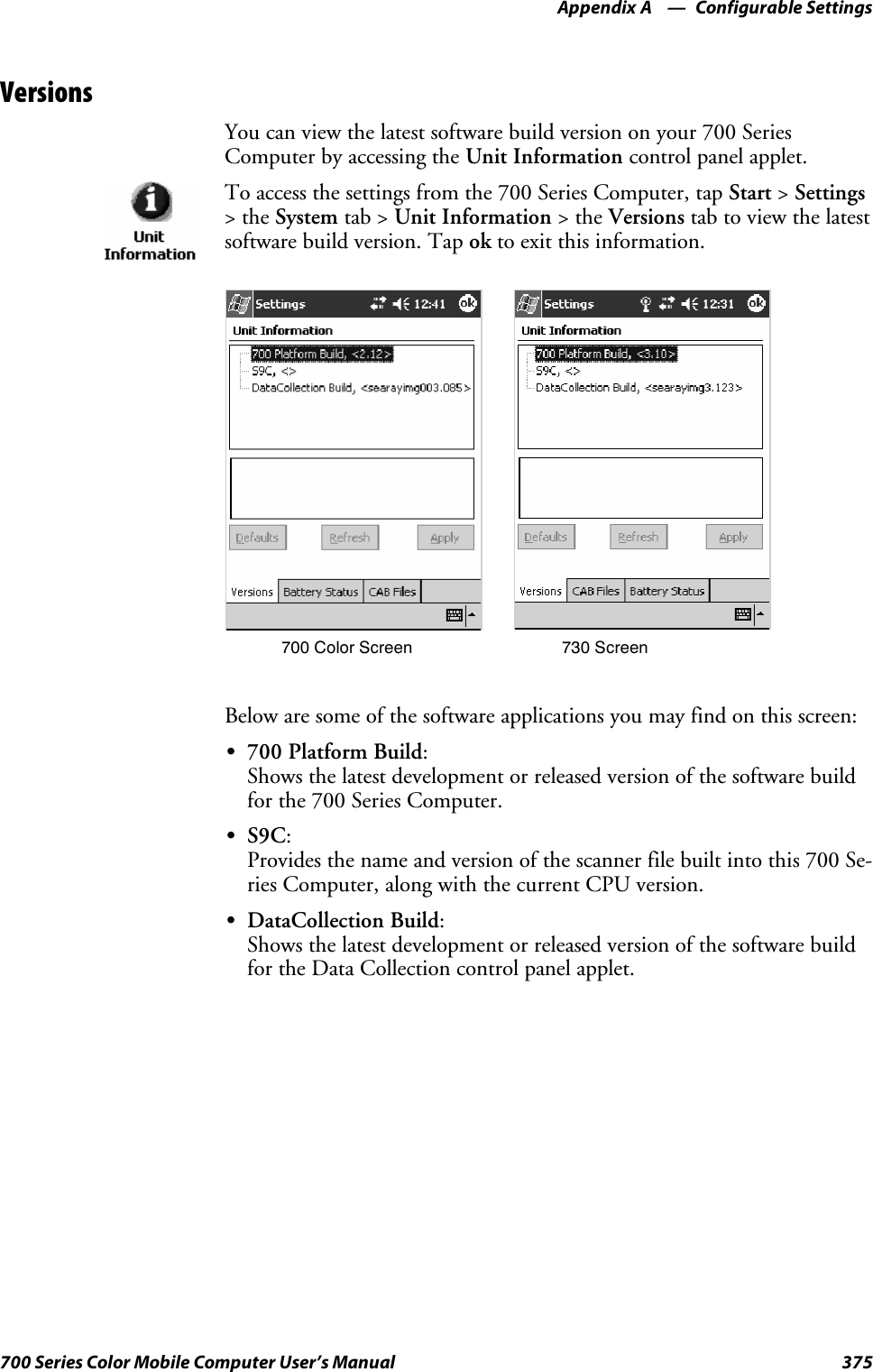
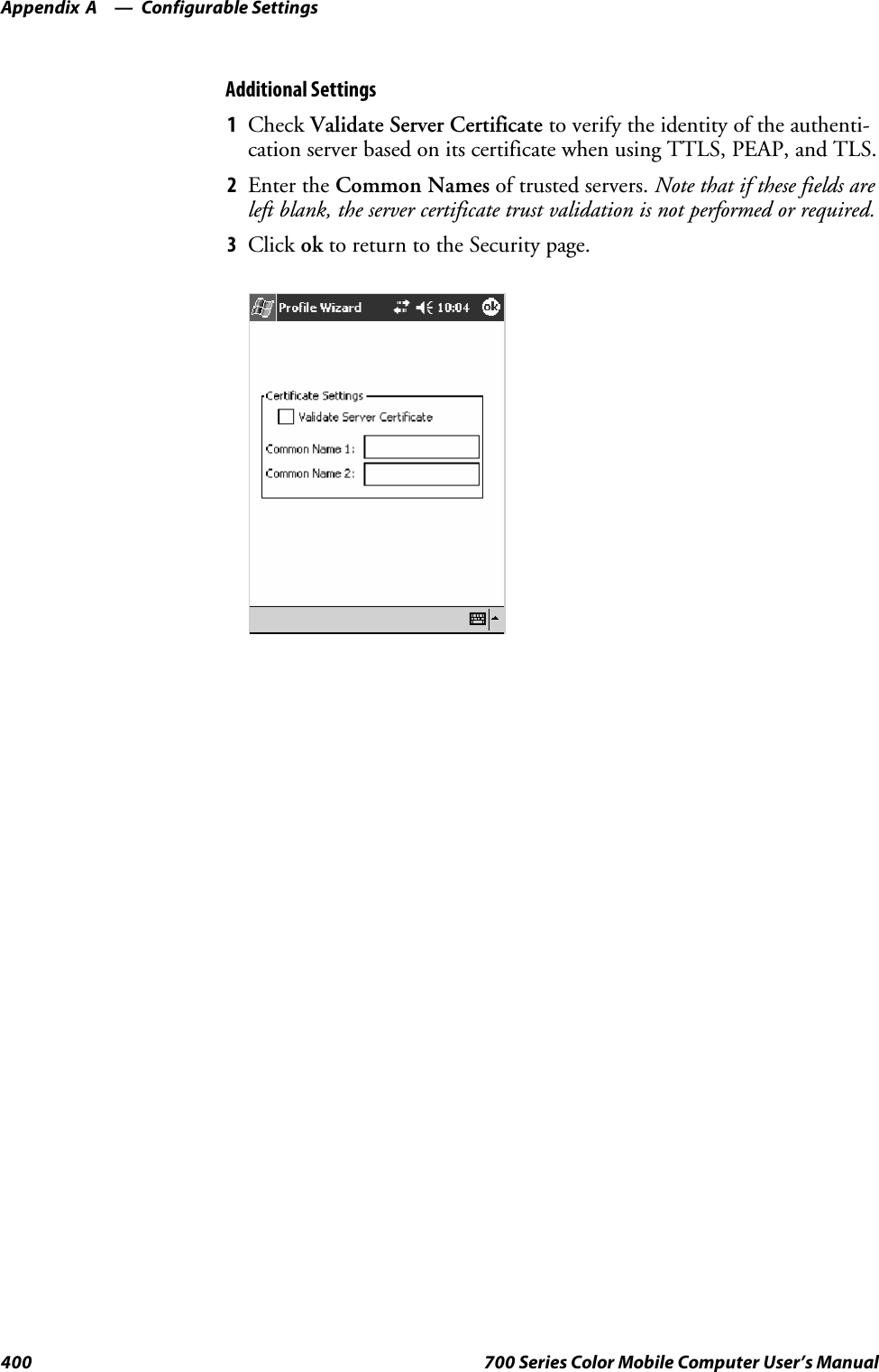
![Programming—Chapter 7211700 Series Color Mobile Computer User’s ManualExampleThe following code example shows three [CEDevice] sections: one thatgives basic information for any CPU and two that are specific to the SH3and the MIPS microprocessors.[CEDevice] ; A “template” for all platformsUnsupportedPlatforms = pltfrm1 ; Does not support pltfrm1; The following specifies version 1.0 devices only.VersionMin = 1.0VersionMax = 1.0[CEDevice.ARM] ; Inherits all [CEDevice] settings; This will create a .CAB file specific to ARM devices.ProcessorType = 2577 ; ARM .cab file is valid for ARM microprocessors.UnsupportedPlatforms = ; pltfrm1 is still unsupported; The following overrides the version settings so that no version checking isperformed.VersionMin =VersionMax =[CEDevice.MIPS] ; Inherits all [CEDevice] settings; This will create a .CAB file specific to “MIPS” devices.ProcessorType = 4000 ; MIPS .CAB file is valid for MIPSmicroprocessor.UnsupportedPlatforms =pltfrm2 ; pltfrm1,pltfrm2 unsupported for MIPs .CABfile.Note: To create the two CPU-specific .CAB files for the SETUP.INF filein the previous example, run the CAB Wizard with the “/cpu arm mips”parameter.](https://usermanual.wiki/Intermec-Technologies/SB555-2.User-Manual-2-of-2/User-Guide-491160-Page-5.png)
![ProgrammingChapter —7212 700 Series Color Mobile Computer User’s Manual[DefaultInstall]This describes the default installation of your application. Note that underthis section, you will list items expanded upon later in this description.Required? YesSCopyfiles:copyfile_list_sectionMaps to files defined later in the .INF file, such as Files.App, Files.Font,and Files.Bitmaps.SAddReg:add_registry_sectionExample: RegSettings.AllSCEShortcuts:shortcut_list_sectionString that identifies one more section that defines shortcuts to a file, asdefined in the [CEShortcuts] section.SCESetupDLL:setup_DLLOptimal string that specifies a SETUP.DLL file. It is written by the In-dependent Software Vendor (ISV) and contains customized functionsfor operations during installation and removal of the application. Thefile must be specified in the [SourceDisksFiles] section.SCESelfRegister:self_reg_DLL_filenameString that identifies files that self-register by exporting the DllRegister-Server and DllUnregisterServer Component Object Model (COM)functions. Specify these files in the [SourceDiskFiles] section. Duringinstallation, if installation on the device fails to call the file’s exportedDllRegisterServer function, the file’s exported DllUnregisterServerfunction will not be called during removal.Example[DefaultInstall]AddReg = RegSettings.AllCEShortcuts = Shortcuts.All[SourceDiskNames]This section describes the name and path of the disk on which your ap-plication resides.Required? YesSdisk_ordinal:disk_label,,path1=,“App files” , C:\Appsoft\RP32\...2=,“Font files”,,C:\RpTools\...3=,“CE Tools” ,,C:\windows ce tools...SCESignature: “$Windows CE$”Example[SourceDisksNames] ; Required section1 = ,“Common files”,,C:\app\common ; Using an absolute path[SourceDisksNames.SH3]2 = ,“SH3 files”,,sh3 ; Using a relative path[SourceDisksNames.MIPS]2 = ,“MIPS files”,,mips ; Using a relative path](https://usermanual.wiki/Intermec-Technologies/SB555-2.User-Manual-2-of-2/User-Guide-491160-Page-6.png)
![Programming—Chapter 7213700 Series Color Mobile Computer User’s Manual[SourceDiskFiles]This describes the name and path of the files in which your applicationresides.Required? YesSfilename:disk_number[,subdir]RPM.EXE = 1,c:\appsoft\...WCESTART.INI = 1RPMCE212.INI = 1TAHOMA.TTF = 2Note:[,subdir] is relative to the location of the INF file.Example[SourceDisksFiles] ; Required sectionbegin.wav = 1end.wav = 1sample.hlp = 1[SourceDisksFiles.SH3]sample.exe = 2 ; Uses the SourceDisksNames.SH3 identification of 2.[SourceDisksFiles.MIPS]sample.exe = 2 ; Uses the SourceDisksNames.MIPS identification of 2.](https://usermanual.wiki/Intermec-Technologies/SB555-2.User-Manual-2-of-2/User-Guide-491160-Page-7.png)
![ProgrammingChapter —7214 700 Series Color Mobile Computer User’s Manual[DestinationDirs]This describes the names and paths of the destination directories for theapplication on the target device. Note Windows CE does not support directo-ry identifiers.Required? YesSfile_list_section:0,subdirString that identifies the destination directory. The following list showsthe string substitutions supported by Windows CE. Use these only forthe beginning of the path. \%CE1% \Program Files%CE2% \Windows%CE3% \My Documents%CE4% \Windows\Startup%CE5% \My Documents%CE6% \Program Files\Accessories%CE7% \Program Files\Communication%CE8% \Program Files\Games%CE9% \Program Files\Pocket Outlook%CE10% \Program Files\Office%CE11% \Windows\Start Menu\Programs%CE12% \Windows\Start Menu\Programs\Accessories%CE13% \Windows\Start Menu\Programs\Communications%CE14% \Windows\Start Menu\Programs\Games%CE15% \Windows\Fonts%CE16% \Windows\Recent%CE17% \Windows\Start Menu%InstallDir%Contains the path to the target directory selected during installation. Itis declared in the [CEStrings] section%AppName%Contains the application name defined in the [CEStrings] section.Example[DestinationDirs]Files.Common = 0,%CE1%\My Subdir ; \Program Files\My SubdirFiles.Shared = 0,%CE2% ; \Windows](https://usermanual.wiki/Intermec-Technologies/SB555-2.User-Manual-2-of-2/User-Guide-491160-Page-8.png)
![Programming—Chapter 7215700 Series Color Mobile Computer User’s Manual[CopyFiles]This section, under the [DefaultInstall] section, describes the default filesto copy to the target device. Within the [DefaultInstall] section, files werelisted that must be defined elsewhere in the INF file. This section identi-fies that mapping and may contain flags.Required? YesScopyfile_list_section:destination_filename,[source_filename]The source_filename parameter is optional if it is the same as destina-tion_filename.Scopyfile_list_section:flagsThe numeric value that specifies an action to be done while copying fi-les. The following table shows values supported by Windows CE.Flag Value DescriptionCOPYFLG_WARN_IF_SKIP 0x00000001 Warn user if skipping a file is attempted after error.COPYFLG_NOSKIP 0x00000002 Do not allow a user to skip copying a file.COPYFLG_NO_OVERWRITE 0x00000010 Do not overwrite files in destination directory.COPYFLG_REPLACEONLY 0x00000400 Copy the source file to the destination directory only if thefile is already in the destination directory.CE_COPYFLG_NO_DATE_DIALOG 0x20000000 Do not copy files if the target file is newer.CE_COPYFLG_NODATECHECK 0x40000000 Ignore date while overwriting the target file.CE_COPYFLG_SHARED 0x80000000 Create a reference when a shared DLL is counted.Example[DefaultInstall.SH3]CopyFiles = Files.Common, Files.SH3[DefaultInstall.MIPS]CopyFiles = Files.Common, Files.MIPS](https://usermanual.wiki/Intermec-Technologies/SB555-2.User-Manual-2-of-2/User-Guide-491160-Page-9.png)
![ProgrammingChapter —7216 700 Series Color Mobile Computer User’s Manual[AddReg]This section, under the [DefaultInstall] section, is optional and describesthe keys and values that the .CAB file adds to the device registry. Withinthe [DefaultInstall] section, a reference may have been made to thissection, such as “AddReg=RegSettings.All”. This section defines theoptions for that setting.Required? NoSadd_registry_section:registry_root_stringString that specifies the registry root location. The following list showsthe values supported by Windows CE.SHKCR Same as HKEY_CLASSES_ROOTSHKCU Same as HKEY_CURRENT_USERSHKLM Same as HKEY_LOCAL_MACHINESadd_registry_section:value_nameRegistry value name. If empty, the “default” registry value name is used.Sadd_registry_section:flagsNumeric value that specifies information about the registry key. Thefollowing table shows the values that are supported by Window CE.Flag Value DescriptionFLG_ADDREG_NOCLOBBER 0x00000002 If the registry key exists, do not overwrite it. Can be usedwith any of the other flags in this table.FLG_ADDREG_TYPE_SZ 0x00000000 REG_SZ registry data type.FLG_ADDREG_TYPE_MULTI_SZ 0x00010000 REG_MULTI_SZ registry data type. Value field that followscan be a list of strings separated by commas.FLG_ADDREG_TYPE_BINARY 0x00000001 REG_BINARY registry data type. Value field that followsmust be a list of numeric values separated by commas, onebyte per field, and must not use the 0x hexadecimal prefix.FLG_ADDREG_TYPE_DWORD 0x00010001 REG_DWORD data type. The noncompatible format in theWin32 Setup .INF documentation is supported.ExampleAddReg = RegSettings.All[RegSettings.All]HKLM,%reg_path%,,0x00000000,alpha ; <default> = “alpha”HKLM,%reg_path%,test,0x00010001,3 ; Test = 3HKLM,%reg_path%\new,another,0x00010001,6 ; New\another = 6](https://usermanual.wiki/Intermec-Technologies/SB555-2.User-Manual-2-of-2/User-Guide-491160-Page-10.png)
![Programming—Chapter 7217700 Series Color Mobile Computer User’s Manual[CEShortCuts]This section, a Windows CE-specific section under the [DefaultInstall]section, is optional and describes the shortcuts that the installation applica-tion creates on the device. Within the [DefaultInstall] section, a referencemay have been made to this section, such as “ShortCuts.All”. This sectiondefines the options for that setting.Required? NoSshortcut_list_section:shortcut_filenameString that identifies the shortcut name. It does not require the .LNKextension.Sshortcut_list_section:shortcut_type_flagNumeric value. Zero or empty represents a shortcut to a file; any non-zero numeric value represents a shortcut to a folder.Sshortcut_list_section:target_file_pathString value that specifies the destination location. Use the target filename for a file, such as MyApp.exe, that must be defined in a file copylist. For a path, use a file_list_section name defined in the [Destination-Dirs] section, such as DefaultDestDir,orthe%InstallDir% string.Sshortcut_list_section:standard_destination_pathOptional string value. A standard %CEx% path or %InstallDir%.Ifnovalue is specified, the shortcut_list_section name of the current section orthe DefaultDestDir value from the [DestinationDirs] section is used.ExampleCEShortcuts = Shortcuts.All[Shortcuts.All]Sample App,0,sample.exe ; Uses the path in DestinationDirs. SampleApp,0,sample.exe,%InstallDir% ; The path is explicitly specified.Sample .INF File[Version] ; Required sectionSignature = “$Windows NT$”Provider = “Intermec Technologies Corporation”CESignature = “$Windows CE$”;[CEDevice];ProcessorType =[DefaultInstall] ; Required sectionCopyFiles = Files.App, Files.Fonts, Files.BitMaps, Files.Intl,Files.TelecomNcsCE, Files.Windows, Files.Import, Files.Export, Files.Work,Files.Database, Files.WinCE AddReg = RegSettings.All ;CEShortcuts =Shortcuts.All[SourceDisksNames] ; Required section1 = ,“App files” ,,c:\appsoft\...2 = ,”Font files” ,,c:\WinNT\Fonts3 = ,”CE Tools” ,,c:\windows ce tools\wce400\700ie\mfc\lib\x86[SourceDisksFiles] ; Required sectionrpm.exe = 1,C:\Appsoft\program\wce400\WCEX86Rel700wcestart.ini = 1](https://usermanual.wiki/Intermec-Technologies/SB555-2.User-Manual-2-of-2/User-Guide-491160-Page-11.png)
![ProgrammingChapter —7218 700 Series Color Mobile Computer User’s Manualrpmce212.ini = 1intermec.bmp = 1rpmlogo.bmp = 1rpmname.bmp = 1import.bmp = 1export.bmp = 1clock.bmp = 1printer.bmp = 1filecopy.bmp = 1readme.txt = 1lang_eng.bin = 1rpmdata.dbd = 1,database\wce1tahoma.ttf = 2mfcce212.dll = 3olece212.dll = 3olece211.dll = 1,c:\windows ce tools\wce400\NMSD61102.11\mfc\lib\x86rdm45wce.dll = 1,c:\rptools\rdm45wce\4_50\lib\wce400\wcex86relpicfmt.dll = 1,c:\rptools\picfmt\1_00\wce400\wcex86rel6110fmtctrl.dll = 1,c:\rptools\fmtctrl\1_00\wce400\wcex86rel6110ugrid.dll = 1,c:\rptools\ugrid\1_00\wce400\wcex86rel6110simple.dll = 1,c:\rptools\pspbm0c\1_00\wce400\wcex86relpsink.dll = 1,c:\rptools\psink\1_00\wce400\WCEX86RelMinDependencypslpwce.dll =1,c:\rptools\pslpm0c\1_00\wce400\WCEX86RelMinDependencynpcpport.dll = 1,c:\rptools\cedk\212_03\installable drivers\printer\npcp;dexcom.dll = 1,c:\rptools\psdxm0c\1_00\x86ncsce.exe = 1,c:\rptools\ncsce\1_04nrinet.dll = 1,c:\rptools\ncsce\1_04[DestinationDirs] ; Required section;Shortcuts.All = 0,%CE3% ; \Windows\DesktopFiles.App = 0,%InstallDir%Files.DataBase = 0,%InstallDir%\DataBaseFiles.BitMaps = 0,%InstallDir%\BitmapsFiles.Fonts = 0,%InstallDir%\FontsFiles.Intl = 0,%InstallDir%\IntlFiles.TelecomNcsCE = 0,%InstallDir%\Telecom\NcsCEFiles.Windows = 0,%InstallDir%\WindowsFiles.Import = 0,%InstallDir%\ImportFiles.Export = 0,%InstallDir%\ExportFiles.Work = 0,%InstallDir%\WorkFiles.WinCE = 0,\storage_card\wince[CEStrings] ; Required sectionAppName = Rp32InstallDir = \storage_card\%AppName%[Strings] ; Optional section;[Shortcuts.All];Sample App,0,sample.exe ; Uses the path in DestinationDirs.;Sample App,0,sample.exe,%InstallDir% ; The path is explicitly specified.[Files.App]rpm.exe,,,0rpm.ini,rpmce212.ini,,0mfcce212.dll,,,0olece212.dll,,,0olece211.dll,,,0rdm45wce.dll,,,0picfmt.dll,,,0](https://usermanual.wiki/Intermec-Technologies/SB555-2.User-Manual-2-of-2/User-Guide-491160-Page-12.png)
![Programming—Chapter 7219700 Series Color Mobile Computer User’s Manualfmtctrl.dll,,,0ugrid.dll,,,0simple.dll,,,0psink.dll,,,0pslpwce.dll,,,0npcpport.dll,,,0;dexcom.dll,,,0[Files.DataBase]rpmdata.dbd,,,0[Files.Fonts]tahoma.ttf,,,0[Files.BitMaps]intermec.bmp,,,0rpmlogo.bmp,,,0rpmname.bmp,,,0import.bmp,,,0export.bmp,,,0clock.bmp,,,0printer.bmp,,,0filecopy.bmp,,,0[Files.Intl]lang_eng.bin,,,0[Files.TelecomNcsCE]ncsce.exe,,,0nrinet.dll,,,0[Files.Windows]readme.txt,,,0[Files.Import]readme.txt,,,0[Files.Export]readme.txt,,,0[Files.Work]readme.txt,,,0[Files.WinCE]wcestart.ini,,,0[RegSettings.All]HKLM,”SOFTWARE\Microsoft\Shell\AutoHide”,,0x00010001,1; Autohide the taskbar HKLM,”SOFTWARE\Microsoft\Shell\OnTop”,,0x00010001,0; Shell is not on topHKLM,”SOFTWARE\Microsoft\Clock”,SHOW_CLOCK,0x00010001,0; Clock is not on taskbar](https://usermanual.wiki/Intermec-Technologies/SB555-2.User-Manual-2-of-2/User-Guide-491160-Page-13.png)
![ProgrammingChapter —7220 700 Series Color Mobile Computer User’s ManualUsing Installation Functions in SETUP.DLLSETUP.DLL is an optional file that enables you to perform custom opera-tions during installation and removal of your application. The followinglist shows the functions that are exported by SETUP.DLL.SInstall_InitCalled before installation begins. Use this function to check the applica-tion version when reinstalling an application and to determine if a de-pendent application is present.SInstall_ExitCalled after installation is complete. Use this function to handle errorsthat occur during application installation.SUninstall_InitCalled before the removal process begins. Use this function to close theapplication, if the application is running.SUninstall_ExitCalled after the removal process is complete. Use this function to savedatabase information to a file and delete the database and to tell the userwhere the user data files are stored and how to reinstall the application.Note;Use[DefaultInstall] >CESelfRegister (page 212) in the .INF file topoint to SETUP.DLL.After the CAB File ExtractionCab files that need to cause a warm reset after cab extraction will need tocreate the __RESETMEPLEASE__.TXT file in the “\Windows” directory.The preferred method to create this file is within the DllMain portion ofthe SETUP.DLL file. It looks like this:#include <windows.h>#include <Tlhelp32.h>#include <winioctl.h>#include <ce_setup.h> // in the public SDK dir#define IOCTL_TERMINAL_RESET CTL_CODE (FILE_DEVICE_UNKNOWN,FILE_ANY_ACCESS,2050, METHOD_NEITHER)BOOL APIENTRY DllMain( HANDLE h, DWORD reason, LPVOID lpReserved ){return TRUE;} // DllMain//************************************************************************// $DOCBEGIN$// BOOL IsProcessRunning( TCHAR * pname );//// Description: Get process table snapshot, look for pname running.//// Arguments: pname - pointer to name of program to look for.// for example, app.exe.//// Returns: TRUE - process is running.](https://usermanual.wiki/Intermec-Technologies/SB555-2.User-Manual-2-of-2/User-Guide-491160-Page-14.png)
![Programming—Chapter 7221700 Series Color Mobile Computer User’s Manual// FALSE - process is not running.// $DOCEND$//************************************************************************BOOL IsProcessRunning( TCHAR * pname ){HANDLE hProcList;PROCESSENTRY32 peProcess;DWORD thDeviceProcessID;TCHAR lpname[MAX_PATH];if ( !pname || !*pname ) return FALSE;_tcscpy( lpname, pname );_tcslwr( lpname );hProcList = CreateToolhelp32Snapshot( TH32CS_SNAPPROCESS, 0 );if ( hProcList == INVALID_HANDLE_VALUE ) {return FALSE;} // end ifmemset( &peProcess, 0, sizeof(peProcess) );peProcess.dwSize = sizeof(peProcess);if ( !Process32First( hProcList, &peProcess)){CloseToolhelp32Snapshot( hProcList );return FALSE;} // end ifthDeviceProcessID = 0;do {_tcslwr( peProcess.szExeFile );if ( _tcsstr( peProcess.szExeFile, lpname)){thDeviceProcessID = peProcess.th32ProcessID;break;} // end if} while ( Process32Next( hProcList, &peProcess ) );if ( ( GetLastError() == ERROR_NO_MORE_FILES ) && ( thDeviceProcessID == 0)){CloseToolhelp32Snapshot( hProcList );return FALSE;} // end ifCloseToolhelp32Snapshot( hProcList );return TRUE;} // IsProcessRunningcodeINSTALL_INIT Install_Init(HWND hwndParent,BOOL fFirstCall,BOOL fPreviouslyInstalled,LPCTSTR pszInstallDir ){return codeINSTALL_INIT_CONTINUE;}](https://usermanual.wiki/Intermec-Technologies/SB555-2.User-Manual-2-of-2/User-Guide-491160-Page-15.png)
![ProgrammingChapter —7222 700 Series Color Mobile Computer User’s ManualcodeINSTALL_EXIT Install_Exit (HWND hwndParent,LPCTSTR pszInstallDir,WORD cFailedDirs,WORD cFailedFiles,WORD cFailedRegKeys,WORD cFailedRegVals,WORD cFailedShortcuts ){HANDLE h;TCHAR srcfile[MAX_PATH];TCHAR dstfile[MAX_PATH];if (cFailedDirs || cFailedFiles || cFailedRegKeys ||cFailedRegVals || cFailedShortcuts)return codeINSTALL_EXIT_UNINSTALL;if ( IsProcessRunning( L”autocab.exe” ) ){h = CreateFile( L”\\Windows\\__resetmeplease__.txt”,(GENERIC_READ | GENERIC_WRITE), 0, NULL, CREATE_ALWAYS,FILE_ATTRIBUTE_HIDDEN, NULL );if(h!=INVALID_HANDLE_VALUE )CloseHandle( h );else{// Couldn’t create the file. If it failed because the file alreadyexists, it is not fatal.// Otherwise, notify user of the inability to reset the device and theywill have to// perform it manually after all of the installations are complete.} // end if}else{DWORD dret;h = CreateFile( L”SYI1:”,(GENERIC_WRITE | GENERIC_READ), 0, NULL, OPEN_EXISTING,FILE_ATTRIBUTE_NORMAL, NULL );// Force a warm start NOW.if(h!=INVALID_HANDLE_VALUE ){DeviceIoControl( h, IOCTL_TERMINAL_RESET, NULL, 0, NULL, 0, &dret,NULL);// Won’t return, but we’ll show clean up anywayCloseHandle( h );}else{// Couldn’t access SYSIO. Notify user.} // end if} // end ifreturn codeINSTALL_EXIT_DONE;}](https://usermanual.wiki/Intermec-Technologies/SB555-2.User-Manual-2-of-2/User-Guide-491160-Page-16.png)
![Programming—Chapter 7223700 Series Color Mobile Computer User’s ManualcodeUNINSTALL_INITUninstall_Init(HWND hwndParent,LPCTSTR pszInstallDir ) {// TODO: Perform the reverse of INSTALL_INIT herereturn codeUNINSTALL_INIT_CONTINUE;}codeUNINSTALL_EXITUninstall_Exit(HWND hwndParent) {// TODO: Perform the reverse of INSTALL_EXIT herereturn codeUNINSTALL_EXIT_DONE;}The system software looks for the following directory structure and files onthe installed media card whether it be an SD card or CF card or embeddedflash file system. No other folders need exist.\2577\autorun.exe\2577\autorun.dat\2577\autocab.exe\2577\autocab.dat\cabfiles\*.cabCreating CAB Files with CAB WizardAfter you create the .INF file and the optional SETUP.DLL file, use theCAB Wizard to create the .CAB file. The command-line syntax for theCAB Wizard is as follows:cabwiz.exe “inf_file” [/dest dest_directory] [/err error_file] [/cpu cpu_type[cpu_type]]A batch file, located in <program> directory, with the following com-mands, works well:cabwiz.exe c:\appsoft\<program>\<inf_file_name>cd \appsoft\<program>S“inf_file”The SETUP.INF file path.Sdest_directoryThe destination directory for the .CAB files. If no directory is specified,the .CAB files are created in the “inf_file” directory.Serror_fileThe file name for a log file that contains all warnings and errors that areencountered when the .CAB files are compiled. If no file name is speci-fied, errors are displayed in message boxes. If a file name is used, theCAB Wizard runs without the user interface (UI); this is useful for au-tomated builds.](https://usermanual.wiki/Intermec-Technologies/SB555-2.User-Manual-2-of-2/User-Guide-491160-Page-17.png)
![ProgrammingChapter —7224 700 Series Color Mobile Computer User’s ManualScpu_typeCreates a .CAB file for each specified microprocessor tag, which is a la-bel used in the Win32 SETUP.INF file to differentiate between differ-ent microprocessor types. The /cpu parameter, followed by multiplecpu_type values, must be the last qualifier in the command line.ExampleThis example creates .CAB files for the ARM and MIPS microprocessors,assuming the Win32 SETUP.INF file contains the ARM and MIPS tags:cabwiz.exe “c:\myfile.inf” /err myfile.err /cpu arm mipsNote: CABWIZ.EXE, MAKECAB.EXE, and CABWIZ.DDF (WindowsCE files available on the Windows CE Toolkit) must be installed in thesame directory on the desktop computer. Call CABWIZ.EXE using its fullpath for the CAB Wizard application to run correctly.Troubleshooting the CAB WizardTo identify and avoid problems that might occur when using the CABWizard, follow these guidelines:SUse %% for a percent sign (%) character when using this character inan .INF file string, as specified in Win32 documentation. This will notwork under the [Strings] section.SDo not use .INF or .CAB files created for Windows CE to install ap-plications on Windows-based desktop platforms.SEnsure the MAKECAB.EXE and CABWIZ.DDF files, included withWindows CE, are in the same directory as CABWIZ.EXE.SUse the full path to call CABWIZ.EXE.SDo not create a .CAB file with the MAKECAB.EXE file included withWindows CE. You must use CABWIZ.EXE, which usesMAKECAB.EXE to generate the .CAB files for Windows CE.SDo not set the read-only attribute for .CAB files.](https://usermanual.wiki/Intermec-Technologies/SB555-2.User-Manual-2-of-2/User-Guide-491160-Page-18.png)
![Programming—Chapter 7227700 Series Color Mobile Computer User’s ManualFTP ServerFTP support is provided through the FTP Server applicationFTPDCE.EXE (MS Windows CE Versions) which is provided as part thebase system.FTPDCE is the Internet File Transfer Protocol (FTP) server process. Theserver can be invoked from an application or command line. Besides ser-vicing FTP client requests the FTP Server also send a “network announce-ment” to notify prospective clients of server availability.Note: You should consult the RFC959 specification for proper use ofsome of these commands at the following URL:Shttp://www.ietf.org/rfc/rfc959.txt for the text version, orShttp://www.w3.org/Protocols/rfc959/ for an html versionDo the following to send commands:1Start an FTP client and connect to the device FTP server.2Log in with “intermec” as the user name and “cr52401” for the pass-word.3From the FTP client, send the command.4Wait for a response.Synopsisftpdce [options ]OptionsS–Aaddr (where addr is in the form of a.b.c.d)Sets the single target address to which to send the network announce-ment. Default is broadcast.S–BbyteSets the FTP data block size. Smaller sizes may be useful over slowerlinks. Default is 65536.S–CnameSets the device name. Used by Intermec management software.S–FvalueDisables the default Intermec account. A value of “0” disables the ac-count. Default is “1”.Note: Disabling the default account without providing a working accesscontrollistontheserverwillresultinadevicethatwillnotacceptanyFTP connections.S–HsecSets the interval between network announcements in seconds.A value of“0” turns the network announcement off. Default is 30 seconds.](https://usermanual.wiki/Intermec-Technologies/SB555-2.User-Manual-2-of-2/User-Guide-491160-Page-21.png)
![Programming—Chapter 7233700 Series Color Mobile Computer User’s ManualSRNTOSpecifies rename-to file name.SSTORStores a file.SSYSTShows the operating system type of server system.STYPE (Binary transfers only.)Specifies the data transfer type with the Type parameter.SUSERSpecifies user name.SXCUP (Not Normally Used)Changes the parent directory of the current working directory.SXCWD (Not Normally Used)Changes the current directory.SXMKD (Not Normally Used)Creates a directory.SXPWD (Not Normally Used)Prints the current working directory.SXRMD (Not Normally Used)Removes a directory.SSITEThe following extended OEM commands are supported by the SITErequest. For Microsoft FTP clients, you can send site commands by pre-ceding the command with “quote” such as “quote site status.”SATTRIBGets or sets the attributes of a given file. (SITE ATTRIB)Usage:QUOTE SITE ATTRIB [+R |-R][+A |-A ][+S |-S][+H |-H][[path]filename]+Sets an attribute.–Clears an attribute.RRead-only file attribute.AArchive file attribute.SSystem file attribute.HHidden file attribute.To retrieve the attributes of a file, only specify the file. The serverresponse will be: 200-AD SHRCEIX filenameIf the flag exists in its position shown above, it is set. Also, in additionto the values defined above, there is also defined:CCompressed file attribute.EEncrypted file attribute.IINROM file attribute.XXIPfileattribute(executeinROM,notshadowedinRAM).](https://usermanual.wiki/Intermec-Technologies/SB555-2.User-Manual-2-of-2/User-Guide-491160-Page-27.png)
![ProgrammingChapter —7234 700 Series Color Mobile Computer User’s ManualSBOOTReboots the server OS. This will cause the system on which the serveris executing to reboot. The FTP Server will shut down cleanly beforereboot. All client connections will be terminated. Cold boot is defaultexcept for the PocketPC build in which the default is warm boot.(SITE BOOT)Usage:QUOTE SITE BOOT [WARM |COLD]SCOPYCopies a file from one location to another. (SITE COPY)Usage:QUOTE SITE COPY [source][destination]ExampleQUOTE SITE COPY ‘\Storage Card\one.dat’ ‘\StorageCard\two.dat’SEXITExits the FTP Server. This command will shut down the FTP Serverthus terminating all client connections. (SITE EXIT)Usage:QUOTE SITE EXITSHELPGives site command help information. (SITE HELP)Usage:QUOTE SITE HELP [command]SKILLTerminates a running program. (SITE KILL)Usage:QUOTE SITE KILL [program |pid]SLOGOpens or closes the program log. (SITE LOG)Usage:QUOTE SITE LOG [open [filename]| close]SPLISTLists the running processes (SITE PLIST)Usage:QUOTE SITE PLISTSRUNStarts a program running. If the program to run has spaces in path orfilename, wrapping the name with single quotes is required.Usage:QUOTE SITE RUN [program]ExampleQUOTE SITE RUN ‘\Storage Card\app.exe’](https://usermanual.wiki/Intermec-Technologies/SB555-2.User-Manual-2-of-2/User-Guide-491160-Page-28.png)
![Programming—Chapter 7235700 Series Color Mobile Computer User’s ManualSSTATUSReturns the current settings of the FTP Server. MAC, serial number,model, IP address, network announcement information as well as OSmemory usage are returned. (SITE STATUS)Usage:QUOTE SITE STATUSSTIMEOUTToggles idle timeout between 120 to 1200 seconds (2 to 20 minutes).If this timer expires with no activity between the client and the serv-er, the client connection will be disconnected. If the optional secondsargument is supplied, the server will set the connection timeout tothe number of seconds specified. Default is 120 seconds or 2 minutes.(SITE TIMEOUT)Usage:QUOTE SITE TIMEOUT [seconds]SEKEYGives site command electronic key information. (SITE HELP)Usage:QUOTE SITE EKEY [command]SEVALGives site command electronic value information. (SITE HELP)Usage:QUOTE SITE EVAL [command]SGVALGives site command general value information. (SITE HELP)Usage:QUOTE SITE GVAL [command]SPVALGives site command value information. (SITE HELP)Usage:QUOTE SITE PVAL [command]The remaining FTP requests specified in RFC 959 are recognized, but notimplemented.The banner returned in the parenthetical portion of its greeting shows theversion number of the FTP Server as well as the MAC address, serial num-ber and OS of the machine hosting the server.The FTP Server supports browsing from the latest Netscape and Microsoftweb browsers. Drag-and-drop capability is available using this environ-ment.The FTPDCMDS subdirectory contains commands that can be used fromthe web browser.SClick EXITME.BIN to execute a SITE EXIT command.SClick REBOOTME.BIN to execute SITE BOOT command.](https://usermanual.wiki/Intermec-Technologies/SB555-2.User-Manual-2-of-2/User-Guide-491160-Page-29.png)
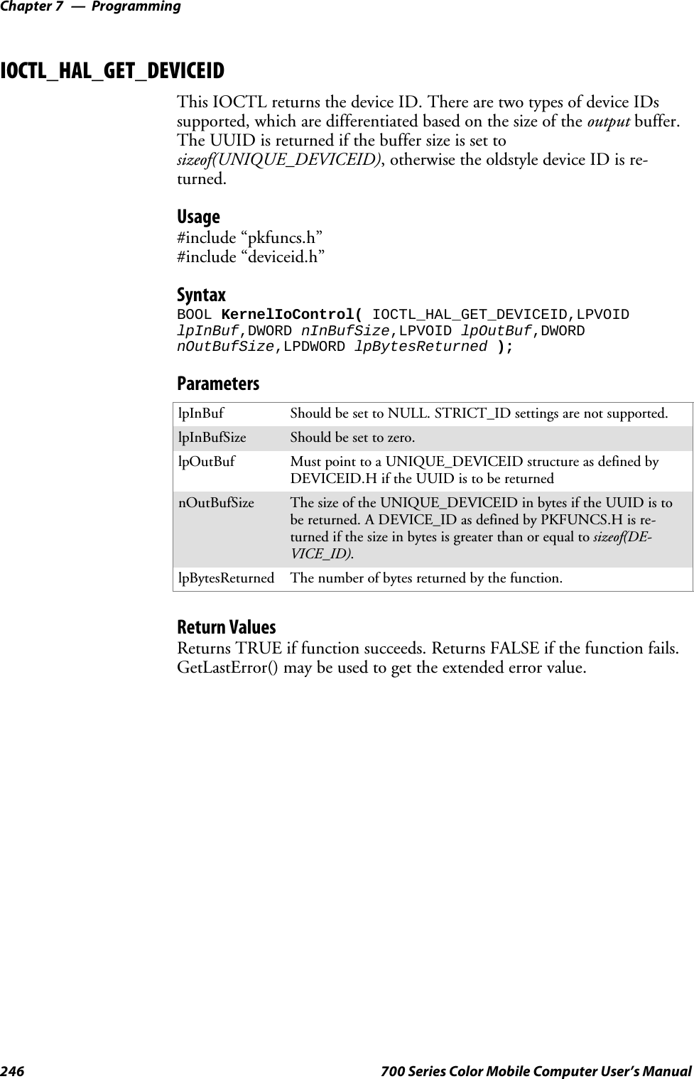
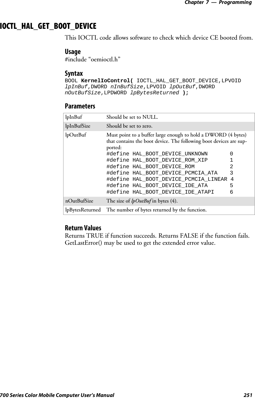
![Programming—Chapter 7247700 Series Color Mobile Computer User’s ManualIOCTL_HAL_GET_OAL_VERINFOReturns the HAL version information of the Pocket PC image.Usage#include “oemioctl.h”SyntaxBOOL KernelIoControl( IOCTL_HAL_GET_OAL_VERINFO,LPVOIDlpInBuf,DWORD nInBufSize,LPVOID lpOutBuf,DWORDnOutBufSize,LPDWORD lpBytesReturned );ParameterslpInBuf Should be set to NULL.lpInBufSize Should be set to zero.lpOutBuf Must point to a VERSIONINFO structure as defined byOEMIOCTL.H. The fields should have these values:Scboemverinfo sizeof (tagOemVerInfo);Sverinfover 1Ssig; “ITC\0”Sid; ‘N’Stgtcustomer “”Stgtplat SeaRayStgtplatversion Current build version numberStgtcputype[8]; “Intel\0”Stgtcpu “PXA255\0”;Stgtcoreversion “”Sdate Build timeStime Build datenOutBufSize ThesizeofVERSIONINFOinbytes.lpBytesReturned Returns sizeof(PVERSIONINFO).Return ValuesReturns TRUE if function succeeds. Returns FALSE if the function fails.GetLastError() may be used to get the extended error value.](https://usermanual.wiki/Intermec-Technologies/SB555-2.User-Manual-2-of-2/User-Guide-491160-Page-41.png)
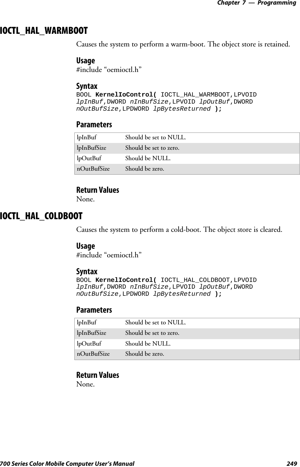
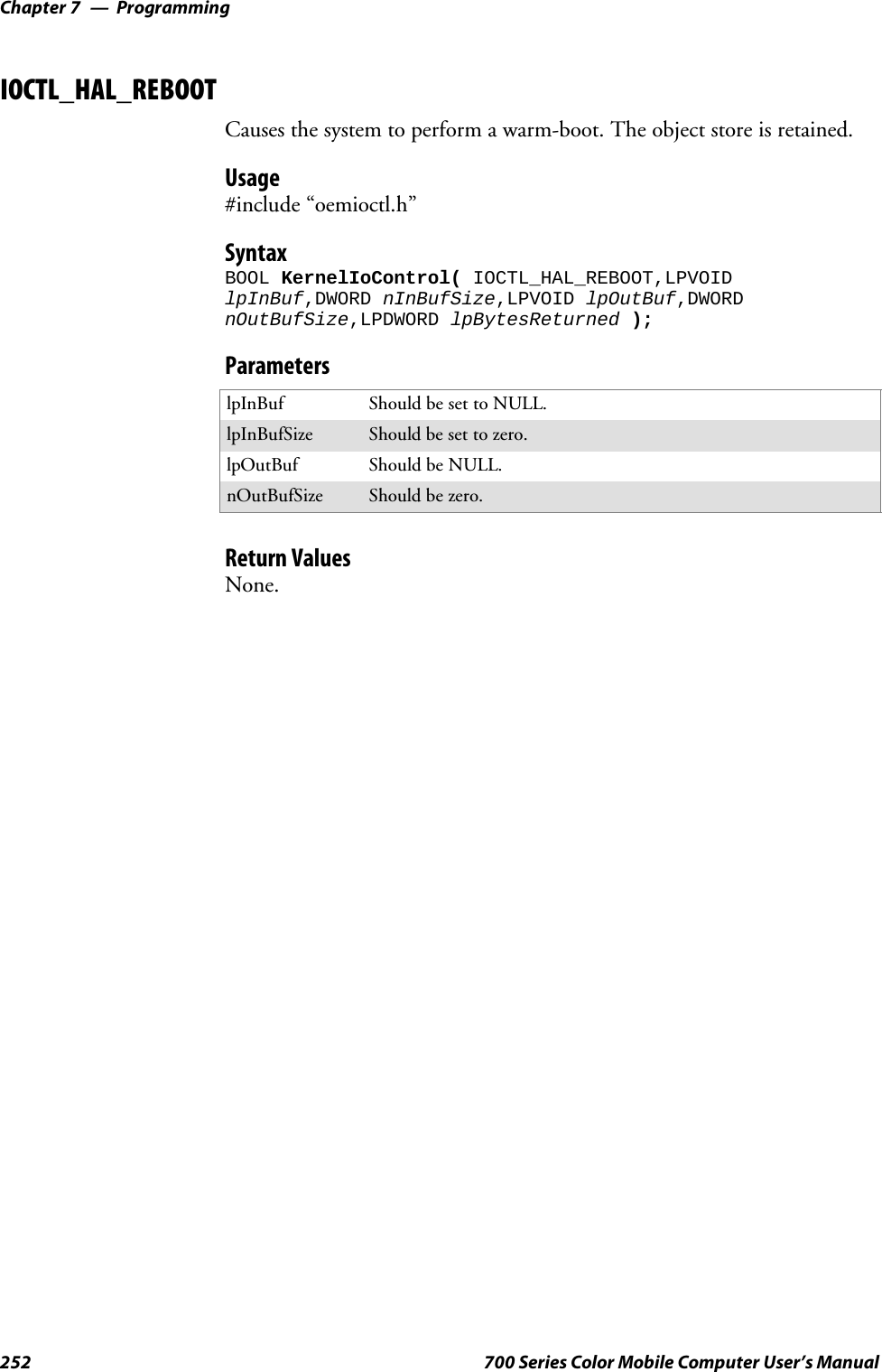
![ProgrammingChapter —7248 700 Series Color Mobile Computer User’s ManualIOCTL_HAL_GET_BOOTLOADER_VERINFOReturns the HAL version information of the Pocket PC image.Usage#include “oemioctl.h”SyntaxBOOL KernelIoControl( IOCTL_HAL_GET_OAL_VERINFO,LPVOIDlpInBuf, DWORD nInBufSize,LPVOID lpOutBuf,DWORDnOutBufSize,LPDWORD lpBytesReturned );ParameterslpInBuf Should be set to NULL.nInBufSize Should be set to zero.lpOutBuf Must point to a VERSIONINFO structure as defined byOEMIOCTL.H. The fields should have these values:Scboemverinfo Sizeof (tagOemVerInfo);Sverinfover 1Ssig; “ITC\0”Sid; ‘B’Stgtcustomer “”Stgtplat SeaRayStgtplatversion Current build version number of thebootstrap loaderStgtcputype[8]; “Intel\0”;Stgtcpu “PXA255\0”Stgtcoreversion “”Sdate Build timeStime Build datenOutBufSize ThesizeofVERSIONINFOinbytes.lpBytesReturned The number of bytes returned to lpOutBuf.Return ValuesReturns TRUE if function succeeds. Returns FALSE if the function fails.GetLastError() may be used to get the extended error value.](https://usermanual.wiki/Intermec-Technologies/SB555-2.User-Manual-2-of-2/User-Guide-491160-Page-42.png)
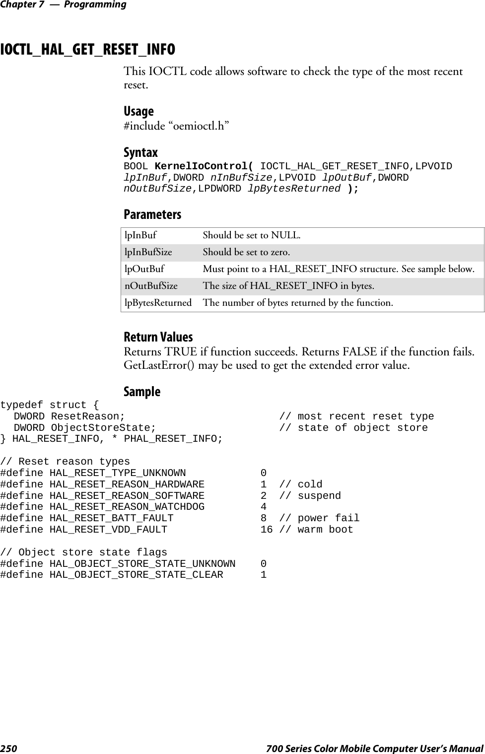
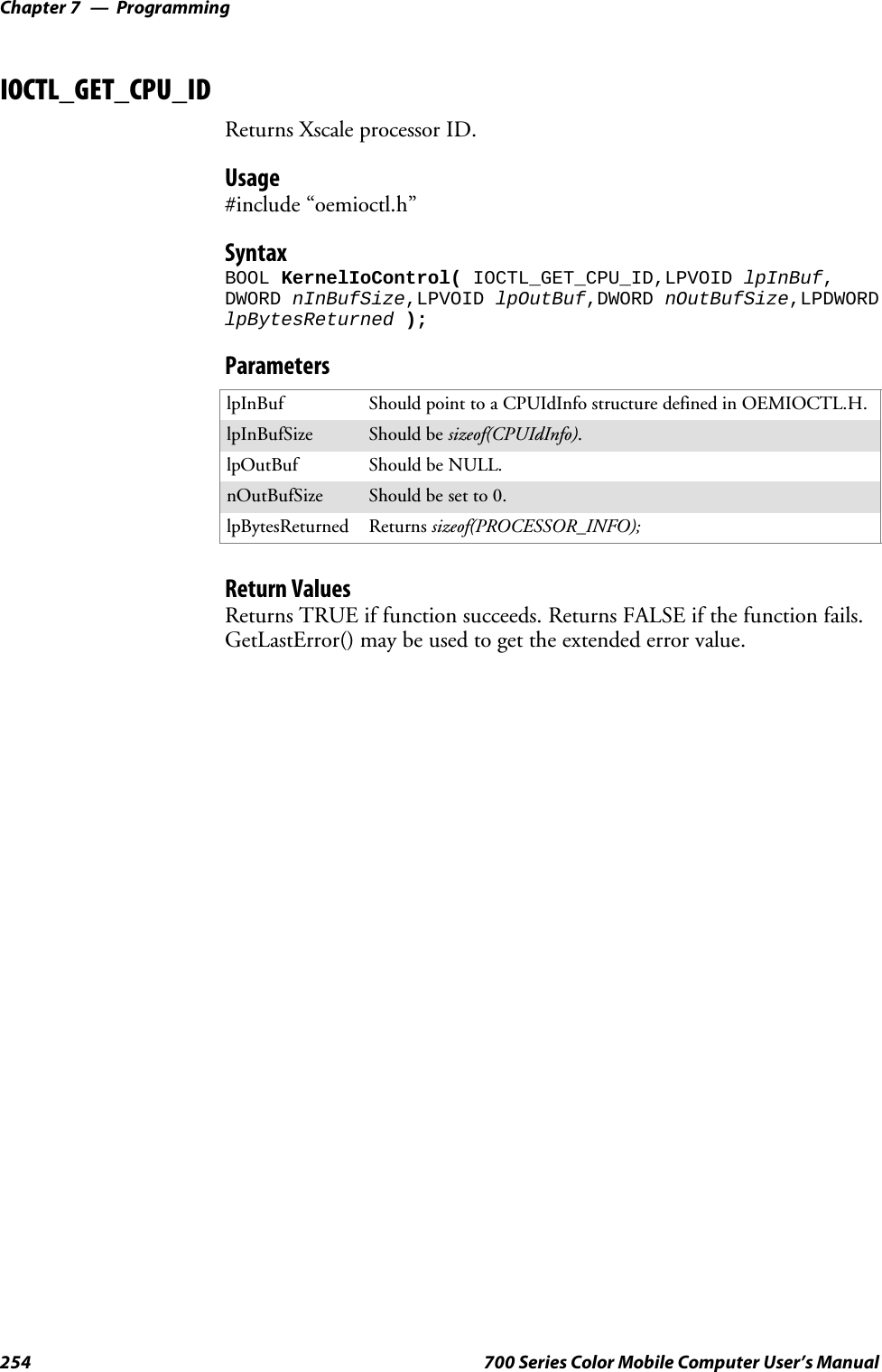
![Programming—Chapter 7253700 Series Color Mobile Computer User’s ManualIOCTL_PROCESSOR_INFORMATIONReturns processor information.Usage#include “pkfuncs.h”SyntaxBOOL KernelIoControl( IOCTL_PROCESSOR_INFORMATION,LPVOIDlpInBuf,DWORD nInBufSize,LPVOID lpOutBuf,DWORDnOutBufSize,LPDWORD lpBytesReturned );ParameterslpInBuf Should be set to NULL.nInBufSize Should be set to zero.lpOutBuf Should be a pointer to the PROCESSOR_INFO structure. ThePROCESSOR_INFO structure stores information that describesthe CPU more descriptively.typedef __PROCESSOR_INFO {WORD wVersion; // Set to value 1WCHAR szProcessorCore[40]; // “ARM\0”WORD wCoreRevision; // 4WCHAR szProcessorName[40]; // “PXA255\0”WORD wProcessorRevision; // 0WCAHR szCatalogNumber[100]; // 0WCHAR szVendor[100]; // “Intel Corporation\0”DWORD dwInstructionSet; // 0DWORD dwClockSpeed; // 400}nOutBufSize Should be set to sizeof(PROCESSOR_INFO) in bytes.lpBytesReturned Returns sizeof(PROCESSOR_INFO);Return ValuesReturns TRUE if function succeeds. Returns FALSE if the function fails.GetLastError() may be used to get the extended error value.](https://usermanual.wiki/Intermec-Technologies/SB555-2.User-Manual-2-of-2/User-Guide-491160-Page-47.png)
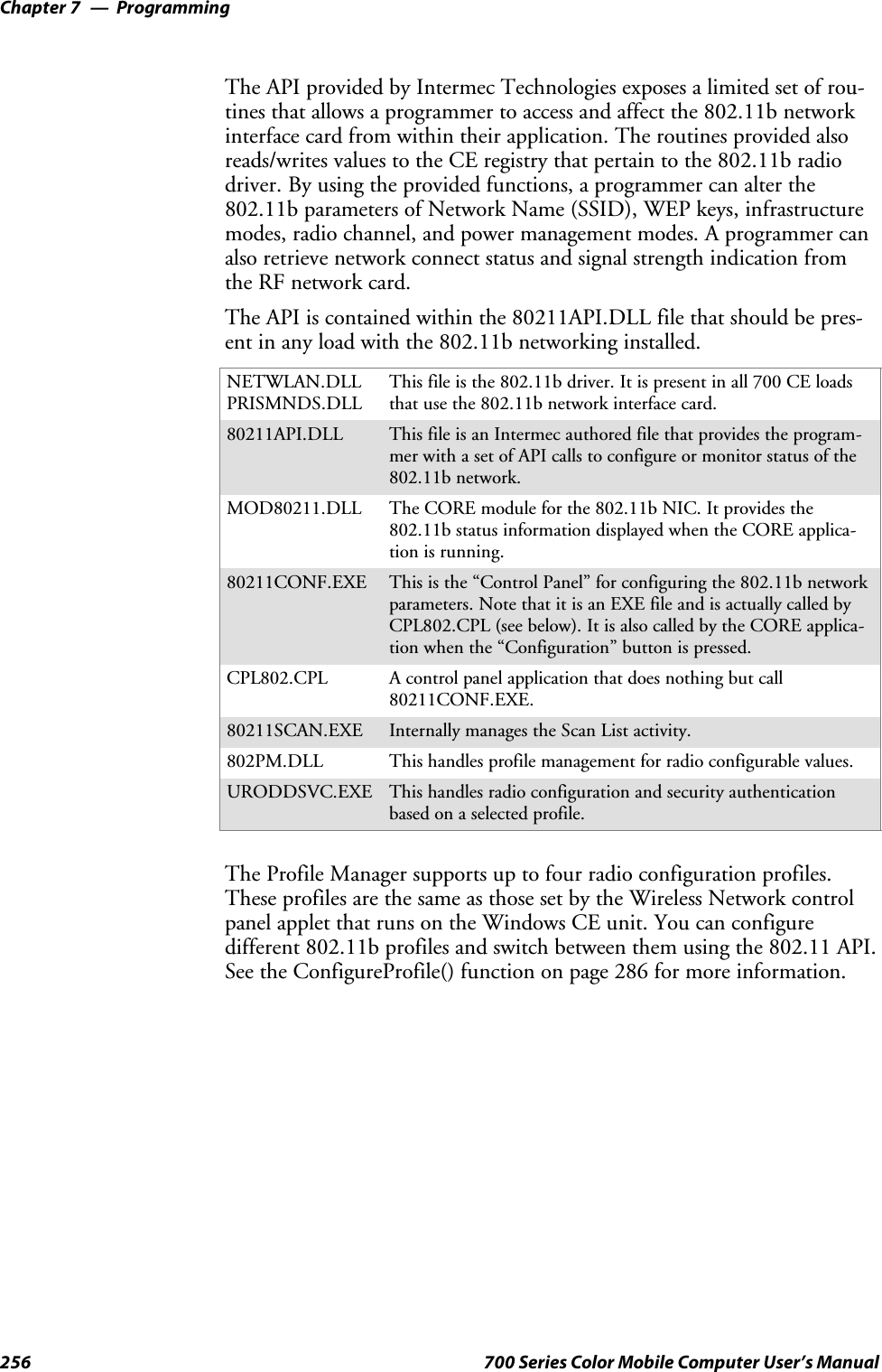
![Programming—Chapter 7255700 Series Color Mobile Computer User’s ManualNetwork Selection APIsThe Network Selection APIs change the network adapter configurationprogrammatically. Both drivers support the same IOCTL function num-bers for loading and unloading the drivers.Loading and unloading of the 802.11b driver is performed by the FWL1:device in the system by performing DeviceIOControl() calls to the driver.Loading and unloading of the driver for the built-in Ethernet adapter isperformed by the SYI1: device in the system by performingDeviceIOControl() calls to the driver.SFor loading an NDIS driver associated with an adapter, the IOCTL isIOCTL_LOAD_NDIS_MINIPORT.SFor unloading NDIS drivers associated with an adapter the IOCTL isIOCTL_UNLOAD_NDIS_MINIPORT.Example#include <winioctl.h>#include “sysio.h”void DoLoad(int nDevice) {LPTSTR devs[] = { _T(“SYI1:”), _T(“FWL1:”) };HANDLE hLoaderDev;DWORD bytesReturned;hLoaderDev = CreateFile(devs[nDevice], GENERIC_READ|GENERIC_WRITE, 0,NULL, OPEN_EXISTING, 0, NULL);if (hLoaderDev != INVALID_HANDLE_VALUE) {if (!DeviceIoControl( hLoaderDev, IOCTL_LOAD_NDIS_MINIPORT, NULL, -1, NULL, 0,&bytesReturned, NULL)){MessageBox(NULL, TEXT(“SYSIO IoControl Failed”), TEXT(“Networkloader”),MB_ICONHAND);if (hLoaderDev!=INVALID_HANDLE_VALUE) CloseHandle(hLoaderDev);hLoaderDev = INVALID_HANDLE_VALUE; // bad handle}else {CloseHandle(hLoaderDev);}}}void DoUnload(int nDevice) {LPTSTR devs[] = { _T(“SYI1:”), _T(“FWL1:”) };HANDLE hLoaderDev;DWORD bytesReturned;hLoaderDev = CreateFile(devs[nDevice], GENERIC_READ|GENERIC_WRITE, 0,NULL, OPEN_EXISTING, 0, NULL);if (hLoaderDev != INVALID_HANDLE_VALUE) {if (!DeviceIoControl( hLoaderDev, IOCTL_UNLOAD_NDIS_MINIPORT, NULL, -1, NULL, 0,&bytesReturned, NULL)){MessageBox(NULL, TEXT(“SYSIO IoControl Failed”),TEXT(“Networkloader”),MB_ICONHAND);if (hLoaderDev!=INVALID_HANDLE_VALUE) CloseHandle(hLoaderDev);hLoaderDev = INVALID_HANDLE_VALUE; // bad handle}else {CloseHandle(hLoaderDev);}}}](https://usermanual.wiki/Intermec-Technologies/SB555-2.User-Manual-2-of-2/User-Guide-491160-Page-49.png)
![ProgrammingChapter —7304 700 Series Color Mobile Computer User’s ManualRemapping the KeypadNote; Use caution when remapping the keypad. Improper remapping mayrender the keypad unusable. Data within the 700 Series Computer couldalso be lost, should any problems occur.Applications have the ability to remap keys on the 700 Color NumericKeypad and 700 Color Alphanumeric Keypad. This will allow applicationsto enable keys that would otherwise not be available, such as the [F1]function key. Also, to disable keys that should not be available, such as thealpha key because no alpha entry is required. Care should be exercisedwhen attempting to remap the keypad because improper remapping maycause the keypad to become unusable. This can be corrected by cold boot-ing the device which will cause the default keymap to be loaded again.Note that remapping the keys in this way affects the key mapping for theentire system, not just for the application that does the remapping.There are three “planes” supported for the 700 Color Numeric Keypadand Alphanumeric Keypad. Keys that are to be used in more than one shiftplane must be described in each plane.Unshifted PlaneThe unshifted plane contains values from the keypad when not pressedwith other keys, such as the following:Press the KeysNumeric Keypad Alphanumeric Keypad To Enter This1M15T59Y9Gold PlaneThe gold plane contains values from the keypad when a key is simulta-neously pressed with the [Gold] bkey on the numeric keypad or the[Gold/White] ckey on the alphanumeric keypad, such as the following:Press the KeysNumeric Keypad Alphanumeric Keypad To Enter This[Gold] b1[Gold/White] ce Send[Gold] b5[Gold/White] cC A3[Gold] b9[Gold/White] cP PgDn](https://usermanual.wiki/Intermec-Technologies/SB555-2.User-Manual-2-of-2/User-Guide-491160-Page-98.png)
![Programming—Chapter 7305700 Series Color Mobile Computer User’s ManualAlpha (Blue) PlaneThe alpha plane contains values from the keypad when the keypad hasbeen placed in alpha mode by pressing the blue alpha key, such as the fol-lowing:Press the KeysNumeric Keypad Alphanumeric Keypad To Enter This[Alpha] F1[Alpha] FgCaps[Alpha] F5[Alpha] FJj[Alpha] F9[Alpha] FWwKey ValuesKey values for each plane are stored in the registry. All units ship with adefault key mapping already loaded in the registry. Applications that wishto change the default mapping need to read the appropriate key from theregistry into an array of Words, modify the values required and then writethe updated values back into the registry. The registry access can be donewith standard Microsoft API calls, such as RegOpenKeyEx(), RegQuery-ValueEx(), and RegSetValueEx().Numeric KeypadFor the 700 Color Numeric Keypad, the following registry keys containthe plane mappings:SThe unshifted plane mapping can be found in the registry at:HKEY_LOCAL_MACHINE\HARDWARE\DEVICEMAP\KEYBD\VkeySThe gold plane mapping can be found in the registry at:HKEY_LOCAL_MACHINE\HARDWARE\DEVICEMAP\KEYBD\VkeyGoldSThe alpha plane mapping can be found in the registry at:HKEY_LOCAL_MACHINE\HARDWARE\DEVICEMAP\KEYBD\VkeyAlphaAlphanumeric KeypadFor the 700 Color Alphanumeric Keypad, the following registry keys con-tain the plane mappings:SThe unshifted plane mapping can be found in the registry at:HKEY_LOCAL_MACHINE\HARDWARE\DEVICEMAP\KEYBD\ALPHA\VkeySThe gold plane mapping can be found in the registry at:HKEY_LOCAL_MACHINE\HARDWARE\DEVICEMAP\KEYBD\ALPHA\VkeyGoldSThe alpha plane mapping can be found in the registry at:HKEY_LOCAL_MACHINE\HARDWARE\DEVICEMAP\KEYBD\ALPHA\VkeyAlpha](https://usermanual.wiki/Intermec-Technologies/SB555-2.User-Manual-2-of-2/User-Guide-491160-Page-99.png)
![ProgrammingChapter —7306 700 Series Color Mobile Computer User’s ManualHow Key Values Are Stored in RegistryTo know which fields to update in the registry, you must know what ScanCodes are assigned to each physical key (see the “Keypad Scan Codes andMeanings” table on the next page). The Scan Code is used at the lowestlevel of the system to let the keypad driver know which physical key hasbeen pressed. The keypad driver takes that scan code and looks it up in atable (a copy of the one stored in the registry) to determine which valuesto pass on to the operating system.Each registry key is just an array that describes to the keypad driver whatvalue needs to be passed for each physical key. The key values are indexedby the scan code, this is a zero-based index. For example in the unshiftedplane, the [4] key has a scan code of 0x06. This means that the seventhword under the “Vkey” registry key will have the value for the [4] key.Taking a sample of the “Vkey” registry key shows the following values:00,00,0B,05,02,03,C1,07,04,03,BE,00,34,00,00,00,. . .The value is 34,00. The values are in reverse byte order because that is theway the processor handles data. When writing an application, nothingneeds to be done to swap the bytes, as this will happen automatically whenthe data is read into a byte value. This is something you just need to beaware of this when looking at the registry. Knowing this, we can see thatthe value that the keypad driver will pass to the system is a hex 34. Look-ing that up on an UNICODE character chart, we see that it maps to a “4”.If you wanted the key, labeled “4”, to output the letter “A” instead, youwould need to change the seventh word to “41” (the hexadecimal repre-sentation of “A” from the UNICODE chart), then put the key back intothe registry.Note: Do not remap scan codes 0x01, 0x41, 0x42, 0x43, 0x44. Remap-ping these scan codes could render your 700 Series Computer unusableuntil a cold-boot is performed.If you wish to disable a certain key, remap its scan code to 0x00.Change NotificationJust changing the registry keys will not immediately change the keymappings. To notify the keypad driver that the registry has been updated,signal the “ITC_KEYBOARD_CHANGE” named event using theCreateEvent() API.Advanced Keypad RemappingIt is also possible to map multiple key presses to one button and to mapnamed system events to a button. The multiple key press option could beuseful to cut down on the number of keys needed to press in a given situa-tion or to remap which key behaves like the action key. Mapping events toa button could be useful to change which buttons will fire the scanner,control volume, and allow for suspending and resuming the device. If youneed help performing one of these advanced topics please contact IntermecTechnical Support.](https://usermanual.wiki/Intermec-Technologies/SB555-2.User-Manual-2-of-2/User-Guide-491160-Page-100.png)
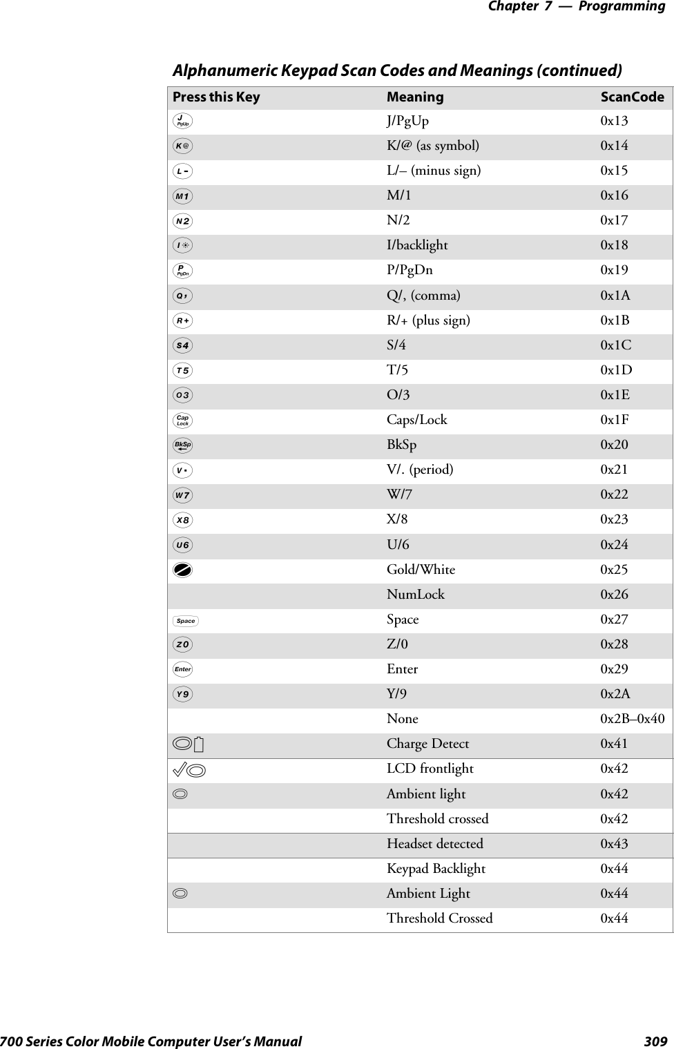
![Programming—Chapter 7307700 Series Color Mobile Computer User’s ManualScan CodesAt the lowest driver level, the 700 Color Numeric Keypad and the 700Color Alphanumeric Keypad identifies keys as scan codes. These scancodes are sent via the keypad microcontroller, and cannot be changedwithout modifying the keypad firmware.Numeric KeypadThe following scan codes pertain to the 700 Color Numeric keypad:Numeric Keypad Scan Codes and MeaningsPressthisKey Meaning ScanCodeReserved 0x00II/O button 0x01Scanner Handle Trigger 0x02Scanner Left 0x03Scanner Right 0x0444/GHI/A2 0x06None 0x07LLeft arrow/Back Tab 0x08None 0x09KBkSp// (forward slash) 0x0Ab[Gold] key 0x0BNone 0x0CEEsc/– (minus sign) 0x0DDDown arrow/Volume decrease 0x0E11/Caps/Send 0x0F77/PQRS/PgUp 0x10F[Alpha] key 0x11None 0x12UUp arrow/Volume increase 0x13RRight arrow/Tab 0x1422/ABC/End 0x1588/TUV/* (asterisk) 0x1600/Win 0x1755/JKL/A3 0x18None 0x19AAction/+ (plus symbol) 0x1A33/DEF/backlight 0x1B99/WXYZ/PgDn 0x1C](https://usermanual.wiki/Intermec-Technologies/SB555-2.User-Manual-2-of-2/User-Guide-491160-Page-101.png)
![ProgrammingChapter —7310 700 Series Color Mobile Computer User’s ManualSample View of Registry KeysThe following is a sample view of the current default key mapping for the700 Color Numeric Keypad. See the registry on your device for the latestkey mappings.[HKEY_LOCAL_MACHINE\HARDWARE\DEVICEMAP\KEYBD]”ResumeMask”=dword:7”Vkey”=hex: 00,00,0B,05,02,03,C1,07,04,03,BE,00,34,00,00,00,\25,00,00,00,08,00,03,02,00,00,1B,00,28,00,31,00,\37,00,01,02,00,00,26,00,27,00,32,00,38,00,30,00,\35,00,00,00,01,03,33,00,39,00,0D,00,36,00,00,00,\00,00,00,00,00,00,00,00,00,00,00,00,00,00,00,00,\00,00,00,00,00,00,00,00,00,00,00,00,00,00,00,00,\00,00,00,00,00,00,00,00,00,00,00,00,00,00,00,00,\00,00,00,00,00,00,00,00,00,00,00,00,00,00,00,00,\00,00,07,05,01,05,03,05,02,05”VkeyGold”=hex: 00,00,0B,05,02,03,C1,07,04,03,BE,00,34,00,00,00,\09,01,00,00,BF,00,03,02,00,00,BD,00,75,00,72,00,\21,00,01,02,00,00,76,00,09,00,73,00,38,01,5B,00,\35,00,00,00,BB,01,09,05,22,00,32,01,36,00,00,00,\00,00,00,00,00,00,00,00,00,00,00,00,00,00,00,00,\00,00,00,00,00,00,00,00,00,00,00,00,00,00,00,00,\00,00,00,00,00,00,00,00,00,00,00,00,00,00,00,00,\00,00,00,00,00,00,00,00,00,00,00,00,00,00,00,00,\00,00,07,05,01,05,03,05,02,05”VkeyAlpha”=hex: 00,00,0B,05,02,03,C1,07,04,03,BE,00,47,00,00,00,\25,00,00,00,08,00,03,02,00,00,1B,00,28,00,02,02,\50,00,01,02,00,00,26,00,27,00,41,00,54,00,20,00,\4A,00,00,00,01,03,44,00,57,00,0D,00,4D,00,00,00,\00,00,00,00,00,00,00,00,00,00,00,00,00,00,00,00,\00,00,00,00,00,00,00,00,00,00,00,00,00,00,00,00,\00,00,00,00,00,00,00,00,00,00,00,00,00,00,00,00,\00,00,00,00,00,00,00,00,00,00,00,00,00,00,00,00,\00,00,07,05,01,05,03,05,02,05](https://usermanual.wiki/Intermec-Technologies/SB555-2.User-Manual-2-of-2/User-Guide-491160-Page-104.png)
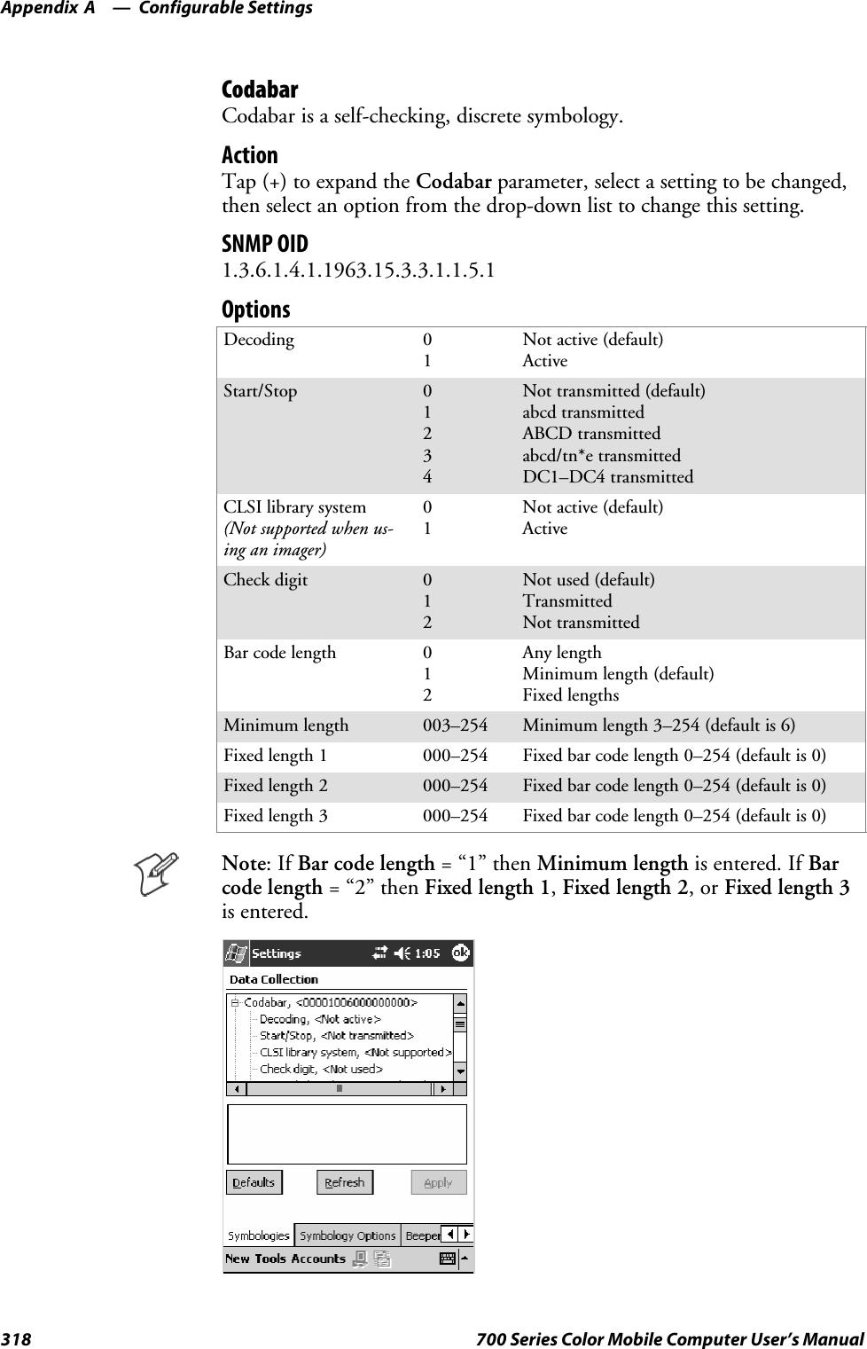
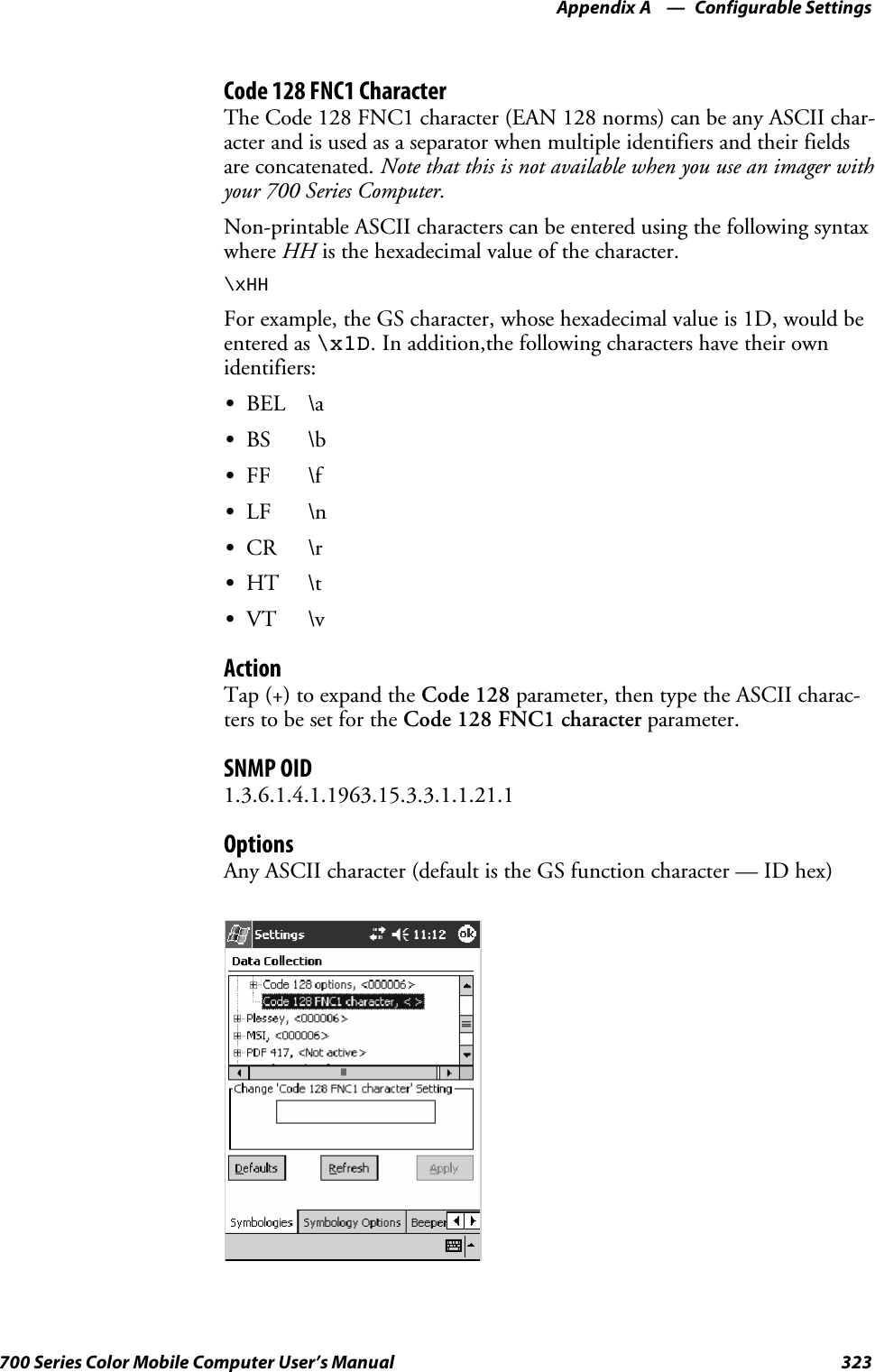
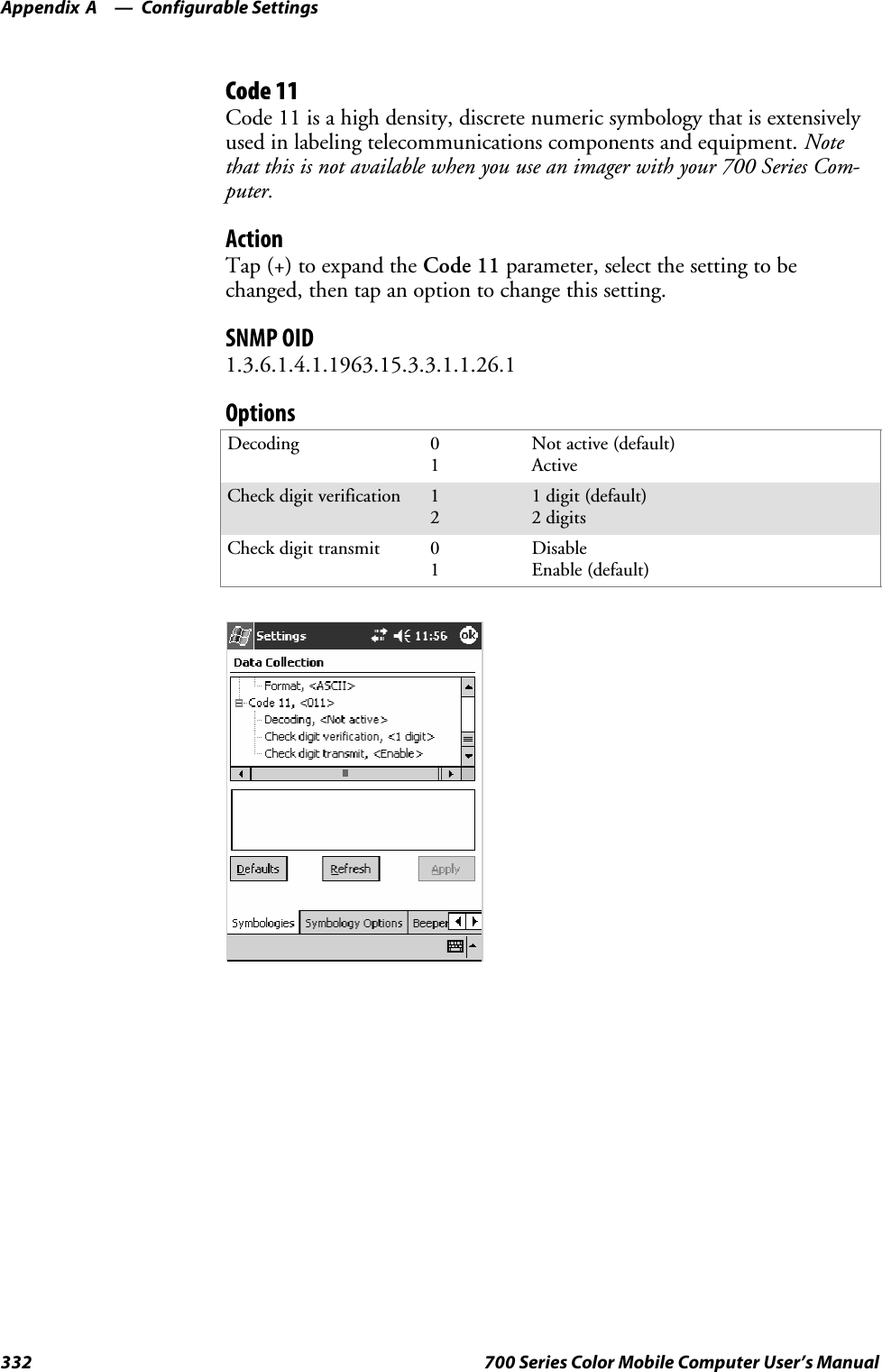
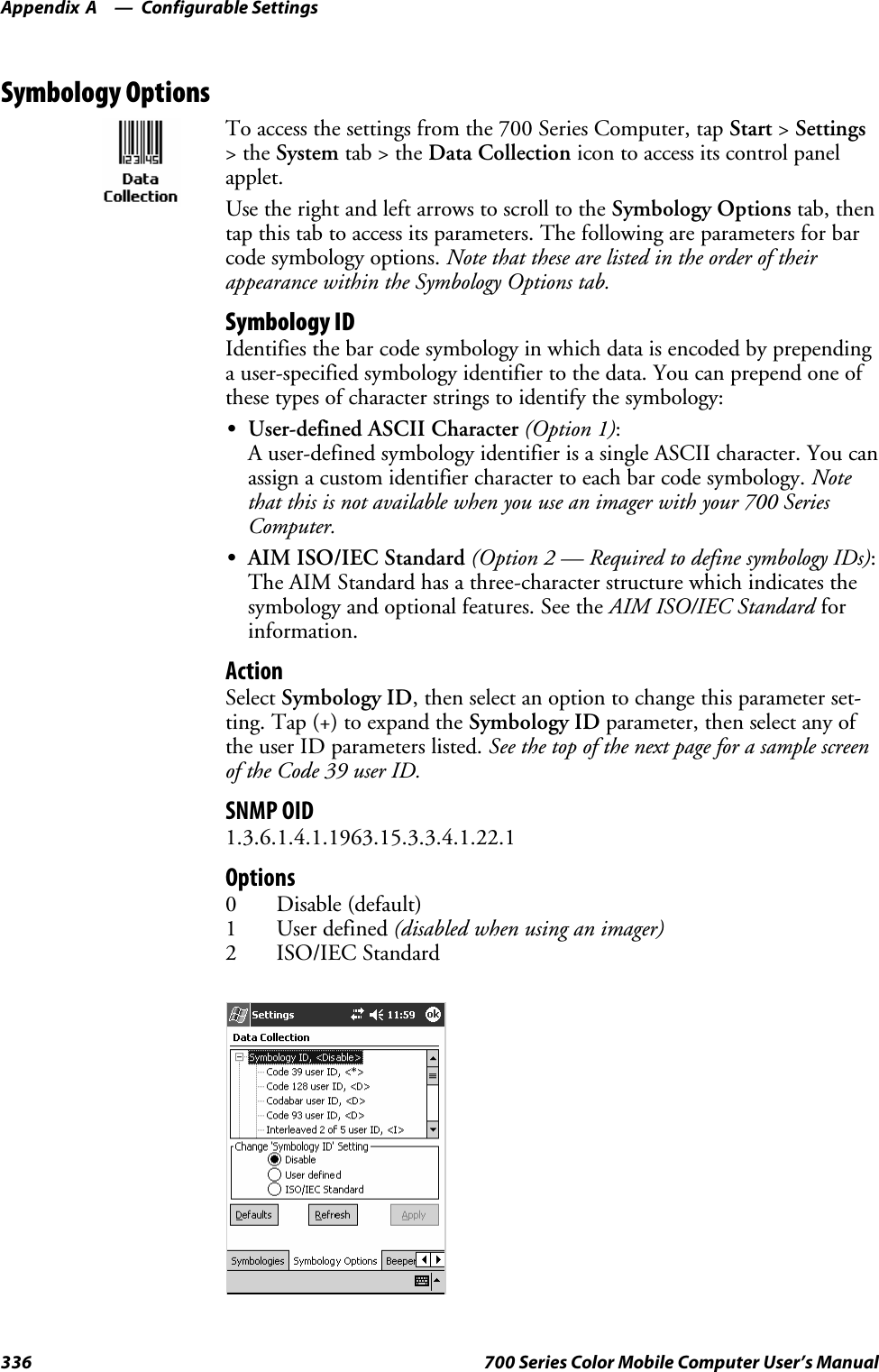
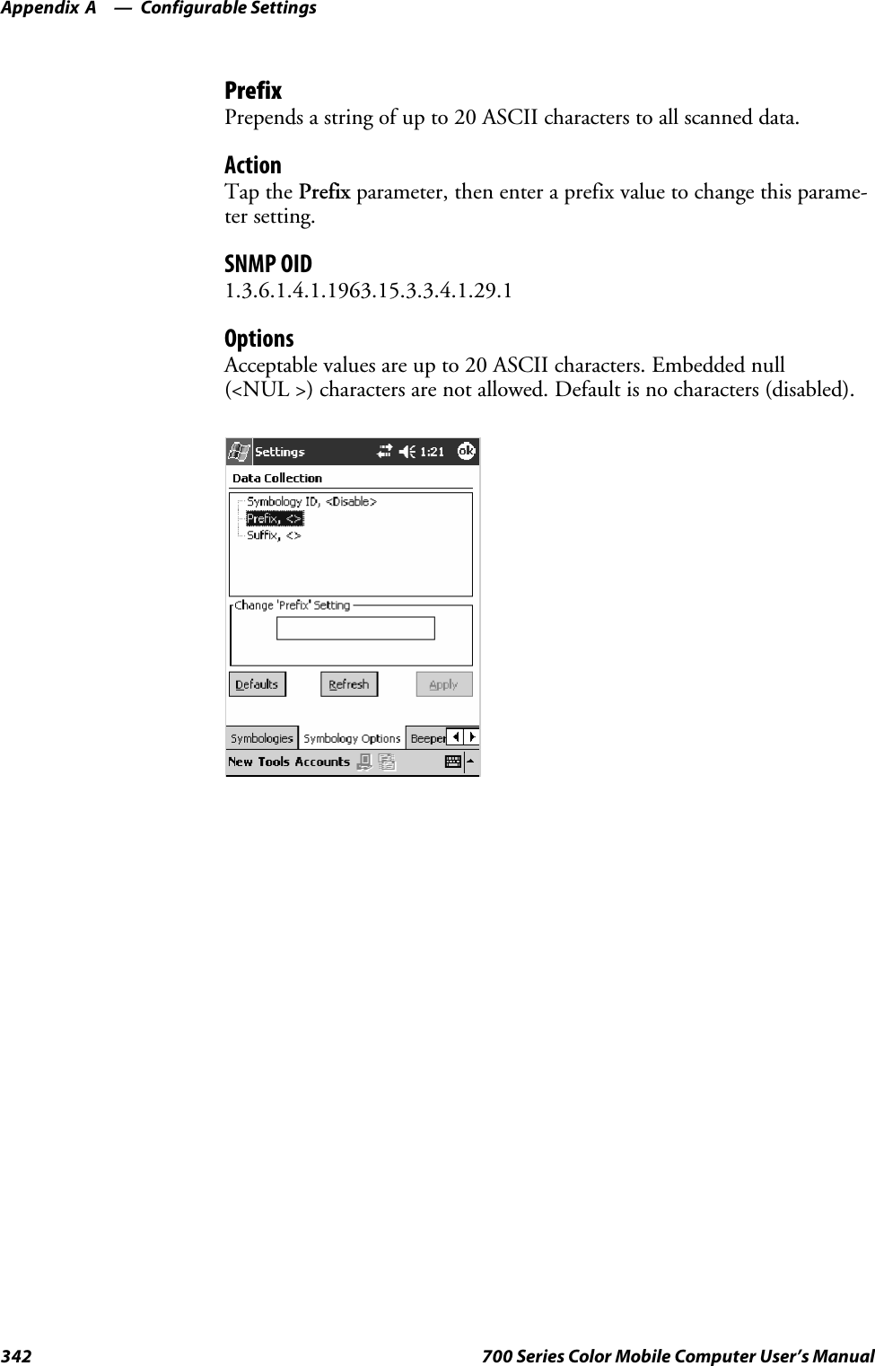
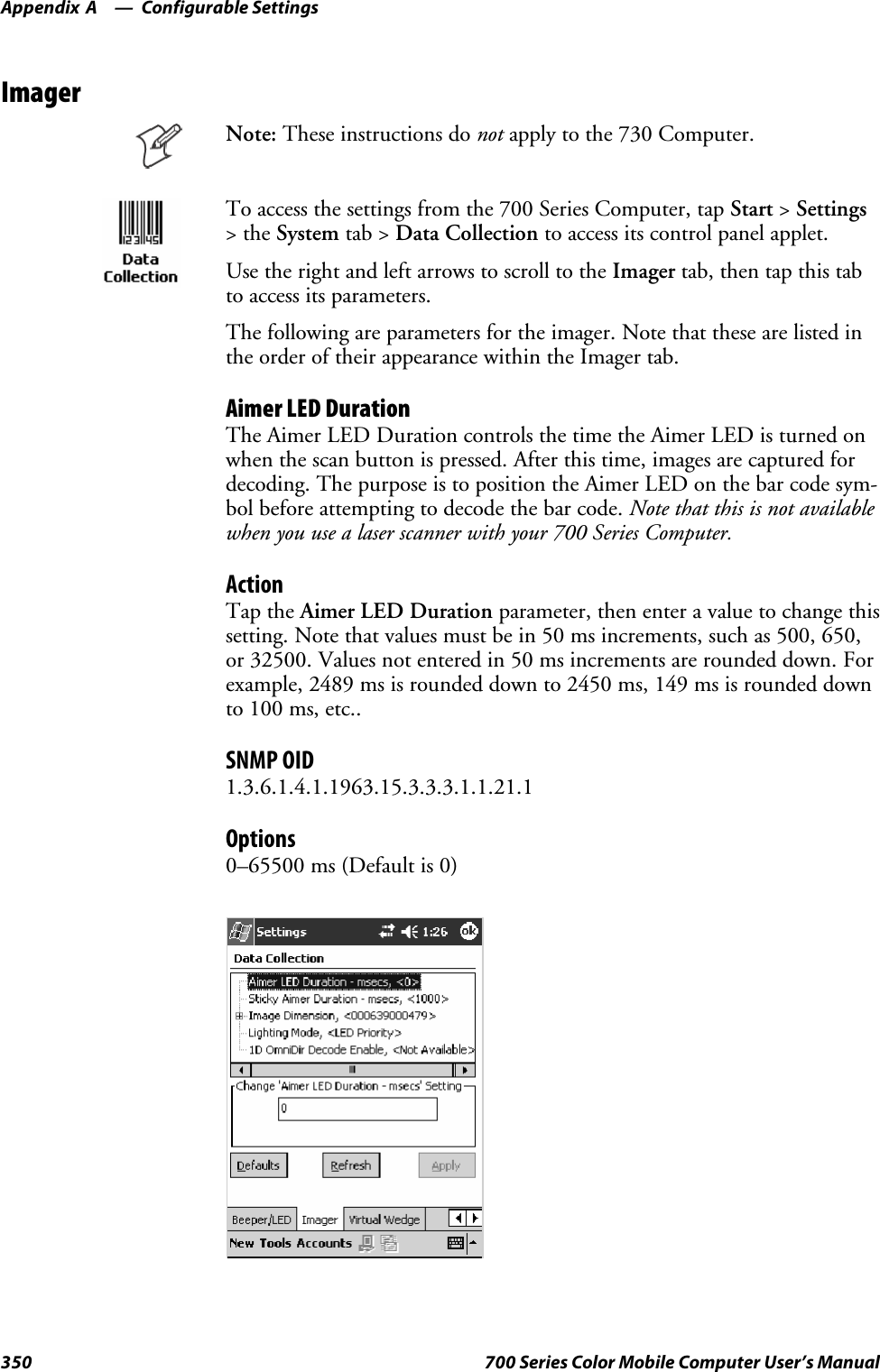
![Configurable SettingsAppendix —A322 700 Series Color Mobile Computer User’s ManualCode 128 OptionsSet the following for the Code 128 parameter. Note that the EAN 128 ]C1and CIP 128 French Pharmaceutical options are not available when you usean imager with your 700 Series Computer.ActionTap (+) to expand the Code 128 Options parameter, select a setting, thenselect an option to change this setting.SNMP OIDNone.OptionsEAN 128 ]C1 Identifier(Not supported when using animager)01Remove (default)IncludeCIP 128 French Pharmaceutical(Not supported when using animager)01Not active (default)ActiveBar code length 01Any length (default)Minimum lengthMinimum length 001–254 Minimum length 1–254 (default is 6)This illustration is from a 700 Series Computer using a laser scanner.](https://usermanual.wiki/Intermec-Technologies/SB555-2.User-Manual-2-of-2/User-Guide-491160-Page-116.png)

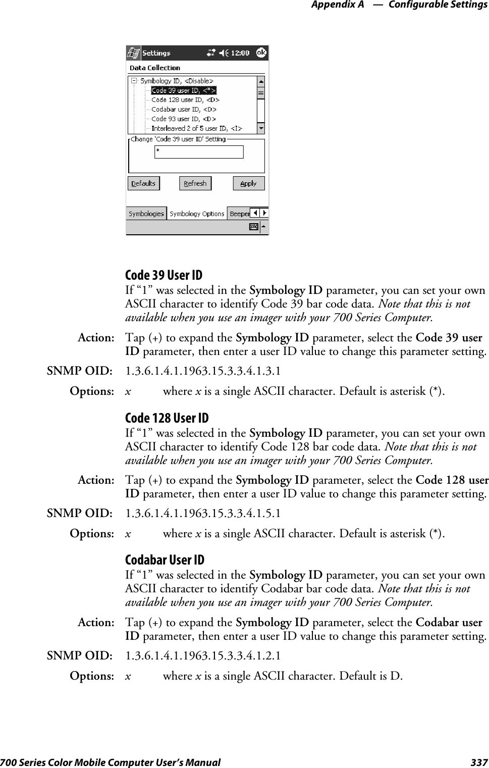
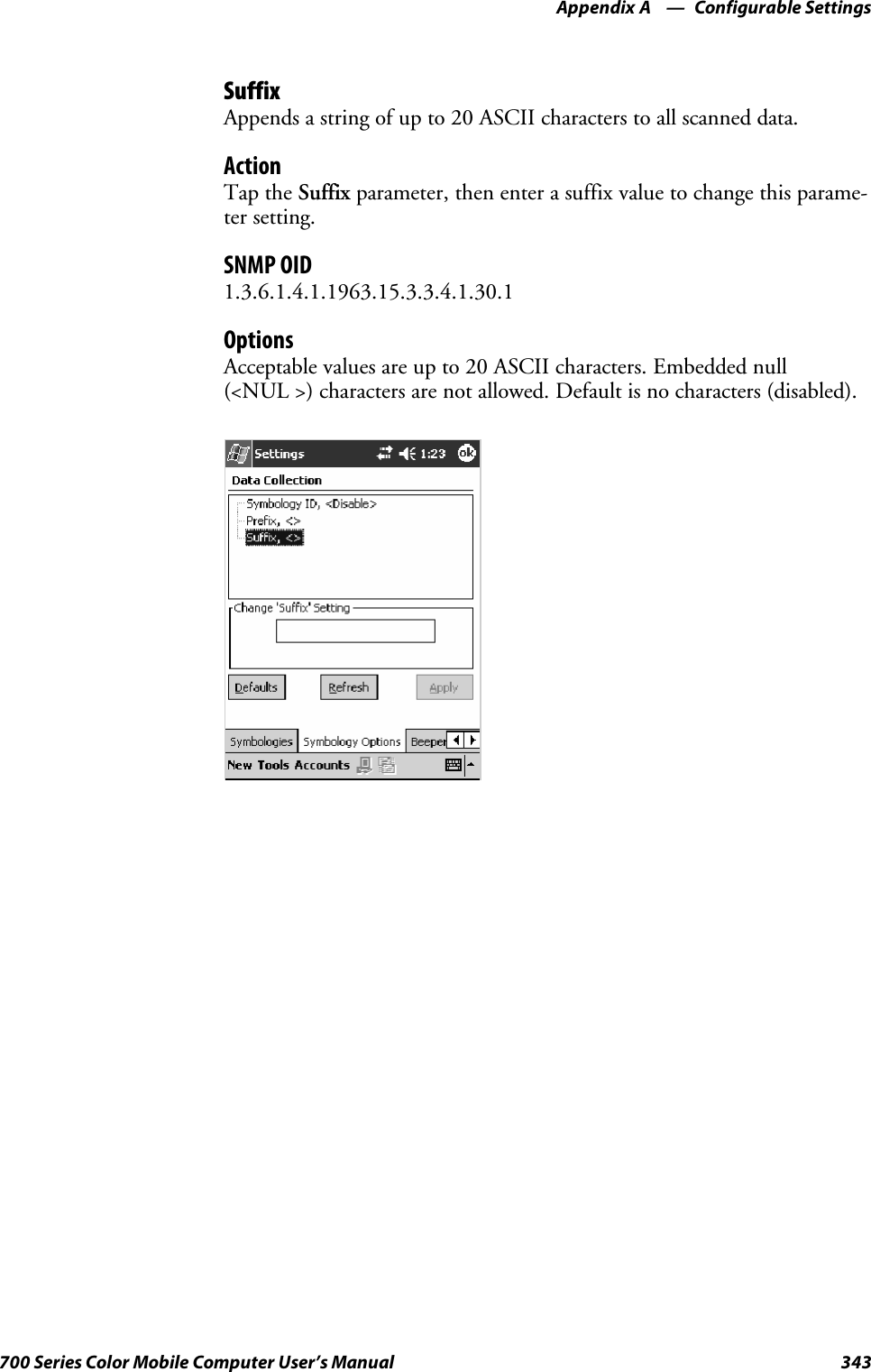
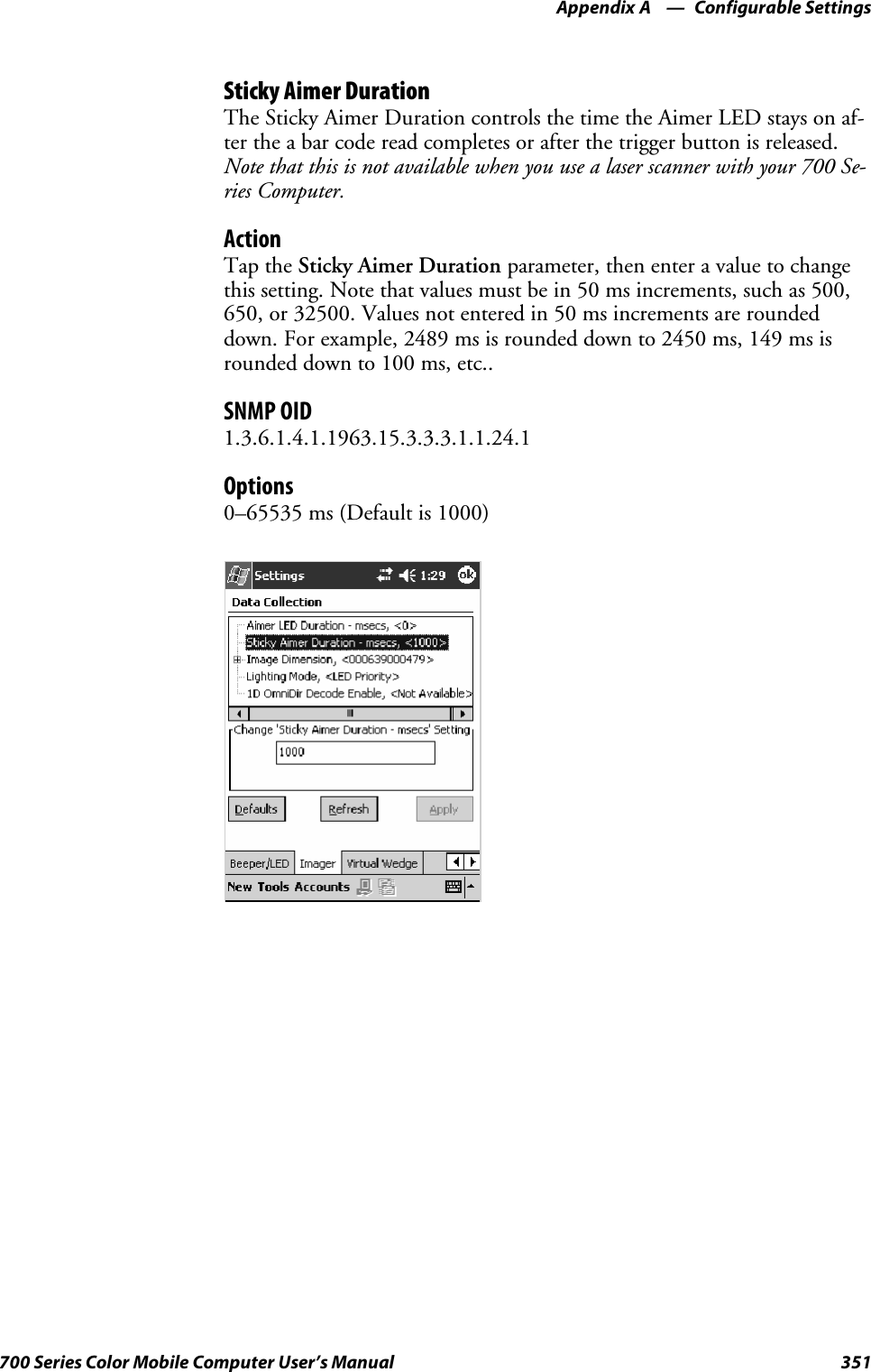
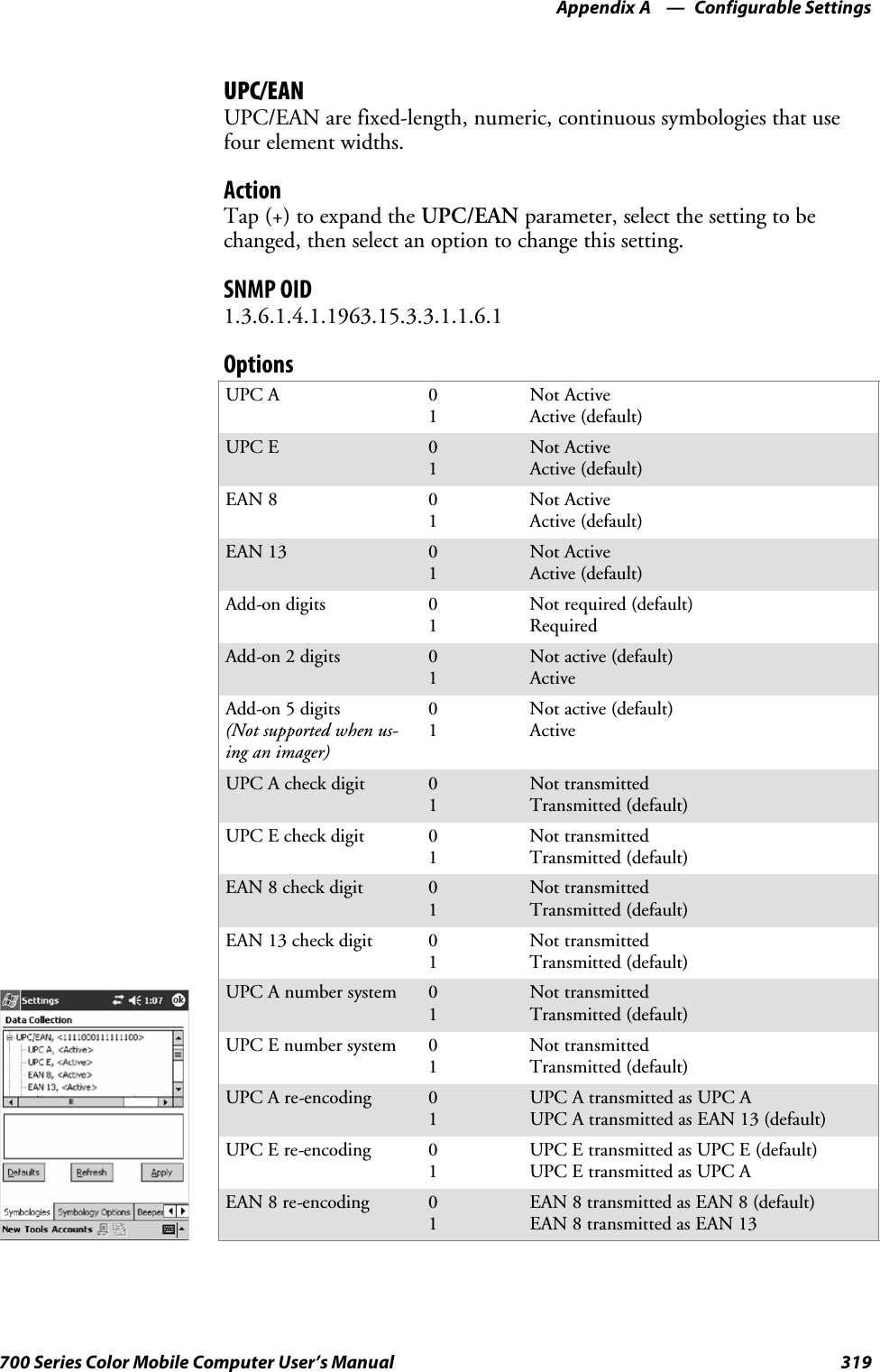
![Configurable SettingsAppendix —A382 700 Series Color Mobile Computer User’s ManualWakeup MaskFrom the 700 Series Computer, tap Start >Settings >theSystem tab >Utilities >theWakeup Mask tab to access the Wakeup Mask control pan-el applet.This applet programs three scanner buttons and the A1 and A2 applicationkeys to be “wakeup” or resume keys. That is, to prompt the 700 SeriesComputer to “wake up” or resume activity after going to “sleep” as a resultof being inactive after a length of time. This information will remain be-tween warm and cold boots.Check the appropriate box, then tap ok to apply your settings.Based on your setting, do the following to ”wake up” the 700 Series Com-puter.If you select:Then do this onNumeric KeyboardThen do this onAlphanumeric KeyboardMiddle Scanner Button Squeeze the button on the Scan Handle Squeeze the button on the Scan HandleLeft Scanner Button Squeeze the left scanner button Squeeze the left scanner buttonRight Scanner Button Squeeze the right scanner button Squeeze the right scanner buttonGOLD+A1(Application1) Press [Gold] ba Press [Gold/White] cAGOLD+A2(Application2) Press [Gold] b4 Press [Gold/White] cB](https://usermanual.wiki/Intermec-Technologies/SB555-2.User-Manual-2-of-2/User-Guide-491160-Page-176.png)
![Configurable SettingsAppendix —A410 700 Series Color Mobile Computer User’s ManualUsing Reader CommandsAfter the 700 Series Computer is connected to your network, you can sendthe 700 Series Computer a reader command from an application to per-form a task, such as changing the time and date. Some reader commandstemporarily override the configuration settings and some change the con-figuration settings.Change ConfigurationThe Change Configuration command must precede any configurationcommand. If you enter a valid string, the 700 Series Computer configura-tion is modified and the computer emits a high beep. To send the ChangeConfiguration command through the network, use the $+ [command]syntax where command is the two-letter command syntax for the configu-ration command followed by the value to be set for that command.You can also make changes to several different commands by using the$+ [command]...[command n] syntax. There are seven configurationcommand settings that can be changed in this way. See each command forinformation on respective acceptable “data” values.Command SyntaxAudio Volume BVdataAutomatic Shutoff EZdataBacklight Timeout DFdataKey Clicks KCdataVirtual Wedge Grid AFdataVirtual Wedge Postamble AEdataVirtual Wedge Preamble ADdataNote: See pages 356 and 358 for more information about the VirtualWedge Postamble and Virtual Wedge Preamble commands.Example 1To change the Beep Volume to Off, you can send this string to the 700Series Computer through the network: $+BV0where:$+ Indicates Change Configuration.BV Specifies the Audio Volume parameter.0Specifies a value of Off.Example 2To change the Beep Volume to Very Quiet and the Virtual Wedge Gridto 123: $+BV1AF123where:$+ Indicates Change ConfigurationBV1 Specifies Audio Volume, set to Very Quiet (1)AF123 Specifies Virtual Wedge Grid, set to a value of 123.](https://usermanual.wiki/Intermec-Technologies/SB555-2.User-Manual-2-of-2/User-Guide-491160-Page-204.png)


![Bar Code SymbologiesAppendix —B420 700 Series Color Mobile Computer User’s ManualCode 128Code 128 (C128) is one of the newest symbologies used by the retail andmanufacturing industries. It responds to the need for a compact alphanu-meric bar code symbol that could encode complex product identification.The fundamental requirement called for a symbology capable of beingprinted by existing data processing printers (primarily dot-matrix printers)that produce daily, work-in-progress, job, and product traceability docu-ments. The ability to print identification messages between 10 and 32characters long, on existing forms and labels deemed an important require-ment.Code 128 uniquely addresses this need as the most compact, complete,alphanumeric symbology available.Additionally, the Code 128 design with geometric features, improves scan-ner read performance, does self-checking, and provides data message man-agement function codes.Code 128 encodes the complete set of 128 ASCII characters without ad-ding extra symbol elements. Code 128 contains a variable-length symbolo-gy and the ability to link one message to another for composite messagetransmission. Code 128, being a double-density field, provides two numer-ic values in a single character.Code 128 follows the general bar code format of start zone, data, checkdigit, stop code, and quiet zone. An absolute minimum bar or space di-mension of nine mils (0.010 inch minimum nominal ±0.001 inch toler-ance) must be maintained.Characters in Code 128 consist of three bars and three spaces so that thetotal character set includes three different start characters and a stop char-acter.UCC/EAN-128 Shipping Container Labeling is a versatile tool that canease movement of products and information. The Shipping Container La-beling bar code can take any form and usually has meaning only within thecompany or facility where applied.Because this random data can get mistaken later for an industry standardcode format, the UCC and EAN chose a symbology uniquely identifiedfrom these other bar codes. This standard is for maximum flexibility, tohandle the diversity of distribution in global markets by cost efficiency.The UCC/EAN-128 Container Labeling specification calls for a FUNC1to immediately follow the bar code’s start character. FUNC1 also followsany variable-length application field. The specification also calls for thecomputer to send “]C1” for the first FUNC1. The specification requiresthat the computer send a “<GS>” (hex 1D) for subsequent FUNC1 codesin the bar code.Because “<GS>” is not compatible with computer emulation data streams,the Uniform Code Council has been asked to change the specification.This change is made to send the same three character sequence “]C1” toidentify the embedded FUNC1 codes.](https://usermanual.wiki/Intermec-Technologies/SB555-2.User-Manual-2-of-2/User-Guide-491160-Page-214.png)


![Index428 700 Series Color Mobile Computer User’s ManualClasses and FunctionsAadd_registry_section, [AddReg]flags, 216registry_root_string, 216value_name, 216AddReg, [DefaultInstall], 212[AddReg], add_registry_sectionflags, 216registry_root_string, 216value_name, 216AddWep(), 275AppName, [CEStrings], 209BBuildMax, [CEDevice], 210BuildMin, [CEDevice], 210C[CEDevice]BuildMax, 210BuildMin, 210ProcessorType, 210UnsupportedPlatforms, 210VersionMax, 210VersionMin, 210CESelfRegister, [DefaultInstall], 212CESetupDLL, [DefaultInstall], 212CEShortcuts, [DefaultInstall], 212[CEShortcuts], shortcut_list_sectionshortcut_filename, 217shortcut_type_flag, 217target_file/path, 217target_file_path, 217CESignature[SourceDiskNames], 212[Version], 208[CEStrings]AppName, 209InstallDir, 209CloseHandle()DTR printing, 188, 189IrDA printing, 182NPCP printing, 183, 184ConfigureProfile(), 286Copyfiles, [DefaultInstall], 212[CopyFiles], file_list_sectiondestination_filename, 215flags, 215source_filename, 215CreateEvent(), 306CreateFile()DTR printing, 188, 189IrDA printing, 182NPCP printing, 183, 184D[DefaultInstall]AddReg, 212CESelfRegister, 212CESetupDLL, 212CEShortcuts, 212Copyfiles, 212DeregisterDevice(), 183DTR printing, 188[DestinationDirs], file_list_section, 214DeviceIOControl(), 255DTR printing, 188NPCP printing, 183DeviceIoControl(), NPCP printing, 184, 185disk_ordinal, [SourceDiskNames], 212DllRegisterServer, 212DllUnregisterServer, 212EEnableSuppLogging(), 298EnableWep(), 276EnableZeroConfig(), 287EncryptionStatus(), 277EncryptWepKeyForRegistry(Deprecated), 300Ffile_list_section[CopyFiles]destination_filename, 215flags, 215source_filename, 215[DestinationDirs], 214filename, [SourceDiskFiles], 213GGetAssociationStatus(), 260GetAuthenticationMode(), 261GetBSSID(), 262GetCCXStatus(), 274GetCurrentDriverName(), 296GetDiversity(), 263GetLinkSpeed(), 264GetMac(), 265GetMedia(Deprecated), 300GetMedium(Deprecated), 300GetNetworkMode(), 266GetNetworkType(), 267GetNicStats(Deprecated), 300GetPowerMode(), 269GetRadioIpAddress(), 273GetRSSI(), 270GetRTSThreshold(Deprecated), 300GetSSID(), 268GetTXPower(), 271GetWepStatus(), 272](https://usermanual.wiki/Intermec-Technologies/SB555-2.User-Manual-2-of-2/User-Guide-491160-Page-222.png)
![Index429700 Series Color Mobile Computer User’s ManualIInstallDir, [CEStrings], 209isDHCPEnabled(), 294isOrinoco(), 289isSupplicantRunning(), 290isZeroConfigEnabled(), 288KKernelIoControl(), 239NNLEDGetDeviceInfo, 302NLEDSetDevice, 302OOSVERSIONINFO.dwBuildNumber, 210OSVERSIONINFO.dwVersionMajor, 210OSVERSIONINFO.dwVersionMinor, 210PProcessorType, [CEDevice], 210Provider, [Version], 208RRadioConnect(), 257RadioDisassociate(), 259RadioDisconnect(), 258ReadFile(), NPCP printing, 183RegFlushKey(), 123, 225RegisterDevice(), 183DTR printing, 188RegOpenKeyEx(), 305RegQueryValueEx(), 305RegSetValueEx(), 305RemoveWep(), 285RenewDHCP(), 295ResetRadioToSystemSave(), 297SSetAuthenticationMode(), 278SetCCXStatus(), 283SetChannel(), 279SetDiversity(Deprecated), 300SetMixedCellMode(), 284SetNetworkMode(), 280SetPowerMode(), 281SetRTSThreshold(Deprecated), 300SetSSID(), 282SetTXRate(Deprecated), 300SHFullScreen(), 225, 226shortcut_list_section, [CEShortcuts]shortcut_filename, 217shortcut_type_flag, 217target_file/path, 217target_file_path, 217Signature, [Version], 208[SourceDiskFiles], filename, 213[SourceDiskNames]CESignature, 212disk_ordinal, 212SourceDisksNames.MIPS, 213SourceDisksNames.SH3, 213StartScanList(), 291StartSupplicant(), 292StopSupplicant(), 293string_key, [Strings], 209[Strings], string_key, 209SwitchPacketDriver(), 299SYSTEMINFO.dwProcessorType, 210UUnsupportedPlatforms, [CEDevice], 210V[Version]CESignature, 208Provider, 208Signature, 208VersionMax, [CEDevice], 210VersionMin, [CEDevice], 210WWriteFile()DTR printing, 188, 189IrDA printing, 182NPCP printing, 183, 184](https://usermanual.wiki/Intermec-Technologies/SB555-2.User-Manual-2-of-2/User-Guide-491160-Page-223.png)
![Index430 700 Series Color Mobile Computer User’s ManualGeneral IndexNumbers1470 Imager. See Imager1551/1553 Tethered ScannerSee also Tethered scannerconfiguring, 201reset to factory defaults, 204troubleshooting, 2041D laser scanner, about, 1911D OmniDir Decode Enable, configuration parameter,3542D Imager, about, 1914820 printer, NPCP driver, 1836804DM printerDTR driver, 188IrDA driver, 1826804T printerDTR driver, 188IrDA driver, 1826805A printerDTR driver, 188IrDA driver, 1826806 printerDTR driver, 188IrDA driver, 1826808 printerDTR driver, 188IrDA driver, 182printer support, 181681T printer, DTR driver, 1886820 printerIrDA driver, 182NPCP driver, 183printer support, 1816920 Communications Server, ManifestName parameter,230700 Platform Build, version number, 375740 Color Computer, 304781 printers, DTR driver, 188782T printer, printer support, 181802.11 CR radio CORE module, 129installing available modules, 126loading a module, 126802.11bantenna color code, 127API, 256channel, 388communications setup, 129, 387configuration profiles, 256CORE module, 129LEAPnetwork EAP, 406WPA encryption, 405network type, 388PEAPnetwork EAP, 395WPA encryption, 394profile label, 388profile security information, WEP encryption, 391profiles, 387advanced settings, 407basic information, 388security information, 389SSID (network name), 388TTLS, WPA encryption, 402WPA encryption, 392AAbstract Syntax Notation.1. See ASN.1Accessory list, 21Accounts, via Inbox, 75ActiveSyncActiveSync Help, 45adding programs, 42adding programs to Start menu, 43Folder behavior connected to e-mail server, 74installing applications, 119Microsoft Reader, 90Pocket Internet Explorerfavorite links, 94mobile favorites, 95Mobile Favorites folder, 94Start menu icon, 27URL, 44Windows Mobile, 44ActiveX control tools, unit information control panel, CABfiles, 378AD command, with/without data, 357Adding bookmarks, Microsoft Reader, 93Adding drawings to text, Microsoft Reader, 93Adding programsActiveSync, 42Pocket Internet Explorer, 42to the Start menu, 43via ActiveSync, 43via File Explorer, 43Windows Mobile, 41Adjusting settings, Windows Mobile, 41Adobe Acrobat Reader, URL, 168AE command, with/without data, 359Aimer LED Duration, configuration parameter, 350All-Day events, Calendar, 48creating, 52Alpha plane on keypad, 305Alphanumeric keypadalpha (blue) key sequences, 15[gold/white] key sequences, 13registry settingsalpha plane, 305gold plane, 305unshifted plane, 305scan codes, 308Ambient lighting, 2Annotations index, Microsoft Reader, 93ANT_DIVERSITY, GetDiversity(), 263ANT_PRIMARY, GetDiversity(), 263ANT_SECONDARY, GetDiversity(), 263](https://usermanual.wiki/Intermec-Technologies/SB555-2.User-Manual-2-of-2/User-Guide-491160-Page-224.png)
![Index437700 Series Color Mobile Computer User’s ManualGSM/GPRS, 163antenna color code, 127AT command set, MC45, 168CORE module, 163phone application, 165HHAL, verion of Pocket PCIOCTL_HAL_GET_BOOTLOADER_VERINFO,248IOCTL_HAL_GET_OAL_VERINFO, 247Handsetphone application, 165volume, 167Headset jack, external, 4Helper functions, 286Highlighting text, Microsoft Reader, 93II2of5.See Interleaved 2 of 5I/O controls, NPCP driver, 185ID field valuesIOCTL_HAL_ITC_READ_PARMITC_NVPARM_80211_INSTALLED, 242ITC_NVPARM_80211_RADIOTYPE, 242ITC_NVPARM_ANTENNA_DIVERSITY, 241ITC_NVPARM_BLUETOOTH_INSTALLED,243ITC_NVPARM_CONTRAST, 241ITC_NVPARM_DISPLAY_TYPE, 241ITC_NVPARM_ECN, 241ITC_NVPARM_EDBG_SUBNET, 241ITC_NVPARM_EDG_IP, 241ITC_NVPARM_ETHERNET_ID, 240ITC_NVPARM_INTERMEC_DATACOLLEC-TION_HW, 242ITC_NVPARM_INTERMEC_DATACOLLEC-TION_SW, 242ITC_NVPARM_INTERMEC_SOFT-WARE_CONTENT, 241ITC_NVPARM_LAN9000_INSTALLED, 243ITC_NVPARM_MANF_DATE, 240ITC_NVPARM_MCODE, 241ITC_NVPARM_RTC_RESTORE, 242ITC_NVPARM_SERIAL_NUM, 240ITC_NVPARM_SERIAL2_INSTALLED, 243ITC_NVPARM_SERVICE_DATE, 240ITC_NVPARM_SIM_PRO-TECT_HW_INSTALLED, 243ITC_NVPARM_SIM_PRO-TECT_SW_INSTALLED, 243ITC_NVPARM_VERSION_NUMBER, 241ITC_NVPARM_VIBRATE_INSTALLED, 243ITC_NVPARM_WAN_FREQUENCY, 242ITC_NVPARM_WAN_INSTALLED, 242ITC_NVPARM_WAN_RADIOTYPE, 242ITC_NVPARM_WAN_RI, 241IOCTL_HAL_ITC_WRITE_SYSPARMITC_ DOCK_SWITCH, 245ITC_ WAKEUP_MASK, 245ITC_AMBIENT_FRONTLIGHT, 245ITC_AMBIENT_KEYBOARD, 245ITC_REGISTRY_SAVE_ENABLE, 245Identification, configuration parametercontact, 371location, 373name, 372IDNADeviceName, 229DeviceURL, 229IDNATarget, 230ManifestName, 230IDNATarget, FTP Server, 230Image dimension, configuration parameter, 352Imagerbeeper functions not availablebeeper frequency, 347good read beep duration, 349good read beeps, 348beeper/LED parameters, beeper, 345control panel appet, data collection, 350data collection parameters1D OmniDir decode enable, 354aimer LED duration, 350datamatrix, 334image dimension, 352lighting mode, 353maxicode, 335QR code, 333sticky aimer duration, 351settings, 198supportedbeeper functions, 344functions, 350symbologies, 315symbologies not availableCIP 128 French Pharmaceutical, 322Code 11, 332Code 128 FNC1 character, 323EAN 128 ]C1, 322Macro PDF, 326Matrix 2 of 5, 330micro PDF417, 328Telepen, 331](https://usermanual.wiki/Intermec-Technologies/SB555-2.User-Manual-2-of-2/User-Guide-491160-Page-231.png)
![Index439700 Series Color Mobile Computer User’s ManualITC_DEVID_SCANHW_NONE, 242ITC_DEVID_SE900_LASER, 242ITC_DEVID_SE900HS_LASER, 242ITC_DEVID_WANRADIO_NONE, 242ITC_DEVID_WANRADIO_SIEMENS_MC45, 242ITC_DEVID_WANRADIO_SIERRA_SB555, 242ITC_DEVID_WANRADIO_XIRCOM_GEM3503, 242ITC_IFTP_STOP, 236ITC_KEYBOARD_CHANGE, CreateEvent(), 306ITC_NVPARM_80211_INSTALLED, 242ITC_NVPARM_80211_RADIOTYPE, 242ITC_NVPARM_ANTENNA_DIVERSITY, 241ITC_NVPARM_BLUETOOTH_INSTALLED, 243ITC_NVPARM_CONTRAST, 241ITC_NVPARM_DISPLAY_TYPE, 241ITC_NVPARM_ECN, 241ITC_NVPARM_EDBG_SUBNET, 241ITC_NVPARM_EDG_IP, 241ITC_NVPARM_ETHERNET_ID, 240ITC_NVPARM_INTERMEC_DATACOLLEC-TION_HW, 242ITC_NVPARM_INTERMEC_DATACOLLEC-TION_SW, 242ITC_NVPARM_INTERMEC_SOFTWARE_CON-TENT, 241ITC_NVPARM_LAN9000_INSTALLED, 243ITC_NVPARM_MANF_DATE, 240ITC_NVPARM_MCODE, 241ITC_NVPARM_RTC_RESTORE, 242ITC_NVPARM_SERIAL_NUM, 240ITC_NVPARM_SERIAL2_INSTALLED, 243ITC_NVPARM_SERVICE_DATE, 240ITC_NVPARM_SIM_PROTECT_HW_INSTALLED,243ITC_NVPARM_SIM_PROTECT_SW_INSTALLED,243ITC_NVPARM_VERSION_NUMBER, 241ITC_NVPARM_VIBRATE_INSTALLED, 243ITC_NVPARM_WAN_FREQUENCY, 242ITC_NVPARM_WAN_INSTALLED, 242ITC_NVPARM_WAN_RADIOTYPE, 242ITC_NVPARM_WAN_RI, 241ITC_REGISTRY_SAVE_ENABLE, 245ITU-T interface specifications, 168KKeeping a to-do list, via Tasks, 69KernelIoControlIOCTL_GET_CPU_ID, 254IOCTL_HAL_COLDBOOT, 249, 303IOCTL_HAL_GET_BOOT_DEVICE, 251IOCTL_HAL_GET_BOOTLOADER_VERINFO,248IOCTL_HAL_GET_DEVICE_INFO, 239IOCTL_HAL_GET_DEVICEID, 246IOCTL_HAL_GET_OAL_VERINFO, 247IOCTL_HAL_GET_RESET_INFO, 250IOCTL_HAL_ITC_READ_PARM, 240IOCTL_HAL_ITC_WRITE_SYSPARM, 244IOCTL_HAL_REBOOT, 252, 303IOCTL_HAL_WARMBOOT, 249, 303IOCTL_PROCESSOR_INFORMATION, 253Key clicksbar code configuration, 409, 414configuration parameter, 409Key sequencesalpha (blue) keysalphanumeric, 15numeric, 14[gold]keys,numeric,12[gold/white] keys, alphanumeric, 13KeyboardSee also KeypadWindows Mobile input panel, 31Keypadadvanced remapping, 306alphanumericalpha (blue) key sequences, 15[gold/white] key sequences, 13scan codes, 308backlight control panel applet, 11change notification, 306driver registry settings, 306numericalpha (blue) key sequences, 14[gold] key sequences, 12scan codes, 307planes, 304remapping, 304sample registry keys, 310](https://usermanual.wiki/Intermec-Technologies/SB555-2.User-Manual-2-of-2/User-Guide-491160-Page-233.png)
![Index443700 Series Color Mobile Computer User’s ManualNotesadding toappointments, 54contacts, 64creating a note, 71drawing on the screen, 37creating a drawing, 37selecting a drawing, 37Pocket Outlook, 71recording a message, 38Start menu icon, 27synchronizing notes, 72writing on the screen, 34alternate writing, 35converting writing to text, 35selecting the writing, 34tips for good recognition, 36nOutBufSizeIOCTL_GET_CPU_ID, 254IOCTL_HAL_COLDBOOT, 249IOCTL_HAL_GET_BOOT_DEVICE, 251IOCTL_HAL_GET_BOOTLOADER_VERINFO,248IOCTL_HAL_GET_DEVICE_INFO, 239IOCTL_HAL_GET_DEVICEID, 246IOCTL_HAL_GET_OAL_VERINFO, 247IOCTL_HAL_GET_RESET_INFO, 250IOCTL_HAL_ITC_READ_PARM, 240IOCTL_HAL_ITC_WRITE_SYSPARM, 244IOCTL_HAL_REBOOT, 252IOCTL_HAL_WARMBOOT, 249IOCTL_PROCESSOR_INFORMATION, 253NPCP printing, 183about, 183closing driver, 184COM1 parameters, 183communications, 186driver I/O controls, 185installation, 183LPT9, 183opening driver, 184reading from driver, 184removal, 183sample code, 186unit information control panel, NPCPTEST CAB file,377writing to driver, 184Numeric keypadalpha (blue) key sequences, 14[gold] key sequences, 12registry settingsalpha plane, 305gold plane, 305unshifted plane, 305scan codes, 307OO’Neil printingSee also DTR printerinstalling driver, 188Object Store, packaging an application, 118Object storeIOCTL_HAL_COLDBOOT, 249IOCTL_HAL_REBOOT, 252IOCTL_HAL_WARMBOOT, 249Oldstyle device ID, 246Opening driversDTR, 189NPCP, 184Owner information, Windows Mobile settings, 41PPackaging an applicationCompactFlash storage cards, 118FlashFileStore,118Object Store, 118Persistent Storage Manager, 118Secure Digital storage cards, 118Page format printing, 182PasswordPocket Excel, 82Windows Mobile settings, 41PauseAtStartup, FTP Server, 231PB20 printers, printer support, 181PDF417, 422about the laser scanner, 191configuration parameter, 326user ID, 338PEAP802.11 radio modulenetwork EAP, 395WPA encryption, 394profile security information, 393WEP encryption, 393Persistent Storage Manager. See PSMPhone jack position, control panel applet, 380PhoneUtility, 165ring, 166vibrate, 166pInput, NLEDSetDevice, 302Planes, keypad, 304Plessey, 423configuration parameter, 324user ID, 339Pocket Excelabout, 82creating a workbook, 82Pocket Internet Explorerabout, 94adding programs, 42AvantGo channels, 96browsing the Internet, 97favorite links, 94getting connected, 98mobile favorites, 95Mobile Favorites folder, 94software build, 17Start menu icon, 27viewing mobile favorites and channels, 97](https://usermanual.wiki/Intermec-Technologies/SB555-2.User-Manual-2-of-2/User-Guide-491160-Page-237.png)