Intermec Technologies WAMIG2 802MIG2 User Manual 072998
Intermec Technologies Corporation 802MIG2 072998
UserManual.wiki
>
Intermec Technologies
>
WAMIG2 User Manual
>
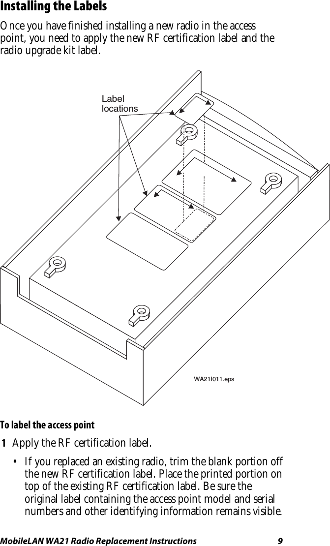
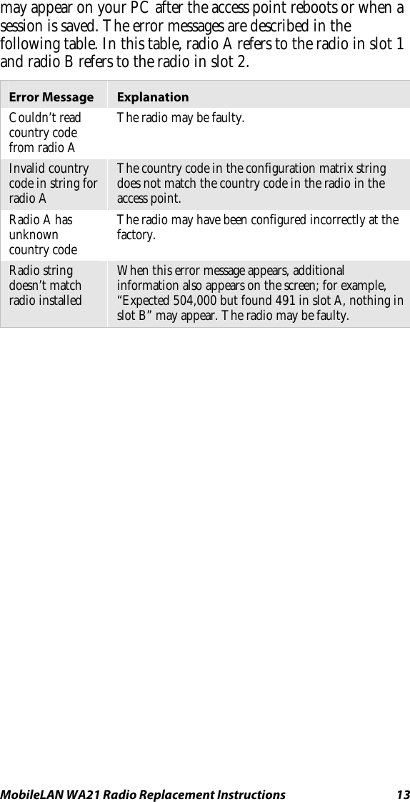
User Manual 1
Contents
1.
User Manual 1
2.
User Manual 2
3.
User Manual 3
User Manual 1
Navigation menu
Upload a User Manual
Namespaces
Wiki Guide
HTML
PDF
Info
Views
User Manual
Discussion / Help
Navigation