Intex Development SM24101-T Transmitter for Swim Trainer User Manual
Intex Development Company Limited Transmitter for Swim Trainer Users Manual
Users Manual
303
PO
(303PO) MODEL SM24101 SWIMMING MACHINE ENGLISH 7.5” X 10.3” PANTONE 295U 02/21/2017
English
OWNER’S MANUAL
IMPORTANT
SAFETY RULES
Read, understand, and follow
all instructions carefully before
installing and using this product.
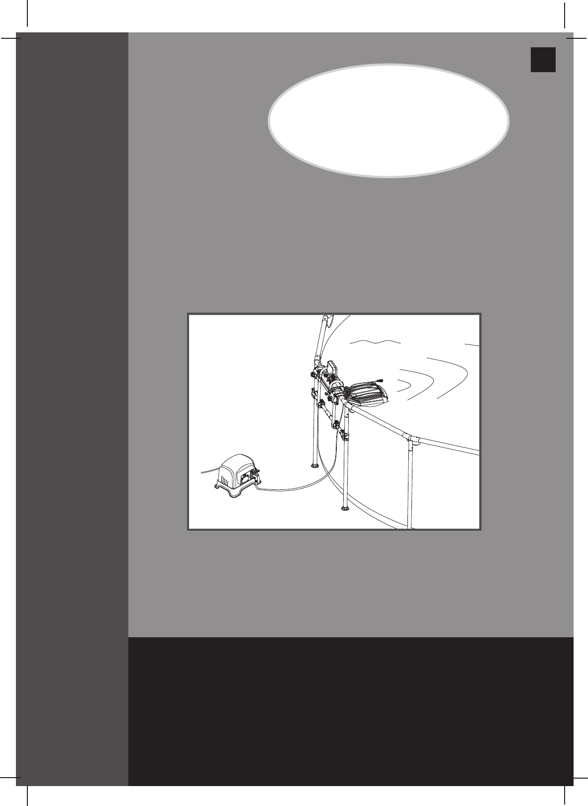
For illustrative purposes only. Pool not included.
Hydro Flow™ Swim Trainer
Model SM24101
110-120V AC / 60Hz
IMPORTANT!
DO NOT RETURN PRODUCT TO STORE
To purchase parts and accessories or to obtain non-technical assistance, Visit
www.intexcorp.com
For technical assistance and missing parts call us toll-free (for U.S. and Canadian Residents):
1-800-234-6839
Monday through Friday, 8:30am to 5:00pm Pacific Time303-*PO-R0-1702
Don’t forget to try these other fine Intex products: pools, pool
accessories, inflatable pools and in-home toys, airbeds and boats
available at fine retailers or visit our website.
Due to a policy of continuous product improvement, Intex reserves the
right to change specifications and appearance, which may result in
updates to the instruction manual without notice.

(303PO) MODEL SM24101 SWIMMING MACHINE ENGLISH 7.5” X 10.3” PANTONE 295U 02/21/2017
303
PO
SAVE THESE INSTRUCTIONS
English
Page 2
Warnings..................................................................................... 3
Parts Reference.......................................................................... 4-5
Product Specification................................................................ 6
Setup Instructions...................................................................... 6-13
Operating Instructions............................................................... 14-15
Maintenance............................................................................... 15
Internal Parts Replacements..................................................... 16-17
Troubleshooting Guide.............................................................. 18-19
Limited Warranty......................................................................... 20
TABLE OF CONTENTS
Operation is subject to the following two conditions: (1) this device may not cause interference,
and (2) this device must accept any interference, including interference that may cause
undesired operation of the device.
Changes or modifications not expressly approved by the party responsible for compliance could
void the user’s authority to operate the equipment.
This equipment has been tested and found to comply with the limits for Class B digital device,
pursuant to part 15 of the FCC Rules. These limits are designed to provide reasonable protection
against harmful interference in a residential installation. This equipment generates, uses and can
radiate radio frequency energy and, if not installed and used in accordance with the instructions,
may cause harmful interference to radio communications. However, there is no guarantee that
interference will not occur in a particular installation. If this equipment does cause harmful
interference to radio or television reception, which can be determined by turning the equipment
off and on, the user is encouraged to try to correct the interference by one or more of the
following measures:
• Reorientorrelocatethereceivingantenna.
• Increasetheseparationbetweentheequipmentandthereceiver.
• Connecttheequipmentintoanoutletonacircuitdifferentfromthattowhichthe
receiver is connected.
• Consultthedealeroranexperiencedradio/TVtechnicianforhelp.
(303PO) MODEL SM24101 SWIMMING MACHINE ENGLISH 7.5” X 10.3” PANTONE 295U 02/21/2017
303
PO
SAVE THESE INSTRUCTIONS
English
Page 3
IMPORTANT SAFETY RULES
Read, Understand and Follow All Instructions Carefully Before Installing and Using this Product.
READ AND FOLLOW ALL INSTRUCTIONS
WARNING
• Toreducetheriskofinjury,donotpermitchildrentousethisproduct.Alwayssupervisechildrenandthosewith
disabilities.
• Childrenmuststayawayfromthisproductandelectricalcord(s).
• Assemblyanddisassemblybyadultsonly.
• Cleaningandusermaintenancemustbeperformedbyadultsonlywhounderstandtheriskofelectricshock.
• Fordomesticpooluseonly.Not for commercial use.
• Riskofelectricshock.Ifreplacement of the plug or cord is needed, use only identical replacement parts.
• Alwaysunplugthisproductfromtheelectricaloutletbeforeremoving,cleaning,servicingormakinganyadjustment
to the product.
• Riskofelectricshock.Connectthisproductonlytoagroundingtypereceptacleprotectedbyaground-faultcircuit
interrupter (GFCI) or residual current device (RCD). Contact a qualified electrician if you cannot verify that the
receptacleisprotectedbyaGFCI/RCD.UseaqualifiedelectriciantoinstalltheGFCI/RCD,whichhasamaximum
rate of 30mA. Do not use a portable residual current device (PRCD).
• Donotburytheelectricalcord.Locatethecordwhereitwillnotbedamagedbylawnmowers,hedgetrimmersand
other equipment.
•
Toreducetheriskofelectricshock,replacedamagedcordimmediately.Useaqualifiedelectriciantoreplacethecord.
• Toreducetheriskofelectricshock,donotuseextensioncords,timers,plugadaptorsorconverterplugsto
connect unit to electric supply; provide a properly located outlet.
• Theapplianceisonlytobeusedwiththeprovidedtransformer.
• Donotattempttopluginorunplugthisproductwhilestandinginwaterorwhenyourhandsarewet.
•
Donotuseanapplianceleakagecurrentinterrupter(ALCI)inplaceofaGFCIsincetheALCIwillnotprotectpeople.
• Positionthetransformerawayfromthepool,soastopreventchildrenfromclimbingonitandaccessingthepool.
• Pool covers must be completely removed before using this product.
• Peopleusingmedicationsand/orhavinganadversemedicalhistoryshouldconsultaphysicianbefore
using this product.
• Donotusedrugsoralcoholbeforeorduringtheuseofthisproduct.
• Do not use this product when it is snowing, raining, thundering or lightning.
• Donotusethisproductimmediatelyfollowingstrenuousexercise.
• Donotsit,straddle,steporexertpressureontheproductasinjurycouldoccur.
• Neverplayorswimneartheswimtrainerventholes.
• Keephairawayfromtheswimtrainerventholes.Yourhairmaybetrappedcausingpermanentinjuryordrowning.
Wear a swim cap.
• Donotobstructtheswimtrainerventholes.
• Thisproductisintendedtobeusedonlyforthepurposesdescribedinthemanual!
FAILURE TO FOLLOW THESE WARNINGS MAY RESULT IN PROPERTY DAMAGE, ELECTRIC SHOCK,
ENTANGLEMENT OR OTHER SERIOUS INJURY OR DEATH.
(303PO) MODEL SM24101 SWIMMING MACHINE ENGLISH 7.5” X 10.3” PANTONE 295U 02/21/2017
303
PO
SAVE THESE INSTRUCTIONS
English
Page 4
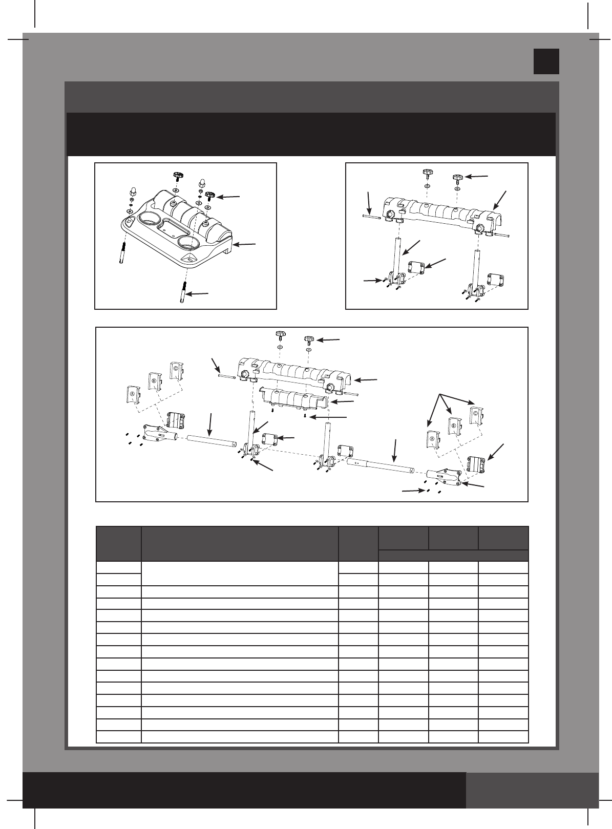
Intex Rectangular Frame Pool Mounting Bracket
In Ground Pool Mounting Bracket
PARTS REFERENCE
Beforeassemblingyourproduct,pleasetakeafewminutestocheckthecontents
and become familiar with all the parts.
5
4
1
4
7
8
6
92
4
3
15
9
8
8
6
710
12
11
14
13
2
Intex Round Frame Pool Mounting Bracket.
NOTE: Drawings for illustration purpose only. Actual product may vary. Not to scale.
REF. NO.
DESCRIPTION QTY.
IGP
POOL
Intex Rectangular
Frame Pool
Intex Round Frame
Pool
SPARE PART NO.
1MountingBracket 1 12591 - -
21-12592 12592
3 Bracketspacefiller 1-12593 12593
4Mountingbracketscrew 212396 12396 12396
5 Anchor screws 2 12407 - -
6Bracketpole 2-12594 12594
7 Bracketpolefixer 2-12595 12595
8 Screws 16 -12598 12598
9 Pin 2-12406 12406
10 Horizontal pipe lugs 2- - 12597
11 A/B/Cgapfillerset 2- - 12405
12 Horizontal pipe fixer 2- - 12596
13 Horizontal pipe A 1- - 12403
14 Horizontal pipe B 1- - 12402
15 screws 2-12599 12599
(303PO) MODEL SM24101 SWIMMING MACHINE ENGLISH 7.5” X 10.3” PANTONE 295U 02/21/2017
303
PO
SAVE THESE INSTRUCTIONS
English
Page 5
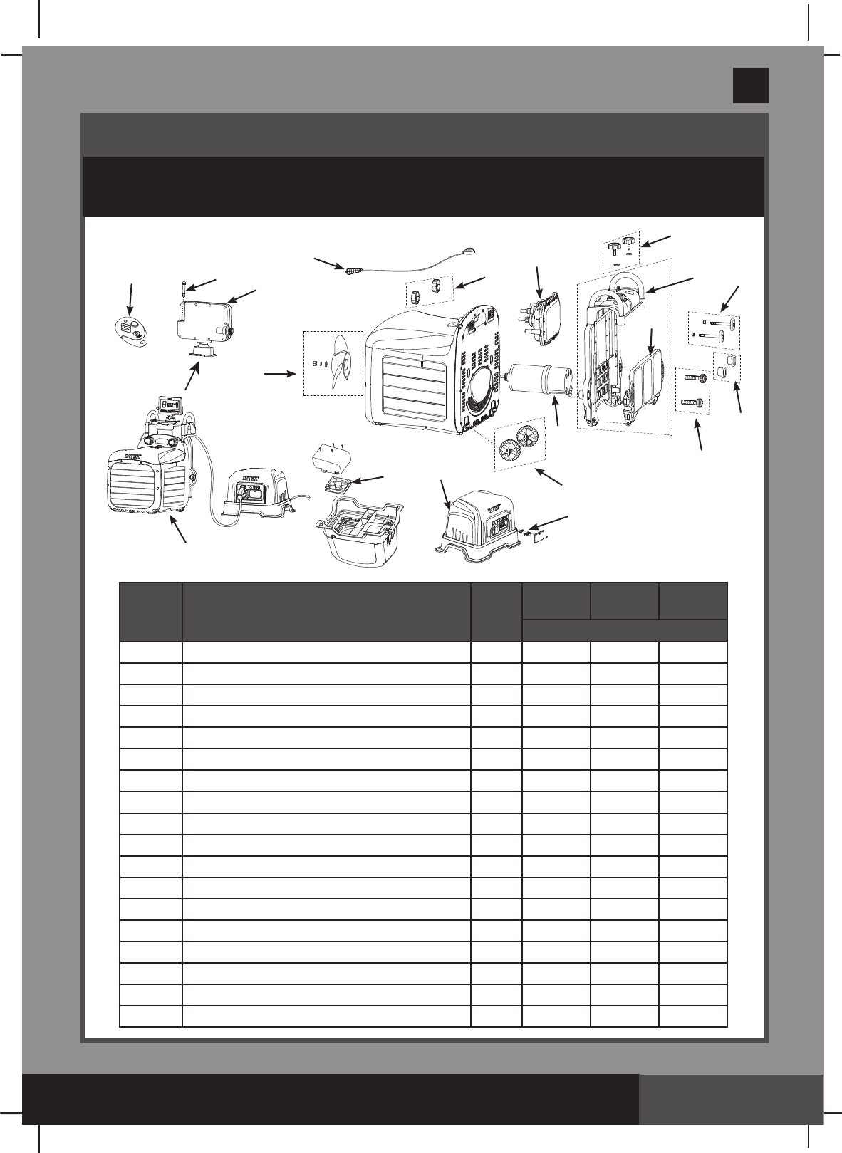
PARTS REFERENCE (continued)
Beforeassemblingyourproduct,pleasetakeafewminutestocheckthecontents
and become familiar with all the parts.
REF. NO.
DESCRIPTION QTY.
IGP
POOL
Intex Rectangular
Frame Pool
Intex Round Frame
Pool
SPARE PART NO.
16 Display panel 112379 12379 12379
17 Display panel antenna 112391 12391 12391
18 Remote control 112381 12381 12381
19 Emergency stop lanyard 112374 12374 12374
20 Clampknob 212395 12395 12395
21 Circuitry box 112387 12387 12387
22 Supportbracket 112398 12398 12398
23 Support plate 112399 12399 12399
24 Adjustable bolt with nut 212397 12397 12397
25 Anchor adjustable bolt 212390 -12390
26 Wheels 212389 12389 12389
27 Motor 112383 12383 12383
28 Transformer 112377 12377 12377
29 Transformer fuse 112394 12394 12394
30 Transformer fan 112393 12393 12393
31 Propellerkit 112385 12385 12385
32 Swim-trainer unit 112375 12375 12375
33 Adjustable bolt spacer 2 12600 12600 12600
16
18
19
20
31
21
22
23
24
25
33
26
29
28
30
27
4
17
32
(303PO) MODEL SM24101 SWIMMING MACHINE ENGLISH 7.5” X 10.3” PANTONE 295U 02/21/2017
303
PO
SAVE THESE INSTRUCTIONS
English
Page 6
• Poolmustbelledwithwaterpriortoinstallation.Twoadultsrequired.
• Tools required:onePhilipscrewdriver,oneatscrewdriverandonesmalladjustable
wrench.
• Pool size requirements:
Pool water depth: 100cm (39 inch) minimum.
Pool length: 4.6m (15') minimum.
Pool width: 2.5m (8.2') minimum.
Transformer Location Requirement
1. The transformer must be installed on a solid level and vibration-free area.
2.Providealocationprotectedfromtheweather,moisture,rain,splashingwater,ooding
and freezing temperature.
3. Provide adequate access, space and lighting for routine maintenance.
4. The transformer requires free circulation of air for cooling.
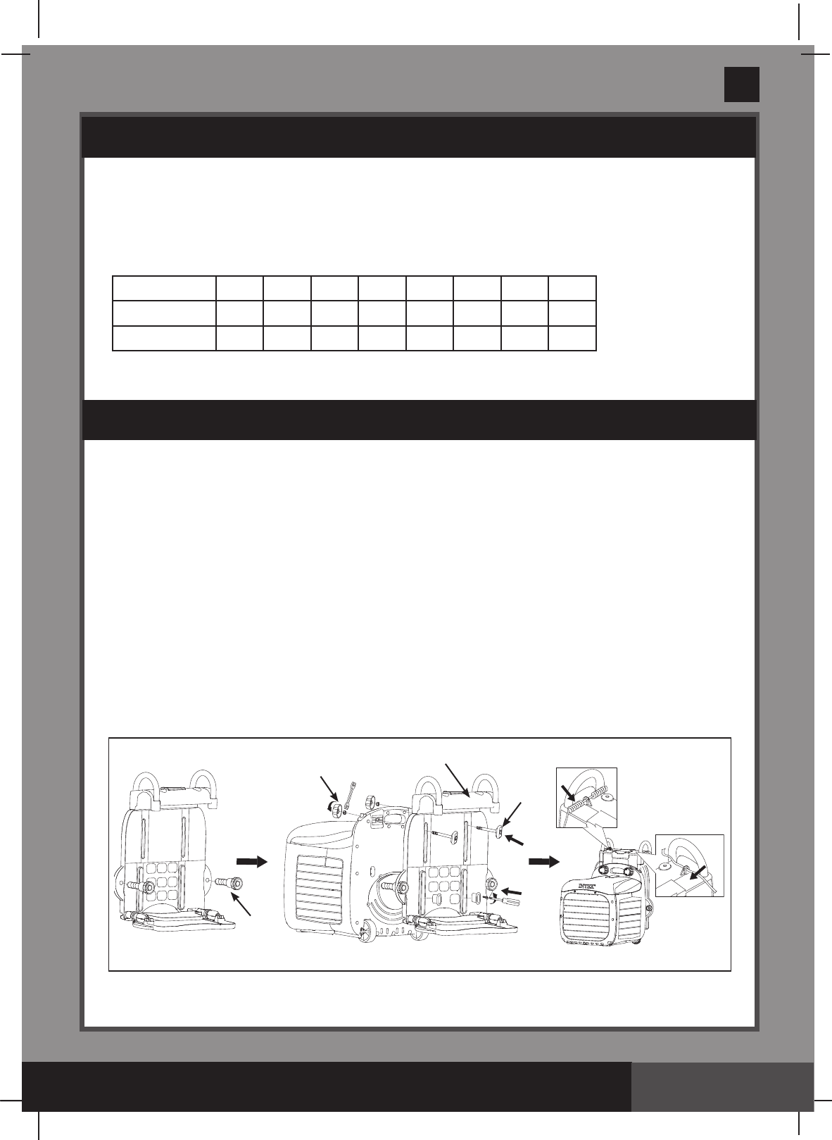
Swim-Trainer Unit and Support Bracket Assembly, for all type of pools.
NOTE: Make sure the pool wall is able to support a load of 25 kg (55 Lbs) or more
before installation.
Model: SM24101
Voltage: Transformerinput110-120VAC/60Hz8A
Transformeroutput24VDC35A
Suitable for: In ground pool or Intex above ground metal frame pools
Pool water temperature range: 25ºC - 35ºC
* Approximate
PRODUCT SPECIFICATIONS
SETUP INSTRUCTIONS
Speed Setting*
12345678
m/s 0.66 0.77 0.83 0.94 0.98 1.06 1.16 1.21
ft/s 2.17 2.53 2.72 3.08 3.22 3.48 3.81 3.97
This device generates a constant flow of pool water that allows the user to swim
uninterrupted in the swimming pool.
25
20
24
22
(303PO) MODEL SM24101 SWIMMING MACHINE ENGLISH 7.5” X 10.3” PANTONE 295U 02/21/2017
303
PO
SAVE THESE INSTRUCTIONS
English
Page 7
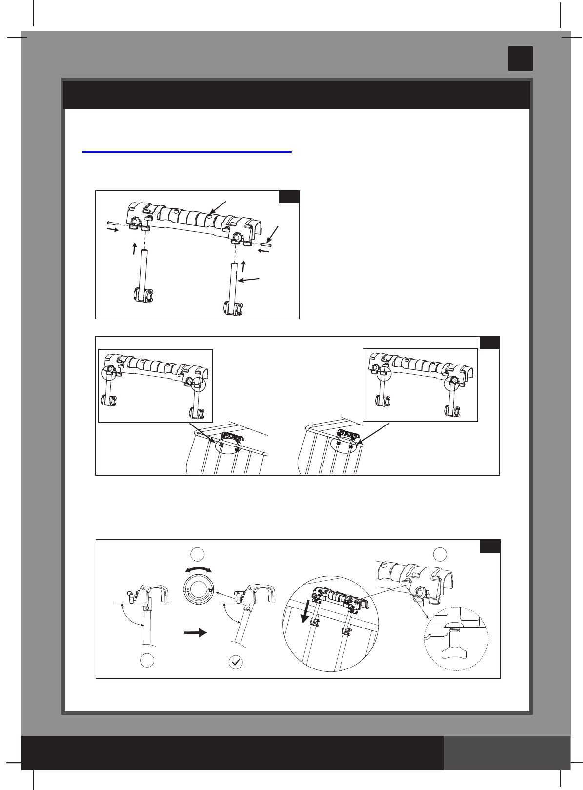
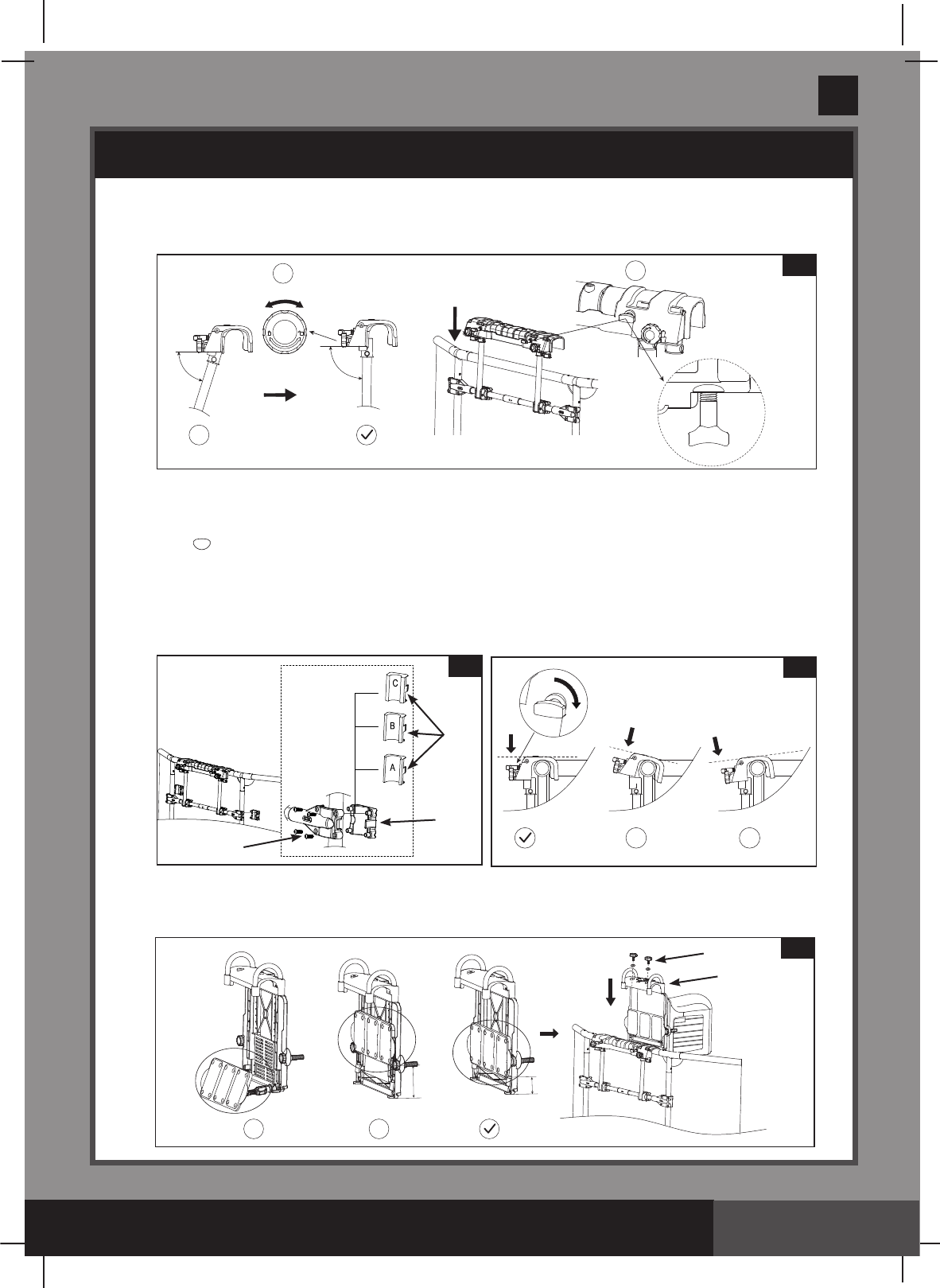
Pool Mounting Bracket Assembly
A: For Intex Rectangular Frame Pools
1.
Mounting Bracket Assembly (see gures 1.1 to 1.2):
NOTE: Center the swim-trainer unit on the short-end side of the pool.
2. Installing the mounting bracket assembly onto a rectangular frame pool wall
(see gures 2.1 to 2.3)
SETUP INSTRUCTIONS (continued)
X
1 2 2.1
2
6
9
1.1
OR
1.2
(303PO) MODEL SM24101 SWIMMING MACHINE ENGLISH 7.5” X 10.3” PANTONE 295U 02/21/2017
303
PO
SAVE THESE INSTRUCTIONS
English
Page 8
12
3.2
Water level
90 Degree
• LockthebracketpolesandmountingbracketassemblyontotheU-shapedside
supportwiththebracketpolexer(7) and screws (8). (see gure 2.2).
NOTE: Makesureallthescrewsaresecurelytightenedandthemountingbracket
top surface is level.
3. Swim-Trainer Unit Assembly (see gures 3.1 to 3.2).
• Be sure the swim-trainer unit“supportbracket”isclosedbeforeinstallingthe
swim-trainer unitontothemountingbracketassembly (see figure 3.1).
• Extend the support plate, and adjust the depth by loosening the arm collar and
extending the support plate arm until the swim-trainer unit is perfectly horizontal,
retightentolockitinplace.NOTE: The support plate must rest against the inside of
the pool wall surface. (see gure 3.2).
SETUP INSTRUCTIONS (continued)
X X
2.32.2
7
8
XX
3.1
4
22
MIN
(303PO) MODEL SM24101 SWIMMING MACHINE ENGLISH 7.5” X 10.3” PANTONE 295U 02/21/2017
303
PO
SAVE THESE INSTRUCTIONS
English
Page 9
B: For Intex Round Frame Pools
1. Mounting Bracket Assembly (see figures 4.1 to 4.5):
• Identify the frame pool pipe shape. For “ ”shapepipeseegure4.2to4.5.
For“O”shapepipeseegure4.3to4.5.
• For “ ”shapepipe,removethebracketspaceller(3)fromthemountingbracket(2).
(see gure 4.2). For“O”shapepipegotonextstep.
• Insertthebracketpoles(6)intothemountingbracket(2) inner holes (see gure 4.3).
• Connect the horizontal pipe A (13) with horizontal pipe B (14) together, then attach
thehorizontalpipeassemblytothemountingbracketassemblyusingthebracket
pole xer (7) and screws (8) (see gures 4.4 to 4.5).
SETUP INSTRUCTIONS (continued)
4.1
4.3
2
6
9
4.2
2
3
4.54.4
12
13
14
8
8
7
(303PO) MODEL SM24101 SWIMMING MACHINE ENGLISH 7.5” X 10.3” PANTONE 295U 02/21/2017
303
PO
SAVE THESE INSTRUCTIONS
English
Page 10
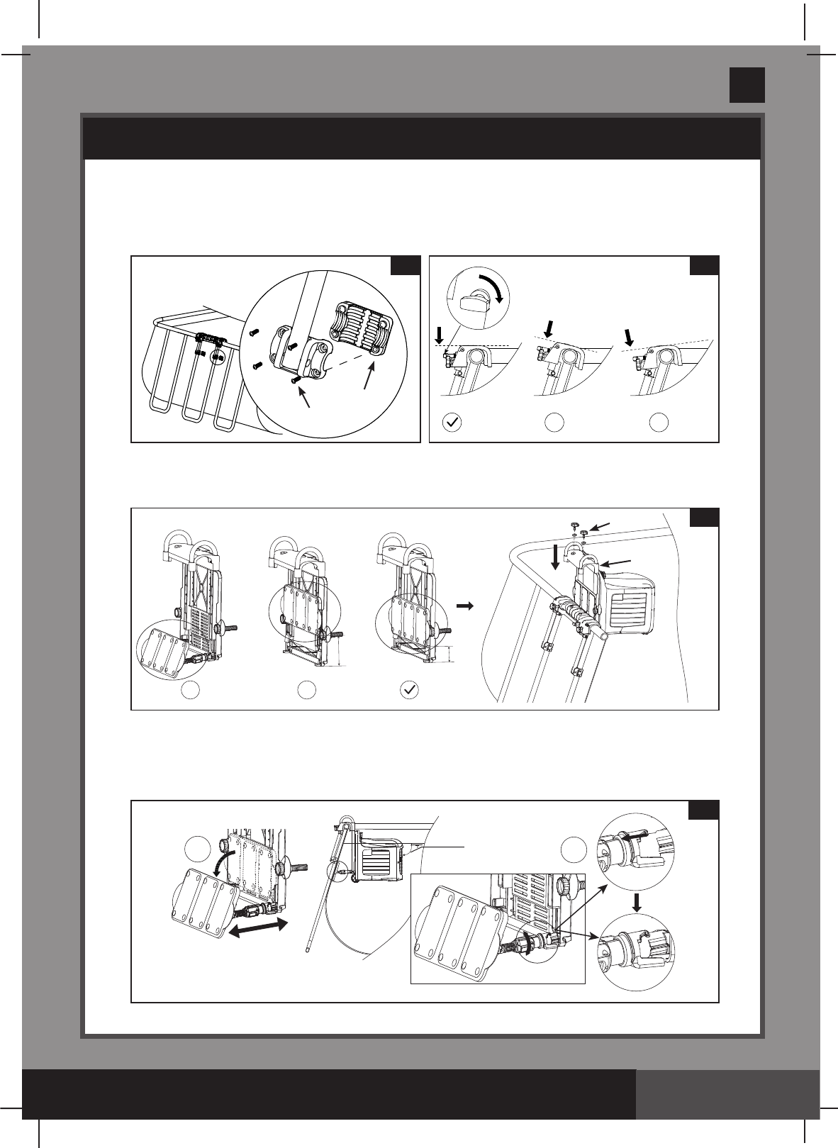
2. Installing the mounting bracket assembly onto a round frame pool wall
(see figures 5.1 to 5.3):
• Attachthemountingbracketassemblyontotheframepoolverticallegswiththe
horizontal pipe lugs (10), screws (8), and depending on the shape of the vertical leg
pipeincludeA/B/Cgapller(11) (see gure 5.2).
For “ ”shapeverticallegpipe,donotincludetheA/B/Cgapller(11).
For38mmdiameterverticallegpipeinclude“A”gapller.
For44mmdiameterverticallegpipeinclude“B”gapller.
For48mmdiameterverticallegpipeinclude“C”gapller.
NOTE: Makesureallthescrewsaresecurelytightenedandthemountingbrackettop
surface is level.
3. Swim-Trainer Unit Assembly (see gures 5.4 to 5.5).
• Be sure the swim-trainer unit“supportbracket”isclosedbeforeinstallingthe
swim-trainer unitontothemountingbracketassembly (see gure 5.4).
5.2
10
11
8
SETUP INSTRUCTIONS (continued)
X X
5.3
X
125.1
XX
5.4
4
22
MIN
(303PO) MODEL SM24101 SWIMMING MACHINE ENGLISH 7.5” X 10.3” PANTONE 295U 02/21/2017
303
PO
SAVE THESE INSTRUCTIONS
English
Page 11
6.3
5
1
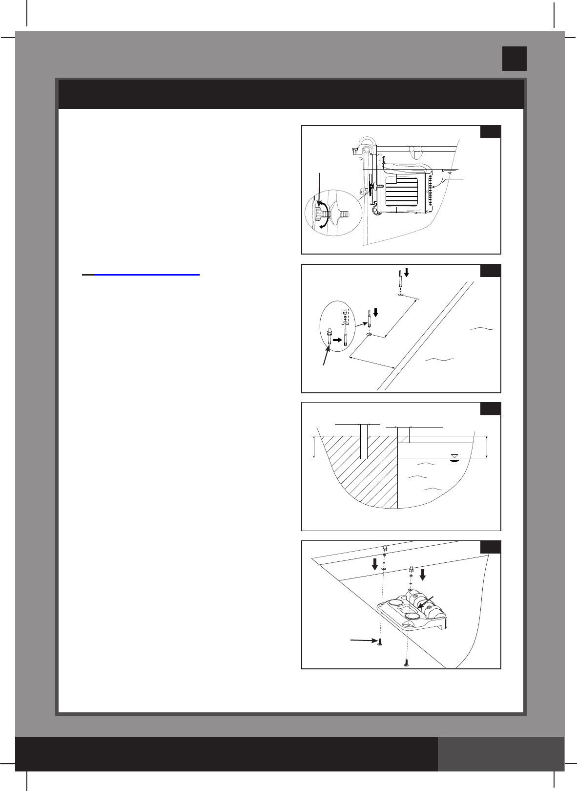
• Adjust the nut on the swimming machine
until the support plate is against the pool
wall and the swim-trainer unit is perfectly
horizontal (see figure 5.5).
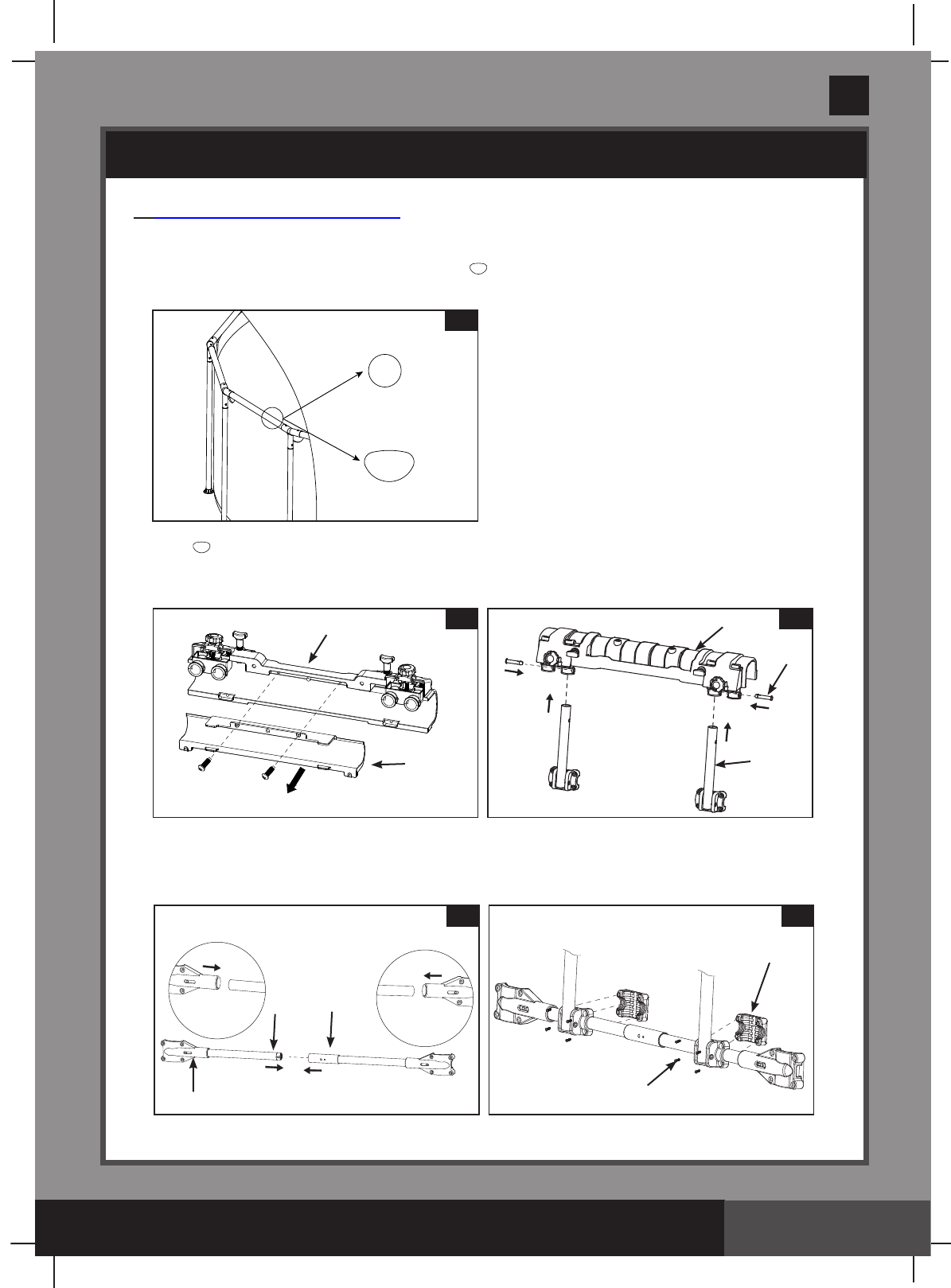
C: For In Ground Pools
1. Mounting Bracket Assembly (see
figures 6.1 to 6.3):
• Makesurethetopsurfaceofthepool
edge is stable, flat and level.
• Payattentiontotheelectrical,gasand
water lines when drilling the holes.
• All screws provided must be used.
• Drill two holes on the center of the
short-end side of the pool edge where the
mountingbracketwillbeinstalled.Insert
the in ground pool screws (5) into the
holes,andmakesurethescrewsare
fully inserted (see figures 6.1 to 6.2).
• Place the in ground pool mounting
bracket(1) over the installed screws (5)
and tighten the nuts securely
(see figure 6.3).
SETUP INSTRUCTIONS (continued)
5.5
Water level
90
Degree
Ajustable nut
for adjusting the
distance
215mm(8.5”)
332mm(13”)
6.1
5
100~250mm(4~10”)
50mm(2”)
Ø10mm(0.4”)
MAX 40mm(1.5”)
6.2
Water level
(303PO) MODEL SM24101 SWIMMING MACHINE ENGLISH 7.5” X 10.3” PANTONE 295U 02/21/2017
303
PO
SAVE THESE INSTRUCTIONS
English
Page 12
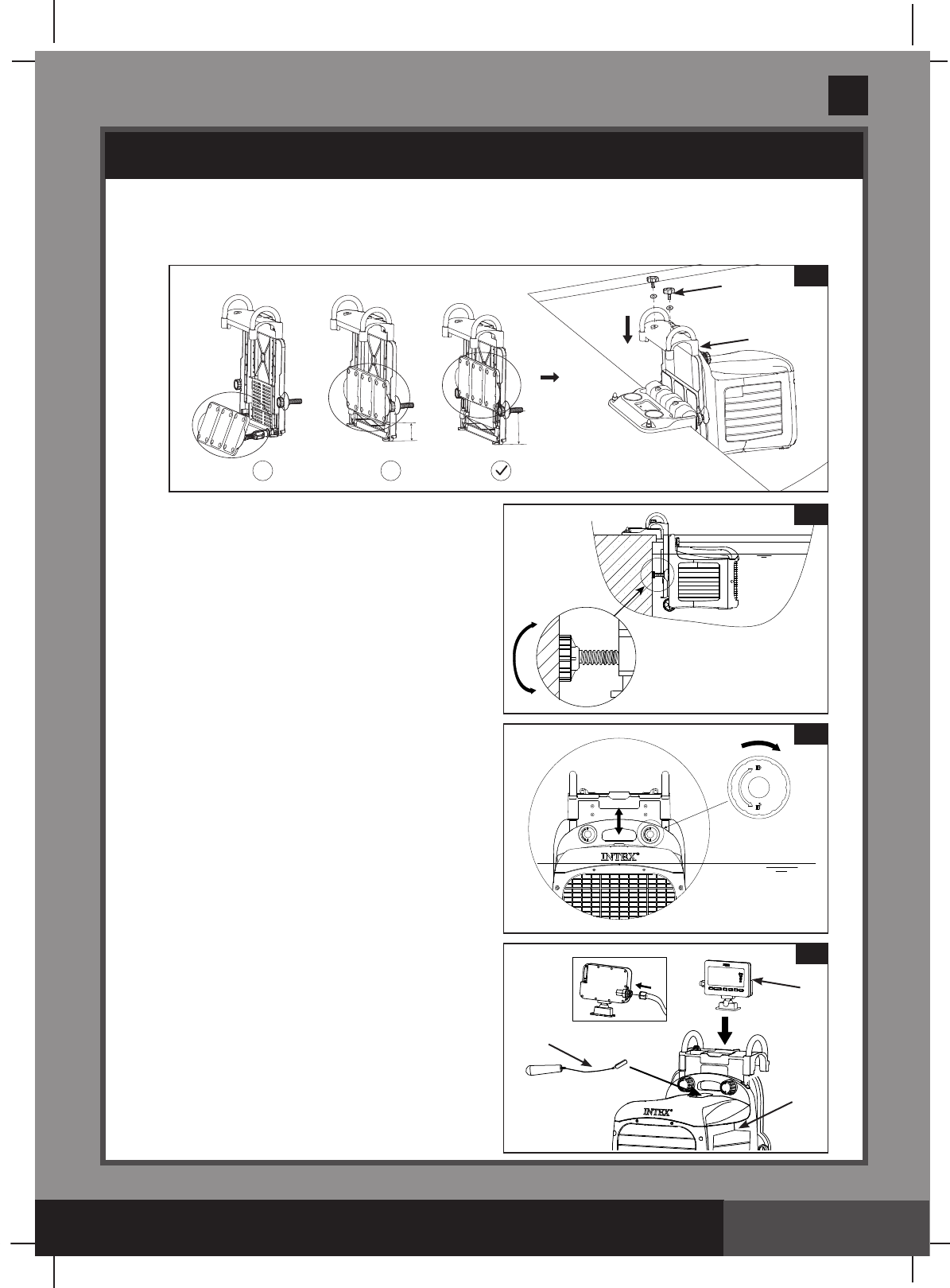
2. Swim-Trainer Unit Assembly (see gures 6.4 to 6.5).
• Be sure the swim-trainer unit“supportbracket”isclosedbeforeinstallingthe
swim-trainer unitontothemountingbracketassembly (see gure 6.4).
• Adjust the support nuts on the
swim-trainer unit until the swim-trainer
unit is horizontal with the water surface
(see figure 6.5).
Swim-Trainer Unit height adjustment
and display panel assembly, for all
types of pools
1. The swim-trainer unit must be submerged
in water with only the top surface of the
housingexposed.Lockthenutsinplace
after the height of the swim-trainer unit
is adjusted (see figure 7).
2. Attach the display panel (16) onto the
swim-trainer unitmountingbracket.
Connect the display cable plug to the
display panel receptacle. Tighten up the
display cable collar nut (see figure 8) by
hand.Makesurethedisplaycableplugis
firmly attached and the collar nut is
securely tightened.
3. Place the flat magnetic end of the
emergency stop lanyard (19) on the
swim-trainer unit (32) housing in order
to activate the unit (see figure 8).
IMPORTANT: During an emergency
situation, pull the emergency stop
lanyard handle, the unit will stop and
thedisplaypanelwillgoblank.
8
16
32
19
SETUP INSTRUCTIONS (continued)
6.5
Water level
7
Water level
X X
6.4
4
22
Max
(303PO) MODEL SM24101 SWIMMING MACHINE ENGLISH 7.5” X 10.3” PANTONE 295U 02/21/2017
303
PO
SAVE THESE INSTRUCTIONS
English
Page 13
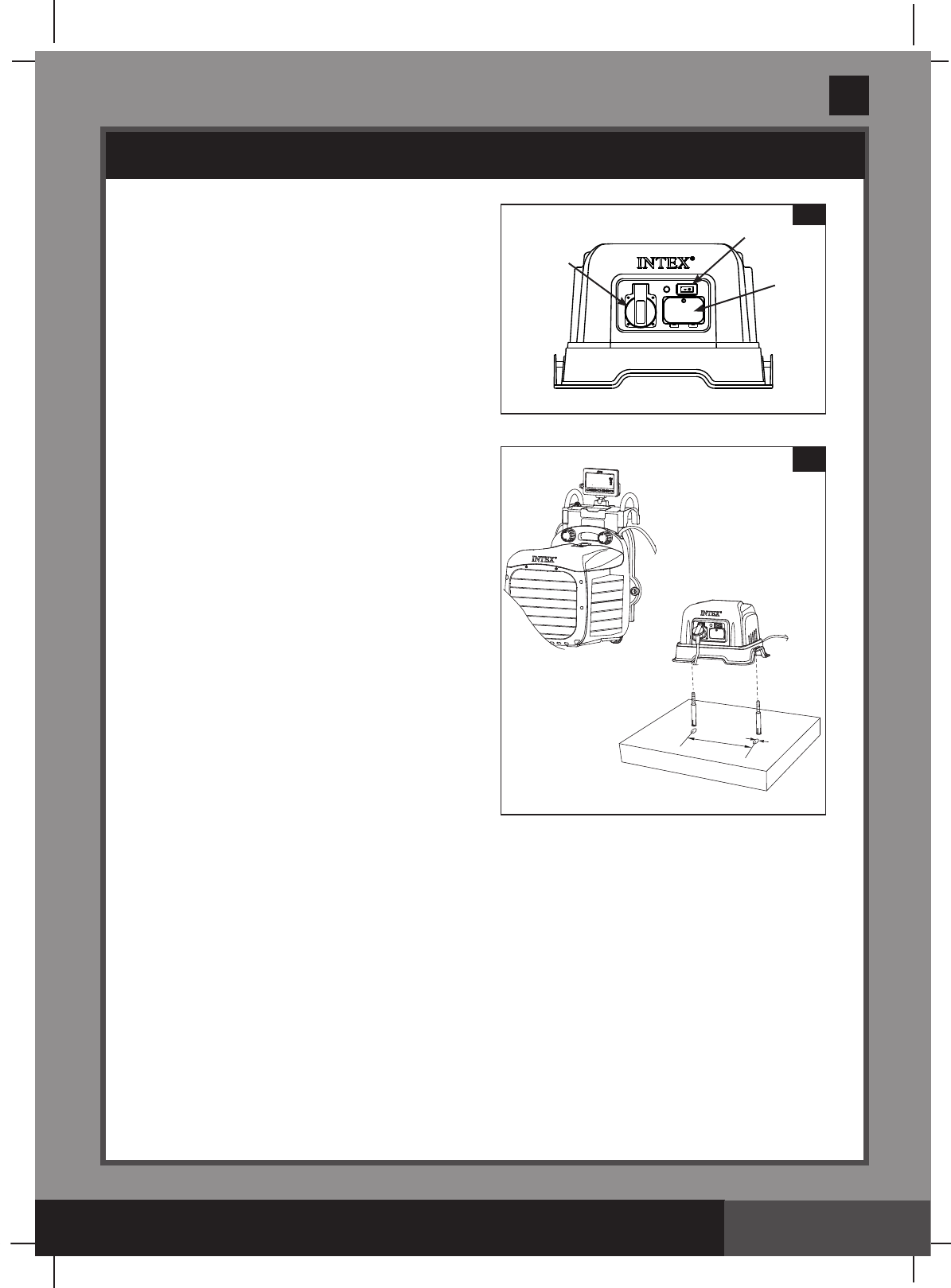
Connecting the swim-trainer unit to the
transformer (see gures 9.1 to 9.2).
1. Be sure the transformer (2) switch is
OFF, connect the transformer cable to
a grounded electrical outlet.
2. Transformermustbexedtoasolid,
level ground or base. Connect the
swim-trainer unit power cable plug into
the transformer power receptacle. Be
sure the plug collar is securely tightened
(see gure 9.1 to 9.2).
3. Position the transformer 2m or more away
from the pool, so as to prevent children
from climbing on it and accessing the pool.
4. Test the GFCI or RCD before use:
a) Pressthe“RESET”button.The
indicatorontheRCDshouldbe“ON”.
b) Pressthe“TEST”button.Theindicator
ontheRCDshouldbe“OFF”.
c) Pressthe“RESET”buttonagainto
start using the product.
d) Do not use the product if the test
failed.Contactaqualiedelectricianto
inspecttheelectricaloutletsocket.
5. Turn the transformer switch ON.
NOTE: To reactivate the swim-trainer unit after the emergency stop lanyard is pulled,
replacetheemergencystoplanyardbackintotheswim-trainer unit, unplugged and
re-plugged the power cable from the transformer.
SETUP INSTRUCTIONS (continued)
425mm
6.4mm
9.2
9.1
ON/OFFSwitch
Fuse Box
Power
receptacle
(303PO) MODEL SM24101 SWIMMING MACHINE ENGLISH 7.5” X 10.3” PANTONE 295U 02/21/2017
303
PO
SAVE THESE INSTRUCTIONS
English
Page 14
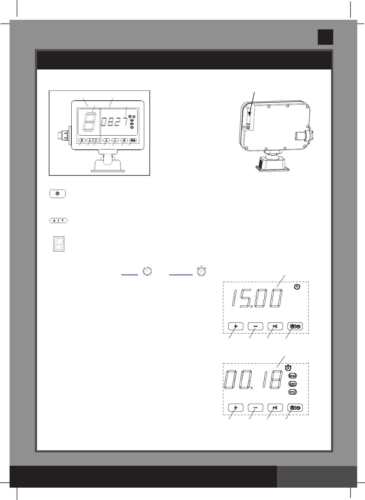
Display Panel Function
Zone #1 Function
A:On/OffButton
B: Speed Increase Button
C: Speed Decrease Button
D: Speed Setting Display
OPERATION INSTRUCTIONS
Antenna
Zone #1 Function Zone #2 Function
A B C
DI
E F G H
A: On/Off Button: Once the swim-trainer unit is connected to the
transformer and the transformer turned ON, use this button to active the system.
TheLEDpanelwillshowthedefaultspeedsettingonceactivated.
B/C: Speed Adjustment Buttons: Press to increase or decrease the speed setting.
NOTE: The default speed is 3; speed adjustment ranges from 1 to 8.
D: Speed Setting Display: Once activated the system displays the swim-trainer
unit speed automatically.
Zone #2 Function
H: Toggle button between Timer “”and Counter “”Mode.
Timer Mode: Allows the user to program the duration of the
swimming time (in minutes). Once the time is reached,
the machine will stop. Maximum setting is 90 minutes.
E: Timer Increase Button
F: Timer Decrease
G:TimerReview/ConrmButton
I: TimerLEDDisplay
Counter Mode:Trackstheduration(inminutes)orcalorie
(inkcal)ordistance(inkilometerormile)oftheswim.
E/F:Counterunittogglebutton(minute/kcal
/kilometer/mile)
G: CounterOn/PauseButton.Pressfor2sec
to reset the counter.
I: CounterLEDDisplay
E F G
I
H
E F G
I
H
(303PO) MODEL SM24101 SWIMMING MACHINE ENGLISH 7.5” X 10.3” PANTONE 295U 02/21/2017
303
PO
SAVE THESE INSTRUCTIONS
English
Page 15
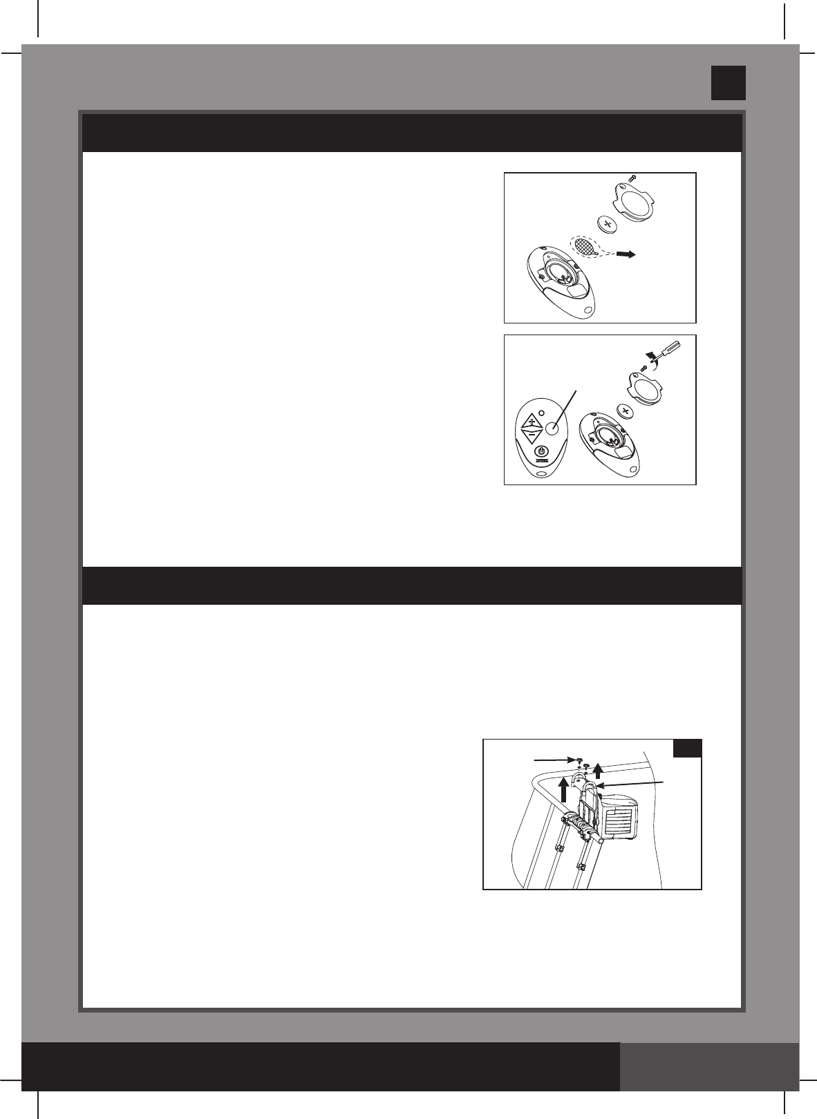
Remote Control:
1. Remove the insulation material under the battery.
Battery type (included): CR2032. Be sure the battery cover
is securely attached.
2. Place the remote control in a reachable location (on top
ofthehorizontalpoolframe).Thebackoftheremote
controlismagnetized”.
Note:Inanemergencysituation,simplypressthe“emergencycutoff”buttontoshutoffthe
system completely, the indicator light inside the remote control housing will light up and the
displaypanelwillindicate“C”.
• Checkandmakesureallscrewsaresecurelytightenedonaregularbasis.
• Whennotinuse,foldthedisplaypaneldownandcoverthepoolwithapoolcover.
Long Term Storage and Winterization
Youmustdisassembleandstoretheproductindoorswhenthetemperaturedropsbelow0OC/
32OF or when the appliance will not be used for a long period of time.
IMPORTANT: Closethesupportbracketbefore
disassembling and removing the swim-trainer unit from
themountingbracketassembly(OnlyforIntex
Rectangular Frame Pools).
1. Turn off the transformer and unplug the power cable
from the electrical outlet.
2. Disconnect the swim-trainer unit power cable from the
transformer.
3. Remove the swim-trainer unit and the
mountingbracketassemblyfromthepoolbyreversing
the installation instructions.
4. Clean the swim-trainer unit with a garden hose, and air-dry thoroughly under the sun.
5. Store the unit and accessories in a dry place. The storage’s temperature should be between
0OC/32OF and 40OC (104OF).Theoriginalpackingcanbeusedforstorage.
OPERATION INSTRUCTIONS (continued)
Emergency Cut off Button
MAINTENANCE
4
22
10
(303PO) MODEL SM24101 SWIMMING MACHINE ENGLISH 7.5” X 10.3” PANTONE 295U 02/21/2017
303
PO
SAVE THESE INSTRUCTIONS
English
Page 16
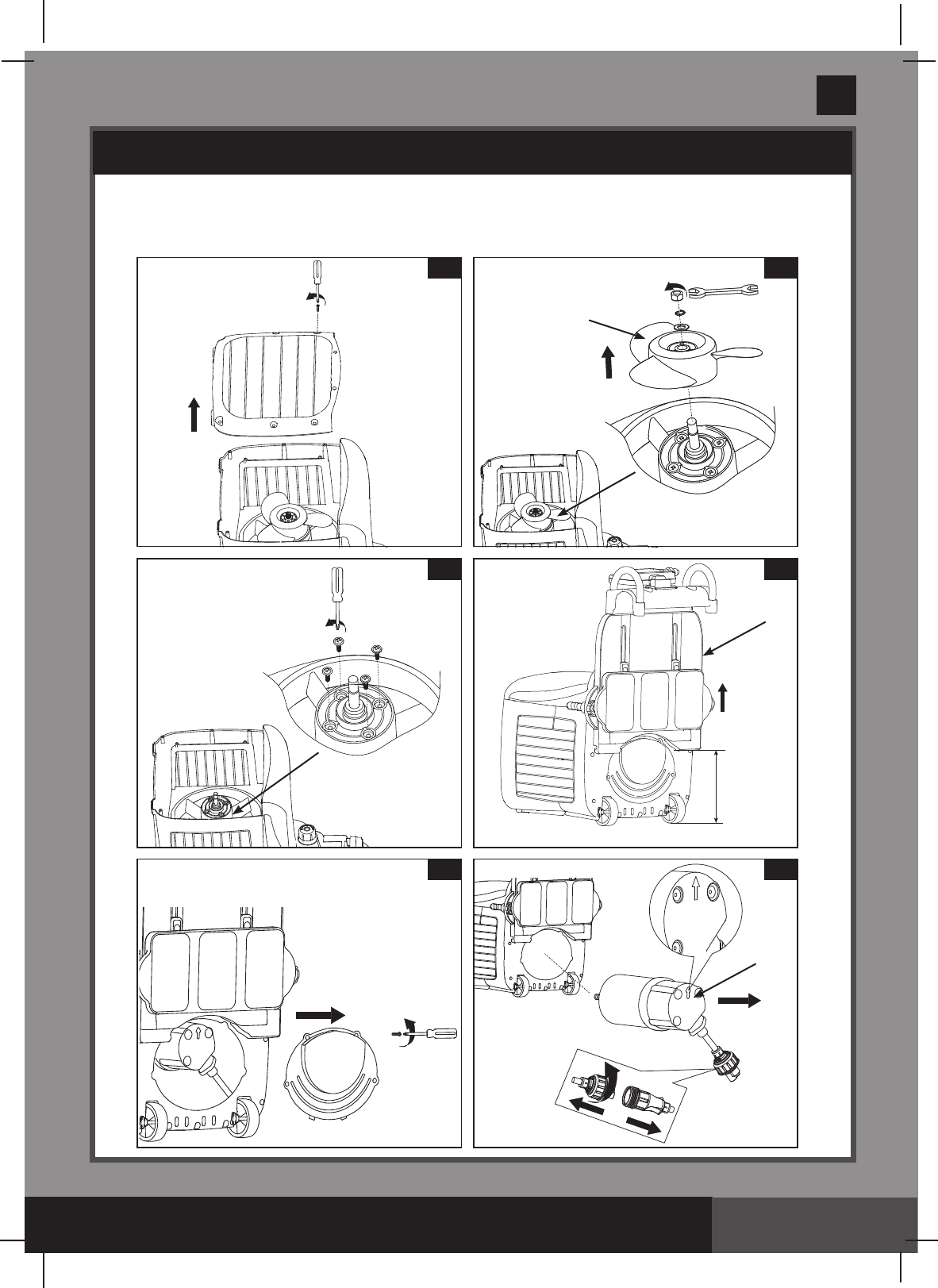
INTERNAL PARTS REPLACEMENTS
Tools required: one Philip screwdriver, one flat screwdriver and one small adjustable
wrench.
A: Propeller and motor disassembly
1
3
2
31
5 6
27
MAX
4
22
(303PO) MODEL SM24101 SWIMMING MACHINE ENGLISH 7.5” X 10.3” PANTONE 295U 02/21/2017
303
PO
SAVE THESE INSTRUCTIONS
English
Page 17
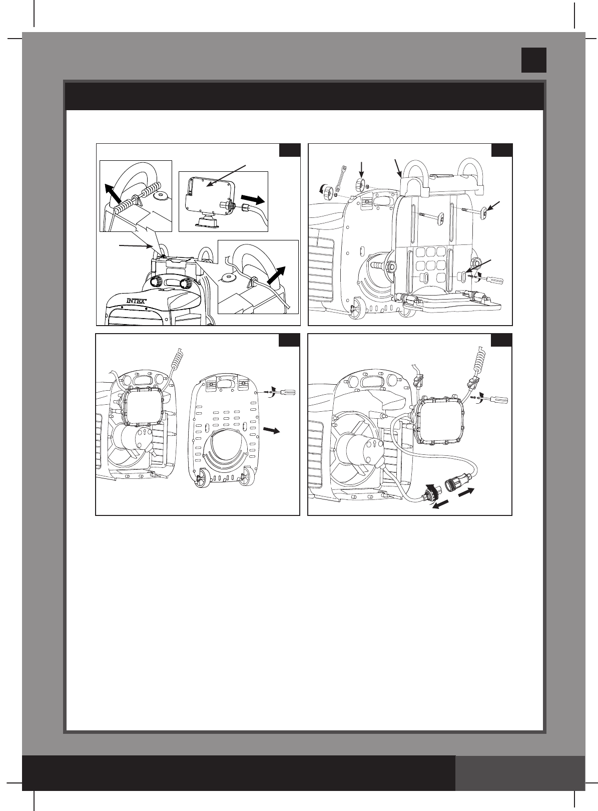
INTERNAL PARTS REPLACEMENTS (continued)
B: Swim-trainer unitbracketandcircuitryboxdisassembly
22
7
16
8
20
24
33
22
9 10

(303PO) MODEL SM24101 SWIMMING MACHINE ENGLISH 7.5” X 10.3” PANTONE 295U 02/21/2017
303
PO
SAVE THESE INSTRUCTIONS
English
Page 18
TROUBLESHOOTING GUIDE
LED PANEL
CODE PROBLEM SOLUTION
E
●The maximum operating time
(90minutes)hasnishedunderthe
same set mode.
● It's normal. Turn off and unplug the unit.
ThenplugtheRCD/GFCIbackand
restartallbackagain.
C
● Lowwaterlevel.
● swim-trainer unit is not fully immersed
in the water.
● Remote control is in an emergency cut
off situation.
● Household voltage is too low.
● Fill the pool with water up to correct water
level (see pool owner‘s manual).
● Makesurethedeviceisunderthewater.
● It‘s normal. Turn off the transformer for 1
minute, then plug in.
● Checkthevoltageiswithintherange
stated on the device housing.
H
● Household voltage is too heigh.
● Clogged motor impeller
●Checkthevoltageiswithintherange
stated on the device housing
● Turnoffthepower,checkandcleanthe
motor impeller
L
● Water temperature is around
35°C (95°F)
●
Turn off and unplug the unit. When the
waterhascooleddown,plugtheRCD/
GFCIbackandrestartalloveragain.
P
● Operating time is too long
● Water temperature is around
35°C (95°F)
●
Turn off and unplug the unit, after 30
minuteslaterplugtheRCD/GFCIback
and restart all over again.
●
Turn off and unplug the unit. When the
waterhascooleddown,plugtheRCD/
GFCIbackandrestartalloveragain.
(303PO) MODEL SM24101 SWIMMING MACHINE ENGLISH 7.5” X 10.3” PANTONE 295U 02/21/2017
303
PO
SAVE THESE INSTRUCTIONS
English
Page 19
TROUBLESHOOTING GUIDE (continued)
PROBLEM CAUSE SOLUTION
Mountingbracket
can‘t be assembled
with the in ground
pool
●The ground is not concrete, i.e., it is
asphalt, lawn or earth.
●
The screws are not fully inserted in the
drill holes.
●Assemblythemountingbracket
on the cement ground.
● Checkandtightenthescrews
securely.
swim-trainer unit is
not horizontal with
the water surface
● Thesupportbracketisnotopened.
● Adjust the support nuts on the
swim-trainer unit.
● Open and adjust the support
bracket.See“SetupInstructions”.
● Adjust the support nuts on the
swim-trainer unit.
No output from the
transformer
● swim-trainer unit will hibernate if no
operating more than 1 hour.
●Thetransformerfusebroken.
● Motor too hot and overload protection is
shut off.
● Turn off the transformer, waiting 2
minutes then turn on agin.
● Replace the transformer fuse.
●Letthemotorcooldownand
restart again.
NoLEDdisplay ● The transformer is unplugged or off.
● The transformer is not connected with
swim-trainer unit.
● Display panel cord is loose.
● Display panel failure.
● Emergency stop lanyard is put wrong
place.
● Ensure the transformer is plugged
and switched on.
● Connect the transformer with
swim-trainer unit.
● Ensure that the display cord is
pluggedrmlyintothecellhousing
receptacle.
● Contact Intex Service Center.
● Put the emergency stop lanyard
on correct place. See “Setup
Instructions”.
Abnormaldisplay/
buttonsnotworking
● Display panel cord is loose.
● Display panel failure.
●
Ensure the display cable is
pluggedrmlyintothedisplay
panel receptacle
.
●
Contact Intex Service Center.
Toonoisy/Jetwater
isweakorshaking
● Swim-trainer unit is not fully immersed in
the water.
● The motor impeller isbroken.
● swim-trainer unit components
not securely connected or in place.
●
Makesurethedeviceisunder
the water.
● Turn off and replace the motor
impeller.
●Checkallcomponents,especially
thesupportbracket.See “Setup
Instructions”.
Remote Control out
of control
● The battery is on low power.
● Replace the remote control
battery.
See“OperatingInstallations”

(303PO) MODEL SM24101 SWIMMING MACHINE ENGLISH 7.5” X 10.3” PANTONE 295U 02/21/2017
303
PO
SAVE THESE INSTRUCTIONS
English
Page 20
PARTS LIST
LIMITED WARRANTY
YourHydro Flow™ Swim Trainer has been manufactured using the highest quality materials
andworkmanship.AllIntexproductshavebeeninspectedandfoundfreeofdefectspriorto
leavingthefactory.ThisLimitedWarrantyappliesonlytotheHydro Flow™ Swim Trainer and
accessories listed below.
TheprovisionsofthisLimitedWarrantyapplyonlytotheoriginalpurchaserandisnot
transferable.ThisLimitedWarrantyisvalidfortheperiodnotedbelowfromthedateofthe
initialretailpurchase.Keepyouroriginalsalesreceiptwiththismanual,asproofofpurchase
willberequiredandmustaccompanywarrantyclaimsortheLimitedWarrantyisinvalid.
Hydro Flow™ Swim Trainer Warranty–2Years
If a manufacturing defect is found within the periods noted above, please contact the
appropriateIntexServiceCenterlistedintheseparate“AuthorizedServiceCenters”sheet.
The Service Center will determine the validity of the claim. If the Service Center directs you
toreturntheproduct,pleasecarefullypackagetheproductandsendwithshippingand
insurance prepaid to the Service Center. Upon receipt of the returned product, the Intex
Service Center will inspect the item and determine the validity of the claim. If the provisions
of this warranty cover the item, the item will be repaired or replaced at no charge.
AnyandalldisputesregardingtheprovisionsofthisLimitedWarrantyshallbebroughtbefore
an informal dispute settlement board and unless and until the provisions of these paragraphs
are carried forth, no civil action may be instituted. The methods and procedures of this
settlement board shall be subject to the rules and regulations set forth by the Federal Trade
Commission(F.T.C.).IMPLIEDWARRANTIESARELIMITEDTOTHETERMSOFTHIS
WARRANTYANDINNOEVENTSHALLINTEX,THEIRAUTHORIZEDAGENTSOR
EMPLOYEESBELIABLETOTHEBUYERORANYOTHERPARTYFORDIRECTOR
CONSEQUENTIALDAMAGESORLIABILITIES.Somestates,orjurisdictionsdonotallow
the exclusion or limitation of incidental or consequential damages, so the above limitation or
exclusion may not apply to you.
ThisLimitedWarrantydoesnotapplyiftheproductsaresubjecttonegligence,abnormaluse
or operation, accident, improper operation, improper voltage or current contrary to operating
instructions, or to damage by circumstances beyond Intex’s control, including but not limited
to, ordinary wear and tear and damage caused by exposure to fire, flood, freezing, rain, or
otherexternalenvironmentalforces.ThisLimitedWarrantyappliesonlytothosepartsand
componentssoldbyIntex.TheLimitedWarrantydoesnotcoverunauthorizedalterations,
repairs or disassembly by anyone other than Intex Service Center personnel.
DO NOT GO BACK TO THE PLACE OF PURCHASE FOR RETURN
OR REPLACEMENT. IF YOU ARE MISSING PARTS OR NEED
ASSISTANCE, PLEASE CALL US TOLL-FREE (FOR U.S. AND
CANADIAN RESIDENTS): 1-800-234-6839 OR VISIT OUR WEBSITE:
WWW.INTEXSTORE.COM.
Proof of Purchase must accompany all returns or the warranty claim will be invalid.