Intromedic INTROMEDIC2 Capsule Endoscope & Receiver User Manual 2
Intromedic Co., Ltd. Capsule Endoscope & Receiver 2
UserManual.wiki
>
Intromedic
>
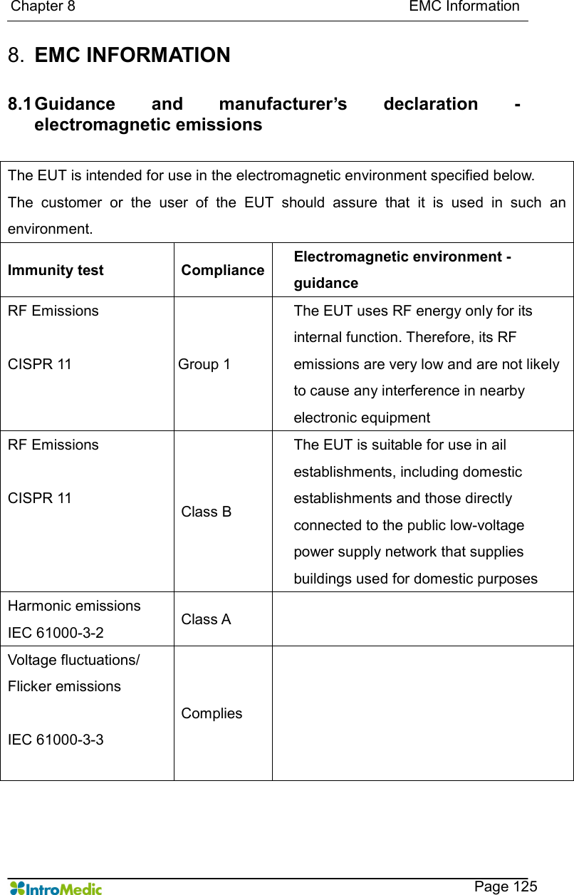
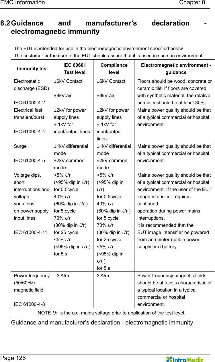
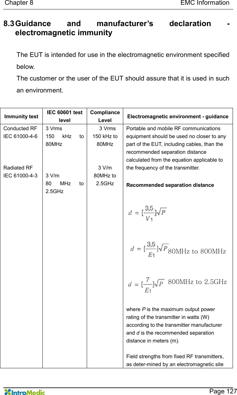
INTROMEDIC2 User Manual
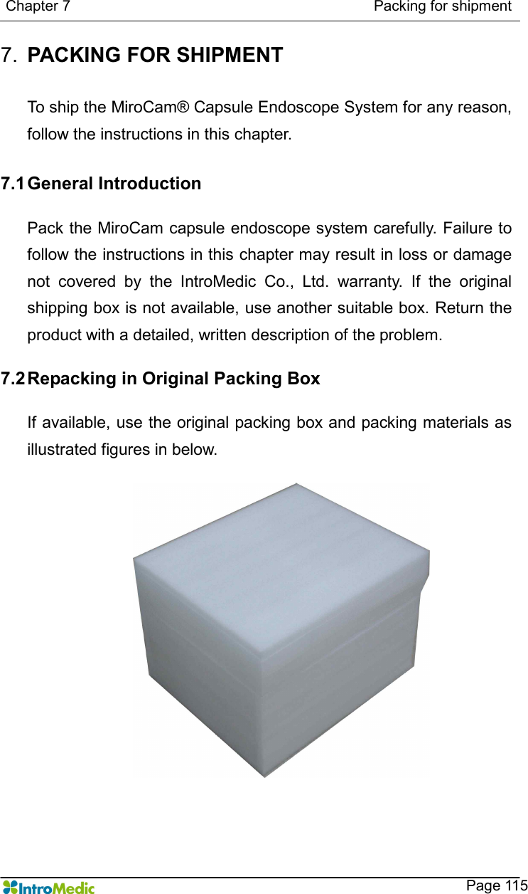
>
User Manual 2
Contents
1.
User Manual 1
2.
User Manual 2
User Manual 2
Navigation menu
Upload a User Manual
Namespaces
Wiki Guide
HTML
PDF
Info
Views
User Manual
Discussion / Help
Navigation


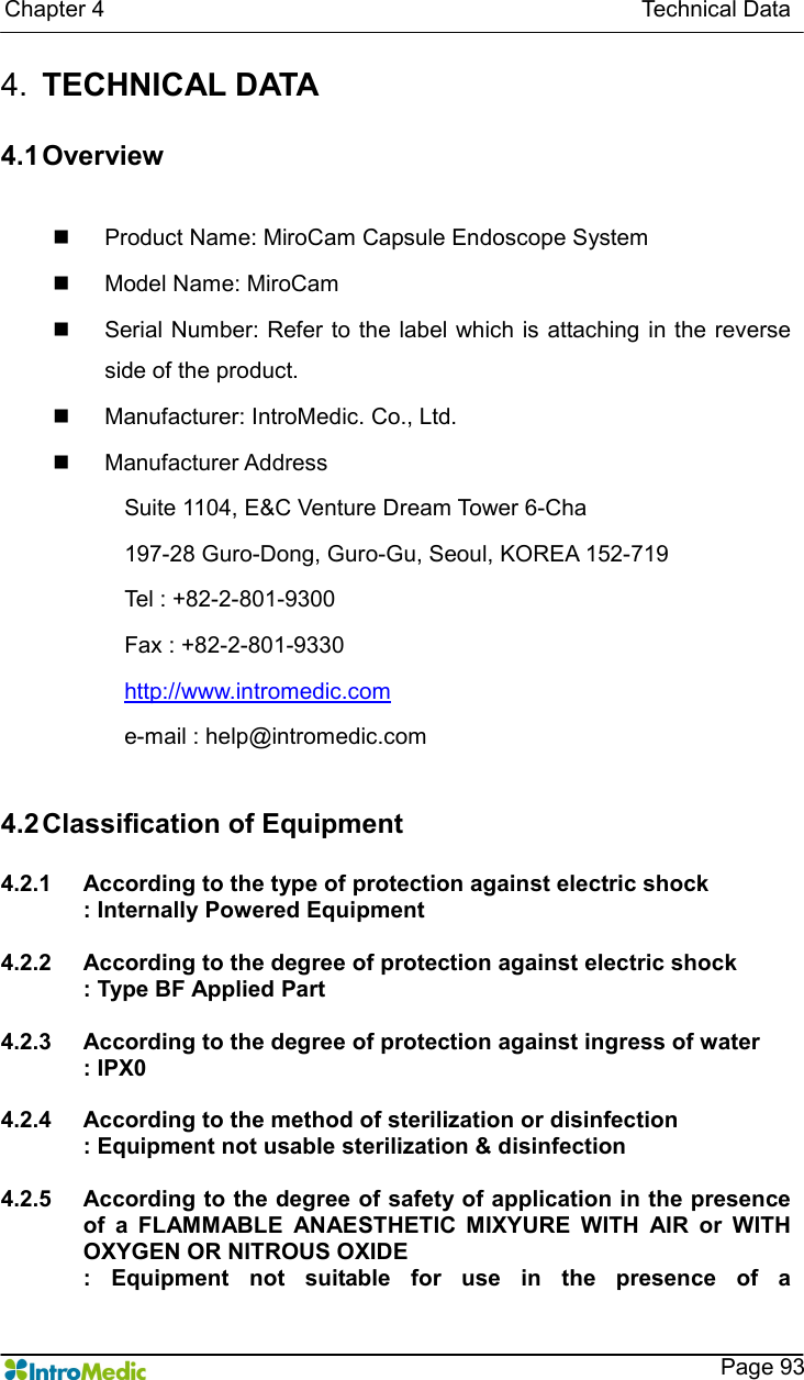


![EMC Information Chapter 8 Page 128 survey, a should be less than the compliance level in each frequency range. b Interference may occur in the vicinity of equipment marked with the following symbol : NOTE 1 ) At 80MHz and 800MHz, the higher frequency range applies. NOTE 2) These guidelines may not apply in all situations. Electromagnetic propagation is affected by absorption and reflection from structures, objects and people. a Field strengths from fixed transmitters, such as base stations for radio (cellular/cordless) telephones and land mobile radios, amateur radio, AM and FM radio broadcast and TV broadcast cannot be predicted theoretically with accuracy. To assess the electromagnetic environment due to fixed RF transmitters, an electromagnetic site survey should be considered. If the measured field strength in the location in which the EUT is used exceeds the applicable RF compliance level above, the EUT should be observed to verify normal operation. If abnormal performance is observed, additional measures may be necessary, such as re-orienting or relocating the EUT. b Over the frequency range 150kHz to 80MHz, field strengths should be less than [V1] V/m.](https://usermanual.wiki/Intromedic/INTROMEDIC2.User-Manual-2/User-Guide-1106185-Page-134.png)
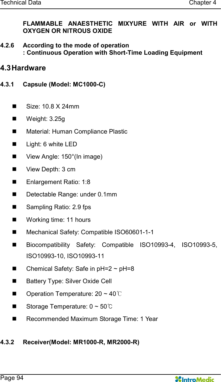
![Chapter 8 EMC Information Page 129 8.4 Recommended separation distances between portable and mobile RF communications equipment and the EUT Intended for use in an electromagnetic environment in which radiated RF disturbances are controlled. The customer or the user of the EUT can help prevent electromagnetic interference by maintaining a minimum distance between portable and mobile RF communications equipment (transmitters) and the EUT as recommended below, according to the maximum output power of the communications equipment. Separation distance according to frequency of transmitter[m] 150kHz to 80MHz 80MHz to 800MHz 800MHz to 2.5GHz Rated maximum output power of transmitter [W] V1=3Vrms E1=3V/m E1=3V/m 0.01 0.116 0.1166 0.2333 0.1 0.368 0.3687 0.7378 1 1.166 1.1660 2.3333 10 3.687 3.6872 7.3785 100 11.660 11.6600 23.333 For transmitters rated at a maximum output power not listed above, the recommended separation distance d in metres (m)can be estimated using the equation applicable to the frequency of the transmitter, where p is the maximum output power rating of the transmitter in watts (W) according to the transmitter manufacturer. NOTE 1) At 80MHz and 800MHz, the separation distance for the higher frequency range applies. NOTE 2) These guidelines may not apply in all situations. Electromagnetic propagation is affected by absorption and reflection from structures, objects and people.](https://usermanual.wiki/Intromedic/INTROMEDIC2.User-Manual-2/User-Guide-1106185-Page-135.png)