Intromedic INTROMEDIC2 Capsule Endoscope & Receiver User Manual 2
Intromedic Co., Ltd. Capsule Endoscope & Receiver 2
Contents
- 1. User Manual 1
- 2. User Manual 2
User Manual 2

Copyright© 2007 IntroMedic Co., Ltd. MM1100-0807
Version 1.22 Date : 2008-07-01
Service Manual

Warranty
Page 3
Trademarks
MiroCam®, MiroView™, IntroMedic, and the associated logos are the
registered trademarks ® or trademarks ™ of IntroMedic Co., Ltd. © IntroMedic
Co., Ltd. July 2007.
Except as required by applicable copyright laws; any use of the IntroMedic
trademarks, or any reprinting, reproduction, modification, referencing and
translations of the User Manual, without the prior written approval of
IntroMedic Co., Ltd. is strictly prohibited.
Warranty
Every effort has been made to ensure the information contained in this
Service Manual is accurate, and is believed to be correct at time of printing.
IntroMedic reserves the right to change any content contained with this
Service Manual without prior notice.
IntroMedic Co., Ltd. warrants the product against defects in material and
workmanship for a period of twelve (12) months from the date of sale, unless
different local regulations apply. IntroMedic Co., Ltd. will repair or replace
products that are ascertained by IntroMedic to have defects during the
warranty period. IntroMedic Co., Ltd. is not liable for the defects occurred by
misuse, careless handling, unauthorized modifications or erroneous use, or
any use that is non-compliant with instructions detailed within this Service
Manual. This includes use of the product in non-appropriate locations or
conditions. Any other warranties are neither represented here nor recognized
by implication.
To validate the warranty, please complete product registration with the local
authorized IntroMedic distributor.

Warranty
Page 4
Exclusive warranty service
The warranty service provided hereby is applicable exclusively to the
purchaser of the product. IntroMedic will only warranty the product for
purposes and usage as defined in this Service Manual. Any usage not
heeding the warnings, cautions and recommended usages as defined in this
manual will nullify the warranty.
Support
For warranty or repair service please contact the local authorized IntroMedic
distributor.
For customer service or support please contact your point of purchase or
IntroMedic Co., Ltd. Service agreements are only applicable to products of
IntroMedic Co., Ltd.
IntroMedic Customer Service
TEL: 82-2-801-9300
FAX: 82-2-801-9330
http://www.intromedic.com
E-mail: helpdesk@intromedic.com
Safety
Non-compliance with the user’s manual, unauthorized modifications of the
product or replacement of parts, and/or opening of the product casing is
prohibited and may be hazardous.

Contents
Page 5
Contents
1. SYSTEM OVERVIEW ................................... 3
1.1 Warnings ............................................................. 3
1.2 Symbols for Safety ............................................... 4
1.3 Function Symbols ................................................ 5
1.4 Remarks for Safe Use .......................................... 8
2. SYSTEM OVERVIEW ................................. 19
2.1 MiroCam® Overview .......................................... 19
2.2 MiroCam System Main Components ................... 20
2.3 MiroCam® Method of Action .............................. 21
2.4 System Configuration......................................... 23
2.5 Product Specifications....................................... 27
2.6 Component List.................................................. 37
3. PRODUCT INSTALLATION ....................... 41
3.1 Component Check List ....................................... 41
3.2 Packaging Specifications................................... 42
3.3 Installation Diagram ........................................... 45
3.4 System Installation & Connection....................... 46
3.5 MiroView™ Installation....................................... 50
4. TECHNICAL DATA..................................... 93
4.1 Overview............................................................ 93
4.2 Hardware........................................................... 93
4.3 Software ............................................................ 96
4.4 Compliance / Approvals ..................................... 98

Contents
Page 6
5. Storage & Transportation .................. 103
5.1 Safe Storage Conditions ...................................103
5.2 Safety Transportion Conditions.........................103
6. TROUBLESHOOTING.............................. 107
6.1 Introduction ......................................................107
6.2 Who should perform repairs..............................107
6.3 Obtain replacement parts .................................107
6.4 Troubleshooting Guide......................................108
7. PACKING FOR SHIPMENT...................... 115
7.1 General Introduction.........................................115
7.2 Repacking in Original Packing Box ....................115
7.3 Repacking in Different Packing Box...................121
8. EMC INFORMATION................................ 125

1
Safety Information

Safety Information Chapter 1
Page 2

Chapter 1 Safety Information
Page 3
1. SYSTEM OVERVIEW
1.1 Warnings
MiroCam® has been manufactured to conform with the International
Standard for Medical Electrical Equipment: General Requirements for
Safety IEC 60601-1, together with the Collateral Standard for
Electromagnetic Compatibility Requirement and Tests IEC 60601-1-2.
MiroCam® has been manufactured to conform to the electric shock, fire
and mechanical hazard standards as defined in CAN/CSA C22.2
NO.601.1.
Based on request of the buyer, IntroMedic will provide the labeling, such
as ID labels, and the User & Service Manual in the national language(s)
of European countries. Translated documents will be evaluated by a local
language expert, and will be confirmed by a native speaker of the
respective national language.
Safety Symbols: The User & Service Manual incorporates various safety
symbols to ensure safe and correct use of the product and to prevent any
personal injury or property damage. These symbols are defined in the
following table:
WARNING
WARNING indicates a potential hazard that, if not avoided, could
result in serious personal injury or damage to the product.
CAUTION
CAUTION indicates a potential hazard that, if not avoided, could
result in minor personal injury or damage to the product.
NOTE
NOTE does not indicate potential hazards as in Caution or
Warning, but contains important information regarding the
installation, operation or maintenance of the product.
Safety Information Chapter 1
Page 4
1.2 Symbols for Safety
This section describes a set of symbols that IEC (The International
Electrotechnical Commission) has established for medical electronic
equipment to classify a connection or warning of any potential hazards.
IEC 348: Notice for the user to pay special attention to the
following details
IEC 878-02-03: Indicates that this is classified into Type BF
equipment
EN 980: Denotes Date of Manufacture
EN 980: Denotes Address of Manufacture
IEC60601, ANNEX D: Denotes “ON” status of main power
switch
IEC60601, ANNEX D: Denotes “OFF” status of main power
switch
SN EN 980: Denotes serial number
IEC 417-5031: Denotes DC (Direct Current)
IEC 417-5032: Denotes AC (Alternating Current)
A Denotes Ampere, the unit of current
V Denotes Volt, the unit of Voltage
Hz Denote Herz, the unit of Frequency
IEC 417-5021: Denotes potential equalization terminal
Single Use Only
Use by date
Chapter 1 Safety Information
Page 5
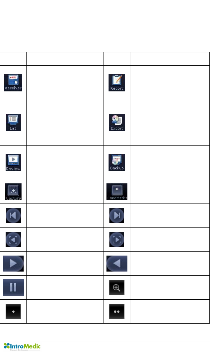
1.3 Function Symbols
1.3.1 Application Function Symbols
The following table describes symbols or icons used in the
MiroView™ software.
Symbol Description Symbol Description
Connect to the receiver
and open receiver control
screen.
Open the report screen to
create a patient capsule
endoscopy report.
Open the patient data
screen of the MiroCam®
system.
Open screen to export
(save externally) selected
image data for a specific
patient.
Opens screen to view
MiroCam ® for a specific
patient.
Open screen to backup
image data for a specific
patient.
Select and save an image
being reviewed.
Place a landmark in an
image being reviewed.
Move to the previous
image. Move to the next image.
Move to the previous
captured image.
Move to the next captured
image.
Play images in sequential
order.
Play images in reverse
order.
Stop playback of images. Zoom images.
Show images in a single
screen.
Show images in the dual
screen.
Safety Information Chapter 1
Page 6
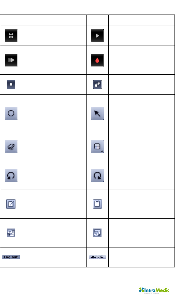
Symbol Description Symbol Description
Show images in the quad
screen. Play all images.
Play the selected images
only. View images via
Quick Mode function.
SGIB - Play the images
captured via Suspected GI
Bleeding function.
Show images in the
Capture Box by group.
Show all images in the
Capture Box.
When editing the captured
image in the report mode,
add a circle on the
captured image.
When editing the captured
image in the report mode,
add an arrow on the
captured image.
Erase the circle or arrow
displayed in an image
when a report is created.
Select a color to use in an
image when a report is
created.
Cancel the last action
applied to an image when
a report is created.
Re-apply the cancelled
changes when a report is
created.
Indicate that a report for
the selected patient is
being created.
Indicate that a report for the
selected patient has been
created.
Indicate that image data for
the selected patient has
been exported.
Indicate that image data for
the selected patient has
been backed up.
User logs out from
MiroView™.
Show the complete list of
patients

Chapter 1 Safety Information
Page 7
1.3.2 Receiver Function Symbols
Symbol Description
SIG Indicates status of signal from capsule
Green: Signal is being received from capsule
Yellow: Signal is not being received from capsule
INI Initialization status of Receiver Unit
Green: Receiver is initialized
Yellow: Receiver is not initialized
BAT
Battery Status
Green: Fully charged
Yellow: Not charged

Safety Information Chapter 1
Page 8
1.4 Remarks for Safe Use
n Follow the safety instructions included in this Service Manual and
clinical precautions advised by medical professionals.
n The manufacturer is not liable for harm or damage caused by improper,
unauthorized, unprofessional or inexpert use of the device and/or
product.
n IntroMedic Co., Ltd. is NOT responsible for physical harm or
equipment problems caused by the user’s careless operation or
mismanagement of the device and/or product.
n Users MUST have read and understood the User Manual. ONLY
trained and qualified medical professionals or authorized
representatives of IntroMedic Co., Ltd. may operate the system.
n User Manual must ALWAYS be with the equipment. This is the USER’S
RESPONSIBILITY.
n CAUTION: The equipment should not be exposed or come in contact
with foreign substances including water, cleaning fluids, disinfecting
cleanser; as such substances may harm the equipment
n ONLY authorized personnel may perform repairs. Never attempt to
open covers, panels or casings.
n DO NOT crease, bend, fold or twist the data cables. Take care to
guard them against mechanical stress (e.g. wheels or heels)!
n The sensor pads, receiver, data cables, and capsules must not be
exposed to mechanical shock (e.g. by dropping). Any damage caused
will void the product warranty.
n CAUTION: Damage/injuries to the sensor pad or data cable may cause
a safety hazard. Damaged items MUST be repaired IMMEDIATELY.
n DO NOT handle fluids in the vicinity of the system.
n When using a cart, ensure the brake or latch guard is in use to prevent
the cart from rolling.
n DO NOT USE in moist or damp places.

Chapter 1 Safety Information
Page 9
n DO NOT operate the equipment with wet hands.
n Avoid using the equipment in extreme temperatures or humid
environments.
n DO NOT keep the equipment or carry out the procedure in places such
as areas exposed to direct sunlight, vicinity of heaters, vicinity of
chemical materials or gases, areas moist/damp or dusty, or poorly
ventilated areas.
n DO NOT disassemble or open the equipment without permission. This
will invalidate the warranty.
n DO NOT carry out the procedure in areas with high vibrations or in
environments where high electro-magnetic waves are generated.
n DO NOT pull out the power cord by grabbing the cable. When
disconnecting the power cord, grasp the plug, and pull out. This
prevents short-circuits, disconnection, or cord damage.
n CAUTION: Verify that the power voltage supplied from the power
receptacle matches with the voltage the system requires. Check
Voltage and Frequency on the AC/DC adaptor.
n CAUTION: Verify that all connection terminals are securely connected
to the system.
n CAUTION: Turn off the power switch on the receiver before connecting
the sensor pads.
n DO NOT discard cables and connectors with general waste. Discard
separately as industrial or medical waste.
n CAUTION: Discard the battery according to the regulations of industrial
waste. DO NOT discard with general waste.
n The capsule and sensor pads are medical waste, and should be
disposed of according to local regulations or WEEE directive on waste
disposal.
n DO NOT carry out the procedure simultaneously with other procedures
using medical products or equipment.

Safety Information Chapter 1
Page 10
n DO NOT use for purposes other than medical treatment.
n DO NOT connect the USB cable to the receiver while the receiver’s
data cable and sensor pads are still connected.

Chapter 1 Safety Information
Page 11
n DO NOT charge the receiver while the receiver’s data cable and
sensor pads are still connected.
n Connect USB cable to receiver only after mounting it on charger.
n DO NOT install any other programs onto the workstation utilized for
review and diagnosis of patient image data (i.e computers with the
MiroView™ software).
n The capsule is disposable and should not be reused.
n In the medical environment condition, only use the capsule, receiver,
data cable and sensor pads.
n All products connected with the MiroCam® Endoscope system must
be compliant with requirements of IEC60950-1 or UL certifications.
Safety Information Chapter 1
Page 12
1.4.1 Environmental Condition for Operation
n Temperature : +10 ℃ - +40℃
n Relative humidity : 45% - 75%
n Atmospheric pressure : 700hPa to 1060hPa
WARNING DO NOT operate the equipment in the vicinity of
generators, power stations, X-ray devices, and
broadcasting stations where high levels of electro-magnetic
waves are generated. The electro-magnetic waves can
cause equipment malfunctions.
CAUTION If the equipment has been brought in from a cold
environment (stock room, airfreight) into a warm room,
initial activation should take place after a few hours, to
allow for temperature adjustment and balance and
evaporation of condensed humidity.
WARNING DO NOT operate the equipment in the vicinity of heat
sources, strong electric or magnetic fields (close to a
transformer), or near instruments generating high-
frequency signals.
WARNING Do not use MiroCam® alongside or together with medical
devices or procedures involving electrical currents.
Do not use MiroCam® with h.f. surgical equipment. It may
result in burns at the site of the electrodes and possible
damage to the capsule and receiver.
Do not use the unit in close radius (within 1 m) of short
wave or microwave therapy equipment. It may produce
instability in the captured image.
WARNING This device is a Class B device according to EN60601-1-2
standards. This equipment can cause radio interference in
residential areas. In this case, the owner (or operator) can
be held responsible to take appropriate measures or take
proper measures for compensation.

Chapter 1 Safety Information
Page 13
1.4.2 Safety Precaution
CAUTION - Make sure the environment is without interference from
electromagnetic fields.
- Make sure the environment is without noise and
vibration.
- DO NOT carry out the procedure while using other
equipments, devices or products.
- The instruction for use of the sensor pads MUST be
observed.
- DO NOT use on patients with pacemakers or
defibrillators.
CAUTION DO NOT use the capsule if the package is unsealed.
n DO NOT reuse capsules.
n To prevent unexpected accidents like fire or explosion, do not use any
product near or in the presence of inflammable or ignitable substances.
n DO NOT disassemble the equipment case nor open the cover. In case
service is required, please contact IntroMedic customer support or
local point of sale immediately.
n Only the accessories authorized and designed by IntroMedic Co., Ltd.
should be used with this equipment. Faults resulting from the usage of
unapproved or inappropriate accessories are not guaranteed against.
n This equipment may have an effect on other products or be effected by
other products.
n Follow the Doctor’s instructions and abide by the guidelines in the User
Manual.
n DO NOT try to upload the data while the data cables are still
connected to the receiver.
n DO NOT charge the rechargeable battery in the receiver while the data
cable and sensor pads are still connected to the receiver.

Safety Information Chapter 1
Page 14
n Stay away from high frequency radiation sites (such as high voltage,
radar, installation power plants, MRI, CT or electric blankets etc.)
during your capsule endoscope procedure. (It may result in serious
side effects requiring emergency treatment.)
n In case of any symptoms of abdominal pain, vomiting, fever, heart
trouble, dizziness or seizure during or after the capsule endoscope
procedure, the patient should immediately notify the physician in
charge.
n Always check the connection between the receiver and the data cable.
n Always check that the battery in the receiver is fully charged before
use.
n DO NOT use the capsule if the package is unsealed.
n After ingesting the capsule, ask patient to check whether the capsule
has been excreted.
n Prior to undergoing the capsule endoscopy procedure, patients with
diabetes must be informed via a medical professional regarding
appropriate medication & dosage.
n For more accurate data and better analysis, follow the Patient
Preparation as recommended in the User’s Manual.
n Tell Patient not to bite the capsule before ingesting.
n Patient should avoid excessive physical activity during the capsule
endoscope procedure.
n When undergoing the capsule endoscope procedure, DO NOT make
physical contact with another person undergoing the same procedure.
n During operation of the receiver, DO NOT touch the receiver, or get the
receiver wet.
n Only use the provided batteries, and never remove the battery from the
receiver during the procedure.
n During upload of the data recorded in the receiver to the PC, avoid
disconnecting the USB. This may damage the patient’s data.

Chapter 1 Safety Information
Page 15
n Always confirm that the USB is connected by checking the Receiver
screen on the MiroView™ software.
n Always check the AC Power range before use the workstation.
n DO NOT touch AC Power code with wet hands.
n DO NOT open the receiver bag or touch receiver outside of the
hospital.
n This device is intended for the patients over the age of 18.
WARNING The Capsule takes images for 11 hours and gets naturally
excreted in about 24 hours under normal conditions. If the
capsule has not been excreted from the patient within 72
hours, patient should contact the physician. After
examining, the physician may need to perform a surgical
operation or treatment to remove the capsule.
WARNING Before moving the system, always make sure to disconnect
the monitor from the main system, and then safely move
the main system and monitor separately. Connect the main
system and monitor only after the hardware is fully
installed, secure and stable.

Safety Information Chapter 1
Page 16
1.4.3 Cleaning and Maintenance
n System and accessories
- All products should be cleanly maintained. For cleaning, rub lightly
with a soft cloth wet with warm water at least once a week. Do not
use organic solvents such as lacquer, thinner, ethylene and oxide
because they can damage the equipment. Be careful that foreign
substances do not enter the main system when cleaning.
- ALWAYS operate the equipment under sanitary environmental
conditions. DO NOT use heat or gas for disinfection of the capsule.
n Service Document
If required, or upon request, the local IntroMedic Distributor (authorized
IntroMedic Representative) may provide block diagrams, lists of spare
parts, descriptions, adjustment instructions or other related information
which may help qualified technical personnel in repairing specified
parts of the equipment which have been defined repairable by
IntroMedic Co., Ltd. .
n Moving the Equipment
- CAUTION when moving equipment.
- WARNING: Excessive impact/shock causes internal damage.
- If wiring is connected/disconnected when moving, check the wiring
status after moving.
- If damage to the equipment is discovered after moving, immediately
contact IntroMedic or local Distributor.

2
System Overview

System Overview Chapter 2
Page 18

Chapter 2 System Overview
Page 19
2. SYSTEM OVERVIEW
2.1 MiroCam® Overview
MiroCam® is an orally ingested capsule endoscope designed to capture
images of the small intestine lining. Captured images are viewed via the
MiroCam® software for diagnosis of diseases related to the small
intestine. Generally, the capsule endoscope has been developed to
provide a means to view the entire small bowel, with much higher
diagnostic sensitivity than other radiological techniques. Further, the
capsule endoscope avoids a great deal of discomfort associated with
traditional endoscopy, while allowing the patient to maintain a normal
schedule.
Additional methods for screening of the small bowel primarily include
barium x-rays and enteroscopy, but the diagnostic value of these tests for
a wide variety of specific lesions is low. Following is further description of
the methods.
Enteroscopy is a method to perform direct visual inspection of the small
bowel mucosa beyond the reach of standard upper endoscopes. The
procedure can be accomplished of the small by examination with either
push or sonde type endoscopes, or operative enteroscopy. Enteroscopy
of the small intestine is difficult, requires a lengthy examination time, can
only partially visualize the small intestine, is extremely uncomfortable,
and is not performed on a widespread basis.
Barium X-rays of the small bowel are currently the primary radiographic
means of diagnosing a small bowel neoplasm, and the best way to locate
small bowel lesions. However, the procedure has limited sensitivity.

System Overview Chapter 2
Page 20
Sensitivity to diagnose small bowel neoplasms can be doubled by
enteroclysis, which is extremely inconvenient for the patient and must be
done only in a hospital set up by an expert. The sensitivity and specificity
of the diagnosis of mucosal lesion (like AVM, for example) is close to
zero.
Computed tomography (CT) of the abdomen is sometimes helpful in
diagnosing and localizing of small bowel abnormalities, but it is unable to
determine small intraluminal or mucosal lesions.
It is widely accepted that the aforementioned methods for diagnosing
small bowel diseases and disorders are limited. Capsule Endoscopy is a
great advancement, providing a much more thorough diagnostic method.
IntroMedic’s MiroCam Capsule Endoscope System is designed to aid the
gastroenterologist in visualizing and diagnosing disease of the small
bowel in an efficient, cost effective, and comfortable manner. .
2.2 MiroCam System Main Components
— Capsule:The MiroCam Capsule moves slowly through the small
intestine tract, capturing images of the entire small intestine at 3
frames/sec.
— Receiver:The MiroCam Receiver provides 9 receiving channels
through which signals can be received. The pair of channels which
have the best signal characteristics are selected and used for the
receipt of the of image signals. The receive also connects to
MiroView™ software to upload images taken of the patient’s GI
tract.
— MiroView™ Software: MiroView™ enables the gastorenterologist
to perform a diagnostic reiview of the patient’s small bowel, and
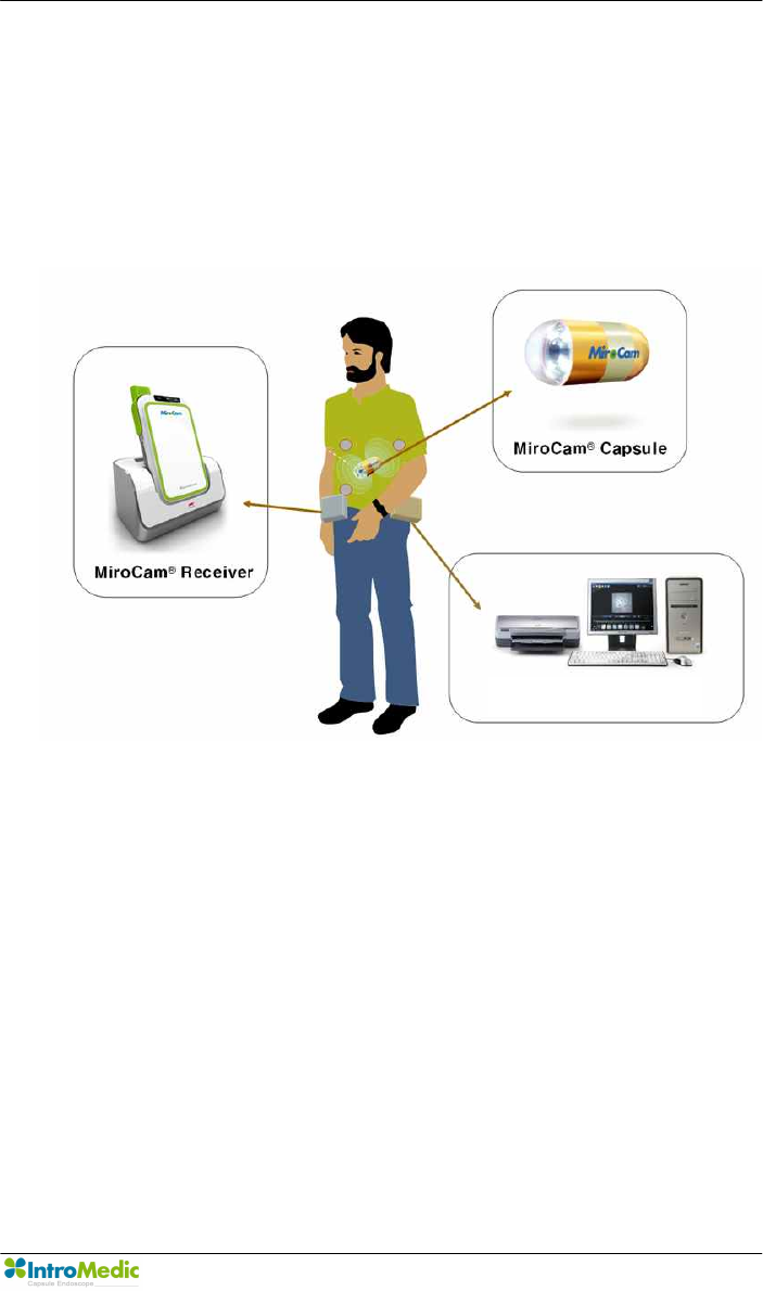
Chapter 2 System Overview
Page 21
document the results in a printable report.
2.3 MiroCam® Method of Action
The following image displays the key components of the MiroCam
capsule endoscope system.
To enable physicians to diagnose images of a patient’s small bowel, the
MiroCam method of action includes the following steps.
Step 1. Image Capturing: The MiroCam capsule uses a CMOS Image
sensor built in the capsule to take the pictures through the front of the
optical dome. The LED light flashes each time the picture is taken to
brighten the dark digestive organ. The capsule captures 3 pictures per
second and sends the images to the receiver immediately. For
transmission, the images taken from the capsule are transformed to
data that is possible to transmit to the receiver through the human body.
MiroView™

System Overview Chapter 2
Page 22
Step 2. Data transmission: The MiroCam capsule transmits the data
from the capsule via E-Field Propagation. This communication method
uses the human body as the medium to transmit signals from internally
within the body (from the capsule) to external sensors (data cable
sensor pads).
Step 3. Data Reception and Storage: To retrieve the signal emitted
from the capsule, the MiroCam system needs to attach reception poles
(sensors attached to data cables) on the exterior of the human body to
retrieve the signal. The signal is then changed into a data format that is
feasible for image processing, and stored onto the memory of the
receiver.
Step 4. Data Upload: The image data is uploaded from the receiver to
the MiroView software (software on a PC workstation) via a standard
USB data cable. This data is uploaded after the patient has completed
the procedure (i.e. sensor pads / data cables are not attached to
patient).
Step 5. Image Restoration & Display: After all stored image data in
the receiver has been transferred to the image processing software
(MiroView™), the software changes the transferred image data by using
an image reconstruction algorithm to a RGB signal. The reconstructed
image data is saved along with patient information, and viewed by the
physician to diagnose diseases of the small bowel. MiroView™ can
recall the saved data anytime, as the user desires to perform a
diagnostic review of the patient images.
Chapter 2 System Overview
Page 23
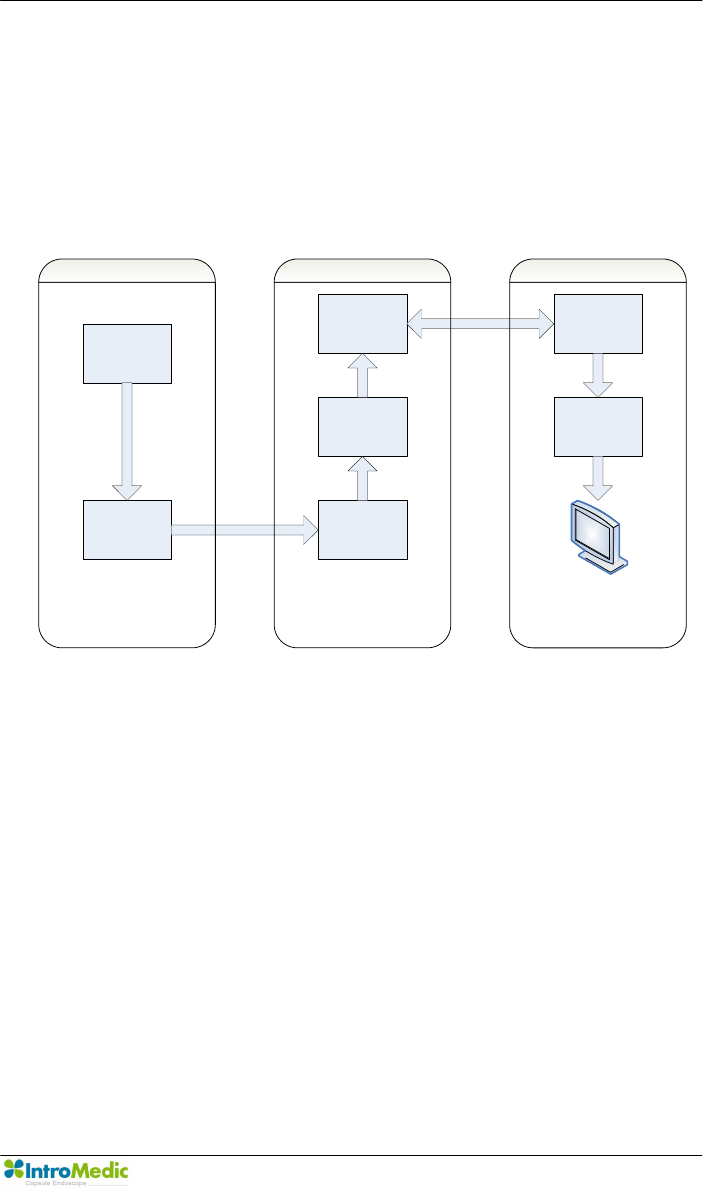
2.4 System Configuration
The MiroCam® System consists of an imaging capsule, signal receiver,
and the MiroView™ software for image viewing. The overall system
configuration is as follows:
Image Sensor
Data Transmiter Data Recover
Data Storage
System Interface Data
Communication
Image
Processing
Image Display
Capsule Receiver Software
MiroCam System Block Diagram
System Overview Chapter 2
Page 24
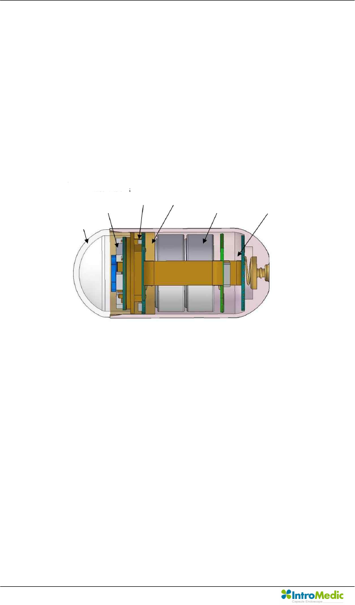
2.4.1 Capsule
The capsule consists of an optical dome, LED module, imaging &
communication module, battery, power supply module, cage pin and
cage. The capsule can operate inside a human body for more than 11
hours. This mechanical device is enclosed in a harmless plastic
capsule. The dome and the capsule body are bonded with a medical
grade adhesive. The surface of the plastic body is gold-plated for
signal transmission.
<Capsule Structure>
CMOS Image Sensor Specifications
· Image size : 320 * 320 pixel
· Operation voltage : 3V
· Operation Frequency :12MHz
· Image Frame : 3 Frame / sec
2.4.2 Receiver
The MiroCam® Receiver consists of the data cable, signal input
block, analog block, digital control block, data storage block and USB
communication block. Following is some more information about the
Power supply
LED module
Lenz module
Dome
PCB sensor
Battery

Chapter 2 System Overview
Page 25
individual components.
u Signal input block includes 9 channel connectors and a
multiplexer
u Analog block has an amplifier and filter for analog to digital
conversion. This converts the image data transmitted by the
capsule.
u Digital control block includes a digital image processing unit
and demodulation unit. This block also saves the data.
u All image data is saved to flash memory and transferred to
image processing workstation by USB channel
u The receiver is divided into a restoration part that restores
the actual data, and a transmitter part that transmits the
image data to MiroView™. More specifically, the receiver
can be divided into the receiving block, signal input block,
analog block, digital block, storage block and USB
transmission block. After processing the converted signals,
the digital block demodulates image data and saves it. The
saved data is then transferred to MiroView™ software (on a
PC) via the USB transmission module.
Receiver Power Source: The MiroCam receiver operates via a
battery, completely independent of any other power sources.
The receiver of the MiroCam® capsule endoscope system includes
amplifier and filter components, which convert the image data
transmitted by the capsule. The receiver is divided into a restoration
part that restores the actual data, and a transmitter part that
transmits the image data to MiroView™. More specifically, the
receiver can be divided into the receiving block, signal input block,
analog block, digital block, storage block and USB transmission

System Overview Chapter 2
Page 26
block. The signal input block is implemented with 9 signal lines and
connectors while the analog block amplifies, filters and performs AD
conversion. After processing the converted signals, the digital block
demodulates image data and saves it. The saved data is then
transferred to MiroView™ software (on a PC) via the USB
transmission module.
2.4.3 MiroView™ (Software)
MiroView™, the application software for the MiroCam® capsule
endoscope system, consists of an image-processing module that
restores the received image data to actual images, and an output
module for image output.
The recorded images can be viewed via a conventional PC or
Notebook using IntroMedic’s proprietary software. MiroView™ is
compatible with Windows operating systems. Selected images can
be edited and saved in a CD or DVD.
The software includes a number of features and functions to assist
in the efficiency and sensitivity of the diagnosis.
Chapter 2 System Overview
Page 27
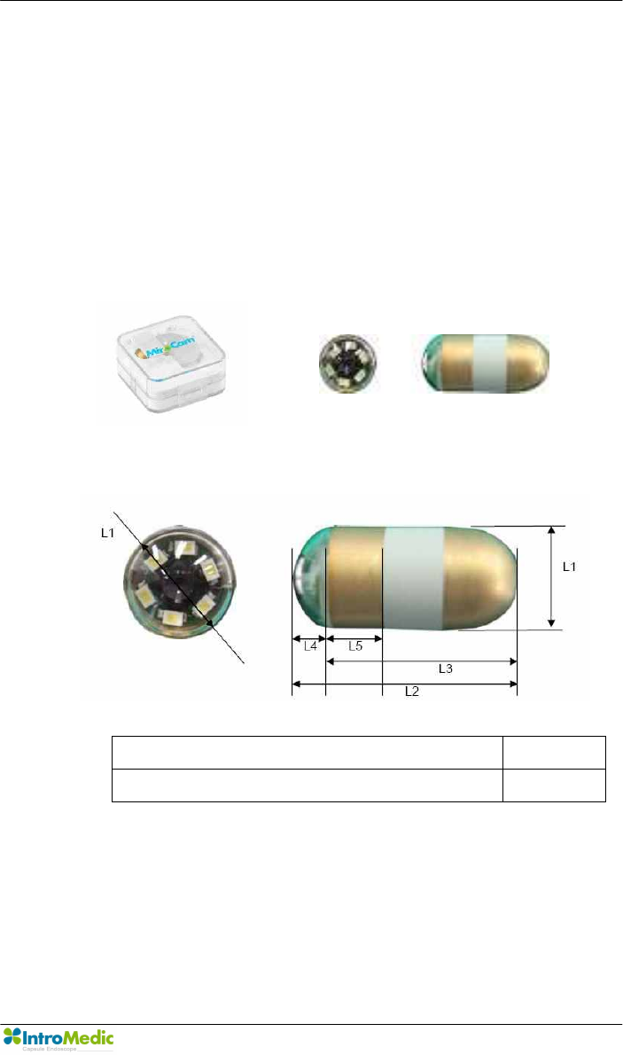
2.5 Product Specifications
2.5.1 Capsule
Capsule consists of the optical dome, lens, led lighting module,
gold-band, battery, power module, case pin and case. The capsule
operates for about 11 hours in the human body. The electrical
components are enclosed by a plastic cage that is safe and does
not harm the human body.
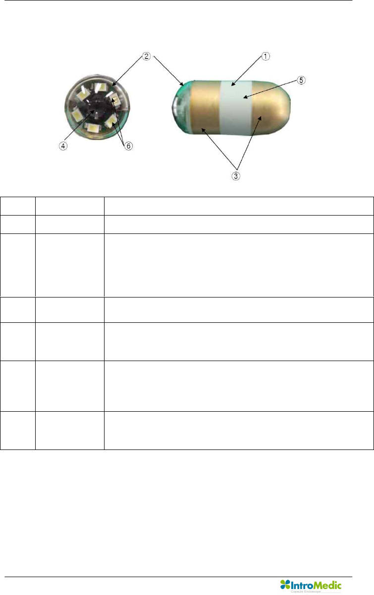
n Dimensions
Size(mm) Weight(g)
10.8(L1) x 24(L2) x 19(L3) x 5(L4) x6(L5) 3.25
System Overview Chapter 2
Page 28
n Description
No. Title Function
1 Main Body - Main Device of MiroCam MC1000
2 Optical
Dome
- This transmits light from the outside of Capsule
and its transparency is over 98%.
- Made from COC.
- This transmits light source of image from the LED
of inside of capsule.
3 Gold-Band - Gold coating that transmits the image data from
the capsule to the human body.
4 Lens - The lens concentrates the light emitted by the
LEDs, and focuses the image for the CMOS
image sensor.
5 Cage - Protects the interior capsule components.
- Prevents entry of foreign materials into capsule.
- Cage is composed of an FDA certified safe
material, harmless to the human body.
6 White LED - LED illuminates the dark spaces inside the
human body GI tract.
- The illumination enables images to be captured.

Chapter 2 System Overview
Page 29
n Specifications
- Size : 10.8 X 24mm
- Weight : 3.25g
- Material : Human Compliance Plastic
- Light : 6 white LED
- View Angle : 150°(In image)
- View Depth : 3 cm
- Enlargement Ratio : 1:8
- Detectable Range : under 0.1mm
- Sampling Ratio : 2.9 fps
- Operating time : 11 hours
- Mechanical Safety : Compatible ISO60601-1-1
- Biocompatibility Safety : Compatible ISO10993-4, ISO10993-5,
ISO10993-10, ISO10993-11
- Chemical Safety : Safe in pH=2 ~ pH=8
- Battery Type : Silver Oxide Cell
- Operation Temperature : 20 ~ 40℃
- Storage Temperature : 0 ~ 50℃
System Overview Chapter 2
Page 30
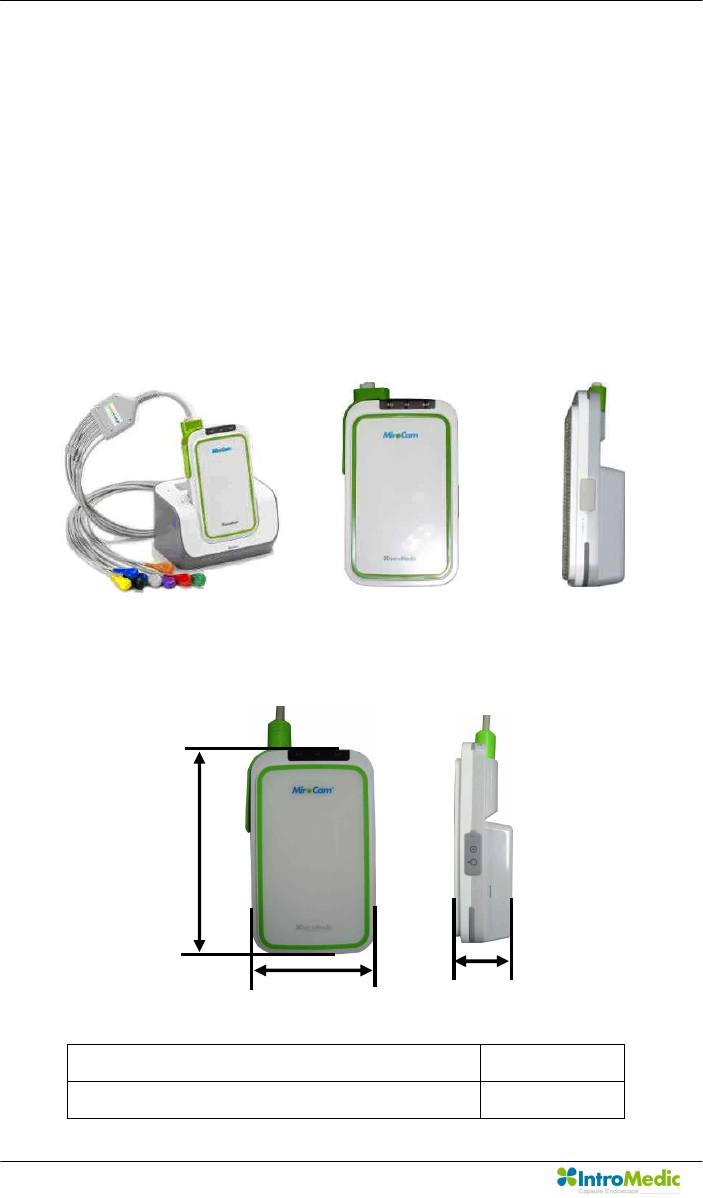
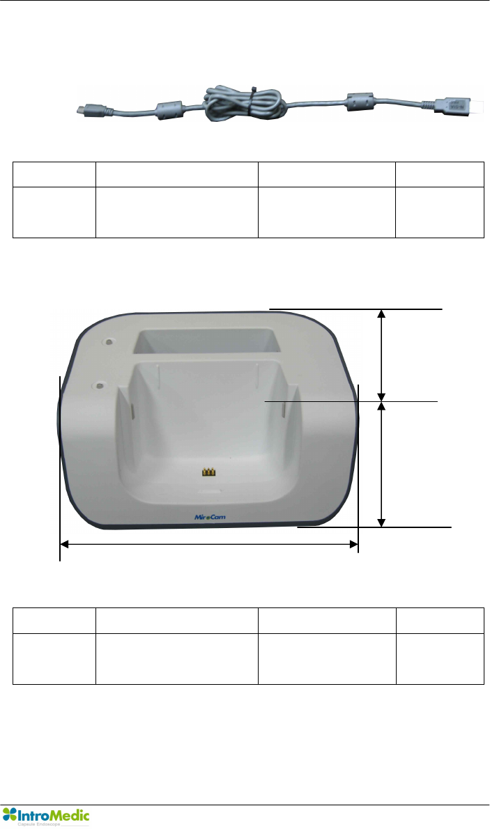
2.5.2 Receiver
Receiver consists of the data cable, signal input block, analog block,
digital control block, data storage block and USB communication
block. Signal input block has 9 channel connectors and a multiplexer.
Analog block has an amplifier and filter for analog to digital
conversion. Digital control block has a digital image processing unit
and demodulation unit. All image data are saved to flash memory
and transferred to image processing workstation by USB channel.
n Dimensions
Size(mm) Weight(g)
140(H) x 85(W) x 40(L) 350
H
W
L
Chapter 2 System Overview
Page 31
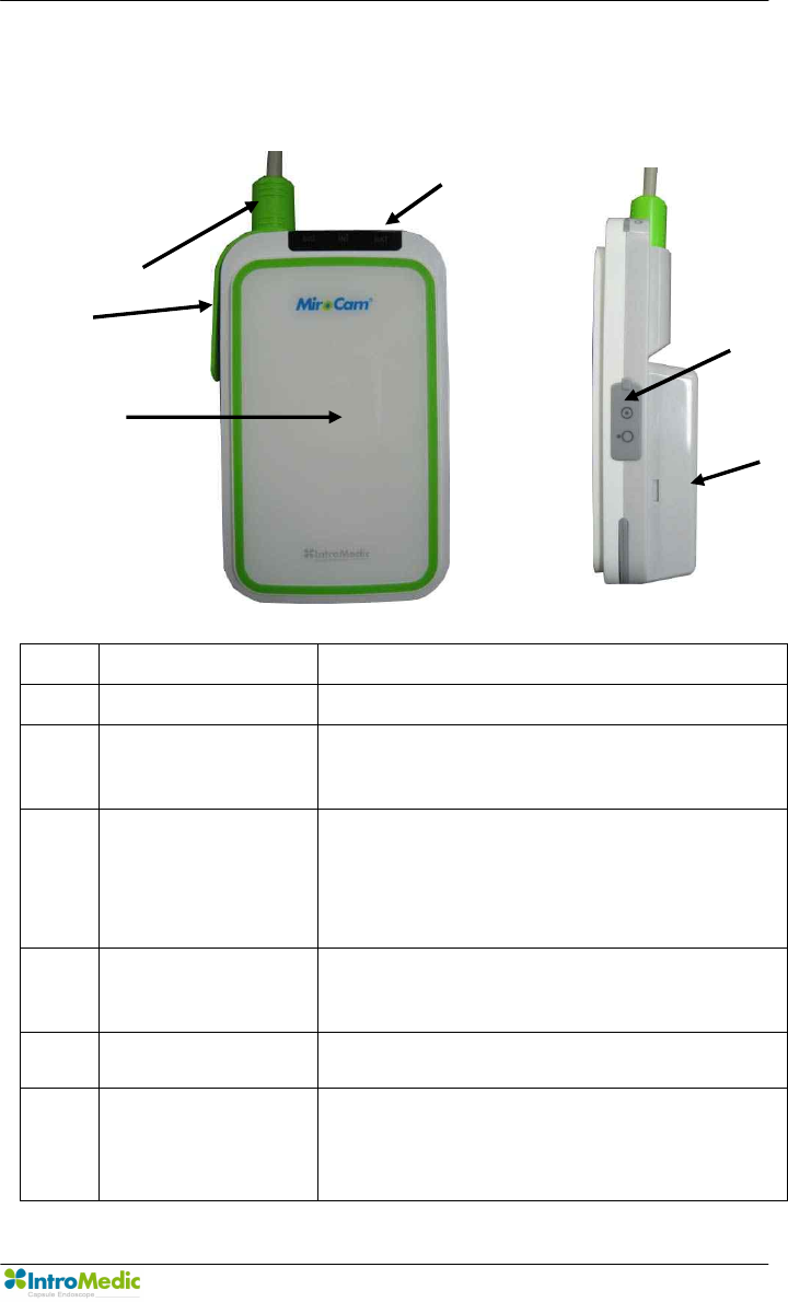
n Description
No. Title Function
① Main Body - Main Device of MiroCam MR1000.
② 9-Channel
Connector
- Durable connector to deliver the
signal from the data cables to the
receiver.
③ LED Display - Display status of Receiver.
- Signal display to indicate normal
operation, including battery,
initialization status and signal
reception.
④ USB Connector - USB Communication connector for
image data transmission to Image
processing workstation.
⑤ Power Switch - Turn Main power of Receiver on or
off.
⑥ Battery - Rechargeable battery for MiroCam
Receiver unit.
- Output voltage : 3.7Vdc
- Output Current : 8.8A
‚
ƒ
„
…
†

System Overview Chapter 2
Page 32
n Specifications
- Operation System : Firmware
- Recording Time : 12 Hours
- Weight : 350g, include battery
- Operation Voltage : 3.7V, 0.45A
- Battery Type: Lithium Ion Battery (3.7V, 8.8A)
- Battery Weight : 215g
- Operation Temperature : 0 ~ 40℃
- Storage Temperature : 0 ~ 55℃
- Category : Type BF

Chapter 2 System Overview
Page 33
2.5.3 MiroView™
Image processing workstation consists of image processing
software (MiroView™) and hardware workstation. MiroView™
operates on windows XP, enabling viewing and saving of image
data.
n Software Version : MiroView™ Version 1.00
n Operating System : Windows XP Professional
n Language : English
n Data Export : JPEG Image, AVI Video Clip, PDF Data Report
n Data Display : Single or Multi Image, Time Bar, Diagnosis Data
n Event Marker : Small Image and comments
n Display Ratio : 5 ~ 30 fps
n Display Mode : Single View, Dual View, Quad View
n Running Mode : Normal View, Quick View, Blood View
2.5.4 Recommended Workstation Specifications
n Operating System : Windows XP Professional
n CPU : Core 2 Duo E6300(1.86GHz/2M)
n Memory : DDR II 1GByte(667MHz)
n Display Adaptor : Geforce 7600GT 256MB
n Hard Disk : SATA II 160GB, SATA II 320GB
n ODD : DVD-RW
n Monitor Resolution : 1280 X 1024
n Monitor Contrast : 700 : 1
n Printer Resolution : 4800 X 1200 dpi
n Printer Paper : A4
System Overview Chapter 2
Page 34
2.5.5 Accessories
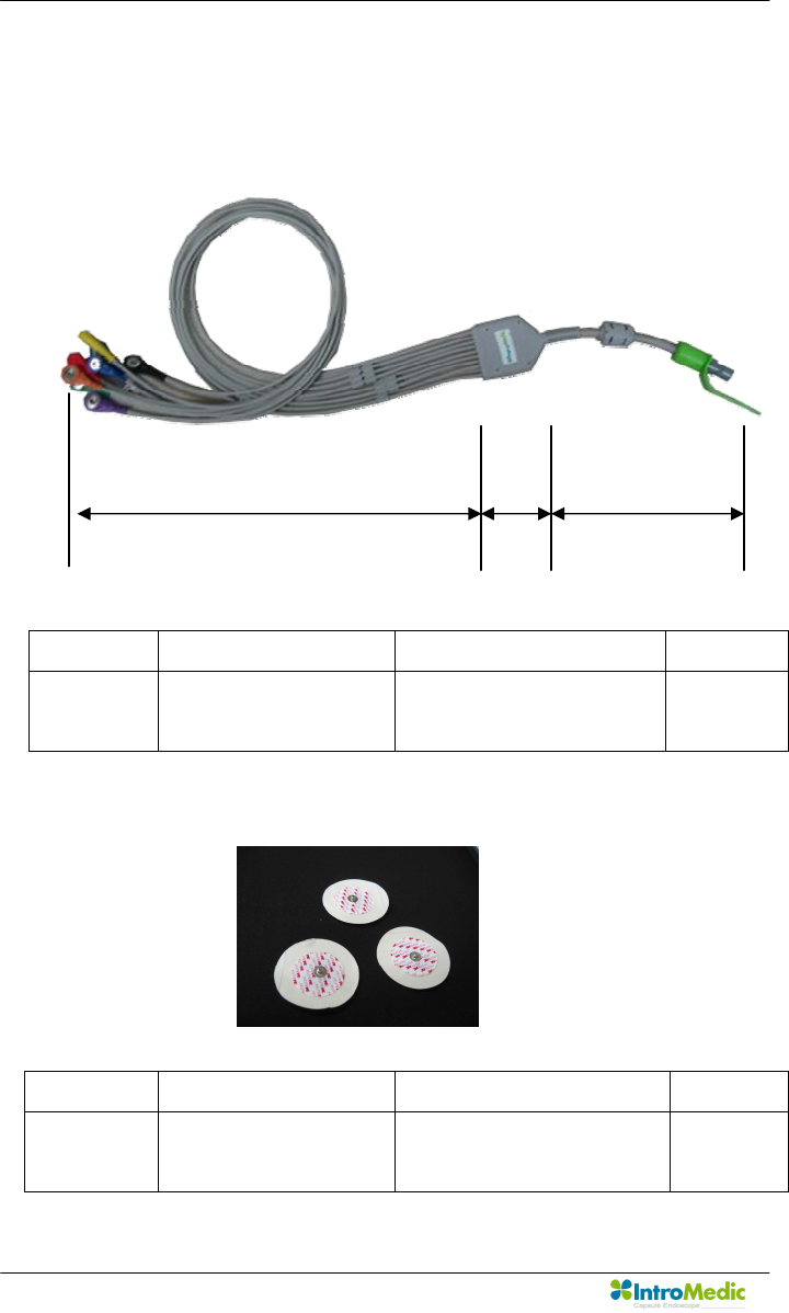
n Data Cable
n Sensor Pads
Part No. Description Size(mm) Weight(g)
MR1000-D Image data receiving
cable
700(L1) x 90(L2) x
110(L3)
155
Part No. Description Size(mm) Weight(g)
MR1000-S Image data receiving
sensors
60 5
L1
L2
L3
Chapter 2 System Overview
Page 35
n USB Cable
n Battery Charger
- Input Specification : 9Vdc, 3A
- Output Specification : 4.2Vdc, 4A
Part No. Description Size(mm) Weight(g)
MR1000-U Image data uploading
cable
1500 50
Part No. Description Size(mm) Weight(g)
MR1000-C Receiver Battery
Charger
135(H) x 105(L) x
150(W)
350
W
L
H
System Overview Chapter 2
Page 36
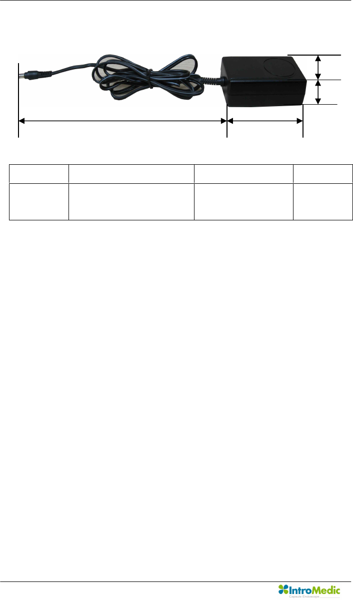
n Adaptor
- Input Specification : 110~220Vac, 50~60/Hz
- Output Specification : 9Vdc, 3A
- Compliance with requirements of IEC601-1
Part No. Description Size(mm) Weight(g)
MR1000-T Receiver Battery
Charging Adaptor
95(W) x 55(L) x
30(H) x 750(D)
240
W
H
L
D

Chapter 2 System Overview
Page 37
2.6 Component List
The components of the MiroCam® System are as follows:
No. Product Name Model Name Q’ty Description Note
1 Capsule
Endoscope
MC1000 1 ea Capsule for imaging
2 Receiver MR1000-R 1 ea Receiver for data storage
3 Battery Pack MR1000-B 2 ea Batteries for receiver
4 Receiver Bag MR1000-G 1 ea Portable receiver bag
5 Data Cable MR1000-D 1 ea Data cable
6 Battery
Charger
MR1000-C 1 ea Battery Charger
7 Adapter MR1000-T 1 ea Adaptor for charging
8 USB Cable MW1000-U 1 ea Communication cable for
workstation
9 Measuring
Tape
MR1000-M 1 ea
10 Sensor Pad MR1000-S 1 pk Signal-receiving pad
11 Software MW1000-SV1.0 1 ea Software for image diagnosis
12 User Manual MM1000 1 ea Instruction for use
13 Service
Manual
MM1100 1 ea Instruction for service
<Table 1> List of Component

System Overview Chapter 2
Page 38

3
Product Installation

Product Installation Chapter 3
Page 40

Chapter 3 Product Installation
Page 41
3. PRODUCT INSTALLATION
Installation and initial operation of the system should be performed by
authorized IntroMedic service personnel. .
The following component list should be rechecked prior to product
installation.
3.1 Component Check List
No. Product Name Model Name Q’ty Description Note
1 Capsule
Endoscope
MC1000 1 ea Capsule for imaging
2 Receiver MR1000-R 1 ea Receiver for data storage
3 Battery Pack MR1000-B 2 ea Batteries for receiver
4 Receiver Bag MR1000-G 1 ea Portable receiver bag
5 Data Cable MR1000-D 1 ea Data cable
6 Battery
Charger
MR1000-C 1 ea Battery Charger
7 Adapter MR1000-T 1 ea Adaptor for charging
8 USB Cable MW1000-U 1 ea Communication cable for
workstation
9 Measuring
Tape
MR1000-M 1 ea
10 Sensor Pad MR1000-S 1 pk Signal-receiving pad
11 Software MW1000-SV1.0 1 ea Software for image diagnosis
12 User Manual MM1000 1 ea Instruction for use
13 Service
Manual
MM1100 1 ea Instruction for service
Product Installation Chapter 3
Page 42
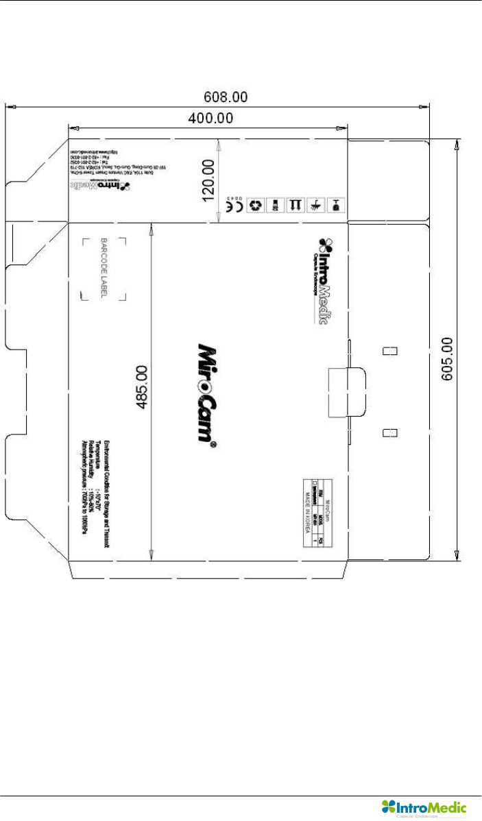
3.2 Packaging Specifications
3.2.1 Capsule Endoscope Receiver set Box : 485 X 120 X 400 mm
Chapter 3 Product Installation
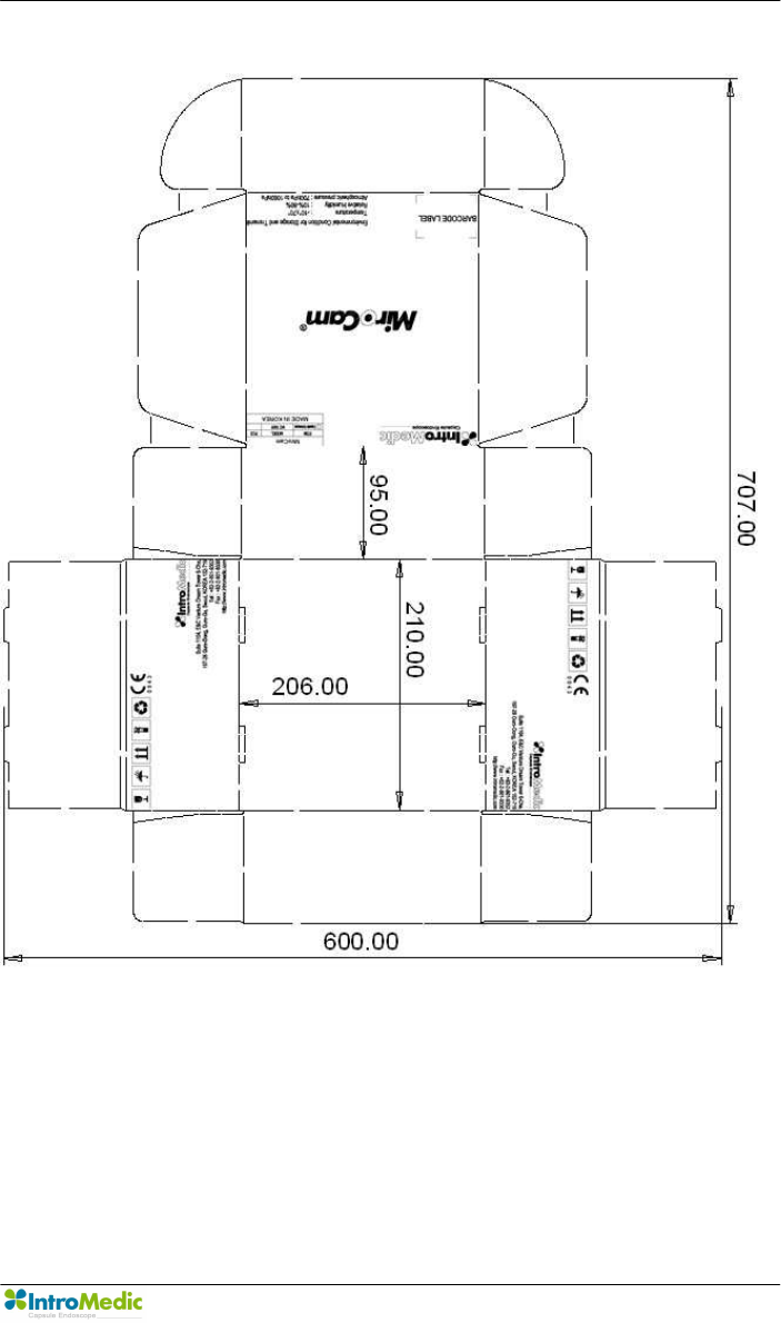
Page 43
3.2.2 Capsule Endoscope Box : 210 X 206 X 95 mm
Product Installation Chapter 3
Page 44
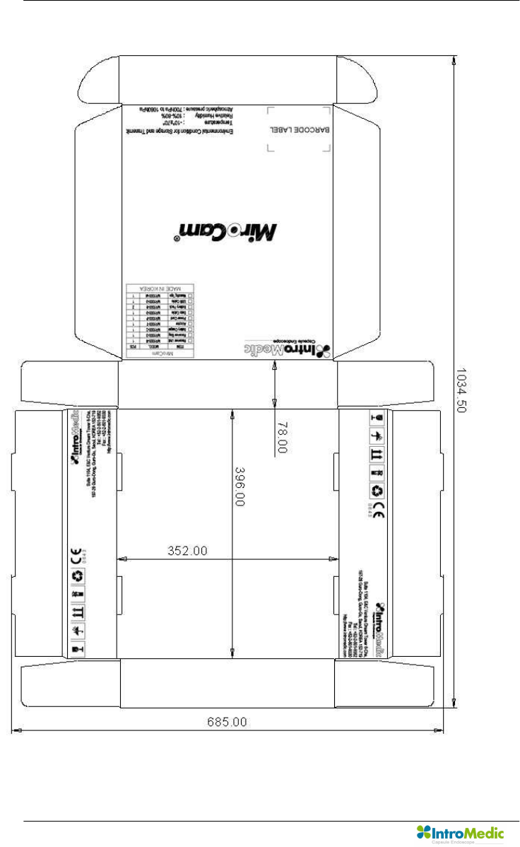
3.2.3 Accessory Box : 352 X 396 X 78 mm
Chapter 3 Product Installation
Page 45
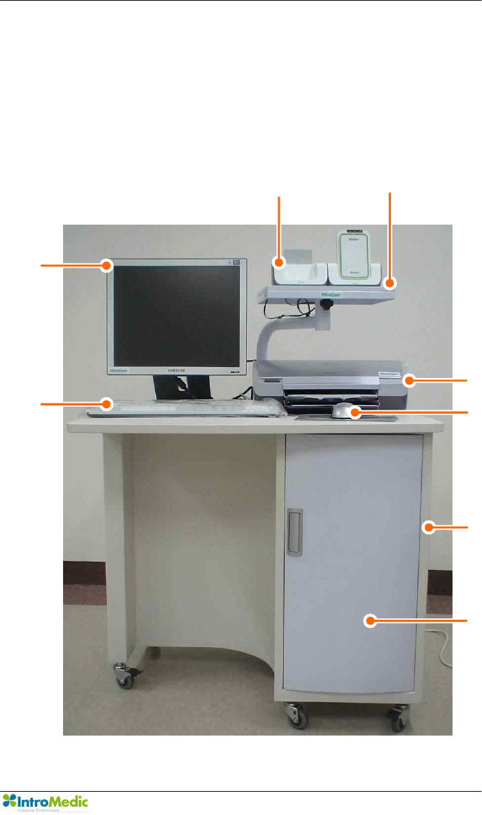
3.3 Installation Diagram
The recommended configuration of the MiroCam® Capsule Endoscope
System is as follows:
Note: configuration may change.
Monitor
Charger
Charger Arm
Printer
Product
Keyboard
Mouse
Table
Product Installation Chapter 3
Page 46
3.4 System Installation & Connection
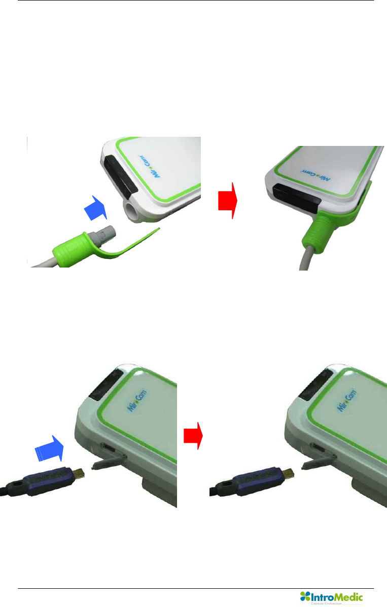
3.4.1 Connect data cable
n Check the data cable’s direction.
n Hold green cover of data cable and insert into the receiver.
3.4.2 Connect USB cable
n Hold small side of USB cable and insert into the receiver.
Chapter 3 Product Installation
Page 47
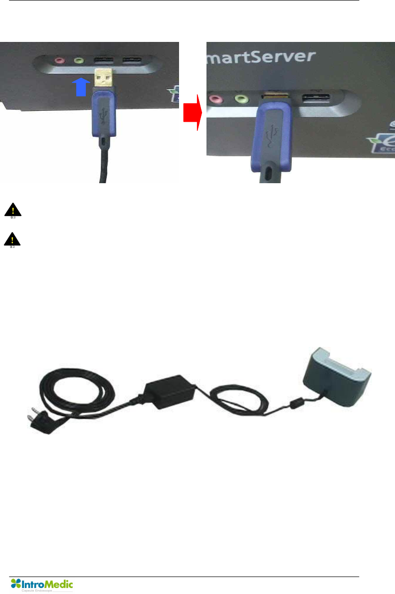
n Hold large side of USB cable and insert into the workstation.
WARNING DO NOT connect the USB cable to the receiver while the
receiver’s sensor pads and data cable are still connected.
WARNING Connect USB cable to receiver only after mounting it on
charger.
3.4.3 Connect battery charger
n Battery charger connection diagram.
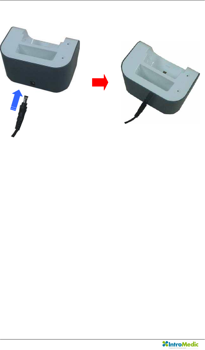
Product Installation Chapter 3
Page 48
n Insert dc-jack of adaptor into battery charger.
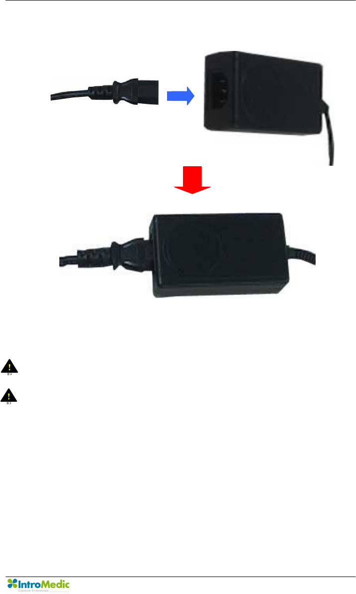
Chapter 3 Product Installation
Page 49
n Insert power-jack of power cord into adaptor.
n Connect power plug of power cord into AC consent.
WARNING Always check the AC Power range before connect power
plug into AC consent.
WARNING DO NOT touch AC power code with wet hand.

Product Installation Chapter 3
Page 50
3.5 MiroView™ Installation
For installation and operation of MiroView™ application software, the
workstation must be prepared. Recommended workstation specifications are
provided to the local IntroMedic Representative, who will install the system
and software.
3.5.1 Preparation(Prior to Installing MiroView Software)
n Setup hard disk drive
- This process should be done by the hardware vendor
- HDD must have three partitions : C, D and E drive
- C drive should have larger space than 150GB for database
- D drive should have larger space than 50GB for MiroView™
- E drive should have larger space than 250GB for patient data.
Chapter 3 Product Installation
Page 51
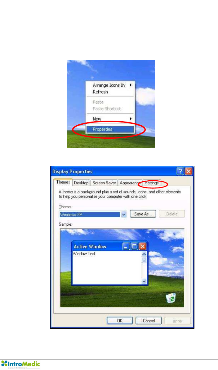
n Setup graphic resolution
- Click mouse right button.
- Click properties in command list.
- In display properties window click settings tab.
Product Installation Chapter 3
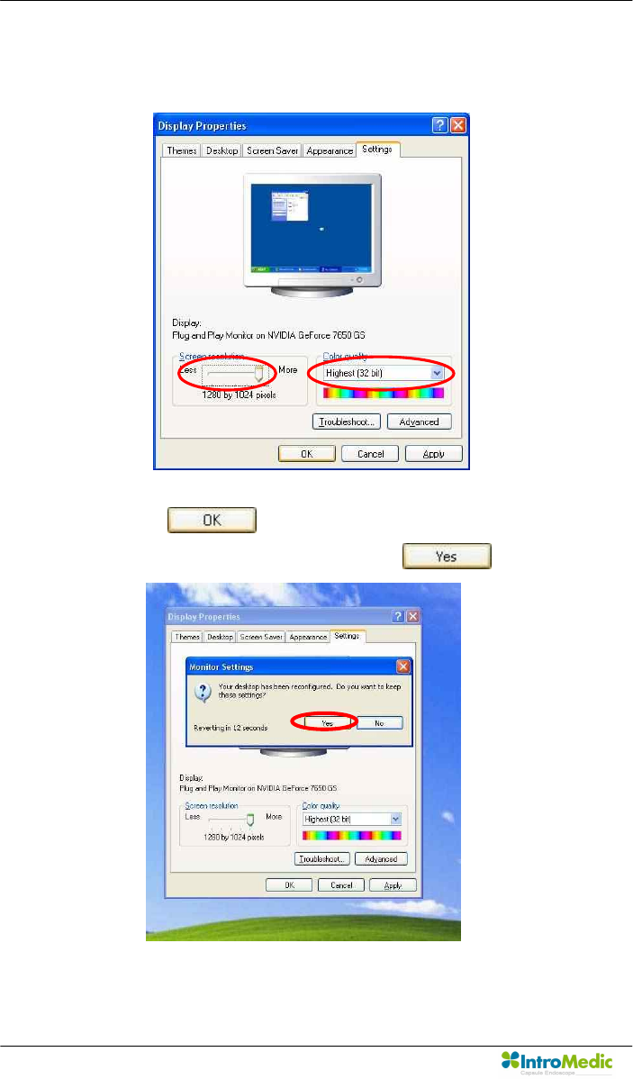
Page 52
- Setting screen resolution by 1280 * 1024 and color quality by
Highest(32 bit).
- Click button.
- Confirm monitor setting by clicking button.
Chapter 3 Product Installation
Page 53
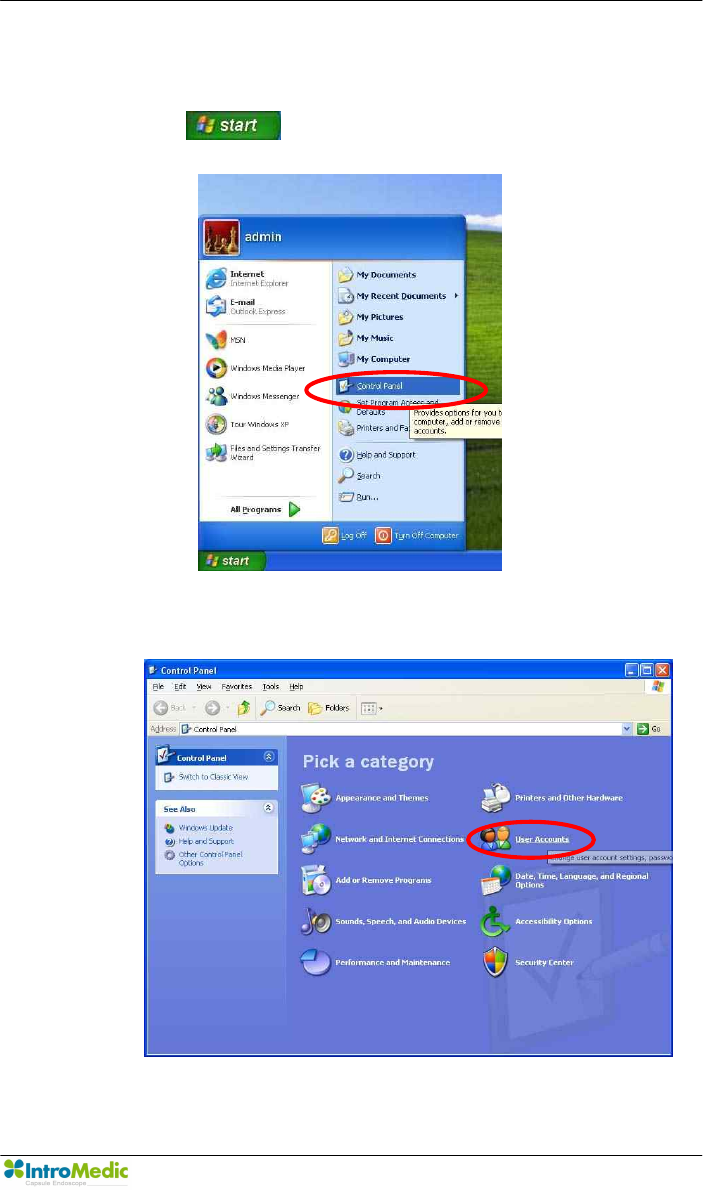
n Setup windows account
- Click button and select ‘Control Panel’.
- Select ‘User Account’.
Product Installation Chapter 3
Page 54
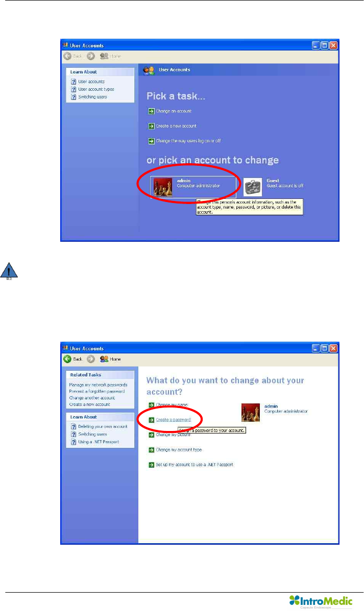
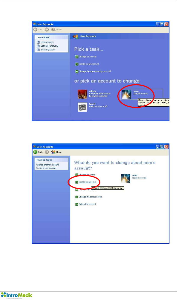
- Select “Admin” account.
NOTE If you can’t see admin account, create admin account by
select “Create a new account”.
- Select ‘Create a password’.
Chapter 3 Product Installation
Page 55
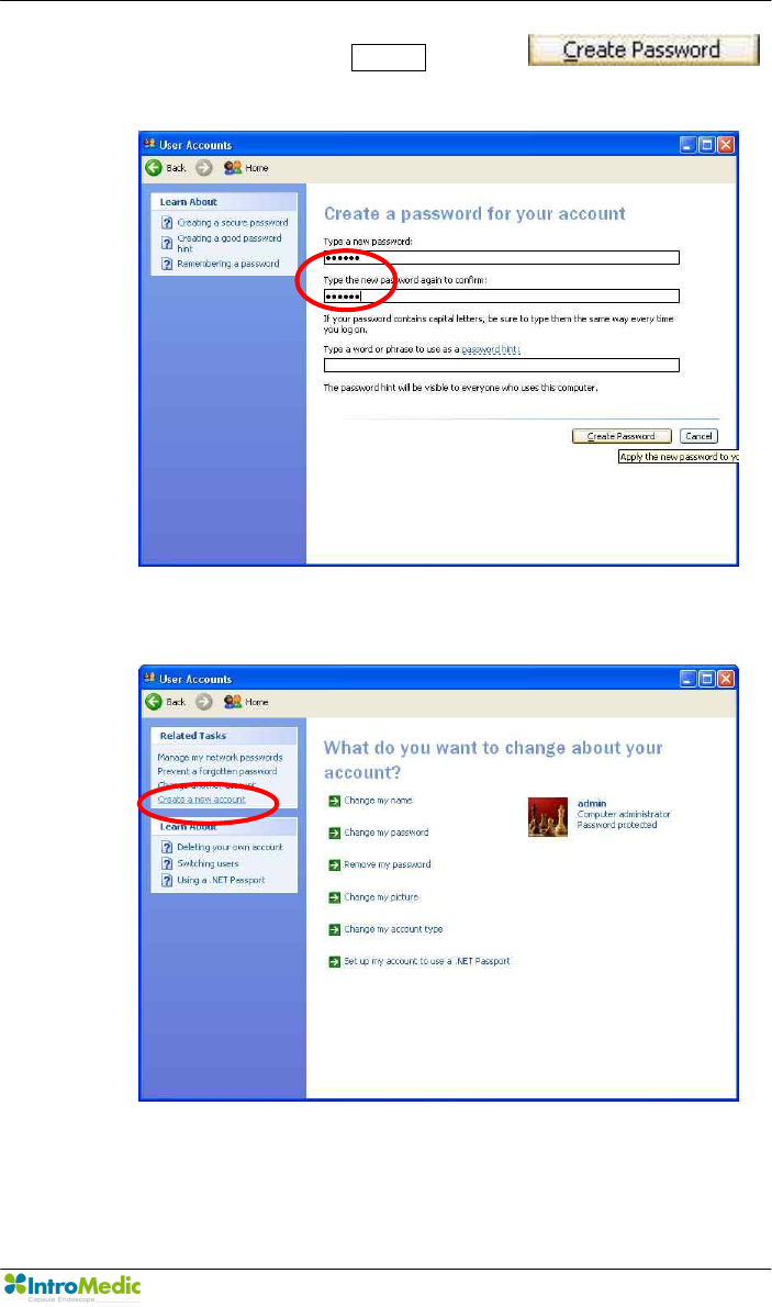
- Enter new password miro06 and click
button
- Select ‘Create a new account’.
Product Installation Chapter 3
Page 56
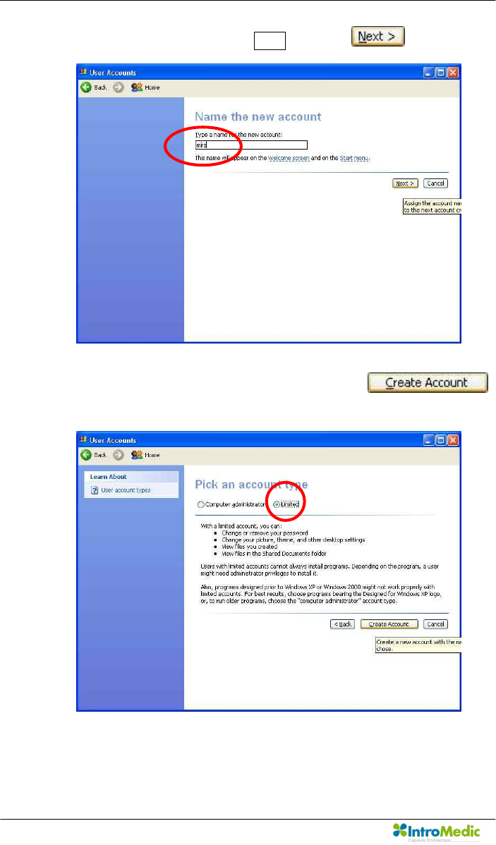
- Enter new account name miro and click button
- Check account type by ‘limited’ and click
button.
Chapter 3 Product Installation
Page 57
- Select “miro” account
- Select ‘Create a password’.

Product Installation Chapter 3
Page 58
- Enter new password miro06 and click
button
- Click button
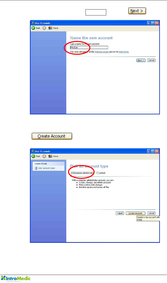
- Select ‘Create a new account’.
Chapter 3 Product Installation
Page 59
- Enter new account name MiroCam and click button
- Check account type by ‘Computer administrator’ and click
button.
Product Installation Chapter 3
Page 60
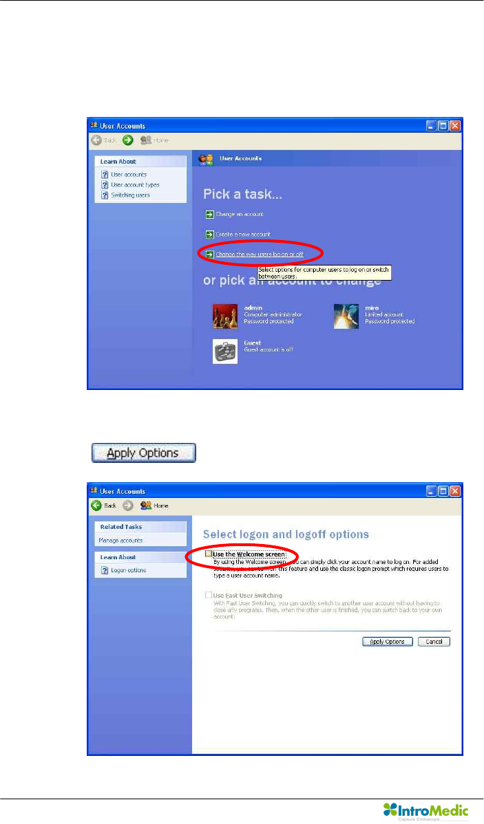
n Autonomous log-on for the user
- Select ‘Change the way users log on or off’
- Uncheck ‘Use the Welcome screen’ and click
button.
Chapter 3 Product Installation
Page 61
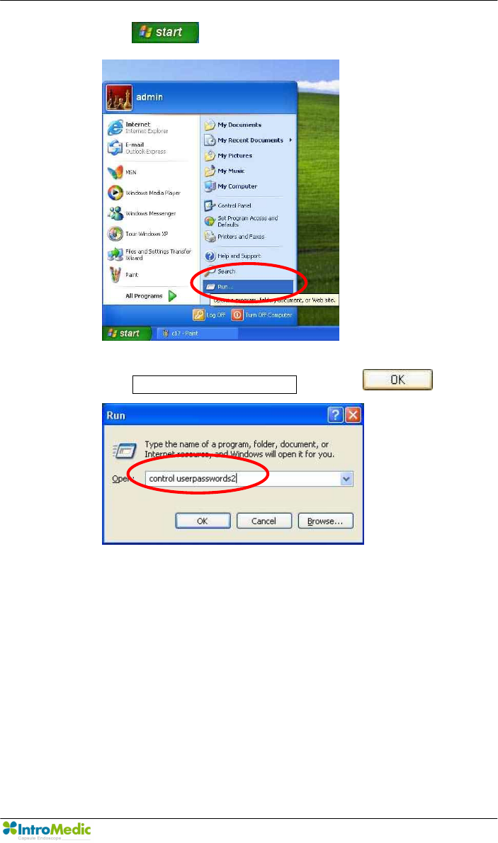
- Click button and select ‘Run’.
- Enter control userpasswords2 and click button
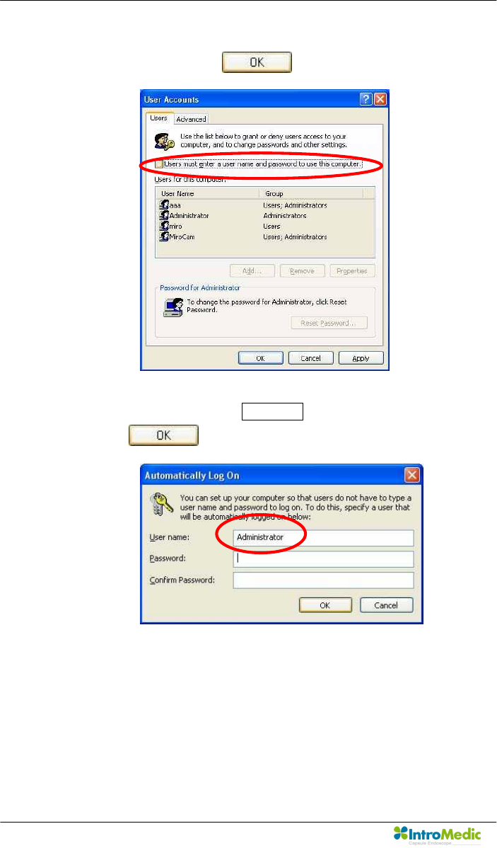
Product Installation Chapter 3
Page 62
- Uncheck ‘User must enter user name and password to use this
computer’ and click button
- Change User name to MiroCam instead of Administrator and
click button.
- Log-off and Log-on with using ‘MiroCam’ account.
Chapter 3 Product Installation
Page 63
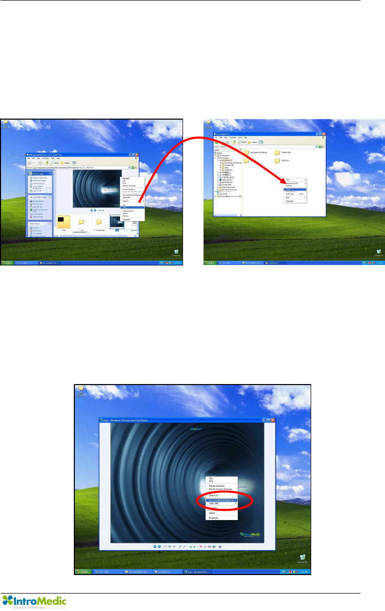
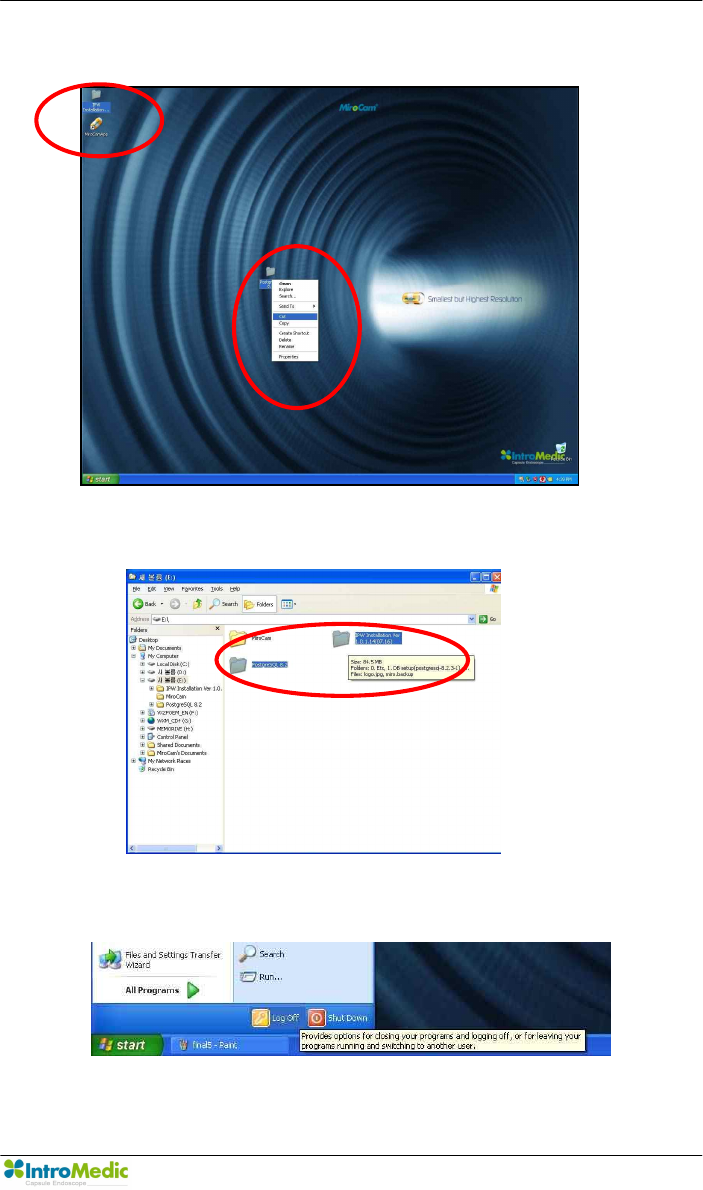
n Setup wallpaper
- Copy ‘IPW Installation Ver 1.0.1.x (2007.x.x)’ from the IPW
installation CD to desktop.
- Copy ‘Logo.jpg’ file to ‘C:\logo.jpg’
<Copy> <Paste>
- Double click ‘logo.jpg’ file to execute Windows Fixture and Fax
Viewer.
- Move the mouse pointer to center of the picture and click the
right button on the mouse and click ‘Set as Desktop
Background’
Product Installation Chapter 3
Page 64
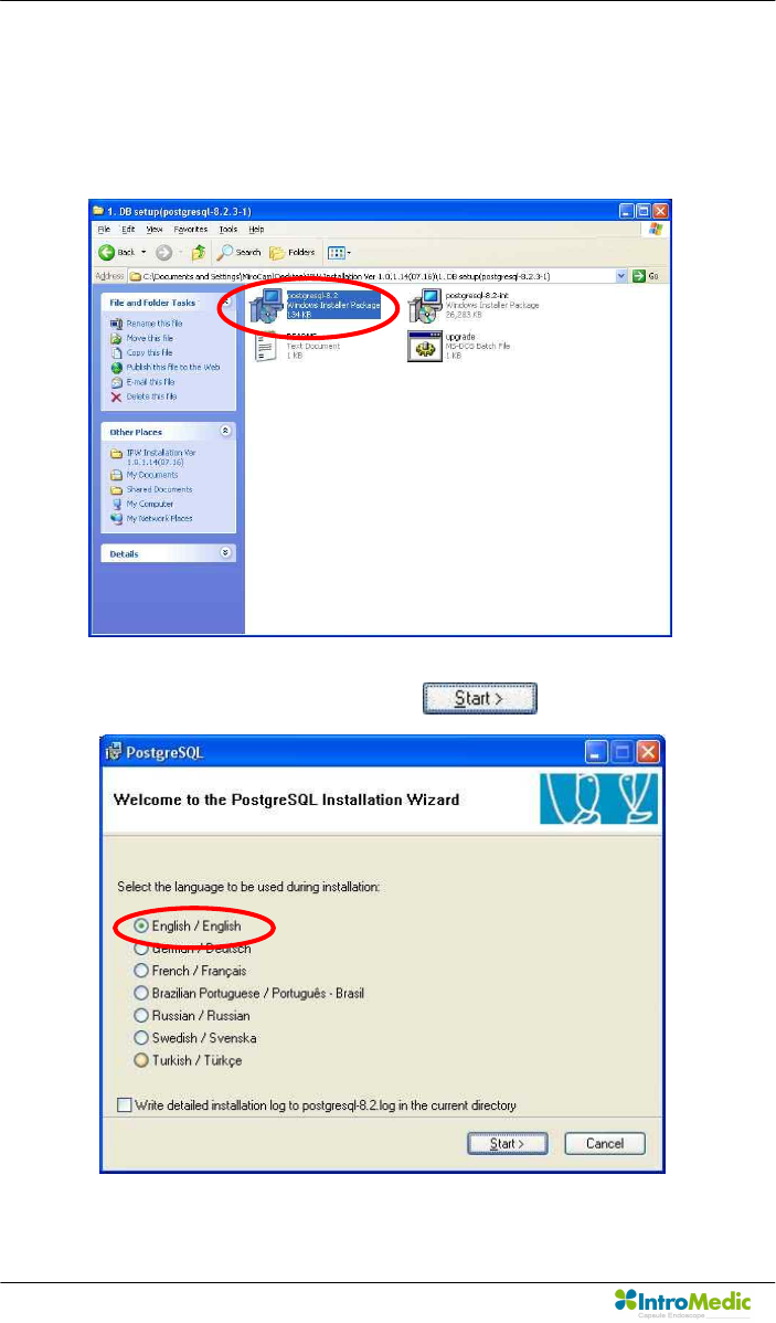
3.5.2 Database setup
n Open ‘1. DB Setup (postgresql-8.2.3-1)’ folder.
n Double click ‘postgresql-8.2.smi’ file to execute.
n Check English/English and click button.
Chapter 3 Product Installation
Page 65
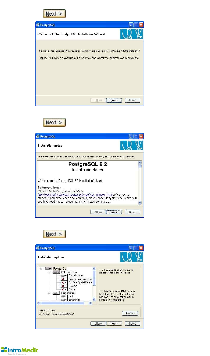
n Click button.
n Click button.
n Click button.
Product Installation Chapter 3
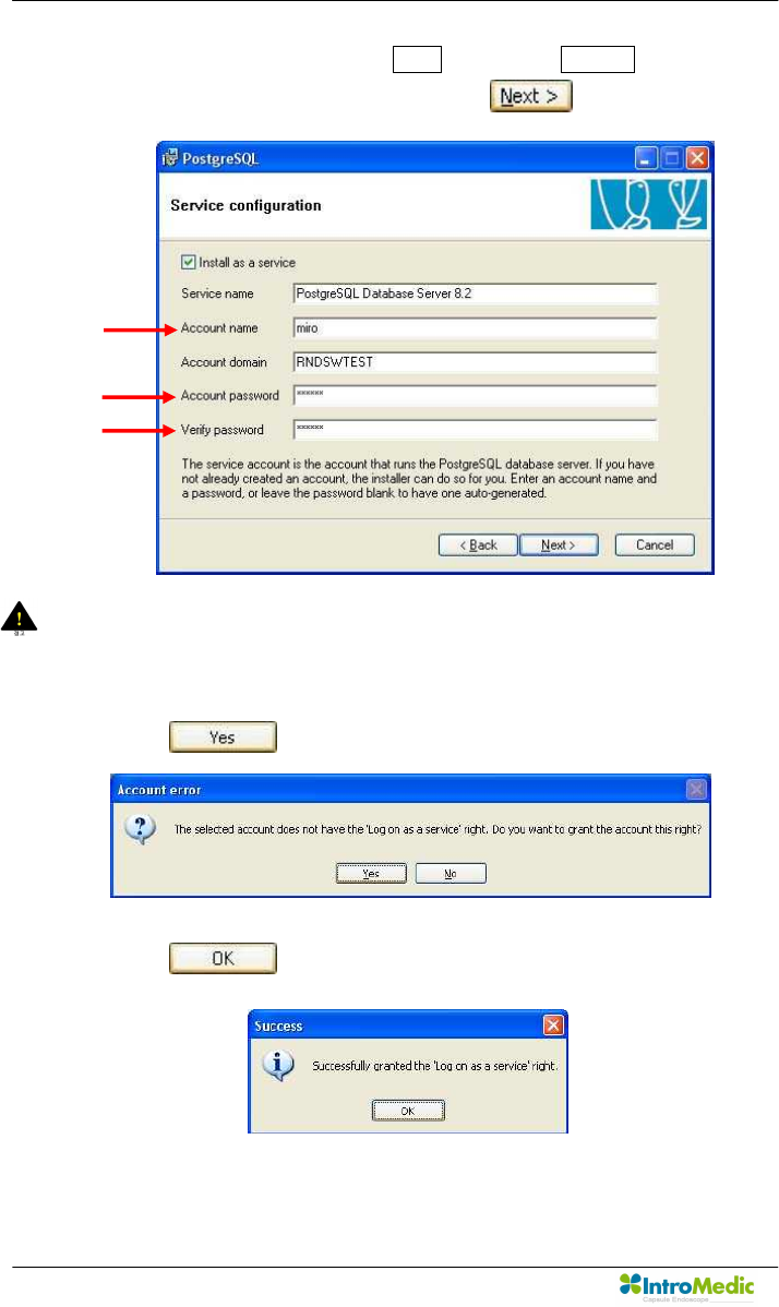
Page 66
n Change ‘Account name’ to miro and enter miro06 for ‘Account
password’ and ‘Verify password’. Click button.
WARNING There is a default value for the ‘Account Domain’. This
should NOT be changed, although it may be different than
detailed in the image above.
n Click button.
n Click button.
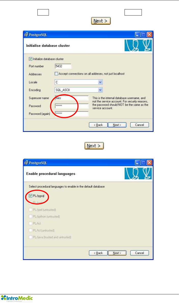
Chapter 3 Product Installation
Page 67
n Enter miro for ‘Superuser name’ and enter miro06 for ‘Password’
and ‘Password (again)’. Click button.
n Check ‘PL/pgsql’ and click button.
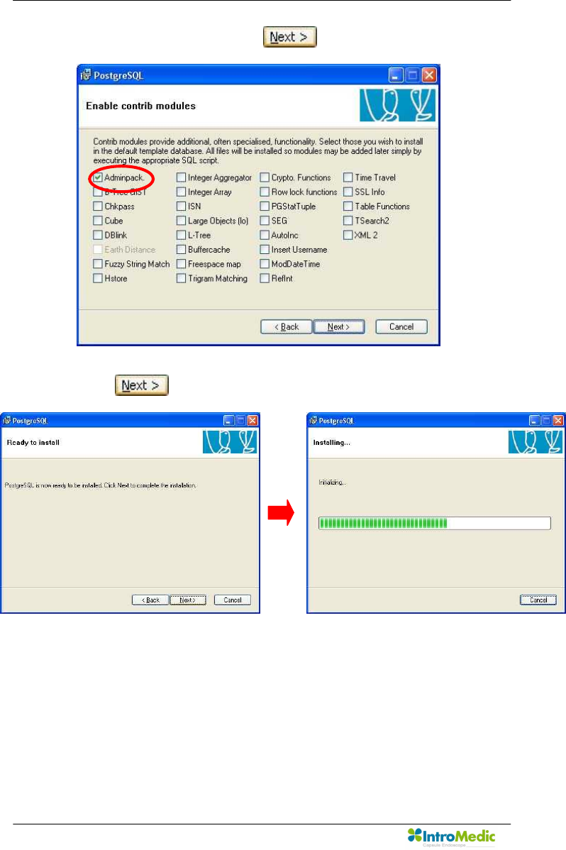
Product Installation Chapter 3
Page 68
n Check ‘Adminpack’ and click button.
n Click button.
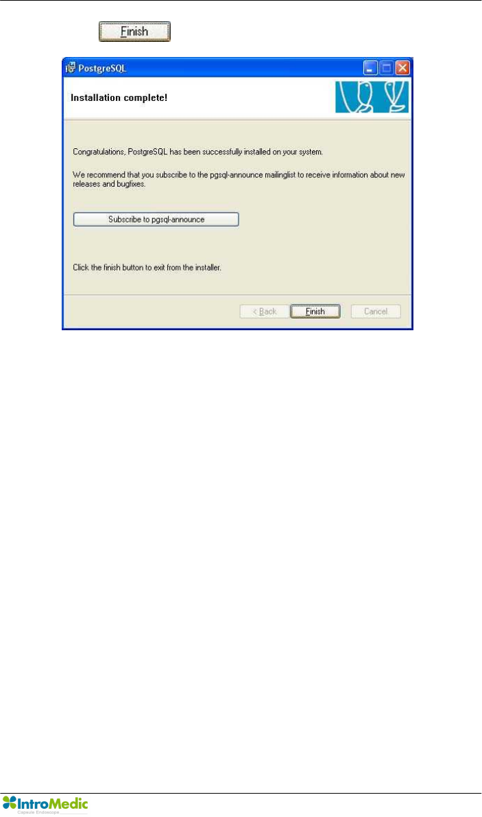
Chapter 3 Product Installation
Page 69
n Click button.
Product Installation Chapter 3
Page 70
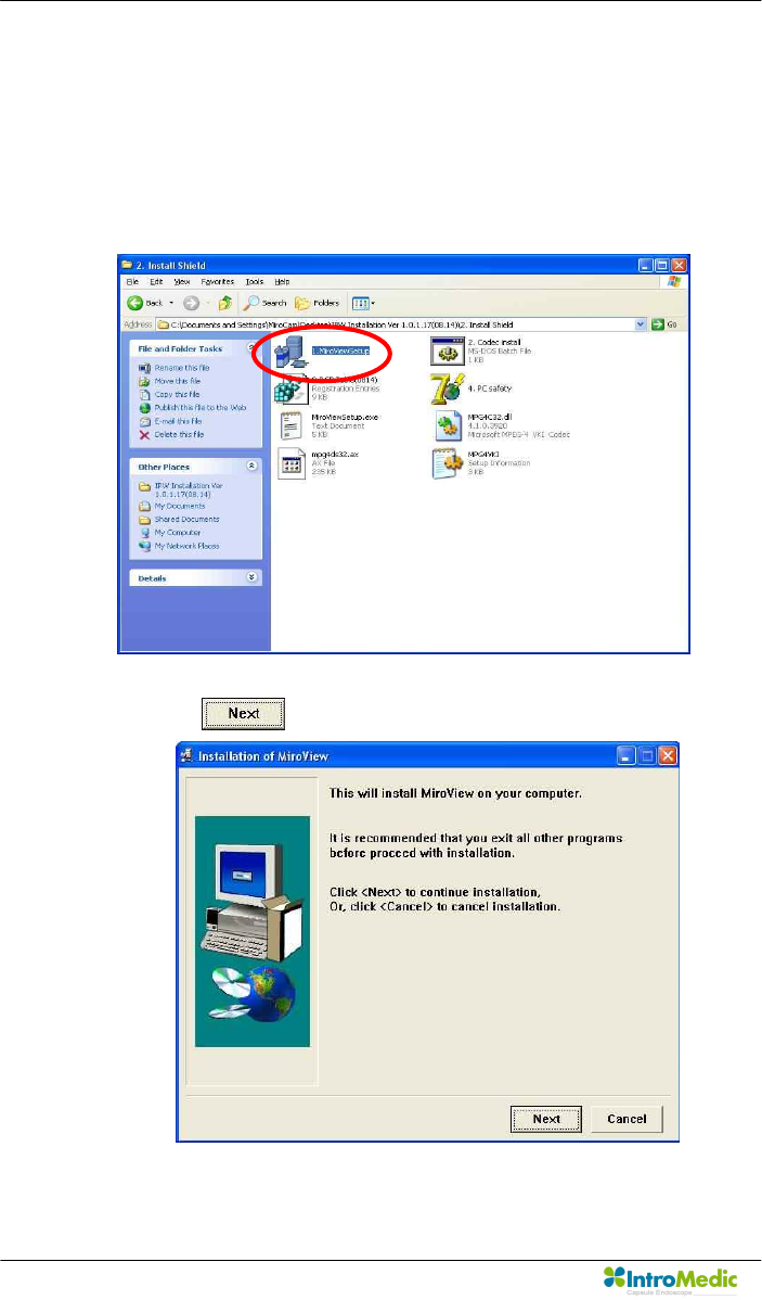
3.5.3 Software installation
n MiroView™ application software installation.
- Open ‘Installshield’ folder and double click ‘1. MiroViewSetup’
- Click button
Chapter 3 Product Installation
Page 71
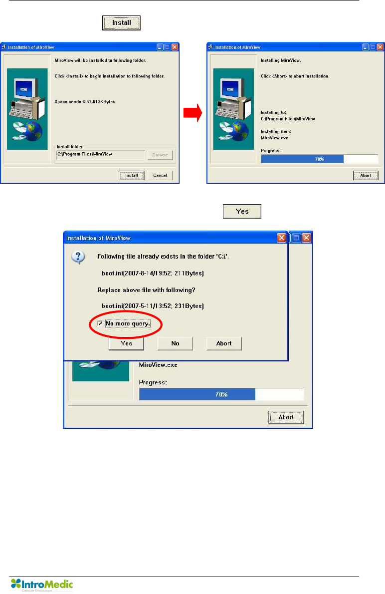
- Click button.
- Check ‘No more query’ and click button.
Product Installation Chapter 3
Page 72
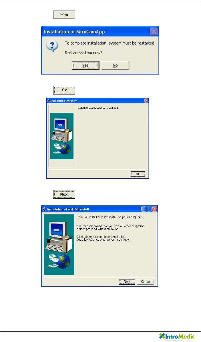
- Click button.
- Click button.
- Click button.
Chapter 3 Product Installation
Page 73
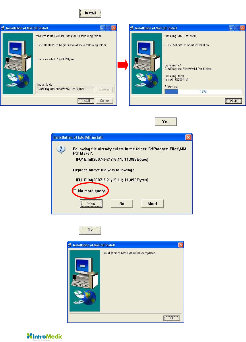
- Click button.
- Uncheck ‘No more query’ and click button,
- Click button.
Product Installation Chapter 3
Page 74
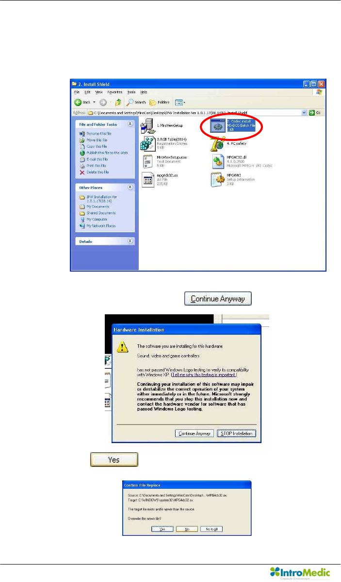
n Codec Installation.
- Open ‘Install shield’ folder and double click ‘2. Codec Install’
- If this window appear, click button
- Click button
Chapter 3 Product Installation
Page 75
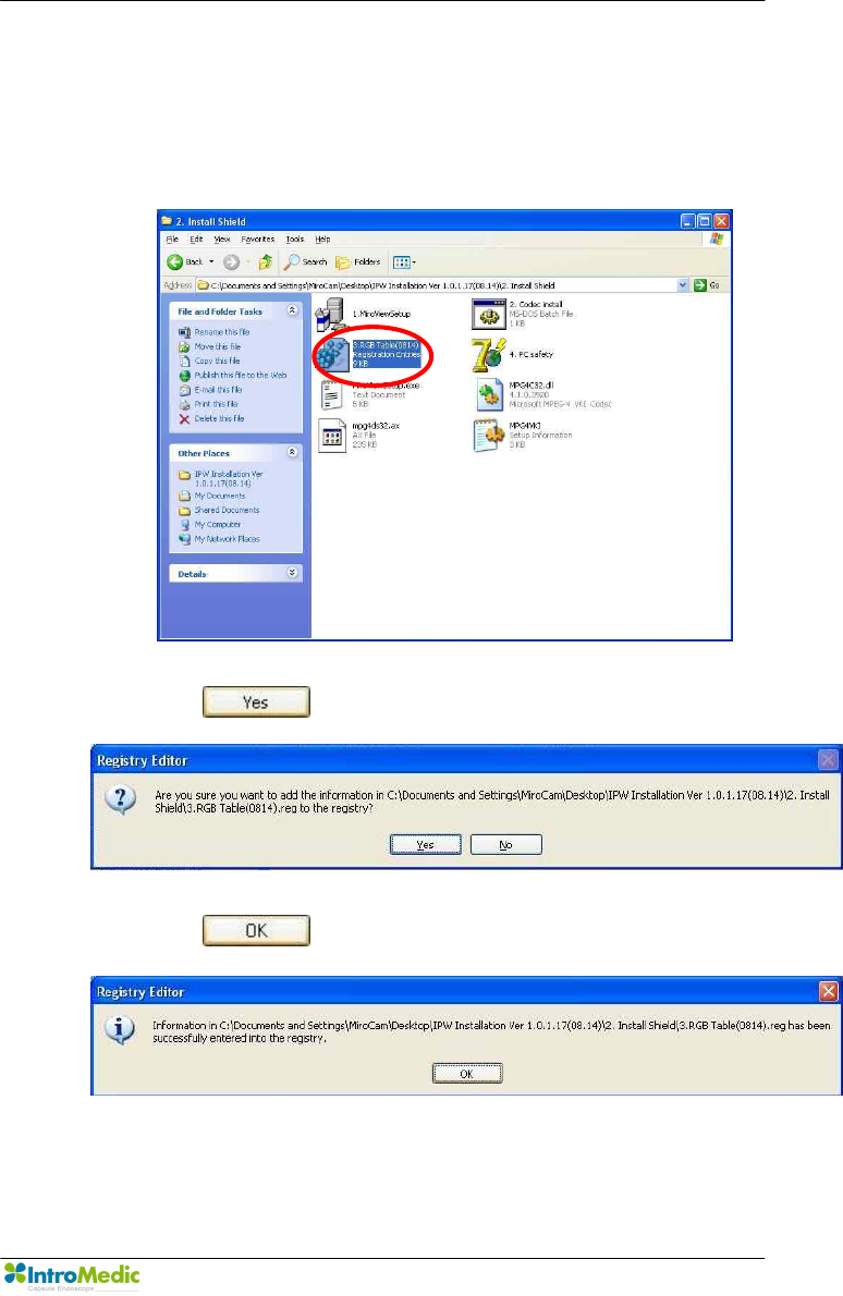
n Registry Installation.
- Open ‘Install shield’ folder and double click ‘3. RGB
Table(0814)’.
- Click button.
- Click button.
Product Installation Chapter 3
Page 76
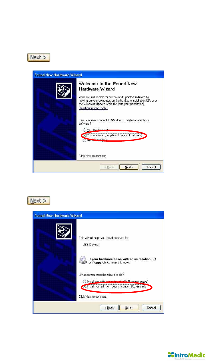
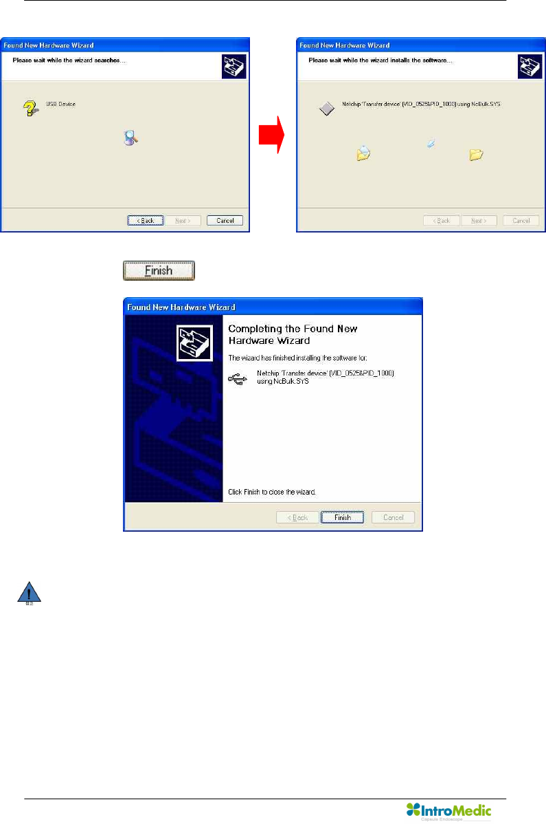
3.5.4 Device driver installation
n Connect a receiver with the PC via USB port
n Check ‘Yes, now and every time I connect a device’ and click
button.
n Check ‘Install from list or specific location (Advanced)’ and click
button.
Chapter 3 Product Installation
Page 77
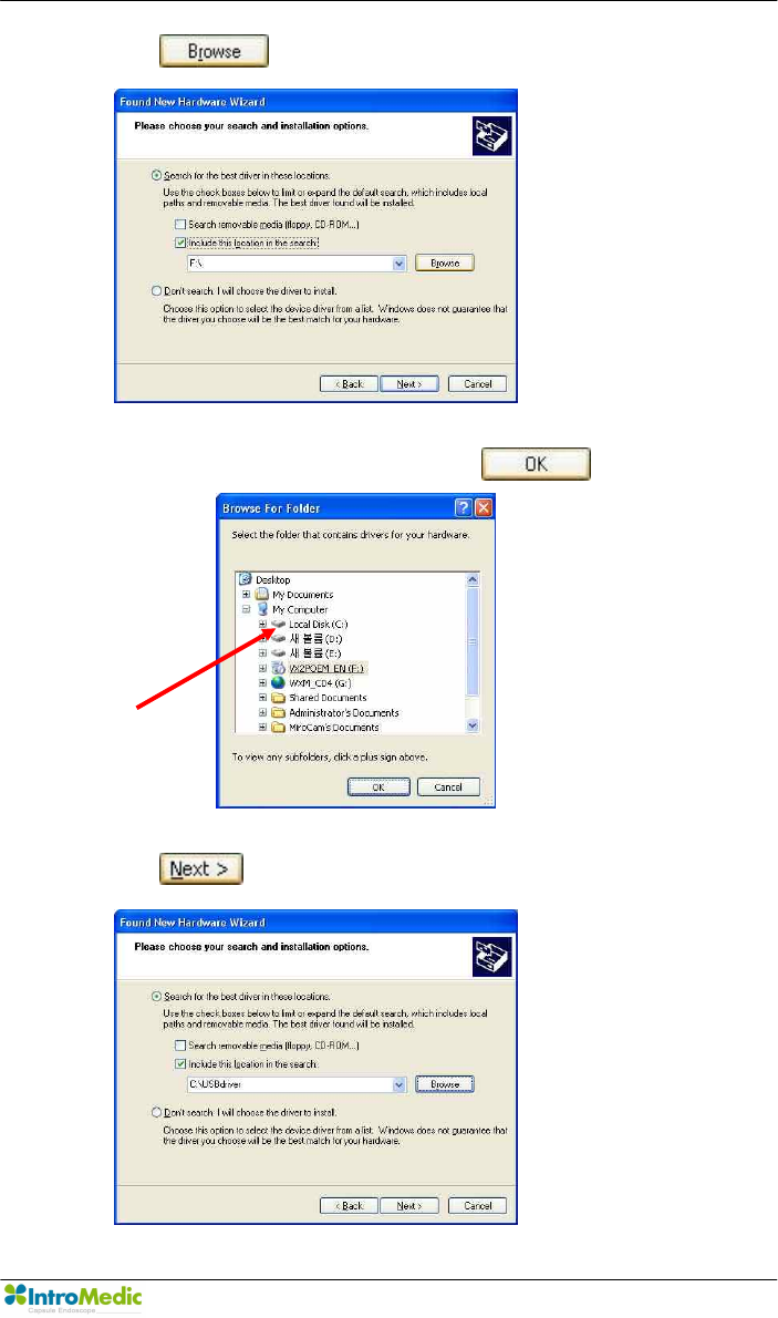
n Click button.
n Select ‘C:\USB Driver’ folder and click button.
n Click button.
Product Installation Chapter 3
Page 78
n Click button.
NOTE USB driver installation process should be undergone for
every USB port to to be used for uploading the receiver
data. If you connect the receiver via a different USB port
from the one with the installed the driver with, then the
driver must be set up again.
Chapter 3 Product Installation
Page 79
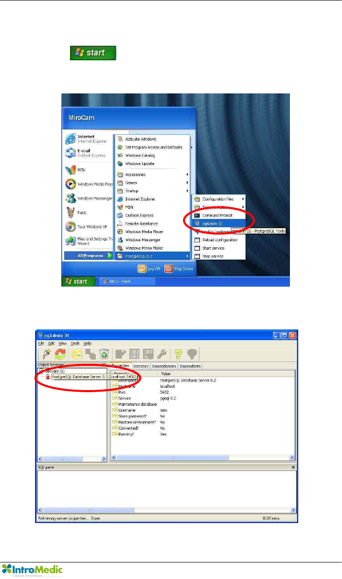
3.5.5 Make the tables on the database
n Click button and select ‘All program à postgreSQL 8.2’.
n Select ‘pgAdmin III’
n Double click ‘PostgreSQL Database Server 8.2 (Localhost : 5432)’
Product Installation Chapter 3
Page 80
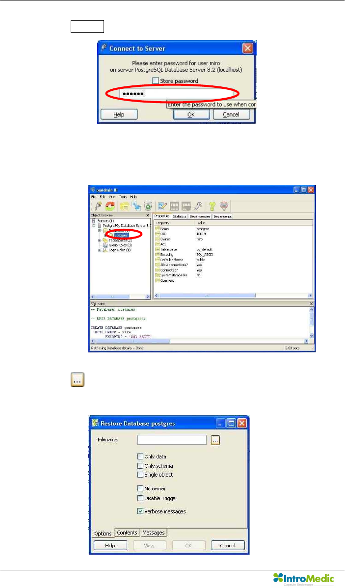
n Enter miro06.
n Select ‘postgres’ and click the right button on the mouse and run
‘Restore’ in the pop-up menu.
n Click button and look for ‘miro.backup’ in the installation folder
on desktop.
Chapter 3 Product Installation
Page 81
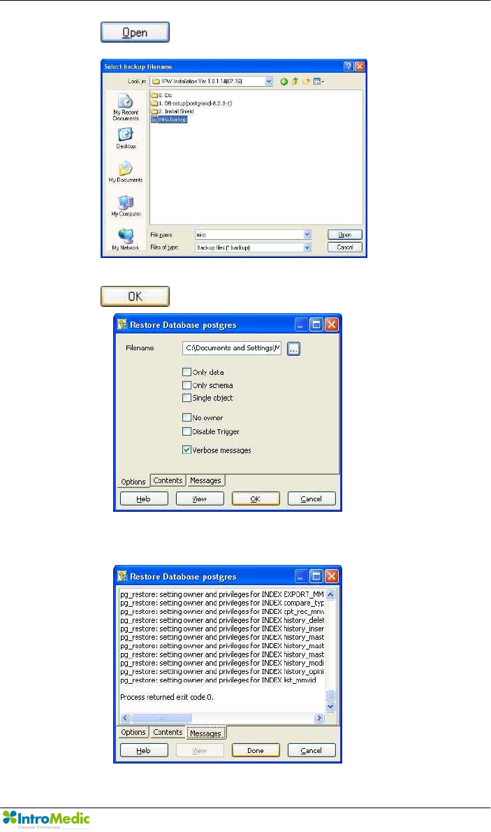
n Click button.
n Click button.
n If you see done button, the restoration is successfully complete.
Click done button.

Product Installation Chapter 3
Page 82
3.5.6 Finalize
n Execute MiroView™ Software by double-clicking icon.
n If the form for registration appears, setting up the MiroView™ is
successfully complete.
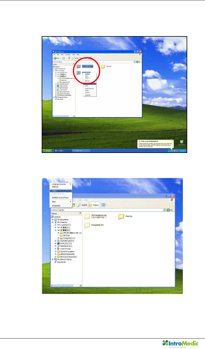
n Move this folder with pushing the left button on the mouse and
dragging to the desktop.
Chapter 3 Product Installation
Page 83
n Cut two folders; ‘IPW Installation…...’ and ‘Postgres……’.
n Paste to the E drive.
n Log off and log on whit ‘admin’ account.
Product Installation Chapter 3
Page 84
n Cut two folders; ‘IPW Installation…...’ and ‘Postgres……’ from E
drive.
n Paste to the desktop.
Chapter 3 Product Installation
Page 85
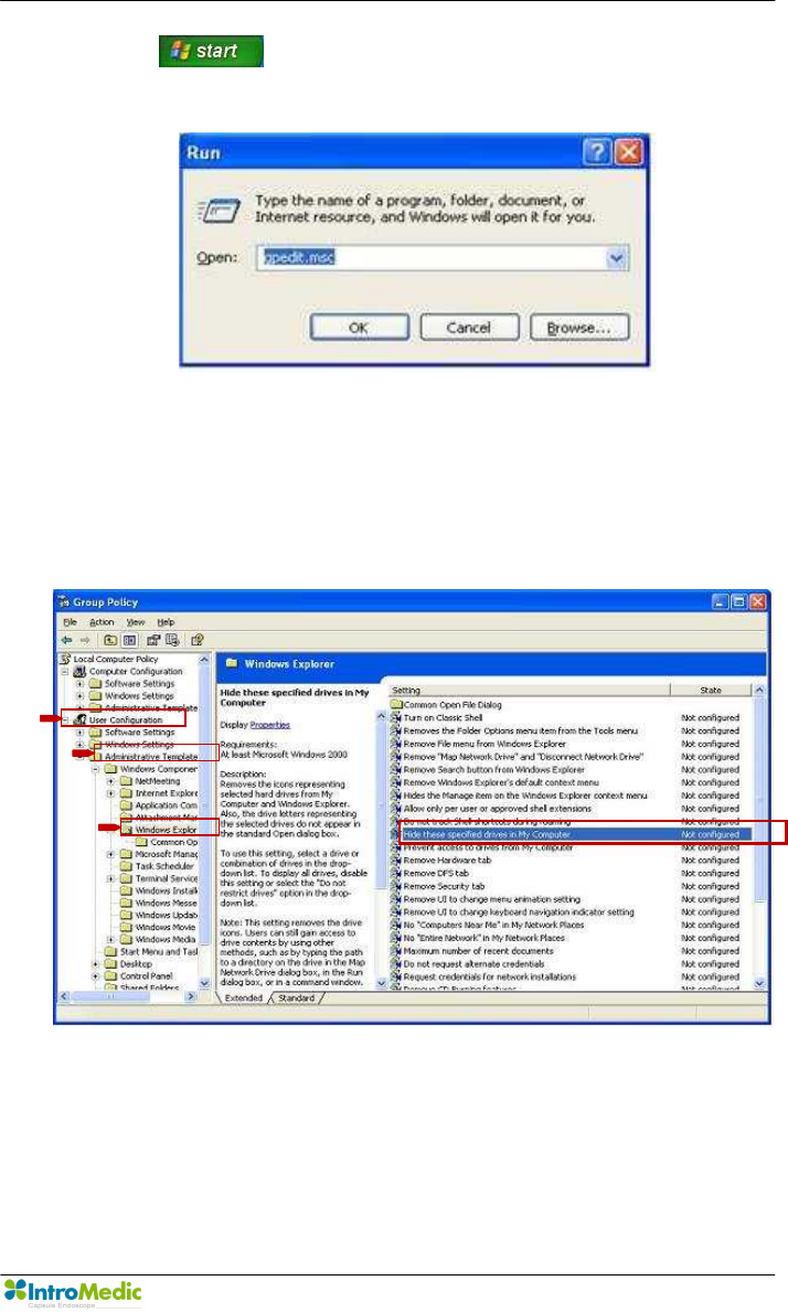
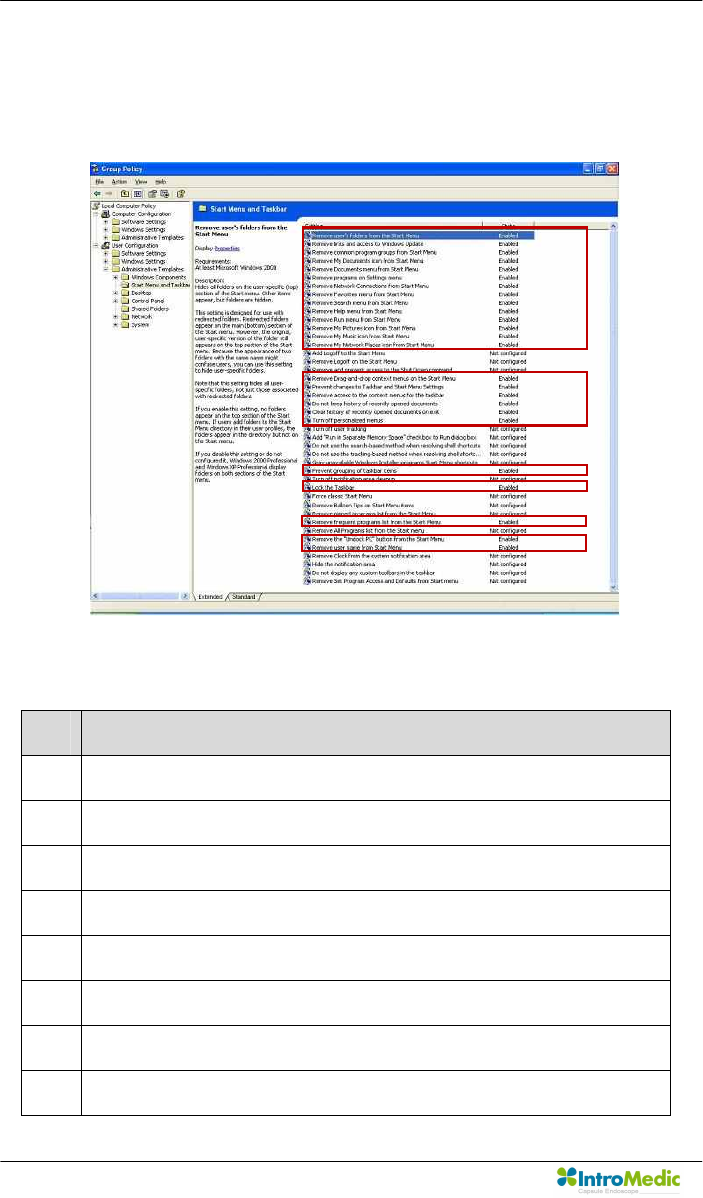
n Click button and select ‘Run’ and type “gpedit.msc” into
the form and Enter.
n Select ‘User Configuration à Administrative Template à
Windows Components à Windows Explorer’ on the left side of the
window and double click ‘Hide these specified drives in My
Computer’.
Product Installation Chapter 3
Page 86
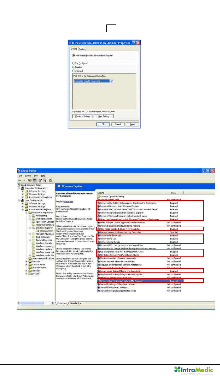
n If a form appears like below, check on ‘Enabled’ and select “Restrict
A, B and C drives only” and OK.
n Double clicked the specified items like below and get them to
“Enabled”.

Chapter 3 Product Installation
Page 87
- Enabled item list
Line Description
2 Remove the folder Options menu item from the Tools manu
3 Remove File menu from the Windows Explorer
4 Remove “Map Network Drive” and “Disconnect Network Drive”
5 Remove search button from Windows Explorer
6 Remove Windows Explorer’s default context menu
7 Hide the Manage item on the Windows Explorer context memu
10 Hide these specified drives in My Computer
12 Remove Hardware tab
13 Remove DFS tab
14 Remove Security tab
17 No “Computer Near Me” in my Network Places
18 No “Entire Network” in My Network Places
23 Do not move deleted files to the Recycled bin
26 Remove Shared Documents from My Computer
Product Installation Chapter 3
Page 88
n Select ‘User Configuration à Administrative Template à Start
Menu and Taskbar on the left side of the window and set items to
“Enabled” like below.
- Enabled item list
Line Description
1 Remove user’s folders from the Start Menu
2 Remove links and access to Windows Update
3 Remove common program groups from Start Menu.
4 Remove My Document icon from Start Menu
5 Remove programs on Setting menu
6 Remove Network Connections from start menu
7 Remove Favorites menu from Start menu
8 Remove Search menu from Start menu

Chapter 3 Product Installation
Page 89
Line Description
9 Remove Help menu from Start menu
10 Remove Run menu from Start menu
11 Remove My Pictures icon from Start menu
12 Remove My Music icon from Start menu
13 Remove My Network Places icon from Start menu
17 Remove Drag-and-drop context menus on the Start menu
18 Prevent changes to taskbar and Start Menu Settings
19 Remove access to the context menus for the taskbar
20 Do not keep history of recently opened documents
21 Clear history of recently opened documents on exit
22 Turn off personalized menus
28 Prevent grouping of taskbar items
30 Lock the Taskbar
34 Remove frequent programs list from the Start menu
36 Remove the “Unlock PC” button from the Start menu
37 Remove user name from Start menu
Product Installation Chapter 3
Page 90
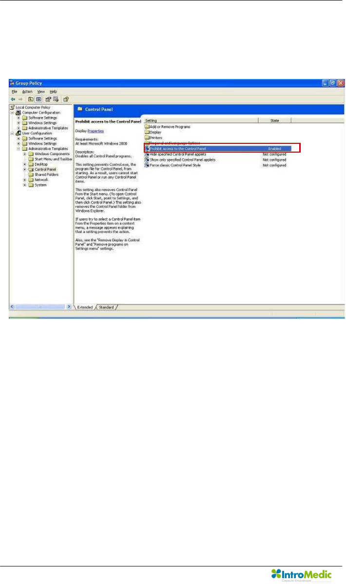
n Select ‘User Configuration à Administrative Template à Control
Panel’ on the left side of the window and set ‘Prohibit access to the
Control Panel’ to “Enabled” like below.
n Installation is finished.

4
Technical Data

Technical Data Chapter 4
Page 92

Chapter 4 Technical Data
Page 93
4. TECHNICAL DATA
4.1 Overview
n Product Name: MiroCam Capsule Endoscope System
n Model Name: MiroCam
n Serial Number: Refer to the label which is attaching in the reverse
side of the product.
n Manufacturer: IntroMedic. Co., Ltd.
n Manufacturer Address
Suite 1104, E&C Venture Dream Tower 6-Cha
197-28 Guro-Dong, Guro-Gu, Seoul, KOREA 152-719
Tel : +82-2-801-9300
Fax : +82-2-801-9330
http://www.intromedic.com
e-mail : help@intromedic.com
4.2 Classification of Equipment
4.2.1 According to the type of protection against electric shock
: Internally Powered Equipment
4.2.2 According to the degree of protection against electric shock
: Type BF Applied Part
4.2.3 According to the degree of protection against ingress of water
: IPX0
4.2.4 According to the method of sterilization or disinfection
: Equipment not usable sterilization & disinfection
4.2.5 According to the degree of safety of application in the presence
of a FLAMMABLE ANAESTHETIC MIXYURE WITH AIR or WITH
OXYGEN OR NITROUS OXIDE
: Equipment not suitable for use in the presence of a

Technical Data Chapter 4
Page 94
FLAMMABLE ANAESTHETIC MIXYURE WITH AIR or WITH
OXYGEN OR NITROUS OXIDE
4.2.6 According to the mode of operation
: Continuous Operation with Short-Time Loading Equipment
4.3 Hardware
4.3.1 Capsule (Model: MC1000-C)
n Size: 10.8 X 24mm
n Weight: 3.25g
n Material: Human Compliance Plastic
n Light: 6 white LED
n View Angle: 150°(In image)
n View Depth: 3 cm
n Enlargement Ratio: 1:8
n Detectable Range: under 0.1mm
n Sampling Ratio: 2.9 fps
n Working time: 11 hours
n Mechanical Safety: Compatible ISO60601-1-1
n Biocompatibility Safety: Compatible ISO10993-4, ISO10993-5,
ISO10993-10, ISO10993-11
n Chemical Safety: Safe in pH=2 ~ pH=8
n Battery Type: Silver Oxide Cell
n Operation Temperature: 20 ~ 40℃
n Storage Temperature: 0 ~ 50℃
n Recommended Maximum Storage Time: 1 Year
4.3.2 Receiver(Model: MR1000-R, MR2000-R)

Chapter 4 Technical Data
Page 95
n Operation System: Firmware
n Recording Time: 12 Hours
n Weight: 350g, include battery
n Operation Voltage: 3.7V, 0.45A
n Battery Type:
l MR1000: Lithium Ion Battery (3.7V, 8.8A)
l MR2000: Lithium Ion Battery (3.7V, 10.4A)
n Battery Weight: 215g
n Operation Temperature: 0 ~ 40℃
n Storage Temperature: 0 ~ 55℃
n Category: Type BF
n Life Time: 4.62 Year
4.3.3 Battery Charger(MR1000-C)
n Input Voltage: 9VDC
n Input Current: 3A
n Output Voltage: 4.2VDC
n Output Current: 4A
n Operation Display: LED Display
n Adaptor Manufacturer: BridgePower Corporation(JEC Korea)
n Adaptor Model: JMW128XA0902F02
4.3.4 Recommended Image Workstation
n Operating System: Windows XP Professional
n CPU: Core 2 Duo E6300(1.86GHz/2M)
n Memory: DDR II 1GByte(667MHz)

Technical Data Chapter 4
Page 96
n Display Adaptor: Geforce 7600GT 256MB
n Hard Disk: SATA II 160GB, SATA II 320GB
n ODD: DVD-RW
n Monitor Resolution: 1280 X 1024
n Monitor Contrast: 700 : 1
n Printer Resolution: 4800 X 1200 dpi
n Printer Paper: A4
4.4 Software
4.4.1 Version
n MiroView Version 1.1.5
4.4.2 Specification
n Monitor Contrast: 700 : 1
n Language: English
n Data Export: JPEG Image, AVI Video Clip, PDF Data Report
n Data Display: Single or Multi Image, Time Bar, Diagnosis Data
n Event Marker: Small Image with Explanation
n Display Ratio: 5 ~ 30 fps
n Display Mode: Single View, Dual View, Quad View
n Running Mode: Normal View, Quick View, Blood View
n Error Ratio: Under 100 image continuously
4.4.3 Feature
n Language: English

Chapter 4 Technical Data
Page 97
n Color status Display
n User Friendly software feature
n Automated detection of GI tract bleeding
n Color of images are virtually natural

Technical Data Chapter 4
Page 98
4.5 Compliance / Approvals
The MiroCam capsule endoscope system and accessories complies with
the Medical Device Directive 93/42/EEC (CE0843).
In addition, the product complies with
IEC 60601-1:1988 +
A1:1991 + A2:1995
(EN 60601-1:1990 +
A1:1992 + A2:1995)
Medical Electrical Equipment, Part 1 :
General requirement for safety
EN 60601-1-1:2001 Medical Electrical Equipment, Part 1 :
General requirement for safety
Collateral Standard : Medical
Electrical System
EN 60601-1-2:2001 Medical Electrical Equipment, Part 1 :
General requirement for safety
Collateral Standard : Electromagnetic
compatibility
EN 60601-1-4:1998 Medical Electrical Equipment, Part 1 :
General requirement for safety
Collateral Standard : Programmable
Electrical Medical System
EN60601-2-18:1996 Medical Electrical Equipment, Part 2 :
Particular requirement for the safety
of endoscope equipment
EN 10993-1:2003 Biological evaluation of medical
devices, Part 1: Evaluation and
Testing Third Edition

Chapter 4 Technical Data
Page 99
4.5.1 FCC Statement
n This device complies with Part 15 of the FCC Rules. Operation is
subject to the following two conditions: (1) this device may not cause
harmful interference, and (2) this device must accept any
interference received, including interference that may cause
undesired operation.
n CAUTION: Changes or modifications not expressly approved by the
party responsible for compliance could void the user's authority to
operate the equipment.
n NOTE: This equipment has been tested and found to comply with
the limit for a Cass B digital device, pursuant to Part 15 of the FCC
Rules. These limits are designed to provide reasonable protection
against harmful interference in a residential installation. This
equipment generates, uses and can radiate radio frequency energy
and, if not installed and used in accordance with the instructions,
may cause harmful interference to radio communications. However,
there is no guarantee that interference will not occur in a particular
installation, which can be determined by turning the equipment off
and on, the user is encouraged to try to correct the interference by
one or more of the following measures:
- Reorient or relocate the receiving antenna.
- Increase the separation between the equipment and receiver.
- Connect the equipment into an outlet on a circuit different from
that to which the receiver is connected.

Technical Data Chapter 4
Page 100

5
Storage & Transportation

Storage & Transportation Chapter 5
Page 102

Chapter 5 Storage & Transportation
Page 103
5. Storage & Transportation
5.1 Safe Storage Conditions
n Environmental condition for storage
- Temperature : -10℃ - +70℃
- Relative humidity : 10% - 80%
- Atmospheric pressure : 700hPa to 1060hPa
n Keep in the place that is not in contact with water
n Keep in the place out of direct light
n Keep away from hazardous materials for the human body.
n Keep away from children.
n Do not store with chemicals.
n For cleaning, only use gauze with water. Other liquid like alcohol
should not be used.
n Use the provided battery charger for charging.
n If product is not used for an extensive period of time, please
separate the battery from the receiver unit.
5.2 Safety Transportion Conditions
- Temperature : -10℃ - +70℃
- Relative humidity : 10% - 80%
- Atmospheric pressure : 700hPa to 1060hPa
- Product MUST be handled with care, and not dropped.

Storage & Transportation Chapter 5
Page 104

6
Troubleshooting

Troubleshooting Chapter 6
Page 106

Chapter 6 Troubleshooting
Page 107
6. TROUBLESHOOTING
6.1 Introduction
This chapter explains how to troubleshoot the MiroCam® capsule
endoscope system if problems arise. Tables are supplied that list possible
difficulties, probable cause, and recommended actions to correct.
6.2 Who should perform repairs
Only qualified service personnel should open the MiroCam® Capsule
Endoscope System housing, remove and replace components, or make
adjustments.
6.3 Obtain replacement parts
IntroMedic Technical Service provides technical assistance information
and replacement parts. To obtain replacement parts, contact IntroMedic
Co., Ltd. or your local representative. Refer to part names and part
numbers listed on Chapter 2.6, Component List.

Troubleshooting Chapter 6
Page 108
6.4 Troubleshooting Guide
Condition Recommended Action
The MiroCam capsule
endoscope system
workstation fails to
power-up when the
I/O power switch is on.
1. Ensure that the MiroCam capsule endoscope
workstation main system is plugged into an
operational AC outlet in accordance with the input
specification rated on the side panel of the
workstation main system.
2. If the condition persists, contact IntroMedic Co.,
Ltd. or local representative.
The MiroCam capsule
endoscope system
receiver unit fails to
power-up when the
I/O power switch is on.
1. Recharge battery of receiver unit.
2. Replace battery of receiver unit.
3. If the condition persists, contact IntroMedic Co.,
Ltd or local representative.
Capsule is not
blinking when taken
out of the case.
1. DO NOT use the capsule. Use an alternate
capsule.
2. Contact IntroMedic Co., Ltd. for replacement of
capsule.
INI LED on receiver
unit is yellow, and
does not turn green
when held
appropriately by
patient.
1. Initialize receiver unit via MiroView™ software.
2. If the condition persists, contact IntroMedic Co.,
Ltd.
BAT LED, on receiver
unit is yellow.
1. Recharge battery of receiver unit.
2. Replace battery of receiver unit.
3. If the condition persists, contact IntroMedic Co.,
Ltd.

Chapter 6 Troubleshooting
Page 109
If you see following message when you use MiroView™ software, check
possible cause and action before contacting IntroMedic.
Error Message Possible cause Action
1 The selected drive
does not support
CD/DVD burning.
The CD/DVD drive
does not support
CD/DVD burning.
Exchange the
CD/DVD drive for
DVD multi or DVD
writable drive.
2 The selected drive
does not support
CD/DVD burning.
User selected wrong
drive.
Select the DVD
writable drive and try
again.
3 BACKUP or EXPORT
is not yet complete.
Wait for process to
finish and try again.
The user executed
BACKUP or EXPORT
function while the
burning process is
operating.
Wait until the process
has stopped and try
again.
4 The selected capture
cannot be added.
MiroView™ software
installation problem.
Contact to IntroMedic.
5 The selected
landmark cannot be
added.
MiroView™ software
installation problem.
Contact to IntroMedic.
6 Failed to save. MiroView™ software
installation problem.
Contact to IntroMedic.

Troubleshooting Chapter 6
Page 110
7 An error arose while
trying to export.
Please try again.
Improper export
destination selected.
Check the drive to
export.
Check if the drive has
sufficient space.
8 An error arose while
trying to export.
Please try again.
MiroView™ software
installation problem.
Contact IntroMedic.
9 There is no data to
export.
There is no data to
export.
If you did not capture
any image, then this is
not an error. If
persists, contact
IntroMedic.
10 Failed to make a
video file because
Microsoft MPEG4-V2
codec does not exist.
MiroView™ software
Installation problem
Contact IntroMedic
11 Not enough memory. The system resources
are not sufficient to
support MiroView™
Reboot.
12 The file buffer size is
over the limit.
The system resources
are not sufficient to
support MiroView™.
Reboot.

Chapter 6 Troubleshooting
Page 111
13 Failed to create the
file.
The disk space is not
enough.
Delete data (patient
files) from the List
Mode.
14 Not enough storage
space.
The disk space is not
enough.
Delete data (patient
files) from the List
Mode..
15 Failed to find the file. Synchronization error
between files and list
Contact IntroMedic
16 The file type does not
match.
File version error. Contact IntroMedic
17 Database error Failed to access the
DB server.
Reboot.
18 The printer driver is
not installed.
A printer driver (MM
PDF Maker) is not
installed.
Contact IntroMedic
19 The PDF converting
module is not
installed.
Cannot create the
report PDF file
because PDF
converting module is
not installed.
Contact IntroMedic
20 Receiver is
disconnected while
uploading
Cannot continue to
upload because
receiver has become
disconnected.
Check the connection
between the receiver
and the PC.
21 Cannot upload
because receiver is
not connected.
Improper connection
between the receiver
and the PC
Check the connection
between the receiver
and the PC

Troubleshooting Chapter 6
Page 112
22 Cannot upload
because receiver is
not connected.
The receiver is turned
off.
Turn on the receiver
and try again.
23 Fill out all the required
fields.
There are the fields
which you did not
enter the contents
into.
Make sure all require
fields are filled.
24 Failed to upload data
from receiver.
Connection error
between the receiver
and the PC
Check the connection
between the receiver
and the PC
25 Failed to complete
restoration.
MiroView™ software
installation problem.
Contact to IntroMedic
26 Failed to complete
restoration due to
some missing files.
Backup error Back up the data and
restore again
27 Please insert disk
number ##.
The user inserted
wrong disk while
restoring the data
Insert disk with
number ##.
28 Wrong disk. Please
insert a disk of the
same original file.
The user inserted
wrong disk while
restoring the data
Insert the disk of the
same original file.
29 The backup disk info
is incorrect.
Backup error Back up the data and
restore again
Warnning If the problem arises again, contact to IntroMedic Service
center.

7
Packing for shipment

Packing for shipment Chapter 7
Page 114
Chapter 7 Packing for shipment
Page 115
7. PACKING FOR SHIPMENT
To ship the MiroCam® Capsule Endoscope System for any reason,
follow the instructions in this chapter.
7.1 General Introduction
Pack the MiroCam capsule endoscope system carefully. Failure to
follow the instructions in this chapter may result in loss or damage
not covered by the IntroMedic Co., Ltd. warranty. If the original
shipping box is not available, use another suitable box. Return the
product with a detailed, written description of the problem.
7.2 Repacking in Original Packing Box
If available, use the original packing box and packing materials as
illustrated figures in below.
Packing for shipment Chapter 7
Page 116
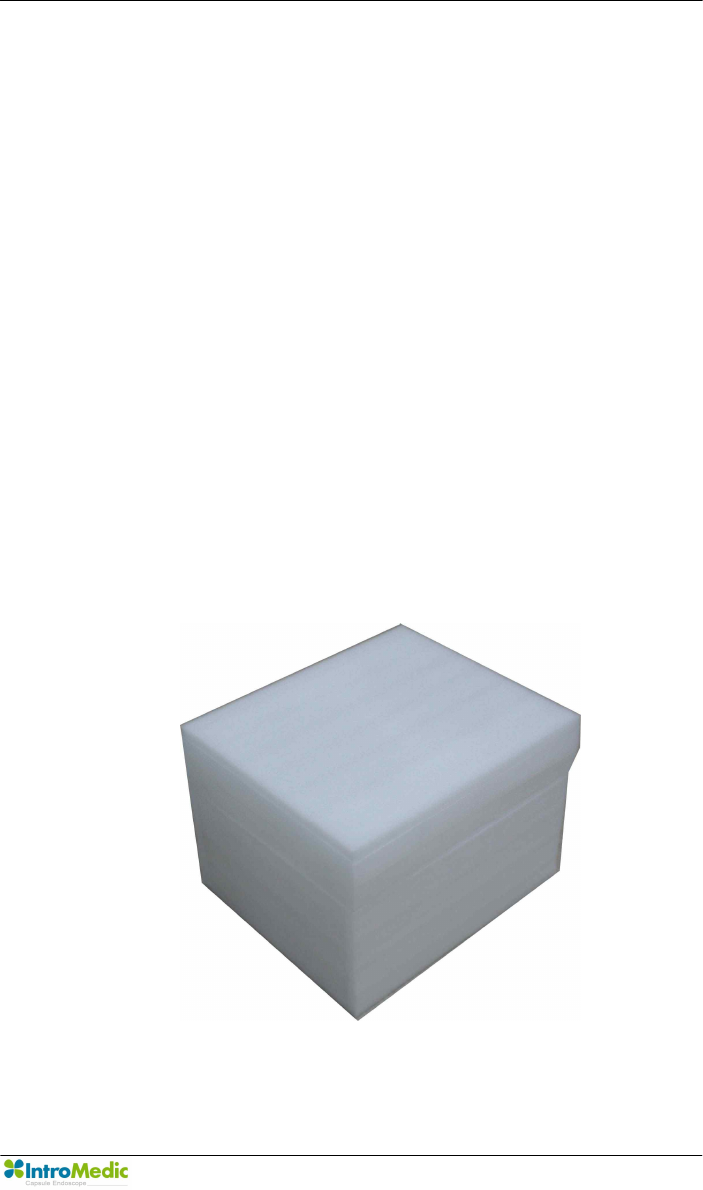
n Repacking MiroCam® capsule
- Insert capsule storage case into capsule box.
- Close capsule box.
Chapter 7 Packing for shipment
Page 117
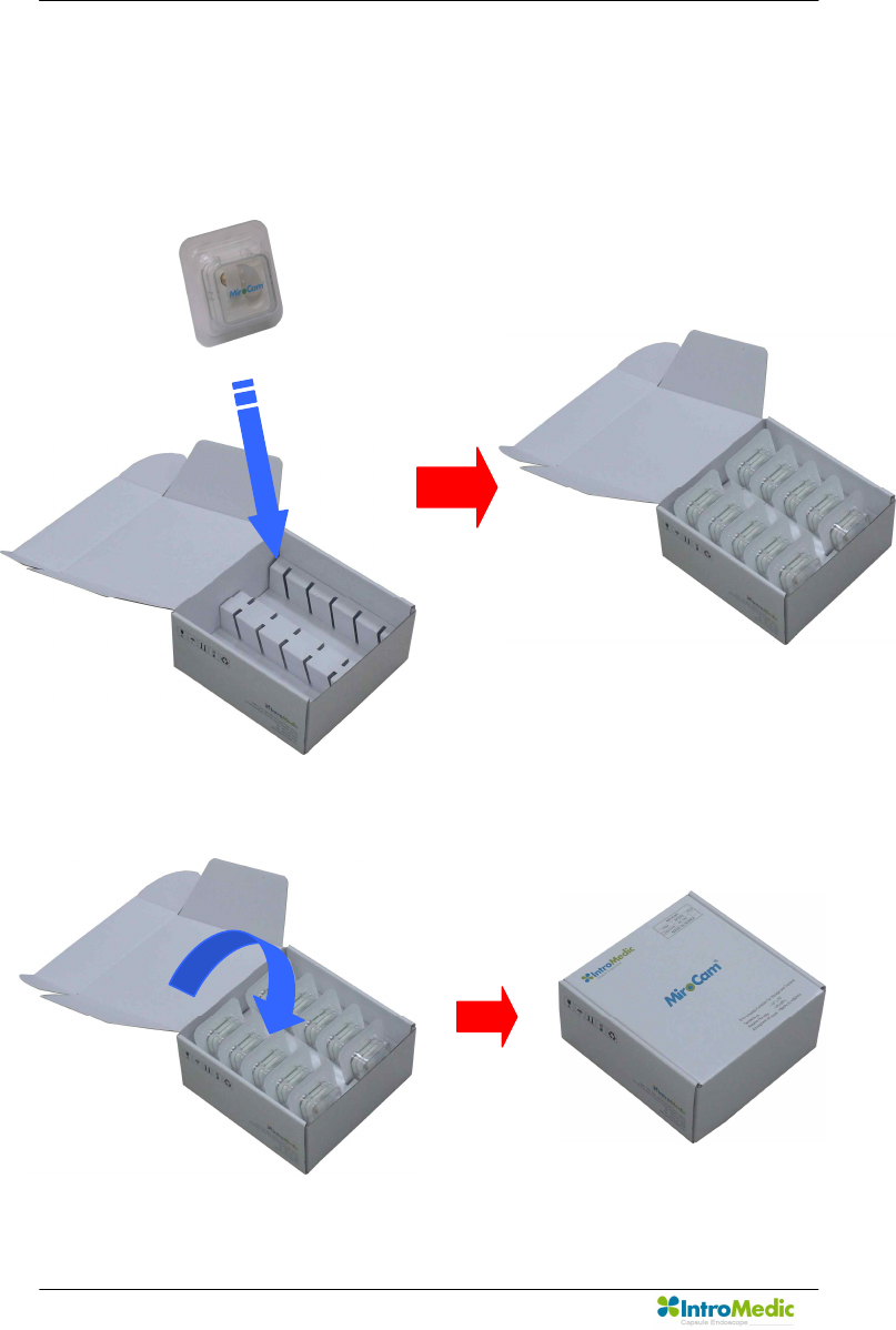
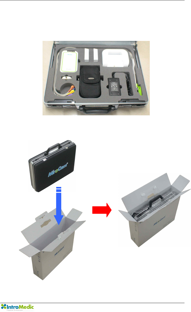
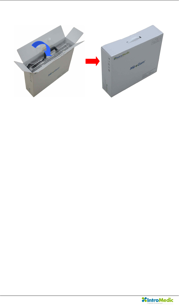
n Repacking MiroCam® receiver unit
- Insert receiver unit into system carry case.
- Insert system carry case into receiver unit box.
Packing for shipment Chapter 7
Page 118
- Close receiver unit box.
Chapter 7 Packing for shipment
Page 119
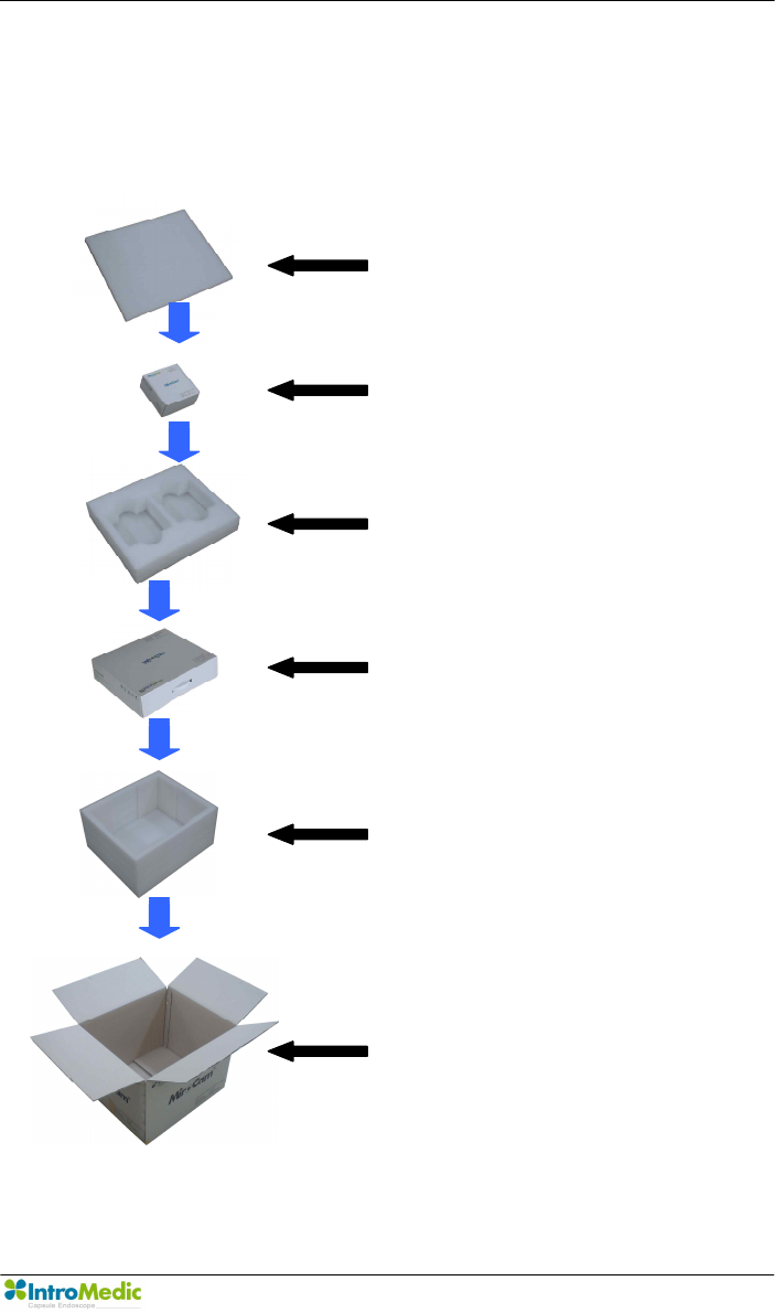
n Repacking MiroCam® capsule endoscope system.
- System repacking diagram.
Upper Case shield
Capsule box
Middle case shield
Receiver unit box
Lower case shield
System box
Packing for shipment Chapter 7
Page 120
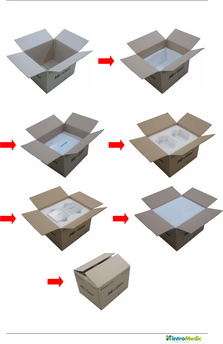
- System repacking procedure.

Chapter 7 Packing for shipment
Page 121
7.3 Repacking in Different Packing Box
If the original packing box is not available:
n Place the MiroCam capsule endoscope system in a plastic
bag.
n Locate a corrugated cardboard shipping box with at least 200
pounds per square inch (psi) bursting strength.
n Fill the bottom of the box with at least 2 inches of packing
material.
n Place the bagged unit on the layer of packing material and fill
the box completely with packing material.
n Seal the packaging box with packing tape.
n Label packing box with shipping address, return address, and
the written description.

Packing for shipment Chapter 7
Page 122

8
EMC Information

EMC Information Chapter 8
Page 124

Chapter 8 EMC Information
Page 125
8. EMC INFORMATION
8.1 Guidance and manufacturer’s declaration -
electromagnetic emissions
The EUT is intended for use in the electromagnetic environment specified below.
The customer or the user of the EUT should assure that it is used in such an
environment.
Immunity test Compliance Electromagnetic environment -
guidance
RF Emissions
CISPR 11 Group 1
The EUT uses RF energy only for its
internal function. Therefore, its RF
emissions are very low and are not likely
to cause any interference in nearby
electronic equipment
RF Emissions
CISPR 11 Class B
The EUT is suitable for use in ail
establishments, including domestic
establishments and those directly
connected to the public low-voltage
power supply network that supplies
buildings used for domestic purposes
Harmonic emissions
IEC 61000-3-2 Class A
Voltage fluctuations/
Flicker emissions
IEC 61000-3-3
Complies

EMC Information Chapter 8
Page 126
8.2 Guidance and manufacturer’s declaration -
electromagnetic immunity
The EUT is intended for use in the electromagnetic environment specified below.
The customer or the user of the EUT should assure that it is used in such an environment.
Immunity test IEC 60601
Test level
Compliance
level
Electromagnetic environment -
guidance
Electrostatic
discharge (ESD)
IEC 61000-4-2
±6kV Contact
±8kV air
±6kV Contact
±8kV air
Floors should be wood, concrete or
ceramic tile. If floors are covered
with synthetic material, the relative
humidity should be at least 30%.
Electrical fast
transient/burst
IEC 61000-4-4
±2kV for power
supply lines
± 1kV for
input/output lines
±2kV for power
supply lines
± 1kV for
input/output
lines
Mains power quality should be that
of a typical commercial or hospital
environment.
Surge
IEC 61000-4-5
±1kV differential
mode
±2kV common
mode
±1kV differential
mode
±2kV common
mode
Mains power quality should be that
of a typical commercial or hospital
environment.
Voltage dips,
short
interruptions and
voltage
variations
on power supply
input lines
IEC 61000-4-11
<5% Uт
(>95% dip in Uт)
for 0.5cycle
40% Uт
(60% dip in Uт )
for 5 cycle
70% Uт
(30% dip in Uт)
for 25 cycle
<5% Uт
(<95% dip in Uт )
for 5 s
<5% Uт
(>95% dip in
Uт)
for 0.5cycle
40% Uт
(60% dip in Uт )
for 5 cycle
70% Uт
(30% dip in Uт)
for 25 cycle
<5% Uт
(<95% dip in
Uт )
for 5 s
Mains power quality should be that
of a typical commercial or hospital
environment. If the user of the EUT
image intensifier requires
continued
operation during power mains
interruptions,
it is recommended that the
EUT image intensifier be powered
from an uninterruptible power
supply or a battery.
Power frequency
(50/60Hz)
magnetic field
IEC 61000-4-8
3 A/m 3 A/m Power frequency magnetic fields
should be at levels characteristic of
a typical location in a typical
commercial or hospital
environment.
NOTE Uт is the a.c. mains voltage prior to application of the test level.
Guidance and manufacturer’s declaration - electromagnetic immunity
Chapter 8 EMC Information
Page 127
8.3 Guidance and manufacturer’s declaration -
electromagnetic immunity
The EUT is intended for use in the electromagnetic environment specified
below.
The customer or the user of the EUT should assure that it is used in such
an environment.
Immunity test IEC 60601 test
level
Compliance
Level Electromagnetic environment - guidance
Conducted RF
IEC 61000-4-6
Radiated RF
IEC 61000-4-3
3 Vrms
150 kHz to
80MHz
3 V/m
80 MHz to
2.5GHz
3 Vrms
150 kHz to
80MHz
3 V/m
80MHz to
2.5GHz
Portable and mobile RF communications
equipment should be used no closer to any
part of the EUT, including cables, than the
recommended separation distance
calculated from the equation applicable to
the frequency of the transmitter.
Recommended separation distance
where P is the maximum output power
rating of the transmitter in watts (W)
according to the transmitter manufacturer
and d is the recommended separation
distance in meters (m).
Field strengths from fixed RF transmitters,
as deter-mined by an electromagnetic site
80MHz to 800MHz
800MHz to 2.5GHz
EMC Information Chapter 8
Page 128
survey, a should be less than the compliance
level in each
frequency range. b
Interference may occur in the vicinity of
equipment marked with the following
symbol :
NOTE 1 ) At 80MHz and 800MHz, the higher frequency range applies.
NOTE 2) These guidelines may not apply in all situations. Electromagnetic propagation is affected
by absorption and reflection from structures, objects and people.
a Field strengths from fixed transmitters, such as base stations for radio (cellular/cordless)
telephones and land mobile radios, amateur radio, AM and FM radio broadcast and TV broadcast
cannot be predicted theoretically with accuracy. To assess the electromagnetic environment due
to fixed RF transmitters, an electromagnetic site survey should be considered. If the measured
field strength in the location in which the EUT is used exceeds the applicable RF compliance level
above, the EUT should be observed to verify normal operation. If abnormal performance is
observed, additional measures may be necessary, such as re-orienting or relocating the EUT.
b Over the frequency range 150kHz to 80MHz, field strengths should be less than [V1] V/m.

Chapter 8 EMC Information
Page 129
8.4 Recommended separation distances between portable
and mobile RF communications equipment and the EUT
Intended for use in an electromagnetic environment in which radiated RF
disturbances are controlled. The customer or the user of the EUT can help
prevent electromagnetic interference by maintaining a minimum distance
between portable and mobile RF communications equipment (transmitters)
and the EUT as recommended below, according to the maximum output
power of the communications equipment.
Separation distance according to frequency of transmitter[m]
150kHz to 80MHz
80MHz to
800MHz
800MHz to
2.5GHz
Rated
maximum
output power
of transmitter
[W]
V1=3Vrms E1=3V/m E1=3V/m
0.01 0.116 0.1166 0.2333
0.1 0.368 0.3687 0.7378
1 1.166 1.1660 2.3333
10 3.687 3.6872 7.3785
100 11.660 11.6600 23.333
For transmitters rated at a maximum output power not listed above, the recommended separation distance d
in metres (m)can be estimated using the equation applicable to the frequency of the transmitter, where p is
the maximum output power rating of the transmitter in watts (W) according to the transmitter manufacturer.
NOTE 1) At 80MHz and 800MHz, the separation distance for the higher frequency range applies.
NOTE 2) These guidelines may not apply in all situations. Electromagnetic propagation is affected by
absorption and reflection from structures, objects and people.

EMC Information Chapter 8
Page 130
8.5 Immunity and Compliance Level
Immunity test IEC 60601 Test
Level
Actual Immunity
Level
Compliance
Level
Conducted RF
IEC 61000-4-6
3Vrms
150kHz to 80MHz 3Vrms 3Vrms
Radiated RF
IEC 61000-4-3
3Vrms
80MHz to 2.5GHz 3V/m 3V/m

Chapter 8 EMC Information
Page 131
8.6 Guidance and manufacturer’s declaration -
electromagnetic immunity
The EUT is intended for use in the electromagnetic environment specified
below.
The customer or the user of the EUT should assure that it is used in such an
electromagnetic environment.
Immunity
test
IEC 60601
test level
Compliance
level Electromagnetic environment - guidance
Conducted RF
IEC61000-4-6
Radiated RF
IEC61000-4-3
3 Vrms
150 kHz to
80MHz
3 V/m
80 MHz to
2.5GHz
3 Vrms
150 kHz to
80MHz
3 V/m
80MHz to
2.5GHz
The EUT must be used only in a shielded location with a
minimum RF shielding effectiveness and, for each cable
that enters the shielded location with a minimum RF
shielding effectiveness and, for each cable that enters
the shielded location
Field strengths outside the shielded location from fixed
RF transmitters, as determined by an electromagnetic
site survey, should be less than 3V/m.a
Interference may occur in the vicinity of equipment
marked with the following symbol:

EMC Information Chapter 8
Page 132
NOTE 1) These guidelines may not apply in all situations. Electromagnetic propagation is affected
by absorption and reflection from structures, objects and people.
NOTE 2) It is essential that the actual shielding effectiveness and filter attenuation of the shielded
location be verified to assure that they meet the minimum specification.
a Field strengths from fixed transmitters, such as base stations for radio (cellular/cordless)
telephones and land mobile radios, amateur radio, AM and FM radio broadcast and TV broadcast
cannot be predicted theoretically with accuracy. To assess the electromagnetic environment due
to fixed RF transmitters, an electromagnetic site survey should be considered. If the measured
field strength outside the shielded location in which the EUT is used exceeds 3V/m, the EUT
should be observed to verify normal operation. If abnormal performance is observed, additional
measures may be necessary, such as relocating the EUT or using a shielded location with a
higher RF shielding effectiveness and filter attenuation.
EC Representative
NanoMedical
Largo do Sequeira 7 G3 P.E.
1100-587 Lisboa Portugal
Key Contact: Nuno Nicola Covacich
Office: +351-21-884-3140
Mobile: +351964468482 or +351961300259
Email: nuno.nicola@nano-medical.org
IntroMedic Co.,Ltd.
Suite 1104, E&C Venture Dream Tower 6-Cha
197-28 Guro-Dong, Guro-Gu, Seoul, KOREA 152-719
Tel : +82-2-801-9300
Fax : +82-2-801-9330
http://www.intromedic.com
e-mail : help@intromedic.com
0843
Disposal of Old
Electrical &
Electronic
Equipment
Applicable in the
European Union
and other
European
countries with
separate collection
systems