Intromedic INTROMEDIC5 CAPSULE ENDOSCOPE SYSTEM User Manual
Intromedic Co., Ltd. CAPSULE ENDOSCOPE SYSTEM
UserManual.wiki
>
Intromedic
>
INTROMEDIC5 User Manual
User Manual
Navigation menu
Upload a User Manual
Namespaces
Wiki Guide
HTML
PDF
Info
Views
User Manual
Discussion / Help
Navigation

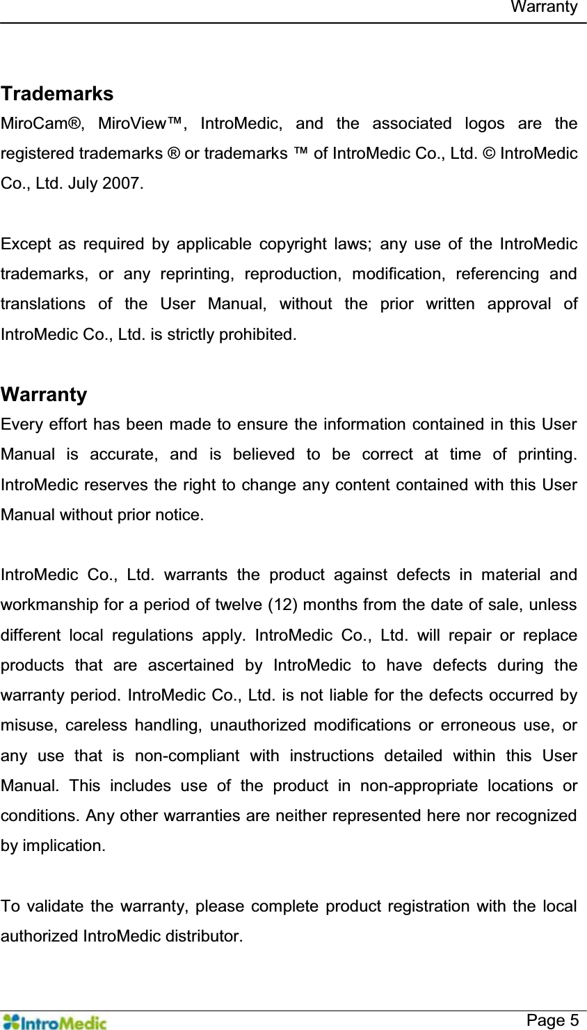
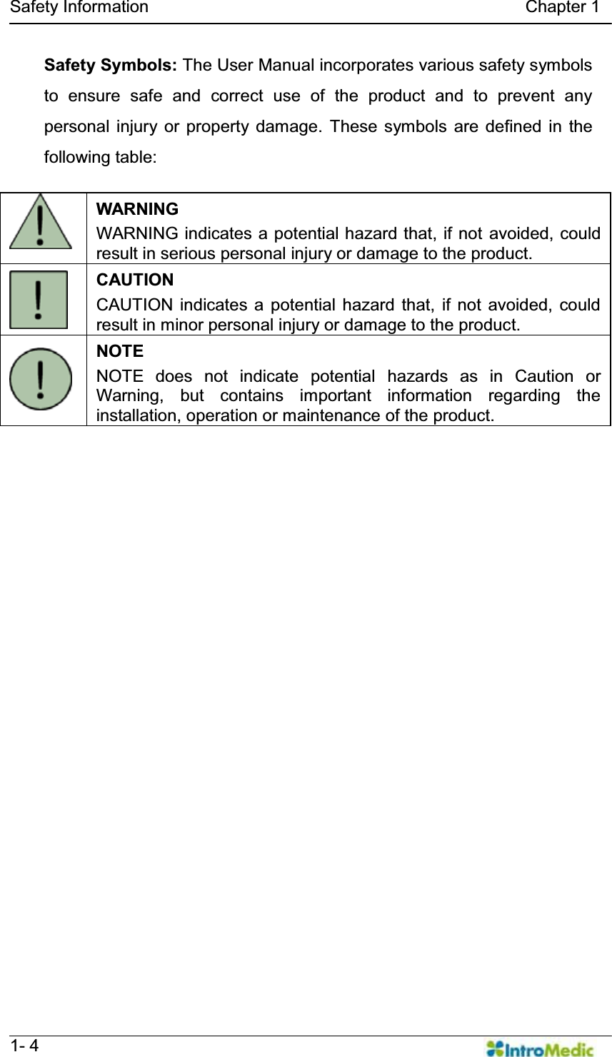
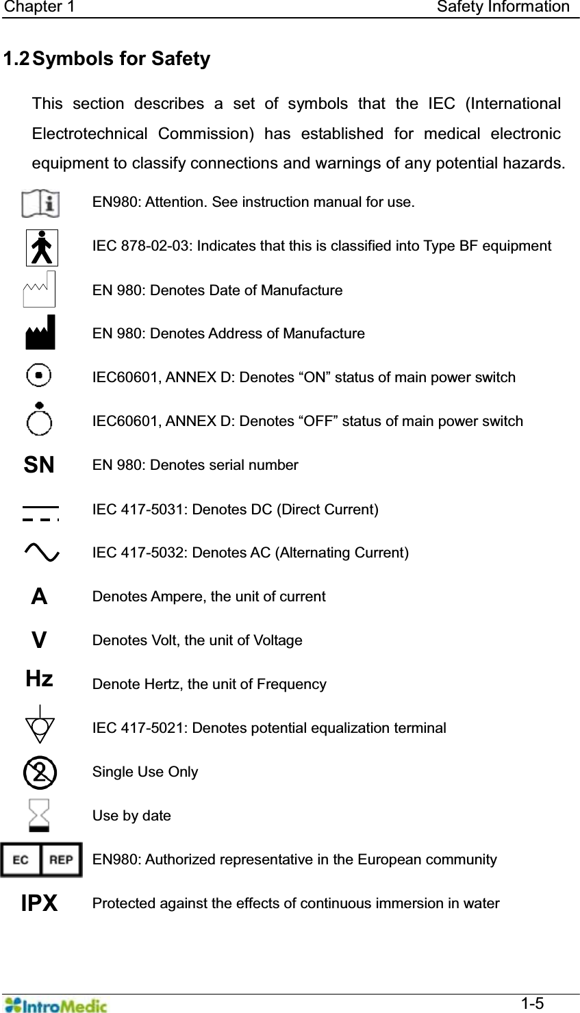
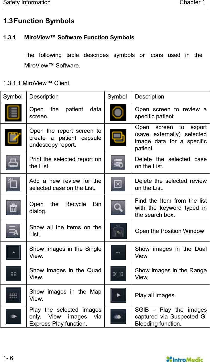
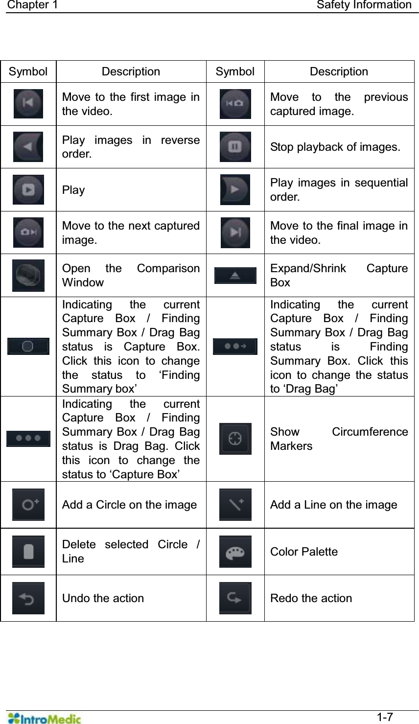
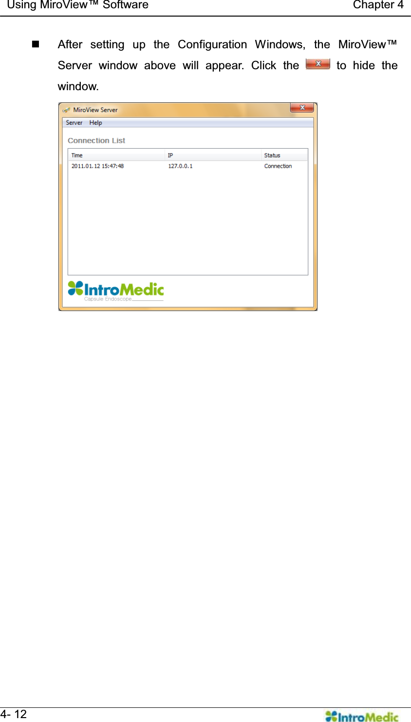
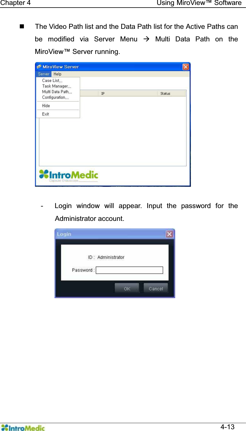
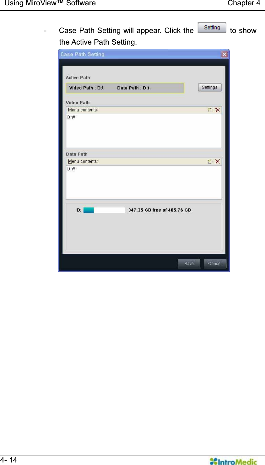
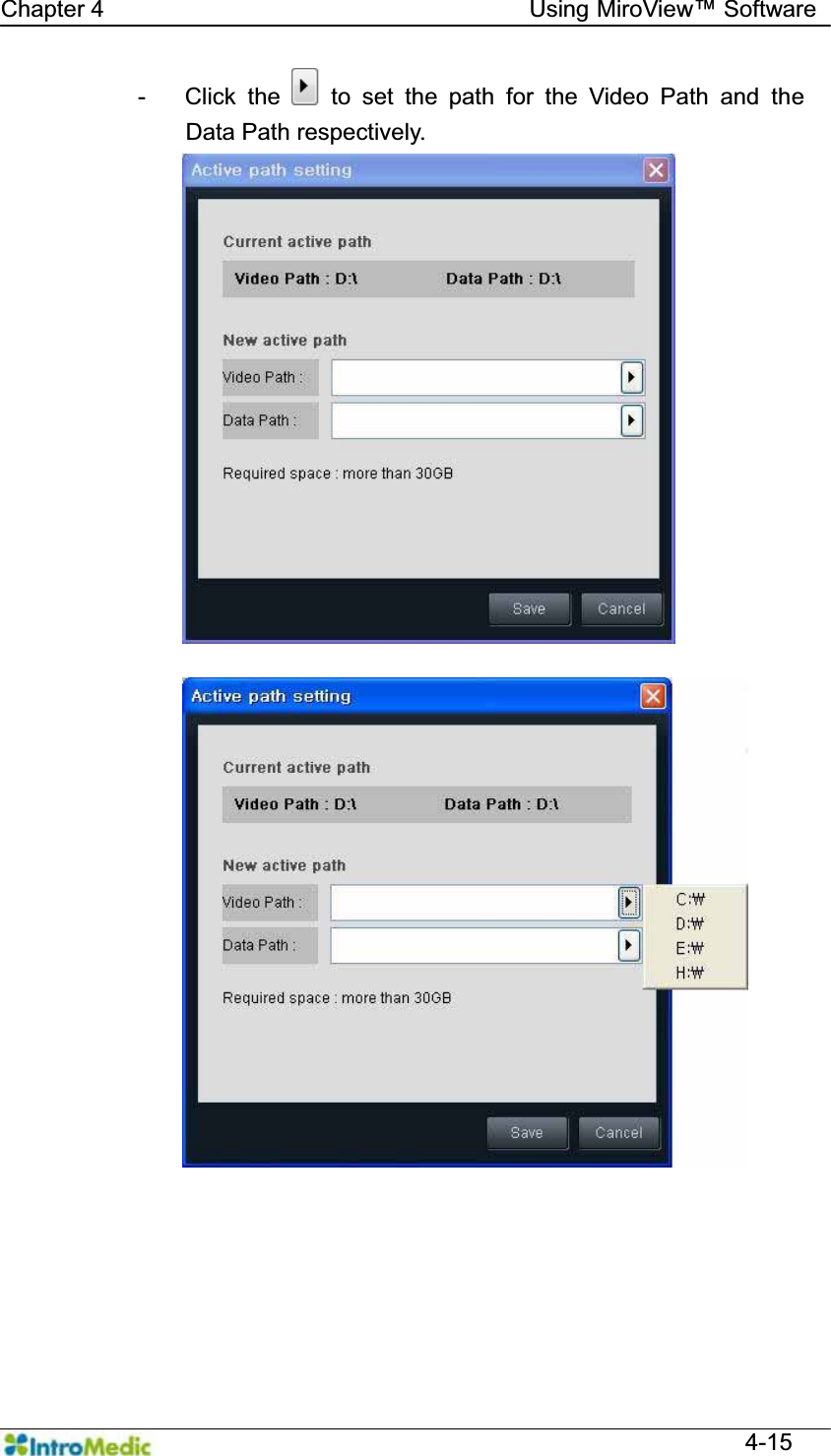
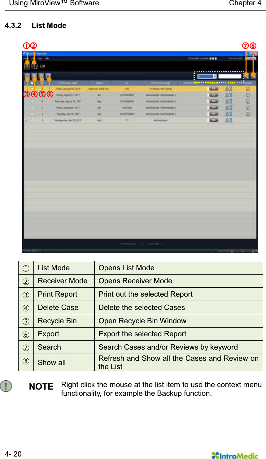
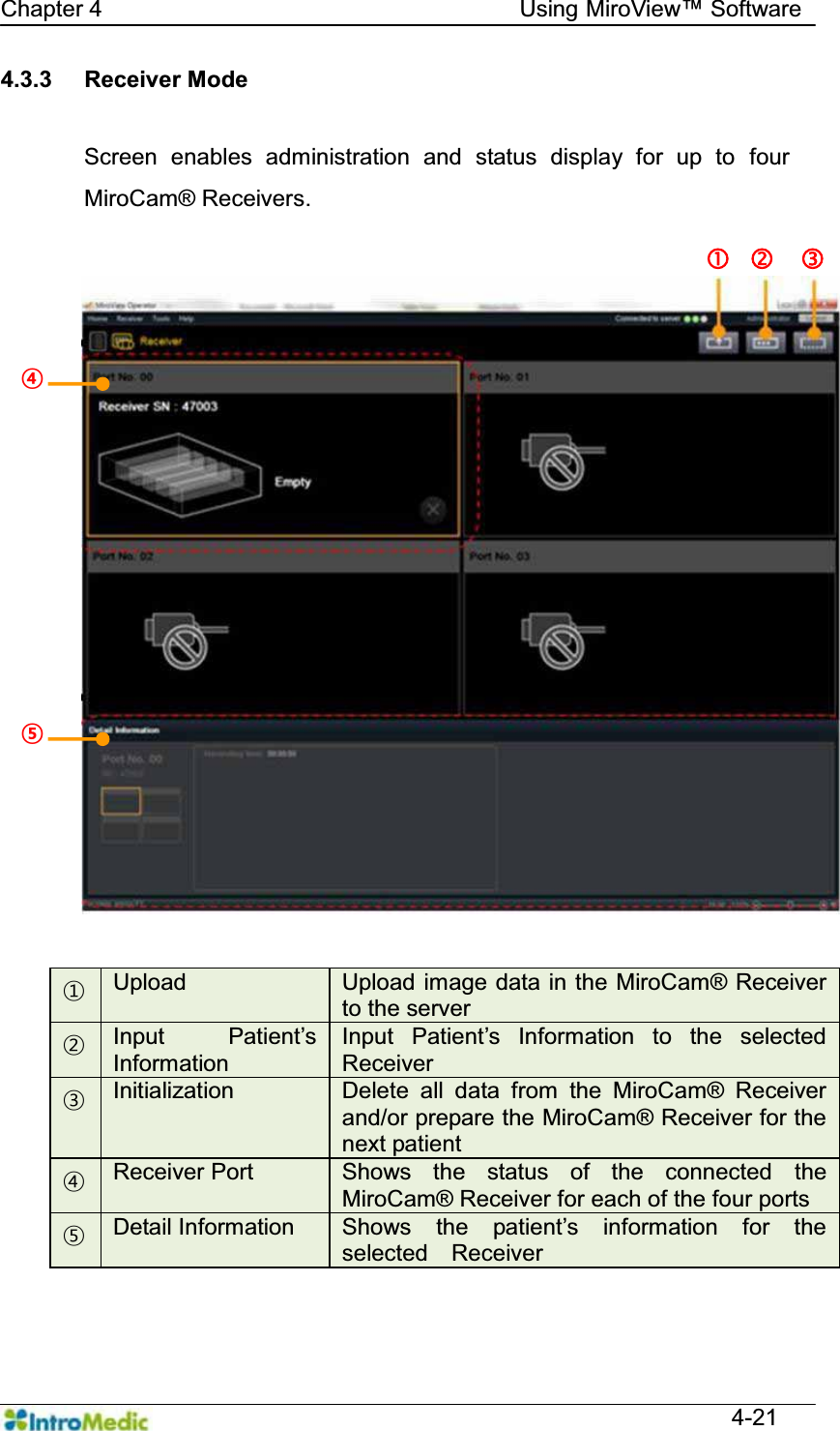
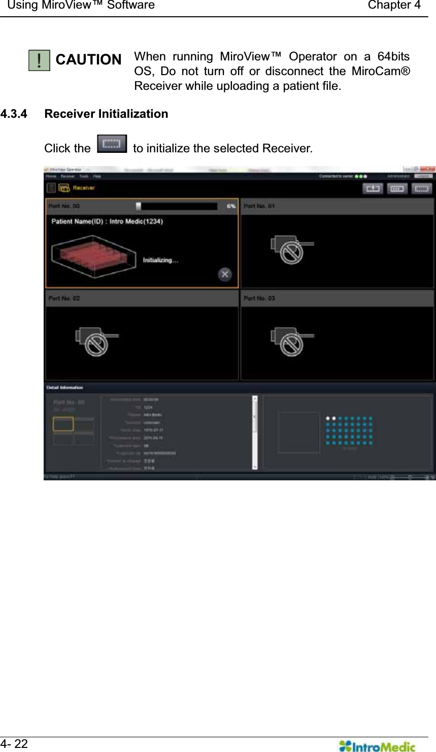
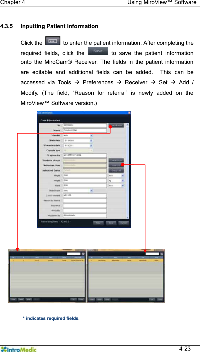
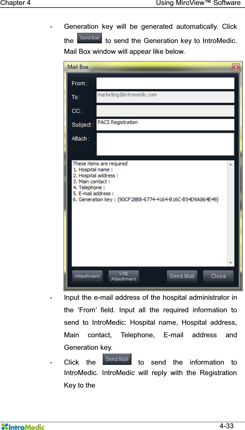
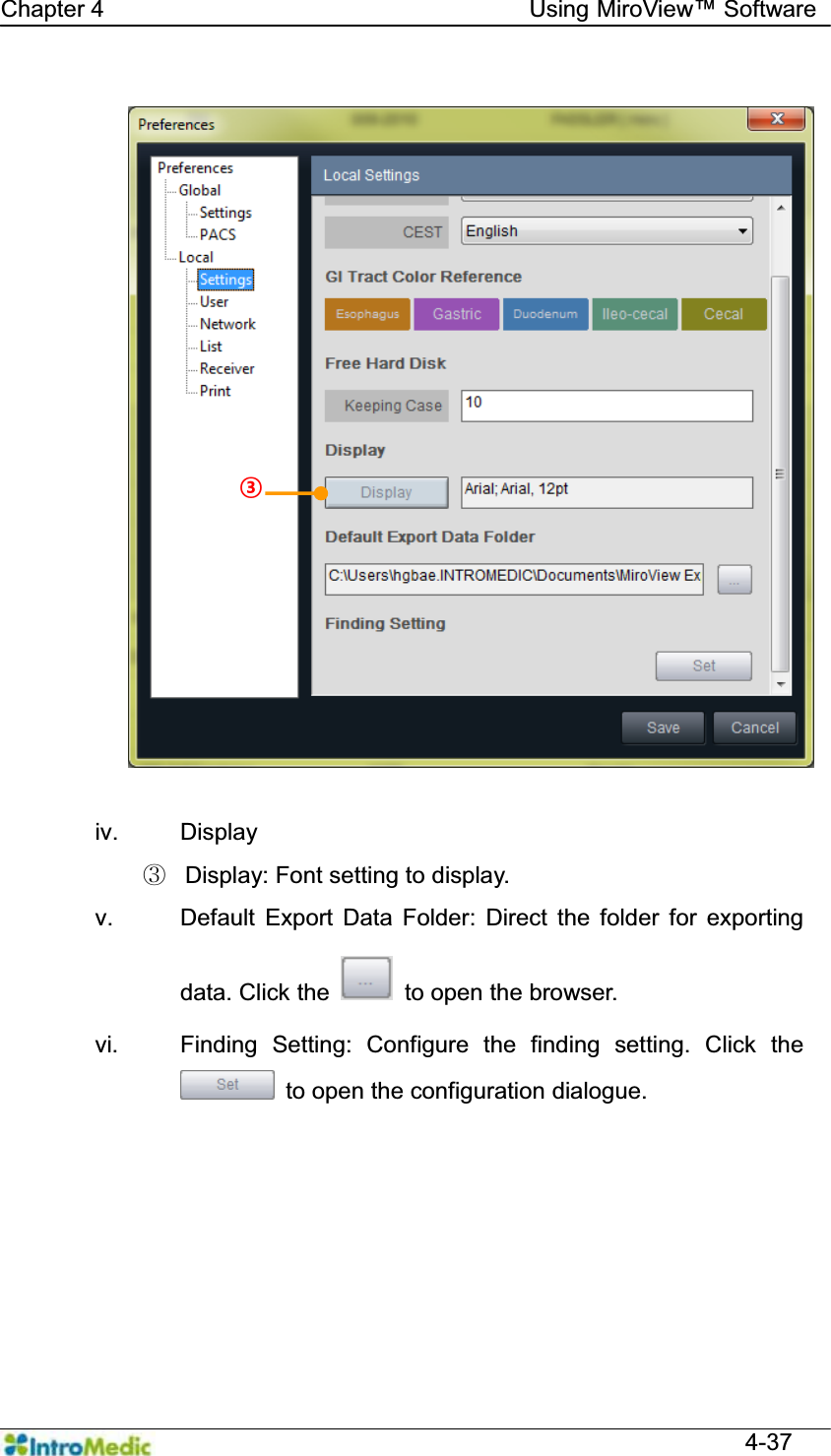
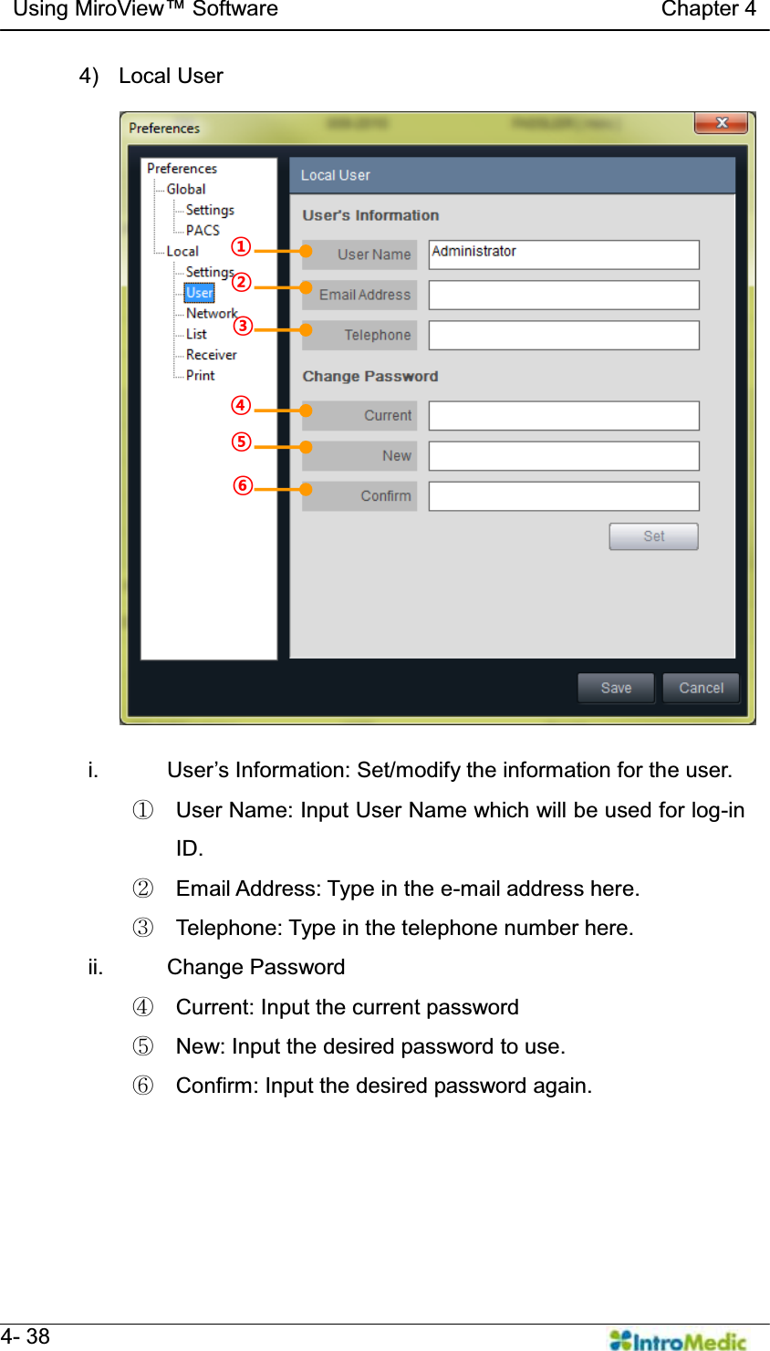
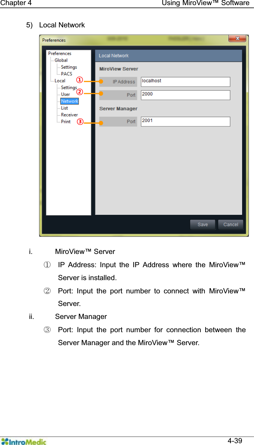
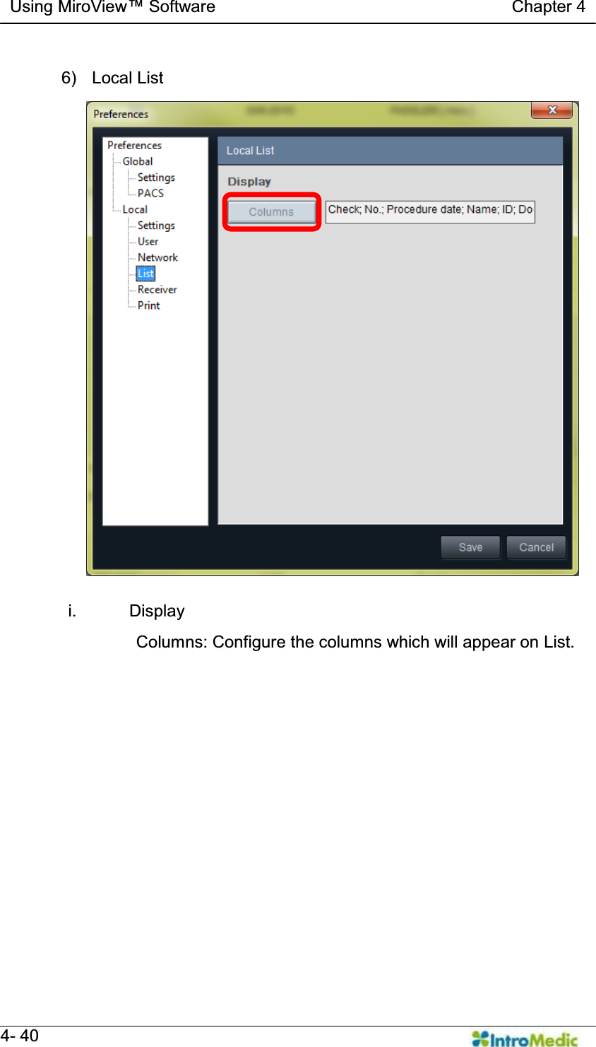
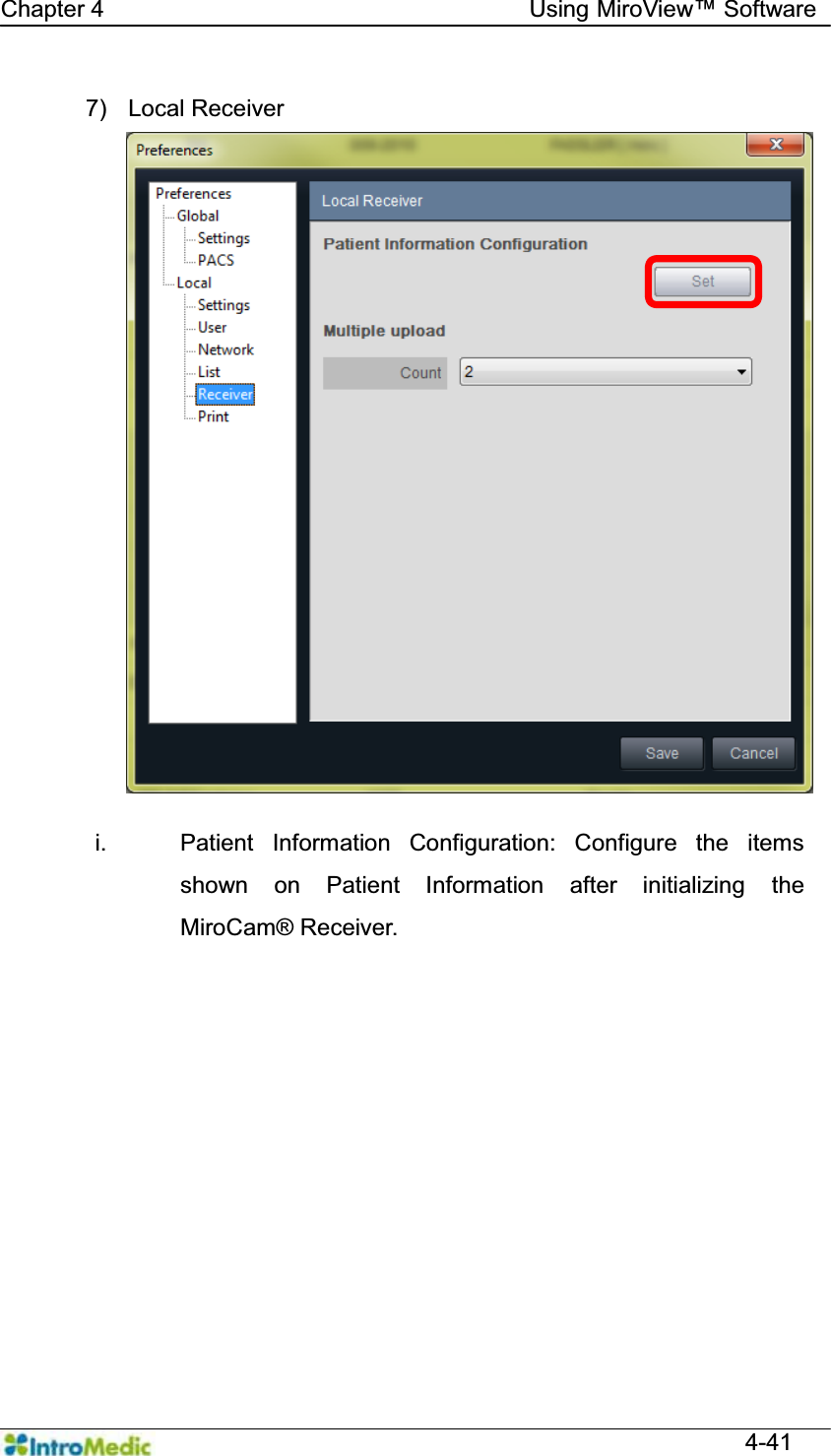
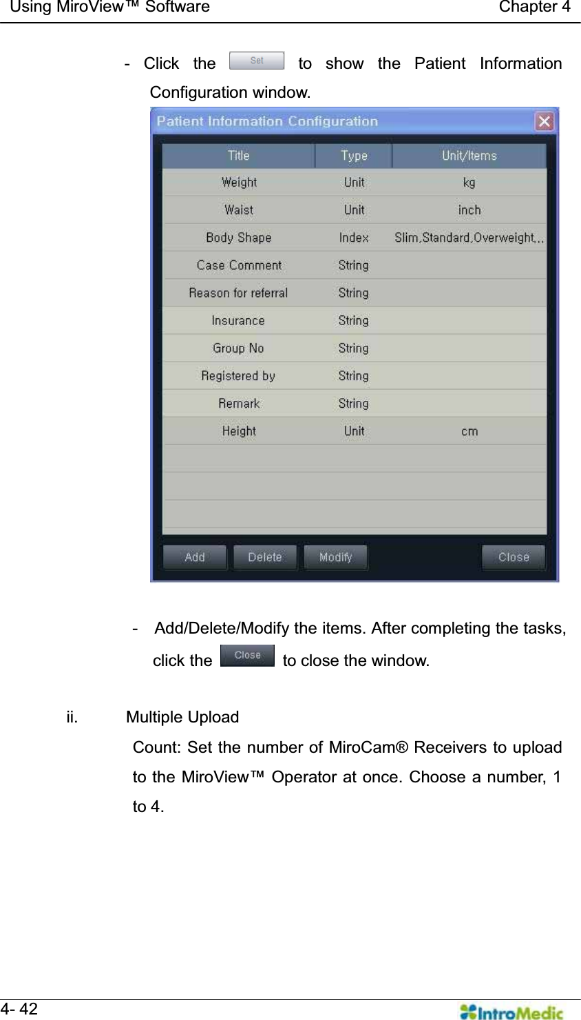
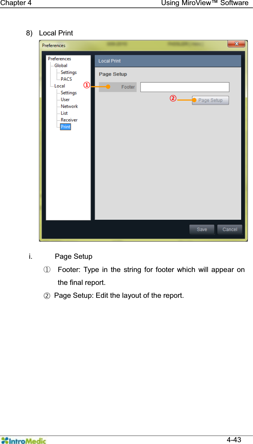
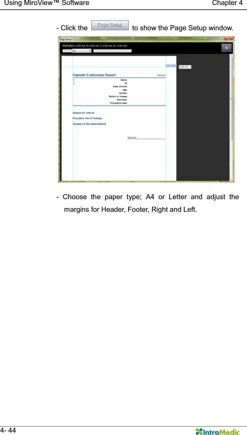
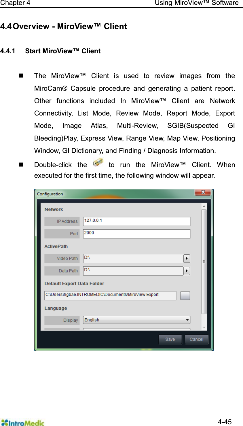
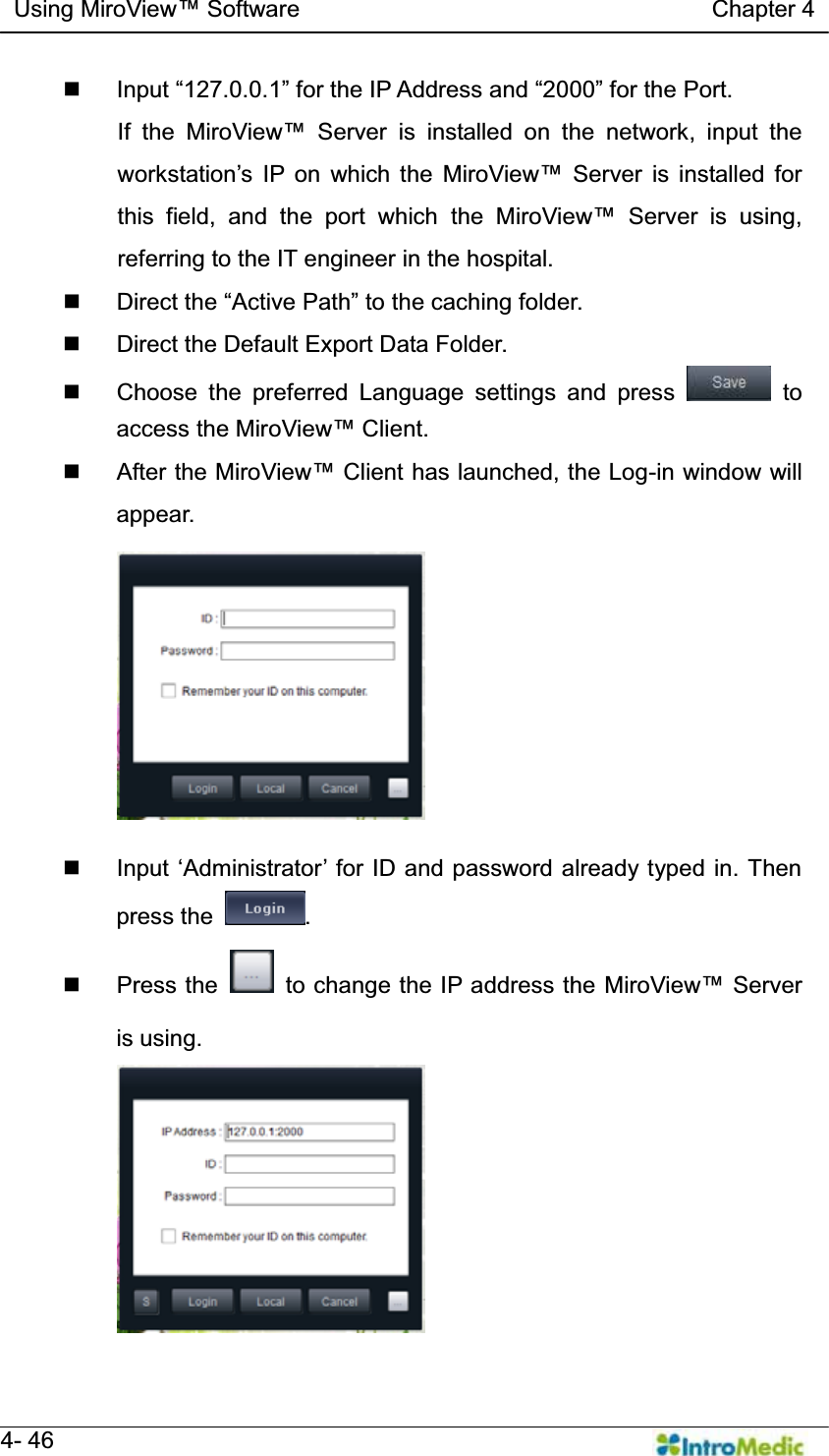
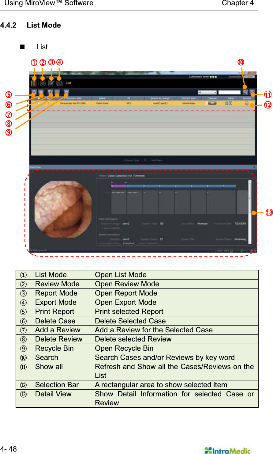
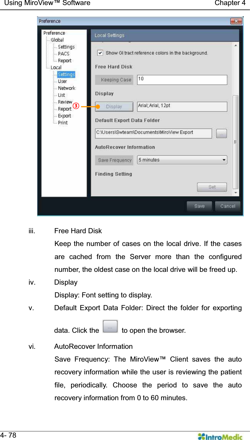
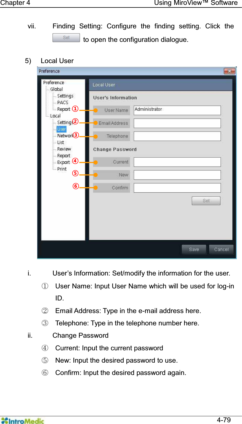
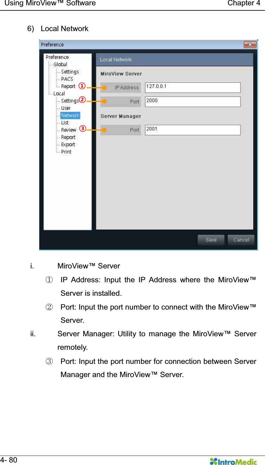
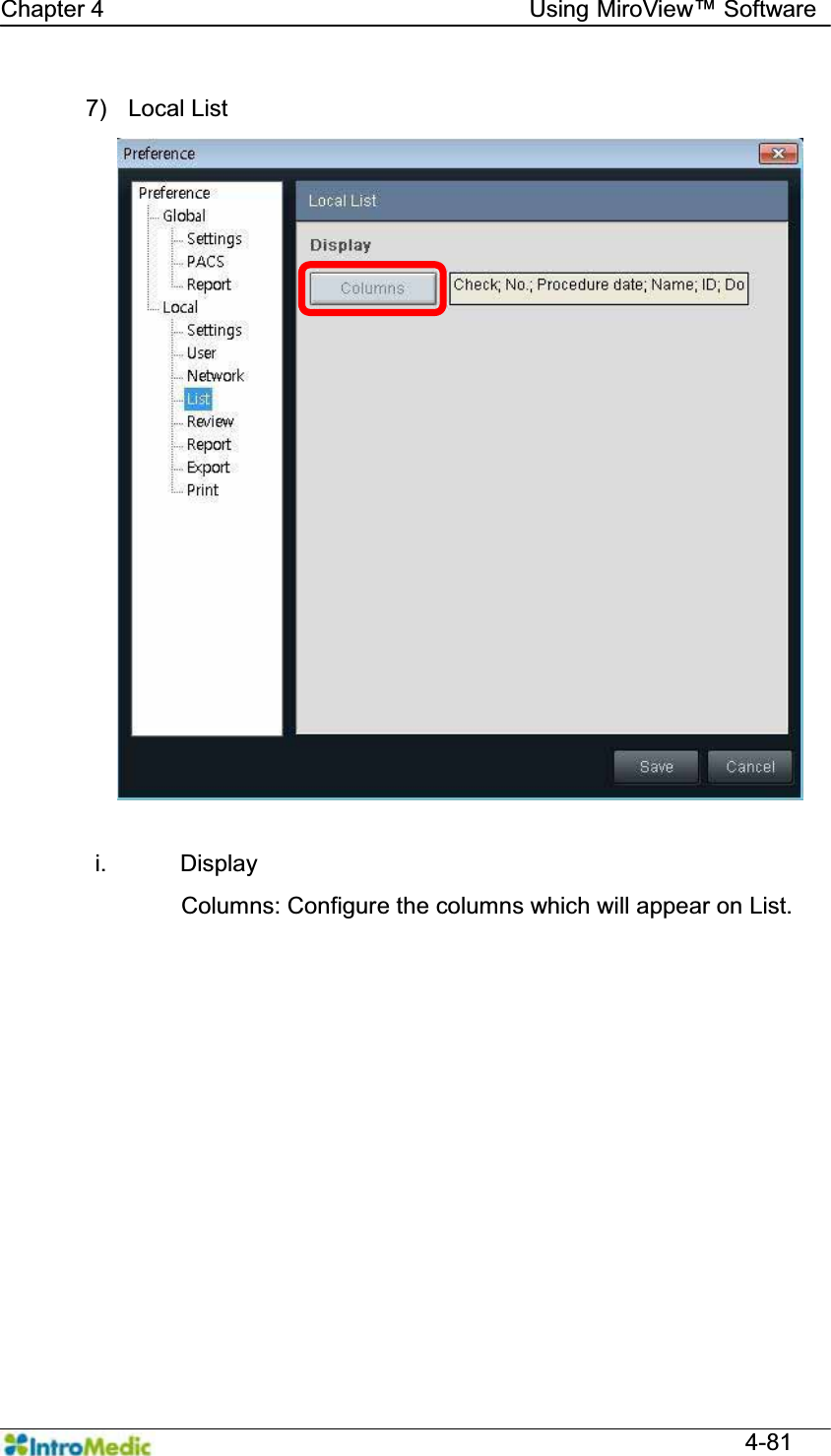
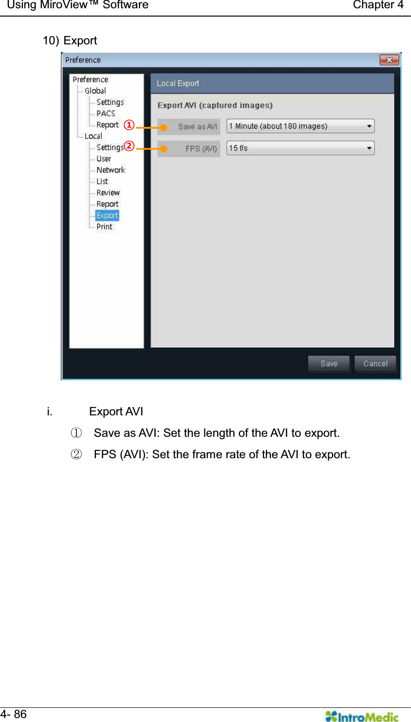
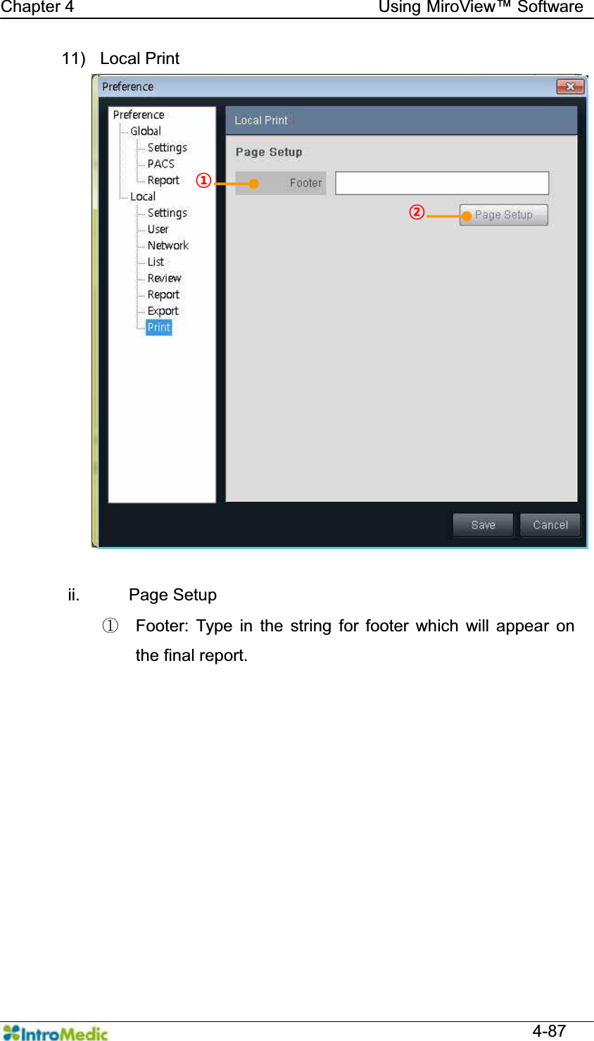
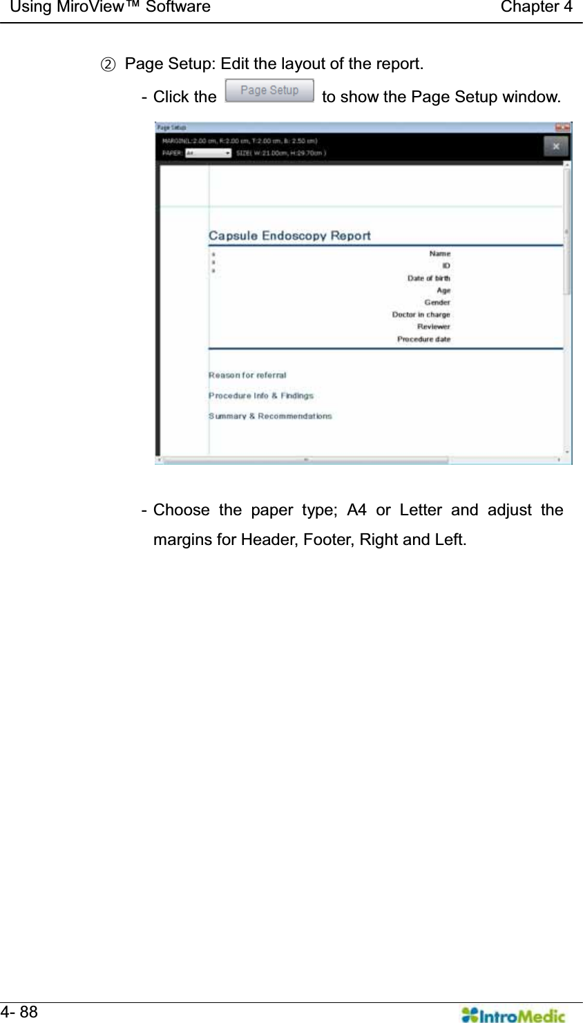
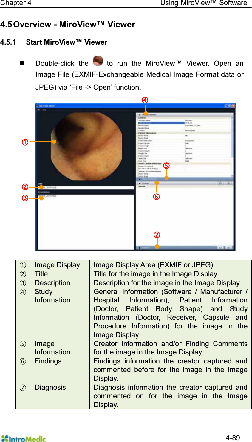
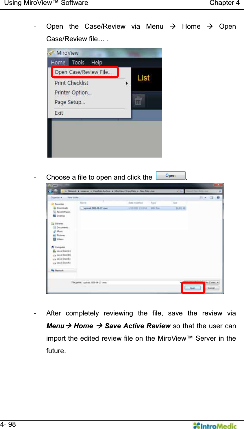
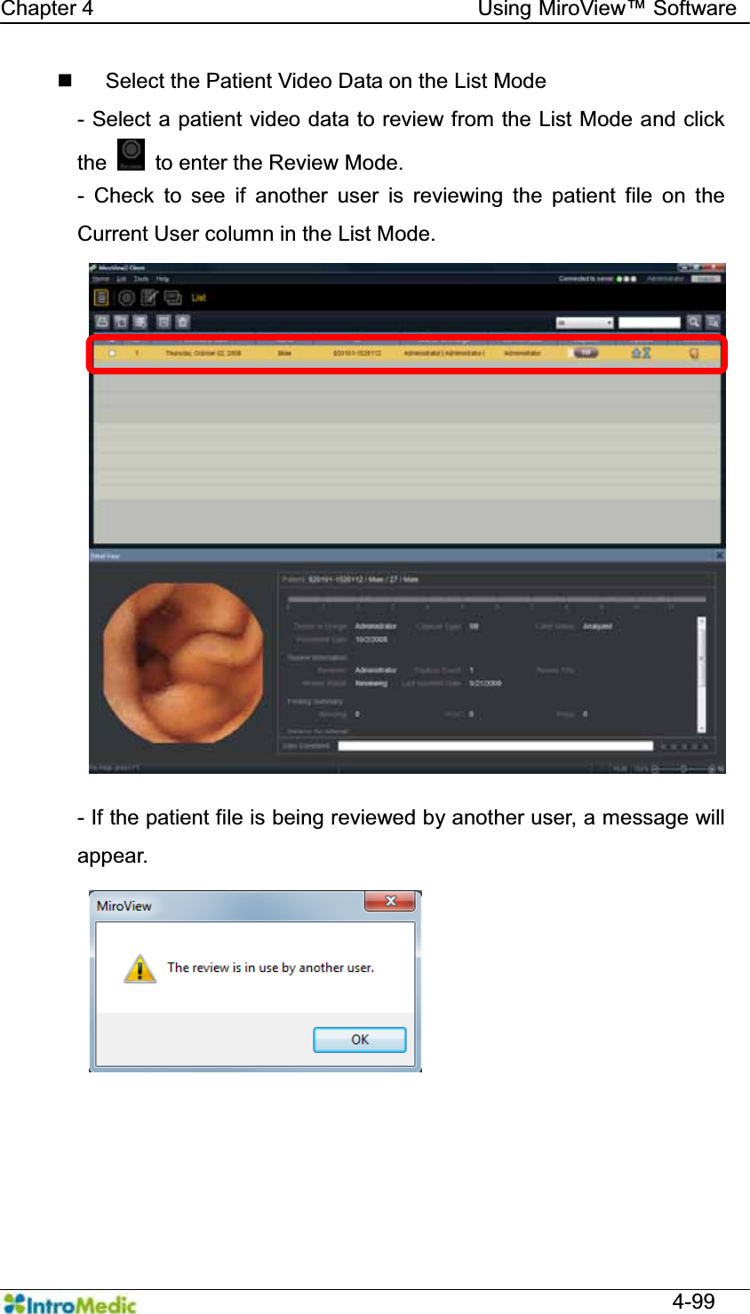
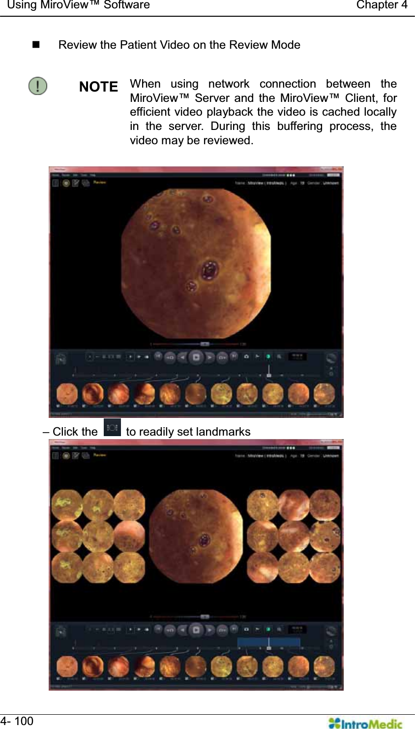
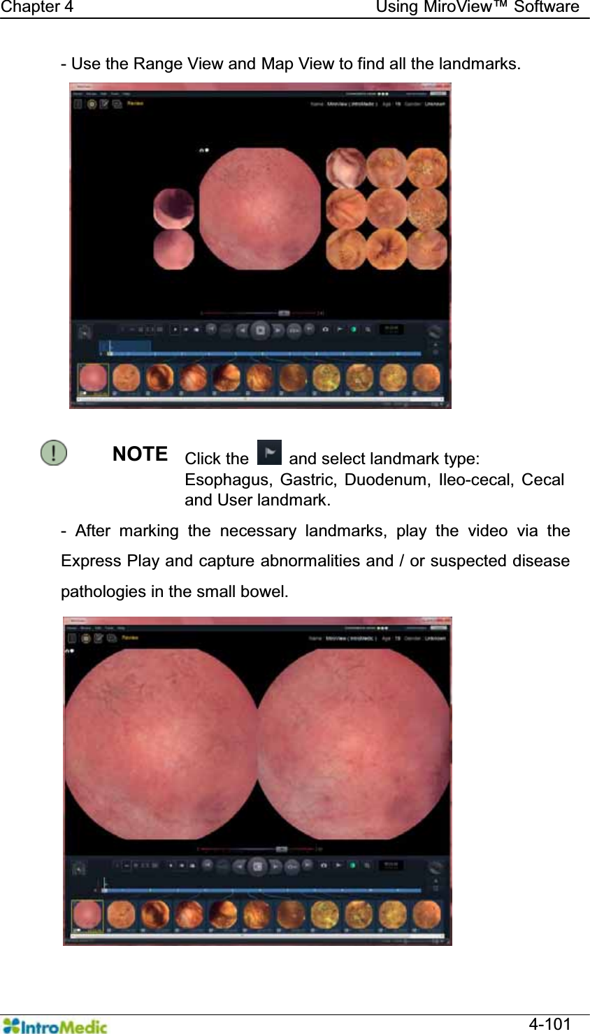
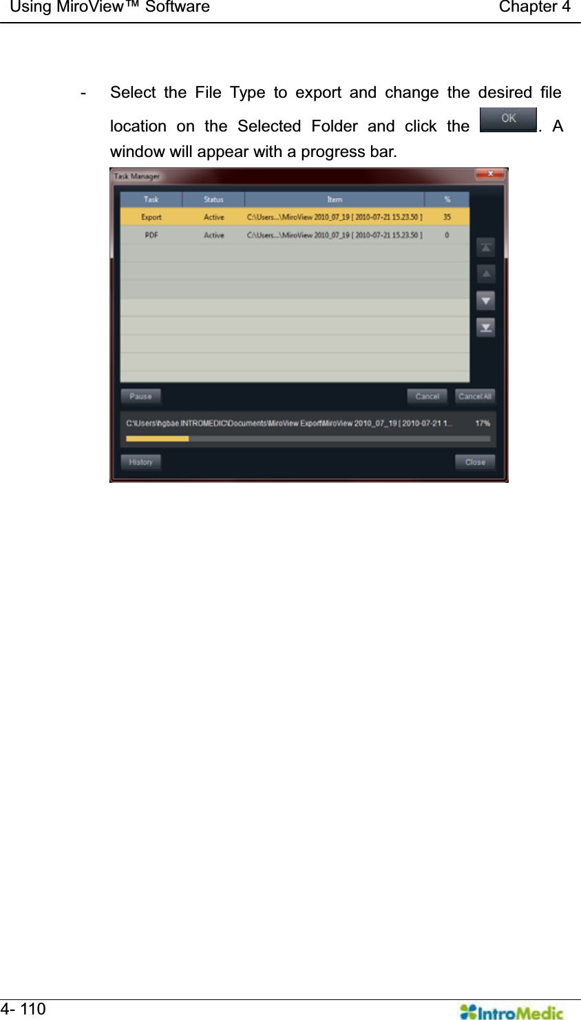
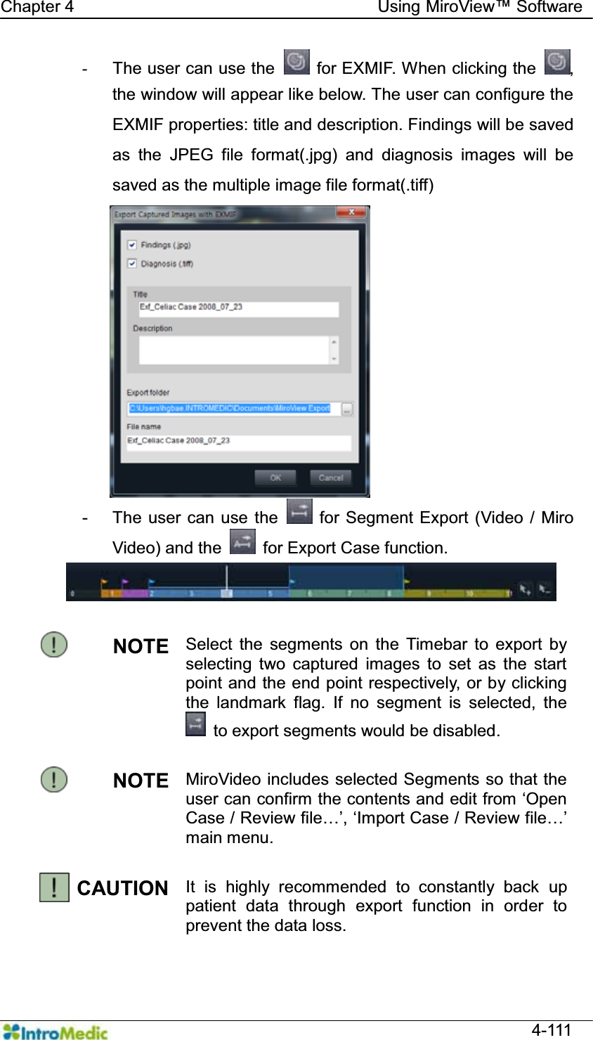
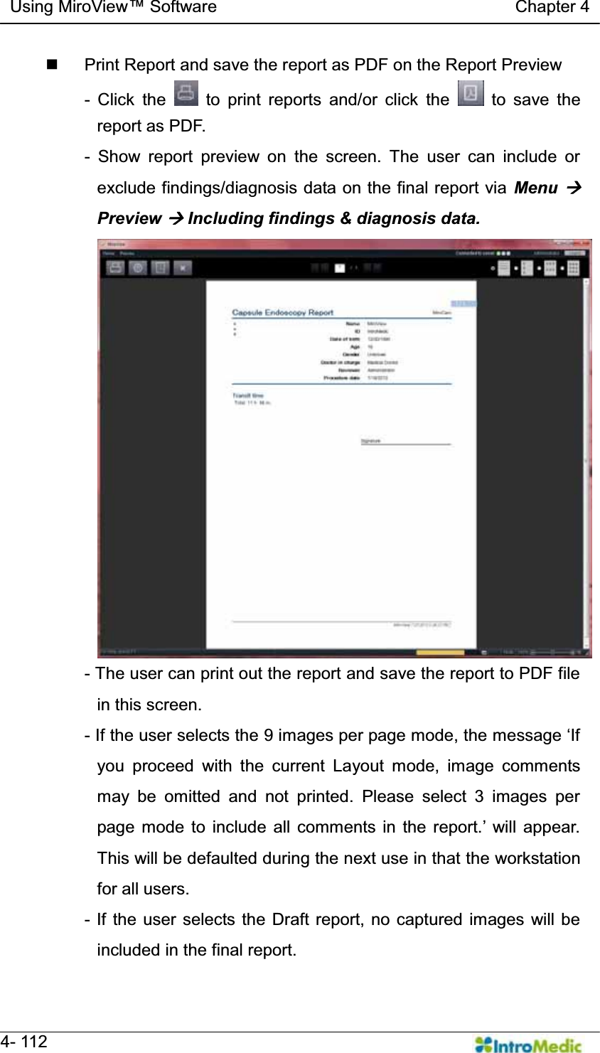
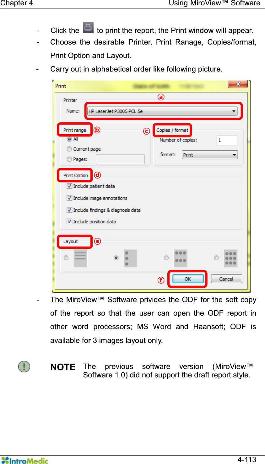
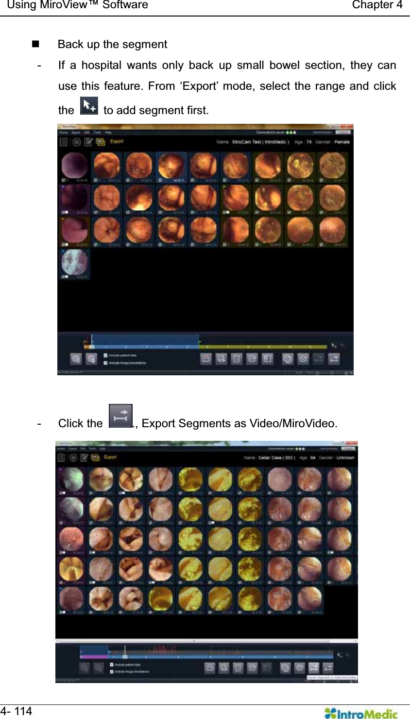
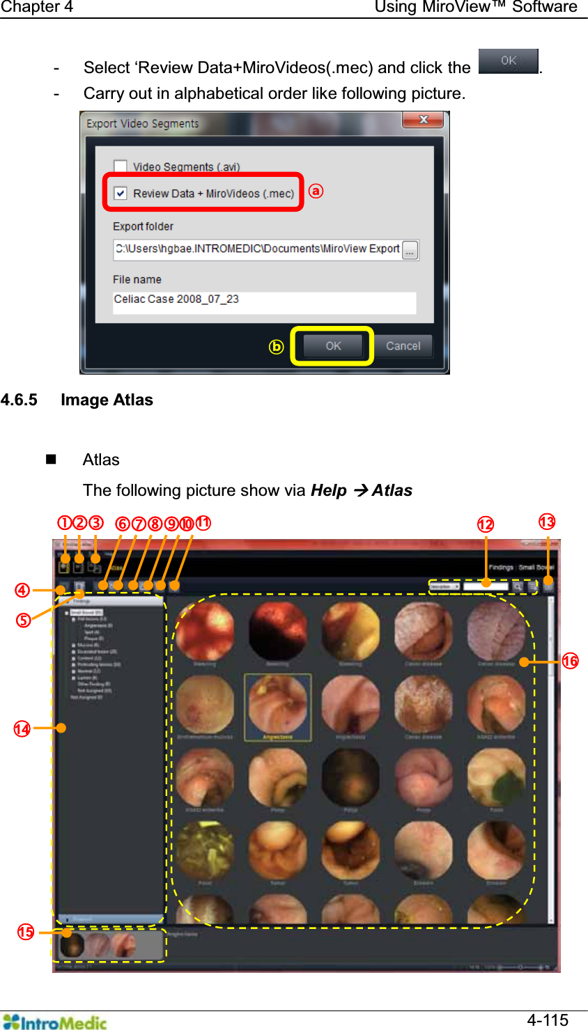
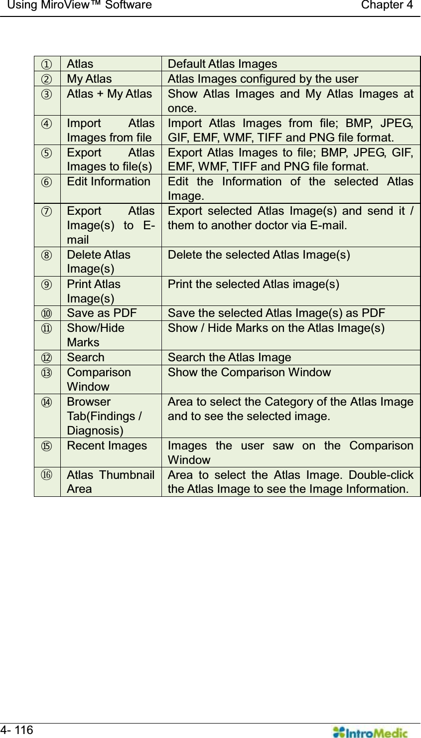
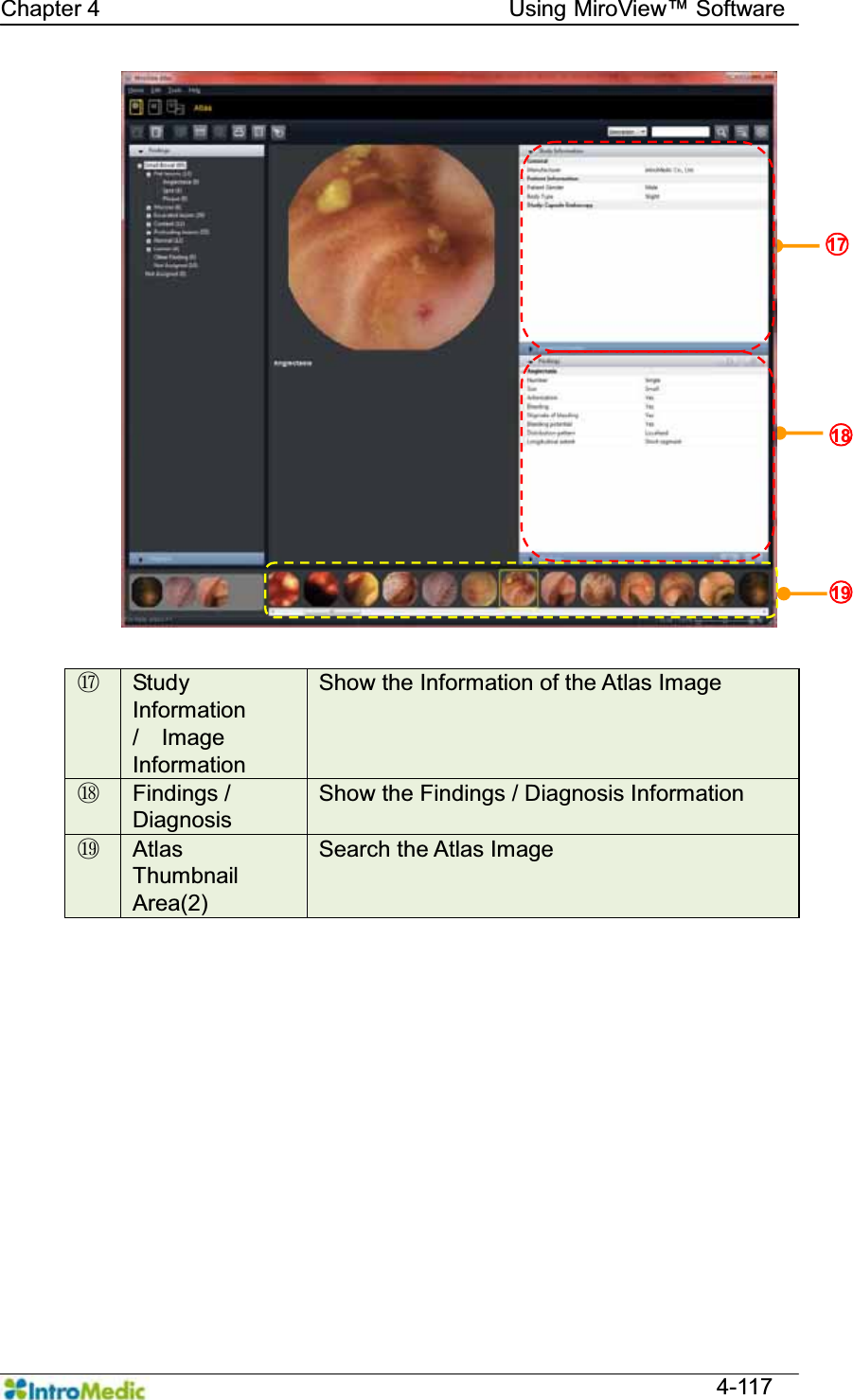
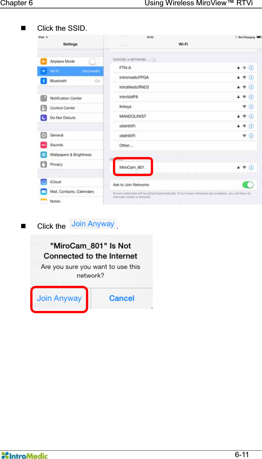
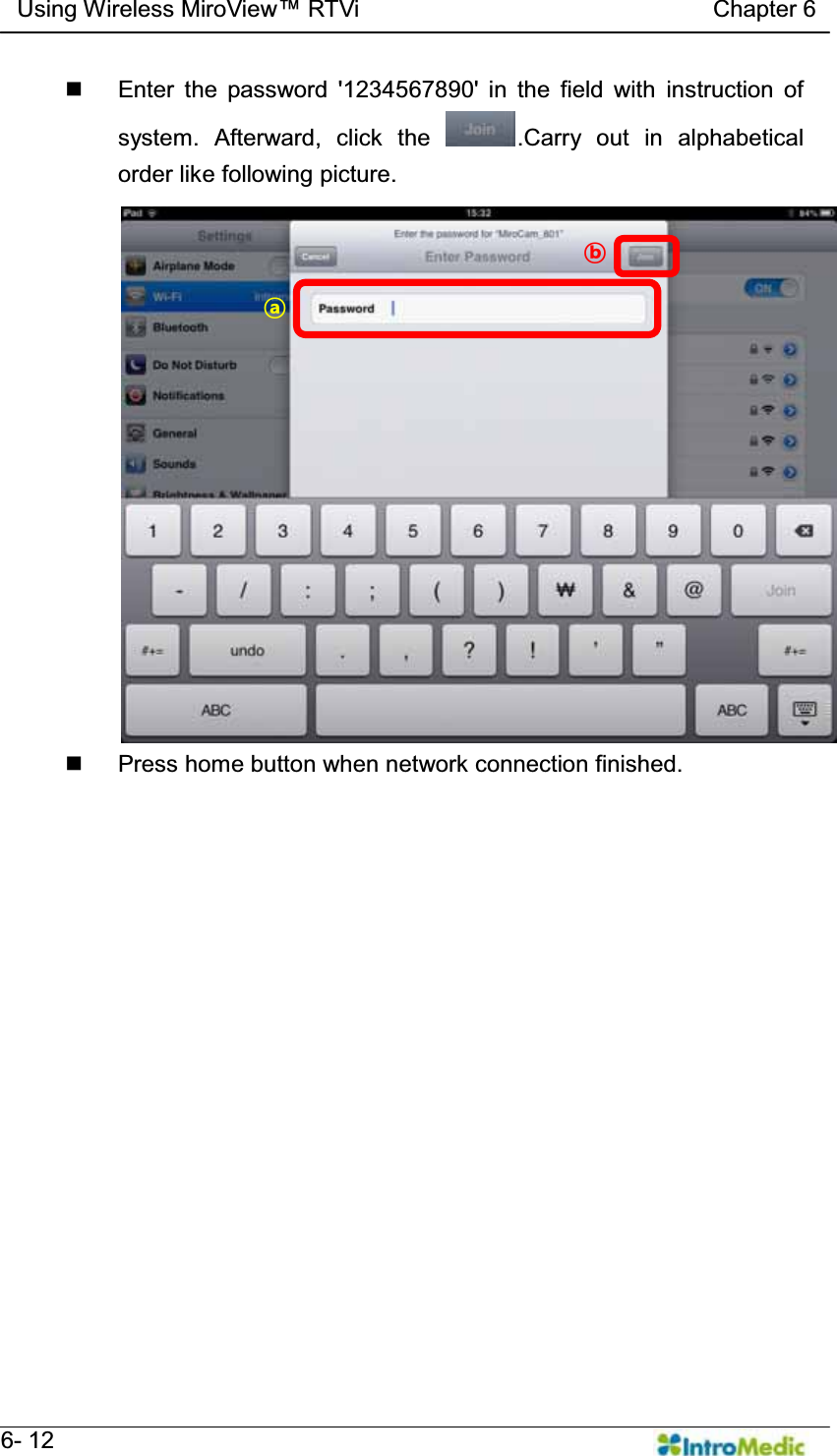
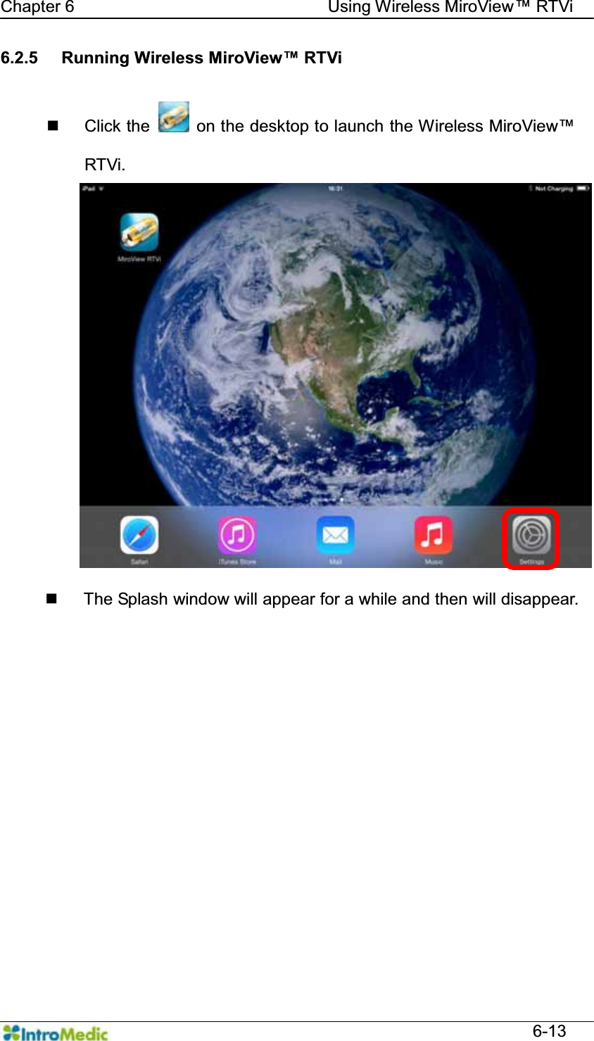
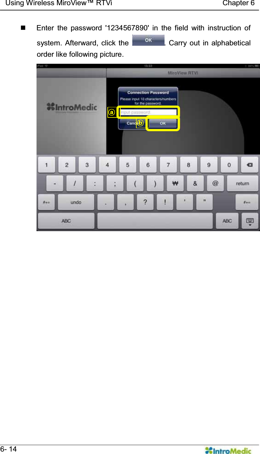
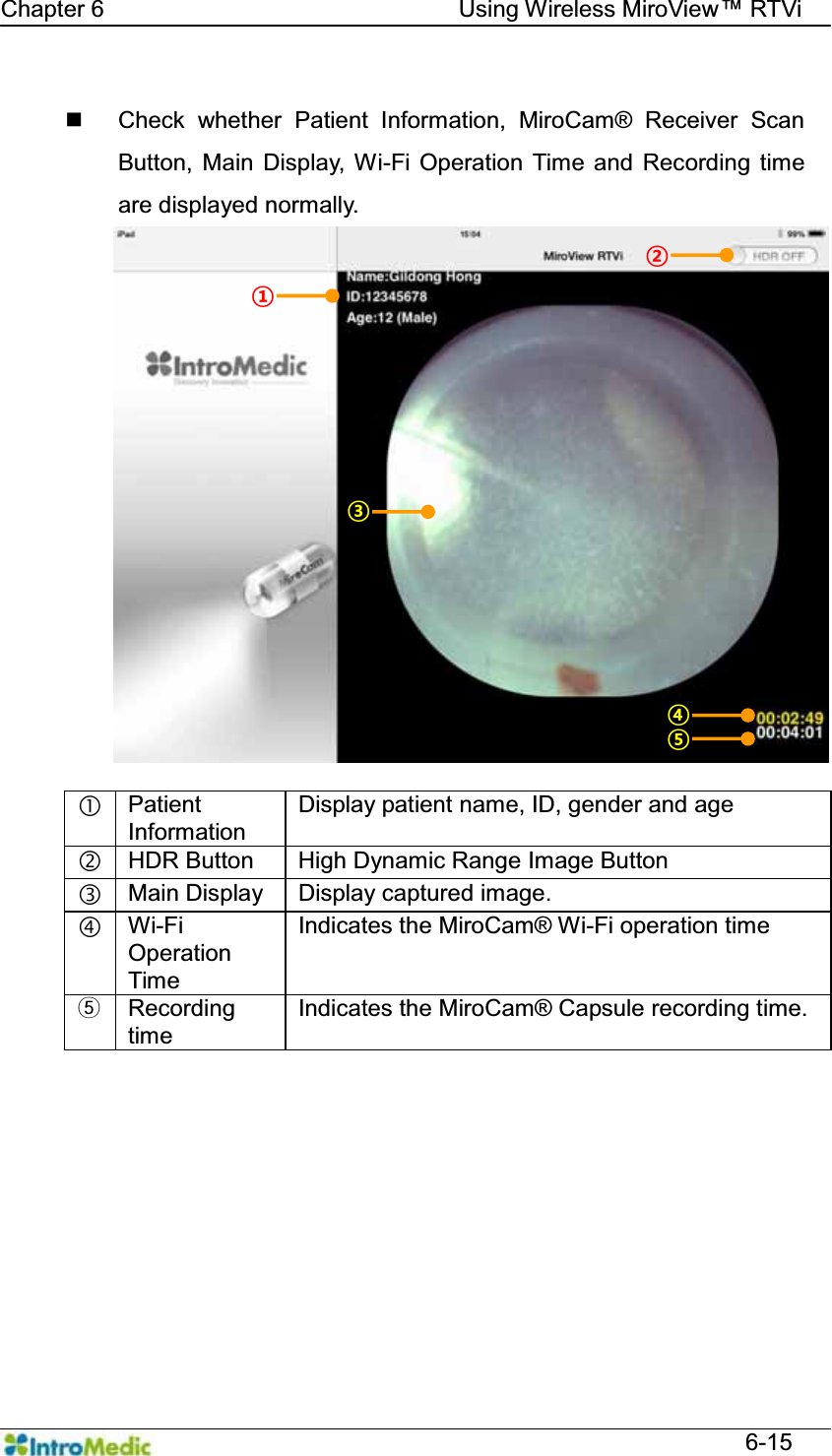
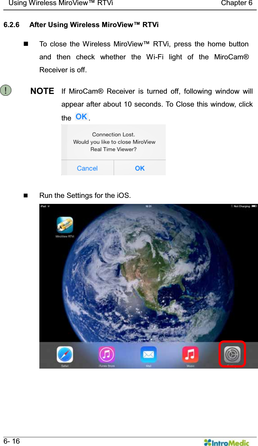
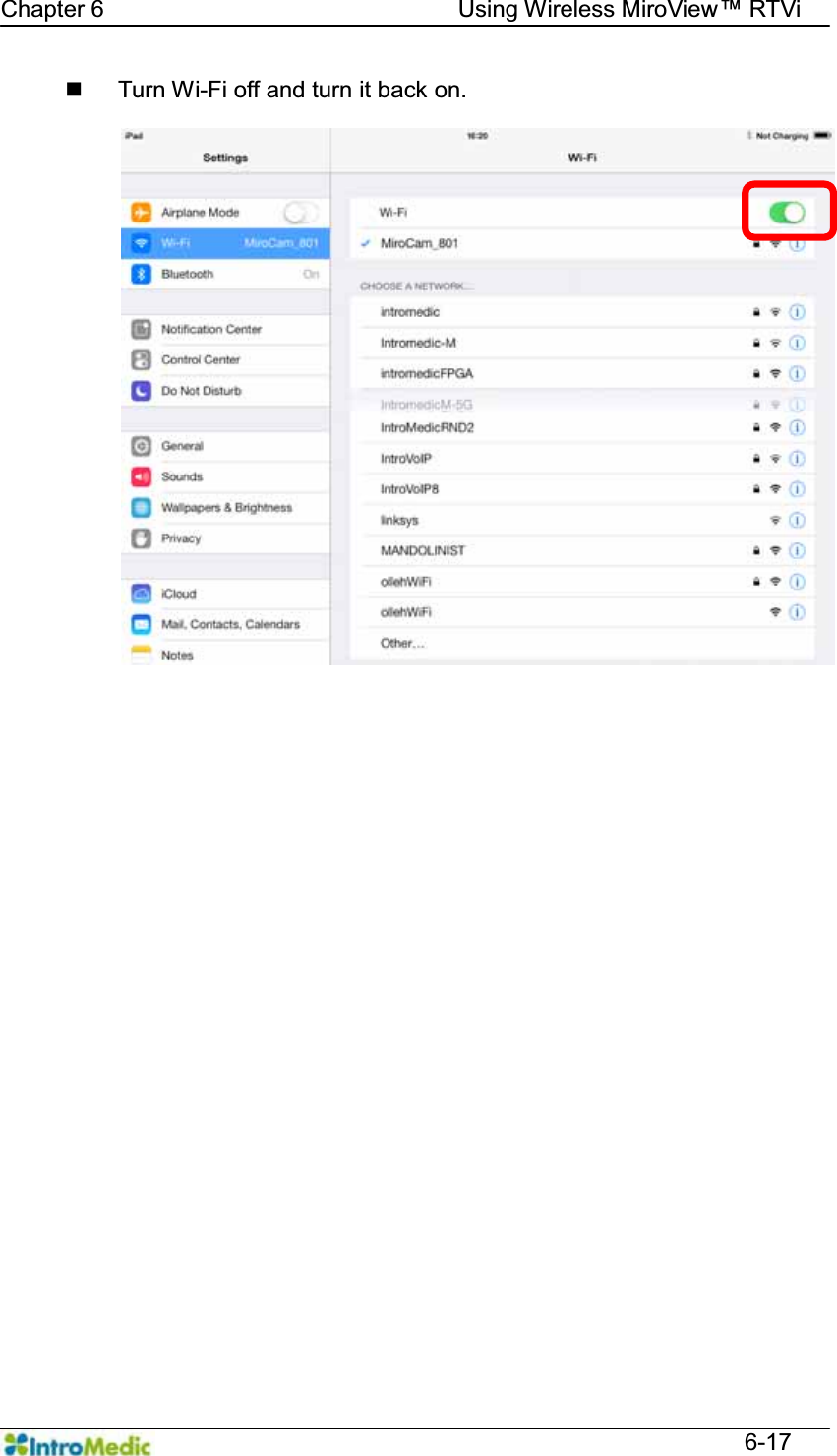
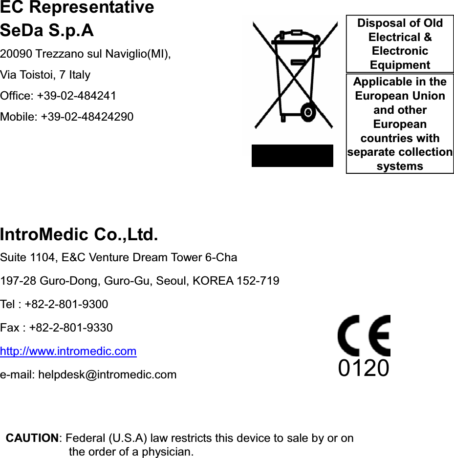
![Warranty Page 6 Exclusive warranty service The warranty service provided hereby is applicable exclusively to the purchaser of the product. IntroMedic will only warranty the product for purposes and usage as defined in this User Manual. Any usage not heeding the warnings, cautions and recommended usages as defined in this manual will nullify the warranty. Support For warranty or repair service please contact the local authorized IntroMedic distributor. For customer service or support please contact your point of purchase or IntroMedic Co., Ltd. Service agreements are only applicable to products of IntroMedic Co., Ltd. IntroMedic Customer Service TEL: 82-2-801-9300 FAX: 82-2-801-9330 http://www.intromedic.com E-mail: helpdesk@intromedic.com Safety Non-compliance with WKH XVHU¶V PDQXDO XQDXWKRUL]HG PRGLILFDWLRQV RI WKHproduct or replacement of parts, and/or opening of the product casing is prohibited and may be hazardous. Declaration on translation of labeling Based on buyer's request, IntroMedic will provide the labeling, such as ID label, Instruction for use and other promotional materials, which is translated into the national language(s) of European countries. And it will be evaluated by the local language expert, and will be confirmed by the native speaker of the local language.](https://usermanual.wiki/Intromedic/INTROMEDIC5/User-Guide-2179691-Page-6.png)