Intromedic INTROMEDIC5 CAPSULE ENDOSCOPE SYSTEM User Manual
Intromedic Co., Ltd. CAPSULE ENDOSCOPE SYSTEM
User Manual

User Manual

Copyright© 2011 IntroMedic Co., Ltd. MM1100-U-1311
Version 3.00 Date: 2013-11-21
User Manual

Warranty
Page 5
Trademarks
MiroCam®, 0LUR9LHZ, IntroMedic, and the associated logos are the
registered trademarks RUWUDGHPDUNVof IntroMedic Co., Ltd. © IntroMedic
Co., Ltd. July 2007.
Except as required by applicable copyright laws; any use of the IntroMedic
trademarks, or any reprinting, reproduction, modification, referencing and
translations of the User Manual, without the prior written approval of
IntroMedic Co., Ltd. is strictly prohibited.
Warranty
Every effort has been made to ensure the information contained in this User
Manual is accurate, and is believed to be correct at time of printing.
IntroMedic reserves the right to change any content contained with this User
Manual without prior notice.
IntroMedic Co., Ltd. warrants the product against defects in material and
workmanship for a period of twelve (12) months from the date of sale, unless
different local regulations apply. IntroMedic Co., Ltd. will repair or replace
products that are ascertained by IntroMedic to have defects during the
warranty period. IntroMedic Co., Ltd. is not liable for the defects occurred by
misuse, careless handling, unauthorized modifications or erroneous use, or
any use that is non-compliant with instructions detailed within this User
Manual. This includes use of the product in non-appropriate locations or
conditions. Any other warranties are neither represented here nor recognized
by implication.
To validate the warranty, please complete product registration with the local
authorized IntroMedic distributor.

Warranty
Page 6
Exclusive warranty service
The warranty service provided hereby is applicable exclusively to the
purchaser of the product. IntroMedic will only warranty the product for
purposes and usage as defined in this User Manual. Any usage not heeding
the warnings, cautions and recommended usages as defined in this manual
will nullify the warranty.
Support
For warranty or repair service please contact the local authorized IntroMedic
distributor.
For customer service or support please contact your point of purchase or
IntroMedic Co., Ltd. Service agreements are only applicable to products of
IntroMedic Co., Ltd.
IntroMedic Customer Service
TEL: 82-2-801-9300
FAX: 82-2-801-9330
http://www.intromedic.com
E-mail: helpdesk@intromedic.com
Safety
Non-compliance with WKH XVHU¶V PDQXDO XQDXWKRUL]HG PRGLILFDWLRQV RI WKH
product or replacement of parts, and/or opening of the product casing is
prohibited and may be hazardous.
Declaration on translation of labeling
Based on buyer's request, IntroMedic will provide the labeling, such as ID
label, Instruction for use and other promotional materials, which is translated
into the national language(s) of European countries. And it will be evaluated
by the local language expert, and will be confirmed by the native speaker of
the local language.

Contents
Page 7
CONTENTS
1. SAFETY INFORMATION 1-3
1.1 Warnings 1-3
1.2 Symbols for Safety 1-5
1.3 Function Symbols 1-6
1.4 Notes for Safe Use 1-11
2. SYSTEM OVERVIEW 2-3
2.1 Intended Purpose 2-3
2.2 Observable Diseases 2-4
2.3 Product Warranty Period 2-6
2.4 Product Specification 2-7
3. PERFORMING CAPSULE ENDOSCOPY 3-3
3.1 General Comments 3-3
3.2 Safety Warnings 3-3
3.3 Examination Preparation 3-4
3.4 Patient Preparation 3-7
3.5 Sensor Placement & Capsule Ingestion 3-9
3.6 Using Magnetic Controller 3-18
3.7 Uploading Image Data 3-22
3.8 MiroCam® Receiver Management ² Post
Procedure 3-23

Contents
Page 8
4. 86,1*0,529,(: SOFTWARE 4-3
4.1 +:6SHFLILFDWLRQVIRU0LUR9LHZ6RIWZDUH 4-6
4.2 Overview ² 0LUR9LHZ6HUYHU 4-10
4.3 Overview - 0LUR9LHZ2SHUDWRU 4-17
4.4 Overview - 0LUR9LHZ&OLHQW 4-45
4.5 Overview - 0LUR9LHZ9LHZHU 4-89
4.6 Performing Capsule Endoscopy 4-90
4.7 How to import 0LUR9LHZSoftware 1.0 Files 4-123
5. 86,1*0,529,(:579 5-3
5.1 Overview 5-3
5.2 Using MiroView579 5-5
6. 86,1*:,5(/(660,529,(:579L 6-3
6.1 Overview 6-3
6.2 8VLQJ:LUHOHVV0LUR9LHZ579L 6-6

1
Safety Information

Safety Information Chapter 1
1- 2

Chapter 1 Safety Information
1-3
1. SAFETY INFORMATION
1.1 Warnings
MiroCam® Capsule Endoscope System has been manufactured to
conform with the International Standard for Medical Electrical
Equipment: IEC 60601-1, together with the Collateral Standard for
Electromagnetic Compatibility Requirement and Tests IEC 60601-1-2.
MiroCam® Capsule Endoscope System has been manufactured to
conform to the electric shock, fire and mechanical hazard standards as
defined in CAN/CSA C22.2 NO.601.1.
Based on request of the buyer, IntroMedic will provide the labeling, such
as ID labels, and the User Manual in the national language(s) of
European countries. Translated documents will be evaluated by a local
language expert, and will be confirmed by a native speaker of the
respective national language.

Safety Information Chapter 1
1- 4
Safety Symbols: The User Manual incorporates various safety symbols
to ensure safe and correct use of the product and to prevent any
personal injury or property damage. These symbols are defined in the
following table:
WARNING
WARNING indicates a potential hazard that, if not avoided, could
result in serious personal injury or damage to the product.
CAUTION
CAUTION indicates a potential hazard that, if not avoided, could
result in minor personal injury or damage to the product.
NOTE
NOTE does not indicate potential hazards as in Caution or
Warning, but contains important information regarding the
installation, operation or maintenance of the product.
Chapter 1 Safety Information
1-5
1.2 Symbols for Safety
This section describes a set of symbols that the IEC (International
Electrotechnical Commission) has established for medical electronic
equipment to classify connections and warnings of any potential hazards.
EN980: Attention. See instruction manual for use.
IEC 878-02-03: Indicates that this is classified into Type BF equipment
EN 980: Denotes Date of Manufacture
EN 980: Denotes Address of Manufacture
,(&$11(;''HQRWHV³21´VWDWXVRIPDLQSRZHUVZLWFK
,(&$11(;''HQRWHV³2))´VWDWXVRIPDLQSRZHUVZLWFK
SN EN 980: Denotes serial number
IEC 417-5031: Denotes DC (Direct Current)
IEC 417-5032: Denotes AC (Alternating Current)
A Denotes Ampere, the unit of current
V Denotes Volt, the unit of Voltage
Hz Denote Hertz, the unit of Frequency
IEC 417-5021: Denotes potential equalization terminal
Single Use Only
Use by date
EN980: Authorized representative in the European community
IPX Protected against the effects of continuous immersion in water
Safety Information Chapter 1
1- 6
1.3 Function Symbols
1.3.1 0LUR9LHZSoftware Function Symbols
The following table describes symbols or icons used in the
MiroViewSoftware.
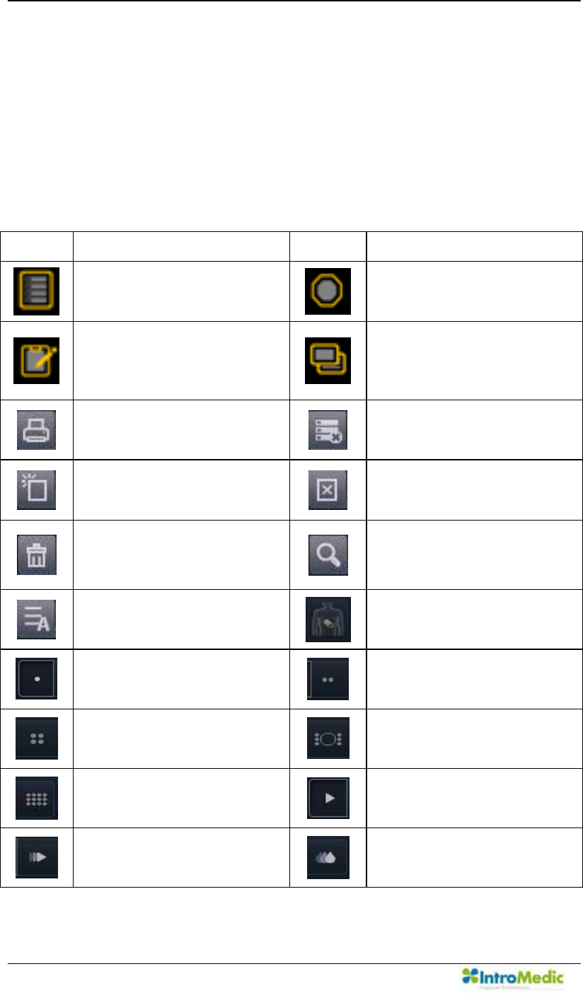
1.3.1.1 0LUR9LHZClient
Symbol
Description Symbol Description
Open the patient data
screen.
Open screen to review a
specific patient
Open the report screen to
create a patient capsule
endoscopy report.
Open screen to export
(save externally) selected
image data for a specific
patient.
Print the selected report on
the List.
Delete the selected case
on the List.
Add a new review for the
selected case on the List.
Delete the selected review
on the List.
Open the Recycle Bin
dialog.
Find the Item from the list
with the keyword typed in
the search box.
Show all the items on the
List.
Open the Position Window
Show images in the Single
View.
Show images in the Dual
View.
Show images in the Quad
View.
Show images in the Range
View.
Show images in the Map
View. Play all images.
Play the selected images
only. View images via
Express Play function.
SGIB - Play the images
captured via Suspected GI
Bleeding function.
Chapter 1 Safety Information
1-7
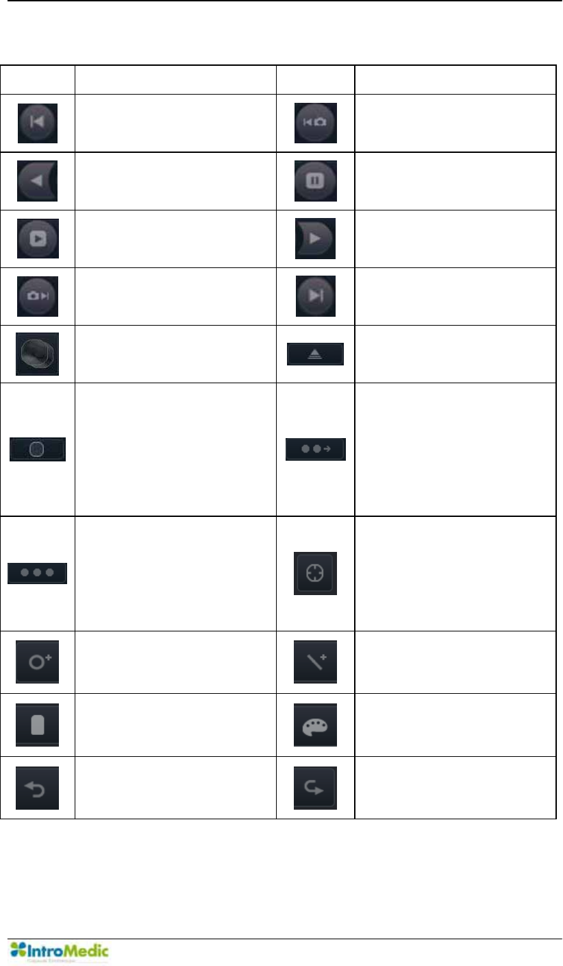
Symbol Description Symbol Description
Move to the first image in
the video.
Move to the previous
captured image.
Play images in reverse
order.
Stop playback of images.
Play
Play images in sequential
order.
Move to the next captured
image.
Move to the final image in
the video.
Open the Comparison
Window
Expand/Shrink Capture
Box
Indicating the current
Capture Box / Finding
Summary Box / Drag Bag
status is Capture Box.
Click this icon to change
WKH VWDWXV WR µ)LQGLQJ
6XPPDU\ER[¶
Indicating the current
Capture Box / Finding
Summary Box / Drag Bag
status is Finding
Summary Box. Click this
icon to change the status
WRµ'UDJ%DJ¶
Indicating the current
Capture Box / Finding
Summary Box / Drag Bag
status is Drag Bag. Click
this icon to change the
VWDWXVWRµ&DSWXUH%R[¶
Show Circumference
Markers
Add a Circle on the image
Add a Line on the image
Delete selected Circle /
Line
Color Palette
Undo the action
Redo the action
Safety Information Chapter 1
1- 8
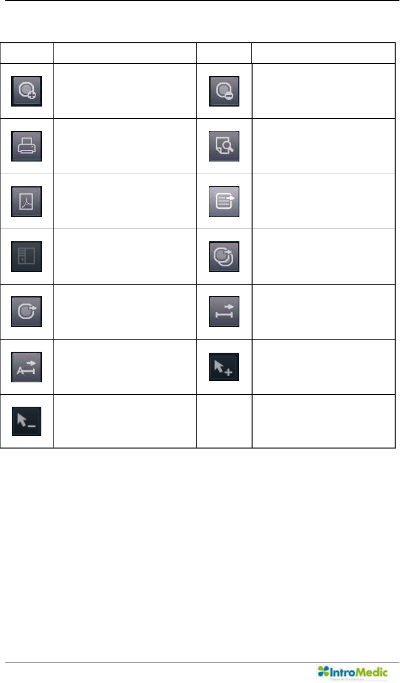
Symbol Description Symbol Description
Check the selected
captured images
Uncheck the selected
captured images
Print
Preview
Save as PDF
Export Review
Open PACS function
(Registered User Only)
Export Captured Images
with EXMIF
Export Captured Images
as Image / Video /
MiroVideo
Export Segments as
Image / Video / MiroVideo
Export Case as Video /
MiroVideo
Select the area as a
Segment
Deselect the area from
Segment
Chapter 1 Safety Information
1-9
1.3.1.2 0LUR9LHZOperator
Symbol Description
Symbol
Description
Open the patient data
screen.
Connect to the
MiroCam® Receiver and
open MiroCam® Receiver
control screen.
Print the selected report on
the List.
Delete the selected case
on the List.
Open the Recycle Bin
dialog.
Export the case selected
on the List.
Find the Item from the list
with the keyword typed in
the search box.
Show all the items on the
List.
Upload the image data from
the selected MiroCam®
Receivier
Show / Edit the patient
information for the
selected MiroCam®
Receiver
Initialize the selected
MiroCam® Receiver
Unconnected
Unformatted the
MiroCam® Receiver.
Empty the MiroCam®
Receiver.
Prepared the MiroCam®
Receiver.
Recorded the MiroCam®
Receiver.
Uploaded the MiroCam®
Receiver.
Safety Information Chapter 1
1- 10
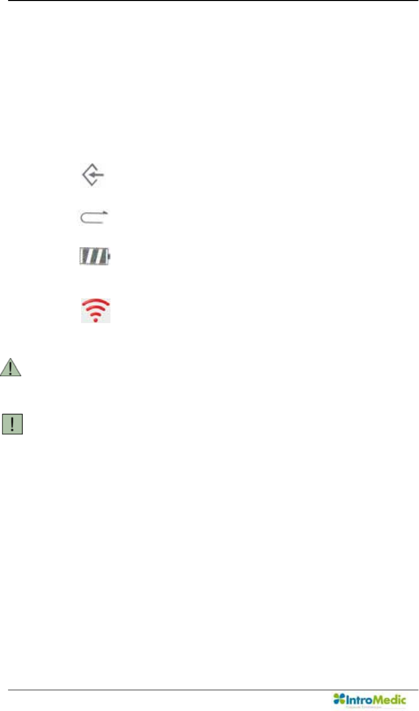
1.3.2 MiroCam® Receiver Function Symbols
Symbol Description
SIG
Indicates status of signal from the MiroCam® Capsule.
Green : Signal is being received from the MiroCam®
Capsule.
Yellow : Signal is not being received from the
MiroCam® Capsule.
INI
Initialization status of the MiroCam® Receiver
Green : MiroCam® Receiver is initialized
Yellow : MiroCam® Receiver is not initialized
BAT
Battery Status
Green : Fully charged
Yellow : Not charged
Wi-Fi
Wi-Fi Switch Status
(LED) On : Enabled
(LED) Off : Disabled

Chapter 1 Safety Information
1-11
1.4 Notes for Safe Use
Follow the safety instructions included in this User Manual and
clinical precautions advised by the medical professional.
The manufacturer is not liable for harm or damage caused by
improper, unauthorized, unprofessional or inexpert use of the device
and/or product.
IntroMedic Co., Ltd. is NOT responsible for physical harm or
HTXLSPHQW SUREOHPV FDXVHG E\ WKH XVHU¶V FDUHOHVV RSHUDWLRQ RU
mismanagement of the device and/or product.
Users MUST have read and understood the User Manual. ONLY
trained and qualified medical professionals or authorized
representatives of IntroMedic Co., Ltd. may operate the system.
User Manual must ALWAYS be with the equipment. This is the
86(5¶65(63216,%,/,7<.
CAUTION: foreign substances including water, cleaning fluids,
disinfecting cleanser and such substances may harm the equipment,
and should not enter the equipment.
ONLY authorized personnel may perform repairs. Never attempt to
open covers, panels or casings.
DO NOT crease, bend, fold or twist the data cable (or data belt). Take
care to guard them against mechanical stress (e.g. wheels or heels)!
The sensor pads, the MiroCam® Receiver, the data cable, the data
belt and the capsule must not be exposed to mechanical shock (e.g.
by dropping). Any damage caused that way will void the product
warranty.
CAUTION: Damage/injuries to the sensor pad, data cable or data belt
may cause a safety hazard. Damaged items MUST be repaired
IMMEDIATELY.
DO NOT handle fluids in the vicinity of the system.

Safety Information Chapter 1
1- 12
When using a cart purchased elsewhere, ensure the brake or latch
guard is in use to prevent the wheels from rolling.
DO NOT USE in moist or damp places.
DO NOT operate the equipment with wet hands.
Avoid using the equipment in extreme temperatures or humid
environments.
DO NOT keep the equipment or carry out the MiroCam® Capsule
endoscopy procedure in places such as areas exposed to direct
sunlight, vicinity of heaters, vicinity of chemical materials or gases,
areas moist/damp or dusty, or poorly ventilated areas.
DO NOT disassemble or open the equipment without permission.
This will invalidate the warranty.
DO NOT carry out the MiroCam® Capsule endoscopy procedure in
areas with high vibrations or in environments where high electro-
magnetic waves are generated.
DO NOT pull out the power cord by grabbing the cable. When
disconnecting the power cord, grasp the plug, and pull out. This
prevents short-circuits, disconnection, or cord damage.
CAUTION: Verify that the power rating supplied from the power
receptacle matches with the voltage the system requires. Check
Voltage and Frequency on the AC/DC adaptor.
CAUTION: Turn off the power switch before connecting the sensor
pad.
DO NOT discard sensor pads, cables and connectors with general
waste. Discard separately as industrial or medical waste.
DO NOT carry out the MiroCam® Capsule endoscopy procedure
simultaneously with other procedures using medical products or
equipment.
DO NOT use for purposes other than medical treatment.

Chapter 1 Safety Information
1-13
DO NOT connect the USB cable to the MiroCam® Receiver while the
MiroCam® Receiver¶Vdata cable is still connected to sensor pads or
data belt.
DO NOT charge the MiroCam® Receiver while the MiroCam®
5HFHLYHU¶V GDWD FDEOH LV VWLOO FRQQHFWHG WR VHQVRU SDGV RU GDWDEHOW
while still attached to the human body.
Connect USB cable to the MiroCam® Receiver only after mounting it
on charger.
DO NOT install any other programs onto the workstation utilized for
review and diagnosis of patient image data (i.e computers with the
0LUR9LHZ Software).
The MiroCam® Capsule is disposable and should not be reused.
The sensor pads and data belt are medical waste, and should be
disposed of according to local regulations or WEEE directive on
waste disposal.
Only use the capsule, the MiroCam® Receiver, the data cables, the
sensor pads and the data belt in the medical environment condition.
All products connected with the MiroCam® Endoscope system must
be compliant with requirements of IEC60950-1 or UL certifications.
Check the outer surface of the endoscope for rough surfaces, sharp
edges, or protrusions which may cause a safety hazard.
3OHDVHGRQ¶WWU\WRFXWWKHODEHO

Safety Information Chapter 1
1- 14
1.4.1 Environmental Conditions for Storage
Temperature : -10 ~ 70 (Operating 0 ~ 40 )
Relative humidity : 10 % ~ 80 % (Operating 45 % ~ 75 %)
Atmospheric pressure : 700hPa to 1060hPa
WARNING DO NOT operate the equipment in the vicinity of
generators, power stations, X-ray devices, and
broadcasting stations where high levels of electro-magnetic
waves are generated. The electro-magnetic waves can
cause equipment malfunctions.
CAUTION If the equipment has been brought in from a cold
environment (stock room, airfreight) into a warm room,
initial activation should take place after a few hours, to
allow for temperature adjustment and balance and
evaporation of condensed humidity.
WARNING DO NOT operate the equipment in the vicinity of heat
sources, strong electric or magnetic fields (close to a
transformer), or near instruments generating
high-frequency signals.
WARNING DO NOT use MiroCam® alongside or together with medical
devices or procedures involving electrical currents.
DO NOT use MiroCam® with h.f. surgical equipment. It
may result in burns at the site of the electrodes and
possible damage to the MiroCam® Capsule and the
MiroCam® Receiver.
DO NOT use the unit in close radius (within 1 m) of short
wave or microwave therapy equipment. It may produce
instability in the captured image.
WARNING This device is a Class B device according to EN60601-1-2
standards. This equipment can cause radio interference in
residential areas. In this case, the owner (or operator) can
be held responsible to take appropriate measures or take
proper measures for compensation.

Chapter 1 Safety Information
1-15
1.4.2 Safety Precaution
CAUTION - Make sure the environment is without interference from
electromagnetic fields.
- Make sure the environment is without noise and
vibration.
- DO NOT carry out the MiroCam® Capsule endoscopy
procedure while using other equipments, devices or
products.
- The instruction for use of the sensor pads MUST be
observed.
- DO NOT use on patients with pacemakers or
defibrillators.
- DO NOT use the MiroCam® Capsule if the package is
unsealed.
DO NOT reuse a used capsule.
To prevent unexpected accidents like fire or explosion, do not use any
product near or in the presence of inflammable or ignitable
substances.
DO NOT disassemble the equipment case nor open the cover. In
case service is required, please contact IntroMedic customer support
or local point of sale immediately.
Only the accessories authorized and designed by IntroMedic Co., Ltd.
should be used with this equipment. Faults resulting from the usage
of unapproved or inappropriate accessories are not guaranteed
against.
This equipment may affect on other products or be affected by other
products.
)ROORZ \RXU GRFWRU¶V LQVWUXFWLRQV DQG DELGH E\ WKH JXLGHOLQHV LQ WKH
User Manual.
DO NOT try to upload the image data while the data cable or data
belt is still connected to the MiroCam® Receiver.

Safety Information Chapter 1
1- 16
DO NOT change the rechargeable battery in the MiroCam® Receiver
while the data cable or data belt is still connected to the MiroCam®
Receiver.
Stay away from high frequency radiation sites (such as high voltage,
radar, installation power plants, MRI, CT or electric blankets etc.)
during your capsule endoscopy procedure. (It may result in serious
side effects requiring an emergency operation.)
In case of any symptoms of abdominal pain, vomiting, fever, heart
trouble, dizziness or seizure during or after the MiroCam® Capsule
endoscopy procedure, please notify your doctor.
Always check whether the data cable or data belt is connected to the
MiroCam® Receiver.
Always check that the battery in the MiroCam® Receiver is fully
charged before use.
DO NOT use the MiroCam® Capsule if the package is unsealed.
After ingesting the capsule, always confirm whether the MiroCam®
Capsule has been excreted. Excretion of the MiroCam® Capsule can
be confirmed with an X-ray procedure.
Prior to undergoing the MiroCam® Capsule endoscopy procedure,
patients with diabetes must be informed via a medical professional
regarding appropriate medication & dosage.
For more accurate data and better analysis, patients can have solid
food for lunch, but must have liquid food for dinner on the day prior to
the MiroCam® Capsule endoscopy procedure. The patient must fast
for 11 hours prior to ingesting the MiroCam® Capsule.
If recommended by the physician, the patient may take a laxative
prior to the MiroCam® Capsule endoscopy procedure.
DO NOT smoke for at least 12 hours prior to the MiroCam® Capsule
endoscopy procedure.

Chapter 1 Safety Information
1-17
DO NOT apply body lotion before the MiroCam® Capsule endoscopy
procedure.
DO NOT bite the capsule.
Avoid excessive physical activity during the MiroCam® Capsule
endoscopy procedure.
4 hours after ingesting the capsule, patients may have liquid food.
It is recommended to drink mineral water (non-colored liquid)
frequently, so that it may raise the possibility to take much better
quality of the image.
When undergoing the MiroCam® Capsule endoscopy procedure, DO
NOT make physical contact with another person undergoing the
same procedure.
During the MiroCam® Capsule endoscopy procedure, DO NOT touch
the MiroCam® Receiver, or get the MiroCam® Receiver wet.
Only use the provided batteries, and never remove the battery from
the MiroCam® Receiver during the MiroCam® Capsule endoscopy
procedure.
Avoid disconnecting the USB while uploading the image data from the
MiroCam® Receiver to the workstation.
Always confirm that the USB is connected by checking the MiroCam®
Receiver screen on the 0LUR9LHZ Software.
Always check the AC Power rating prior to using the workstation.
DO NOT touch AC power cable with wet hands.
DO NOT open the MiroCam® Receiver bag or touch the MiroCam®
Receiver outside of the hospital.
DO NOT use on patient with electrical implantable device.
Magnetic controller must be stored in special storage box.
If electrical risk is detected from the MiroCam® Receiver, remove the
battery.

Safety Information Chapter 1
1- 18
WARNING The MiroCam® Capsule takes images for 12 hours and
naturally excretes in about 24 hours under normal
conditions. If the MiroCam® Capsule has not been
excreted from the patient within 72 hours, patient should
contact the physician. After examining, the physician may
need to perform a surgical operation or treatment to
remove the capsule.
WARNING Before doing capsule endoscopy with MC1000-WM, always
check whether the previous capsule is retained or not in
human body. If the previous capsule is detected in human
body, remove it by surgical treatment. When two
MC1000-WM are existed in human body at the same time,
those can stick to each other.
WARNING Make sure the capsule had been excreted before going
through an MRI, CT and etc. It may cause injury to the
patient.

Chapter 1 Safety Information
1-19
1.4.3 Cleaning and Maintenance
Capsule
The capsule is disposable and should not be reused.
System and accessories
- All products should be cleanly maintained. For cleaning, rub them
lightly with a soft cloth wet with warm water at least once a week.
DO NOT use organic solvents such as lacquer, thinner, ethylene
and oxide because they can damage the equipment. Be careful
that foreign substances do not enter the main system when
cleaning.
- ALWAYS operate the equipment under sanitary environmental
conditions. DO NOT use heat or gas for disinfection of the capsule.
Service Document
If required, or upon request, the local IntroMedic distributor
(authorized IntroMedic representative) may provide block diagrams,
lists of spare parts, descriptions, adjustment instructions or other
related information which may help qualified technical personnel in
repairing specified parts of the equipment which have been defined
repairable by IntroMedic Co., Ltd. .
Moving the Equipment
- CAUTION when moving equipment.
- WARNING: Excessive impact/shock causes internal damage.
- If wiring is connected/disconnected when moving, check the exact
wiring status after moving.
- If damage to the equipment is discovered after moving,
immediately contact IntroMedic or local Distributor.

Safety Information Chapter 1
1- 20

2
Overview & Intended Usage

Overview & Intended Usage Chapter 2
2- 2

Chapter 2 Overview & Intended Usage
2-3
2. SYSTEM OVERVIEW
MiroCam® is an orally ingested capsule endoscope designed to capture
and wirelessly transmit images of the lining of the small intestine.
Captured images are viewed via the 0LUR9LHZ6RIWZDUH for diagnosis
of diseases related to the small intestine.
The MiroCam® Capsule Endoscope System consists of the MiroCam®
Capsule, the MiroCam® Receiver, the 0LUR9LHZ 6RIWZDUH, and
accessories.
2.1 Intended Purpose
MiroCam® is intended for visualization of the small bowel mucosa as an
adjunctive tool in the detection of abnormalities of the small bowel. The
device captures images of the small bowel with a wireless camera
contained in a capsule. This device includes an ingestible capsule
(containing a light source, camera, transmitter, and battery), an
electrode array, a receiving/recording unit, a data storage device,
computer software to process the images (0LUR9LHZ Software), and
accessories.

Overview & Intended Usage Chapter 2
2- 4
2.1.1 Contraindications
Not intended for patients with known or suspected gastrointestinal
tract obstructions, perforations, strictures or fistular.
Not intended for patients who have difficulty ingesting food or pills
(dysphagia).
Not intended for patients who have difficulty communicating.
Not intended for patients with indigestion, or slow gastric emptying.
Not intended for patients who may be affected by electromagnetic
radiation, such as pregnant women, infants, and patients with
heart disease or epilepsy.
Not intended for patients with diverticulosis in the Small Bowel.
Not intended for patients who are recommended against having
the MiroCam® Capsule endoscopy procedure by a Physician.
Not intended for patients with pacemakers and/or defibrillators.
This device is intended for use in adults and children from two
years of age. If a patient is younger than 18, the doctor should
decide whether to perform the MiroCam® Capsule endoscopy
procedure.
2.2 Observable Diseases
2.2.1 Obscure gastrointestinal bleeding (OGIB)
Angioectasia
Meckel diverticulum
NSAIDs
2.2.2 &URKQ¶V'LVHDVH

Chapter 2 Overview & Intended Usage
2-5
2.2.3 Small Bowel Tumors
Polyps
Peutz-Jeghers Syndrome
Familial adenomatous polyposis
Lymphoma
Carcinoid
Gastro-Intestinal Stromal Tumor (GIST)
Lipoma
Hemangioma
2.2.4 Inflammation
Intestinal Tuberculosis
Typhoid Fever
Angeitis
Amyloidosis
Eosinophilic enteritis
2.2.5 Celiac Disease
2.2.6 %HKFHW¶V'LVHDVH
2.2.7 Cowden Disease
2.2.8 Cronkhite-Canada Syndrom

Overview & Intended Usage Chapter 2
2- 6
2.3 Product Warranty Period
2.3.1 Maximum Storage Time of MiroCam® Capsule
MC1000 : 1 Year
MC1000-F : 1 Year
MC1000-G : 1 Year
MC1000-W : 1 Year
MC1000-WG : 1 Year
MC1000-WM : 1 Year
MC1000-B : 1 Year
MC1200 : 1 Year
MC1200-B : 1 Year
MC1200-G : 1 Year
MC1200-M : 1 Year
MC1600 : 1 Year
MC1600-B : 1 Year
MC1600-G : 1 Year
MC1600-M : 1 Year
2.3.2 MiroCam® Receiver, MR1100
MiroCam® Receiver:1 Year
MiroCam® Receiver Battery: 6 Months

Chapter 2 Overview & Intended Usage
2-7
2.4 Product Specification
2.4.1 MiroCam® Capsule
Component
Component Model Name Quantity
Capsule MC1000
MC1000-F
MC1000-G
MC1000-W
MC1000-WG
MC1000-WM
MC1000-B
MC1200
MC1200-B
MC1200-G
MC1200-M
MC1600
MC1600-B
MC1600-G
MC1600-M
1 Piece (Selection)
Sensor Pads MC1000-S 10 Piece
Magnetic
Controller
MC1000-C 1 Piece (Optional)

Overview & Intended Usage Chapter 2
2- 8
Specification
Item Specification
Capsule Unit
(MC1000,
MC1000-F,
MC1000-G)
Size 10.8 X 24 mm
Weight 3.25 ± 0.05 g (-F)
3.5 ± 0.05 g
Frame Rate 3 frame/sec
Field of View 150 degrees
Battery Life 12 hours
Pixels 102,400
Lighting 6 LEDs
Communication
Method
Human Body
Communication
Magnetic
Controller
(MC1000-C)
Length 27.3 cm

Chapter 2 Overview & Intended Usage
2-9
Item Specification
Capsule Unit
(MC1000-W,
MC1000-WG,
MC1000-WM,
MC1000-B)
Size 10.8 X 24.5 mm
10.8 X 25.5 mm (-WM)
Weight 3.25 ± 0.05g
4.75 ± 0.05g (-WM)
Frame Rate 3 frame/sec
Field of View 170 degrees
Battery Life 12 hours
8 hours (-WM)
Pixels 102,400
Lighting 6 LEDs
Communication
Method
Human Body
Communication

Overview & Intended Usage Chapter 2
2- 10
Item Specification
Capsule Unit
(MC1200
MC1200-B
MC1200-G,
MC1200-M)
Size 10.8 X 24.5 mm
Weight 3.2 ± 0.05 g
4.5 ± 0.05 g (-M)
Frame Rate 3 frame/sec
Field of View 170 degrees
Battery Life 12 hours
8 hours (-M)
Pixels 102,400
Lighting 6 LEDs
Communication
Method
Human Body
Communication

Chapter 2 Overview & Intended Usage
2-11
Item Specification
Capsule Unit
(MC1600
MC1600-B
MC1600-G,
MC1600-M)
Size 10.8 X 24.5 mm
Weight 3.2 ± 0.05 g
4.5 ± 0.05 g (-M)
Frame Rate 6 frame/sec
Field of View 170 degrees
Battery Life 12 hours
8 hours (-M)
Pixels 102,400
Lighting 6 LEDs
Communication
Method
Human Body
Communication

Overview & Intended Usage Chapter 2
2- 12
2.4.2 MiroCam® Receiver
Component
Component Model Name Quantity
Receiver MR1100 1 piece
Battery Pack MR1100-B 2 piece
Data Cable MR1000-D 1 piece
Data Belt MR1000-D(M),
MR1000-D(L)
1 piece
Receiver Bag MR1000-G 1 piece
System Carrying Case MR1000-A 1 piece
Battery Charger MR1000-C 1 piece
Adaptor MR1000-T 1 piece
Power Cable MR1000-P 1 piece
Measuring Tape MR1000-M 1 piece
USB Cable MR1100-U 1 piece
Specification
Item Specification
Receiver
(MR1100)
Battery Life 12 Hours
Size 85 X 140 X 40 mm
Weight 350g (including Battery)

Chapter 2 Overview & Intended Usage
2-13
Item Specification
Battery Pack
(MR1100-B)
Type Lithium-Ion storage cell
Capacity 10400 mA
Voltage 3.6 V
Recharging Time Approx. 4 hours
Size 73.8 X 84.3 X 21.4 mm
Data Cable
(MR1000-D)
Channel 9
Size 700 x 900 x 110 mm
Data Belt
(MR1000-D(M),
MR1000-D(L))
Channel 9
Size 1000 X 180 mm (M)
1500 X 180 mm (L)
Receiver Bag
(MR1000-G)
Size 100 X 190 X 55 mm
System Carrying
Case(MR1000-A)
Size 480 X 350 X 100 mm
Battery Charger
(MR1000-C)
Power Source Adaptor
Size 135 X 75 X 105 mm
Weight 285 g
Adaptor
(MR1000-T)
Weight 231g
Power Rating AC100~240V/ 50~60
Hz

Overview & Intended Usage Chapter 2
2- 14
Item Specification
Power Cable
(MR1000-P)
Length 1.5 m
Measuring Tape
(MR1000-M)
Length 1.5 m
2.4.3 MiroCam® Software
Component
Component Model Name Version
0LUR9LHZ:RUNVWDWLRQ 0LUR9LHZ Software 2.5
0LUR9LHZ579 0LUR9LHZ579 2.0
Wireless MiroView RTVi Wireless MiroView
RTVi
1.4

3
Performing Capsule Endoscopy

Performing Capsule Endoscopy Chapter 3
3- 2

Chapter 3 Performing Capsule Endoscopy
3-3
3. PERFORMING CAPSULE ENDOSCOPY
3.1 General Comments
This chapter describes how to operate and control the MiroCam®
Capsule Endoscope System.
Installation and initial operation must be done by an Authorized
IntroMedic Service Technician.
3.2 Safety Warnings
WARNING Before turning on the system, check the environment
condition for the MiroCam® Capsule Endoscope System.
WARNING This device is intended for use in adults and children from
two years of age. If a patient is younger than 18, the doctor
should decide whether to perform the MiroCam® Capsule
endoscopy procedure.
CAUTION In case the system has been brought from cold
environment (stock room or airfreight) into a warm room,
first switch on it after some hours for temperature balance
and removing of condensation humidity (Risk of leakage
current).
CAUTION For the electrical safety, make sure that peripheral
equipments (external PC, Monitor, printer etc) are
connected to a wall socket of independent power supply
with a perfect ground. Particularly make sure whether or not
those peripheral equipments should be authorized for
medical usage.
CAUTION DO NOT touch the dome of the capsule.
CAUTION If SIG indicator of the MiroCam® Receiver turns yellow
after ingesting the capsule, immediately contact the
physician.
Performing Capsule Endoscopy Chapter 3
3- 4
CAUTION If SIG indictor of the MiroCam® Receiver does not turn
green when the patient holds the MiroCam® Capsule by
the gold bands, immediately stop the MiroCam® Capsule
endoscopy procedure.
NOTE If images of the small bowel are not captured during the
MiroCam® Capsule endoscopy procedure, ensure the
MiroCam® Capsule has been excreted by the patient and
perform procedure again.
3.3 Examination Preparation
The following steps (3.3.1 to 3.3.4) explain the process to initialize the
MiroCam® Receiver and register patient data for the MiroCam® Capsule
endoscopy procedure. For more information, see section 4.2.
3.3.1 Start System
Turn on the power of the workstation.
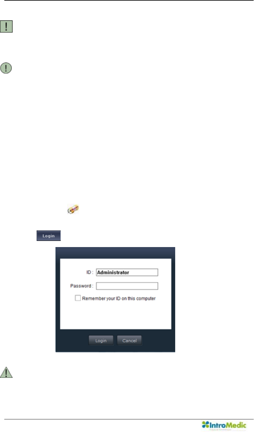
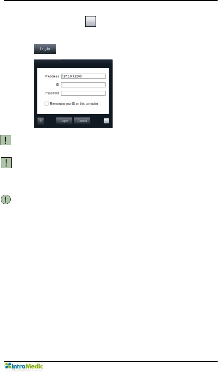
Click the to start the 0LUR9LHZOperator.
Type the ID and the password in each field, and then click the
.
WARNING Before starting the system, check the power rating for the
workstation.
Chapter 3 Performing Capsule Endoscopy
3-5
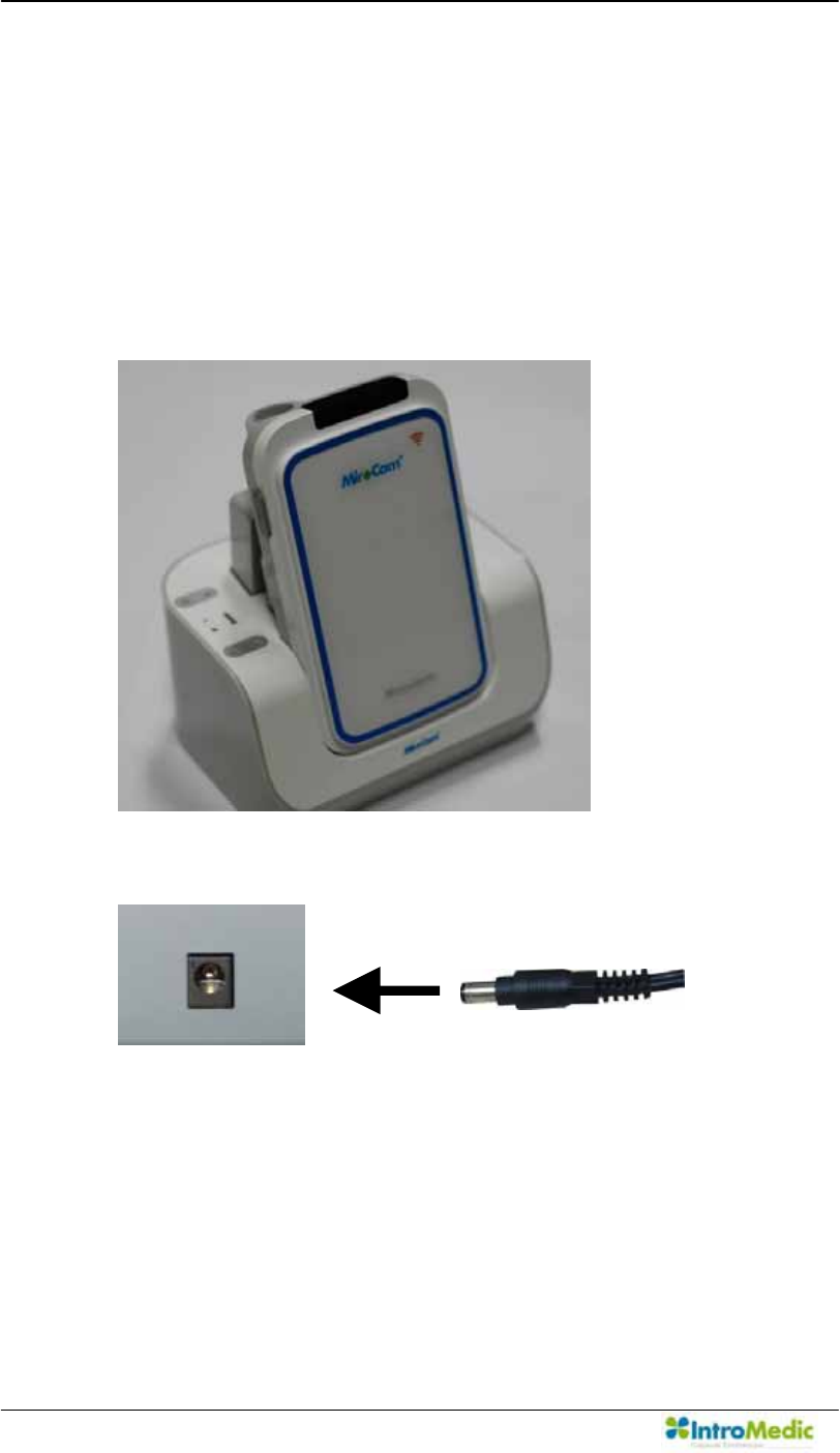
3.3.2 Initialize the MiroCam® Receiver
Connect the smaller side of the USB Cable to the MiroCam®
Receiver
Connect the larger side of the USB cable to the workstation.
Turn on the MiroCam® Receiver.
Click the in the 0LUR9LHZ Operator to initialize the
MiroCam® Receiver.
Click the in the 0LUR9LHZ Operator to input patient
information.
After completing the required fields, click the to save the
patient information onto the MiroCam® Receiver.
WARNING If the MiroCam® Receiver is initialized, any patient data
stored on the device will be deleted permanently.
NOTE During initialization with MR1100, it is not possible to cancel
the process.
3.3.3 MiroCam® Receiver Preparation
Connect the battery to the MiroCam® Receiver.
- Insert pins and bumps on back side of the MiroCam®
Receiver in the slots on the battery.
- Press battery to the MiroCam® Receiver until clasp locks
battery in place.
Turn on the power switch of the MiroCam® Receiver.
Check the battery indicator (BAT) of upper side of the MiroCam®
Receiver. If the battery is fully charged, the LED light will be
green. If the LED light is not green, charge the battery.
Performing Capsule Endoscopy Chapter 3
3- 6
Check the initialization indicator (INI) of upper side of the
MiroCam® Receiver. Prior to beginning a procedure, this light
must be green.
Connect the data cable to the MiroCam® Receiver.
Indicator Description
SIG Indicates status of signal from capsule
Green : Signal is being received from capsule
Yellow : Signal is not being received from capsule
INI Initialization status of the MiroCam® Receiver
Green : The MiroCam® Receiver is initialized
Yellow : The MiroCam® Receiver is not initialized
BAT
Battery Status
Green : Fully charged
Yellow : Not charged
Wi-Fi
Wi-Fi Switch Status
(LED) On : Enabled
(LED) Off : Disabled
WARNING DO NOT do begin the MiroCam® Capsule endoscopy
procedure when the MiroCam® Receiver¶VEDWWHU\LQGLFDWRU
is not green. This indicates battery is not fully charged or
out of order, and patient data may be lost.
CAUTION Switch the MiroCam® Receiver off prior to connect the
sensor pad.

Chapter 3 Performing Capsule Endoscopy
3-7
3.4 Patient Preparation
Provide the patient with the following instructions to prepare for the
MiroCam® Capsule endoscopy procedure.
3.4.1 Patient Preparation
One day prior to the MiroCam® Capsule endoscopy procedure
- Lunch: Patient can have a normal mean around noon,
followed by a liquid diet as instructed by the physician.
- The patient should fast for at least 12 hours prior to the
MiroCam® Capsule endoscopy procedure. Patient may only
drink water (no food or other beverages such as milk or
coffee).
- The patient should not take any medications two hours before
ingesting the MiroCam® Capsule endoscope.
- Male patients may need to shave area, as advised by
physician or nurse.
- Patient should stop taking iron supplements 1 week before
the MiroCam® Capsule endoscopy procedure, and should
not ingest any medicine at least 2 hours prior to the
MiroCam® Capsule endoscopy procedure.
- Diabetic patients need to follow any changes to insulin
dosage as prescribed by the physician.
- Physician is recommended to prescribe patient a laxative
such as PEG or Sodium Phosphate. Patient should ingest
laxative 12 hours prior to procedure.

Performing Capsule Endoscopy Chapter 3
3- 8
- Physician is recommended to prescribe patient an anti-
foaming agent (such as simethicone), to reduce bubbles in
the GI tract. This should be ingested after the laxative.
- The patient should abstain from smoking 12 hours before the
MiroCam® Capsule endoscopy procedure.
- On the day of the MiroCam® Capsule endoscope test, the
patient should wear comfortable and loose cloths. One-piece
clothing should not be worn.
- Prior to the MiroCam® Capsule endoscopy procedure, do not
apply any lotions or perfumes.
On the day of capsule endoscopy procedure
- After arriving in a hospital at the appointed time, the patient
should submit an examination permission form and check in.
After ingesting capsule endoscope
- The patient should refrain from ingesting any food or drink
(except water) two hours after swallowing the MiroCam®
Capsule endoscope.
- Patient is recommended to drink water every half hour during
the MiroCam® Capsule endoscopy procedure.
- The patient can start with light food after 4 hours. When the
examination is complete, the patient can start having normal
meals.
- In case of any abdominal pain, nausea or vomiting after
ingesting the MiroCam® capsule, the patient should contact
physician or nurse immediately.
Chapter 3 Performing Capsule Endoscopy
3-9
3.5 Sensor Placement & Capsule Ingestion
Following is the detailed procedure required to correctly administer the
MiroCam® Capsule endoscopy procedure.
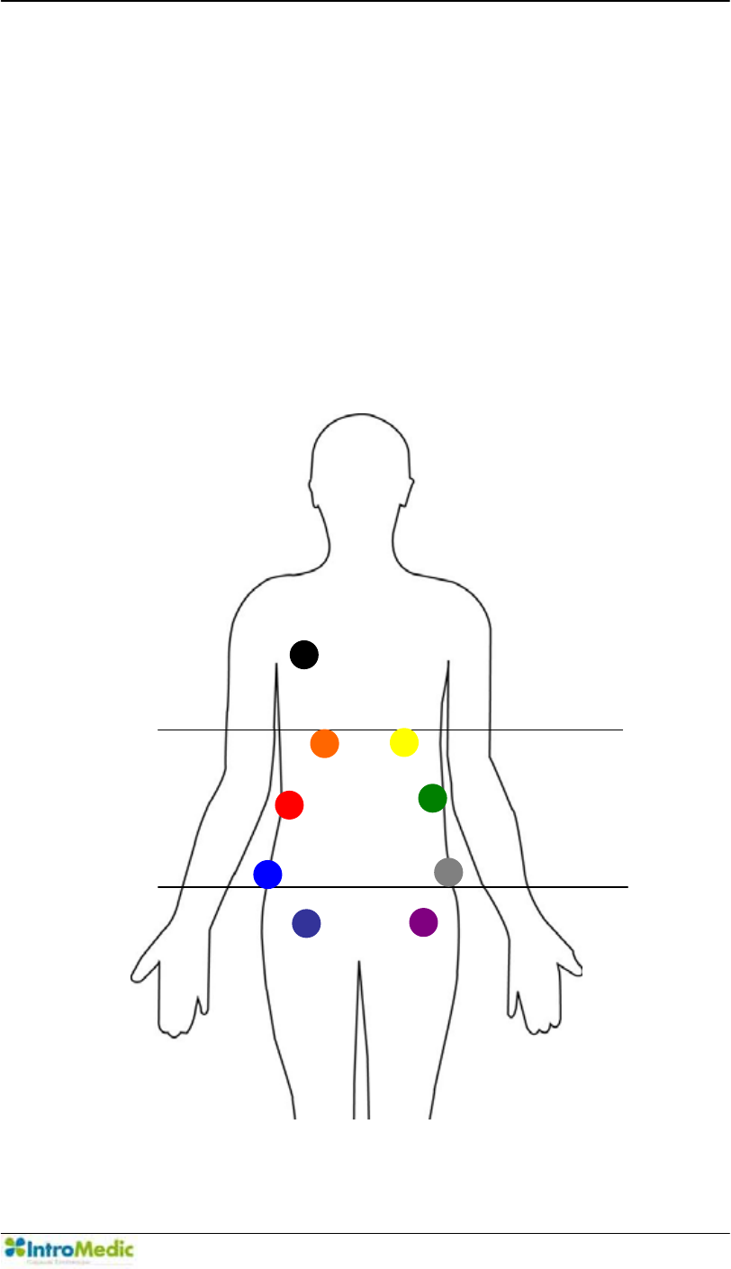
3.5.1 Connecting Sensor Pads
After attaching sensor pads to the data cables, attach the sensor
pad correctly to each area as shown below.
Xiphoid
process Line
Pelvic Line
1
4
6
7
8
5
R
2
3
Performing Capsule Endoscopy Chapter 3
3- 10
3.5.2
Attach sensor pads according to the number on the data cable.
-
Locate the center between the umbilical and the xiphoid
process. From this center point, attach the sensor to the distal
SRLQWRQWKHULJKWIODQNRIWKHSDWLHQW¶VERG\
-
Place the sensor pad on the xiphoid process line, directly
below the right clavicle.
-
Place the sensor pad on the xiphoid process line, directly
below the left clavicle.
-
Locate the center between the umbilical and the xiphoid
process. From this center point, attach the sensor to the distal
SRLQWRQWKHOHIWIODQNRIWKHSDWLHQW¶VERG\
-
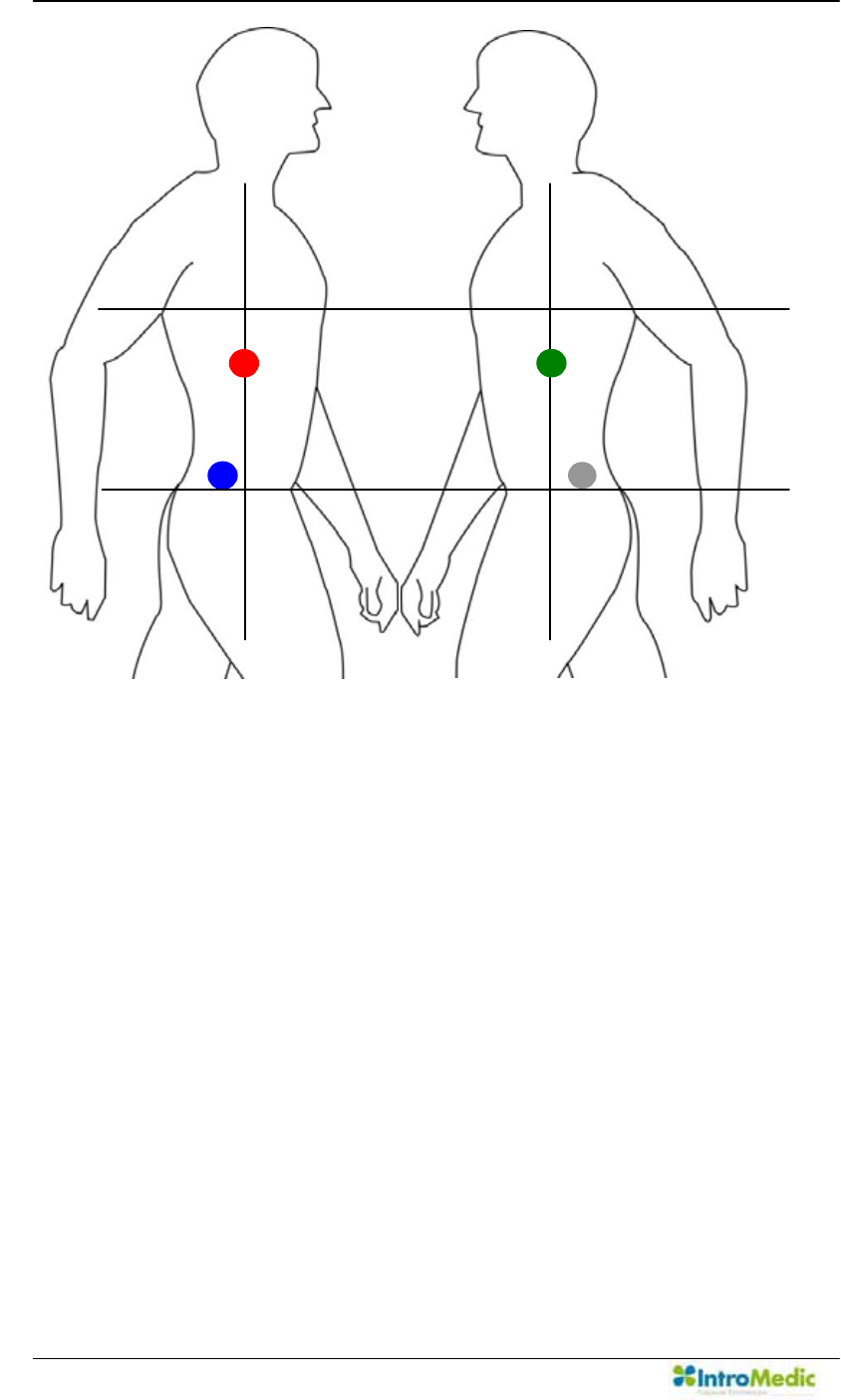
Place the sensor pad on the right pelvic line, 2 cm behind
sensor #1.
5 8 Pelvic
Line
Xiphoid
process Line
1 4
Chapter 3 Performing Capsule Endoscopy
3-11
-
Place the sensor on the right inguinal line, 2 cm to the outside
of sensor #2.
-
Place the sensor on the right inguinal line, 2 cm to the outside
of sensor #3.
- Place the sensor pad on the right pelvic line, 2 cm behind
sensor #4.
- Place the sensor directly below the right clavicle.
CAUTION The numbering of the data cables and sensor pad must
match the specified area. Please follow the numbering
sequence appropriately.
CAUTION To prevent entanglement of the data cables during
procedure, organize cables and place appropriately in cable
bag.
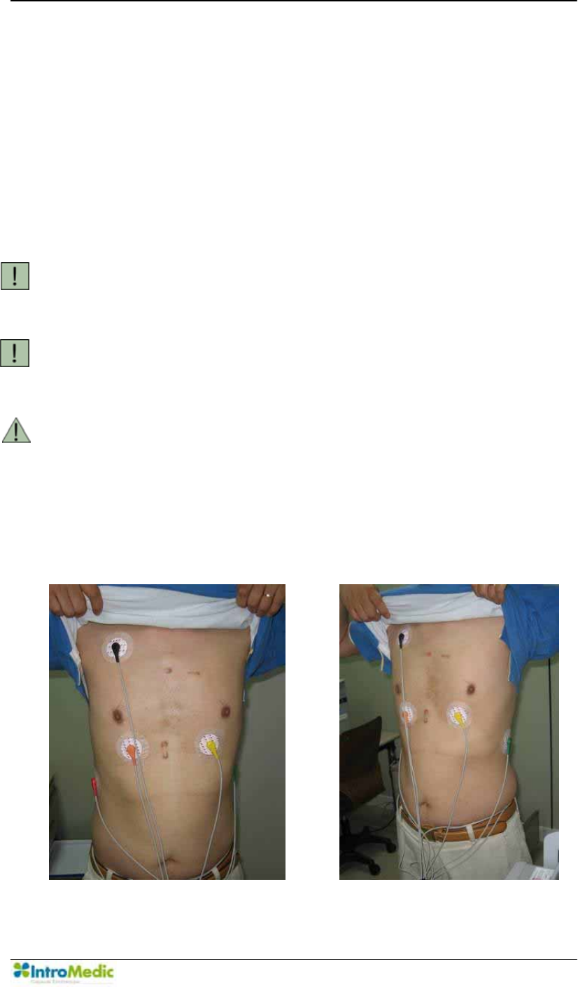
WARNING Correct image signal may not be obtained if a sensor pad is
not in direct, immediate contact with the skin. Ensure the
sensor pads are in direct contact with the skin. Shaving
may be required for male patients.
The pictures below show the sensor pads attached in the correct
locations.
Performing Capsule Endoscopy Chapter 3
3- 12
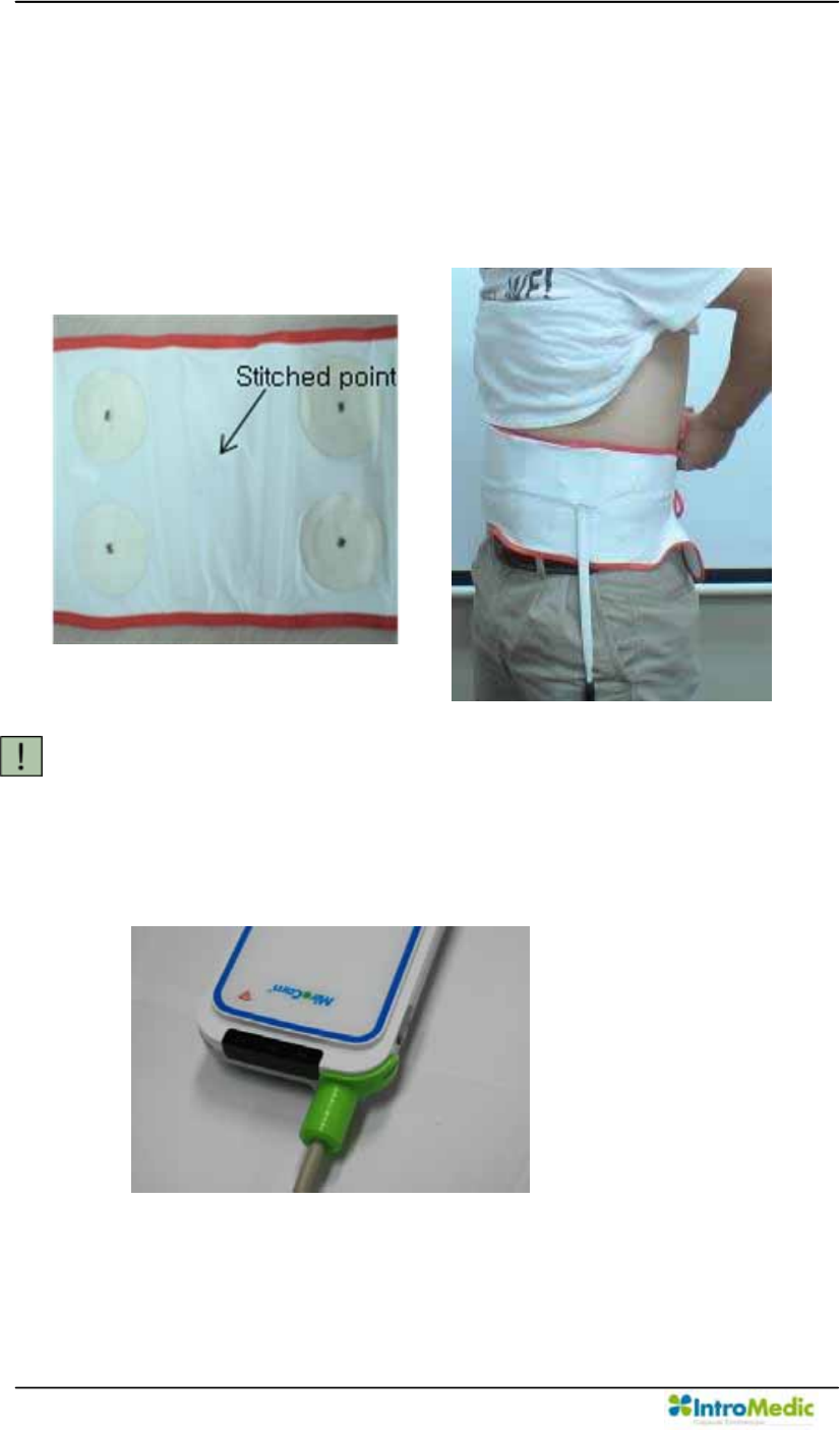
3.5.3 Connecting Data Belt
Attach stitched point on the belly button.
Tighten the data belt around the waist with the velcro.
Use the data belt as shown below.
After placing sensor pads on the patient, connect the cable to the
MiroCam® Receiver as detailed in the following image.
CAUTION Do not attached the Data belt above clothing
Chapter 3 Performing Capsule Endoscopy
3-13
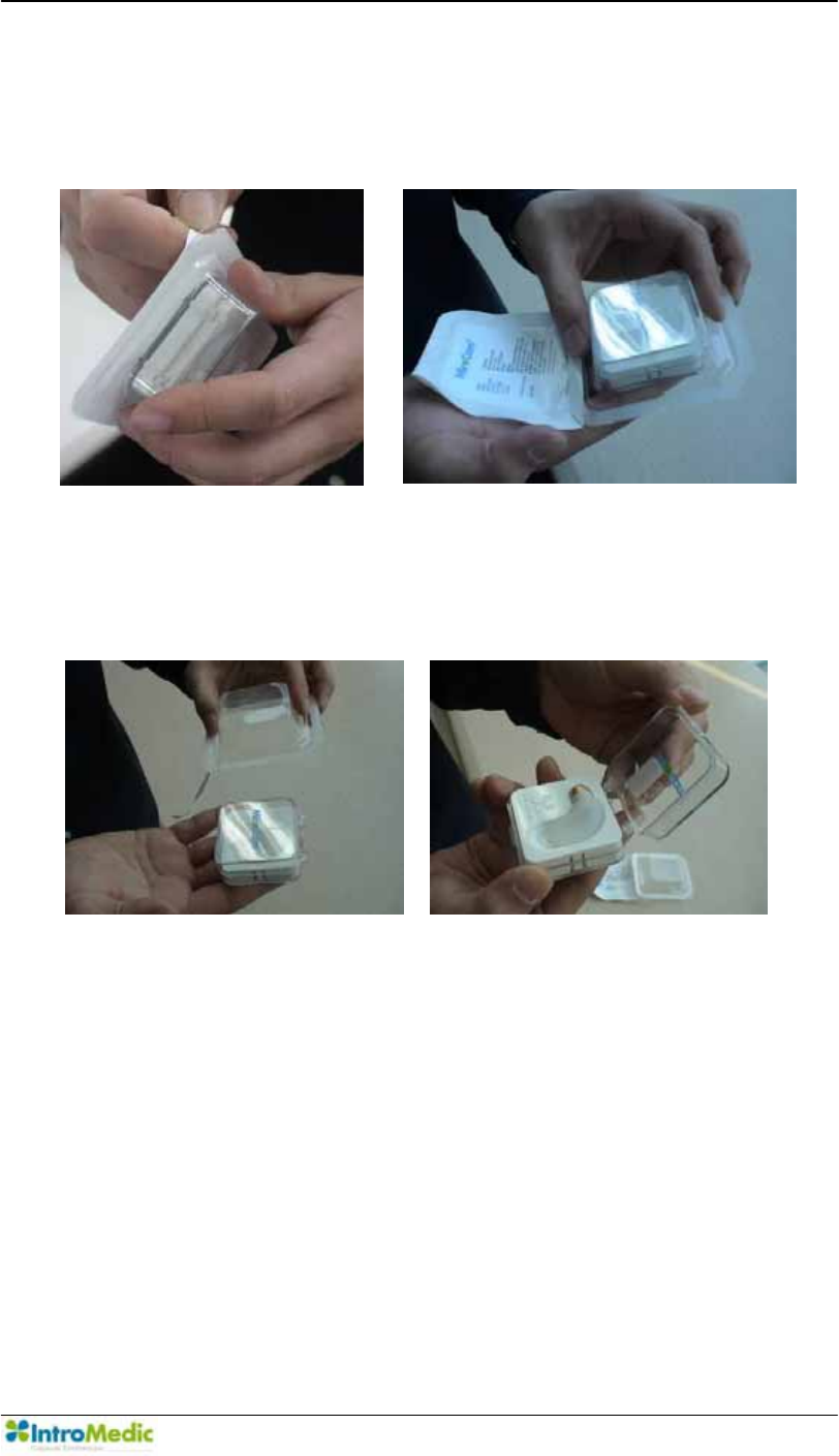
3.5.4 Removing Capsule from Package
While holding the case upside down, peel off the sterilized package
cover.
3.5.5 Removing the Case
Turn the package over, the MiroCam® case will slip out of the package.
While holding the case, open the lid.
Performing Capsule Endoscopy Chapter 3
3- 14
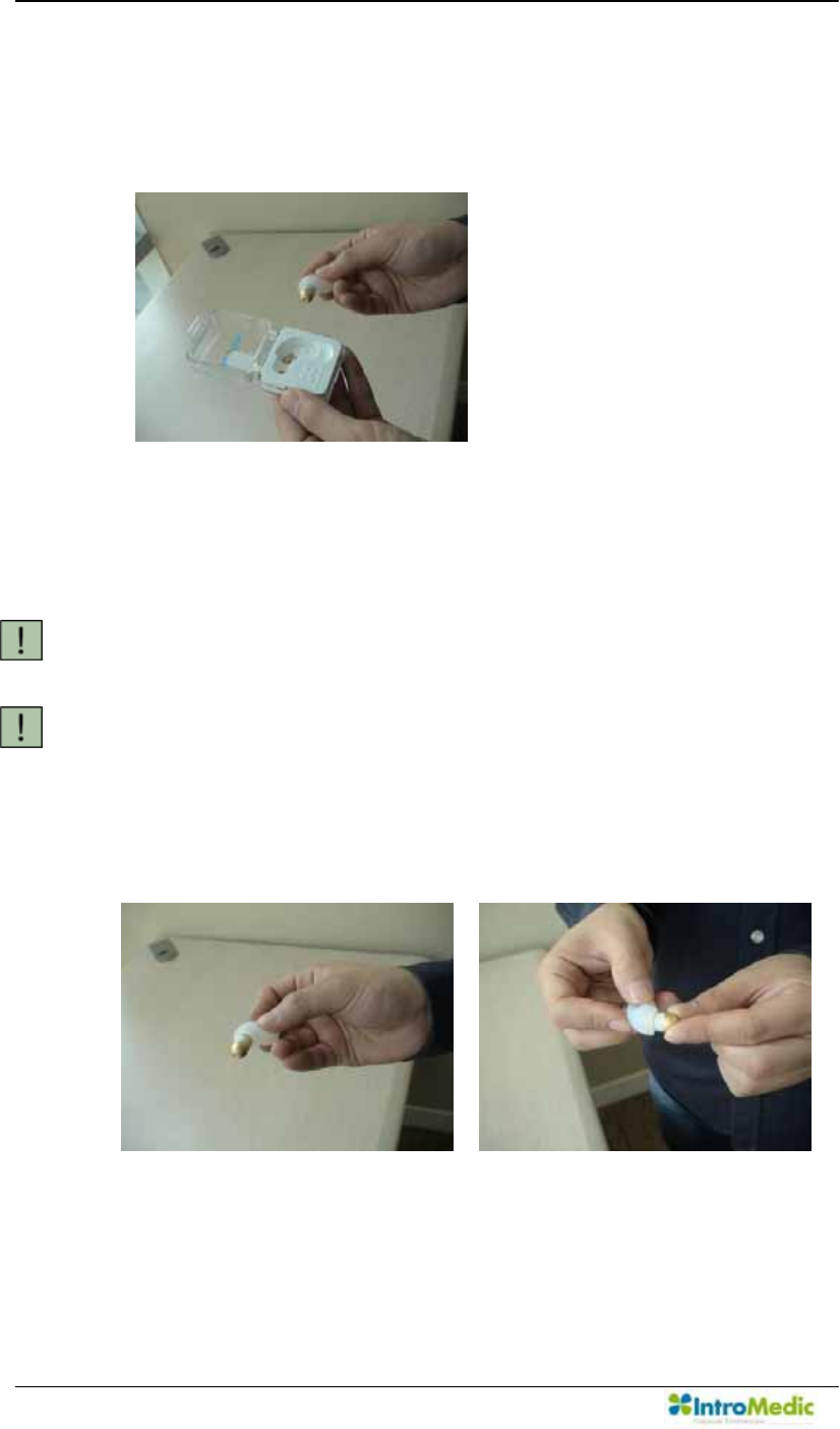
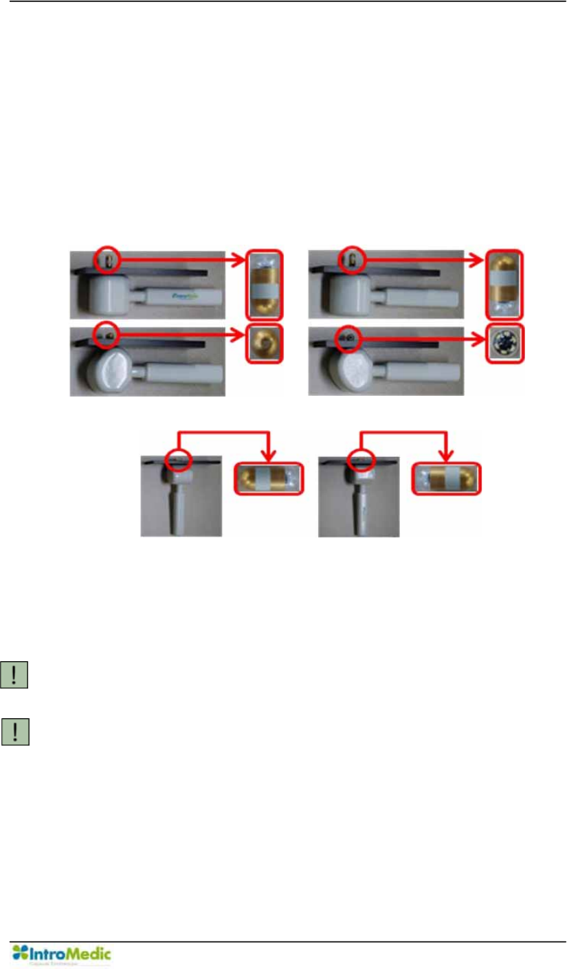
3.5.6 Removing the Capsule
Grip capsule with right hand, and remove from cast. DO NOT
touch the dome of the capsule.
Make sure that the MiroCam® Capsule packaging is not
damaged in any way. When removed capsule from case, the
MiroCam® Capsule should be flashing.
CAUTION Do not use a MiroCam® Capsule Endoscope if the
packaging or the MiroCam® Capsule is damaged.
CAUTION Do not touch the dome of the MiroCam® Capsule. This may
result in poor image quality.
Check if the front of the MiroCam® Capsule is flashing when it is
removed from the case
Chapter 3 Performing Capsule Endoscopy
3-15
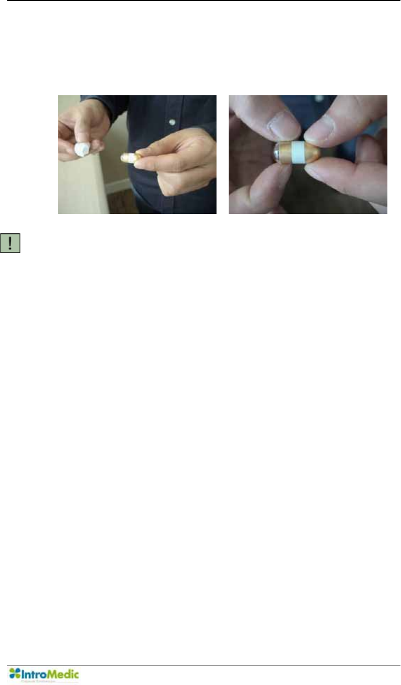
After washing hands, patients should grip the gold section of the
MiroCam® Capsule between the thumb and the forefinger of the
both hands.
CAUTION Initialize the MiroCam® Receiver prior to the MiroCam®
Capsule Endoscopy Procedure. Once the MiroCam®
Receiver confirms signal transmissions with a green SIG
indicator, the receiver will start recording for 12 hours, even
while the power switch of the MiroCam® Receiver is in the
off position.
3.5.7 Checking Operation of the MiroCam® Receiver and Signal
Reception
After the patient holds the MiroCam® Capsule as detailed above,
the signal indicator on the MiroCam® Receiver is green and signal
indication melody is generated. If signal indicator is yellow, there is
no signal being received from the capsule.
Switch on the MiroCam® Receiver.
Check if the battery indicator (BAT) at the top of the MiroCam®
Receiver shows that the battery is fully charged. The battery
indicator on the MiroCam® Receiver should be green.
Check if the initialize indicator (INI) at the top of the MiroCam®
Receiver shows that initialization is complete. The INI indicator on
the MiroCam® Receiver should be green.
Performing Capsule Endoscopy Chapter 3
3- 16
Connect the data cable to the MiroCam® Receiver.
After patient grasps capsule by opposing gold bands (as detailed
in picture above, check the SIG indicator on the MiroCam®
Receiver is green and signal indication melody is generate.
CAUTION If the battery indicator on the MiroCam® Receiver shows
that the battery is not fully charged, do not start the
endoscopy procedure. The battery may be depleted during
the MiroCam® Capsule endoscopy procedure and images
may not be saved properly.
CAUTION Please be noticed to confirm the shape and the direction of
the connector when you connecting the data cable to the
MiroCam® Receiver, since it may cause cable damage
problem.
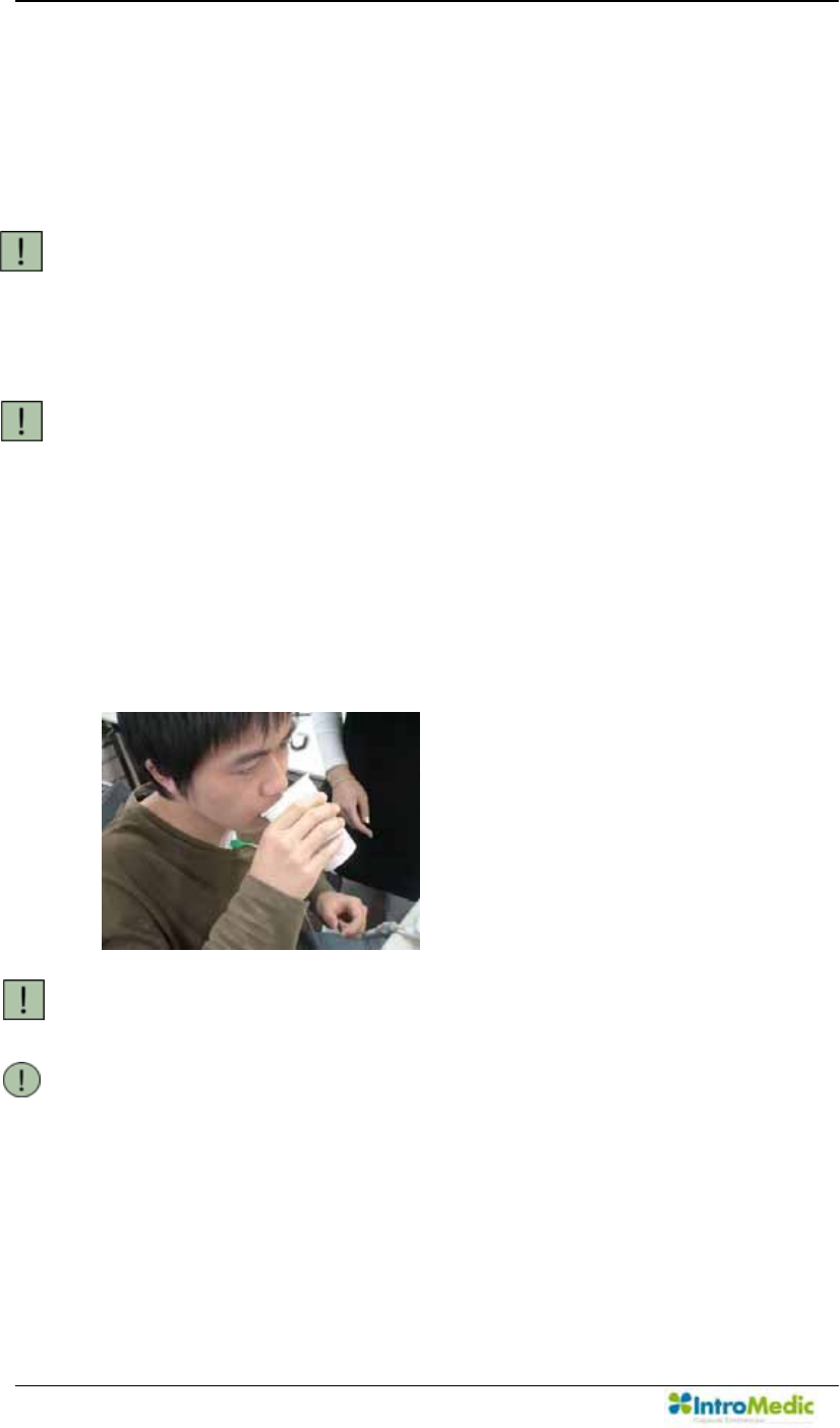
3.5.8 Ingesting the Capsule
After checking if the signal indicator on the MiroCam® Receiver is
green, ingest the MiroCam® Capsule with water.
CAUTION DO NOT bite the MiroCam® Capsule while ingesting.
NOTE To increase the effectiveness of the MiroCam® Capsule
endoscopy procedure, please be sure to drink water on a
regular basis.
Chapter 3 Performing Capsule Endoscopy
3-17
WARNING The MiroCam® Capsule should enter the stomach. Make
sure to always check that the MiroCam® Capsule enter the
stomach by checking the images on the MiroView RTV
(or the Wireless MiroView RTVi) and color of SIG
indicator on the MiroCam® Receiver turns green right after
ingesting the capsule.
WARNING DO NOT USE a MiroCam® Capsule that has been dropped
or coughed up by a patient. New MiroCam® Capsule
must be used. Take note of the new MiroCam® Capsule
number. The MiroCam® Receiver does not need to be
initialized again prior to swallowing the MiroCam® Capsule.
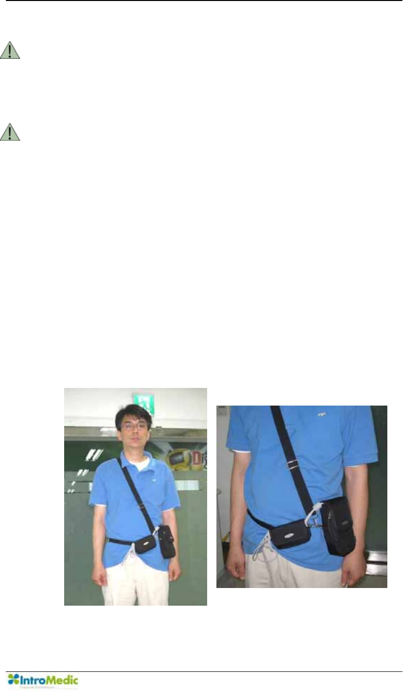
3.5.9 Checking and Wearing the MiroCam® Receiver
After ingesting the capsule, make sure that the SIG indicator is
green.
Place the MiroCam® Receiver in the bag.
Organize the contents of the bag so that the cables are not
entangled.
Adjust cables, and place excess in cable bag.
Adjust the bag strap as needed.

Performing Capsule Endoscopy Chapter 3
3- 18
The MiroCam® Capsule endoscopy procedure will be complete
after 12 hours.
CAUTION Patient should not touch the MiroCam® Receiver during the
MiroCam® Capsule endoscopy procedure. This may lead to
loss of image data.
CAUTION During the MiroCam® Capsule endoscopy procedure the
SIG indicator should be green.
In this case, check data cable to ensure it is securely
inserted and check the sensor pads to ensure these are
fixed to the body.
3.5.10 During the Procedure
After ingesting the MiroCam® Capsule Endoscope instruct the
patient to:
- Immediately report any episodes of abdominal pain,
nausea or vomiting, to the Nurse or Physician in charge.
- After ingesting the MiroCam® Capsule you may ingest
water, and only water. At least 250ml of water should be
ingested per hour.
- Four hours after swallowing the MiroCam® Capsule, you
will be permitted to resume a clear liquid diet. A clear
liquid diet includes water, clear broth, Jell-O, Sprite,
apple juice, and popsicles. No solid foods, milk or milk
products, or dark-colored liquids are allowed. A light diet
(e.g. applesauce, cereal, toast) can be resumed six
hours after the MiroCam® Capsule was swallowed.
- Do not touch or disturb the MiroCam® Receiver or get
them wet for the duration of the procedure. The
MiroCam® Receiver and sensors must remain on the
body for a period of 12 hours after ingestion of the
MiroCam® Capsule.

Chapter 3 Performing Capsule Endoscopy
3-19
- If a sensor pad or cable is removed during the
procedure, the patient can replace the sensor pad or
cable and take a note of the time of the occurrence.
- Patient should not exercise or lift heavy items
- Daily activities, aside from strenuous activities are
permitted for the patient.
- Please refrain from bathing or showering while sensor
pads and MiroCam® Receiver are attached to your
body.
- Patient must Avoid MRI rooms at the hospital and radio
transmission towers.
- Patient should not use electric blankets or electric
heating pads.
- Use of computers, radios, cell phones are permitted
- Keep away from other patients who are undergoing the
MiroCam® Capsule endoscopy procedure.
- Once the patient has ingested a MiroCam® Capsule,
the patient may leave the clinic.
WARNING Patient should not open the MiroCam® Receiver bag. The
safety of ESD (electrostatic discharge) when the patient
leaves the clinic is not published.
WARNING Patient should not contact any electric device to the patient
abdomen directly. This may lead to loss of image data.
CAUTION Tell the patient to notify the nurse or physician of symptoms
of abdominal pain, or vomiting during or after the
MiroCam® Capsule endoscopy procedure.
CAUTION Tell the patient to avoid excessive physical activity during
the MiroCam® Capsule endoscopy procedure.
CAUTION 4 hours after ingesting the MiroCam® Capsule patients may
resume a liquid diet.

Performing Capsule Endoscopy Chapter 3
3- 20
CAUTION When undergoing the MiroCam® Capsule endoscopy
procedure, DO NOT make physical contact with another
person undergoing the same procedure.
3.5.11 Completion of the Procedure
The MiroCam® Receiver set, sensor pad and cables can be
removed by the patient 12 hours after ingestion of the MiroCam®
Capsule.
Hospital or clinic is to arrange the time for the patient to return the
MiroCam® Receiver set.
3.5.12 After the Procedure
- Inform the patient that:
The MiroCam® Capsule will be naturally excreted.
Instruct patient to contact nurse or physician if the patient feels
acute or continuing abdominal pain.
Meals: eat as usual.
The day following the MiroCam® Capsule endoscopy procedure
the patient may resume all usual activities.
MRI examinations: patient should avoid MRI examinations prior
to excretion of the MiroCam® Capsule.
WARNING After ingesting the MiroCam® Capsule, always check
whether the MiroCam® Capsule has been excreted.
The MiroCam® Capsule captures images for up to 12 hours
and gets naturally excreted in about 24 hours under normal
conditions. If the MiroCam® Capsule has not been excreted
from the patient within 72 hours, patient should contact the
physician. If examination confirms retention of the
MiroCam® Capsule, surgical or medical treatment to
remove the MiroCam® Capsule may be necessary.
NOTE The MiroCam® Capsule and sensor pads are medical
waste, and should be disposed of according to local
regulations or Waste Electrical and Electronic Equipment
(WEEE) directive on waste disposal.
Chapter 3 Performing Capsule Endoscopy
3-21
3.6 Using Magnetic Controller
After ingesting the capsule, make sure that the SIG indicator is green.
Connect to the 0LUR9LHZ5TV or Wireless 0LUR9LHZRTVi and then
confirm current location of capsule.
Control the direction of the MiroCam® Capsule in human body with the
magnetic controller like following pictures.
Lead the MiroCam® Capsule into the duodenum with magnetic
controller by FKHFNLQJ WKH LPDJHV RQ WKH 0LUR9LHZ 579 or the
Wireless MiroView RTVi.
CAUTION If the patient feels pain during doctor controls a magnetic
capsule with magnetic controller, carry out conventional
endoscopy.
CAUTION DO NOT put any steel or magnetic materials within 1m
radius during the MiroCam® Capsule endoscopy
procedure.
Performing Capsule Endoscopy Chapter 3
3- 22
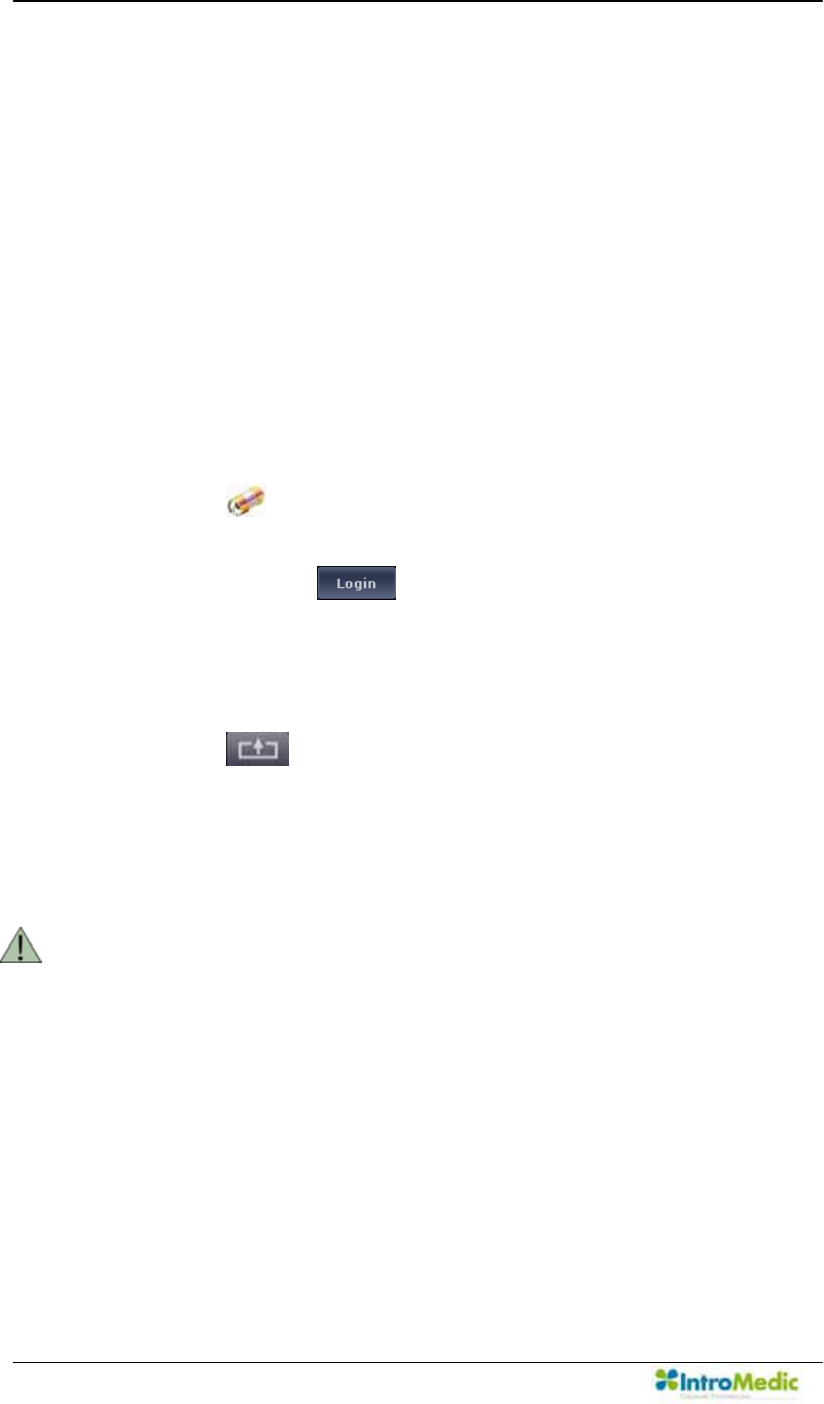
3.7 Uploading Image Data
Once the MiroCam® Capsule endoscopy procedure is complete, upload
the image data from the MiroCam® Receiver to the workstation and start
diagnosis of the data using 0LUR9LHZSoftware.
3.7.1 Transferring and Checking image data
Switch on the workstation.
Connect the smaller end of the USB cable to the MiroCam®
Receiver
Click the on the desktop to launch 0LUR9LHZOperator.
When the login window appears, enter the user ID and password,
and then click the .
Connect the smaller end of the USB cable to the MiroCam®
Receiver.
Connect the other end of the USB cable to the workstation.
Click the in 0LUR9LHZOperator.
After the image data in the MiroCam® Receiver has been
successfully uploaded, execute 0LUR9LHZ Client to review and
report on the patient file.
WARNING )RUPRUHLQIRUPDWLRQRQXVLQJ0LUR9LHZ Software please
refer to Chapter 4. 8VLQJ0LUR9LHZ Software.

Chapter 3 Performing Capsule Endoscopy
3-23
3.8 MiroCam® Receiver Management ± Post Procedure
3.8.1 Cleaning
Remove data cable (or data belt) from the MiroCam® Receiver .
Capsule, data belt and sensor pads should not be reused.
To clean the MiroCam® Receiver and the workstation, dampen a
soft cloth with warm water or with a commercial, nonabrasive
cleaner (or a mild soap or detergent solution) and wipe the
exterior surface lightly. DO NOT allow any liquids to come in
contact with the power connector, cable connector or switches.
DO NOT allow any liquids to penetrate connectors or openings in
the system cover. Cleaning of the system and accessories should
be conducted at least once a week.
CAUTION DO NOT immerse the MiroCam® Capsule Endoscope
System or its accessories in liquid or clean with caustic or
abrasive cleaners. DO NOT spray or pour any liquid on the
system or its accessories. DO NOT use the organic
solvents such as a lacquer, thinner, ethylene and oxide
because they can damage the equipment. When cleaning
the data cable, do not use the cleaning tools such as brush
and sandpaper.
Performing Capsule Endoscopy Chapter 3
3- 24
3.8.2 Charging Battery
Battery must be recharged after every procedure.
Battery can be individually recharged using the battery charger or
while attached to the MiroCam® Receiver.
Battery must be recharged in the battery charger.
If two batteries are inserted in charger, the batteries will
automatically consecutively charge (not simultaneous).
Connect adapter DC cable to battery charger.
Chapter 3 Performing Capsule Endoscopy
3-25
Connect AC power cable to adaptor.
Connect AC power cable to AC outlet or multi-tap.
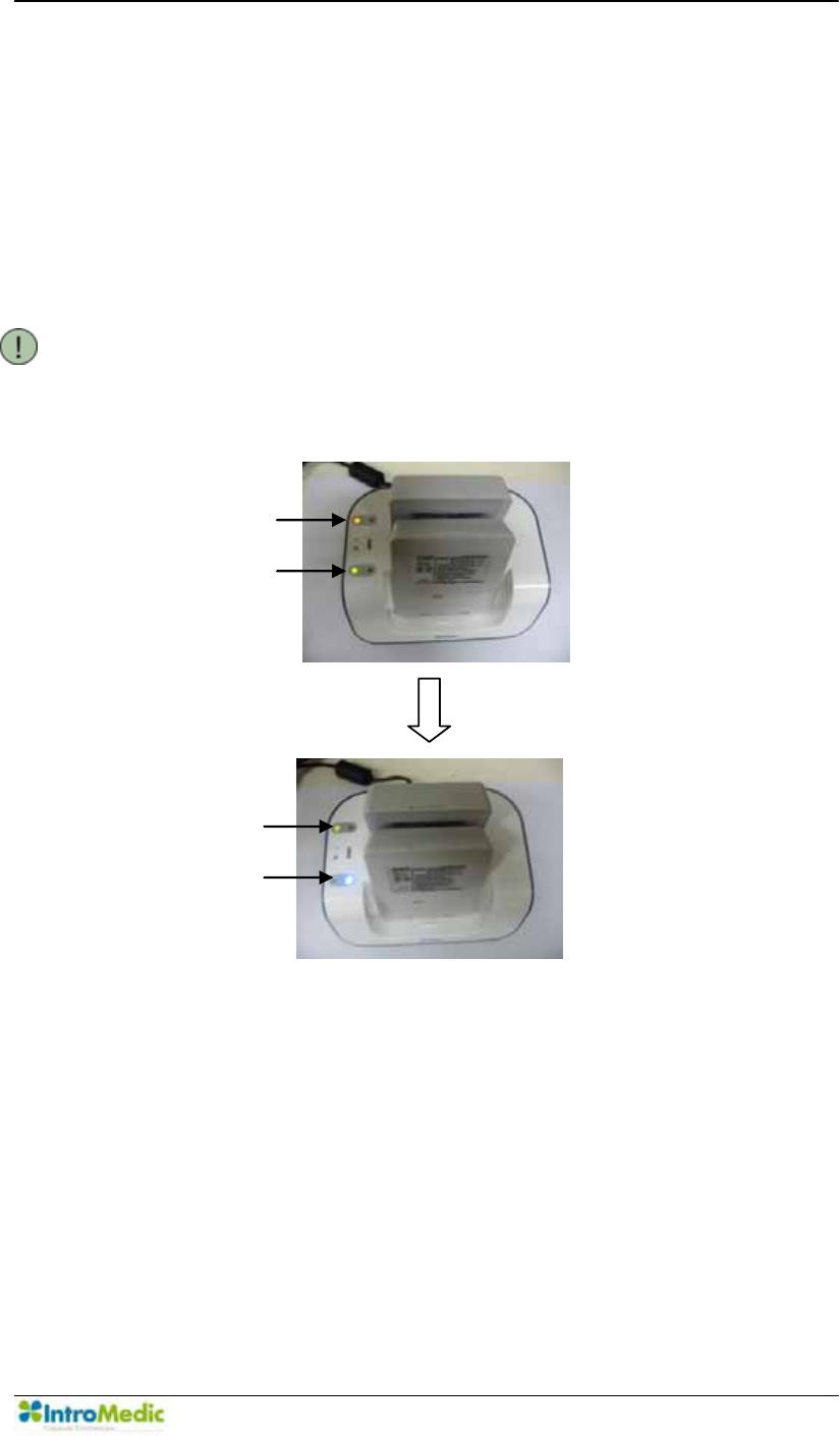
Battery charger indicator lights:
- Battery is charging when green light is blinking
- Battery is fully charged when light is solid blue
- Battery is not-charging if light is yellow
NOTE Second Battery in charger will automatically begin charging
once first battery is fully charged.
Waiting
Charging
Charging
Charged

Performing Capsule Endoscopy Chapter 3
3- 26
WARNING If the indicator on the battery charger is blinking yellow
there is a bad connection. Please disconnect the battery
from the battery charger and try again.
WARNING Only use batteries provided by IntroMedic. Usage of
inappropriate batteries can cause serious damage to the
MiroCam® Receiver.
WARNING Recharge the batteries with the adaptor and the battery
charger only from IntroMedic. Improper adaptors and
battery chargers cause serious damage.
WARNING Try not to contact the metallic terminal board of batteries
with conductive objects or human body. It can cause an
electric shock or damage and/or breakage of the
batteries.
WARNING DO NOT use the batteries with visible surface damage
on. Usage of damaged batteries can result in leakage of
contents of the batteries.
WARNING To avoid the risk of explosion, keep batteries away from
fire.
WARNING Treat the batteries carefully from serious impact or shock.
This can cause serious damage to the batteries.
WARNING DO NOT expose the batteries to liquids. This can cause
serious damage.

4
8VLQJ0LUR9LHZSoftware

Using MiroView Software Chapter 4
4- 2

Chapter 4 Using 0LUR9LHZ Software
4-3
4. USING 0,529,(: SOFTWARE
The 0LUR9LHZ Software is a computer software program that aids in
diagnosis of disease of the small bowel via displaying images obtained from
the MiroCam® Capsule.
Following is a list of new & updated features:
- User Interface
The 0LUR9LHZ Software enables adjustable resolution, to
appropriately fit to the screen size.
The 0LUR9LHZ Software has been designed with a dark
background to reduce eye strain.
The 0LUR9LHZSoftware provides intuitive and unified icons so that
the user can adapt quickly.
- Reporting Tool
- Express Play
- SGIB Play
- Range View
- Map View
- Network Support
- Account Management
- Multi-Review / Report Generation
- Multi-Receiver Management
- Multi-Data Path
- Customizing Print Dialog
- Data Multi-Language
- ODF Report
- Drag Bag
- Finding Setting (Custom Finding)

Using MiroView Software Chapter 4
4- 4
The workstation where the 0LUR9LHZ Software is installed properly has
icons for four applications on the Desktop folder: 0LUR9LHZ Client,
0LUR9LHZOperator, 0LUR9LHZServer, and 0LUR9LHZViewer. However
this manual will not explain details on how to use the 0LUR9LHZViewer. For
additional information for 0LUR9LHZViewer, please refer to the 0LUR9LHZ
9LHZHU,QVWUXFWLRQ 0DQXDO 7RJHW WKH LQVWDOODWLRQ SURFHGXUH IRU0LUR9LHZ
Software, refer to the MiroCam® Service Manual.

Chapter 4 Using 0LUR9LHZ Software
4-5
0LUR9LHZClient
0LUR9LHZOperator
0LUR9LHZServer
0LUR9LHZViewer
This program is used
for reviewing the
images from the
MiroCam® Capsule
and generating a
patient report. The
0LUR9LHZServer
should be started prior
to starting the
0LUR9LHZClient.
This program is used
for managing the
MiroCam® Receivers
(initialize, upload etc.)
and managing user
accounts. The
0LUR9LHZServer
should be started prior
WRVWDUWLQJ0LUR9LHZ
Operator.
The server stores the
patient data files. Start
the 0LUR9LHZ
Server prior to starting
0LUR9LHZSoftware
or 0LUR9LHZ
Operator.
The
0LUR9LHZViewer is
used for reviewing,
editing and creating
the images exported
IURPWKH0LUR9LHZ
Software; EXMIF or
JPEG images.
Functions:
- List Mode
- Review Mode
- Report Mode
- Export Mode
- Image Atlas
- SGIB
(Suspected
GI Bleeding)
- Express Play
- Position Window
- Network connectivity
- Multi-Review
- Range View
- Map View
- GI Dictionary
- Finding / Diagnosis
Information
- Drag Bag
Functions:
- Input Patient
Information
- Receiver
Initialization
- Upload Image Data
from Receiver
- Data Backup
- Account
Management
- Patient Manager
-Network connectivity
Functions:
- DB, Mass storage
-Network connectivity
- Multiple Data Path
Functions:
- Study Information
- Image Information
- Show Findings /
Diagnosis

Using MiroView Software Chapter 4
4- 6
4.1 H/W Specifications for 0LUR9LHZ Software
4.1.1 0LUR9LHZServer
Minimum Hardware Requirements
- OS: Windows XP (32 bit, 64 bit),
Windows Vista Business (32 bit, 64 bit),
Windows 7 (32 bit, 64 bit)
- CPU: > Core 2 Duo E6300
- Memory: > DDR II 4GByte
- Video Card: Windows Compatible
- HDD: SATA 500GB
- ODD: DVD+-RW
- Monitor Resolution: 1024x768
Recommended Hardware Requirements
- OS: Windows XP (32 bit, 64 bit),
Windows Vista Business (32 bit, 64 bit),
Windows 7 (32 bit, 64 bit)
- CPU: > Core 2 Duo E6300
- Memory: > DDR II 4GByte
- Video Card: Windows Compatible
- HDD: SATAII RAID 1TB
- ODD: DVD+-RW
- Monitor Resolution: 1680x1050, 1280 x 1024

Chapter 4 Using 0LUR9LHZ Software
4-7
4.1.2 0LUR9LHZClient
Minimum Hardware Requirements
- OS: Windows XP (32 bit, 64 bit),
Vista or Windows7 (32 bit, 64 bit)
- CPU: Pentium4 2GHz
- Memory: 1GB
- Video Card: Geforce 7600GT 128MB
- HDD: SATA 160GB
- ODD: DVD+-RW
- Monitor Resolution: 1024x768
- Sound Card / Mike / Speaker
Recommended Hardware Requirements
- OS: Windows XP (32 bit, 64 bit),
Vista or Windows7 (32 bit, 64 bit)
- CPU: > Core 2 Duo E6300
- Memory: > DDR II 2GByte
- Video Card: > Geforce 7600GT 128MB
- HDD: SATA II 500 GB
- ODD: DVD+-RW
- Monitor Resolution: 1680x1050
- Sound Card / Mike / Speaker

Using MiroView Software Chapter 4
4- 8
4.1.3 0LUR9LHZOperator
Minimum Hardware Requirements
- OS: Windows XP (32 bit, 64 bit),
Vista or Windows7 (32 bit, 64 bit)
- CPU: Pentium4 2GHz
- Memory: 1GB
- Video Card: Windows Compatible
- HDD: SATA 160GB
- ODD: DVD+-RW
- Monitor Resolution: 1024x768
Recommended Hardware Requirements
- OS: Windows XP (32 bit, 64 bit),
Vista or Windows7 (32 bit, 64 bit)
- CPU: > Core 2 Duo E6300
- Memory: 1GB
- Video Card: Windows Compatible
- HDD: SATA 160GB
- ODD: DVD+-RW
- Monitor Resolution: 1680x1050
Chapter 4 Using 0LUR9LHZ Software
4-9
4.1.4 0LUR9LHZViewer
Hardware Requirements
- OS: Windows XP (32 bit, 64 bit),
Vista or Windows7 (32 bit, 64 bit)
- CPU: Pentium4 2GHz
- Memory: 1GB
- Video Card: Windows Compatible
- HDD: SATA 160GB
- ODD: DVD+-RW
- Monitor Resolution: 1024x768
CAUTION The 0LUR9LHZ Software cannot be viewed on a monitor
with a resolution under 1024x768.
NOTE 7KH*8,LVEHVWYLHZHGRQDZLGHPRQLWRURI´RUODUJHU
Using MiroView Software Chapter 4
4- 10
4.2 Overview ± 0LUR9LHZServer
The 0LUR9LHZ Server software is intended to be used as a system
administrative managing tool. The 0LUR9LHZ Server manages file
systems and database systems.
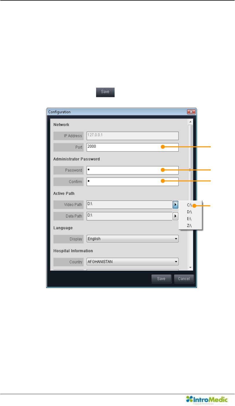
When switching the workstation on, the 0LUR9LHZ Server will start
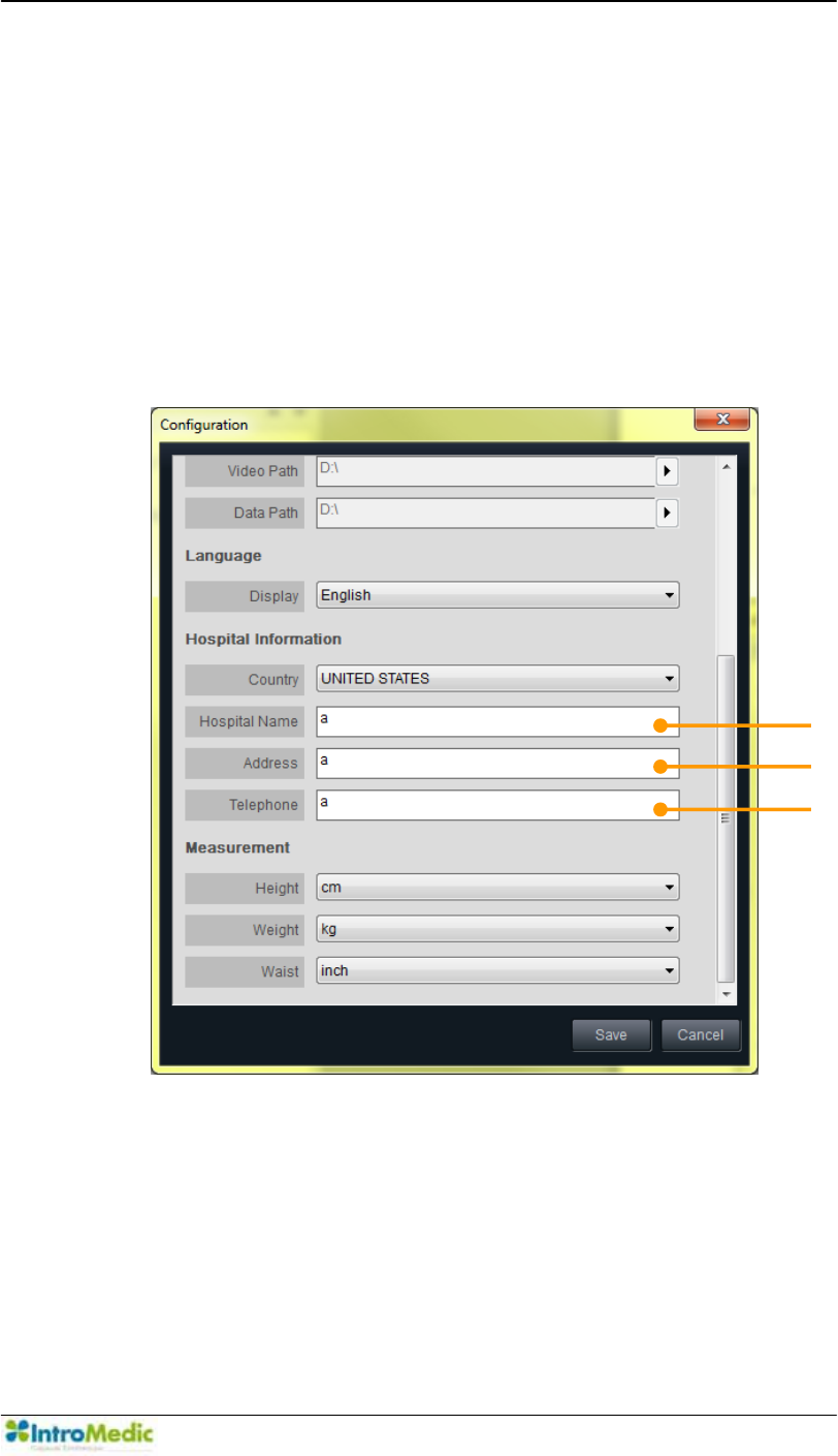
automatically. When the following window appears, set up the
configuration and press the to continue.
ཛ Set the port number for the Network. If unknown, please leave the
ILHOG DV µ¶ 7KLV ILHOG VKRXOG EH PDQDJHG E\ D 1HWZRUN
Administrator at the hospital.
c
d
e
f
Chapter 4 Using 0LUR9LHZ Software
4-11
ཛྷ 6HW WKH SDVVZRUG IRU µ$GPLQLVWUDWRU¶ DFFRXQW $GGLWLRQDO DFFRXQWV
can be made via Account Manager function after logging in the
0LUR9LHZ2SHUDWRUDVµ$GPLQLVWUDWRU¶
ཝ Confirm the password.
ཞ Set the Active Path; Video Path and Data Path as the desirable
path. Select one of multiple paths from the paths list for the active
path. The paths list can be modified via Server Menu Æ Multi Data
Path on the 0LUR9LHZServer running.
§ ,QSXWWKH+RVSLWDO¶V1DPHLQWKLVILHOG
འ ,QSXWWKH+RVSLWDO¶VAddress in this field.
ཡ ,QSXWWKH+RVSLWDO¶V7HOHSKRQHQXPEHULQWKLVILHOG
g
h
i
Using MiroView Software Chapter 4
4- 12
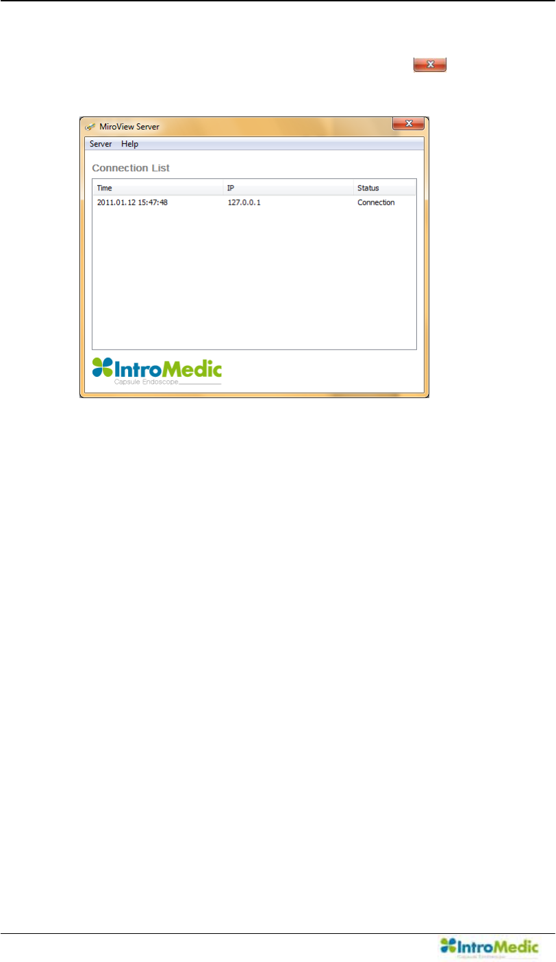
After setting up the Configuration Windows, the 0LUR9LHZ
Server window above will appear. Click the to hide the
window.
Chapter 4 Using 0LUR9LHZ Software
4-13
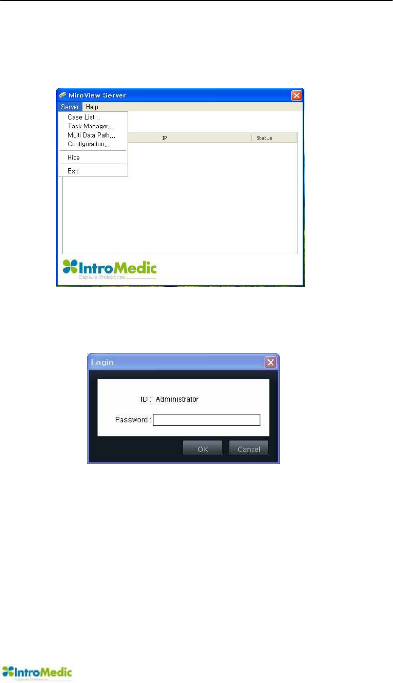
The Video Path list and the Data Path list for the Active Paths can
be modified via Server Menu Æ Multi Data Path on the
0LUR9LHZServer running.
- Login window will appear. Input the password for the
Administrator account.
Using MiroView Software Chapter 4
4- 14
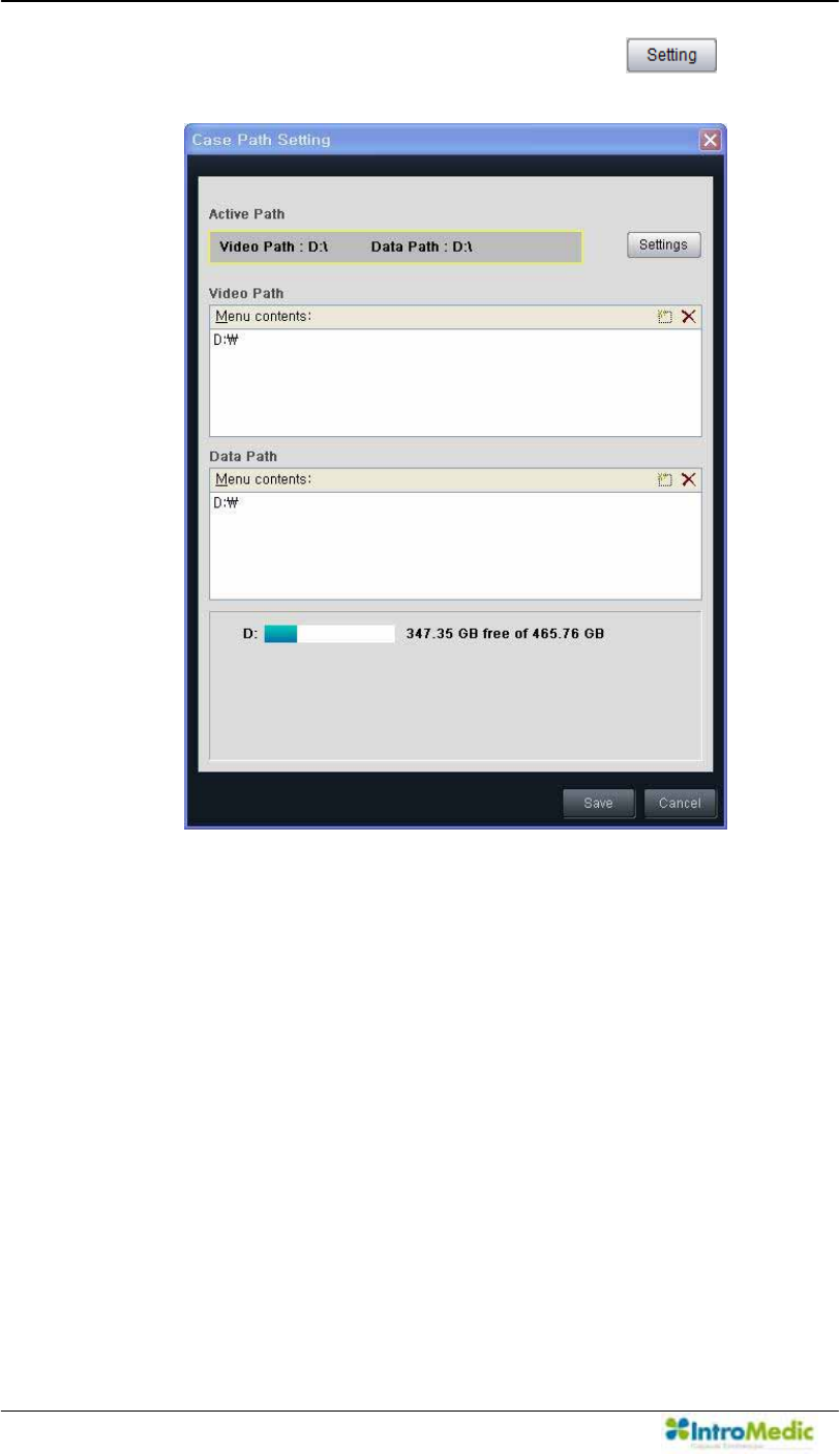
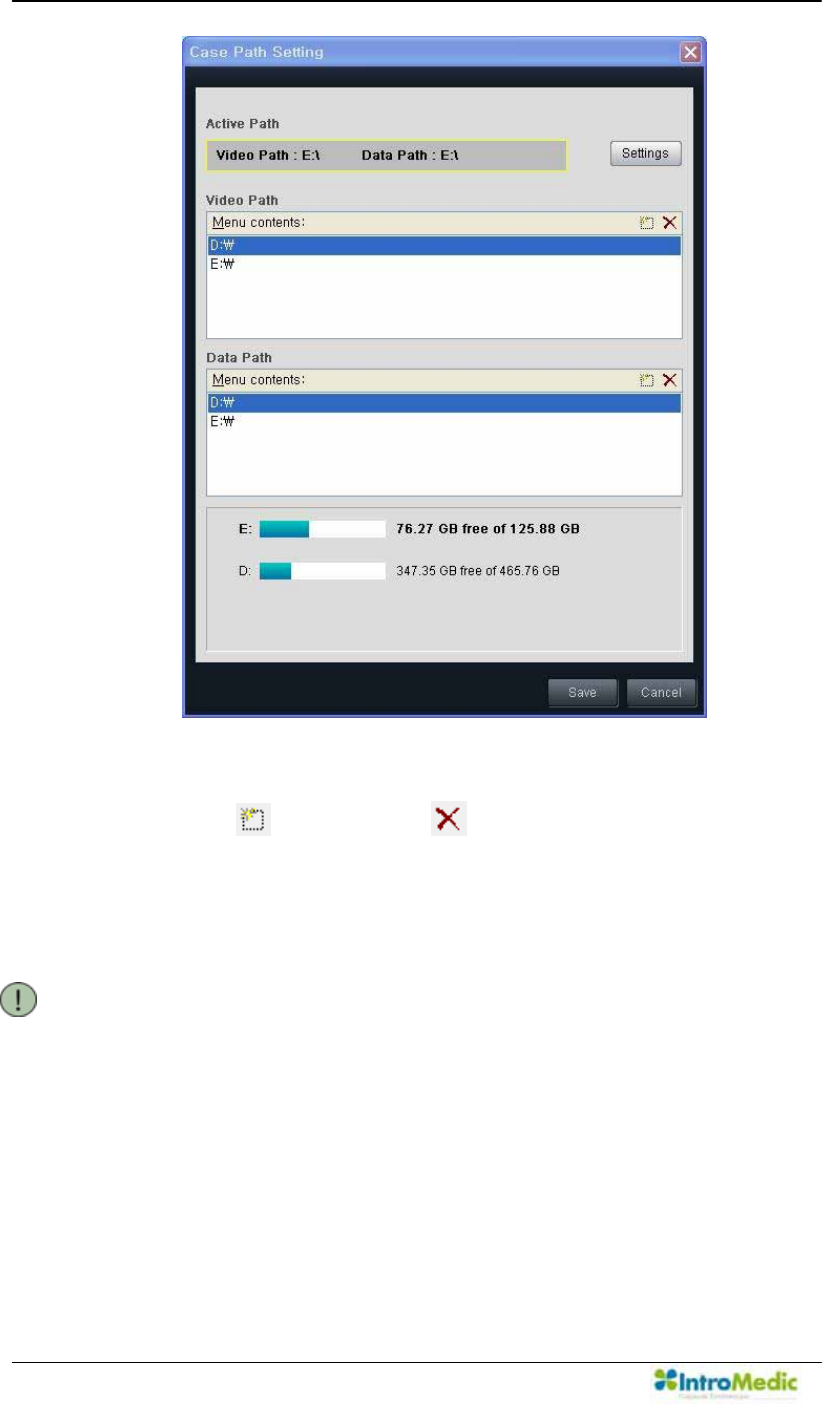
- Case Path Setting will appear. Click the to show
the Active Path Setting.
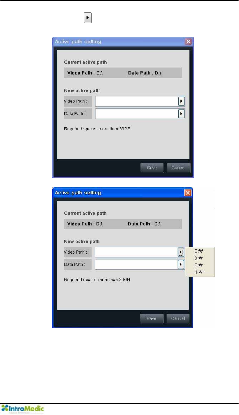
Chapter 4 Using 0LUR9LHZ Software
4-15
- Click the to set the path for the Video Path and the
Data Path respectively.
Using MiroView Software Chapter 4
4- 16
- The user can modify the Video Path and Menu Path using
the (add path) and (remove path) as well.
- ,I WKH $FWLYH 3DWK¶ PHPRU\ EHFRPHV LQVXIILFLHQW WR XVH
(below 10GBytes), set the path as new one larger than 30
GB.
NOTE The 0LUR9LHZ Server provides the task manager to show
the activating status on the server. The 0LUR9LHZ Server
offers the case list and the analysis function as well.
Chapter 4 Using 0LUR9LHZ Software
4-17
4.3 Overview - 0LUR9LHZOperator
The 0LUR9LHZ Operator software is intended to be used for
administrative purposes, including the Account Manager, the Patient
Manager and the MiroCam® Receiver management functionality.
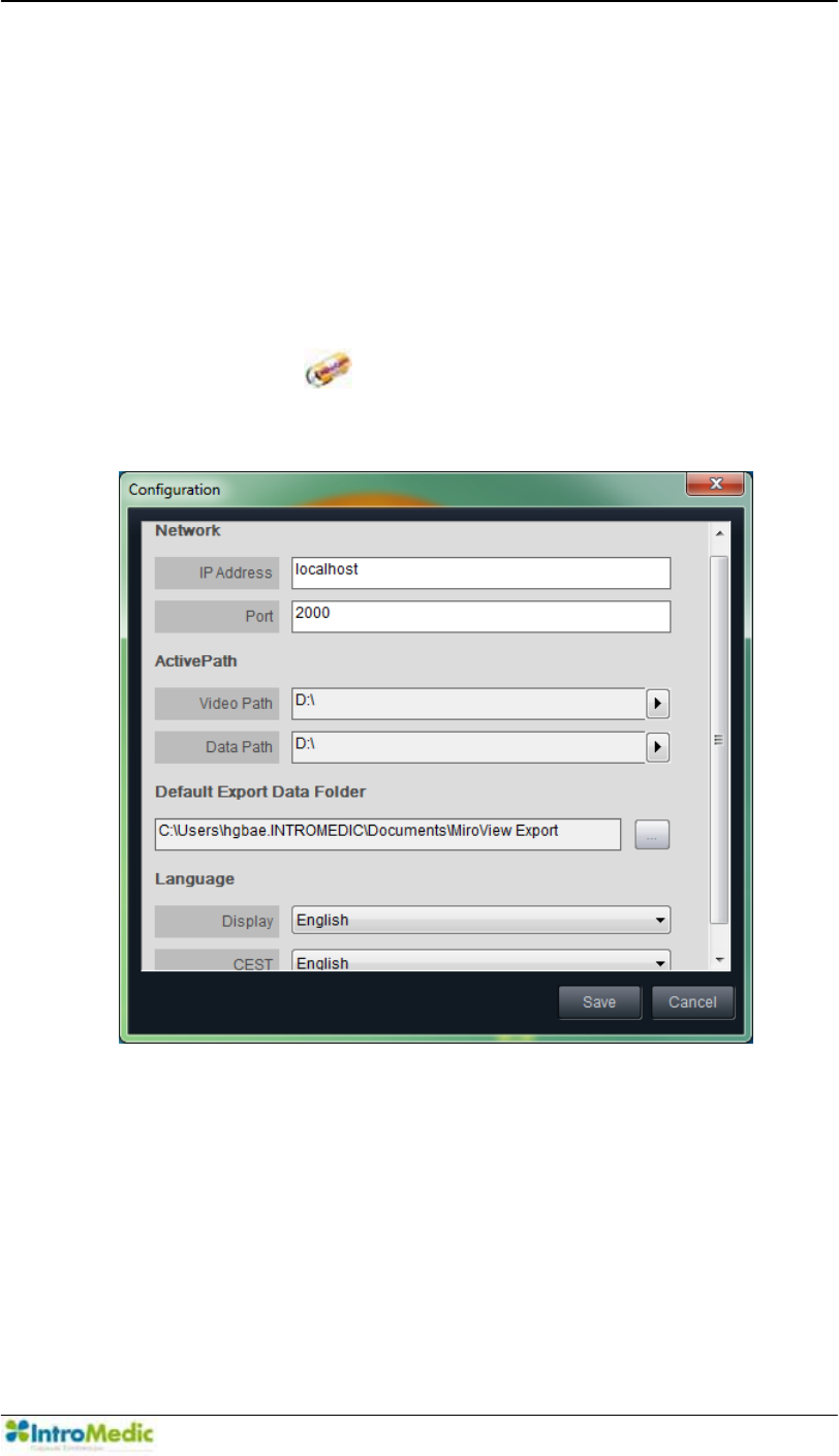
4.3.1 Start 0LUR9LHZOperator
Double-click the to run the 0LUR9LHZ Operator. When
executed for the first time, the following window will appear.
,QSXW³´IRUWKH,3$GGUHVVDQG³´IRUWKH3RUW
ଖ If the 0LUR9LHZ Server is installed on the network, input the
workstation¶V,3RQZKLFKWKH0LUR9LHZServer is installed for
this field, and the port which the 0LUR9LHZ Server is using,
referring to the IT engineer in the hospital to point the operator
to the 0LUR9LHZServer.
Using MiroView Software Chapter 4
4- 18
Set the Active Path; Video Path and Data Path as the desirable
path. Select one of multiple paths from the paths list for the active
path.
Direct the Default Export Data Folder.
Choose the preferred Language settings and press to
access the 0LUR9LHZOperator.
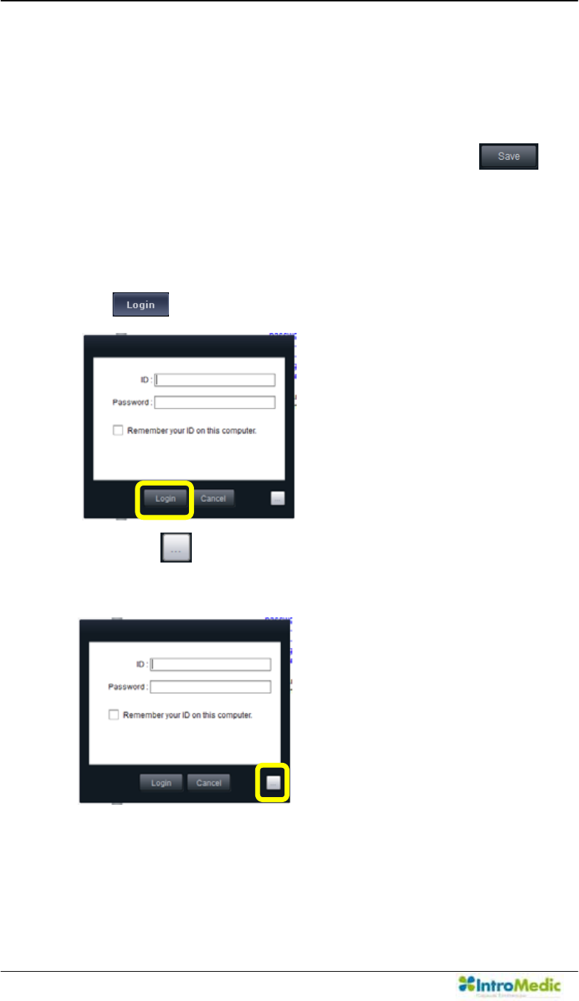
After the 0LUR9LHZOperator has launched, the Log-in window
will appear.
,QSXWµ$GPLQLVWUDWRU¶IRU,'DQGGHVLJQDWHGSDVVZRUG7KHQSUHVV
the .
Press the to change the IP address the 0LUR9LHZServer
is using.
Chapter 4 Using 0LUR9LHZ Software
4-19
After clicking the the window will appear like the above.
Type the 0LUR9LHZServer IP address and port. Then press the
after inputting ID and password.
CAUTION DO NOT forget the ID and password after they are
encrypted.
CAUTION Before the 0LUR9LHZ Operator is launched, a password
for the administrator account should be created. When
running the 0LUR9LHZ Server for the very first time, a
password for the administrator account should be created.
NOTE Create new and edit existing accounts by using the
µAccount Manager¶ menu in 0LUR9LHZ Operator.
The following subsections describe the main interfaces and
functions of the 0LUR9LHZOperator.
Using MiroView Software Chapter 4
4- 20
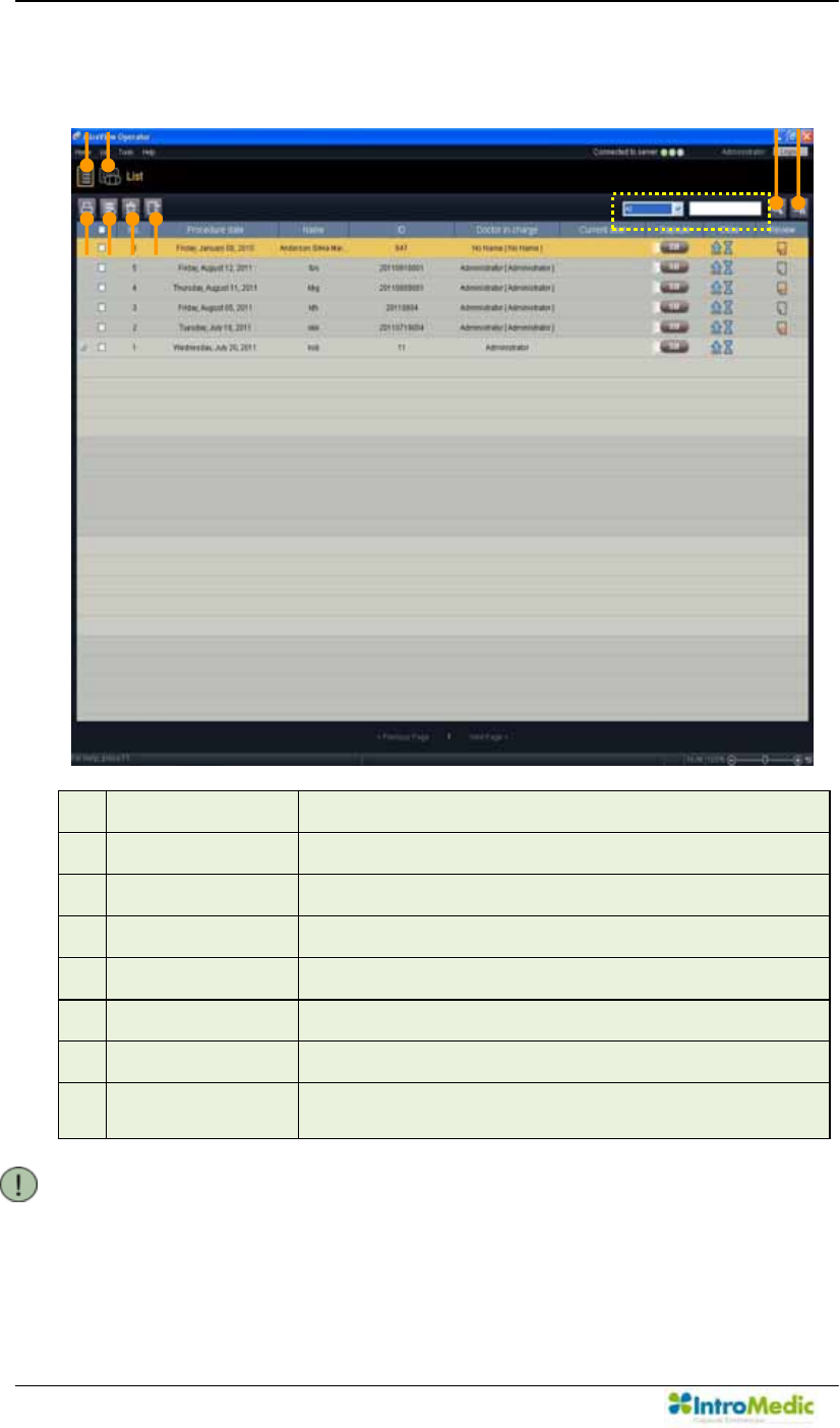
4.3.2 List Mode
£ List Mode Opens List Mode
¤ Receiver Mode Opens Receiver Mode
¥ Print Report Print out the selected Report
¦ Delete Case Delete the selected Cases
§ Recycle Bin Open Recycle Bin Window
¨ Export Export the selected Report
© Search Search Cases and/or Reviews by keyword
ª Show all Refresh and Show all the Cases and Review on
the List
NOTE Right click the mouse at the list item to use the context menu
functionality, for example the Backup function.
e
f
g
i
j
c
d
h
Chapter 4 Using 0LUR9LHZ Software
4-21
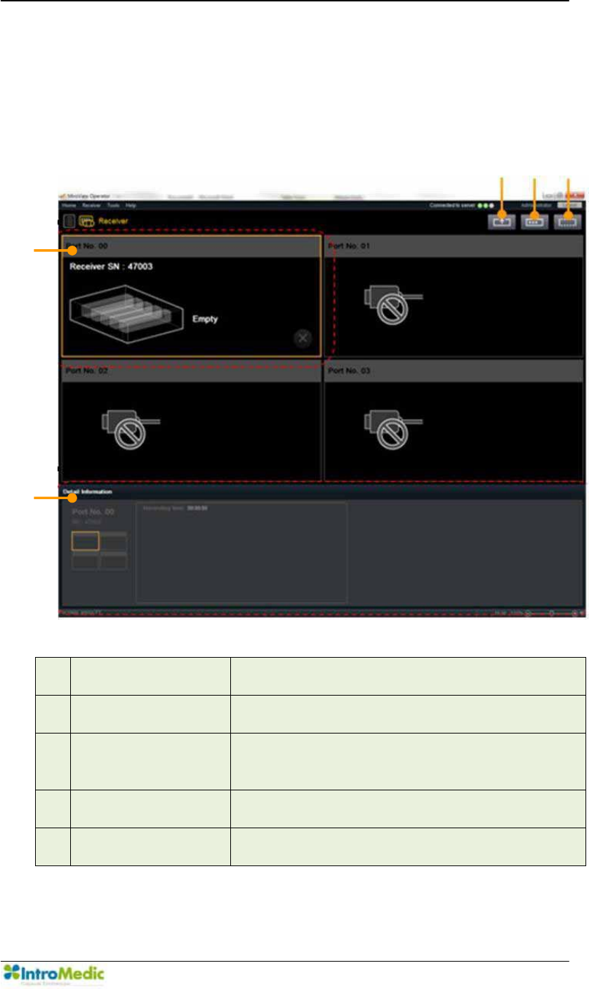
4.3.3 Receiver Mode
Screen enables administration and status display for up to four
MiroCam® Receivers.
£ Upload Upload image data in the MiroCam® Receiver
to the server
¤ ,QSXW 3DWLHQW¶V
Information
,QSXW 3DWLHQW¶V ,QIRUPDWLRQ WR WKH VHOHFWHG
Receiver
¥ Initialization Delete all data from the MiroCam® Receiver
and/or prepare the MiroCam® Receiver for the
next patient
¦ Receiver Port Shows the status of the connected the
MiroCam® Receiver for each of the four ports
§ Detail Information 6KRZV WKH SDWLHQW¶V LQIRUPDWLRQ IRU WKH
selected Receiver
¥
¦
c
d
e
Using MiroView Software Chapter 4
4- 22
CAUTION When running MiroView Operator on a 64bits
OS, Do not turn off or disconnect the MiroCam®
Receiver while uploading a patient file.
4.3.4 Receiver Initialization
Click the to initialize the selected Receiver.
Chapter 4 Using 0LUR9LHZ Software
4-23
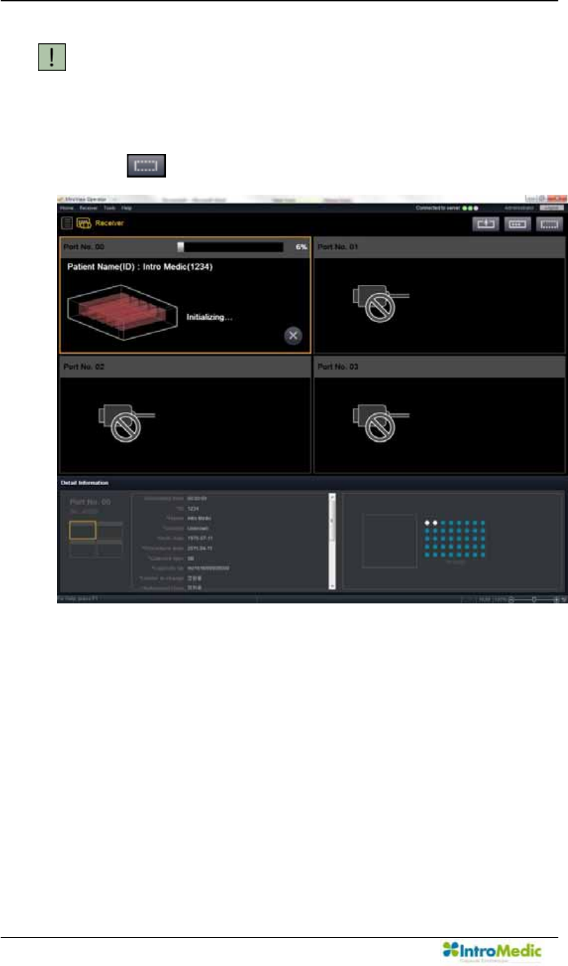
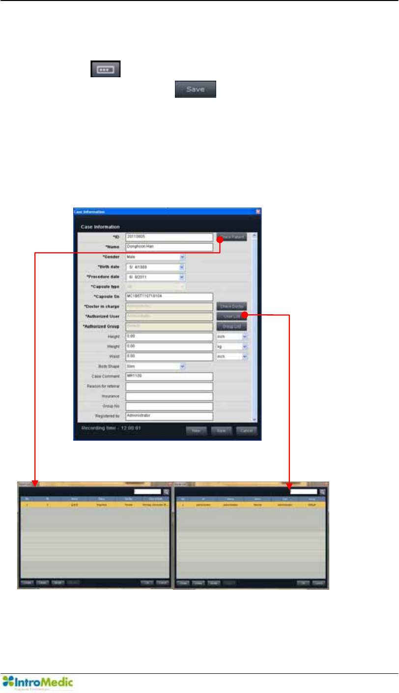
4.3.5 Inputting Patient Information
Click the to enter the patient information. After completing the
required fields, click the to save the patient information
onto the MiroCam® Receiver. The fields in the patient information
are editable and additional fields can be added. This can be
accessed via Tools Æ Preferences Æ Receiver Æ Set Æ Add /
0RGLI\ 7KH ILHOG ³5HDVRQ IRU UHIHUUDO´ LV QHZO\ DGGHG RQ WKH
0LUR9LHZ Software version.)
* indicates required fields.
Using MiroView Software Chapter 4
4- 24
4.3.6 Image Data Upload
After the MiroCam® Capsule endoscopy procedure, upload the
image data from the MiroCam® Receiver to the MiroCam® system
via the 0LUR9LHZ Operator. Click the to upload the image
data from the MiroCam® Receiver.
After the image data in the MiroCam® Receiver has been
successfully uploaded, enter the List Mode and check if the new
Case has been created.
- Double-click the to run the 0LUR9LHZClient.
- Select the newly uploaded image data and enter the Review Mode.
- Play the case to check the uploaded image data.
CAUTION If uploading of the image data failed, disconnect
the USB cable from the workstation, turn off the
MiroCam® Receiver and back on. Reconnect the
USB cable to the workstation and try uploading
once more. If the problem continues, please
contact the local IntroMedic distributor.
NOTE 0DNH VXUH WKH SDWLHQW¶V QDPH KDV EHHQ LQSXWWHG
properly prior to uploading the image data. If the
image data is uploaded with the wrong patient
name, it could result in misdiagnosis or delay in
diagnosis.
NOTE If the user uploads an image data which has been
XSORDGHGEHIRUHDQHUURUPHVVDJHµ'DWDKDVEHHQ
previously uploaded. Would you like to upload
agDLQ"¶ZLOODSSHDU
NOTE The user can stop the uploading of the image data
while uploading process file by clicking the .
Chapter 4 Using 0LUR9LHZ Software
4-25
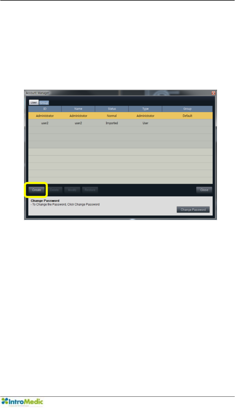
4.3.7 User Account Management
The 0LUR9LHZOperator enables management of multiple users &
Groups. Users can be organized into Groups to readily control
access. The following screen can be accessed by Tools Æ Account
Manager.
Using MiroView Software Chapter 4
4- 26
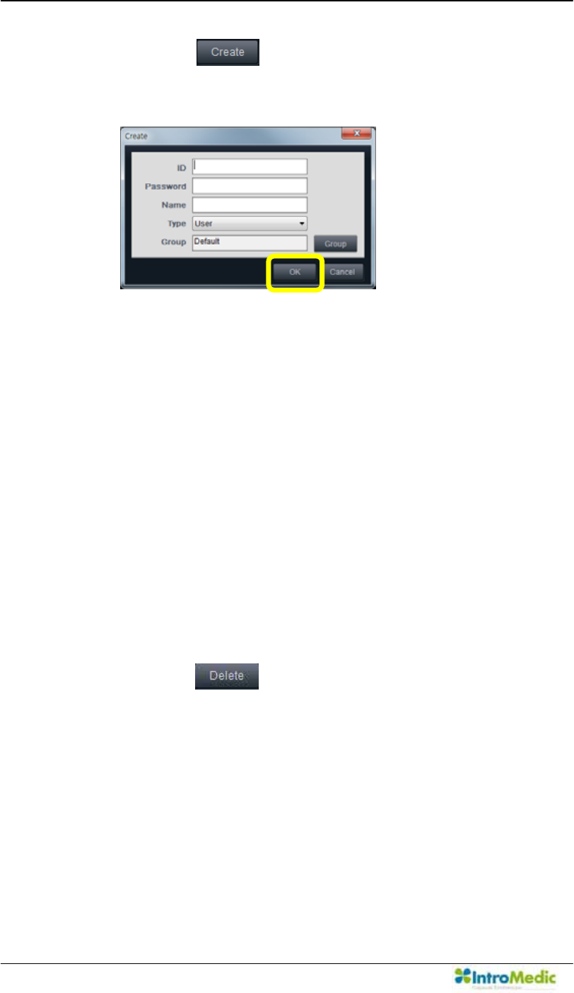
Click the to show the window as displayed below
to create a new user ID.
ID: User ID
Password: Password
Name: User Name
Type: User type.
- User: can access own reviews and all the reviews in the
*URXSRIWKH8VHU¶VRQO\
- Super User: can access all the reviews in the System
- Operator: can log in via the 0LUR9LHZ Operator S/W
only.
Administrator account can log in via both the
0LUR9LHZ Client and the 0LUR9LHZOperator.
Group: Set of users in the same Clinic or Laboratory.
Click the to delete the selected account
Chapter 4 Using 0LUR9LHZ Software
4-27
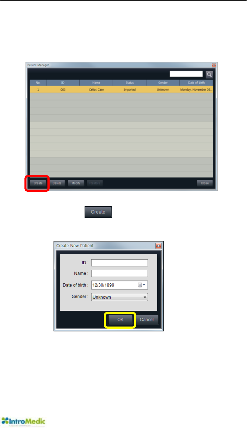
4.3.8 Patient Manager
The 0LUR9LHZ Operator enables management of Patient. The
following screen can be accessed by Tools Æ Patient Manager
Click the to show the window as displayed below
WRFUHDWHDSDWLHQW¶V,'
ID: ID for the new patient.
Name3DWLHQW¶VQDPH
Date of birth: The date of birth for the patient which will
appear on the report
Gender7KHSDWLHQW¶VJHQGHU
Using MiroView Software Chapter 4
4- 28
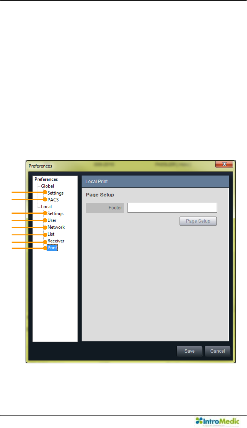
4.3.9 Preferences
To set and/or change the settings for the 0LUR9LHZ Operator,
access Preferences via Tools Æ Preferences.
Preferences for the 0LUR9LHZ Operator falls into two categories:
Global and Local.
Global preference is saved on the 0LUR9LHZ Server and has in
effect for all the users using the 0LUR9LHZServer.
Local preference is saved on the workstation on which the
0LUR9LHZOperator is installed and has in effect for the workstation
only.
i
c
d
e
f
g
h
j

Chapter 4 Using 0LUR9LHZ Software
4-29
Global £ Settings - Hospital Information
- Measurement
- Agent & Distributor Information
¤ PACS - PACS Registration
- Technical Settings
Local ¥ Settings - Language
- GI Tract Color Reference
- Free Hard Disk
- Display
- Default Export Data Folder
- Finding Setting
¦ User - 8VHU¶V,QIRUPDWLRQ
- Change Password
§ Network - 0LUR9LHZServer
- Server Manager
¨ List - Display ± Show/Hide Columns
© Receiver - Patient Information Configuration
- Multiple Upload
ª Print - Page Setup
Using MiroView Software Chapter 4
4- 30
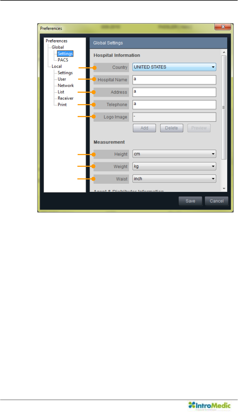
1) Global Settings
i. Hospital Information
ཛ Country ± Choose the Country where the hospital is located.
ཛྷ Hospital Name ± ,QSXWWKH+RVSLWDO¶V1DPHLQWKLVILHOG
ཝ Address ± ,QSXWWKH+RVSLWDO¶V$GGUHVVLQWKLVILHOG
ཞ Telephone ± ,QSXWWKH+RVSLWDO¶V7HOHSKRQHQXPEHULQWKLV
field.
ཟ Logo Image ± Add the Logo Image
These information will be applied and shown on the final
report.
§
¨
©
¢
£
¤
¥
¦
Chapter 4 Using 0LUR9LHZ Software
4-31
ii. Measurement
འ Height ± &KRRVHWKHPHDVXUHPHQWXQLWIRUSDWLHQW¶VKHLJKW
ཡ Weight - &KRRVHWKHPHDVXUHPHQWXQLWIRUSDWLHQW¶VZHLJKW
ར Waist - &KRRVHWKHPHDVXUHPHQWXQLWIRUSDWLHQW¶VZDLVW
These information will be applied and shown on the case
information and patient information
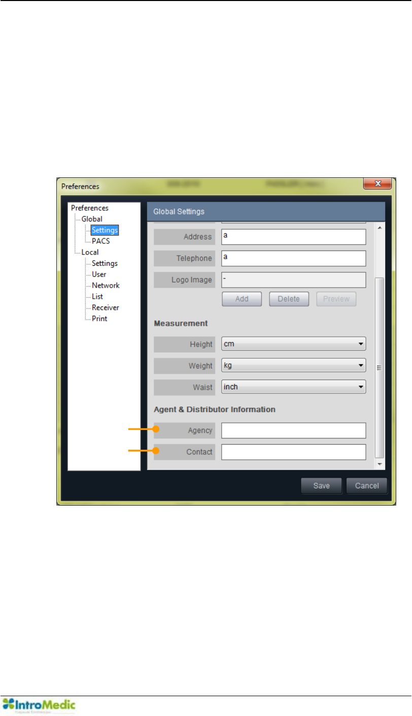
iii. Agent & Distributor Information
ལ $JHQF\,QSXWWKH$JHQF\¶VLQIRUPDWLRQLQWKLVILHOG
ཤ Contact: Input the contact information for the agency.
ª
«
Using MiroView Software Chapter 4
4- 32
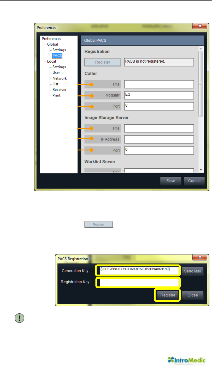
2) Global PACS
i. Registration: Process to enable the PACS related
functionalities.
- Click the . PACS registration window will
appear like the below.
- Carry out in alphabetical order like following picture.
NOTE Generation key is a key that unlocks the PACS
function on the MiroCam® workstation.
¢
£
¤
§
¦
¥
Ú
Û
Ü
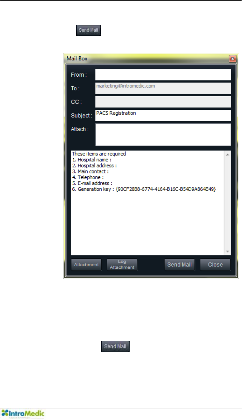
Chapter 4 Using 0LUR9LHZ Software
4-33
- Generation key will be generated automatically. Click
the to send the Generation key to IntroMedic.
Mail Box window will appear like below.
- Input the e-mail address of the hospital administrator in
WKH µ)URP¶ ILHOG ,QSXW DOO WKH UHTXLUHG LQIRUPDWLRQ WR
send to IntroMedic: Hospital name, Hospital address,
Main contact, Telephone, E-mail address and
Generation key.
- Click the to send the information to
IntroMedic. IntroMedic will reply with the Registration
Key to the

Using MiroView Software Chapter 4
4- 34
e-PDLO DGGUHVV W\SHG LQ µ)URP¶ ILHOG ,W ZLOO WDNH WLPH WR
receive the reply.
- Click the to close the Mail Box window.
- After receiving the Registration Key, input the Key in the
Registration Key field on PACS registration window.
Click the to finalize the registration process.
ii. Caller: Technical properties for Caller.
ཛ Title: Input the Title for Caller.
ཛྷ Modality: Input the Modality for Caller.
ཝ Port: Input the port number to use for Caller.
iii. Image Storage Server: Technical properties for Image
Storage.
ཞ Title: Input the title for Image Storage Server.
ཟ IP Address: Input the IP Address for Image Storage Server.
འ Port: Input the port number to connect to Image Storage
Server.
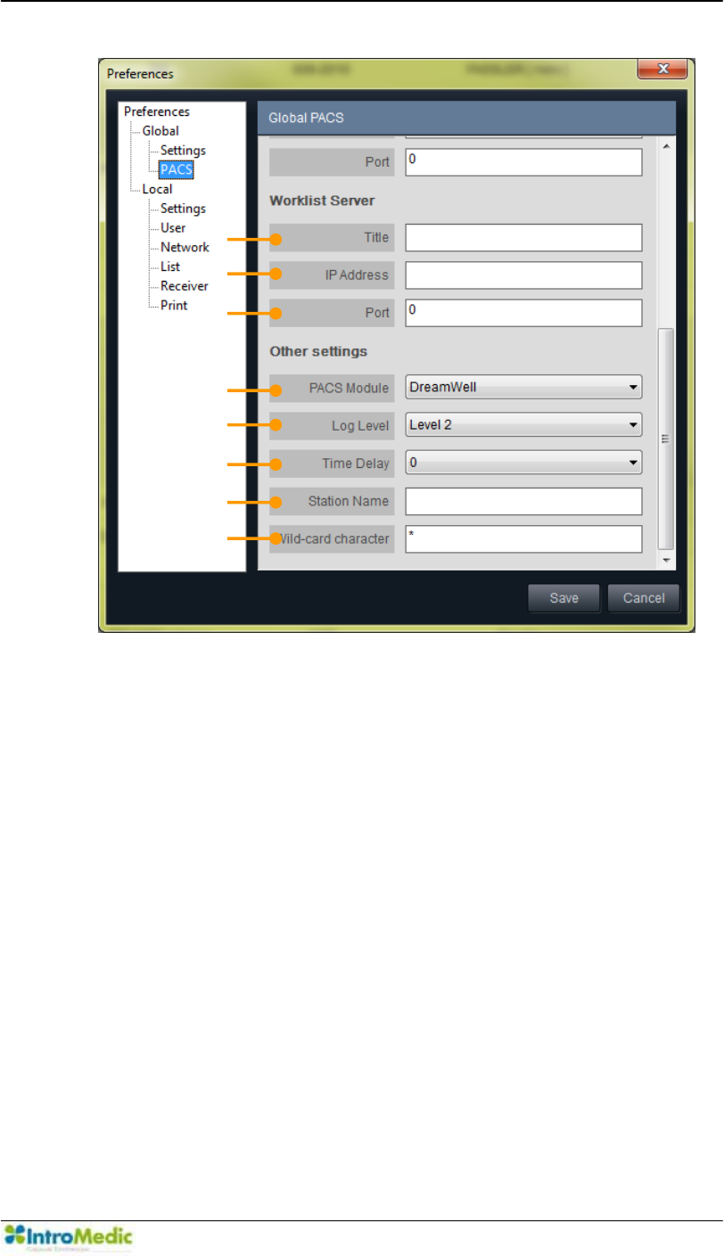
Chapter 4 Using 0LUR9LHZ Software
4-35
iv. Work list Server: Technical property for Work list Server.
ཡ Title: Input the Title for Work list Server.
ར IP Address: Input the IP Address for Work list Server.
ལ Port: Input the port number to connect to Work list Server.
v. Other Settings: Technical properties for PACS setting.
ཤ PACS Module: Choose the appropriate PACS Module,
DreamWell or Vieworks.
ཥ Log Level: Choose the appropriate Log Level for the PACS
functionality: Level 0, Level 1 and Level 2.
ས Time Delay
Choose the Time delay from 0 to 9 seconds.
ཧ Station Name
ཨ Wild-card character
¯
®
¬
ª
©
¨
«
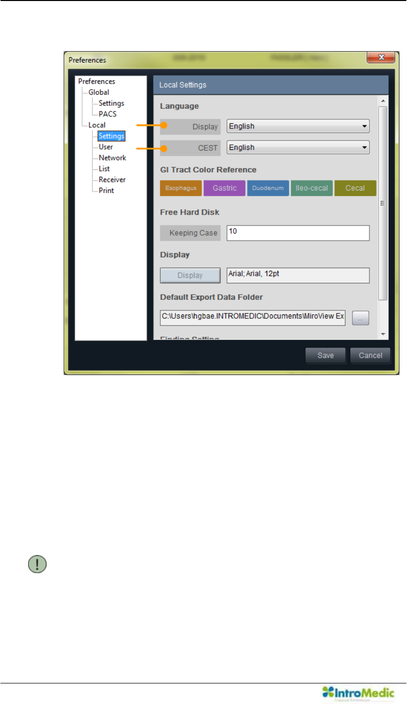
Using MiroView Software Chapter 4
4- 36
3) Local Settings
i. Language
ཛ Display: Choose the display language.
ཛྷ CEST: Choose the CEST language.
ii. GI Tract Color Reference: Show the color references for the
GI Tract.
Free Hard Disk: Decide the number of cases on the local
drive.
NOTE If the number of cases saved from the Server is more
than the number of Keeping Case, it will automatically
delete the oldest cases from the local drive.
¢
£
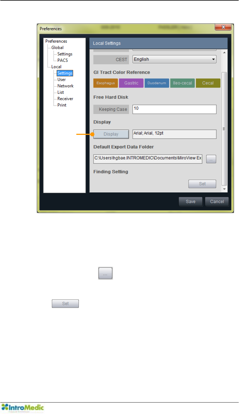
Chapter 4 Using 0LUR9LHZ Software
4-37
iv. Display
ཝ Display: Font setting to display.
v. Default Export Data Folder: Direct the folder for exporting
data. Click the to open the browser.
vi. Finding Setting: Configure the finding setting. Click the
to open the configuration dialogue.
¤
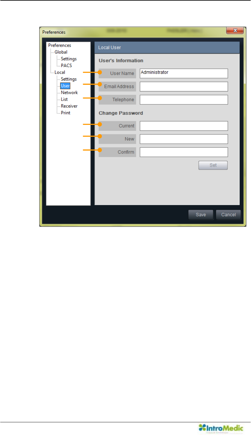
Using MiroView Software Chapter 4
4- 38
4) Local User
i. 8VHU¶V,QIRUPDWLRQ6HWPRGLI\WKHLQIRUPDWLRQIRUWKHXVHU
ཛ User Name: Input User Name which will be used for log-in
ID.
ཛྷ Email Address: Type in the e-mail address here.
ཝ Telephone: Type in the telephone number here.
ii. Change Password
ཞ Current: Input the current password
ཟ New: Input the desired password to use.
འ Confirm: Input the desired password again.
¢
£
¤
¥
¦
§
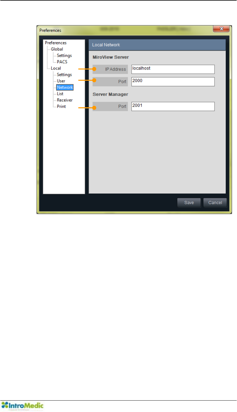
Chapter 4 Using 0LUR9LHZ Software
4-39
5) Local Network
i. 0LUR9LHZServer
ཛ IP Address: Input the IP Address where the 0LUR9LHZ
Server is installed.
ཛྷ Port: Input the port number to connect with 0LUR9LHZ
Server.
ii. Server Manager
ཝ Port: Input the port number for connection between the
Server Manager and the 0LUR9LHZServer.
¢
£
¤
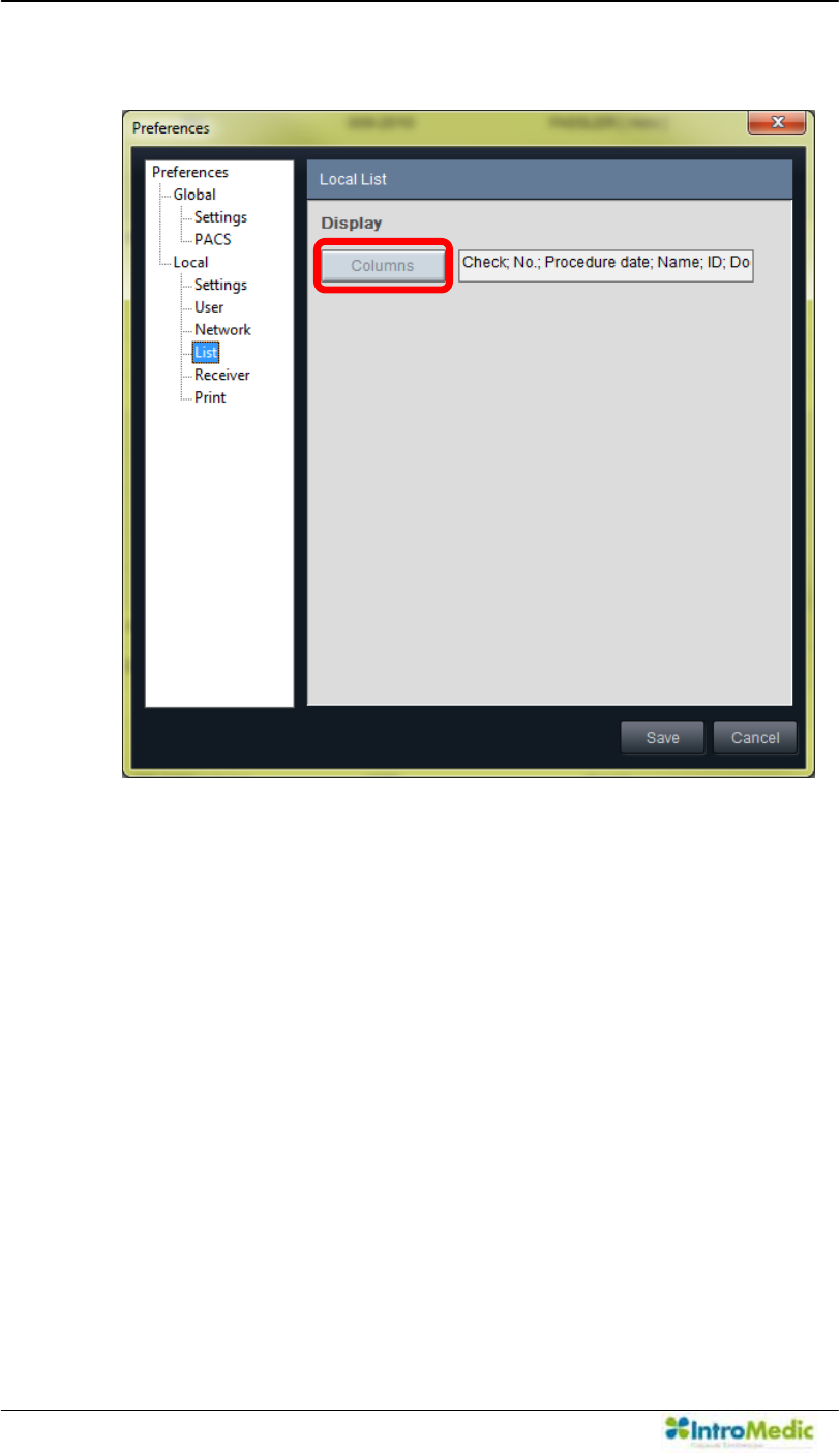
Using MiroView Software Chapter 4
4- 40
6) Local List
i. Display
Columns: Configure the columns which will appear on List.
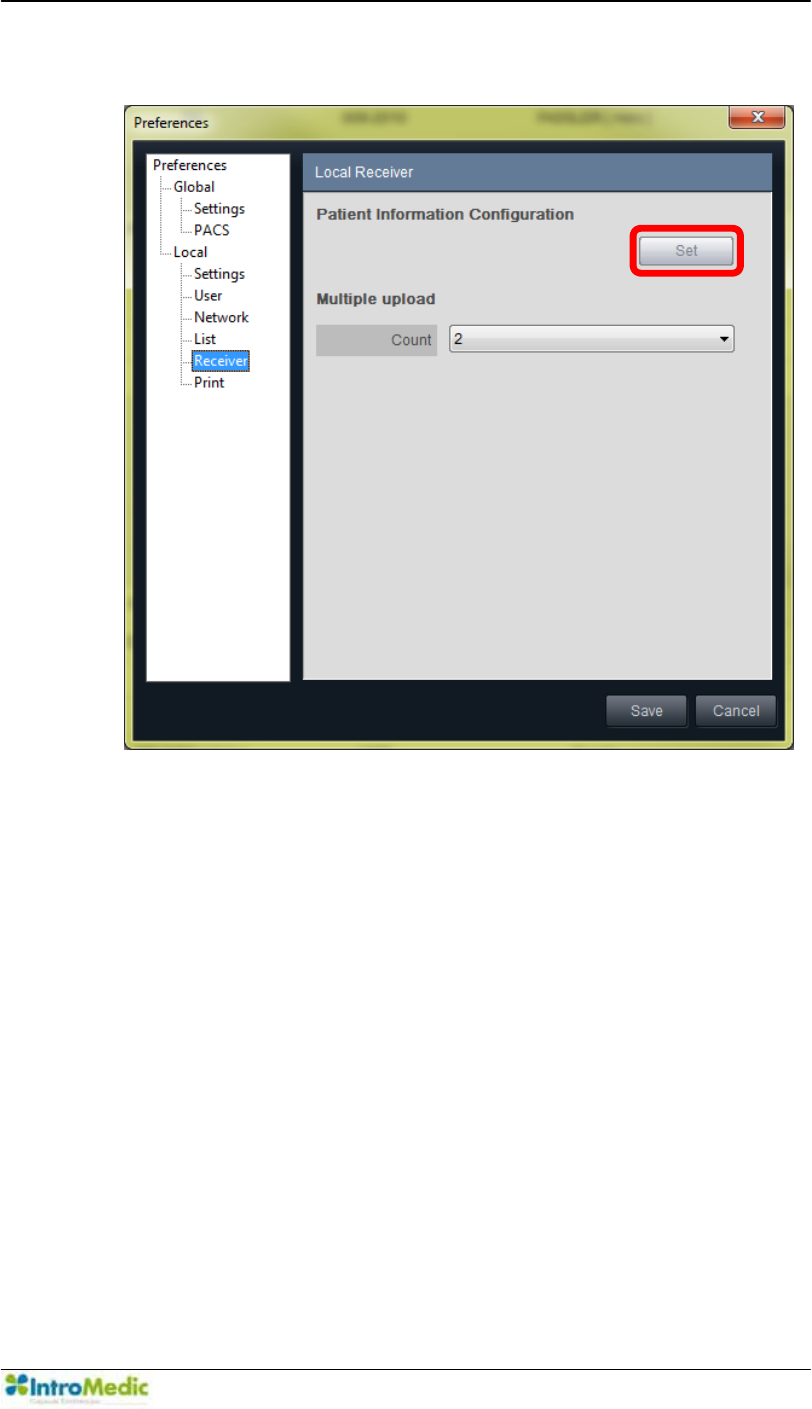
Chapter 4 Using 0LUR9LHZ Software
4-41
7) Local Receiver
i. Patient Information Configuration: Configure the items
shown on Patient Information after initializing the
MiroCam® Receiver.
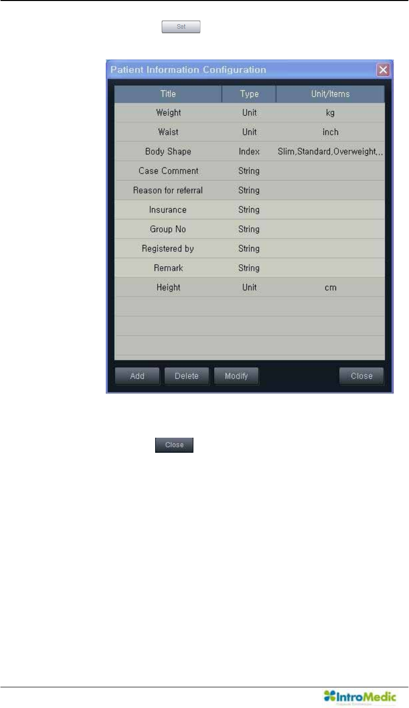
Using MiroView Software Chapter 4
4- 42
- Click the to show the Patient Information
Configuration window.
- Add/Delete/Modify the items. After completing the tasks,
click the to close the window.
ii. Multiple Upload
Count: Set the number of MiroCam® Receivers to upload
to the 0LUR9LHZOperator at once. Choose a number, 1
to 4.
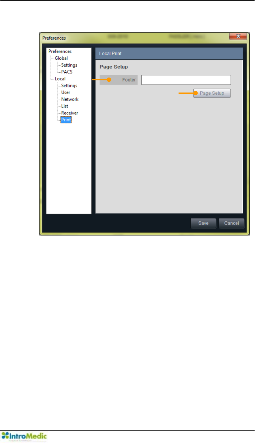
Chapter 4 Using 0LUR9LHZ Software
4-43
8) Local Print
i. Page Setup
ཛ Footer: Type in the string for footer which will appear on
the final report.
¤ Page Setup: Edit the layout of the report.
¢
£
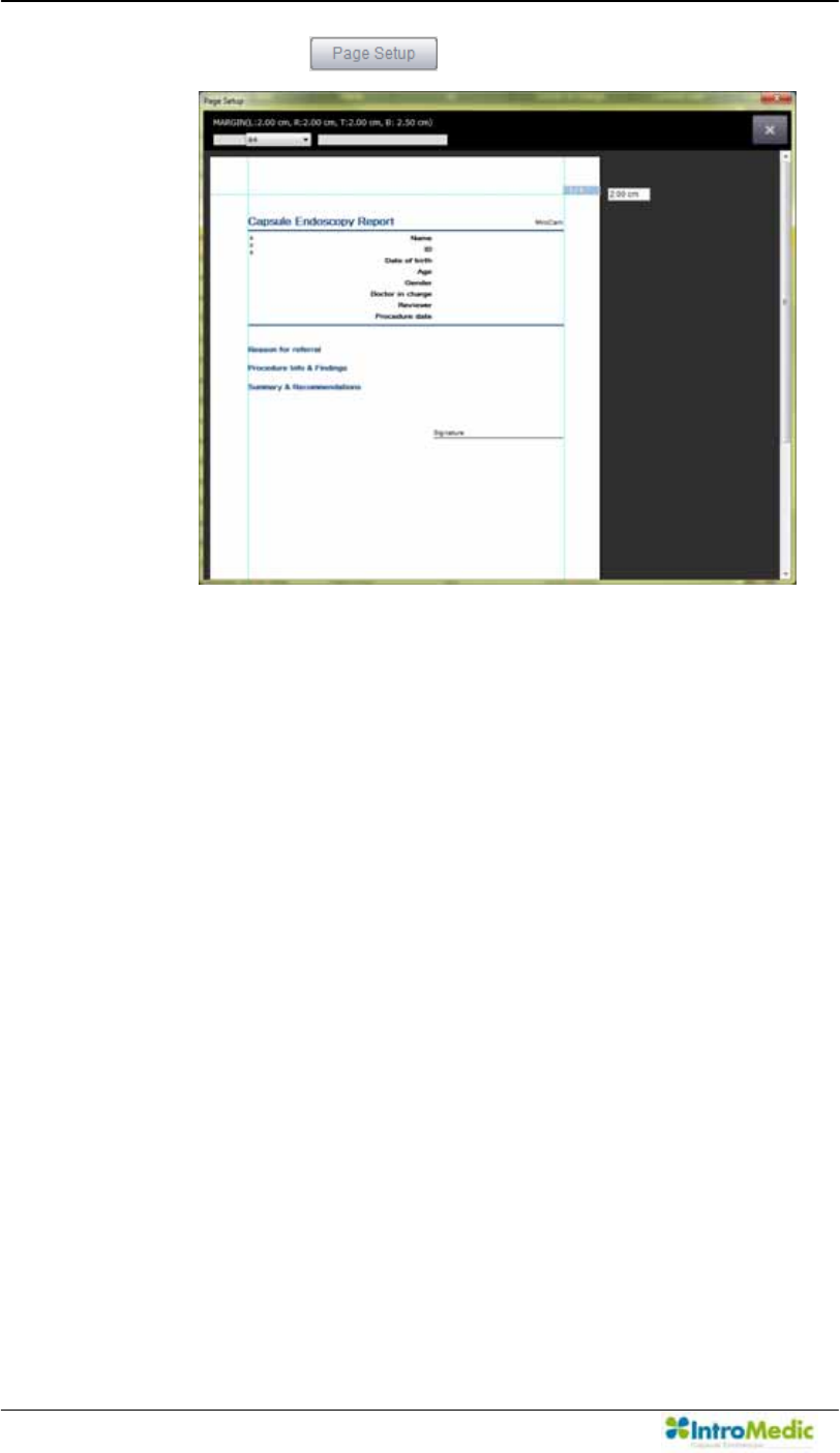
Using MiroView Software Chapter 4
4- 44
- Click the to show the Page Setup window.
- Choose the paper type; A4 or Letter and adjust the
margins for Header, Footer, Right and Left.
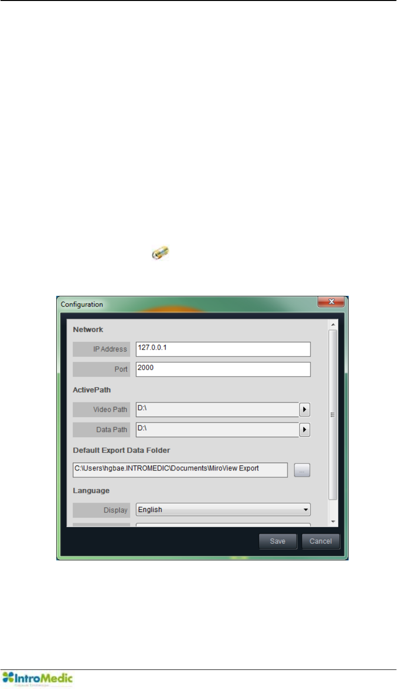
Chapter 4 Using 0LUR9LHZ Software
4-45
4.4 Overview - 0LUR9LHZClient
4.4.1 Start 0LUR9LHZClient
The 0LUR9LHZ Client is used to review images from the
MiroCam® Capsule procedure and generating a patient report.
2WKHU IXQFWLRQV LQFOXGHG ,Q 0LUR9LHZ &OLHQW DUH Network
Connectivity, List Mode, Review Mode, Report Mode, Export
Mode, Image Atlas, Multi-Review, SGIB(Suspected GI
Bleeding)Play, Express View, Range View, Map View, Positioning
Window, GI Dictionary, and Finding / Diagnosis Information.
Double-click the to run the 0LUR9LHZ Client. When
executed for the first time, the following window will appear.
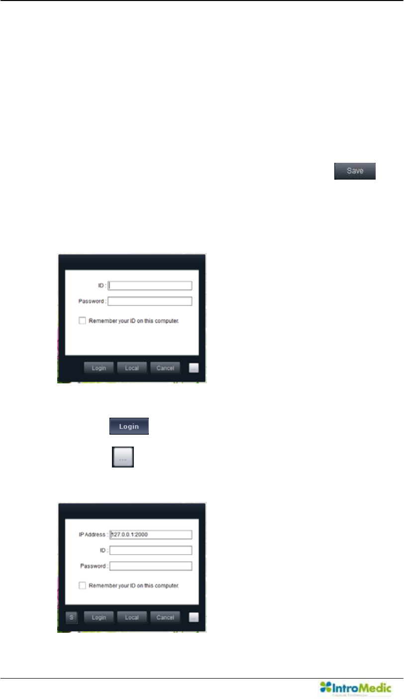
Using MiroView Software Chapter 4
4- 46
,QSXW³´IRUWKH,3$GGUHVVDQG³´IRUWKH3RUW
If the 0LUR9LHZ Server is installed on the network, input the
workstation¶V ,3 RQ ZKLFK WKH 0LUR9LHZ Server is installed for
this field, and the port which the 0LUR9LHZ Server is using,
referring to the IT engineer in the hospital.
'LUHFWWKH³Active Path´WRWKHFDFKLQJIROGer.
Direct the Default Export Data Folder.
Choose the preferred Language settings and press to
access the 0LUR9LHZClient.
After the 0LUR9LHZClient has launched, the Log-in window will
appear.
,QSXWµ$GPLQLVWUDWRU¶IRU,'DQGSDVVZRUGDOUHDG\W\SHGLQ7KHQ
press the .
Press the to change the IP address the 0LUR9LHZServer
is using.
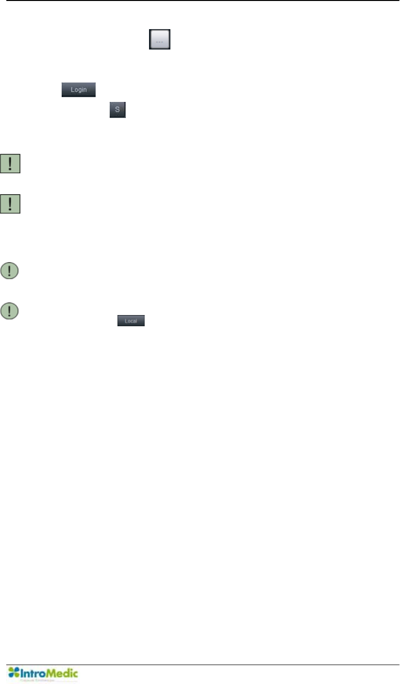
Chapter 4 Using 0LUR9LHZ Software
4-47
After clicking the the window will appear as the above. Type
the 0LUR9LHZ Server IP address and port. Then press the
after inputting ID and password.
(Use the to change the port number for the Server Manager,
which is used to manage the server availability)
CAUTION ID and password are encrypted. DO NOT forget the ID and
password.
CAUTION Before the 0LUR9LHZClient has launched, a password for
the administrator account should be created. When running
the 0LUR9LHZServer for the first time, a password for the
administrator account should be created.
NOTE Create new and edit new or existing accounts by using the
Account Management tool on the 0LUR9LHZOperator.
NOTE Access to the 0LUR9LHZ Client at Local Mode by clicking
the to use the 0LUR9LHZClient without connecting
to the 0LUR9LHZServer.
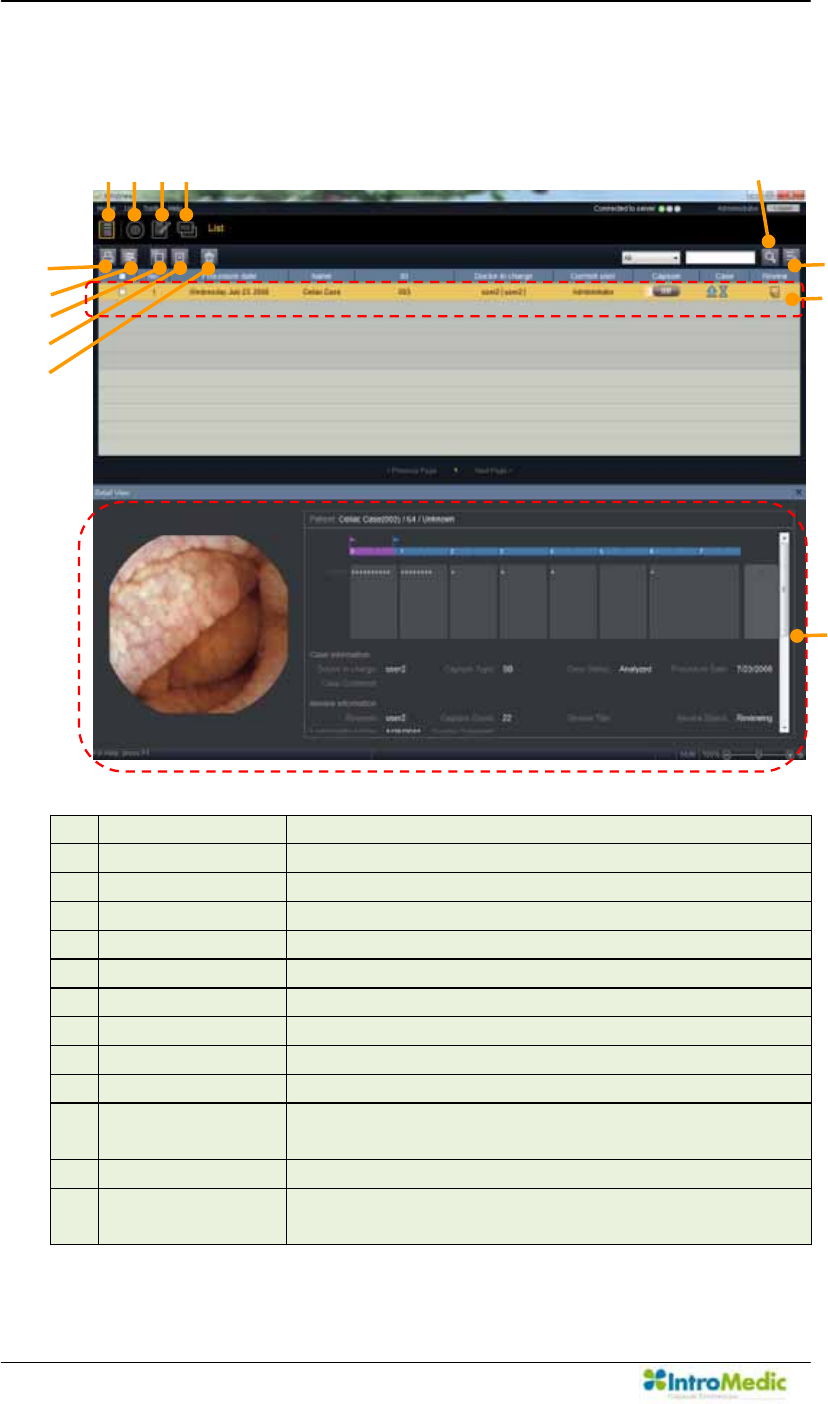
Using MiroView Software Chapter 4
4- 48
4.4.2 List Mode
List
£ List Mode Open List Mode
¤ Review Mode Open Review Mode
¥ Report Mode Open Report Mode
¦ Export Mode Open Export Mode
§ Print Report Print selected Report
¨ Delete Case Delete Selected Case
© Add a Review Add a Review for the Selected Case
ª Delete Review Delete selected Review
« Recycle Bin Open Recycle Bin
¬ Search Search Cases and/or Reviews by key word
Show all Refresh and Show all the Cases/Reviews on the
List
® Selection Bar A rectangular area to show selected item
¯ Detail View Show Detail Information for selected Case or
Review
c
d
e
f
g
h
i
j
k
l
̺
11
̺
12
̺
13
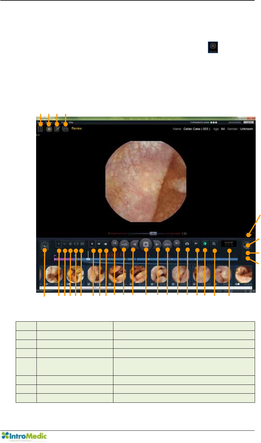
Chapter 4 Using 0LUR9LHZ Software
4-49
4.4.3 Review Mode
Select a case to review on the List Mode and click the to enter
the Review Mode.
Capture Box Mode
£ List Mode Open List Mode
¤ Review Mode Open Review Mode
¥ Report Mode Open Report Mode
¦ Export Mode Open Export Mode
§ Position Window Current position of the
MiroCam® Capsule in 2D
¨ Single View Change to Single View
© Dual View Change to Dual View
ª Quad View Change to Quad View
c
d
e
f
̺
5
̺
6
̺
7
̺
8
̺
9
̺
10
̺
11
̺
12
̺
13
̺
14
̺
15
̺
16
̺
17
̺
18
̺
19
̺
20
̺
21
̺
22
̺
23
̺
24
̺
26
̺
27
̺
25
̺
28
̺
29

Using MiroView Software Chapter 4
4- 50
« Range View Change to Range View
¬ Map View Change to Map View
Normal Play Show all images.
® Express Play This mode actively removes images
based upon similarity; effectively
reducing the number of images for
review. This mode is recommended to
review the patient file but not to diagnose
the patient symptoms.
¯ SGIB Play Shows the images that have a high
possibility of bleeding and / or blood. This
mode may assist in finding areas of
suspected bleeding; however, it is NOT
100% reliable, and should only be used
as an adjunctive tool to assist in
reviewing the images.
° First Frame Go to the First Image Frame
± Previous Captured
Image
Go to Previous Captured Image Frame
ԧ Play in reverse Play in reverse
Ԩ Play / Pause Play / Pause
ԩ Play Play Forward
Ԫ Next Captured Image Go to the Next Captured Image
ԫ Last Frame Go to the final Image Frame
Capture Image Image capture button.
Set landmark Landmark button. Use this to set
landmarks for transition points in the GI
tract.
Image Enhancement Show the Image Enhancement window
Full Screen Mode Fit image to full screen
Time Display Display the time duration of the
MiroCam® Capsule from procedure start.
Annotation Box
Handle
Expand / Shrink the control panel
(Show / Hide the Capture Box)
The video image area may widen by
Annotation Box Handle.
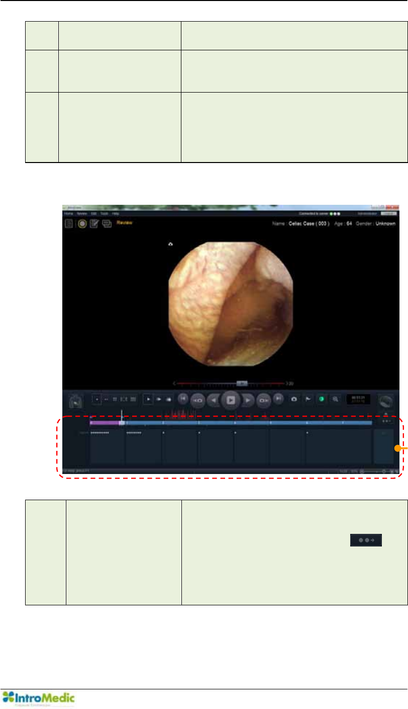
Chapter 4 Using 0LUR9LHZ Software
4-51
Comparison Window Display the image selected from the
Image Atlas
Thumbnail Extension Extend the Capture Box to display all
captured images.
(Hide the Video area)
Capture Box /
Finding Summary
Box / Drag Bag
Toggle Icon
Replace the Capture Box with Finding
Summary Box or Drag Bag.
Finding Summary Box
Finding Summary
Box
Displays Capture Box, Thumbnail and
Finding Summary Box.
This is changed by clicking the .
When new findings are added in Report
mode, new information for captured
image will be shown in Finding Summary
Box.
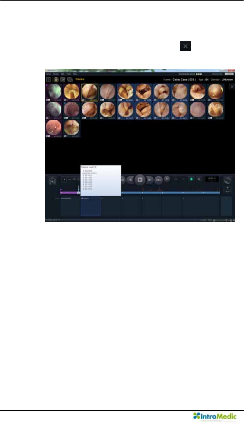
Using MiroView Software Chapter 4
4- 52
- Choose a section of Summary Box to show the thumbnails.
When a section of Summary Box is selected, the thumbnails
will be shown in the screen. Click the to close the
thumbnail mode.
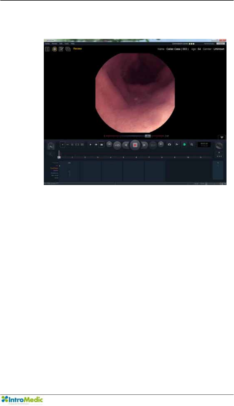
Chapter 4 Using 0LUR9LHZ Software
4-53
Drag Bag
- Choose a section of Drag Bag to show the captured images.
- There are two ways to set the captured image, the drag bag:
set the main image to a drag directly and capture the main
image first and set the image to a drag bag via the pop-up
menu.
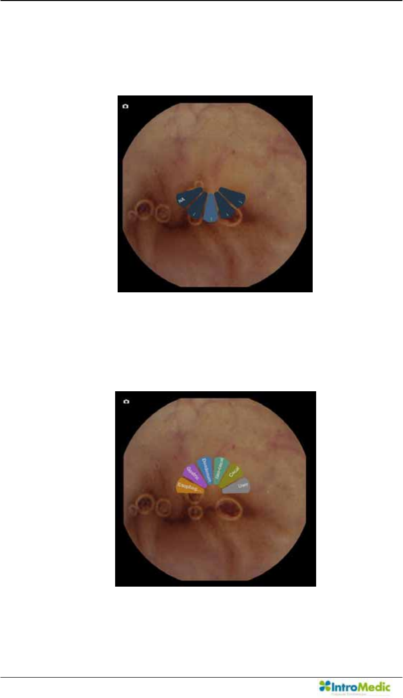
Using MiroView Software Chapter 4
4- 54
i. Left click the mouse and drag the mouse downwards.
Fan shaped Drag Bags will appear like below.
Release the mouse in one of them.
ii. Left click the mouse and drag to upper direction. Fan
shapes for Landmarks will appear like below. Release
the mouse on one of them.
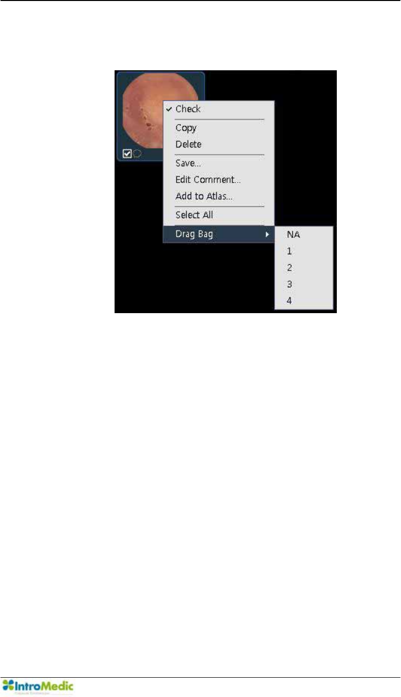
Chapter 4 Using 0LUR9LHZ Software
4-55
iii. Right click the mouse on a captured image and then
set the image to a Drag Bag.
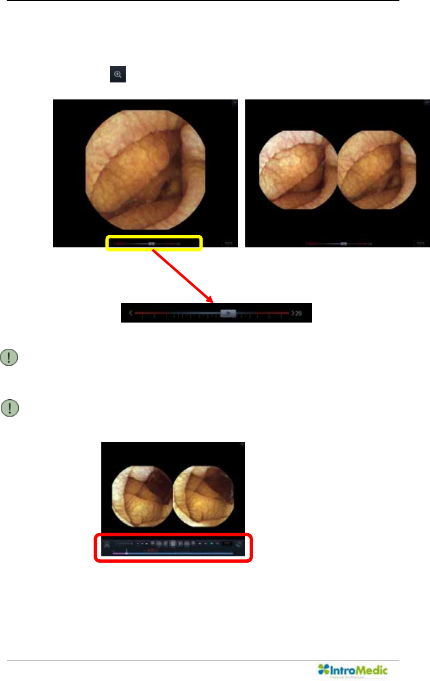
Using MiroView Software Chapter 4
4- 56
Mode Control
- Full Screen Mode
Click the to change to Zoom View mode
NOTE Play Slide Control is available on the Full Screen
Mode to set playing direction, playing speed and
playing status: Play and Pause.
NOTE Move the cursor away from the bottom of the
screen and the Play Control will appear.
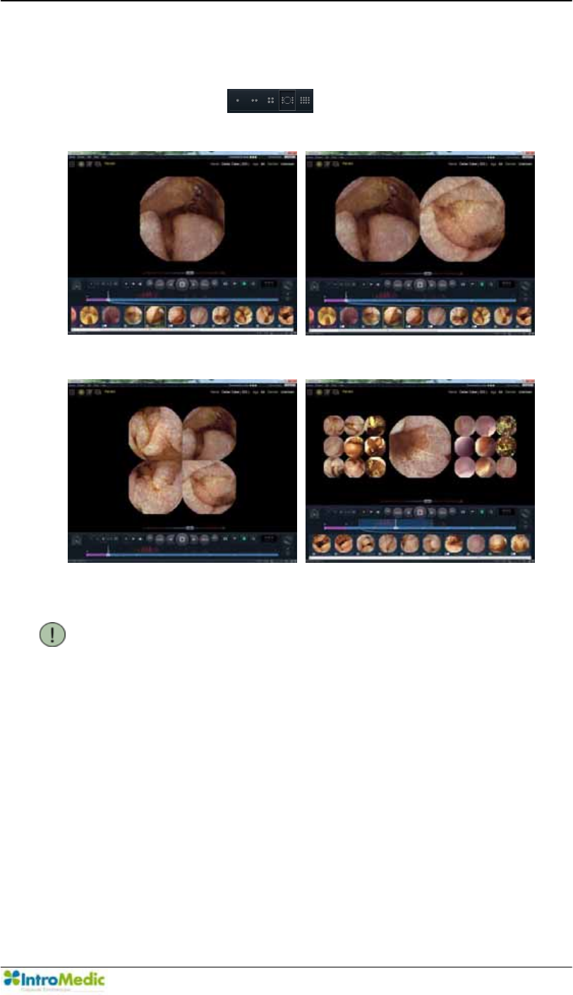
Chapter 4 Using 0LUR9LHZ Software
4-57
- Viewing Modes
Select one of the for preferred Viewing
Mode.
Single View Dual View
Quad View Range View
NOTE Range View has been designed to assist in readily
finding transition points in the GI tract. The display
will show 9 images before and 9 images after the
current position. The 9 images are defaulted to 10
minutes apart, resulting in an overview of 90
minutes prior to, and 90 minutes after the current
position. The number of images displayed is set at
9, and is not configurable. The 90 minute duration
is configurable and can be adjusted by dragging
the side line in blue on the Time Bar and dragging
the mouse icon on the time boundary. It can also
be adjusted by going to Tools -> Preference ->
Review.
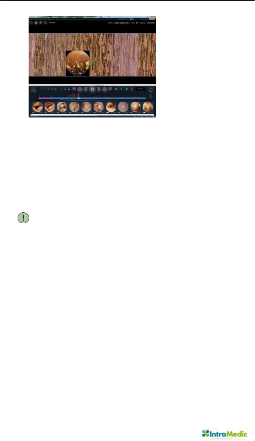
Using MiroView Software Chapter 4
4- 58
Map View
- Use the wheel of the mouse to zoom in/out the map.
- Double-click the desired image to capture. Right click the mouse for
the desirable image to capture or set landmark.
- Click the desirable image and press <Space> to play the adjacent
image frames.
NOTE Map view has been designed to assist in reviewing
the patient file by showing all the images on the
same page to assist in readily identifying
landmakers and potential bleeding areas.
Move the cursor on the designated image to see
the original image in detail.
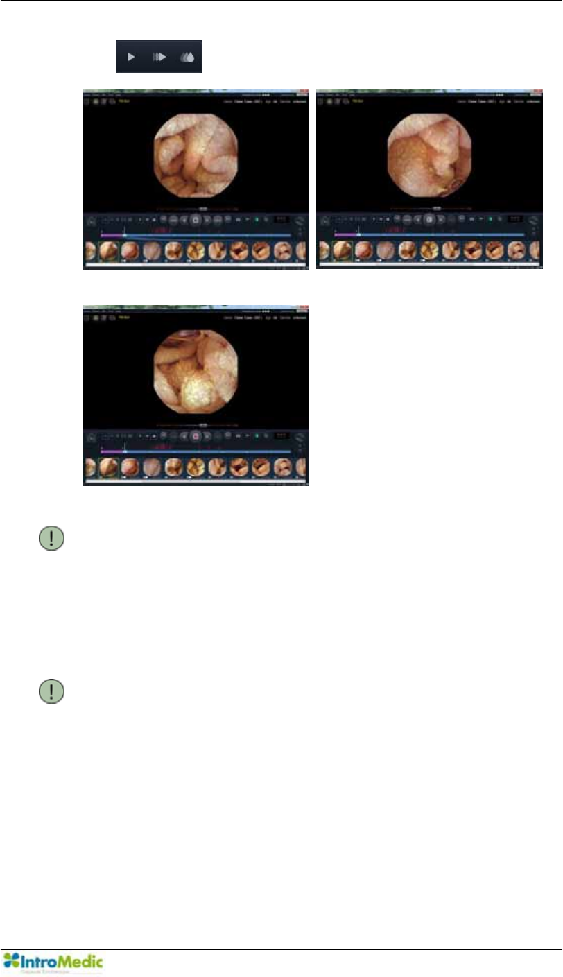
Chapter 4 Using 0LUR9LHZ Software
4-59
- The will change to playing Mode, as below.
Normal Play Express Play
SGIB Play
NOTE The Express Play shows the meaningful images
only so that the user can review the whole video
for the patient quickly. When entering the Express
Play, the 0LUR9LHZ Software will show the
message, The Express Play is not intended to
detect abnormalities and should not be used as a
substitute for reviewing the entire video.
NOTE The SGIB Play shows the images in red or the
obscure bleeding images. IntroMedic does not
guarantee the performance and/or accuracy. Thus,
use this function for reference only.
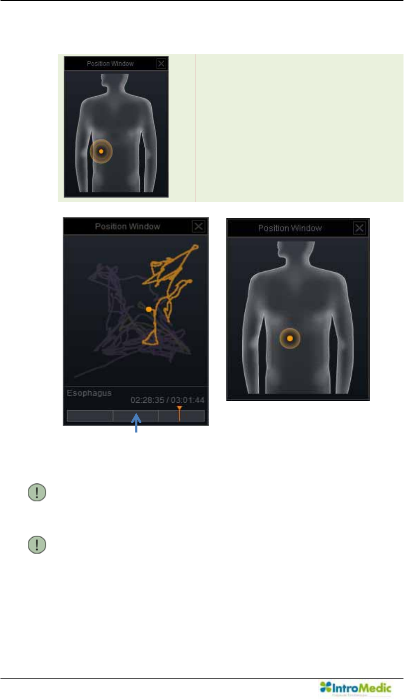
Using MiroView Software Chapter 4
4- 60
Position Window
NOTE User is able to choose the option of selecting the
type of Position Window between line and region.
NOTE User is able to change the Position Window
Setting via Tools -> Preference
Divides the body into 8 areas and
displays the location of where the
MiroCam® Capsule took the current
image.
Organ Bar
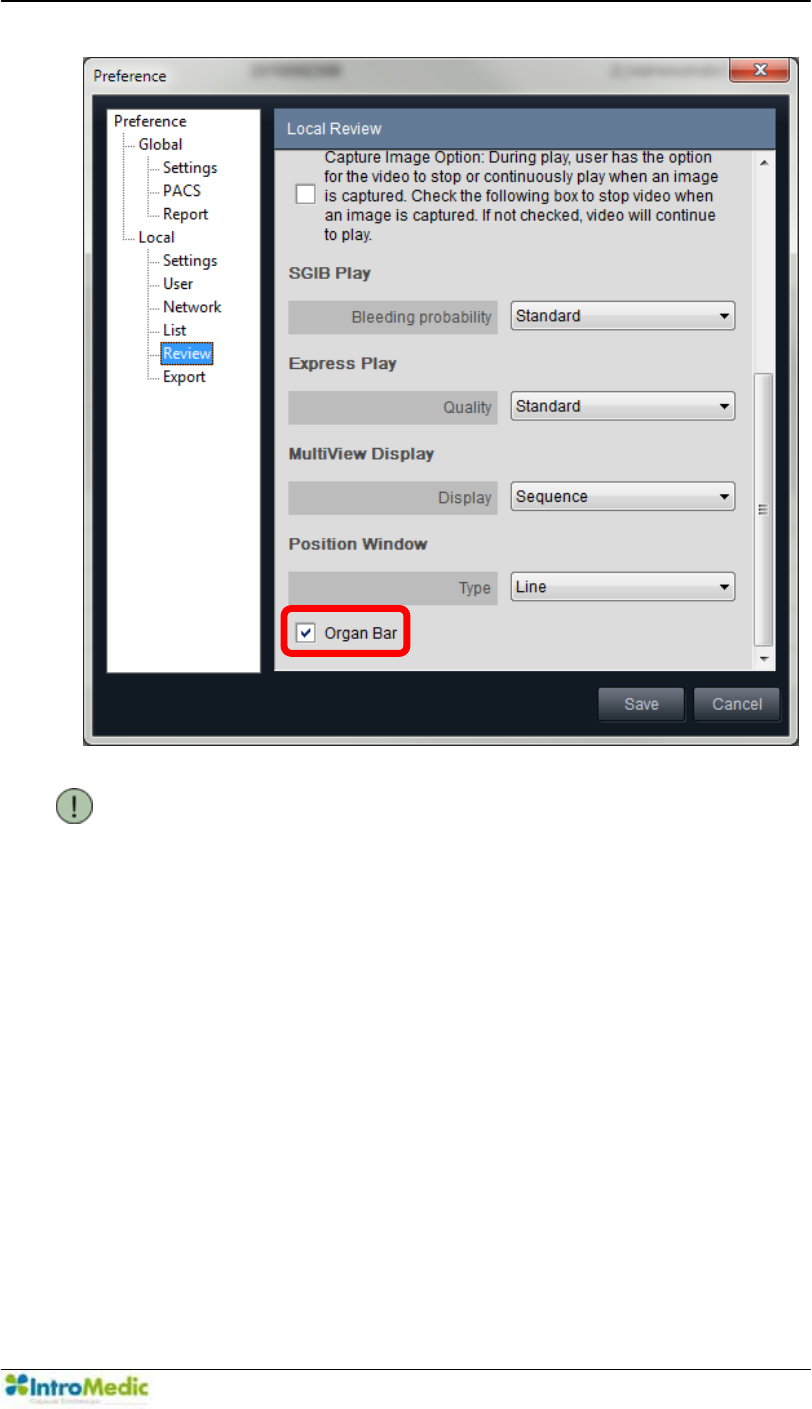
Chapter 4 Using 0LUR9LHZ Software
4-61
NOTE User can now choose the Organ bar option. This
organ bar also displays the entire trajectory of the
MiroCam® Capsule in the GI track.
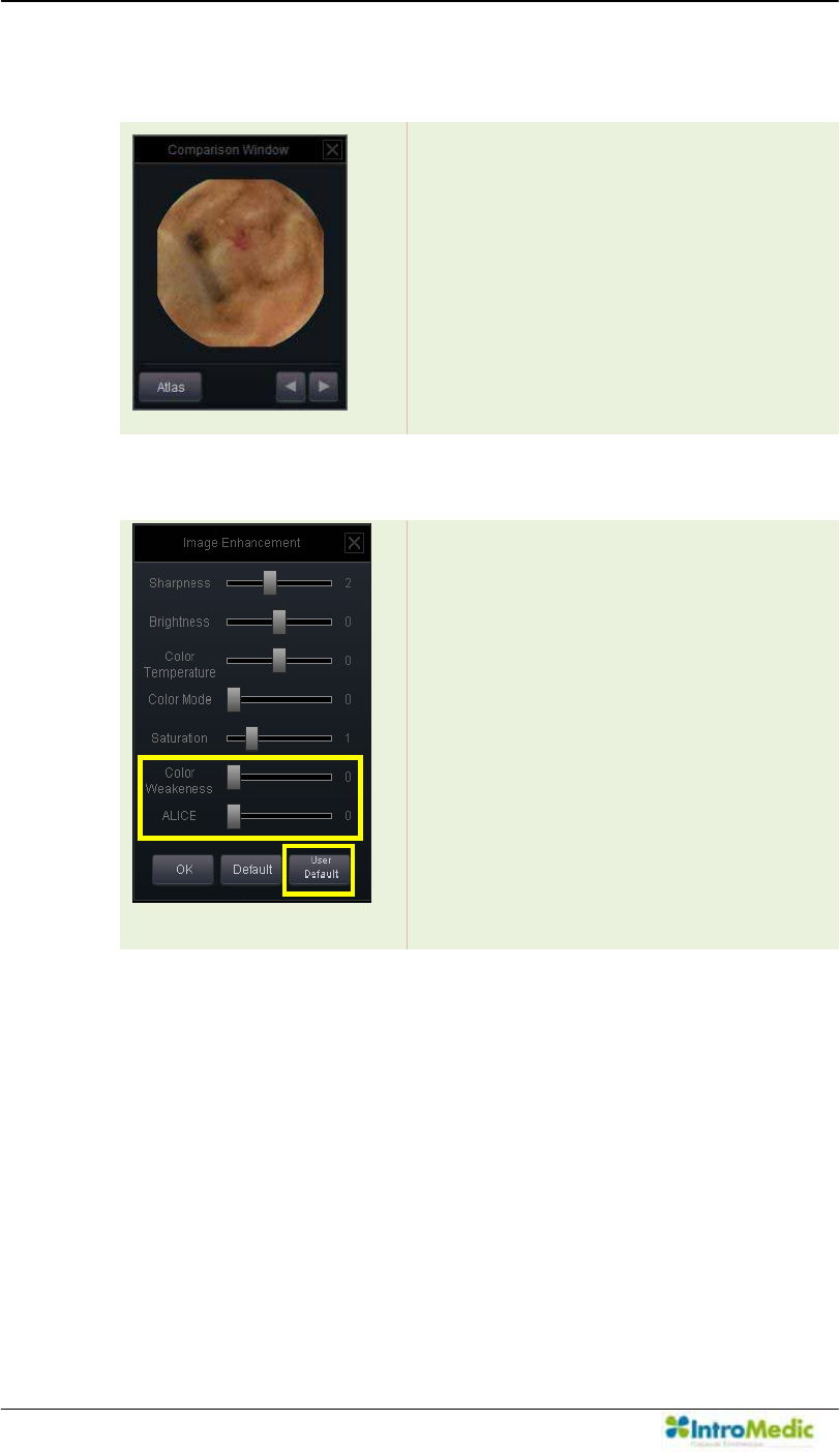
Using MiroView Software Chapter 4
4- 62
Comparison Window
Displays the image shown from the
Image Atlas lastly.
Image Enhancement Window
Alter images characteristics (ie. color,
saturation etc.) to assist in identifying
abnormalities:
- Color Weakness
: Image adjustment for the
reviewer who has color
blindness.
- ALICE
: Image adjustment as
NBI(Narrow Band Image)
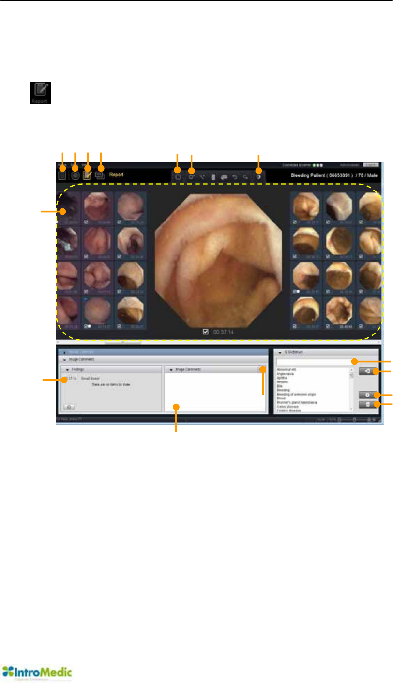
Chapter 4 Using 0LUR9LHZ Software
4-63
4.4.4 Report Mode
Select the desired review for the Case from the List Mode and click the
to move to the Report Mode.
Report Mode
̺
1 ̺
2 ̺
3 ̺
4 ̺
5 ¨
̺
7
ྣ
̺
12
̺
13
̺
14
̺
15
̺
8
«
¬

Using MiroView Software Chapter 4
4- 64
£ List Mode Open List Mode
¤ Review Mode Open Review Mode
¥ Report Mode Open Report Mode
¦ Export Mode Open Export Mode
§ Circumference
markers
Opens graduated scale for display on
the image
¨ Drawing Tools Enables users to include annotations for
the image.
© Image Enhancement Alter images characteristics (ie. color,
saturation etc.) to assist in identifying
abnormalities.
ª Thumbnail Area Show the adjacent captured images
so that the user can select/deselect
the captured images to export.
« Image Comments Write comments for the Capture on the
main display and the report.
(Image Comments, Reason for Referral,
Procedure info & findings, Summary &
Recommendation)
¬ Diagnosis Provides the Level of certainty of
diagnosis.
Audio Comment Record voice comment
(The user can record the voice, from 3
seconds to 180 seconds for each
captured image)
® GI Dictionary Provides the frequently-used-words to
search.
¯ Input Selected Word Input the selected word into the text
editor.
° Add Word to
Dictionary
Add the typed word into the Dictionary.
± Remove word from
Dictionary
Delete selected word from the
Dictionary.
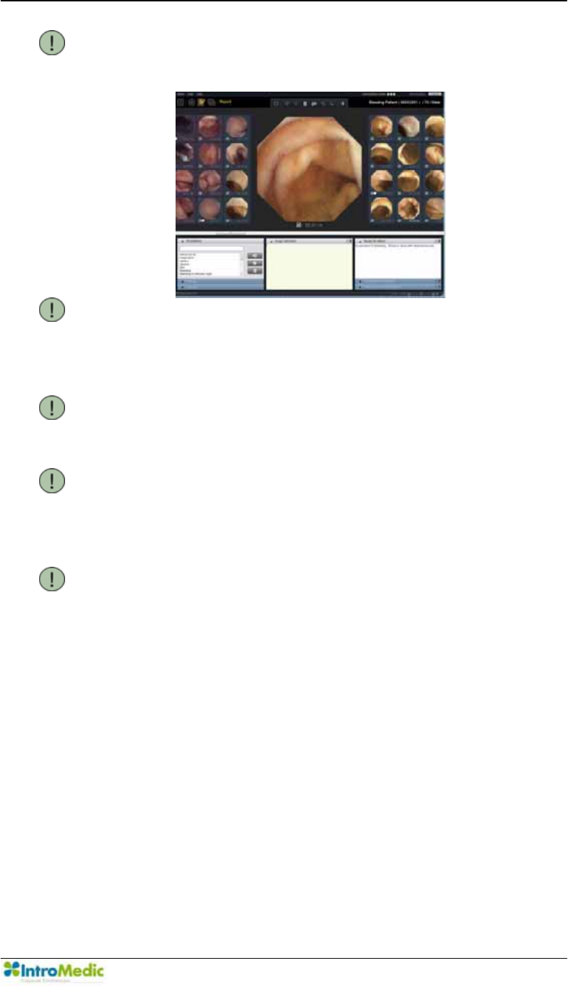
Chapter 4 Using 0LUR9LHZ Software
4-65
NOTE User is able to change the Panel Layout like
following pictures via Tools -> Preference -> Local
-> Report
NOTE Comments can be completed automatically by
pressing <Ctrl+ Space Bar> or <Ctrl + Enter> on
the keyboard.
Refer to 4.6.4 5HYLHZ 0LUR9LHZ &OLHQW for
more information.
NOTE Additional tabs in the report can be created or
modified via Tools -> Preferences -> Report
NOTE Right click the mouse on Text Comments area to
use Annotations.
Refer to 4.6.4 5HYLHZ 0LUR9LHZ &OLHQW for
more information.
NOTE Patient information, including the reason for
referral, is registered in the MiroCam® Receiver
via 0LUR9LHZ2SHUDWRU
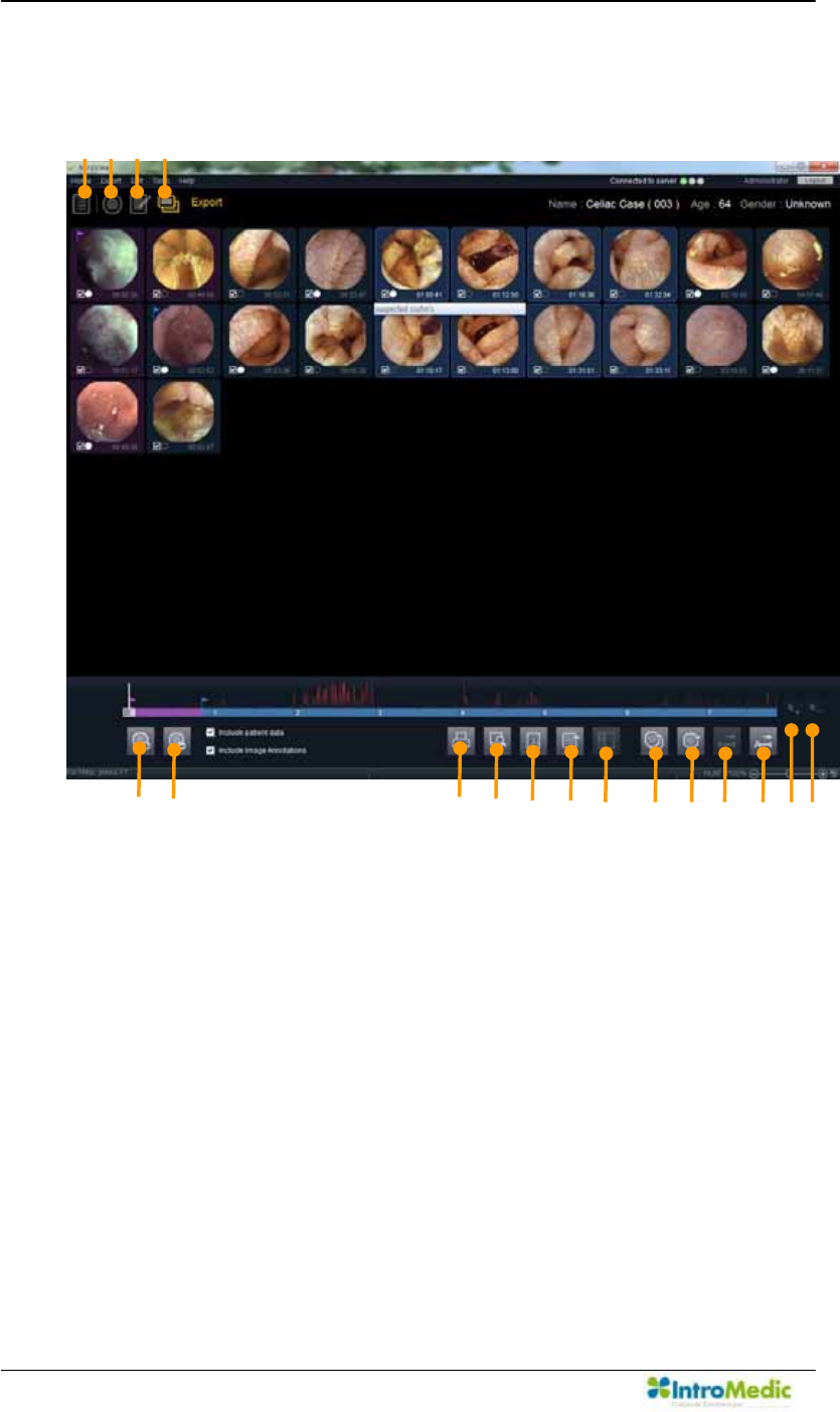
Using MiroView Software Chapter 4
4- 66
4.4.5 Export Mode
̺
1 ̺
2 ̺
3 ̺
4
g h ̺
7 ̺
8
̺
9
̺
10 ̺
11 ̺
12 ̺
13 ̺
14 ̺
15 ̺
16 ̺
17

Chapter 4 Using 0LUR9LHZ Software
4-67
£ List Mode Open List Mode
¤ Review Mode Open Review Mode
¥ Report Mode Open Report Mode
¦ Export Mode Open Export Mode
§ Check
Captured
Image
Select Captured image and add to the list to
print/export.
¨ Uncheck
Captured
Image
Deselect Captured image and remove from the
candidate list to print/export.
© Print Print out the report for the Review.
ª Preview Preview the report
« Save as PDF Save the report as a PDF file.
¬ Export Review Export Review data only without the Video.
Review data is the own format of the
0LUR9LHZ Software, which contains Captured
Images and Comments by the user.
Send to PACS Send selected captured images to PACS system
via DICOM Sender
® Export EXMIF Export Captured Images as EXMIF
EXchangeable Medical Information Format)
¯ Export Images Export Captured Images as Image, Video, or
MiroVideo. MiroVideo is the own video format for
the 0LUR9LHZ Software.
° Export
Segment
Export segment as Video, MiroVideo
± Export Entire Export entire file as Video, MiroVideo
ԧ Add segments Add the selected range as segments
Ԩ Remove
segments
Remove the selected range from segments.
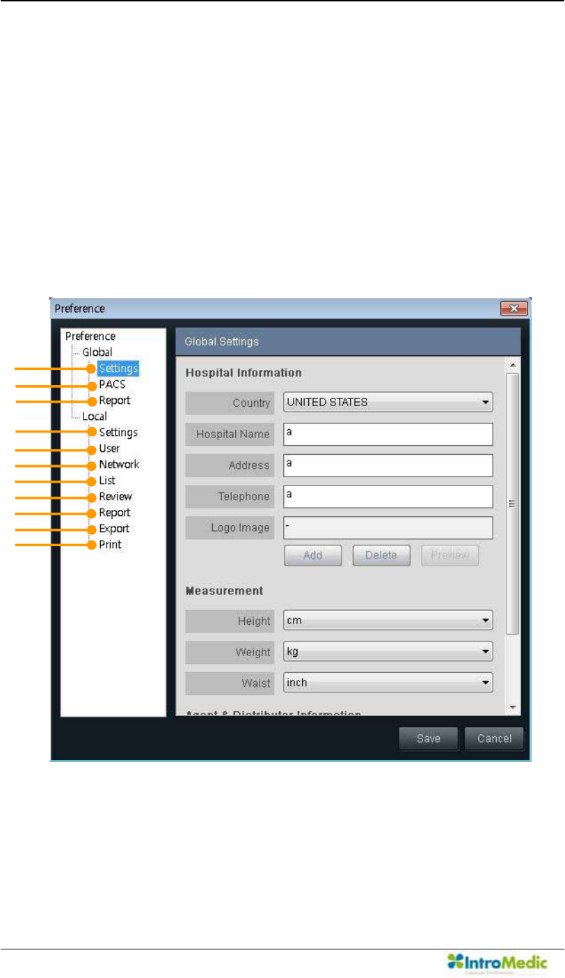
Using MiroView Software Chapter 4
4- 68
4.4.6 Preferences
Preferences for the 0LUR9LHZ Client falls into two categories:
Global and Local.
Global preference is saved on the 0LUR9LHZ Server and has in
effect for all the users using the 0LUR9LHZServer.
Local preference is saved on the workstation on which the
0LUR9LHZ Client is installed and has in effect for the workstation
only.
¢
£
¤
¥
¦
§
¨
©
ª
«
¬

Chapter 4 Using 0LUR9LHZ Software
4-69
Global £ Settings - Hospital Information
- Measurement
- Agent & Distributor Information
¤ PACS - PACS Registration
- Technical Settings
¥ Report - User added comment tab
Local ¦ Settings - Language
- GI Tract Color Reference
- Captured Image Box
- Free Hard Disk
- Display
- Default Export Data Folder
- Auto Recover Information
- Finding Setting
§ User - 8VHU¶V,QIRUPDWLRQ
- Change Password
¨ Network - 0LUR9LHZServer
- Server Manager
© List - Display ± Show/Hide Columns
ª Review - Range View
- Summary Control
- Capture
- Captured Image Box
- Drag Bag
- SGIB Play
- Express Play
- Position Window
« Report - Panel Layout
¬ Export - Export AVI (captured images)
Print - Page Setup
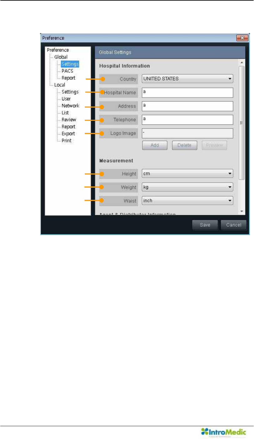
Using MiroView Software Chapter 4
4- 70
1) Global Settings
i. Hospital Information
ཛ Country ± Choose the Country where the hospital is located.
ཛྷ Hospital Name ± ,QSXWWKH+RVSLWDO¶V1DPHLQ this field.
ཝ Address ± ,QSXWWKH+RVSLWDO¶V$GGUHVVLQWKLVILHOG
ཞ Telephone ± ,QSXWWKH+RVSLWDO¶V7HOHSKRQHQXPEHULQWKLV
field.
ཟ Logo Image ± Add the Logo Image
These information will be applied and shown on the final
report.
§
¨
©
¢
£
¤
¥
¦
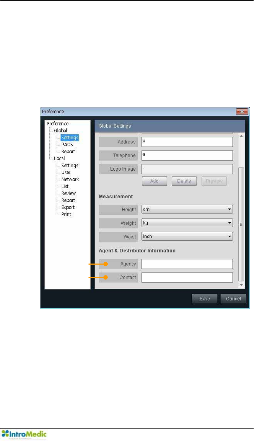
Chapter 4 Using 0LUR9LHZ Software
4-71
ii. Measurement
འ Height ± &KRRVHWKHPHDVXUHPHQWXQLWIRUSDWLHQW¶VKHLJKW
ཡ Weight - &KRRVHWKHPHDVXUHPHQWXQLWIRUSDWLHQW¶VZHLJKW
ར Waist - &KRRVHWKHPHDVXUHPHQWXQLWIRUSDWLHQW¶VZDLVW
These information will be applied and shown on the case
information and patient information
iii. Agent & Distributor Information
ལ $JHQF\,QSXWWKH$JHQF\¶VLQIRUPDWLRQLQWKLVILHOG
ཤ Contact: Input the contact information for the agency.
ª
«
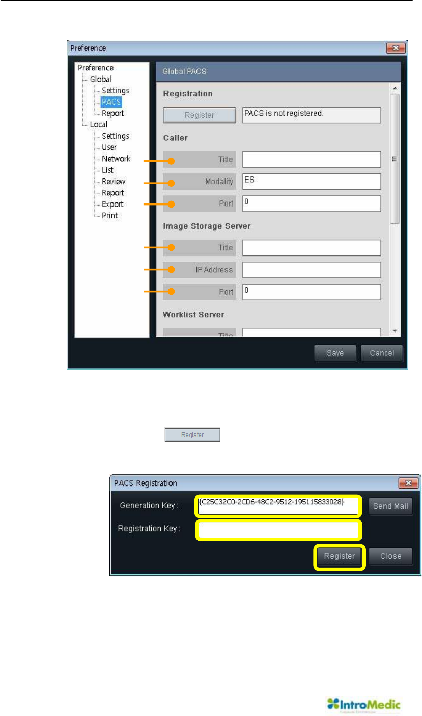
Using MiroView Software Chapter 4
4- 72
2) Global PACS
i. Registration: Process to enable the PACS related
functionalities.
- Click the . PACS registration window will
appear like below.
¢
¤
£
¥
¦
§
§
¦
¥
¢
£
¤
Ú
Û
Ü
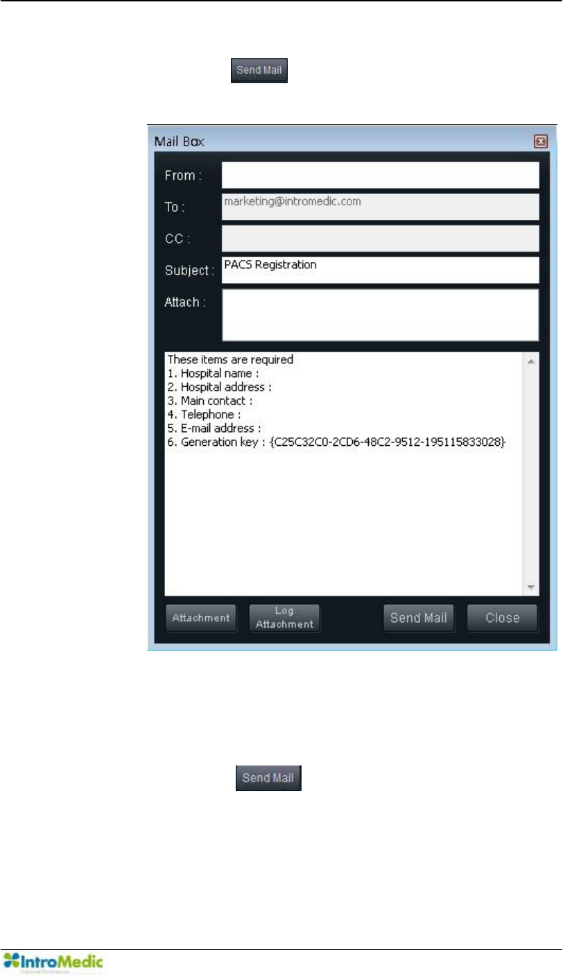
Chapter 4 Using 0LUR9LHZ Software
4-73
- Generation key will be generated automatically.
Click the to send the generation key to
IntroMedic. Mail Box window will appear like below.
- Input the e-PDLODGGUHVVLQWKHILHOGµ)URP¶for receiving
the Registration Key. Fill in the information for the items
in the text box: Hospital name, Hospital address, Main
contact, Telephone, E-mail address and Generation key.
- Click the to send the information to
IntroMedic. IntroMedic will reply with the Registration
Key to the e-PDLO DGGUHVV W\SHG LQ µ)URP¶ ILHOG ,W ZLOO
take time to receive the reply.

Using MiroView Software Chapter 4
4- 74
- Click the to close the Mail Box window.
- After receiving the Registration Key, input the Key in the
Registration Key field on PACS registration window.
Click the to finalize the registration process.
ii. Caller: Technical properties for Caller.
ཛ Title: Input the Title for Caller.
ཛྷ Modality: Input the Modality for Caller.
ཝ Port: Input the port number to use for Caller.
iii. Image Storage Server: Technical properties for Image
Storage.
ཞ Title: Input the title for Image Storage Server.
ཟ IP Address: Input the IP Address for Image Storage Server.
འ Port: Input the port number to connect to Image Storage
Server.
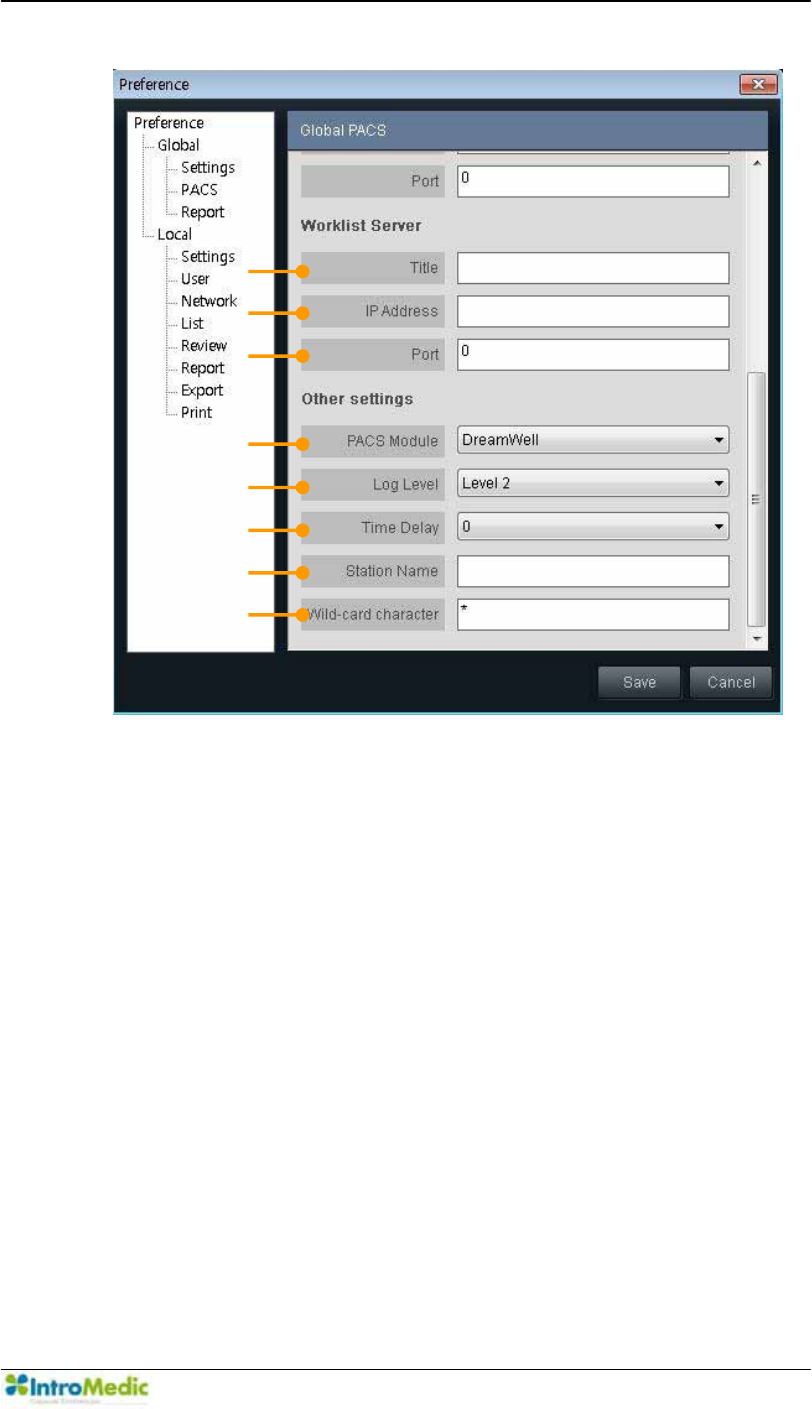
Chapter 4 Using 0LUR9LHZ Software
4-75
iv. Worklist Server: Technical property for Worklist Server.
ཡ Title: Input the Title for Worklist Server.
ར IP Address: Input the IP Address for Worklist Server.
ལ Port: Input the port number to connect to Worklist Server.
v. Other Settings: Technical properties for PACS setting.
ཤ PACS Module: Choose the appropriate PACS Module of
DreamWell or Vieworks.
ཥ Log Level: Choose the appropriate Log Level for the PACS
functionality: Level 0, Level 1 and Level 2.
ས Time Delay: Choose the Time delay from 0 to 9 seconds.
ཧ Station Name
ཨ Wild-card character
¯
®
¬
ª
©
¨
«
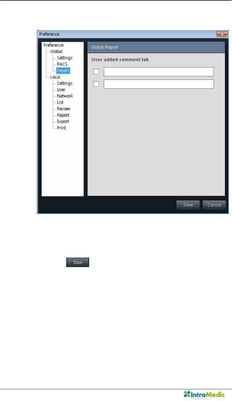
Using MiroView Software Chapter 4
4- 76
3) Global Report
i. User added comment tab: If checking on the checkbox and
typing the desired string into the textbox, a comment tab
will be added on the Report Mode. To apply the change,
click .
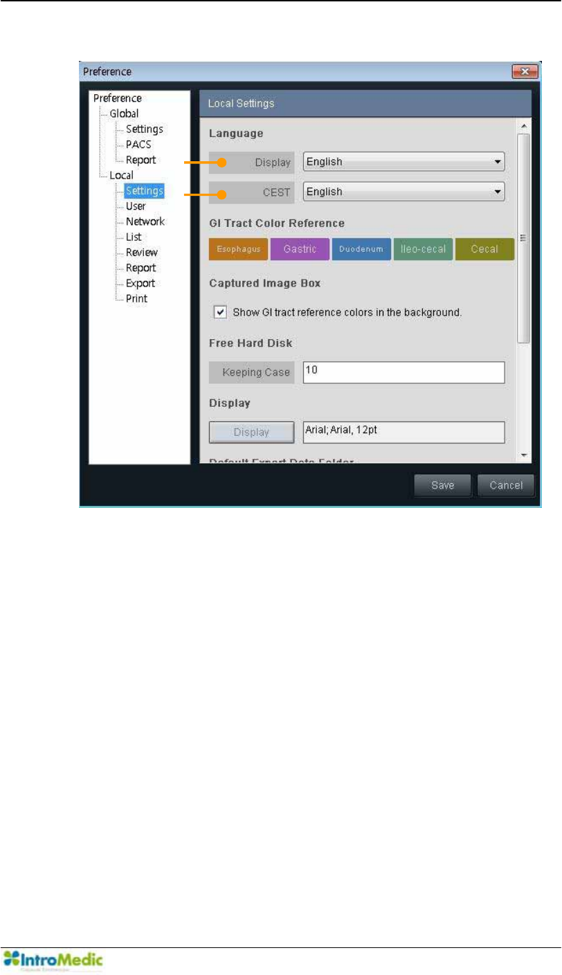
Chapter 4 Using 0LUR9LHZ Software
4-77
4) Local Settings
i. Language
ཛ Display: Choose the display language.
ཛྷ CEST: Choose the CEST language.
ཝ GI Tract Color Reference: Show the color references for
the GI Tract.
ii. Captured Image Box: Check the check box to show GI tract
reference colors in the background of Captured Image Box.
¢
£
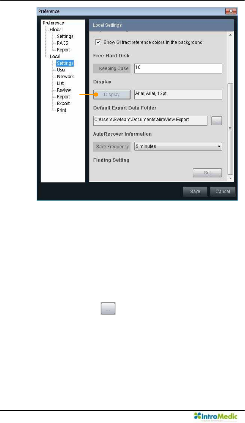
Using MiroView Software Chapter 4
4- 78
iii. Free Hard Disk
Keep the number of cases on the local drive. If the cases
are cached from the Server more than the configured
number, the oldest case on the local drive will be freed up.
iv. Display
Display: Font setting to display.
v. Default Export Data Folder: Direct the folder for exporting
data. Click the to open the browser.
vi. AutoRecover Information
Save Frequency: The 0LUR9LHZ Client saves the auto
recovery information while the user is reviewing the patient
file, periodically. Choose the period to save the auto
recovery information from 0 to 60 minutes.
¤
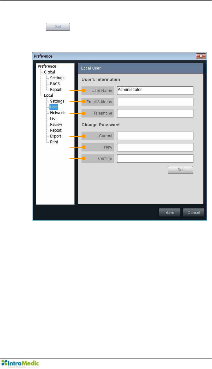
Chapter 4 Using 0LUR9LHZ Software
4-79
vii. Finding Setting: Configure the finding setting. Click the
to open the configuration dialogue.
5) Local User
i. 8VHU¶V,QIRUPDWLRQ6HWPRGLI\WKHLQIRUPDWLRQIRUWKHXVHU
ཛ User Name: Input User Name which will be used for log-in
ID.
ཛྷ Email Address: Type in the e-mail address here.
ཝ Telephone: Type in the telephone number here.
ii. Change Password
ཞ Current: Input the current password
ཟ New: Input the desired password to use.
འ Confirm: Input the desired password again.
¢
£
¤
¥
¦
§
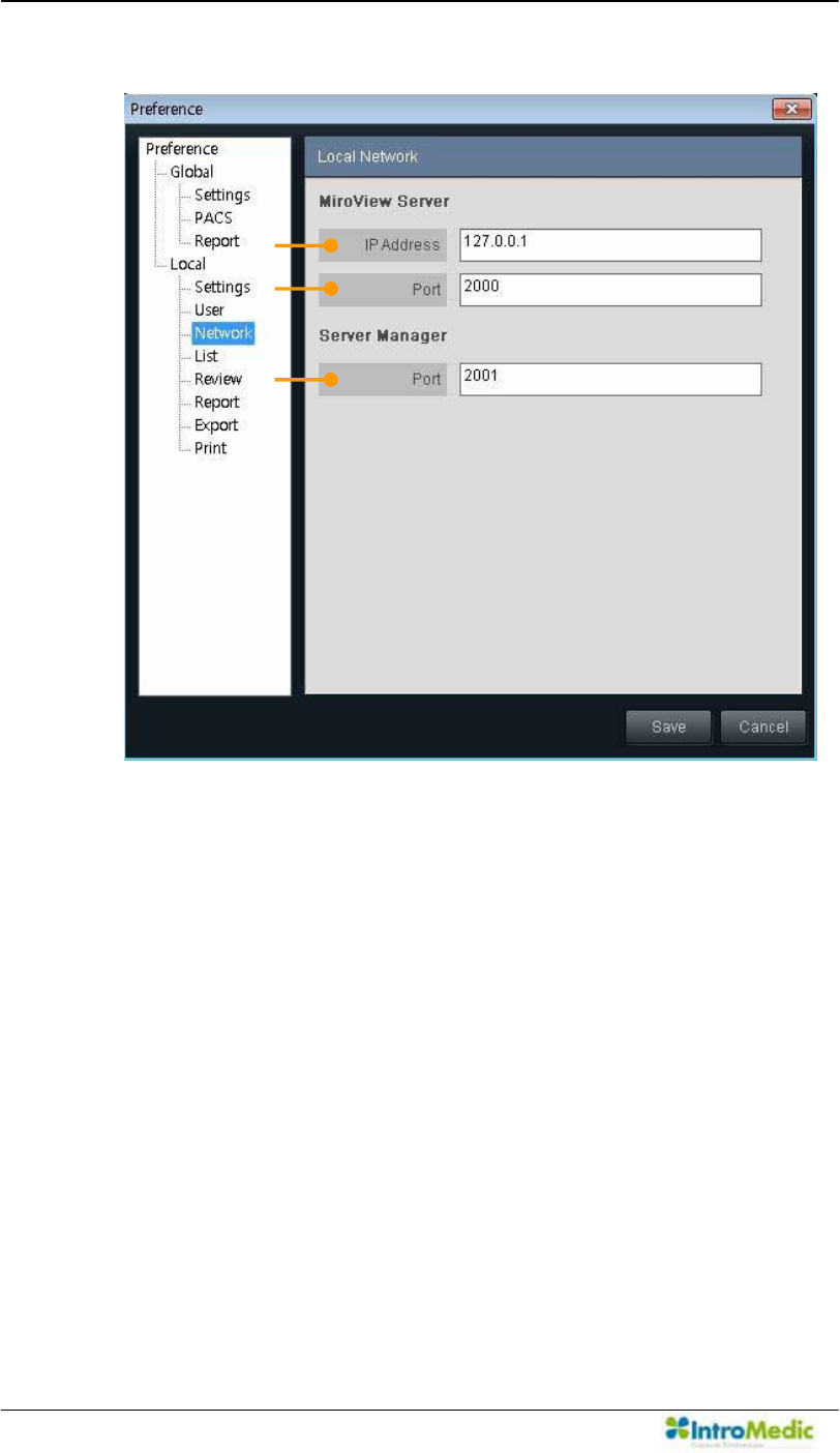
Using MiroView Software Chapter 4
4- 80
6) Local Network
i. 0LUR9LHZServer
ཛ IP Address: Input the IP Address where the 0LUR9LHZ
Server is installed.
ཛྷ Port: Input the port number to connect with the 0LUR9LHZ
Server.
ii. Server Manager: Utility to manage the 0LUR9LHZ Server
remotely.
ཝ Port: Input the port number for connection between Server
Manager and the 0LUR9LHZServer.
¤
¢
£
¢
£
¤
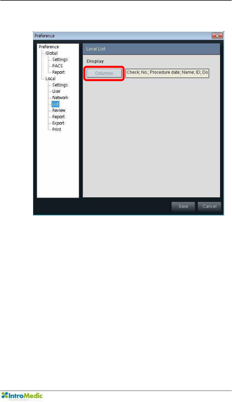
Chapter 4 Using 0LUR9LHZ Software
4-81
7) Local List
i. Display
Columns: Configure the columns which will appear on List.
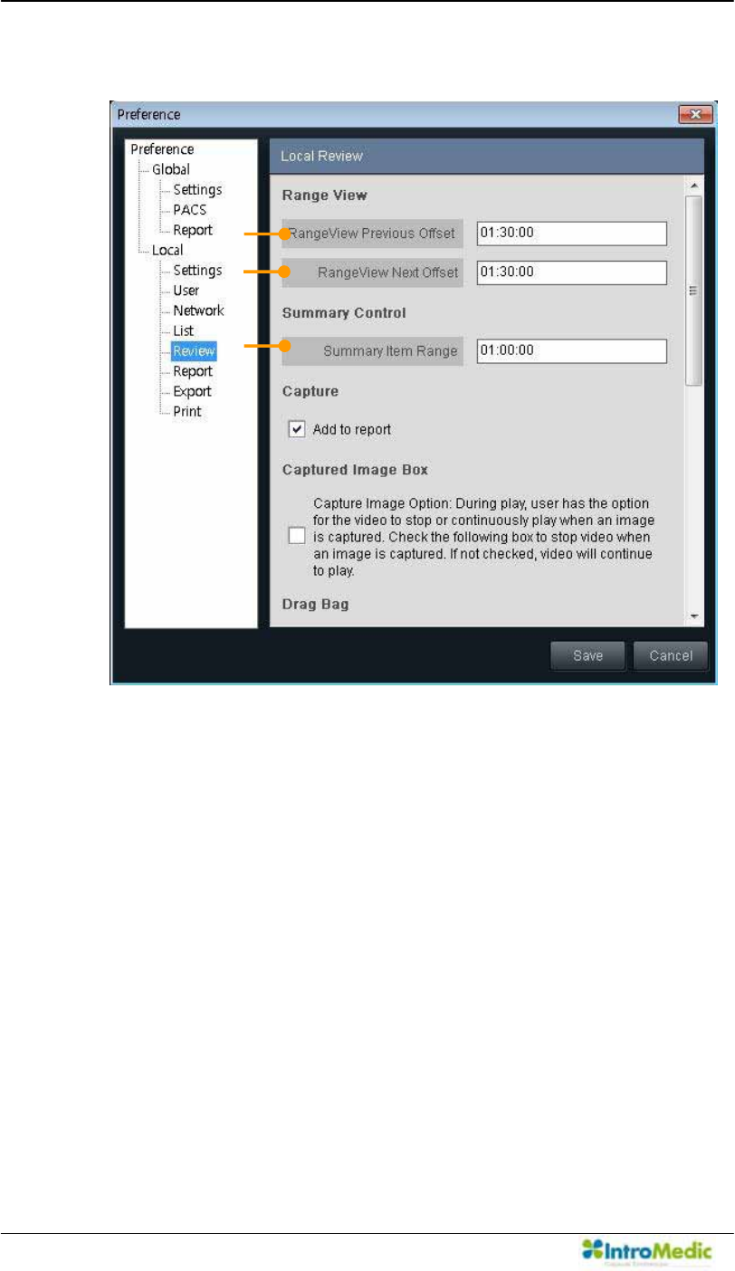
Using MiroView Software Chapter 4
4- 82
8) Review
i. Range View
ཛ Range View Previous Offset: Set the range for range view.
ཛྷ Range View Next Offset: Set the range for range view.
ii. Summary Control
ཝ Summary Item Range: Set the period of one item on the
Finding Summary Box.
iii. Capture
Add to report: If the checkbox is checked, the captured
images will be shown on Report Mode and added to the
final report. The added captured image can be removed
from the Report Mode.
¢
£
¤
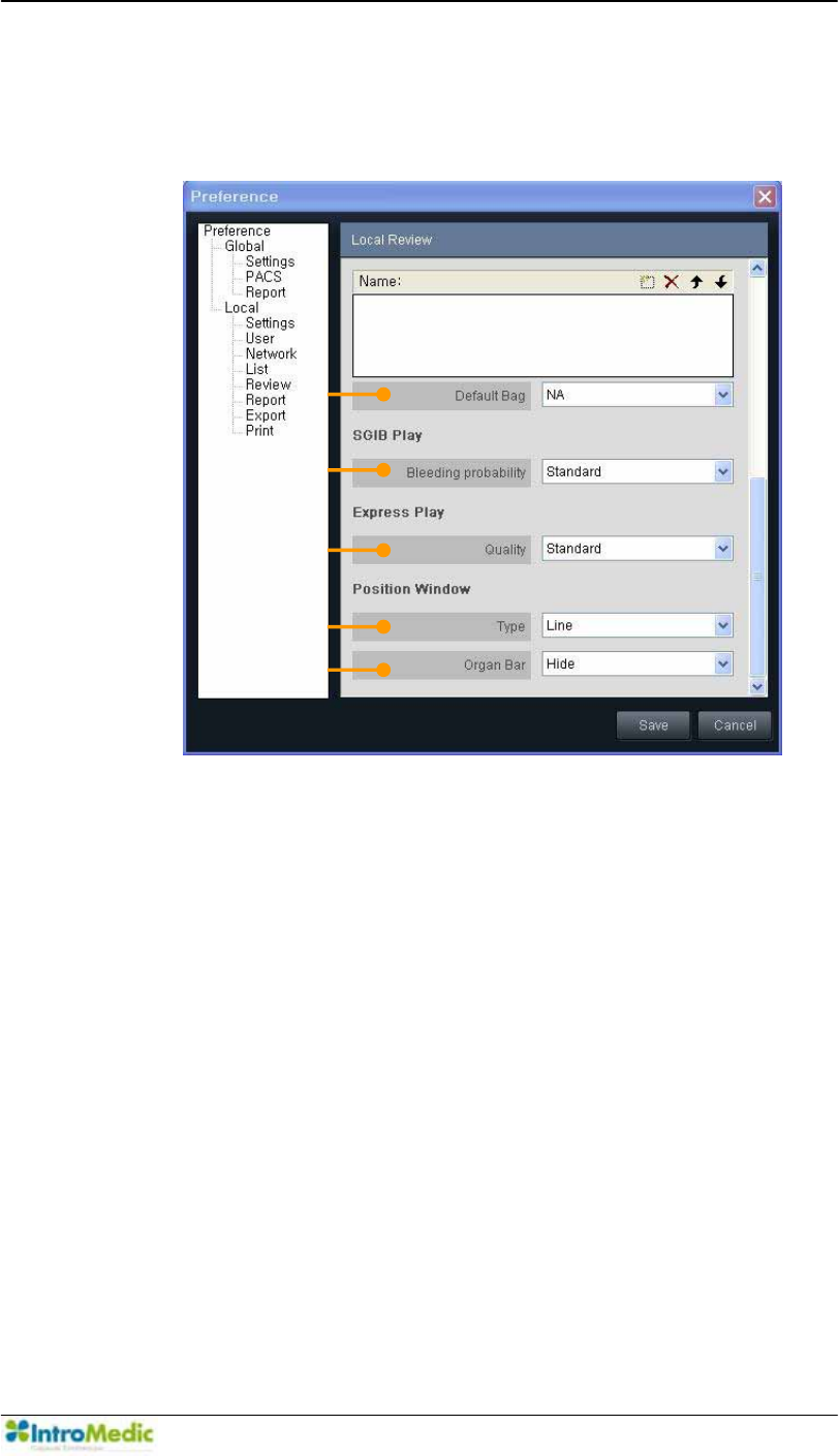
Chapter 4 Using 0LUR9LHZ Software
4-83
iv. Captured Image Box
Captured Image Option: If the checkbox is checked, the
video will stop when capturing an image on Review Mode.
v. Drag Bag: Drag Bag related setting. Add/Remove the Drag
Bags and set a Bag to Default Bag by choosing one from
the combo list. The Bags will be applied for the reviews
added newly. If the user makes a new review for a case or
open a case not reviewed and choose finding box for the
captured image box, the drag bags which are modified on
this preference will be shown.
¥
¦
§
¨
©

Using MiroView Software Chapter 4
4- 84
ཞ Default Bag: Set a Bag to Default Bag by choosing one
from the combo list on Drag Bag mode.
vi. SGIB Play
ཟ Bleeding probability: Choose the Bleeding probability to
play on SGIB Play. Set this value as Low to show many
images on SGIB Play or set high to show little images.
vii. Express Play
འ Quality: Choose the Quality to play on Express Play. Set
this value as Low to skip more images on Express Play
than High.
viii. Position Window
ཡ Type: Choose the type for the Position Window. If Line is
chosen, the trace of the MiroCam® Capsule will be
displayed in line. If Region is chosen, the position of the
MiroCam® Capsule will be displayed on region segmented.
ར Organ Bar: Choose the Organ Bar status. If Show is
chosen, the Organ Bar will appear on the Position Window.
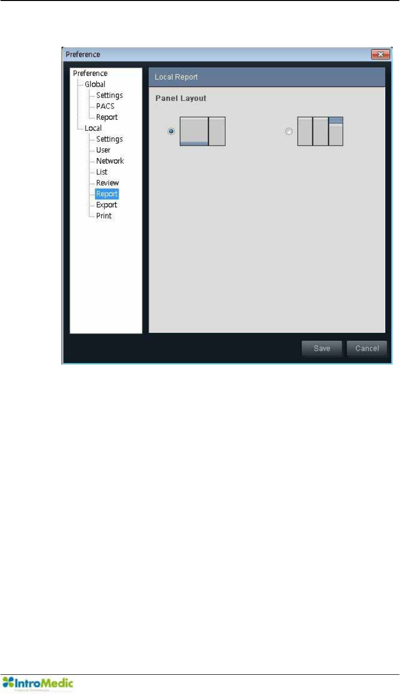
Chapter 4 Using 0LUR9LHZ Software
4-85
9) Local Report
i. Panel Layout: Choose the Panel Layout. The Panel Layout
will be shown as per the choice.
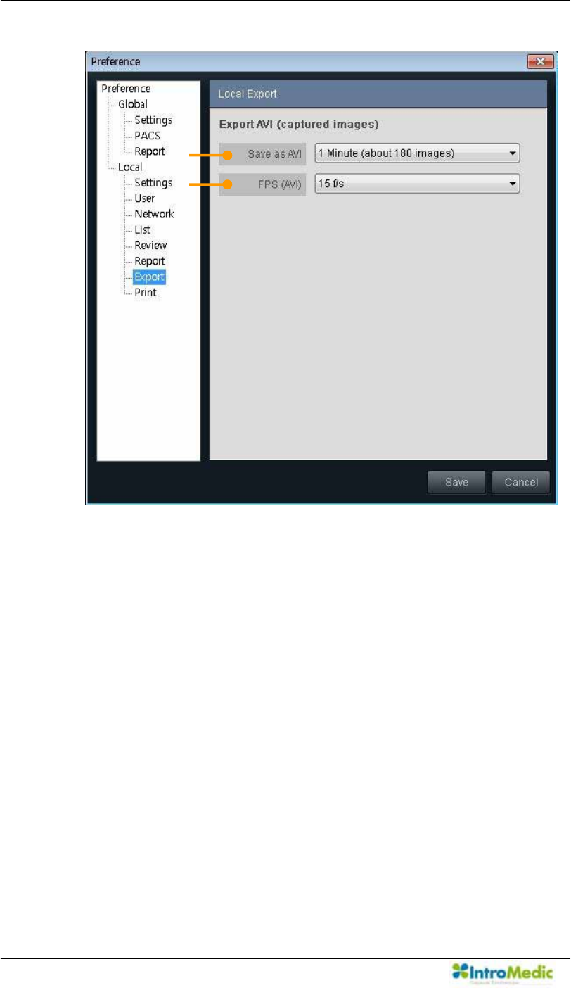
Using MiroView Software Chapter 4
4- 86
10) Export
i. Export AVI
ཛ Save as AVI: Set the length of the AVI to export.
ཛྷ FPS (AVI): Set the frame rate of the AVI to export.
¢
£
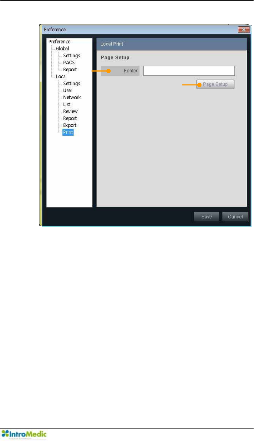
Chapter 4 Using 0LUR9LHZ Software
4-87
11) Local Print
ii. Page Setup
ཛ Footer: Type in the string for footer which will appear on
the final report.
¢
£
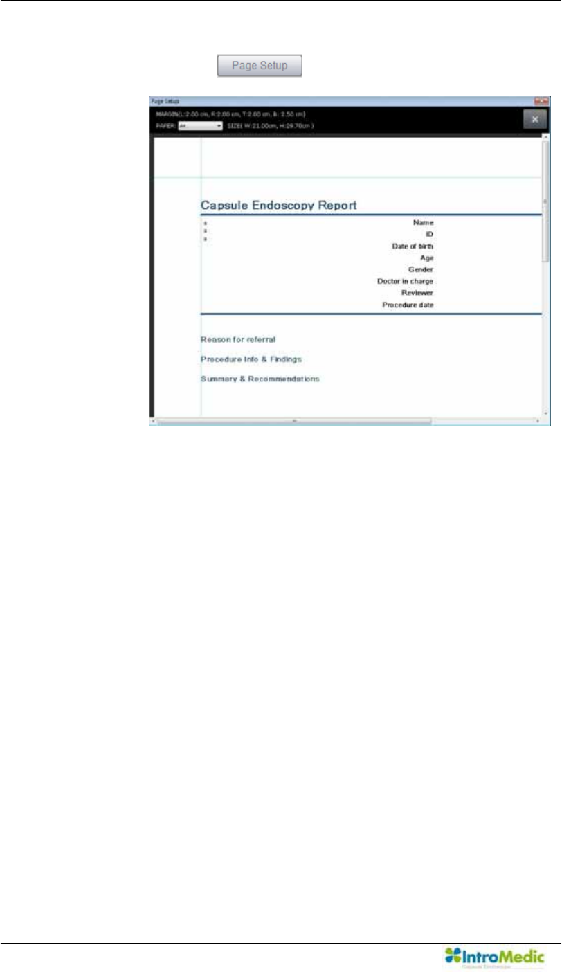
Using MiroView Software Chapter 4
4- 88
¤ Page Setup: Edit the layout of the report.
- Click the to show the Page Setup window.
- Choose the paper type; A4 or Letter and adjust the
margins for Header, Footer, Right and Left.
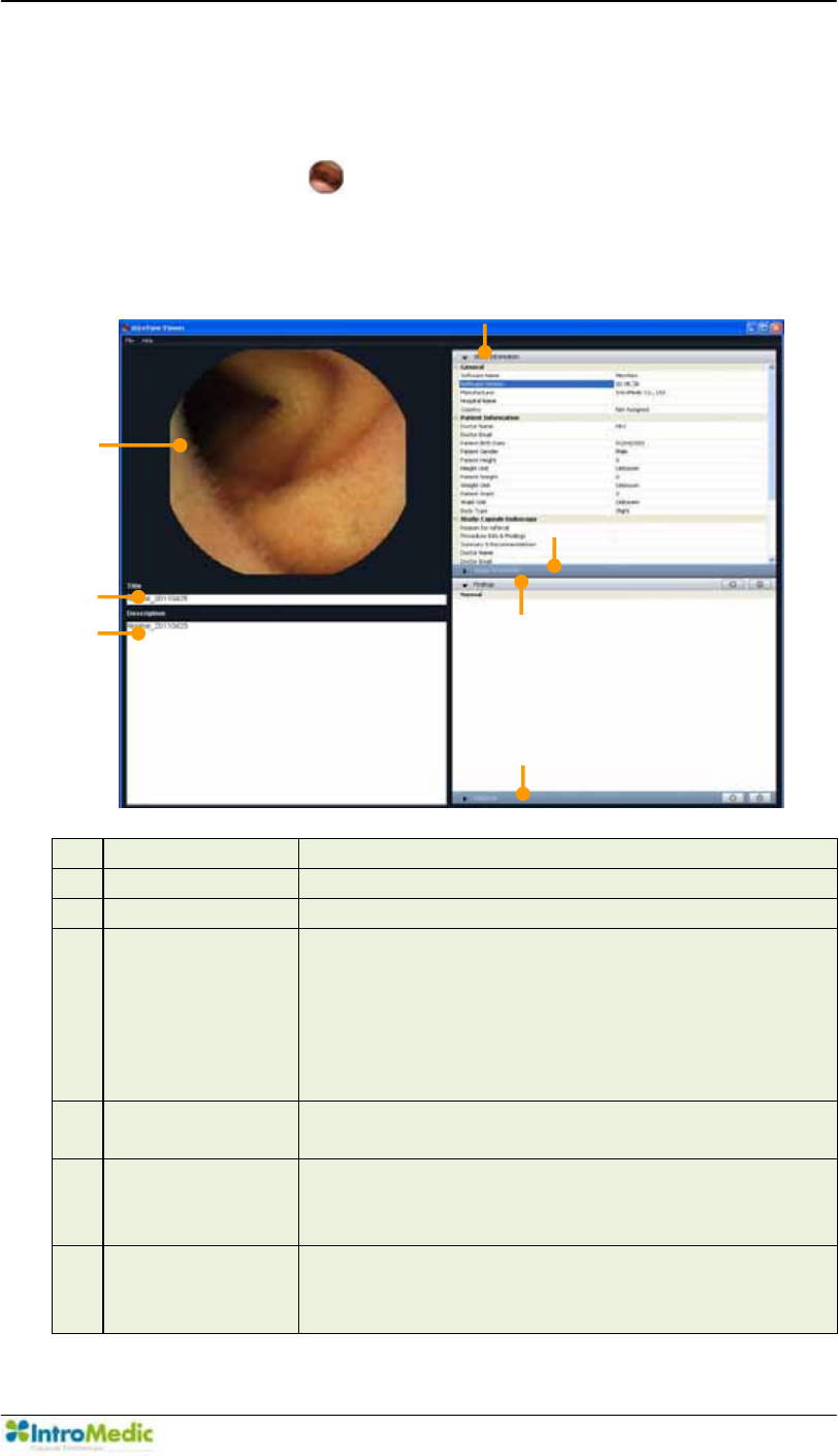
Chapter 4 Using 0LUR9LHZ Software
4-89
4.5 Overview - 0LUR9LHZViewer
4.5.1 Start 0LUR9LHZViewer
Double-click the to run the 0LUR9LHZ Viewer. Open an
Image File (EXMIF-Exchangeable Medical Image Format data or
-3(*YLDµ)LOH-!2SHQ¶IXQFWLRQ
£ Image Display Image Display Area (EXMIF or JPEG)
¤ Title Title for the image in the Image Display
¥ Description Description for the image in the Image Display
¦ Study
Information
General Information (Software / Manufacturer /
Hospital Information), Patient Information
(Doctor, Patient Body Shape) and Study
Information (Doctor, Receiver, Capsule and
Procedure Information) for the image in the
Image Display
§ Image
Information
Creator Information and/or Finding Comments
for the image in the Image Display
¨ Findings Findings information the creator captured and
commented before for the image in the Image
Display.
© Diagnosis Diagnosis information the creator captured and
commented on for the image in the Image
Display.
d
e
f
g
h
c
i
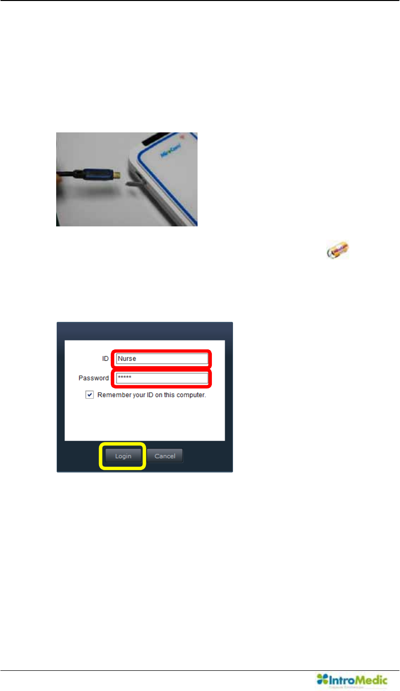
Using MiroView Software Chapter 4
4- 90
4.6 Performing Capsule Endoscopy
4.6.1 Initializing Receiver
Connect the MiroCam® Receiver to the workstation via USB port.
Run the 0LUR9LHZOperator by double-clicking the on the
desktop or from the Windows Start-up menu. Log in.
Carry out in alphabetical order like following picture.
Ü
Ú
Û
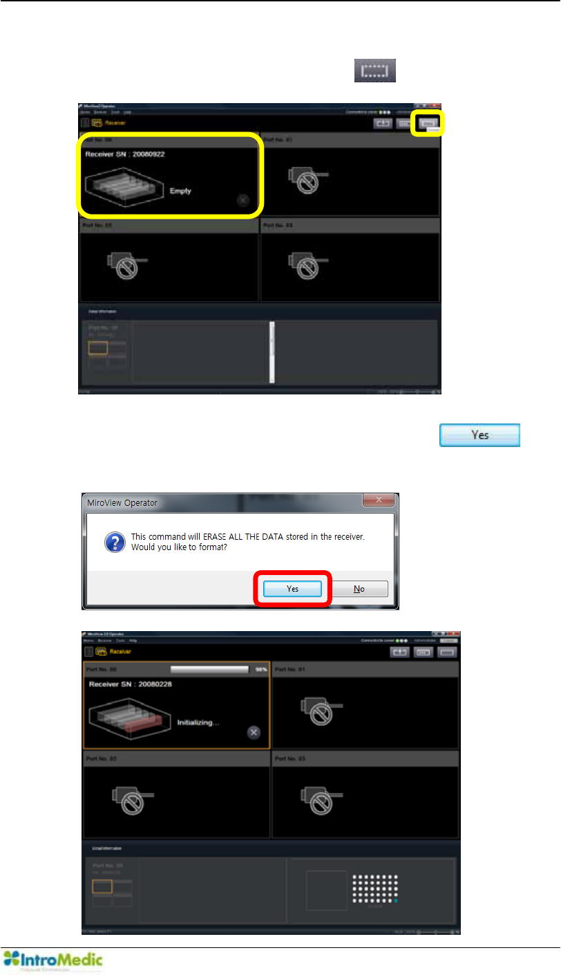
Chapter 4 Using 0LUR9LHZ Software
4-91
Enter the MiroCam® Receiver mode and select the MiroCam®
Receiver port to initialize and click the .
When following message will appear, click the to
start the initializing process.
Ú
Û
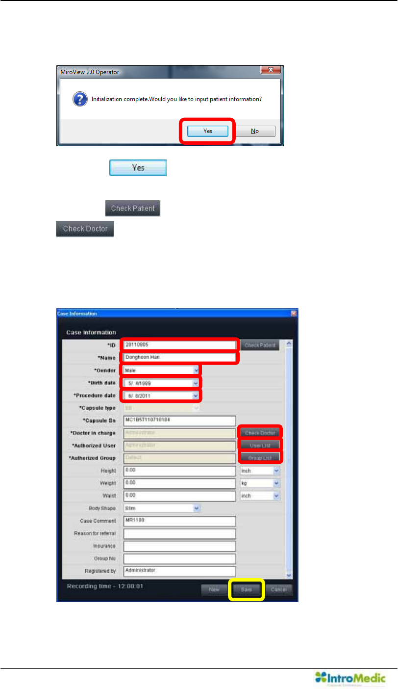
Using MiroView Software Chapter 4
4- 92
After the initializing process is complete, the following message
will appear.
Click the and the Patient Information window will
appear. Input the patient information for each field.
Click the to input the patient name and then click the
to input the doctor name.
7\SHLQWKHSDWLHQW¶VQDPHDQGWKH,'LQWRWKHDSSURSULDWHILHOGV
directly.)
Carry out in alphabetical order like following picture.
(The fields marked with * is required.)
ß
à
á
Ú
Û
Ü
Ý
Þ
â
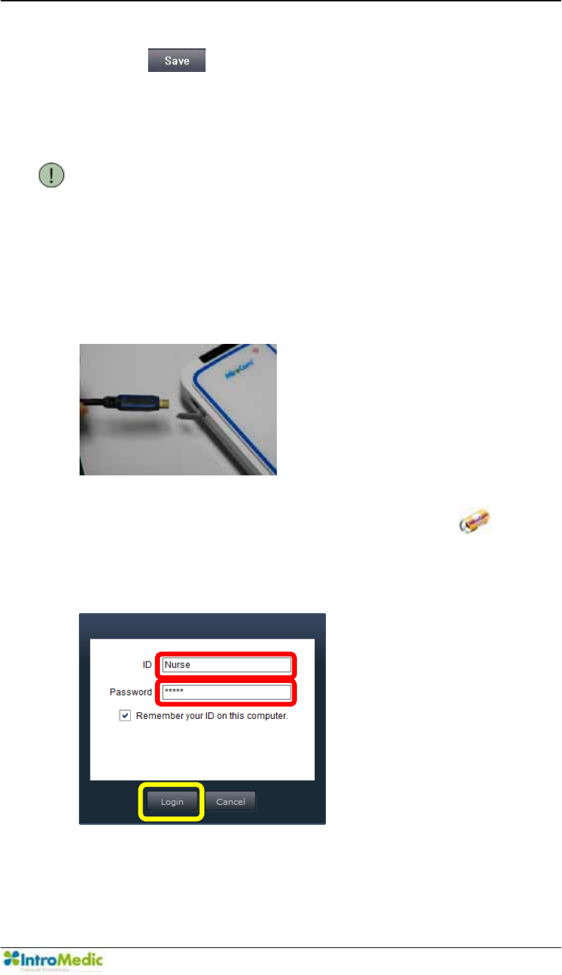
Chapter 4 Using 0LUR9LHZ Software
4-93
Click the to save the Case Information to the MiroCam®
Receiver. The MiroCam® Receiver is now ready for the
MiroCam® Capsule endoscopy procedure.
NOTE The fields in the Case Information are editable,
and additional fields can be added. This can be
accessed via Tools Æ Preferences Æ Receiver
Æ Set Æ Add / Modify.
4.6.2 Upload Image Data (0LUR9LHZOperator)
Connect the MiroCam® Receiver to the workstation via USB port.
Run the 0LUR9LHZOperator by double-clicking the on the
desktop or from the Windows Start-up menu. Log in.
Carry out in alphabetical order like following picture.
Ü
Ú
Û
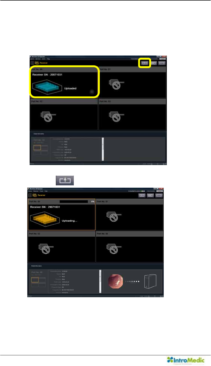
Using MiroView Software Chapter 4
4- 94
After switching the MiroCam® Receiver on, enter the MiroCam®
Receiver mode and select the proper the MiroCam® Receiver
port to upload the image data.
Carry out in alphabetical order like following picture.
Click the to start the Upload.
Ú
Û
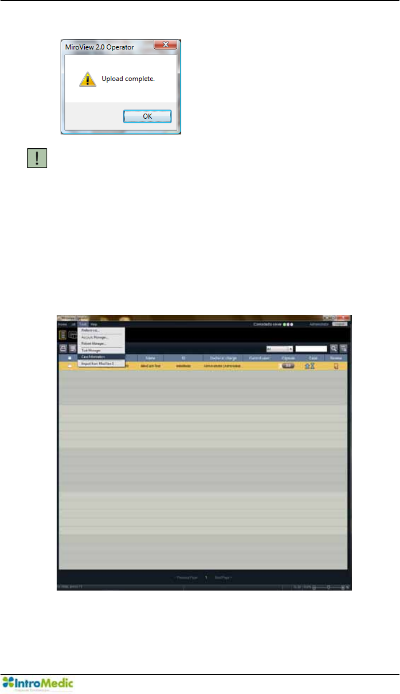
Chapter 4 Using 0LUR9LHZ Software
4-95
After completing the Upload, the following message will appear.
CAUTION When the MiroView˞ Operator is running on a
64bits OS, Do not turn off or disconnect any
MiroCam® Receivers connected to the workstation
while uploading.
4.6.3 Change Patient Information After uploading the Image Data
(Optional)
From the 0LUR9LHZ 2SHUDWRU XQGHU µ7RROV¶ -! 6HOHFW µ&DVH
,QIRUPDWLRQ¶
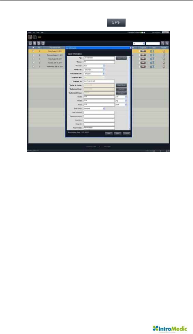
Using MiroView Software Chapter 4
4- 96
7KHQ µ&DVH ,QIRUPDWLRQ¶ GLDORJ ER[ ZLOO SRSV XS &KDQJH WKH
patient information and click the .
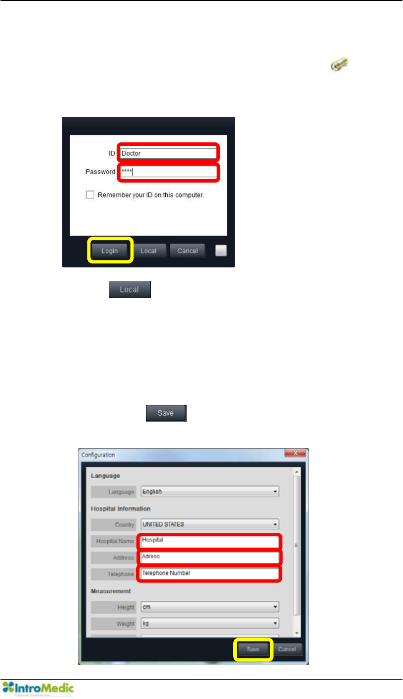
Chapter 4 Using 0LUR9LHZ Software
4-97
4.6.4 Review (0LUR9LHZClient)
Run the 0LUR9LHZ Client by double-clicking the on the
desktop or from the Windows Start-up menu. Log in.
Carry out in alphabetical order like following picture.
Click the on the Log-in screen to run the 0LUR9LHZ
client as Local Mode. (See 8VLQJ 0LUR9LHZ &OLHQW DW
Local PC without FRQQHFWLQJ WR 0LUR9LHZ 6HUYHU for
details.)
- $W WKH ILUVW UXQQLQJ RI µ/RFDO 0RGH¶ WKH ZLQGRZ ZLOO DSSHDU
like below. Input the appropriate values in to the empty fields
and click the to proceed.
- Carry out in alphabetical order like following picture.
Ü
Ú
Û
Ú
Û
Ü
Ý
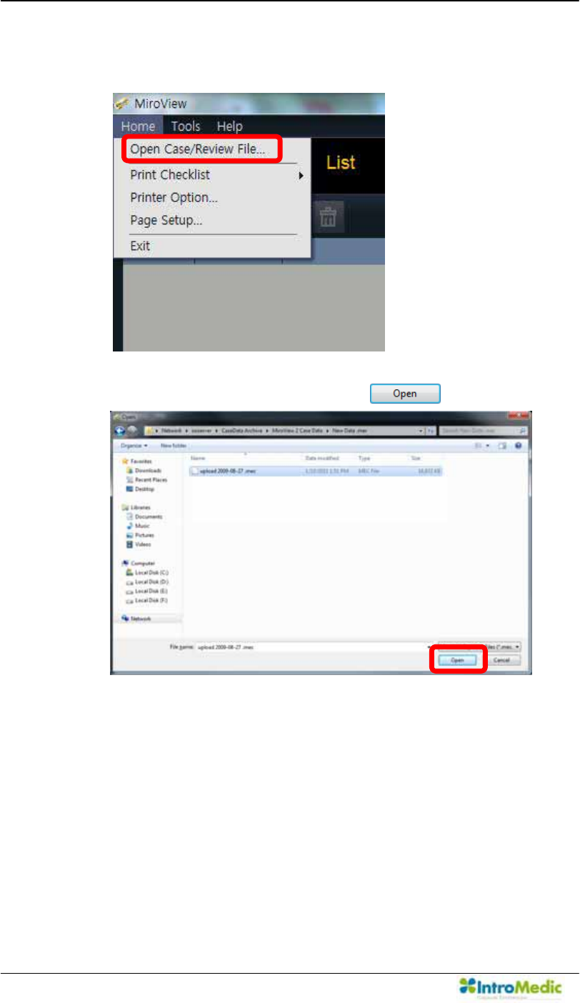
Using MiroView Software Chapter 4
4- 98
- Open the Case/Review via Menu Æ Home Æ Open
&DVH5HYLHZILOH«.
- Choose a file to open and click the .
- After completely reviewing the file, save the review via
Menu
Æ
Home
Æ
Save Active Review so that the user can
import the edited review file on the MLUR9LHZ6HUYHULQWKH
future.
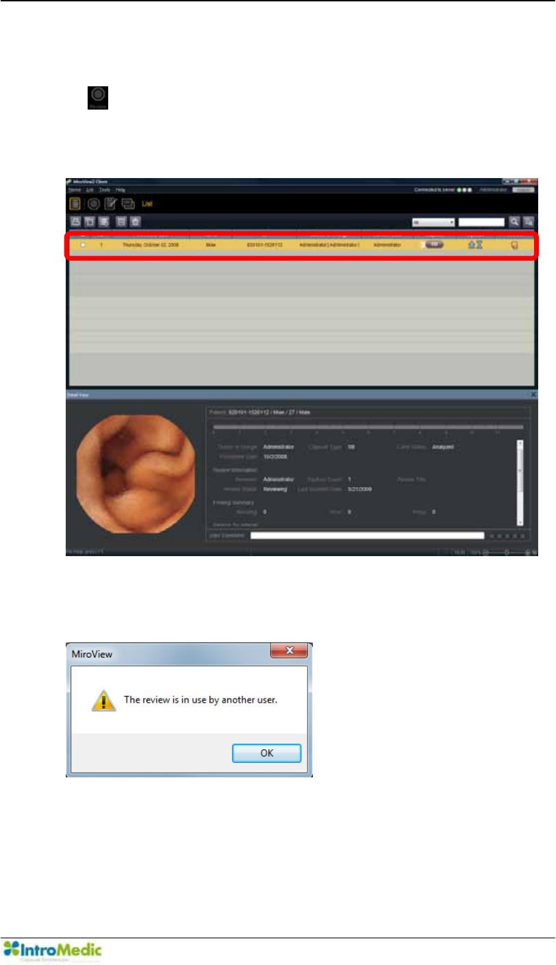
Chapter 4 Using 0LUR9LHZ Software
4-99
Select the Patient Video Data on the List Mode
- Select a patient video data to review from the List Mode and click
the to enter the Review Mode.
- Check to see if another user is reviewing the patient file on the
Current User column in the List Mode.
- If the patient file is being reviewed by another user, a message will
appear.
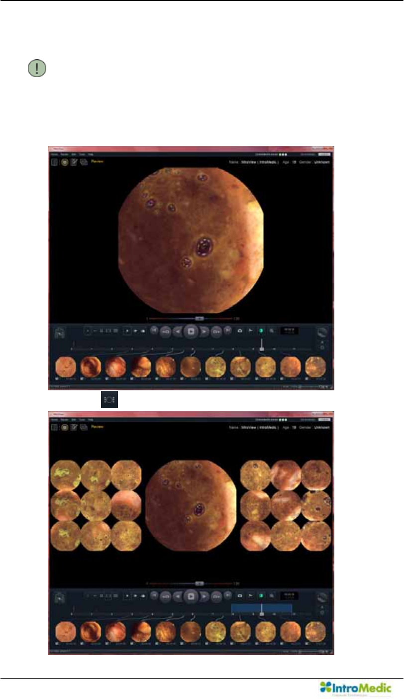
Using MiroView Software Chapter 4
4- 100
Review the Patient Video on the Review Mode
NOTE When using network connection between the
0LUR9LHZ Server and the 0LUR9LHZ Client, for
efficient video playback the video is cached locally
in the server. During this buffering process, the
video may be reviewed.
± Click the to readily set landmarks
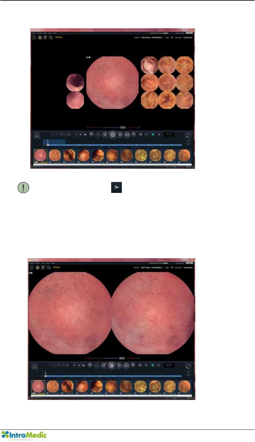
Chapter 4 Using 0LUR9LHZ Software
4-101
- Use the Range View and Map View to find all the landmarks.
NOTE Click the and select landmark type:
Esophagus, Gastric, Duodenum, Ileo-cecal, Cecal
and User landmark.
- After marking the necessary landmarks, play the video via the
Express Play and capture abnormalities and / or suspected disease
pathologies in the small bowel.
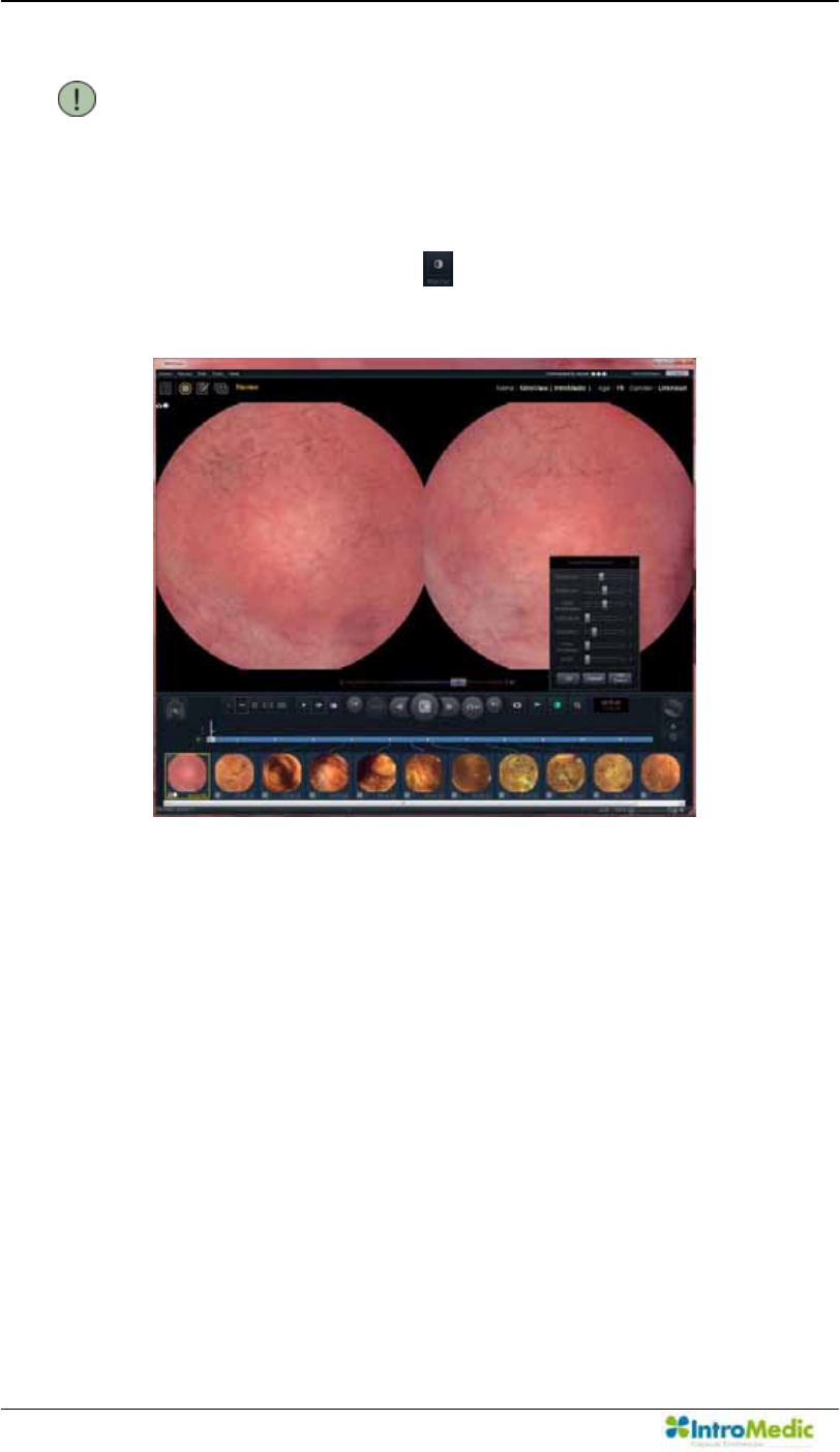
Using MiroView Software Chapter 4
4- 102
NOTE 7KH XVHU FDQ SUHVV µ(QWHU¶ NH\ WR FDSWXUH WKH
image.
- To identify abnormalities and/or disease pathology more easily,
use the Image Enhancement function to adjust preferred
image settings. Click the to open the Image Enhancement
window.
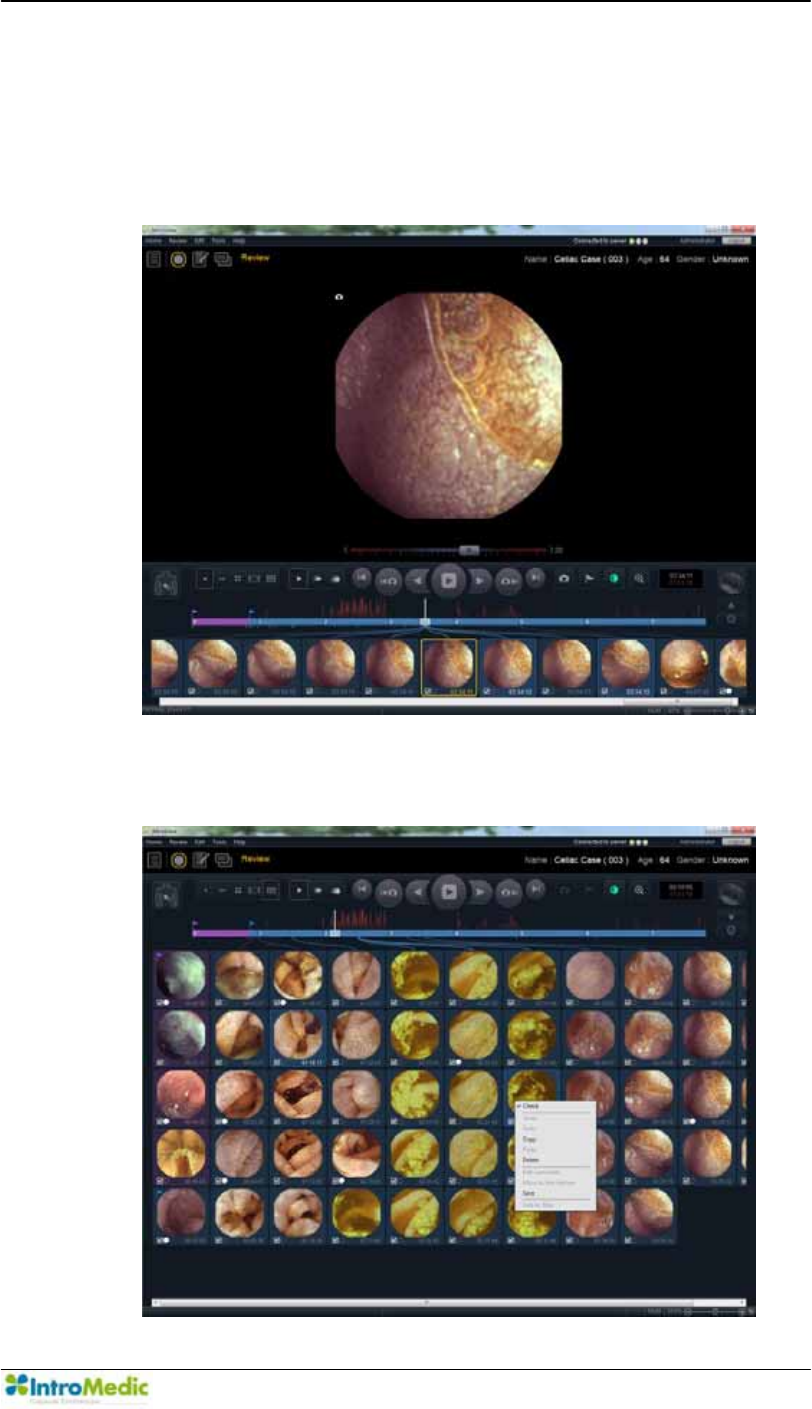
Chapter 4 Using 0LUR9LHZ Software
4-103
Converting AVI File
- Click two images (the first image and the last image) while
holding the < Ctrl > key among the to convert the segment to
an AVI file.
- Right mouse click and select µSave¶ from dialog box.
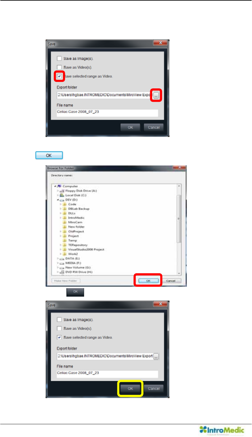
Using MiroView Software Chapter 4
4- 104
- 2QO\FKHFNµ6DYHVHOHFWHGUDQJHDV9LGHR
- Carry out in alphabetical order like following picture.
Choose the location you want to save this file and click the
.
Click the to save selected range as Video.
Û
Ú
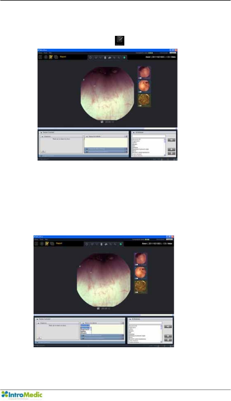
Chapter 4 Using 0LUR9LHZ Software
4-105
Composing the Report on the Report Mode
- After capturing images of suspected disease in the Review
Mode pathology, click the to enter the Report Mode.
- Use the auto complete dictionary slide and choose available
disease pathology from the list.
- 7KH XVHU FDQXVH KRW NH\ µ&WUO 6SDFH¶ RU µ&WUO (QWHU¶ WR XVH
auto complete function while composing comments. Select a
word from the list after pressing the hot key.
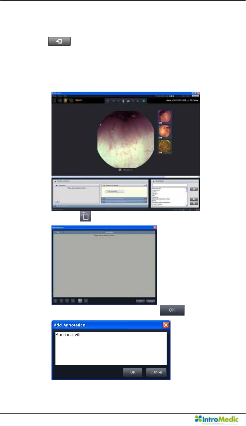
Using MiroView Software Chapter 4
4- 106
- The user can add the word shown on the GI Dictionary into the
text comment by double-clicking the appropriate word or clicking
the .
- The user can prepare Annotations for use by right clicking the
mouse in the comments area.
x Click µEdit Annotation¶.
x Click the .
x Input annotation and then click the .
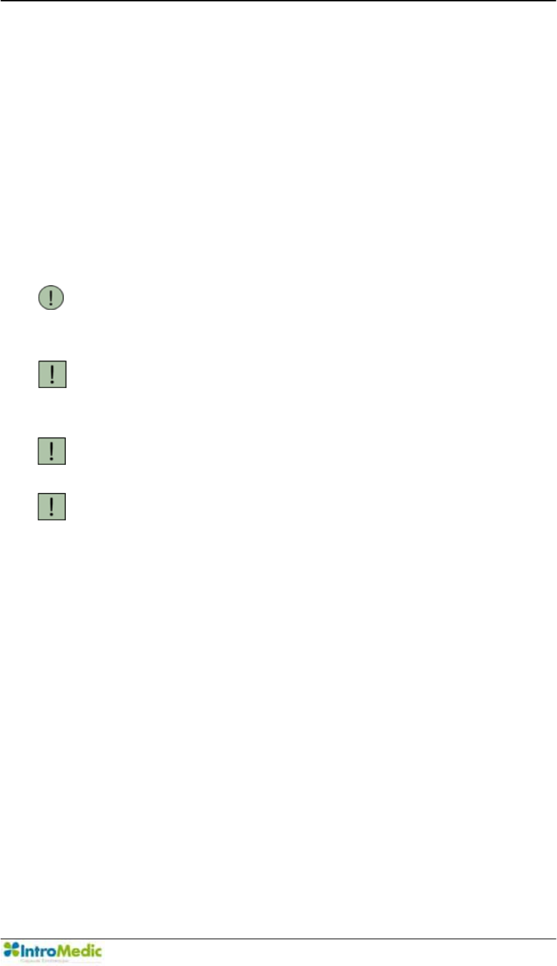
Chapter 4 Using 0LUR9LHZ Software
4-107
- Completing the report:
x Complete image comments for captured images (as
required)
x Complete the following tabs: Reason for referral; Procedure
Info & Findings; and Summary & Recommendations
x After completing the report, enter the Export Mode to print
out the complete report and/or export the 0LUR9LHZ
Software data.
NOTE The GI Dictionary tab and findings tab allow the
user to adjust the findings and the level of severity.
The user can use the GUI easily.
CAUTION DO NOT detach and/or attach the Microphone
from/to the workstation while recording the audio
comment.
CAUTION Sound Card Driver must be installed prior to using
the Recording function.
CAUTION Prior to recording the comments, close all the
applications using the Sound Card such as
music/video player.
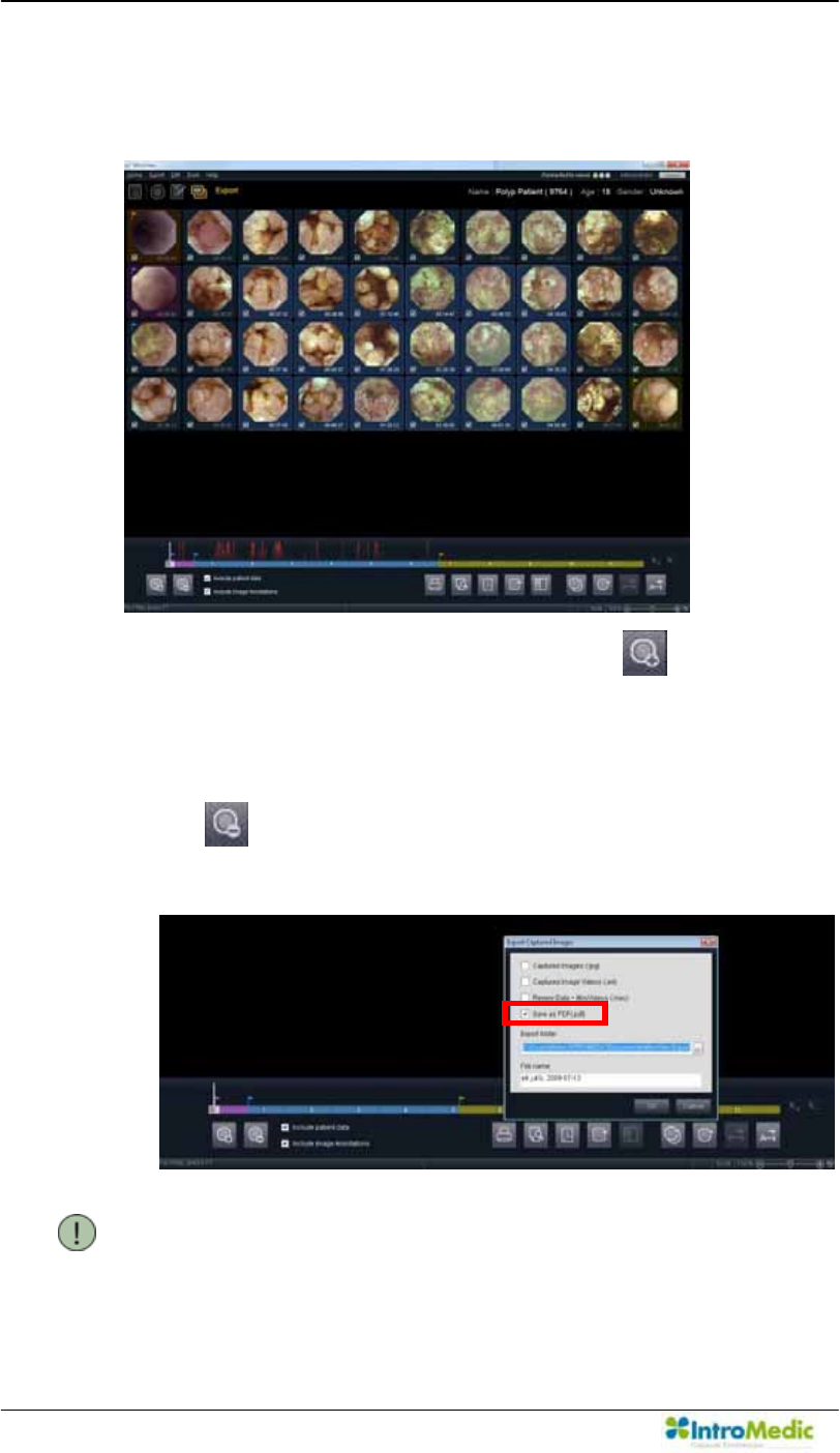
Using MiroView Software Chapter 4
4- 108
Print report, create file and export the Review on the Export
Mode.
- Select the images to select and click the and add the
selected captured images to the candidate list to export.
(Remove the selected images from the candidate list using
the )
- The µ6DYHDV3')¶IXQFWLRQLVXSGDWHG
NOTE User is able to change default settings on whether
or not to add the images on the report via Tools ->
Preference -> Review.
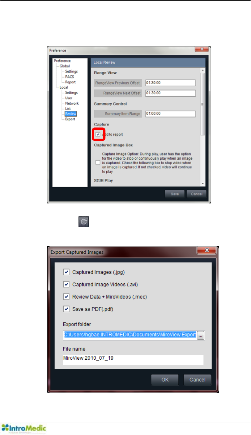
Chapter 4 Using 0LUR9LHZ Software
4-109
- Check to include on the report when capturing the image.
- Uncheck to not include the images on the report.
- Click the to use export function. A window will appear like
below.
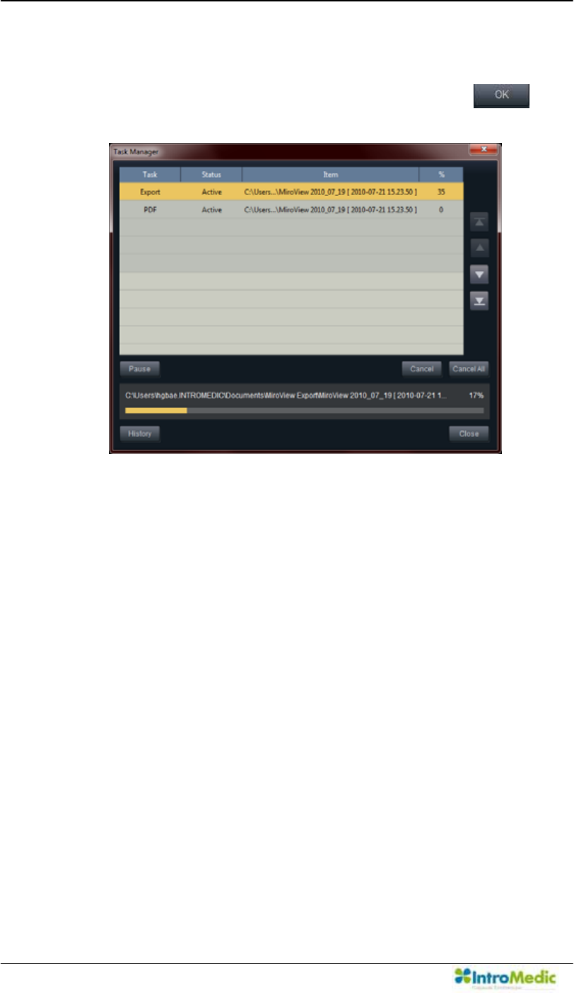
Using MiroView Software Chapter 4
4- 110
- Select the File Type to export and change the desired file
location on the Selected Folder and click the . A
window will appear with a progress bar.
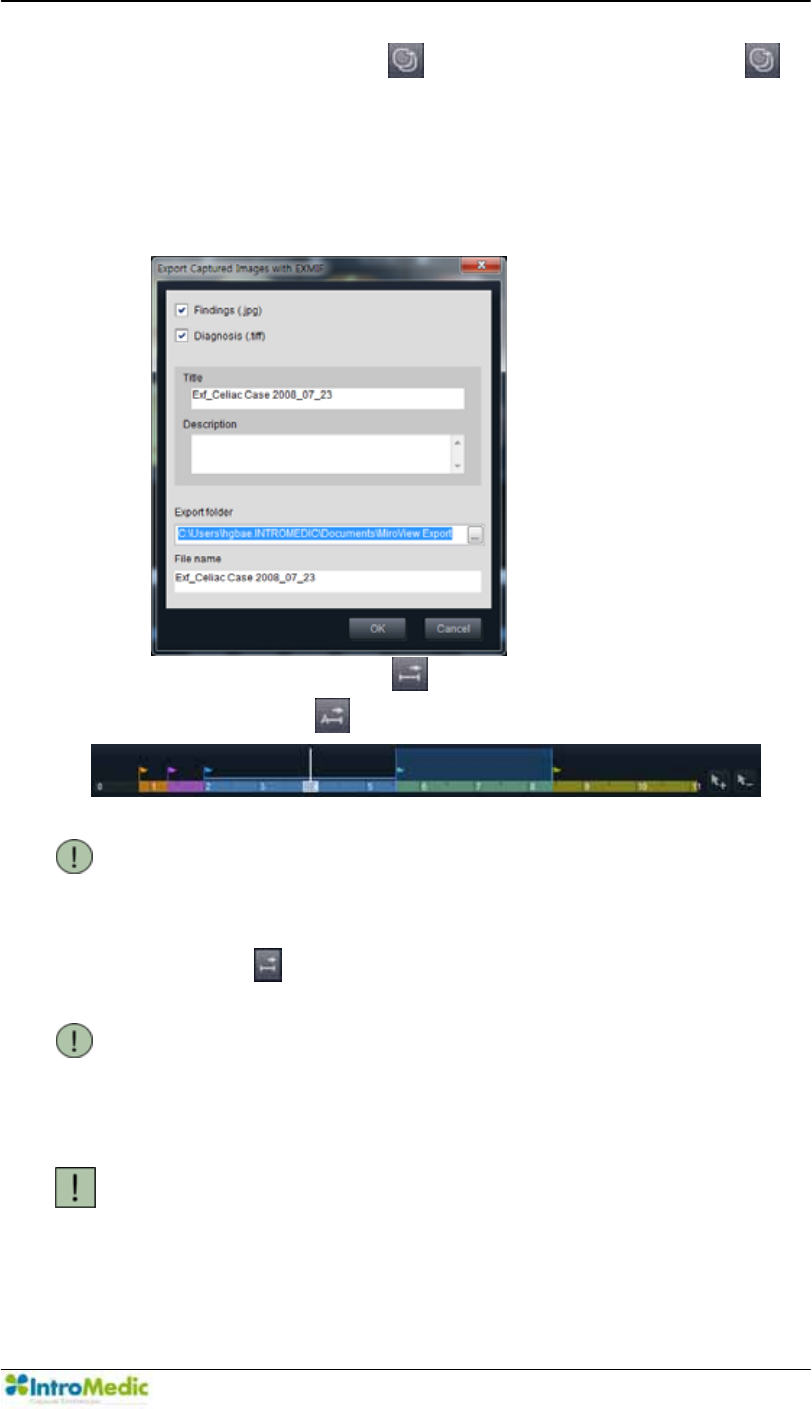
Chapter 4 Using 0LUR9LHZ Software
4-111
- The user can use the for EXMIF. When clicking the ,
the window will appear like below. The user can configure the
EXMIF properties: title and description. Findings will be saved
as the JPEG file format(.jpg) and diagnosis images will be
saved as the multiple image file format(.tiff)
- The user can use the for Segment Export (Video / Miro
Video) and the for Export Case function.
NOTE Select the segments on the Timebar to export by
selecting two captured images to set as the start
point and the end point respectively, or by clicking
the landmark flag. If no segment is selected, the
to export segments would be disabled.
NOTE MiroVideo includes selected Segments so that the
XVHUFDQFRQILUPWKHFRQWHQWVDQGHGLWIURPµ2SHQ
&DVH5HYLHZILOH«¶µ,PSRUW&DVH5HYLHZILOH«¶
main menu.
CAUTION It is highly recommended to constantly back up
patient data through export function in order to
prevent the data loss.
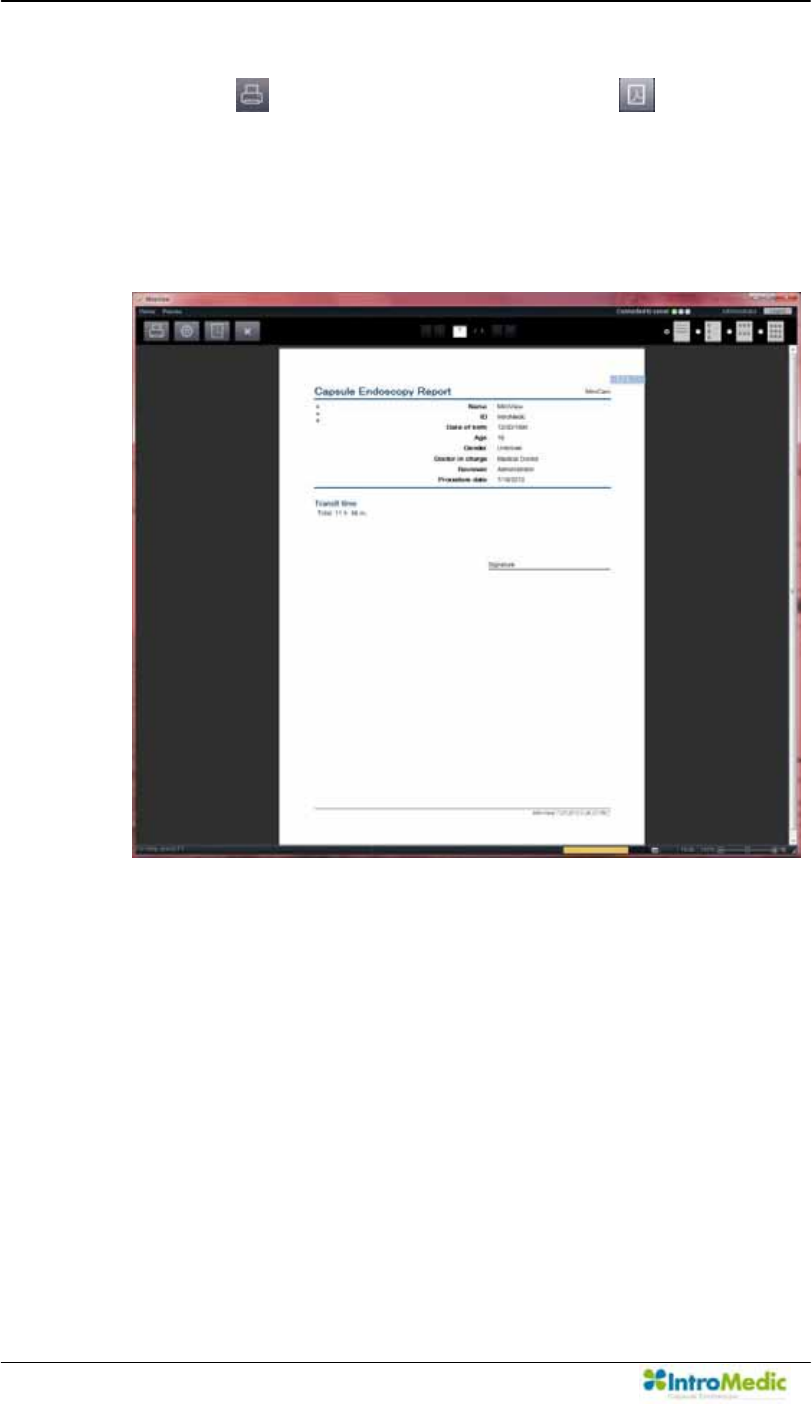
Using MiroView Software Chapter 4
4- 112
Print Report and save the report as PDF on the Report Preview
- Click the to print reports and/or click the to save the
report as PDF.
- Show report preview on the screen. The user can include or
exclude findings/diagnosis data on the final report via Menu
Æ
Preview
Æ
Including findings & diagnosis data.
- The user can print out the report and save the report to PDF file
in this screen.
- IIWKHXVHUVHOHFWVWKHLPDJHVSHUSDJHPRGHWKHPHVVDJHµ,I
you proceed with the current Layout mode, image comments
may be omitted and not printed. Please select 3 images per
SDJH PRGH WR LQFOXGH DOO FRPPHQWV LQ WKH UHSRUW¶ ZLOO DSSHDU
This will be defaulted during the next use in that the workstation
for all users.
- If the user selects the Draft report, no captured images will be
included in the final report.
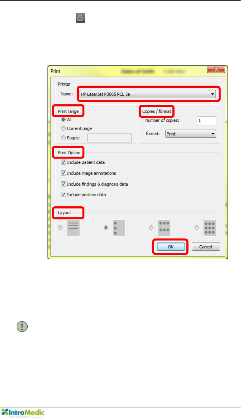
Chapter 4 Using 0LUR9LHZ Software
4-113
- Click the to print the report, the Print window will appear.
- Choose the desirable Printer, Print Ranage, Copies/format,
Print Option and Layout.
- Carry out in alphabetical order like following picture.
- The 0LUR9LHZSoftware privides the ODF for the soft copy
of the report so that the user can open the ODF report in
other word processors; MS Word and Haansoft; ODF is
available for 3 images layout only.
NOTE The previous software version (0LUR9LHZ
Software 1.0) did not support the draft report style.
Ü
ß
Þ
Ý
Û
Ú
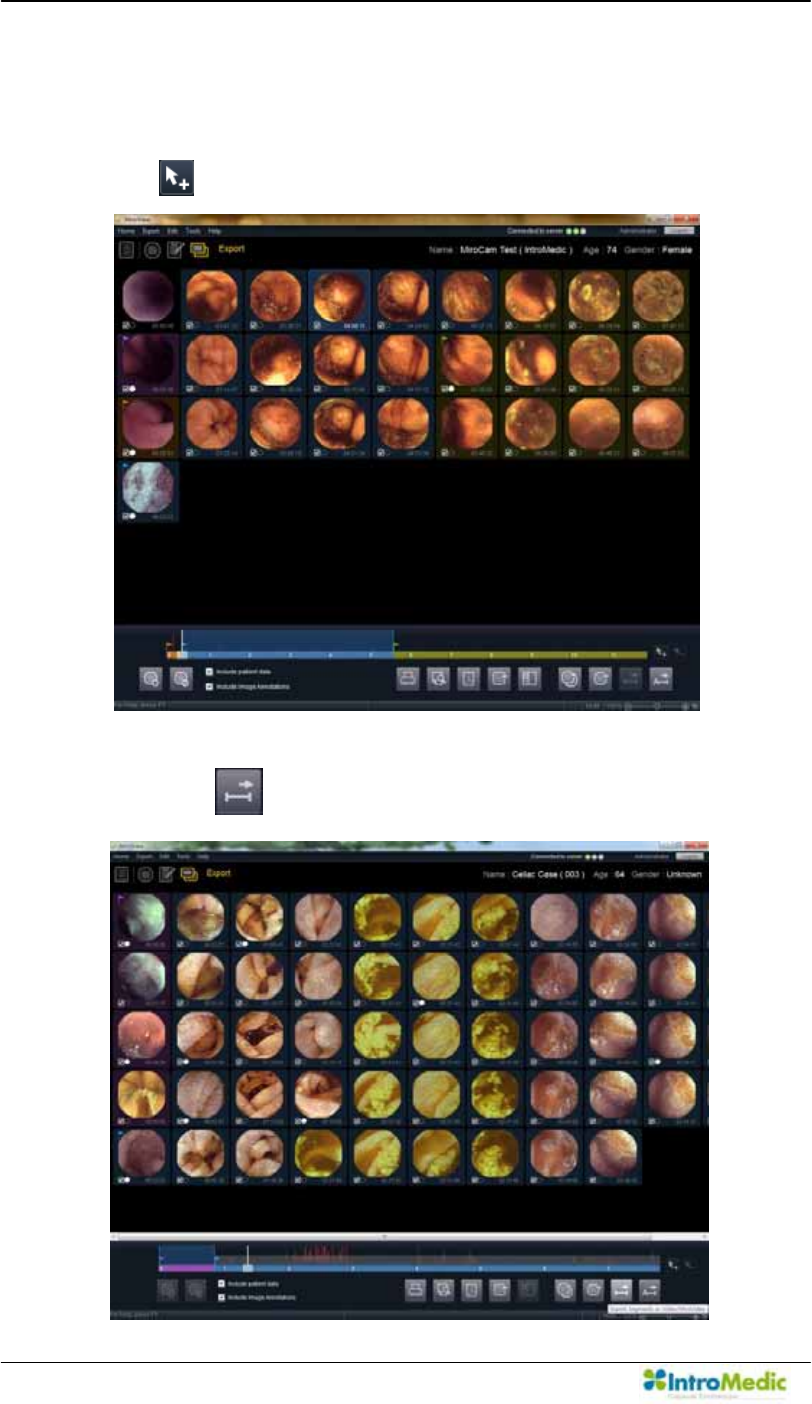
Using MiroView Software Chapter 4
4- 114
Back up the segment
- If a hospital wants only back up small bowel section, they can
XVHWKLVIHDWXUH )URPµ([SRUW¶PRGH VHOHFWWKHUDQJH DQG FOLFN
the to add segment first.
- Click the ., Export Segments as Video/MiroVideo.
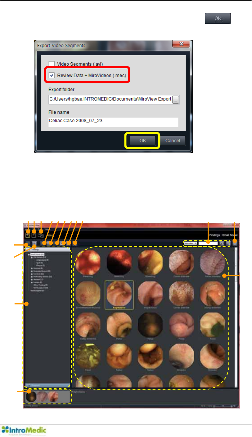
Chapter 4 Using 0LUR9LHZ Software
4-115
- 6HOHFWµ5HYLHZ'DWD0LUR9LGHRVPHFDQGFOLFNthe .
- Carry out in alphabetical order like following picture.
4.6.5 Image Atlas
Atlas
The following picture show via Help
Æ
Atlas
c
d
e
h
i
j
k
f
g
̺
13
l
̺
11
̺
12
̺
14
̺
15
̺
16
Û
Ú

Using MiroView Software Chapter 4
4- 116
£ Atlas Default Atlas Images
¤ My Atlas Atlas Images configured by the user
¥ Atlas + My Atlas Show Atlas Images and My Atlas Images at
once.
¦ Import Atlas
Images from file
Import Atlas Images from file; BMP, JPEG,
GIF, EMF, WMF, TIFF and PNG file format.
§ Export Atlas
Images to file(s)
Export Atlas Images to file; BMP, JPEG, GIF,
EMF, WMF, TIFF and PNG file format.
¨ Edit Information Edit the Information of the selected Atlas
Image.
© Export Atlas
Image(s) to E-
mail
Export selected Atlas Image(s) and send it /
them to another doctor via E-mail.
ª Delete Atlas
Image(s)
Delete the selected Atlas Image(s)
« Print Atlas
Image(s)
Print the selected Atlas image(s)
¬ Save as PDF Save the selected Atlas Image(s) as PDF
Show/Hide
Marks
Show / Hide Marks on the Atlas Image(s)
® Search Search the Atlas Image
¯ Comparison
Window
Show the Comparison Window
° Browser
Tab(Findings /
Diagnosis)
Area to select the Category of the Atlas Image
and to see the selected image.
± Recent Images Images the user saw on the Comparison
Window
ԧ Atlas Thumbnail
Area
Area to select the Atlas Image. Double-click
the Atlas Image to see the Image Information.
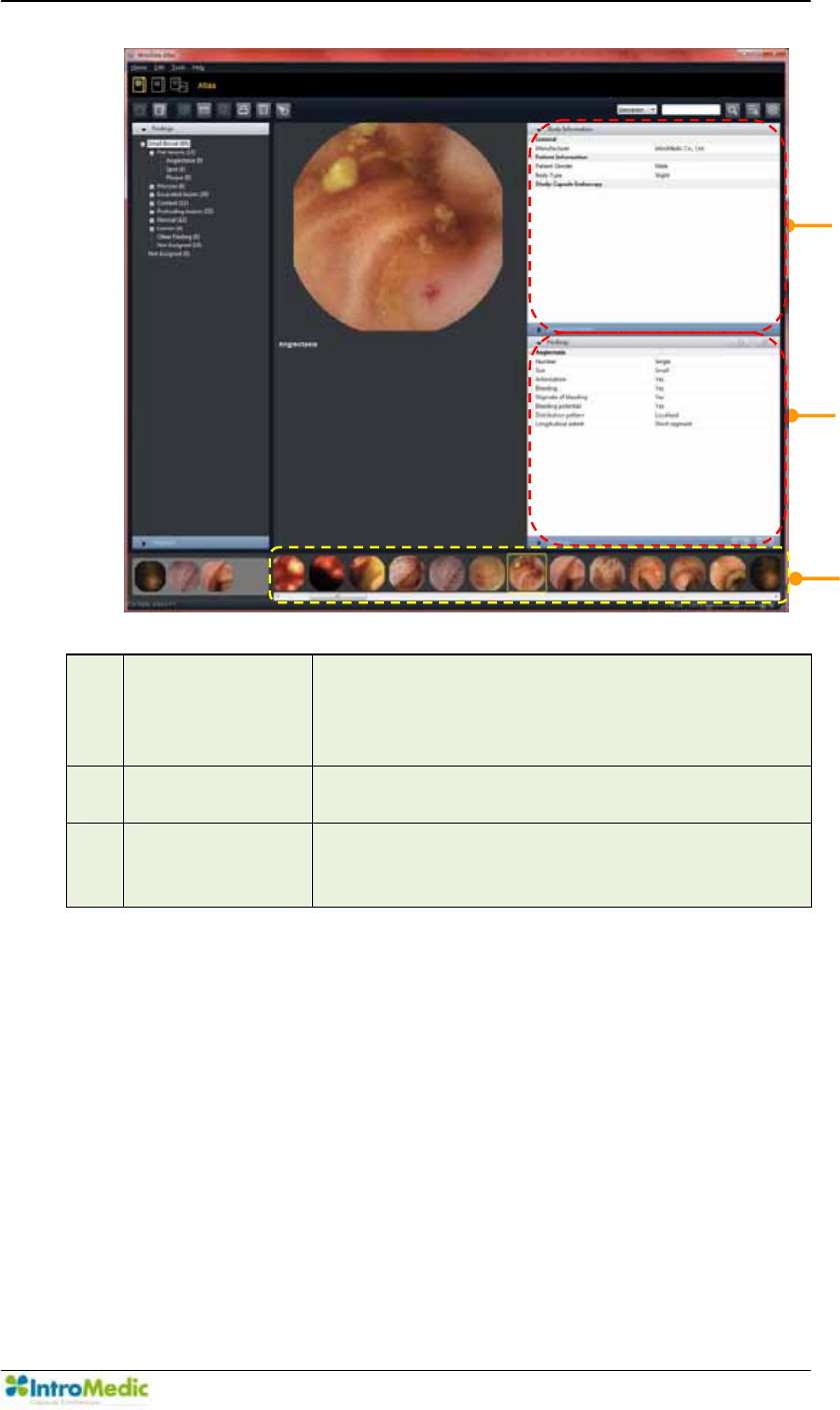
Chapter 4 Using 0LUR9LHZ Software
4-117
Ԩ Study
Information
/ Image
Information
Show the Information of the Atlas Image
ԩ Findings /
Diagnosis
Show the Findings / Diagnosis Information
Ԫ Atlas
Thumbnail
Area(2)
Search the Atlas Image
̺
18
̺
19
̺
17
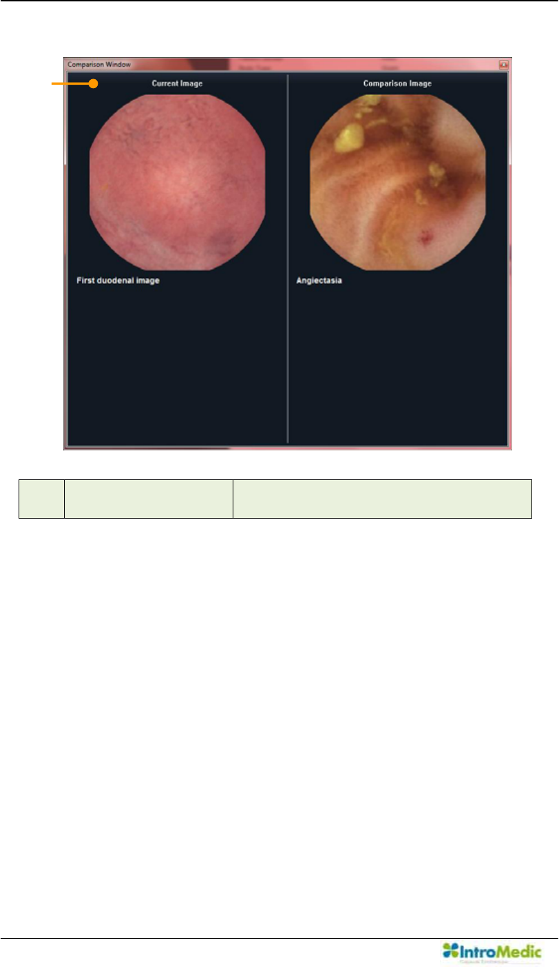
Using MiroView Software Chapter 4
4- 118
ԫ Comparison Window Show the Current Image and
Comparison Image at once.
̺
20
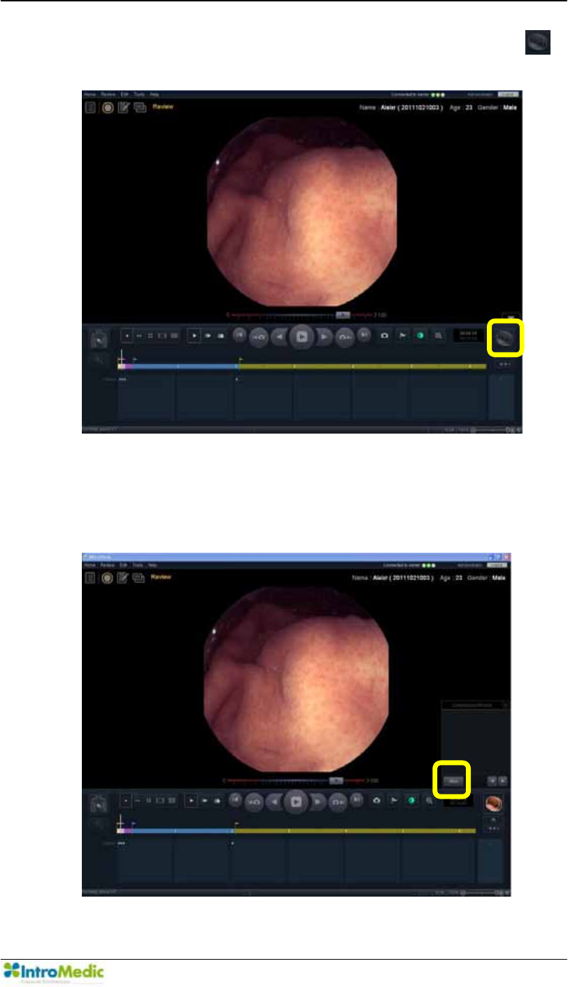
Chapter 4 Using 0LUR9LHZ Software
4-119
To compare a captured image with ATLAS image, click the
(Optional).
6HOHFW DQ LPDJH IURP 0LUR9LHZ Atlas to compare the atlas
image with the captured image for a side by side comparison.
(Option)
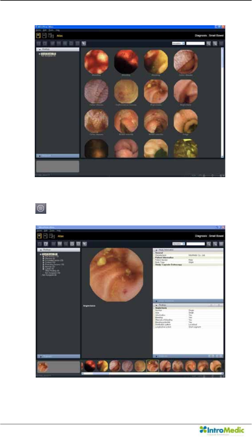
Using MiroView Software Chapter 4
4- 120
Double-click an ATLAS image for selection.
To show the ATLAS image on the comparison window, click the
on the ATLAS mode.
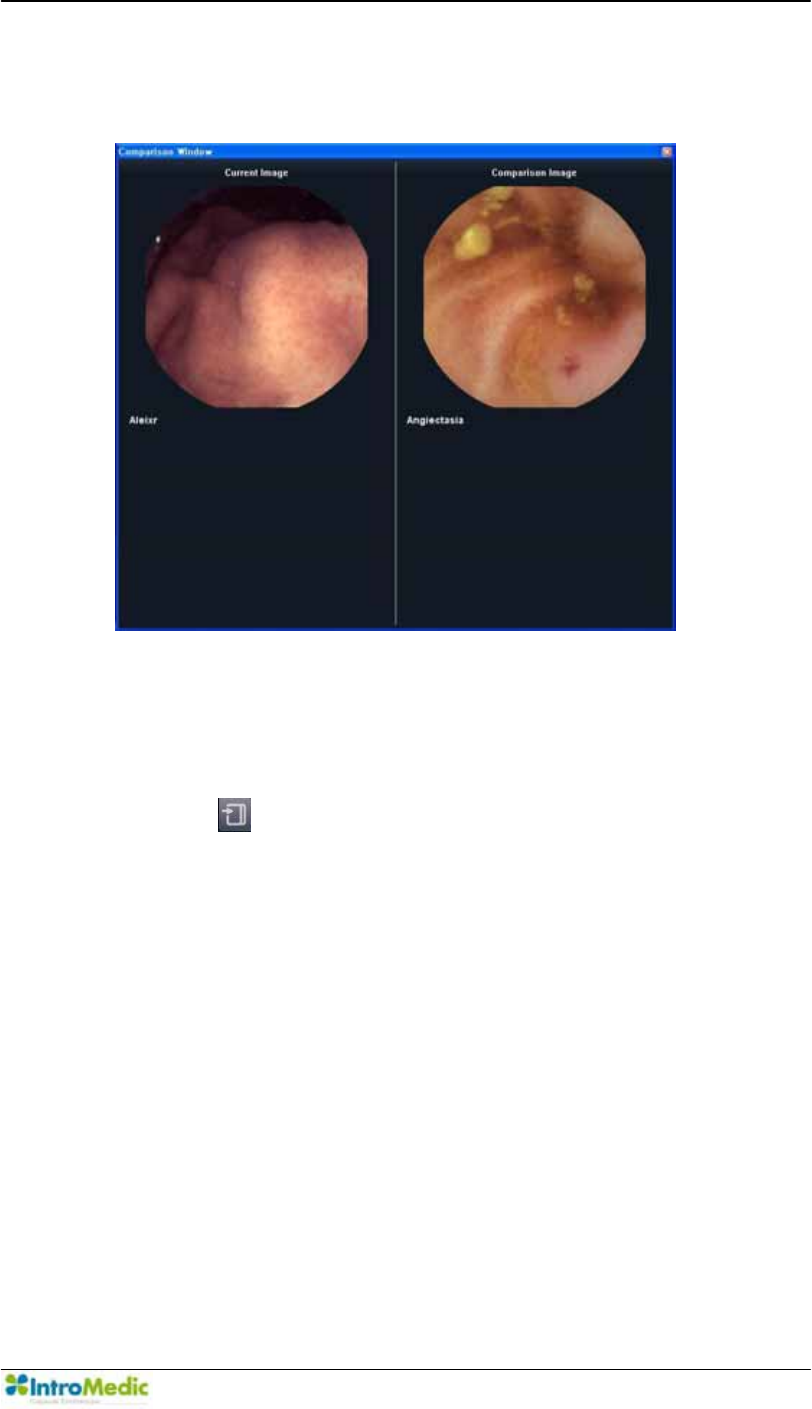
Chapter 4 Using 0LUR9LHZ Software
4-121
The comparison windows will appear. Figure out the current
image and comparison image.
Import Atlas Images from file(s)
The 0LUR9LHZ Software allows the user to import image files for
personal purpose.
- Click the WRRSHQWKHµ2SHQ¶%URZVHU WR ORRNIRUWKHILOHVWR
import.
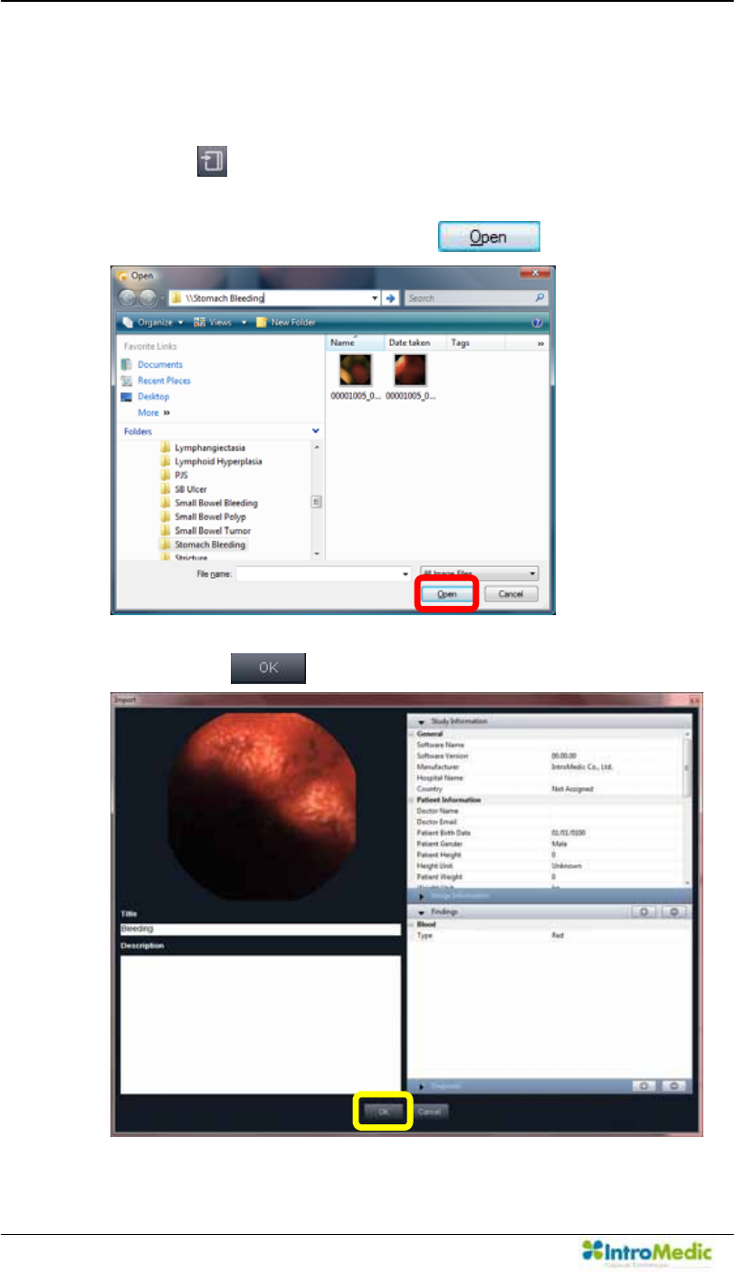
Using MiroView Software Chapter 4
4- 122
Import Atlas Images from file(s)
The 0LUR9LHZSoftware allows the user to import image files for
personal purpose.
- Click the WRRSHQWKHµ2SHQ¶%URZVHU WR ORRNIRUWKHILOHVWR
import.
- Select the file to import and click the .
- &RPSOHWH WKH µ7LWOH¶ µ'HVFULSWLRQ¶ DQG µ,PDJH ,QIRUPDWLRQ¶ ILHOGV
and click the .
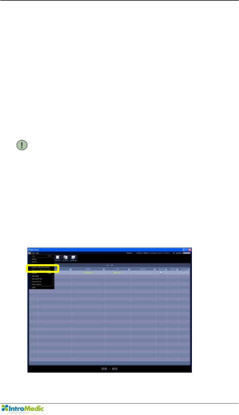
Chapter 4 Using 0LUR9LHZ Software
4-123
4.7 How to import 0LUR9LHZSoftware 1.0 Files
4.7.1 Preparing files for import
5XQWKH0LUR9LHZSoftware 1.0
([SRUW ILOHV E\ FOLFNLQJ µ([SRUW IRU the 0LUR9LHZ ([SUHVV¶
function or back up files by using Backup Mode on the
0LUR9LHZ Software 1.0. Before using the Export to the
0LUR9LHZ Express function, insert DVD media to the DVD
writer or connect the external hard disk or USB flash memory to
the workstation via USB port.
NOTE The 0LUR9LHZ Software supports the
0LUR9LHZ Software Case / Review files, the
0LUR9LHZ H[SUHVV ILOHV (the MiroCam®
Capsule Endoscope System companying
with .MMV) and the 0LUR9LHZ Software 1.0
backup files(.ifo companying with .ict and .frg files)
to import.
Select a patient file from the list to export to the 0LUR9LHZ
Express.
([HFXWHµ([SRUWWRthe 0LUR9LHZ([SUHVV«¶RQWKHPDLQPHQX
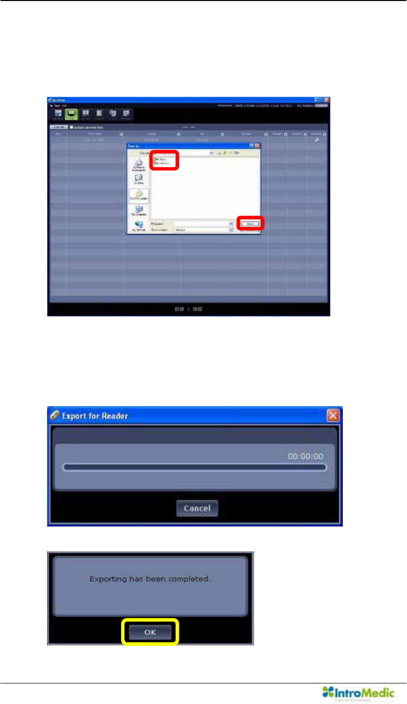
Using MiroView Software Chapter 4
4- 124
,I WKH IRUP µ6DYH $V¶ DSSHDUV OLNH EHORZ VHOHFW WKH ORFDWLRQ WR
H[SRUWDQGILOOLQWKHµ)LOHQDPH¶ILHOGDQGFOLFNµ6DYH¶
Carry out in alphabetical order like following picture.
A window will appear like below and if the function ends
VXFFHVVIXOO\ $ PHVVDJH ZLOO DSSHDU ³([SRUWLQJ KDV EHHQ
FRPSOHWHG´
Ú
Û
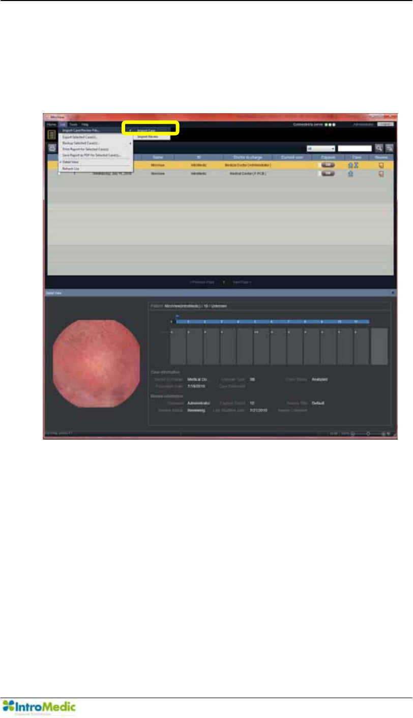
Chapter 4 Using 0LUR9LHZ Software
4-125
4.7.2 Import 0LUR9LHZSoftware 1.0 files
Run the 0LUR9LHZOperator or 0LUR9LHZClient.
([HFXWHWKH¶,PSRUW&DVH5HYLHZ)LOH«-!,PSRUW&DVH¶LQWKHµ/LVW¶
menu
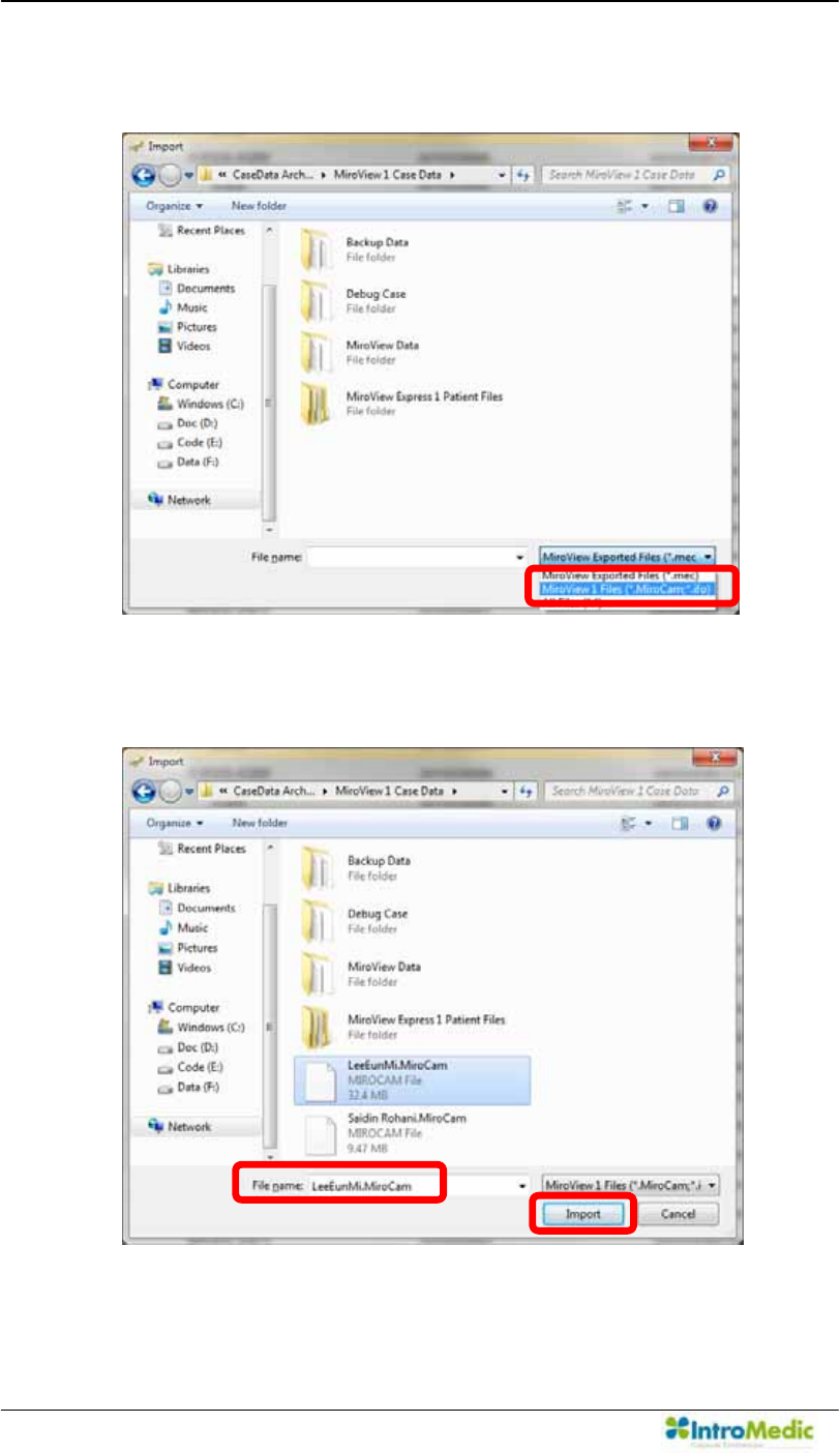
Using MiroView Software Chapter 4
4- 126
Select the 0LUR9LHZ Software 1.0 files from the file extension
drop-down box and look for the file to upgrade
/RRNIRUWKH)LOHZLWKH[WHQVLRQµ0LUR&DP¶DQGFOLFNµImport¶.
Carry out in alphabetical order like following picture.
Ú
Û
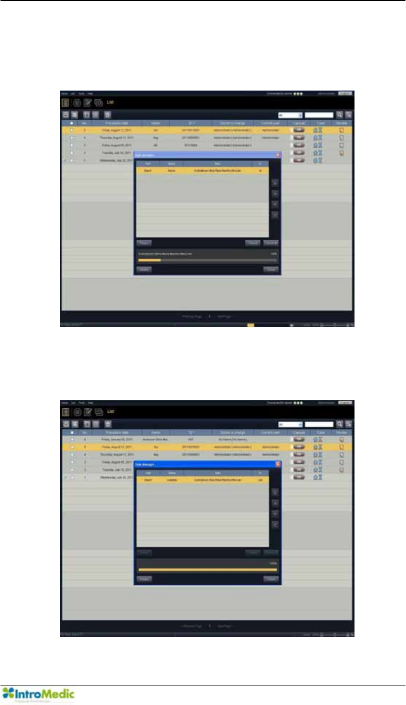
Chapter 4 Using 0LUR9LHZ Software
4-127
Task Manager will appear and will proceed with importation of the
file.
Progress bar will appear.
Upgrading the 0LUR9LHZ Software 1.0 file to the 0LUR9LHZ
Software file will be completed.
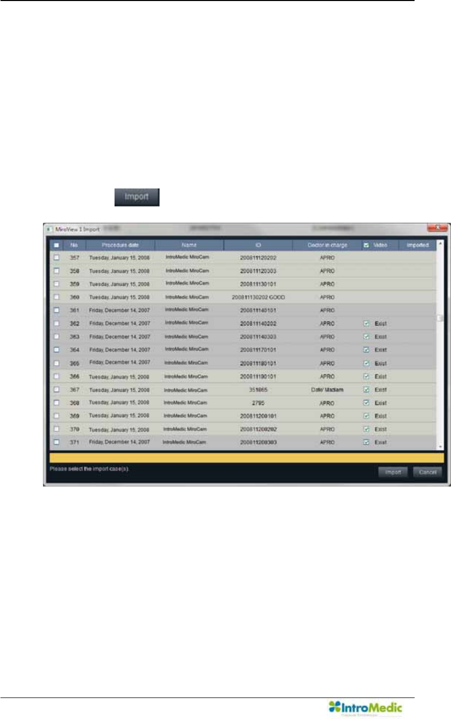
Using MiroView Software Chapter 4
4- 128
4.7.3 0LUR9LHZSoftware 1.0 files Batch Import
If the 0LUR9LHZSoftware 1.0 is already installed on the workstation,
user can use the 0LUR9LHZ Software 1.0 files Batch Import
function via <Menu -> Tools -> Import from the 0LUR9LHZSoftware
1.0> in 0LUR9LHZOperator (or <Menu -> Home -> Import from the
0LUR9LHZ Software 1.0> in the 0LUR9LHZ Client) so that
0LUR9LHZcan use the imported cases. Choose the cases to import
and click the .
To import cases without video file, uncheck the check box on the
Video column.
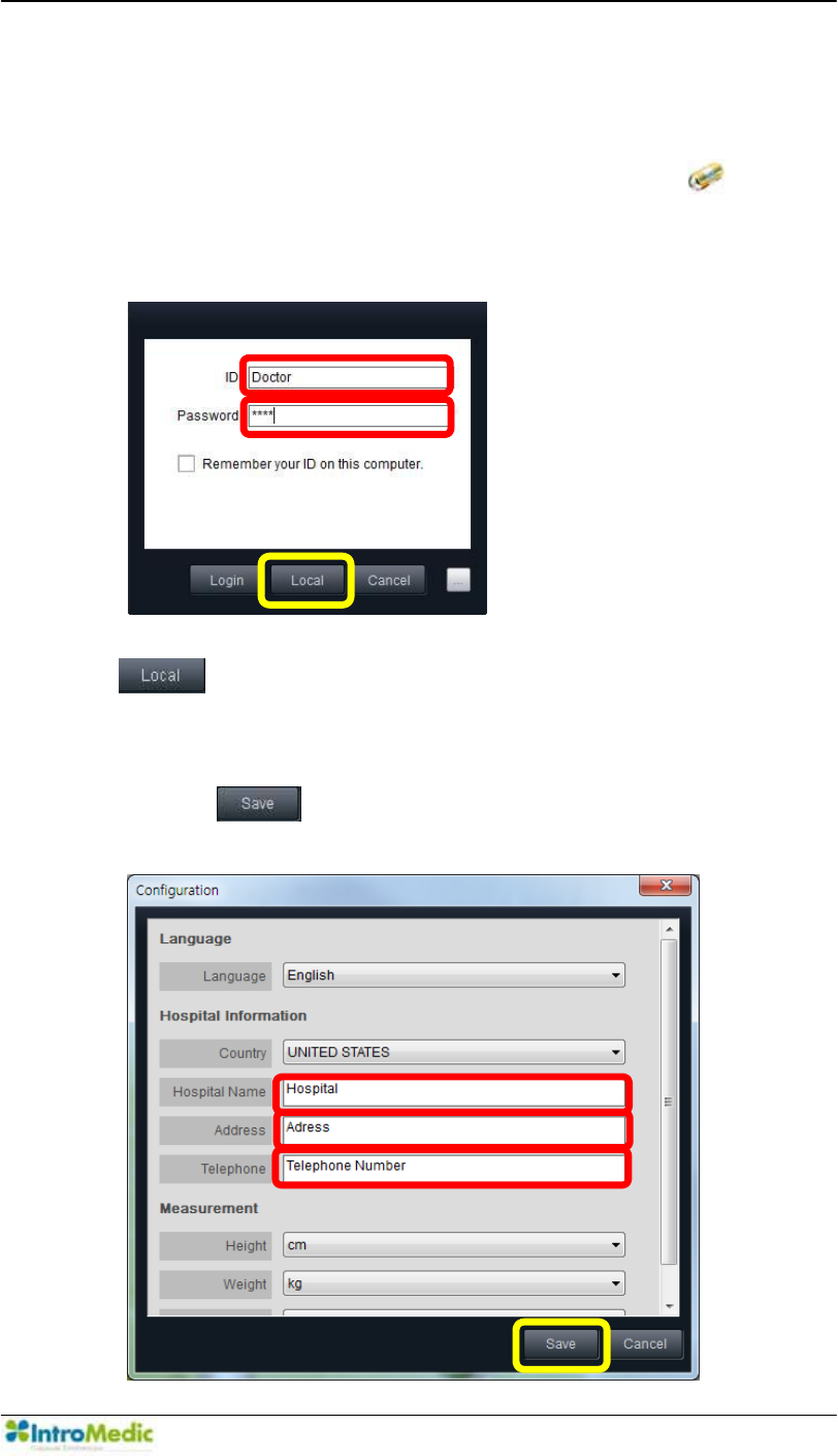
Chapter 4 Using 0LUR9LHZ Software
4-129
4.7.4 Using 0LUR9LHZ Client at Local PC without connecting to
0LUR9LHZServer
Run the 0LUR9LHZ Client by double-clicking the on the
desktop or from the Windows Start-up menu. Log in.
Carry out in alphabetical order like following picture.
*If running the 0LUR9LHZ Client as Local Mode, click the
on the Log-in screen.
$W WKH ILUVW UXQQLQJ RI µ/RFDO 0RGH¶ WKH ZLQGRZ ZLOO DSSHDU OLNH
below. Input the appropriate values in to the empty fields and
click the to proceed.
Carry out in alphabetical order like following picture.
Ú
Û
Ü
Ý
Ú
Û
Ü
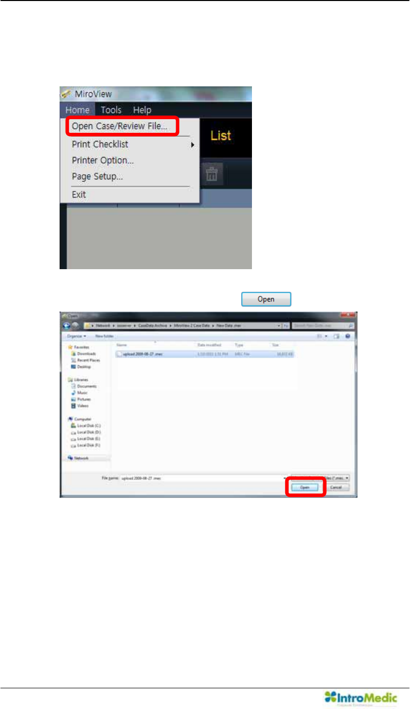
Using MiroView Software Chapter 4
4- 130
Open the Case/Review via Menu Æ Home Æ Open Case/Review
ILOH«
Choose a file to open and click the .
After completely reviewing the file, save the review via Menu
Æ
Home
Æ
Save Active Review so that the user can import the
edited review file on the 0LUR9LHZServer in the future.

5
8VLQJ0LUR9LHZ579

8VLQJ0LUR9LHZ579 Chapter 5
5- 2
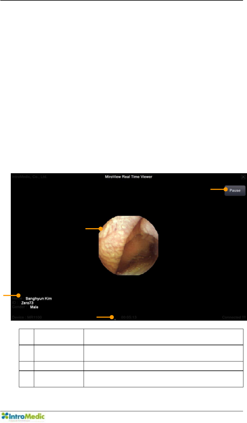
Chapter 8VLQJ0LUR9LHZRTV
5-3
5. 86,1*0,529,(:579
The 0LUR9LHZ 579 D software application of the MiroCam® System
Real-time Viewer, consist of a data transmission module that directly
receives the image data from the MiroCam® Receiver and an output
module for image display.
5.1 Overview
The MiroView579VRIWZDUHFDQEHLQVWDOOHGRQDQ\PRELOHSODWIRUP
&OLFN WKH FRUUHVSRQGLQJ LFRQ RQ WKH GHVNWRS WR ODXQFK WKH 0LUR9LHZ
RTV.
Basic Screen Layout
c Patient
Information
Display patient name, ID, gender and age
d Operation
Button
Change the 0LUR9LHZ 579 RSHUDWLRQ VWDWXV
between start, pause and resume.
e Main Display Display captured image.
f Time Display Indicates the MiroCam® Capsule endoscopy
procedure time.
£
¢
¤
¥

8VLQJ0LUR9LHZ579 Chapter 5
5- 4
Recommended Hardware Specification
OS: Windows Vista (32 bit), Windows XP (32 bit),
Windows7 (32 bit)
CPU: Atom N450(1.66GHz) or higher
Memory: 1GB or higher
Display Adaptor: Windows Compatible
Hard Disk: 80GB memory space available
Monitor Resolution: 1024 X 600 or higher
Monitor Contrast : Windows Compatible
In compliance with IEC60950-1 or IEC60601-1
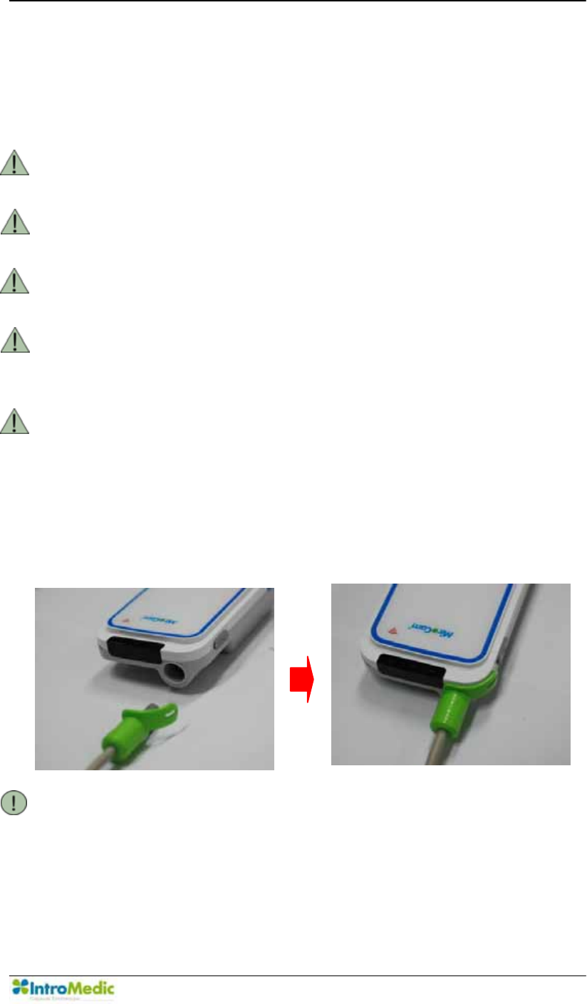
Chapter 8VLQJ0LUR9LHZRTV
5-5
5.2 8VLQJ0LUR9LHZ579
5.2.1 %HIRUH8VLQJ0LUR9LHZ579
Installing tKH0LUR9LHZ579VRIWZDUHon a mobile PC.
WARNING Only recharge the Mobile PC batteries when MiroCam®
Receiver does not connect to the Mobile PC.
WARNING For safe use of the Mobile PC, please refer to the Mobile
PC User Manual.
WARNING DO NOT use the 0LUR9LHZ579VRIWZDUHDQGthe Mobile
PC before upgrading MR1000.
WARNING DO NOT upgrade MiroCam® Receiver during the
MiroCam® Capsule endoscopy procedure, it may result
loss of image data.
WARNING UVH WKH 0LUR9LHZ RTV Software to check if the
MiroCam® Capsule entered to the duodenum, small bowl;
during a capsule endoscopy procedure. Thus, prior to
UXQQLQJ WKH 0LUR9LHZ RTV software, please make sure
that the MiroCam® Capsule endoscopy procedure has
been undergone.
Connect the data cable of the Real-time Viewer to the MiroCam®
Receiver.
NOTE The data cable for the MiroView579KDVQRFRYHUIRUWKH
USB port on the MiroCam® Receiver.
Follow the MiroCam® Capsule endoscopy procedure.
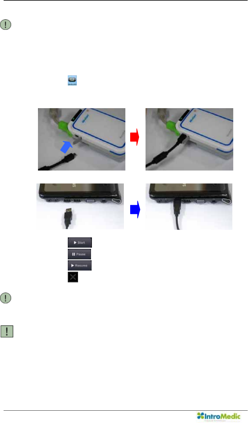
8VLQJ0LUR9LHZ579 Chapter 5
5- 6
NOTE For more information on the MiroCam® Capsule endoscopy
procedure, please refer to Chapter 3, Performing Capsule
Endoscopy.
5.2.2 Starting 0LUR9LHZ RTV
Switch on the Mobile PC.
Click the on the screen to launch the 0LUR9LHZ579
Connect the small side of the USB cable to the MiroCam®
Receiver.
Connect the large side of the USB cable to the Mobile PC.
Click the to start image display
Click the to stop image display
Click the to restart image display
Click the on the top-ULJKWWRFORVHWKH0LUR9LHZ579
NOTE To Start, Pause, and Resume use the same button. The
function (Start, Pause or Resume) changes based upon the
status of the 0LUR9LHZ579VRIWZDUH
CAUTION DO NOT disconnect the MiroCam® Receiver while the RTV
software is running. If the MiroCam® Receiver is
disconnected during use, the software may need to be
restarted.

Chapter 8VLQJ0LUR9LHZRTV
5-7
NOTE If an error message appears while using the 0LUR9LHZ
RTV, reconnect the USB cable between the MiroCam®
Receiver and the Mobile PC
5.2.3 After Using 0LUR9LHZ RTV
Disconnect USB cable between the MiroCam® Receiver and the
Mobile PC.
Continue MiroCam® Capsule endoscopy procedure.

8VLQJ0LUR9LHZ579 Chapter 5
5- 8

6
Using :LUHOHVV0LUR9LHZ579L

Using Wireless MiroView RTVi Chapter 6
6- 2

Chapter 6 Using Wireless MiroView RTVi
6-3
6. USING :,5(/(660,529,(:579L
The :LUHOHVV 0LUR9LHZ 579L, a software application of MiroCam®
System Real-time Viewer, consist of a data transmission module that
directly receives the image data from the MiroCam® Receiver and an
output module for image display. The :LUHOHVV 0LUR9LHZ 579L
receives image data via Wi-Fi channel.
6.1 Overview
The :LUHOHVV0LUR9LHZ579L software can be installed on iOS running
on iPad / iPhone. Click the corresponding on the desktop to launch the
:LUHOHVV0LUR9LHZ579L.
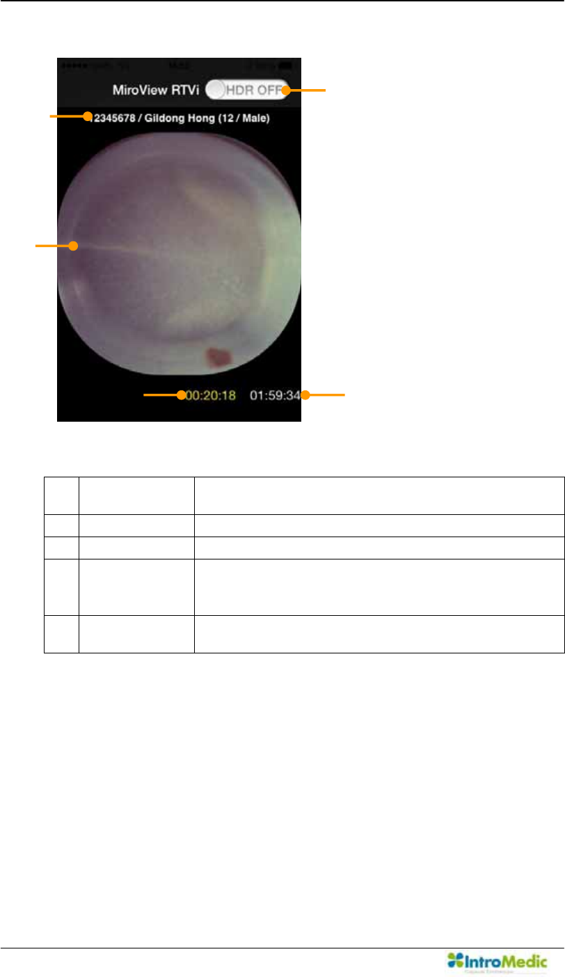
Using Wireless MiroView RTVi Chapter 6
6- 4
6.1.1 Basic Screen Layout ± iPhone
c Patient
Information
Display patient name, ID, gender and age
d HDR Button High Dynamic Range Image Button
e Main Display Display captured image.
f Wi-Fi
Operation
Time
Indicates the MiroCam® Wi-Fi operation time
ྜྷ Recording
time
Indicates the MiroCam® Capsule recording time.
£
¢
¤
¥ ¦
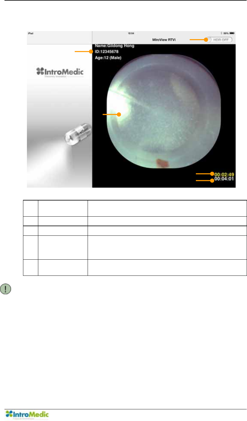
Chapter 6 Using Wireless MiroView RTVi
6-5
6.1.2 Basic Screen Layout ± iPad
c Patient
Information
Display patient name, ID, gender and age
d HDR Button High Dynamic Range Image Button
e Main Display Display captured image.
f Wi-Fi
Operation
Time
Indicates the MiroCam® Wi-Fi operation time
ྜྷ Recording
time
Indicates the MiroCam® Capsule recording time.
NOTE If turning the iPad upright as Portrait View, the MiroCam®
Receiver List will disappear from the Main Display to be
enlarged.
6.1.3 Recommended Hardware Platform
iPhone 3G, 3GS, 4, 4S, 5
iPad I, II (with only Wi-Fi)
¢
£
¤
¥
¦
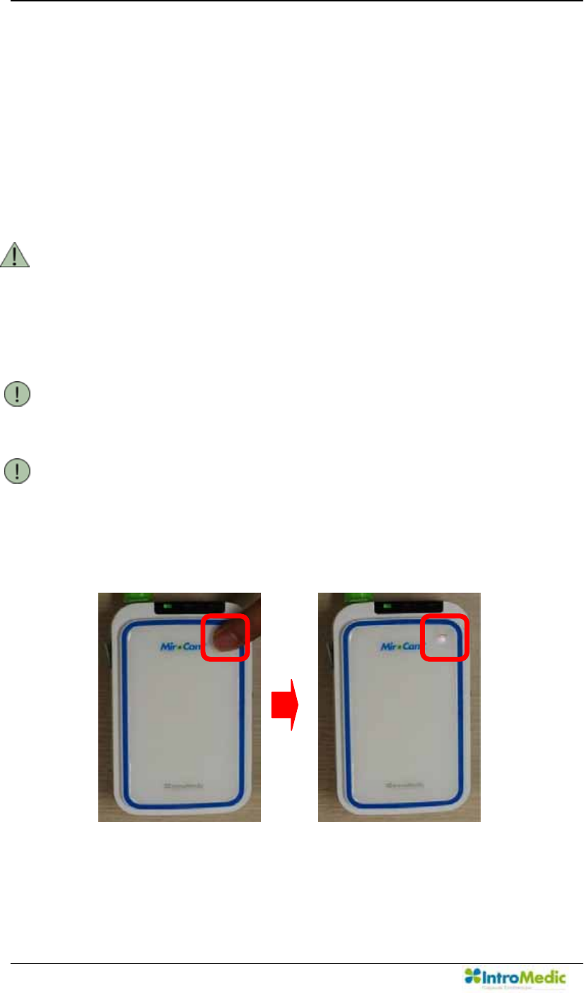
Using Wireless MiroView RTVi Chapter 6
6- 6
6.2 Using :LUHOHVV0LUR9LHZ579L
6.2.1 Before Using :LUHOHVV0LUR9LHZ579L
Installing tKH :LUHOHVV 0LUR9LHZ 579L VRIWZDUH on iOS on
iPhone or iPad.
The effective distance between the MiroCam® Receiver and
iPhone or iPad is within 3m.
WARNING Use the :LUHOHVV0LUR9LHZ579L Software to check if the
MiroCam® Capsule entered to the duodenum and small
bowl during a capsule endoscopy procedure. Thus, prior to
running the :LUHOHVV 0LUR9LHZ 579L software, please
make sure that the MiroCam® Capsule endoscopy
procedure has been undergone.
NOTE For more information on the MiroCam® Capsule endoscopy
procedure, please refer to Chapter 3, Performing Capsule
Endoscopy.
NOTE When the :LUHOHVV 0LUR9LHZ 579L run at first, network
configuration for iPhone or iPad is required.
6.2.2 Turn on the Wi-Fi function of the MiroCam® Receiver.
Press the Wi-Fi switch of MiroCam® Receiver.
Keep pressing it until the buzzer sounds.
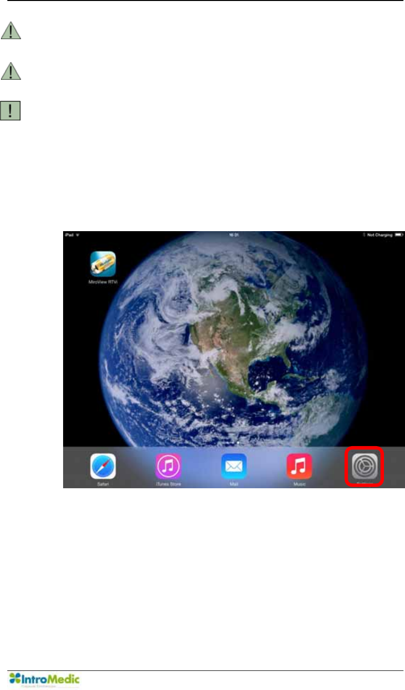
Chapter 6 Using Wireless MiroView RTVi
6-7
WARNING DO NOT press the Wi-Fi switch when the buzzer sounds. It
can cause the lost of captured images.
WARNING The Wi-Fi switch of MiroCam® Receiver can be turned on
involuntarily. Therefore, be careful it is not turned on.
WARNING The MiroView RTVi application can only be used for a
total of 30 minutes during the entire MiroCam® Capsule
Endoscopy Procedure.
6.2.3 Wireless MiroView579L.
Run the Settings for the iOS.
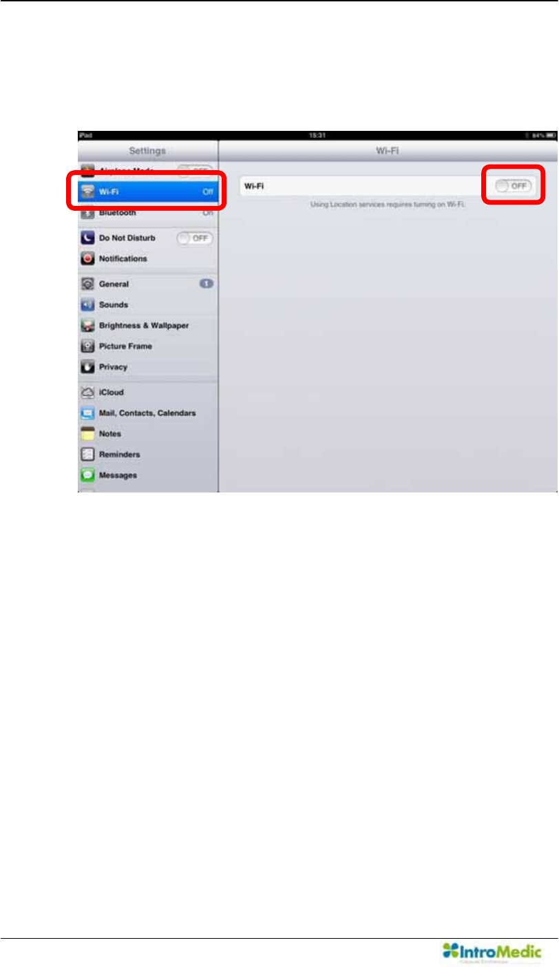
Using Wireless MiroView RTVi Chapter 6
6- 8
Turn on the Wi-Fi. If Wi-Fi is already turned on, please turn it off
and turn it back on. Carry out in alphabetical order like following
picture.
Û
Ú
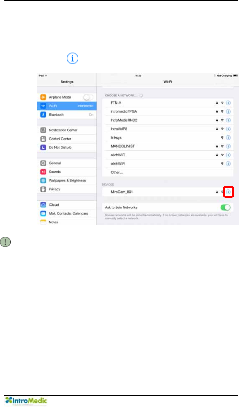
Chapter 6 Using Wireless MiroView RTVi
6-9
6.2.4 TCP/IP Configuration (for the first time to connect a MiroCam®
Receiver access point: AP)
Check a network with SSID of MiroCam_xxx in the network list.
Click the on the SSID (MiroCam_xxx).
NOTE TCP/IP configuration is needed once at first.
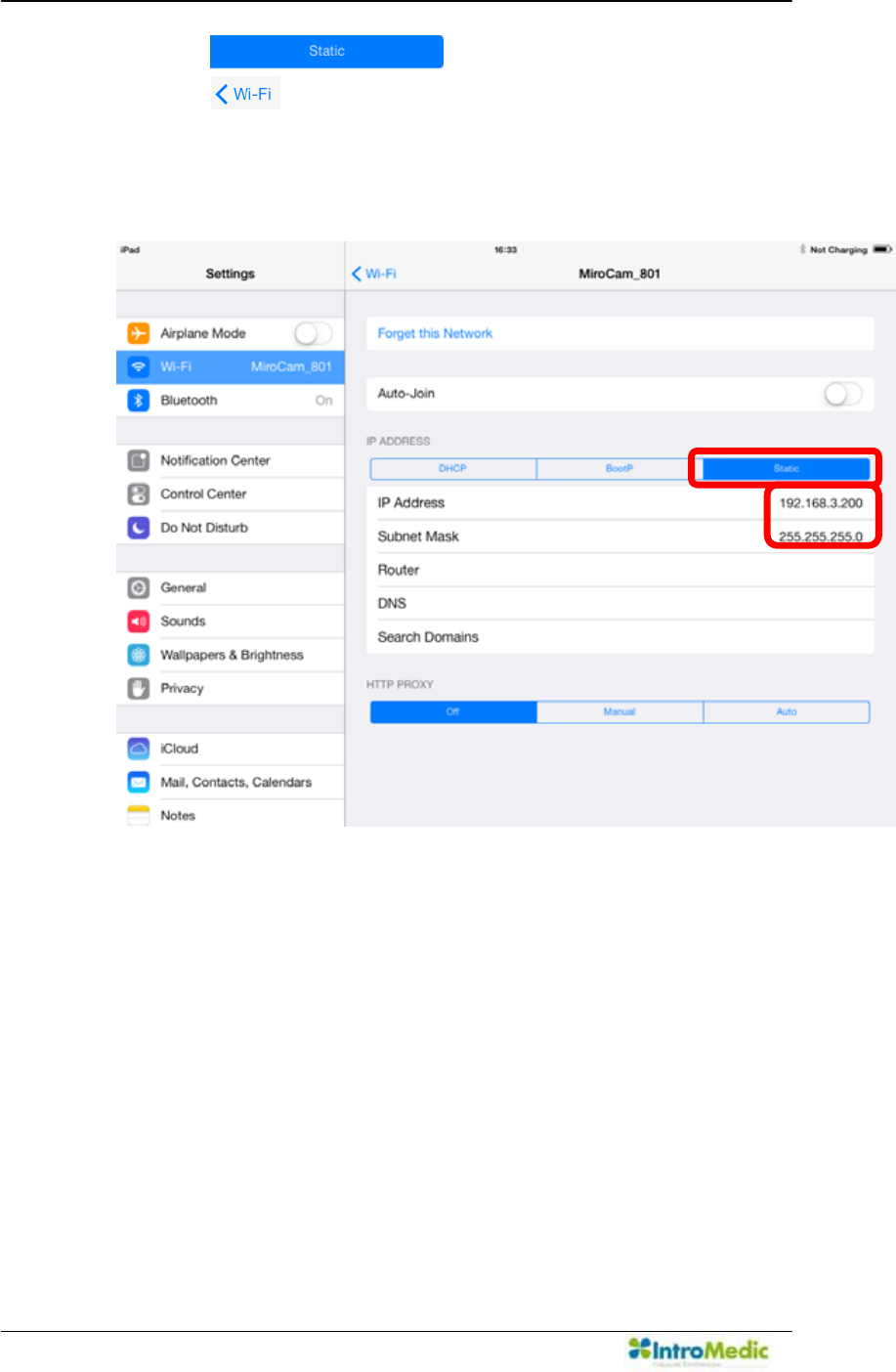
Using Wireless MiroView RTVi Chapter 6
6- 10
Click the .
Click the on the top-left after entering the IP Address and
Subnet Mask. (Setup as Static; IP Address: 192.168.3.200,
Subnet Mask:255.255.255.0)
Carry out in alphabetical order like following picture.
Ú
Û
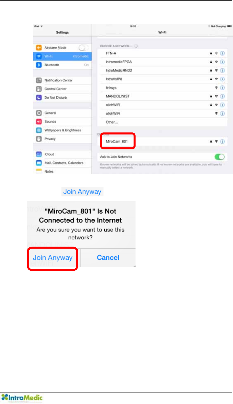
Chapter 6 Using Wireless MiroView RTVi
6-11
Click the SSID.
Click the .
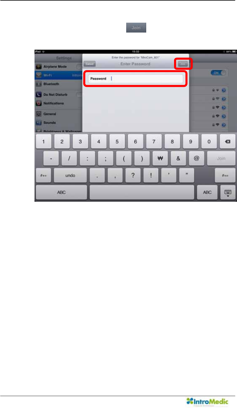
Using Wireless MiroView RTVi Chapter 6
6- 12
Enter the password '1234567890' in the field with instruction of
system. Afterward, click the .Carry out in alphabetical
order like following picture.
Press home button when network connection finished.
Ú
Û
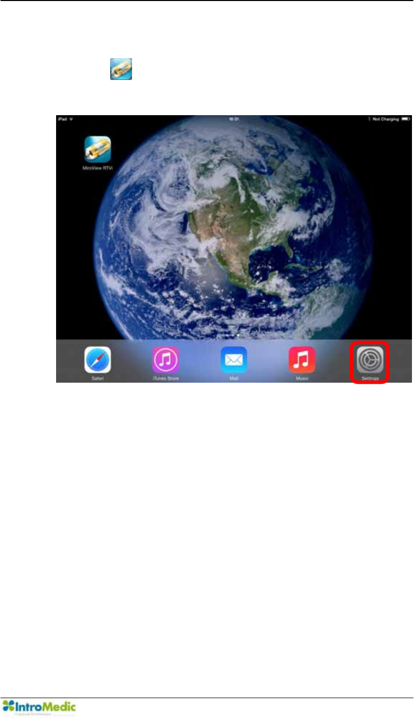
Chapter 6 Using Wireless MiroView RTVi
6-13
6.2.5 Running :LUHOHVV0LUR9LHZ579L
Click the on the desktop to launch the :LUHOHVV0LUR9LHZ
RTVi.
The Splash window will appear for a while and then will disappear.
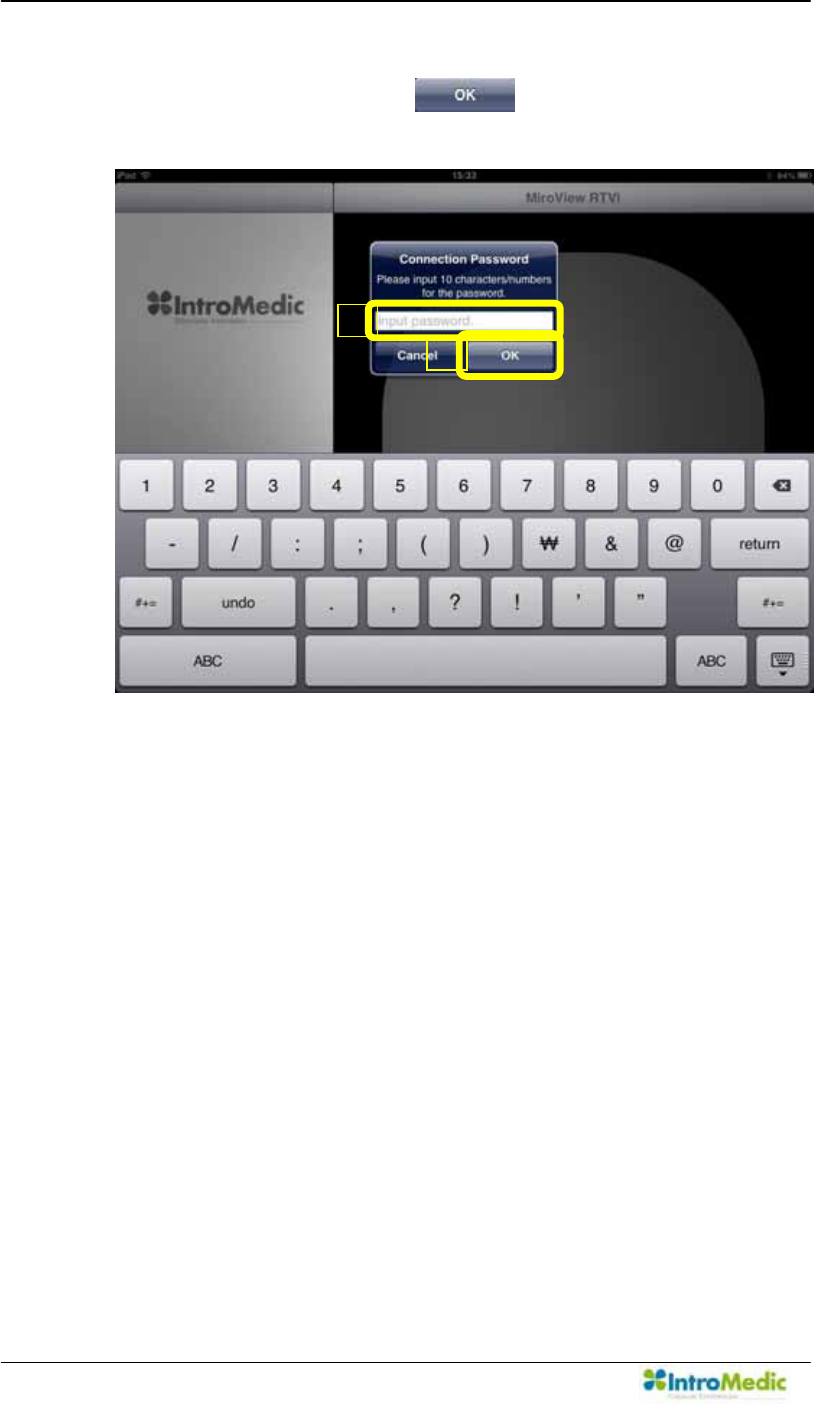
Using Wireless MiroView RTVi Chapter 6
6- 14
Enter the password '1234567890' in the field with instruction of
system. Afterward, click the . Carry out in alphabetical
order like following picture.
Ú
Û
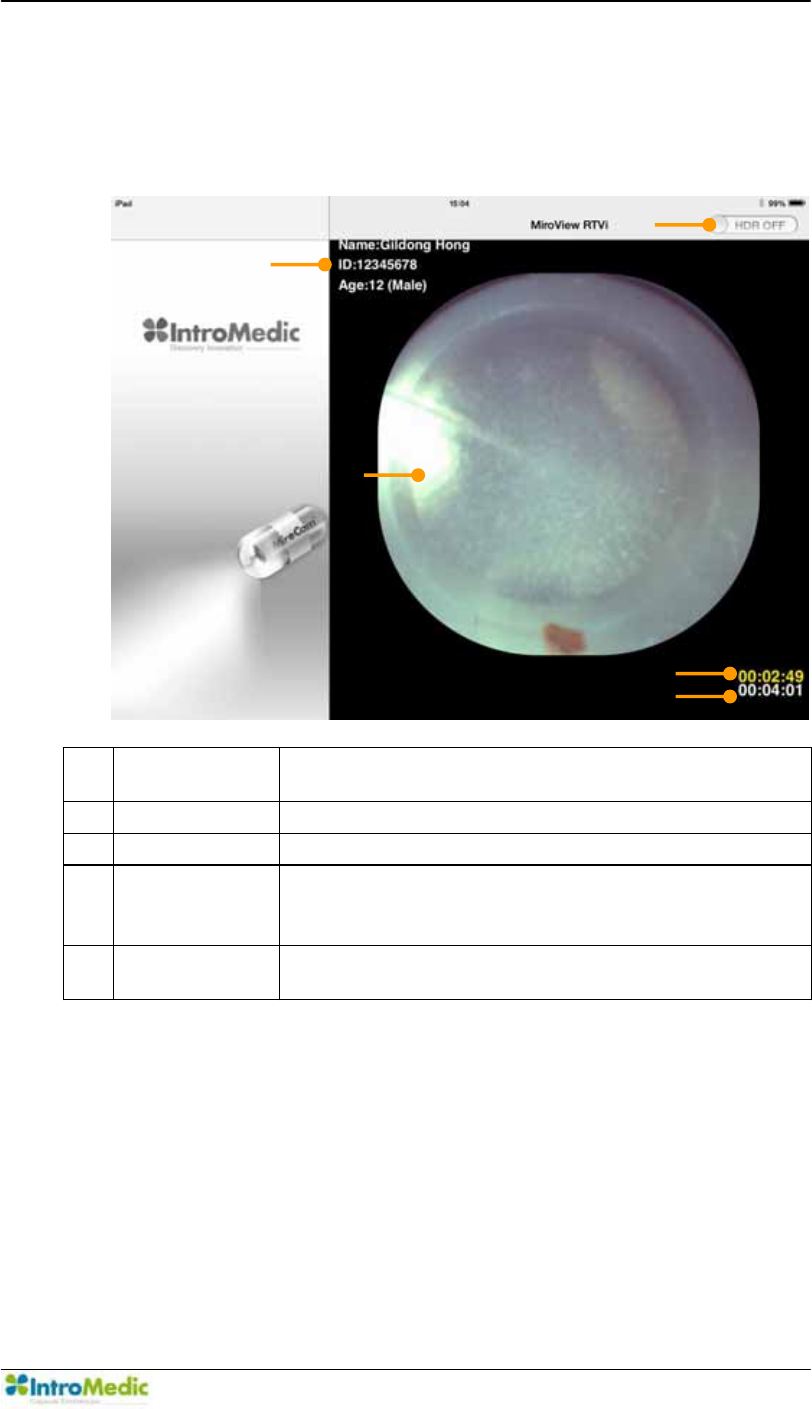
Chapter 6 Using Wireless MiroView RTVi
6-15
Check whether Patient Information, MiroCam® Receiver Scan
Button, Main Display, Wi-Fi Operation Time and Recording time
are displayed normally.
c Patient
Information
Display patient name, ID, gender and age
d HDR Button High Dynamic Range Image Button
e Main Display Display captured image.
f Wi-Fi
Operation
Time
Indicates the MiroCam® Wi-Fi operation time
ྜྷ Recording
time
Indicates the MiroCam® Capsule recording time.
¢
£
¤
¥
¦
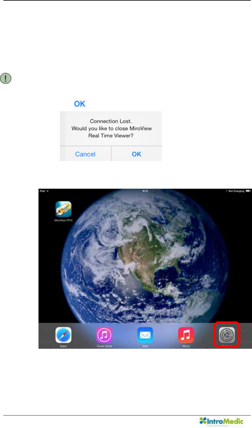
Using Wireless MiroView RTVi Chapter 6
6- 16
6.2.6 After Using :LUHOHVV0LUR9LHZ579L
7R FORVH WKH :LUHOHVV 0LUR9LHZ 579L press the home button
and then check whether the Wi-Fi light of the MiroCam®
Receiver is off.
NOTE If MiroCam® Receiver is turned off, following window will
appear after about 10 seconds. To Close this window, click
the .
Run the Settings for the iOS.
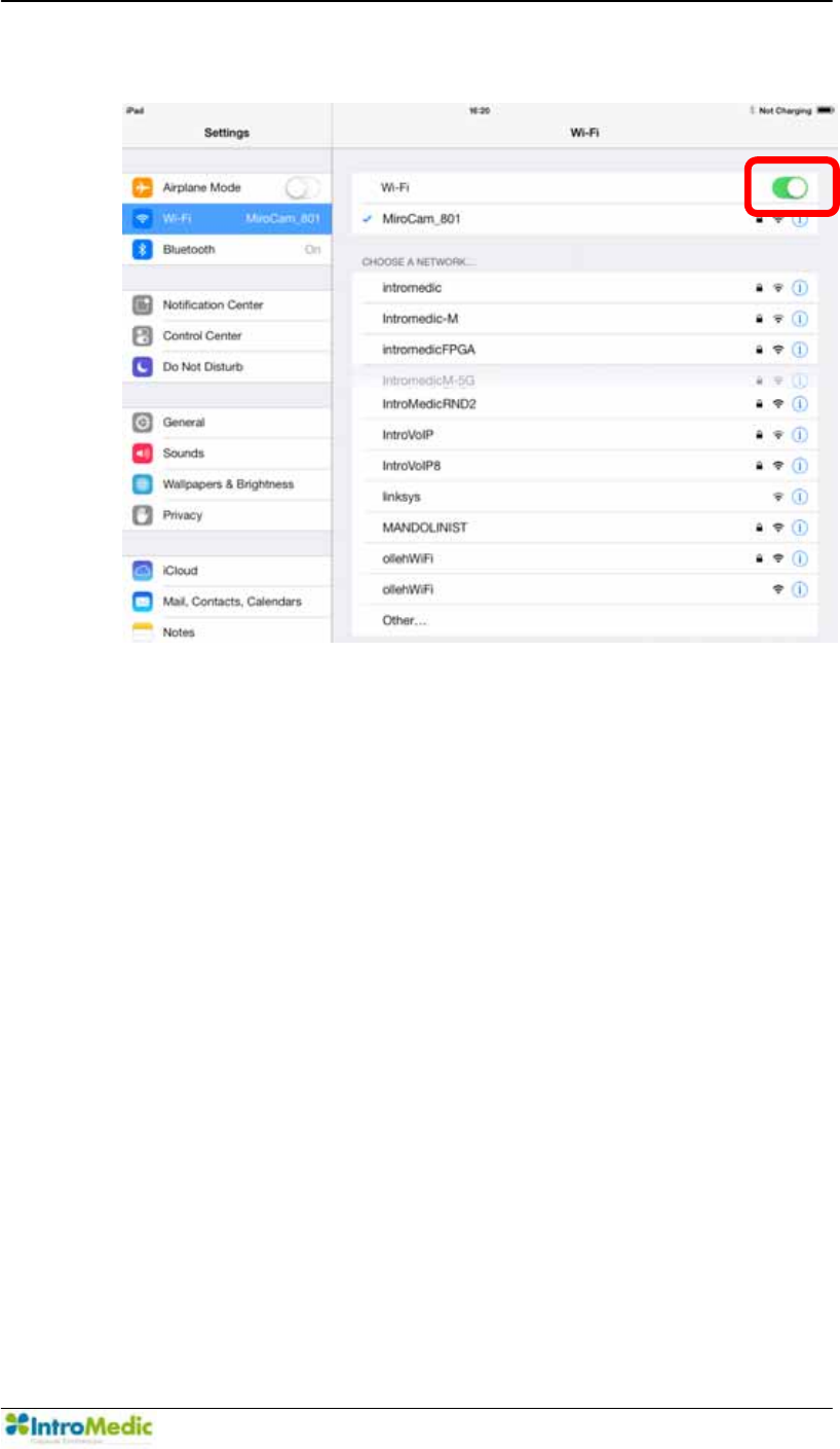
Chapter 6 Using Wireless MiroView RTVi
6-17
Turn Wi-Fi off and turn it back on.

Using Wireless MiroView RTVi Chapter 6
6- 18

A
Appendix

Case Form Report
A
- 2

Case Form Report
A
-3
Trial ID : Version No. : 1.0 : 30/07/2007
CASE REPORT FORM
Subject No.: Subject Initials : Center No.:
Principal
Investigator :
Center Name :
Address :
Telephone No. :
Fax No. :
E-mail :
CONFIDENTIAL

Case Form Report
A
- 4
Trial ID :
Version No. : 1.0 :
30/07/2007
Screening
Subject No.: Subject Initials : Center No.:
Date of Informed consent signed
D
M
M
Y Y Y Y
Inclusion Criteria
Yes No N/A
1. Informed consent form voluntarily signed
2. Male / Female subject of age 19 years~70 years.
If there is one or more PDUNRIµ1R¶\RXVKDOOEHFRQWUDGLFWHGIRUWKLVFOLQLFDOWHVW
CONFIDENTIAL

Case Form Report
A
-5
Trial ID : Version No. : 1.0 : 30/07/2007
Screening
Subject No.: Subject Initials : Center No.:
Date of visit :
D M
M
Y Y Y Y
Exclusion Criteria
Yes No N/A
1. Do you have a gastrointestinal disorder (suspected
malignantlesions or gastrointestinal obstructive disorders,
perforation, stenosis or fistula)?
2. Do you have a cardiovascular disorder (dysrhythemia, trouble
with cardiac conduction system, hypertension(high blood
pressure) or ischemic heart disease)?
3. Have you been diagnosed of cardiac insufficiency, angina
pectoris or cardiac arrest (heart attack) in recent 6 months?
4. Are you with (or implanted) medical devices such as cardiac
pacemaker or defibrillator?
5. Do you have a swallowing disorder?
6. Do you have delayed gastric emptying or serious gastric
disorder?
7. Are you a pregnant or nursing woman, or a woman of child
bearing potential?
8. Are you an infant or epileptic? Are you easily affected by
electronic waves?
9. Do you have several small bowel diverticulums ?
10. Did you fail to obtain a voluntary agreement?
11. Are you judged unqualified for this test by doctors or nurses?
,IWKHUHLVRQHRUPRUHPDUNRIµ<HV¶\RXVKDOOEHFRQWUDGLFWHGIRUWKLVFOLQLFDOWHVW
CONFIDENTIAL

Case Form Report
A
- 6
EC Representative
SeDa S.p.A
20090 Trezzano sul Naviglio(MI),
Via Toistoi, 7 Italy
Office: +39-02-484241
Mobile: +39-02-48424290
IntroMedic Co.,Ltd.
Suite 1104, E&C Venture Dream Tower 6-Cha
197-28 Guro-Dong, Guro-Gu, Seoul, KOREA 152-719
Tel : +82-2-801-9300
Fax : +82-2-801-9330
http://www.intromedic.com
e-mail: helpdesk@intromedic.com 0120
Disposal of Old
Electrical &
Electronic
Equipment
Applicable in the
European Union
and other
European
countries with
separate collection
systems
CAUTION: Federal (U.S.A) law restricts this device to sale by or on
the order of a physician.
)&& 127,&(
7KHGHYLFHFRPSOLHVZLWK3DUWRIWKH)&&5XOHV2SHUDWLRQLVVXEMHFWWRWKH
FRQGLWLRQ WKDW WKLV GHYLFH GRHV QRW FDXVH KDUPIXO LQWHUIHUHQFH
127( 7KLV HTXLSPHQW KDV EHHQ WHVWHG DQG IRXQG WR FRPSO\ ZLWK WKH OLPLWV IRU D
&ODVV % 'LJLWDO 'HYLFH SXUVXDQW WR 3DUW RI WKH )&& 5XOHV 7KHVH OLPLWV DUH
GHVLJQHG WR SURYLGH UHDVRQDEOH SURWHFWLRQ DJDLQVW KDUPIXO LQWHUIHUHQFH LQ D
UHVLGHQWLDO LQVWDOODWLRQ 7KLV HTXLSPHQW JHQHUDWHV XVHV DQG FDQ UDGLDWH UDGLR
IUHTXHQF\ HQHUJ\ DQG LI QRW LQVWDOOHG DQG XVHG LQ DFFRUGDQFH ZLWK WKH LQVWUXFWLRQ
PD\ FDXVH KDUPIXO LQWHUIHUHQFH WR UDGLR FRPPXQLFDWLRQ +RZHYHU WKHUH LV QR
JXDUDQWHH WKDW LQWHUIHUHQFH ZLOO QRW RFFXU LQ D SDUWLFXODU LQVWDOODWLRQ ,I WKLV
HTXLSPHQW GRVH FDXVH KDUPIXO LQWHUIHUHQFH WR UDGLR RU WHOHYLVLRQ UHFHSWLRQ ZKLFK
FDQ EH GHWHUPLQHG E\ WXUQLQJ WKH HTXLSPHQW RII DQG RQ WKH XVHU LV HQFRXUDJHG WR
WU\ WR FRUUHFW WKH LQWHUIHUHQFH E\ RQH RU PRUH RI WKH IROORZLQJ PHDVXUHV
5HRULHQW RU UHORFDWH WKH UHFHLYLQJ DQWHQQD ,QFUHDVH WKH VHSDUDWLRQ EHWZHHQ WKH
HTXLSPHQW DQG UHFHLYHU &RQQHFW WKH HTXLSPHQW LQWR DQ RXWOHW RQ D FLUFXLW
GLIIHUHQW IURP WKDW WR ZKLFK WKH UHFHLYHU LV FRQQHFWHG &RQVXOWWKHGHDOHURUDQ
H[SHULHQFHG UDGLR79 WHFKQLFLDQ IRU KHOS
&DXWLRQ
$Q\ FKDQJHV RU PRGLILFDWLRQV LQFOXGLQJ WKH DQWHQQD PDGH WR WKLV GHYLFH WKDW DUH
QRW H[SUHVVO\ DSSURYHG E\ WKH PDQXIDFWXUHU PD\ YRLG WKH XVHUឧV DXWKRULW\ WR
RSHUDWH WKH HTXLSPHQ