Intuitive Surgical CHB01 RFID TRANSCEIVER 3D-HD CAMERA HEAD User Manual da Vinci Si
Intuitive Surgical, Inc. RFID TRANSCEIVER 3D-HD CAMERA HEAD da Vinci Si
Contents
- 1. User Manual Part 1
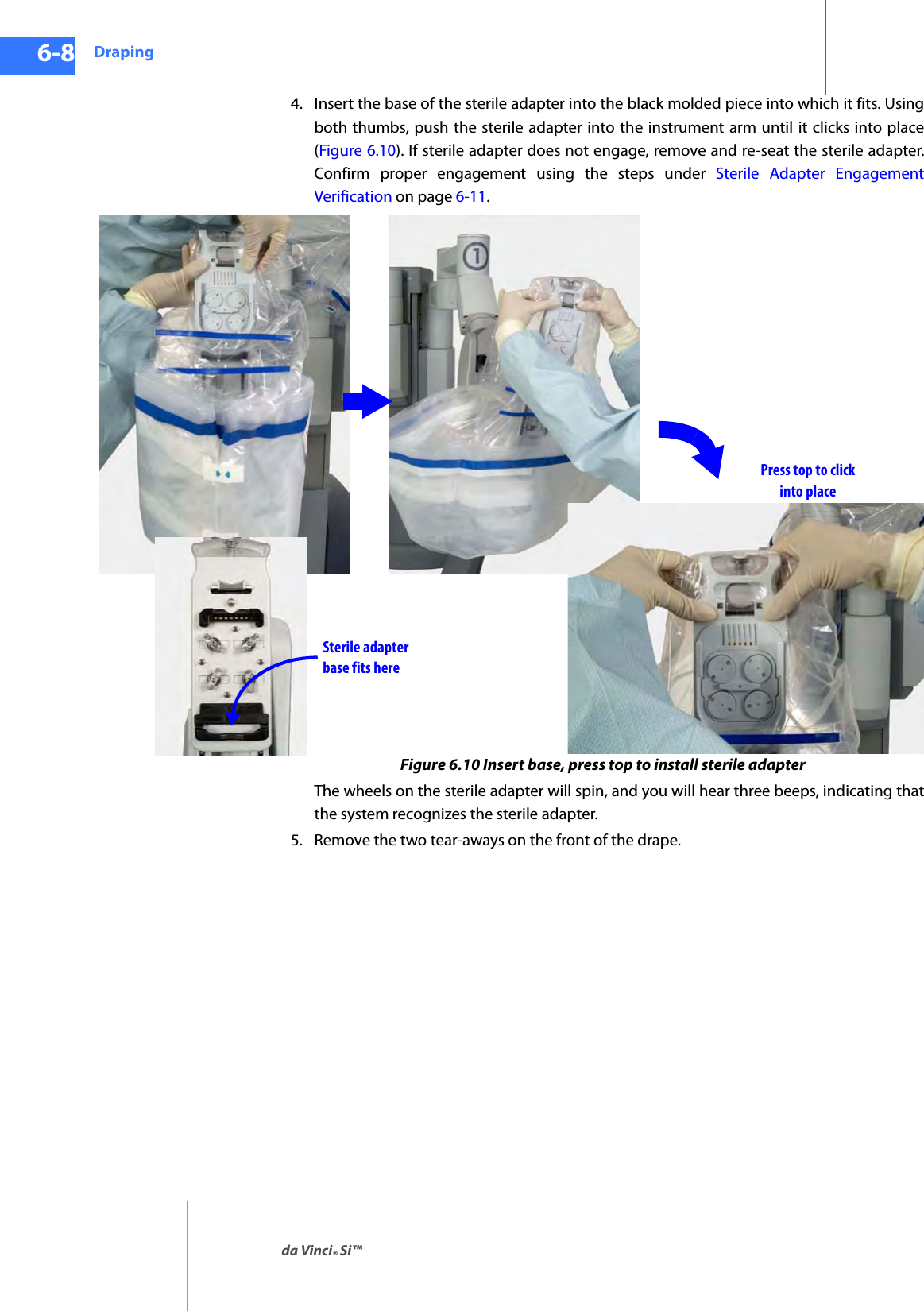
- 2. User Manual Part 2
- 3. User Manual Part 3
- 4. User Manual Part 4
User Manual Part 1
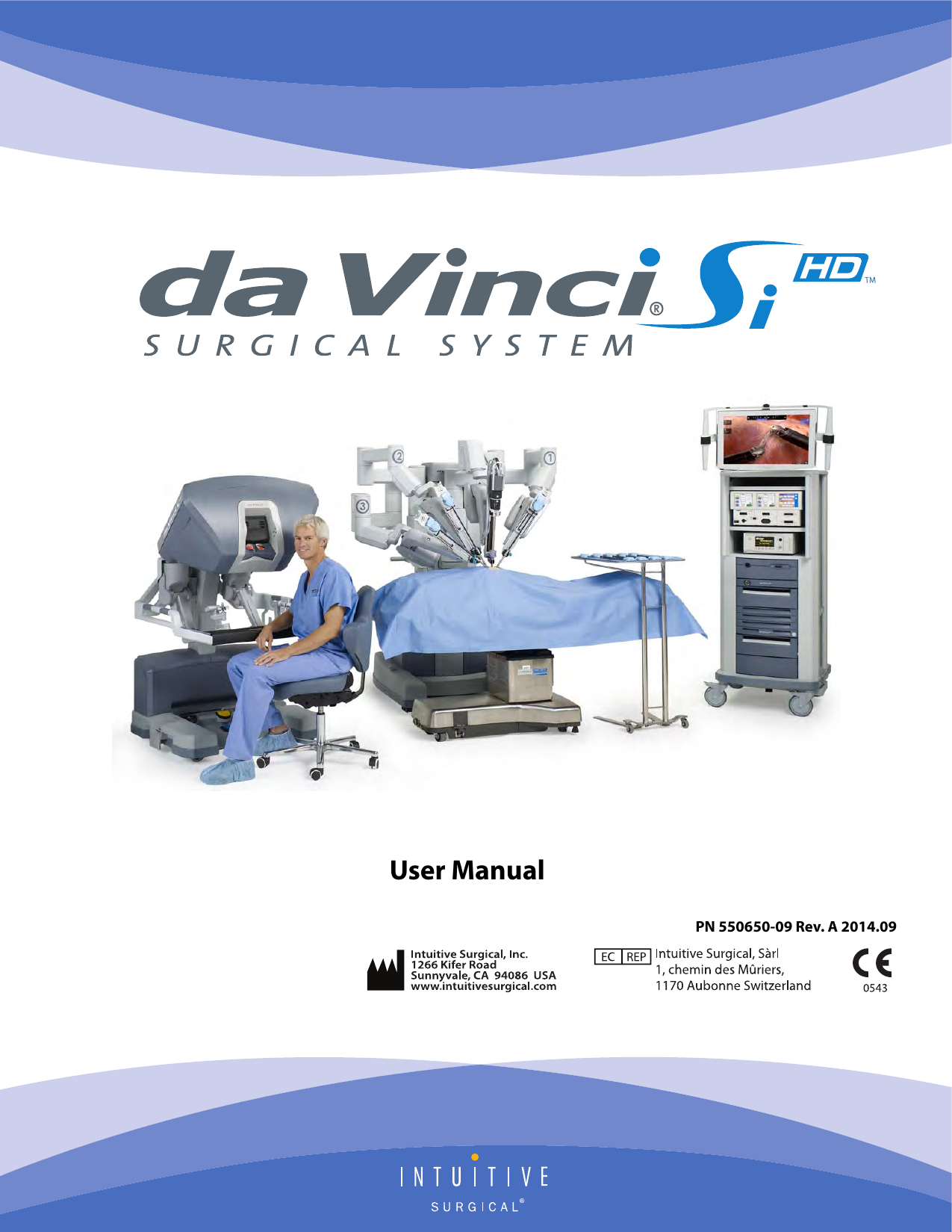


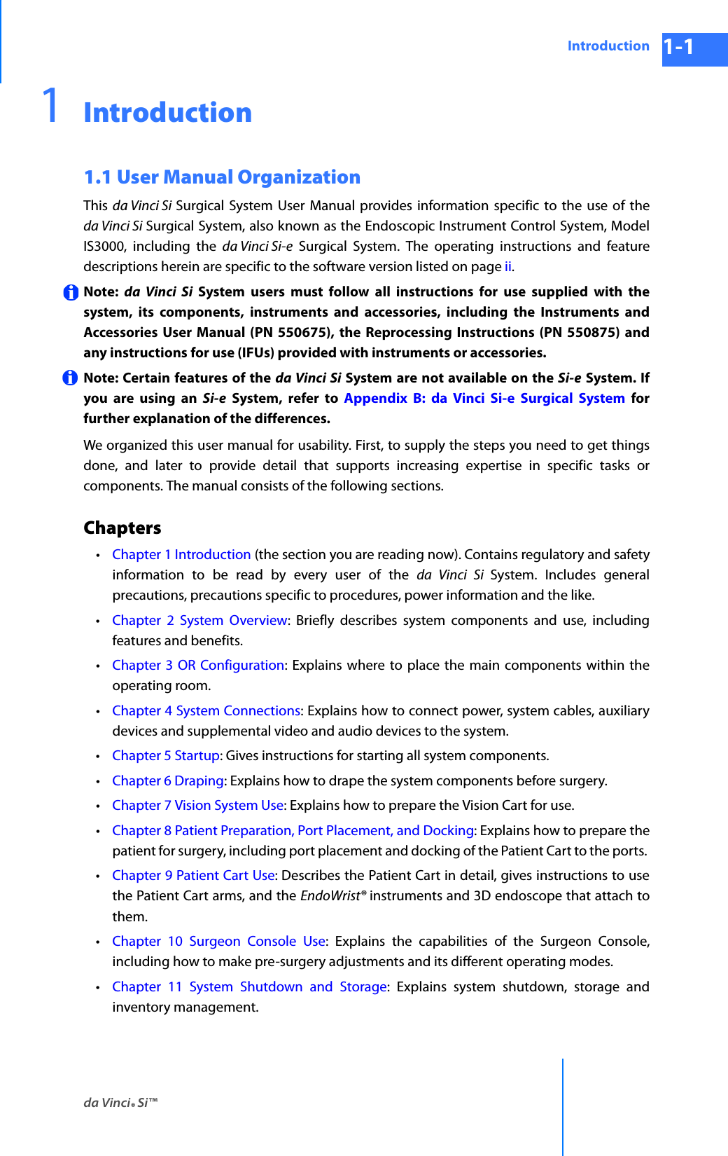

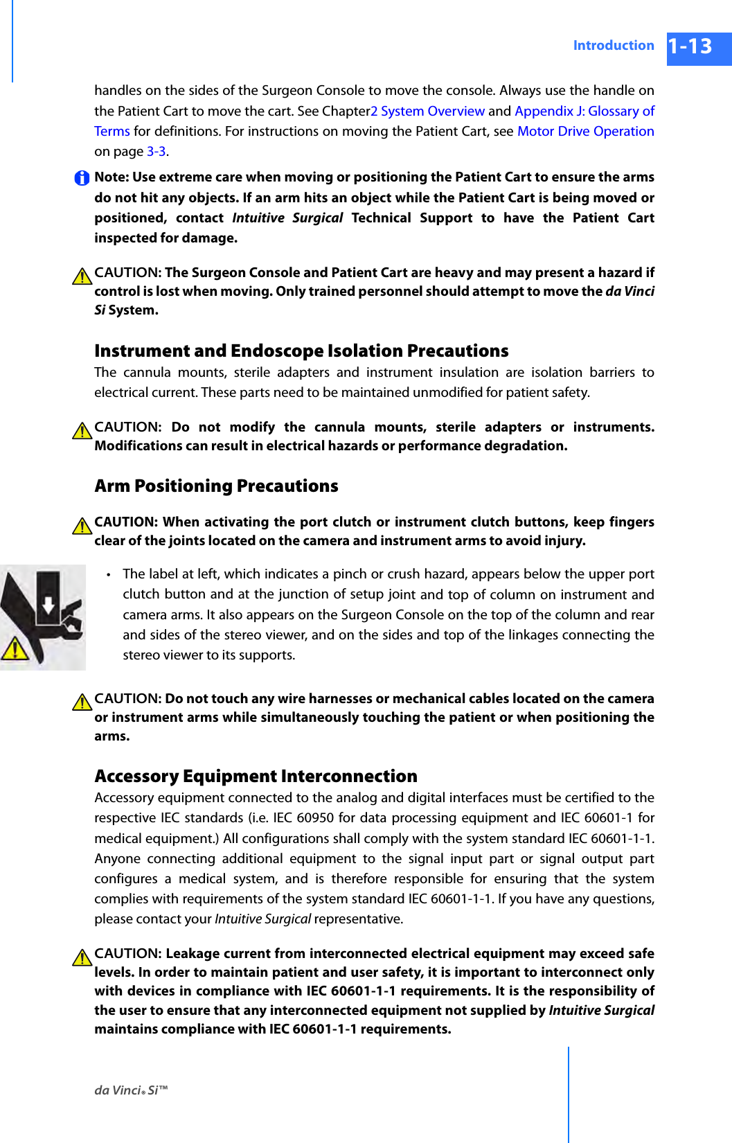
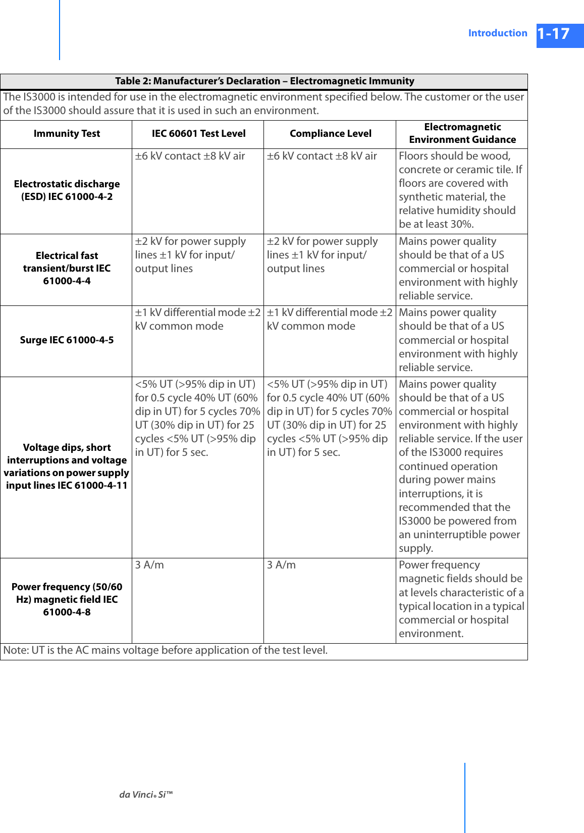
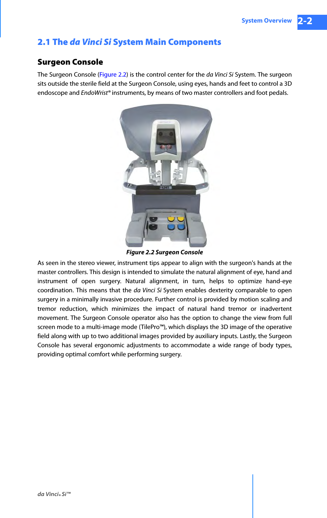
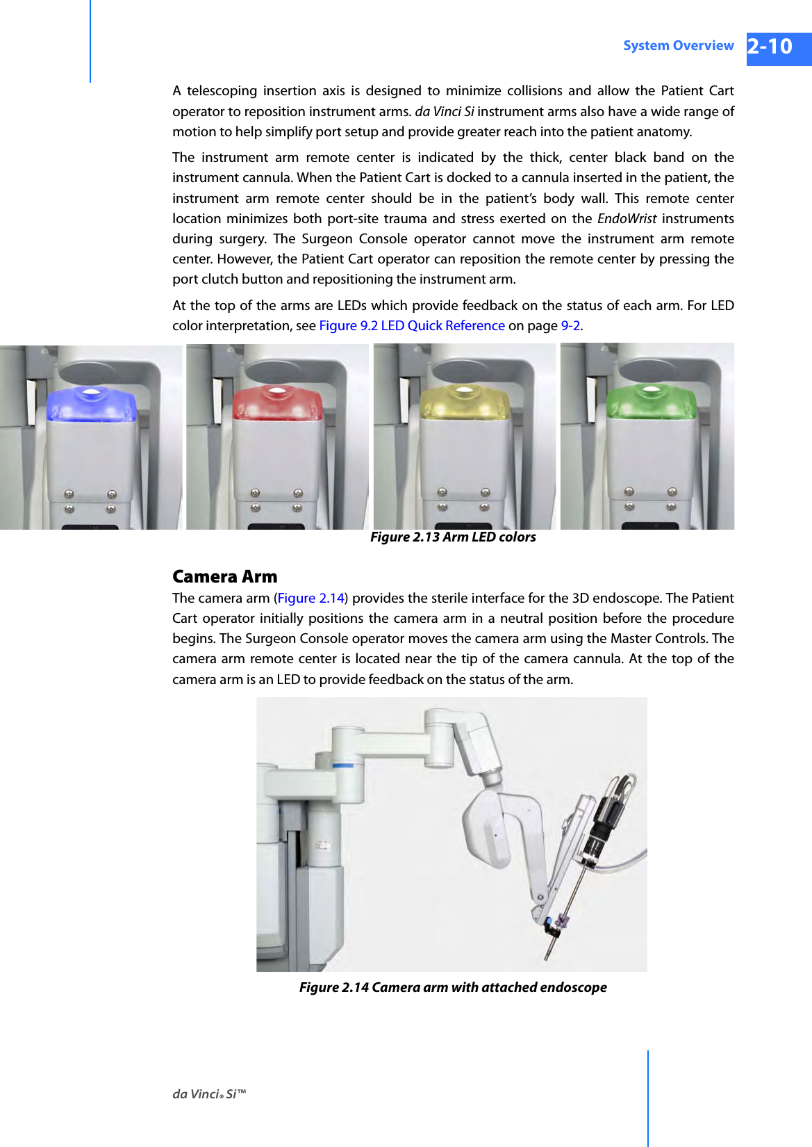
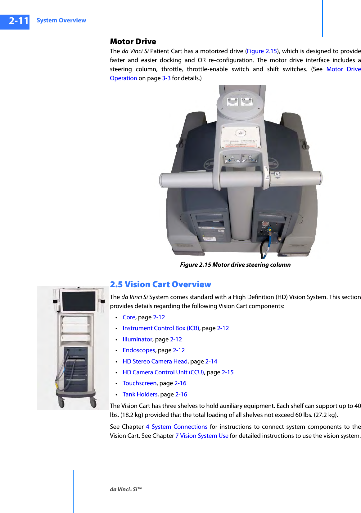
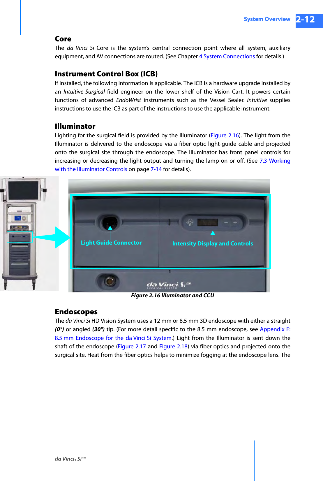
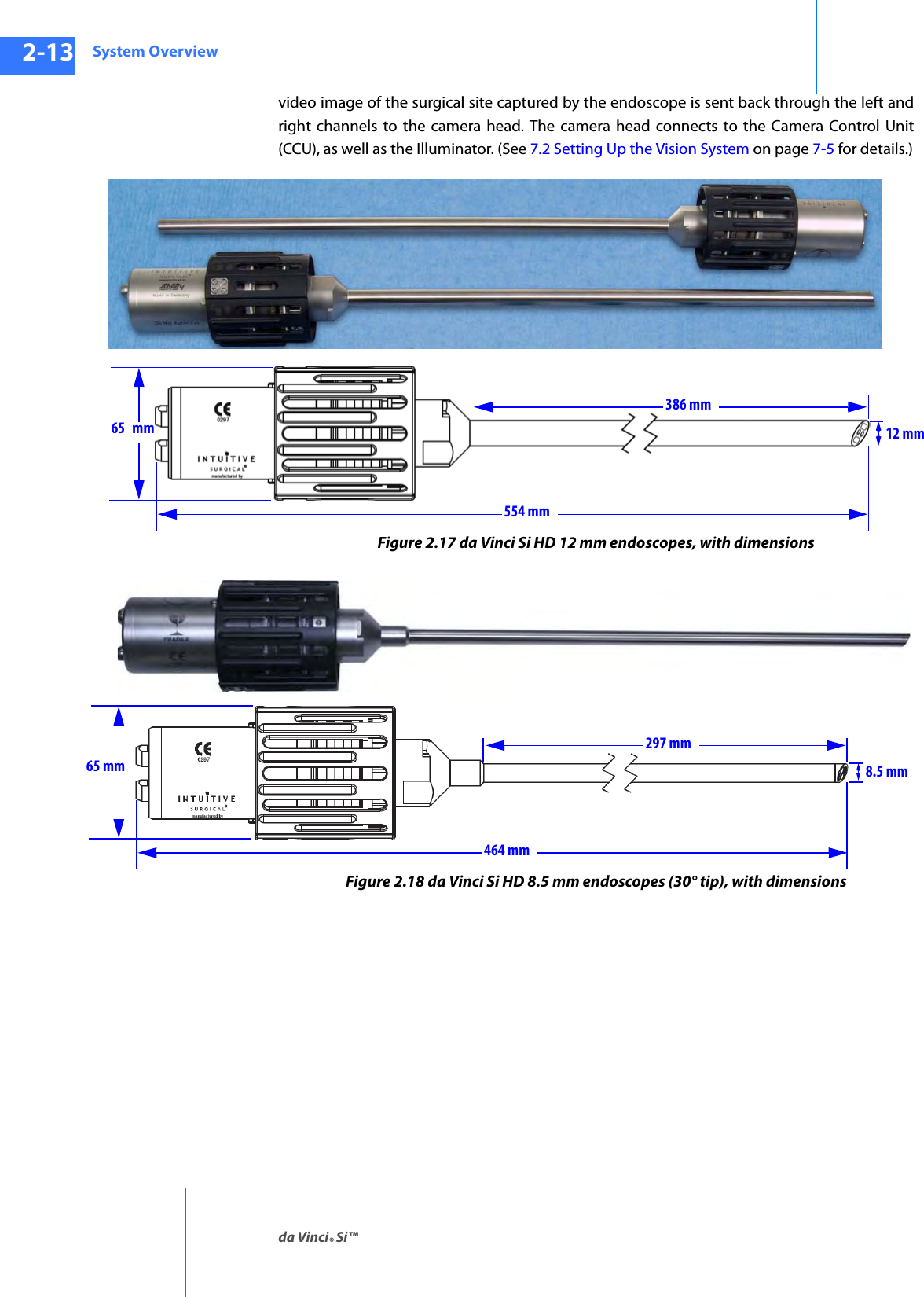
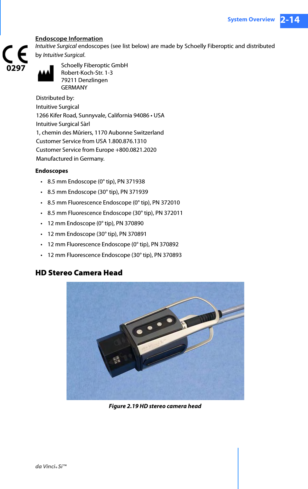
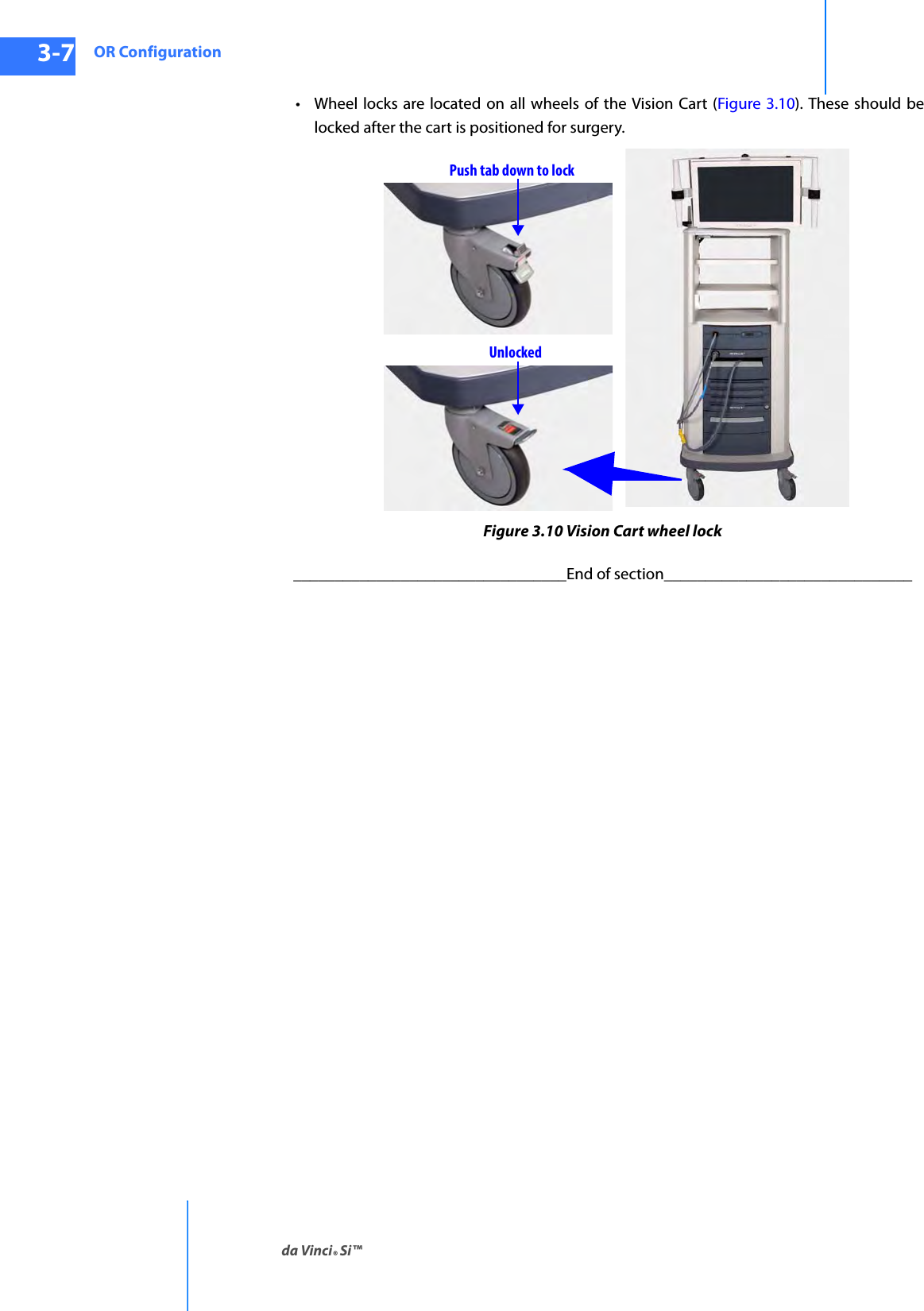
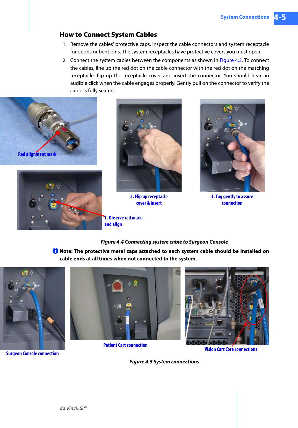
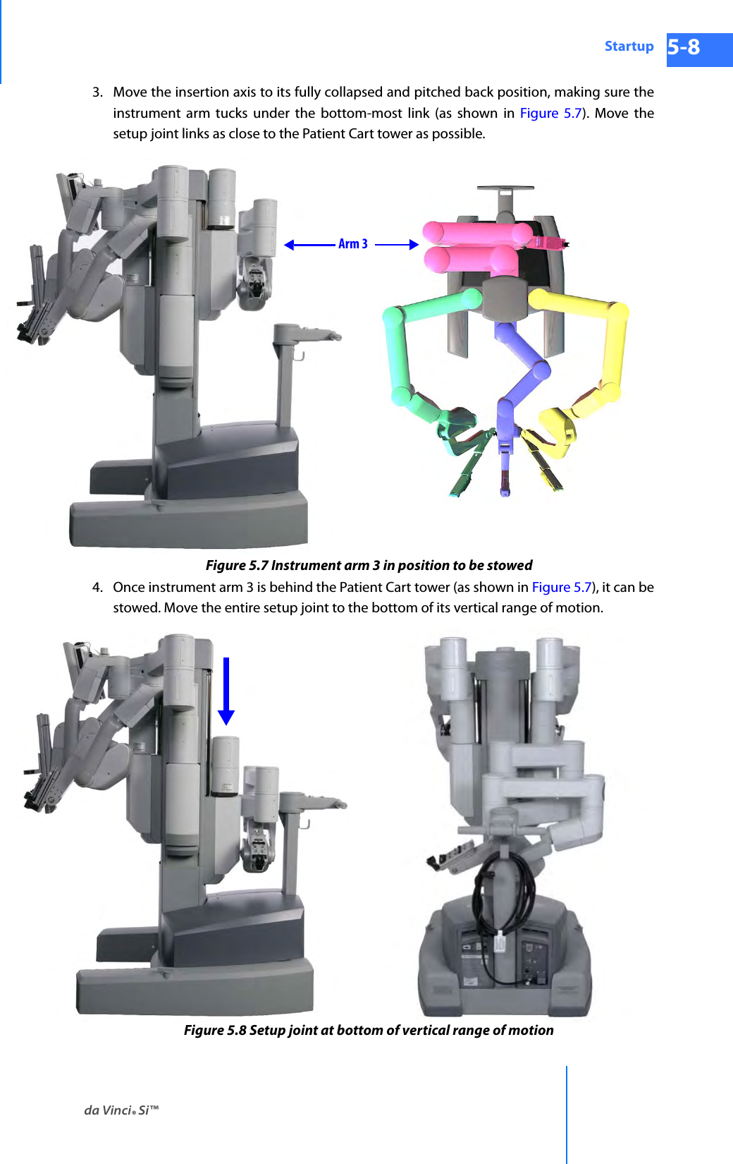
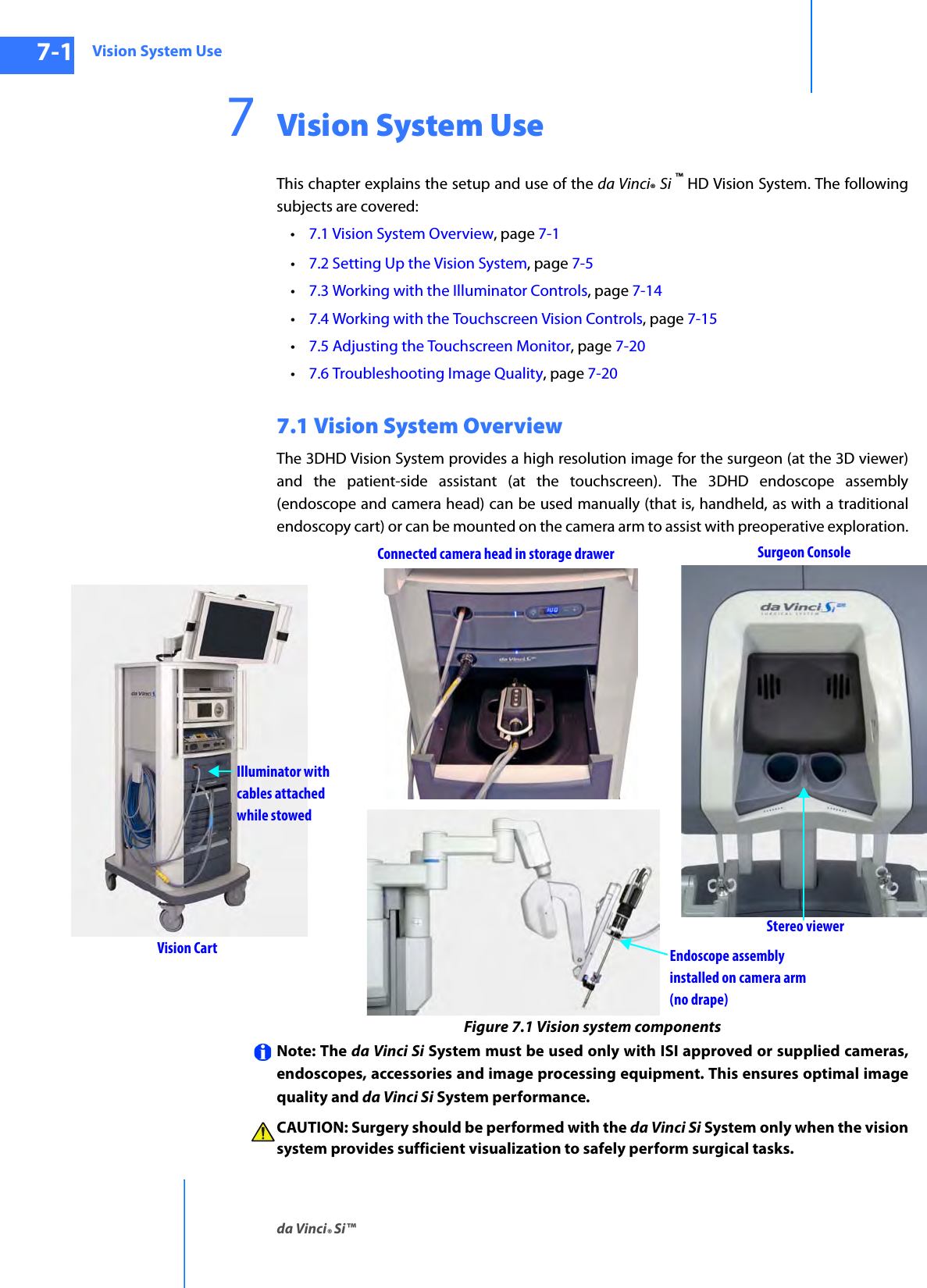
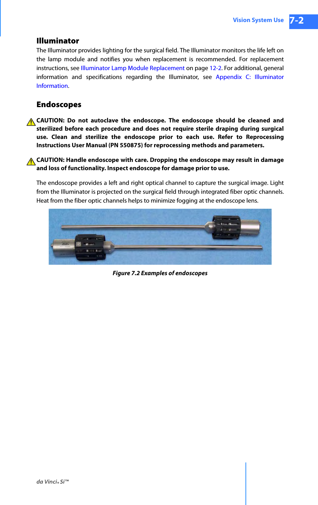
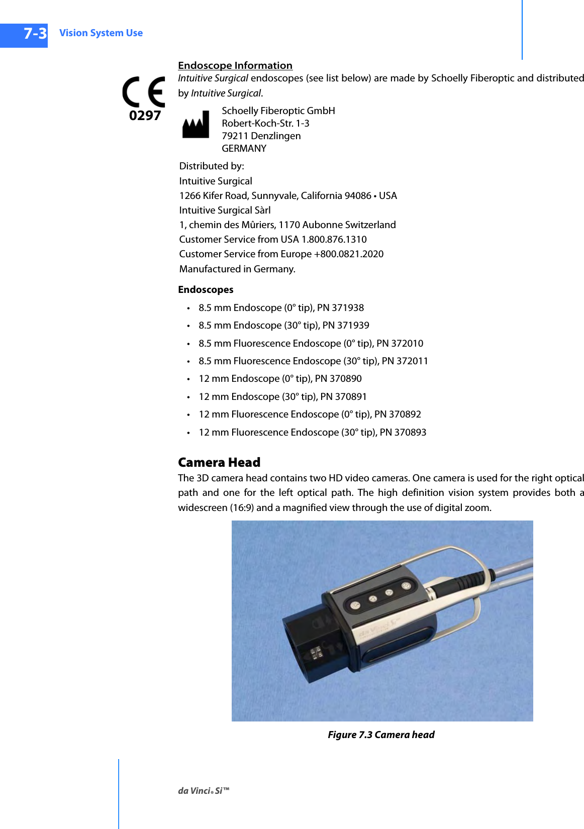
![System Overviewda Vinci® Si™2-15DRAFT/PRE-RELEASE/CONFIDENTIAL10/9/14The HD stereo camera head is designed with a 60-degree field-of-view (FOV). When combined with an Intuitive Surgical stereo endoscope, the vision system provides 6-10x magnification of what is seen during open surgery (without loupes). (See 7.2 Setting Up the Vision System on page 7-5 for details.)Camera Head InformationIntuitive Surgical camera heads [Camera Head Assembly, PN 655859 (371952) and Camera Head Assembly, PN 655858 (372126)] are made by Schoelly Fiberoptic and distributed by Intuitive Surgical.HD Camera Control Unit (CCU)The CCU is connected to the camera by a single cable. The CCU controls the acquisition and processing of the image from the camera.Figure 2.20 Camera Control Unit and IlluminatorSchoelly Fiberoptic GmbH Robert-Koch-Str. 1-3 79211 Denzlingen GERMANYDistributed by:Intuitive Surgical1266 Kifer Road, Sunnyvale, California 94086 • USAIntuitive Surgical Sàrl1, chemin des Mûriers, 1170 Aubonne SwitzerlandCustomer Service from USA 1.800.876.1310Customer Service from Europe +800.0821.2020Manufactured in Germany.Camera cable connector](https://usermanual.wiki/Intuitive-Surgical/CHB01.User-Manual-Part-1/User-Guide-2607924-Page-46.png)
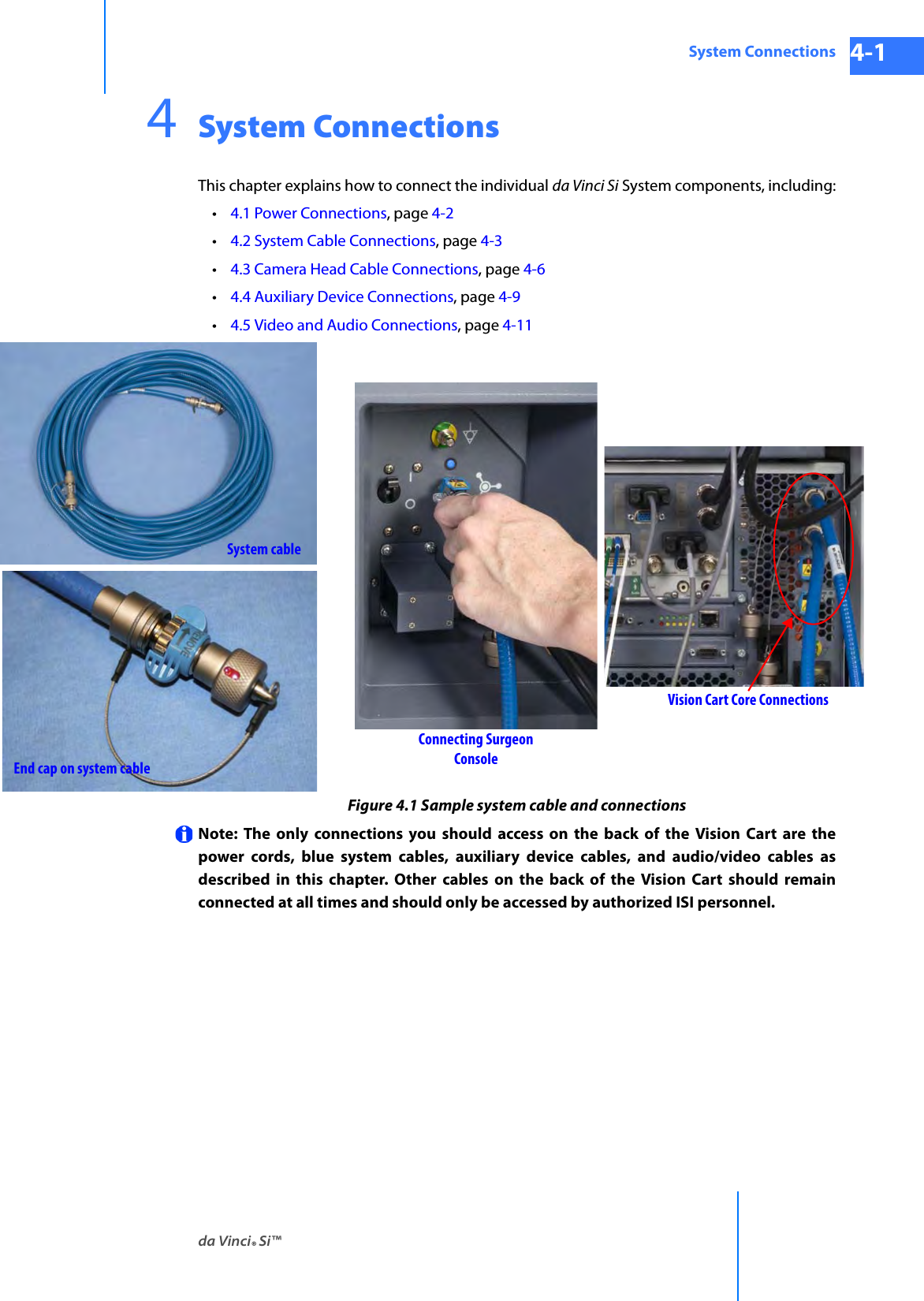
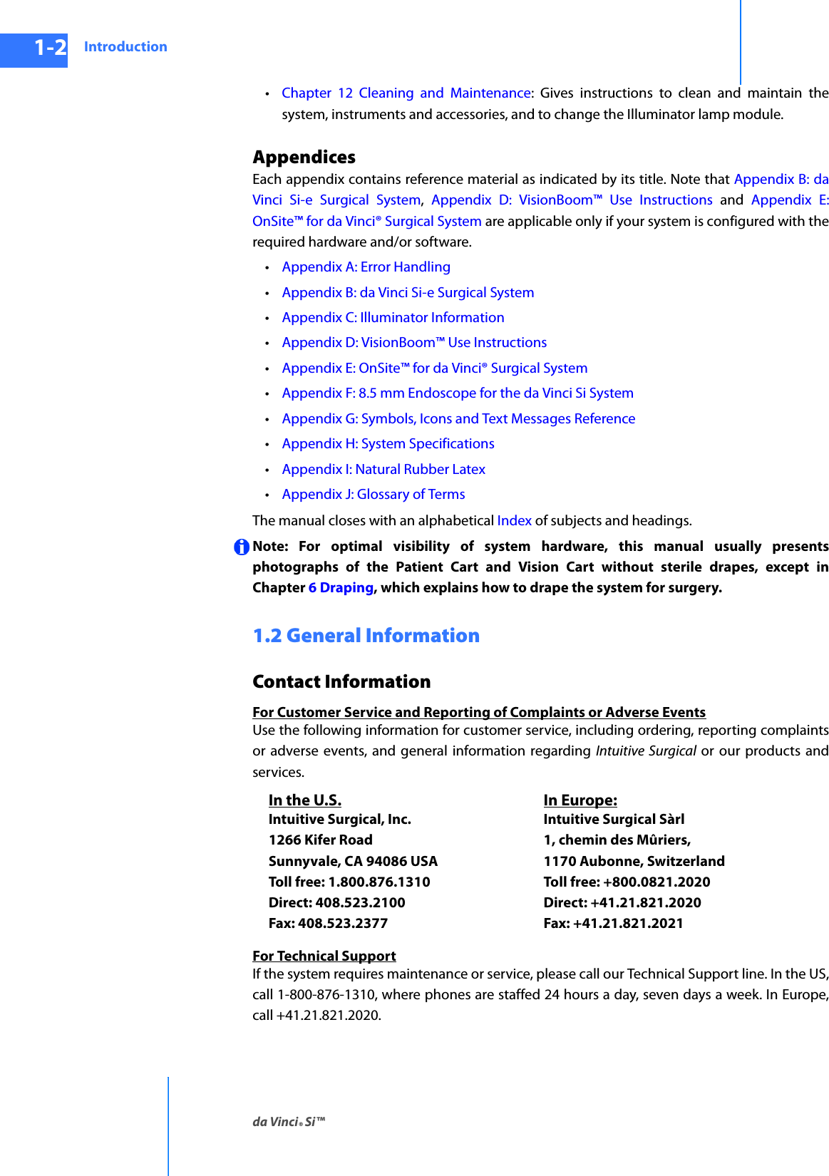
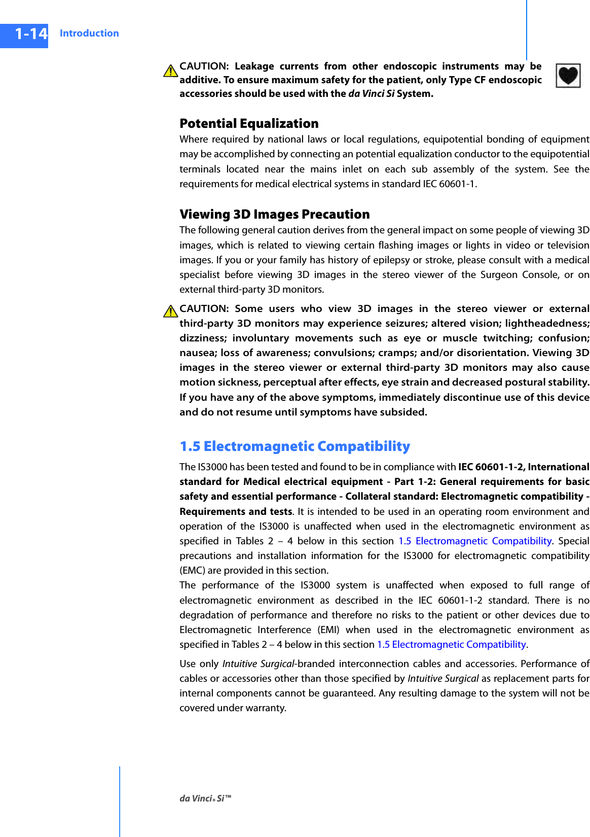
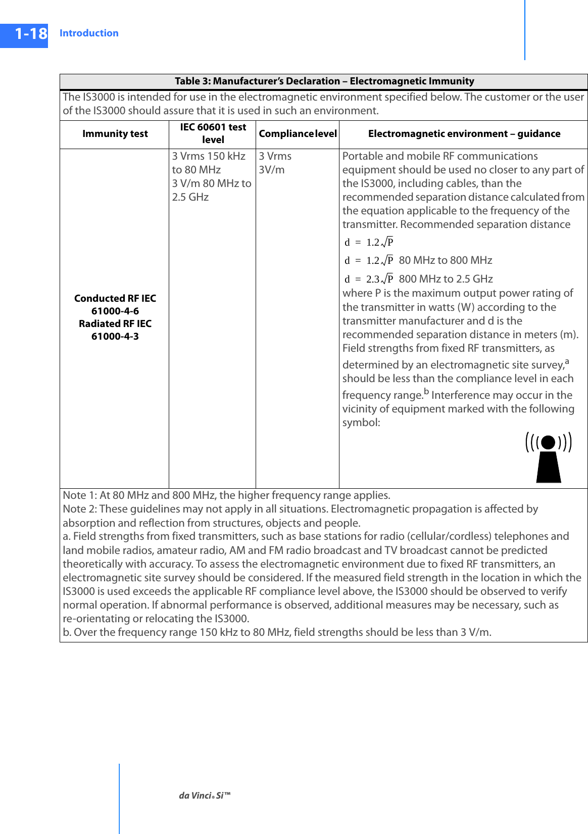
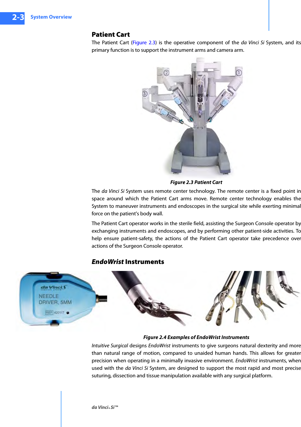
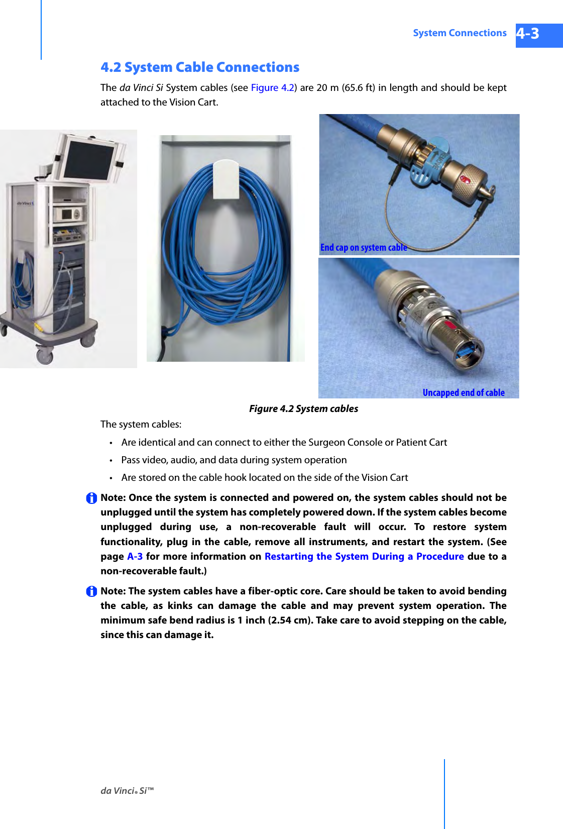
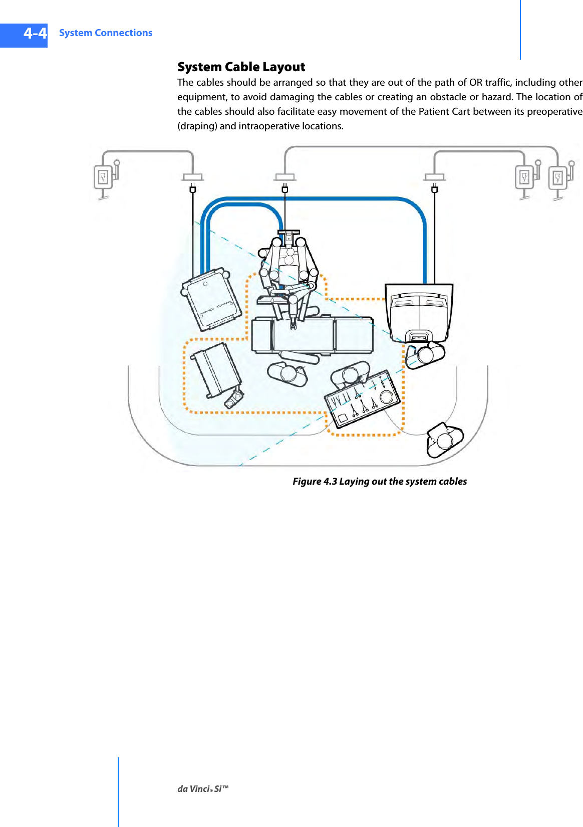
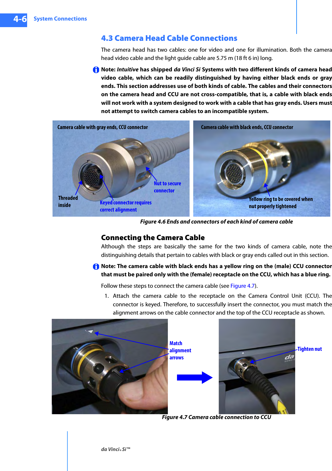
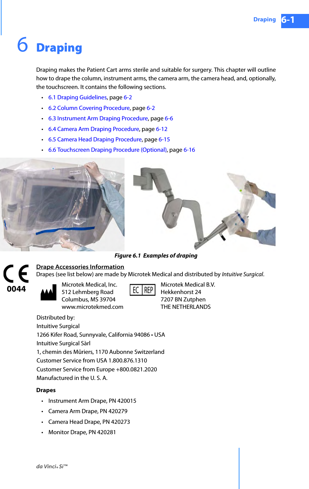
![System Connectionsda Vinci® Si™4-2DRAFT/PRE-RELEASE/CONFIDENTIAL10/9/144.1 Power ConnectionsConnect the AC power cords of the Surgeon Console, Patient Cart, and Vision Cart to wall outlets. (To support continued use of the da Vinci System in case of a site power failure, use wall outlets [often red] supported by backup power.) Ensure adequate power is available at each wall outlet according to the table below:Note: Before first use, connect the Patient Cart to a wall outlet for at least 14 hours to allow the backup battery to fully charge. Note: The Patient Cart should remain plugged in when not in use to ensure that the backup battery stays fully charged.Note: Cooling fans on the Patient Cart and the Core (Vision Cart) run continually when either is plugged into AC. This is part of normal operation. Note: The power cord plug of each cart provides isolation from the supply mains. Position equipment so that the power cord plugs can be accessed to isolate mains power from the system. CAUTION: Do not use an extension cord with any of the system components. Table 4-1 System Power Cords and Power RequirementsSystem Component Cord Length Power Requirement Standby Power DrawSurgeon Console15 ft/4.6 meters 1000VA Continuous8.4A at 115V~4.2A at 230V~95VA0.8A at 115V~0.4A at 230V~Patient Cart15 ft/4.6 meters 1000VA Continuous8.4A at 115V~4.2A at 230V~75VA0.6A at 115V~0.3A at 230V~Vision Cart15 ft/4.6 meters 1500VA Continuous12A at 115V~6A at 230V~145VA1.1A at 115V~0.55A at 230V~](https://usermanual.wiki/Intuitive-Surgical/CHB01.User-Manual-Part-1/User-Guide-2607924-Page-56.png)
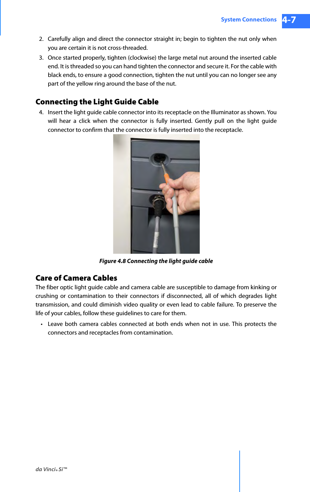
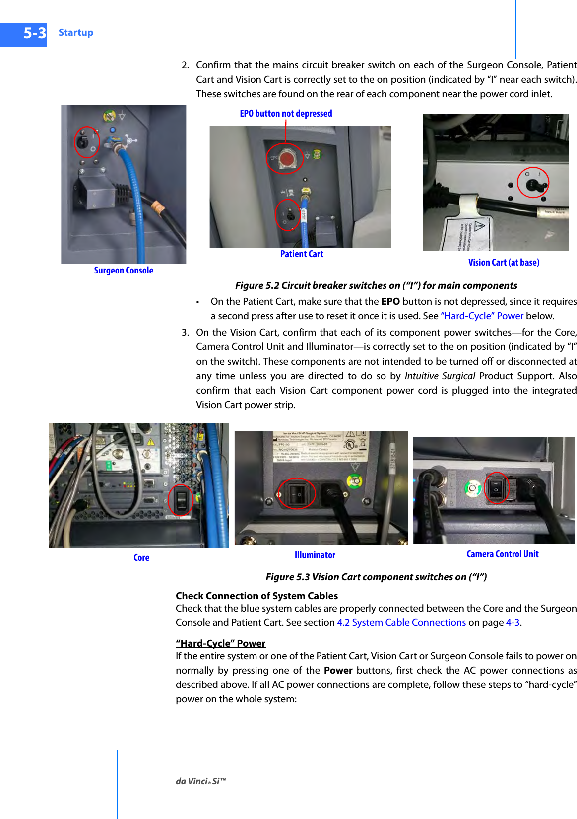

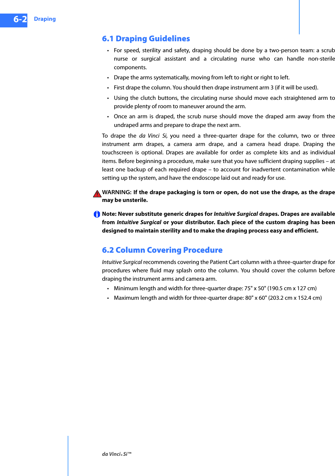
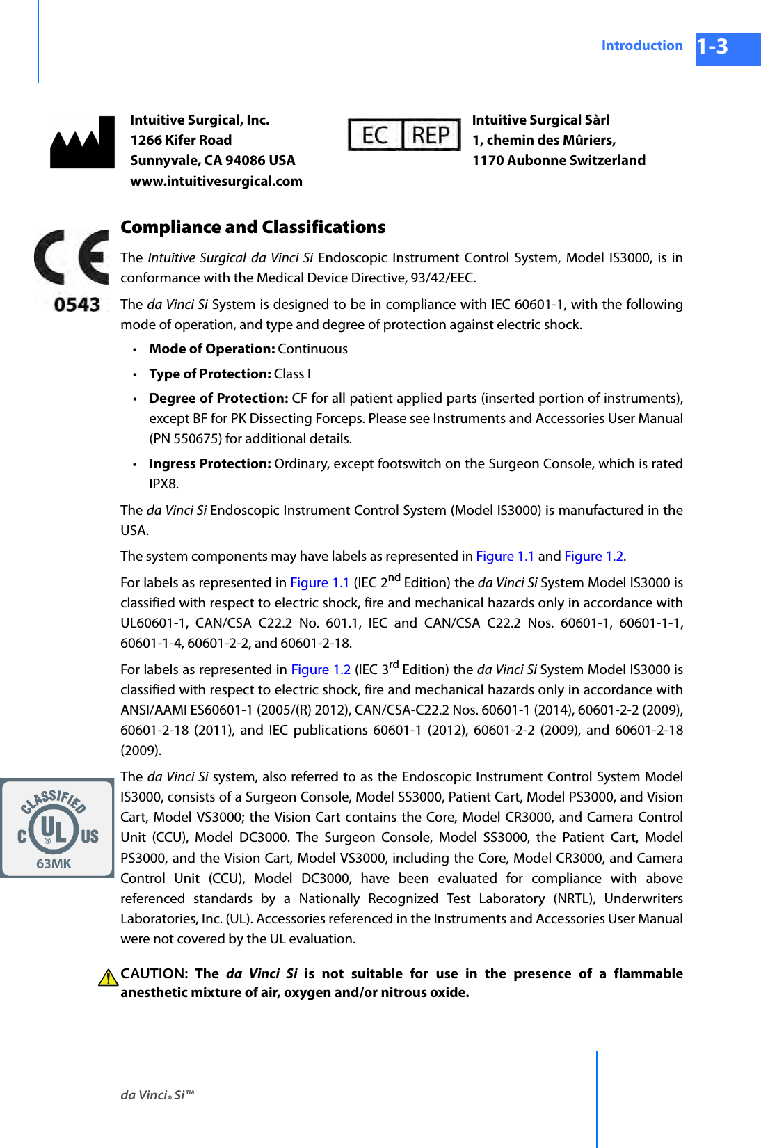
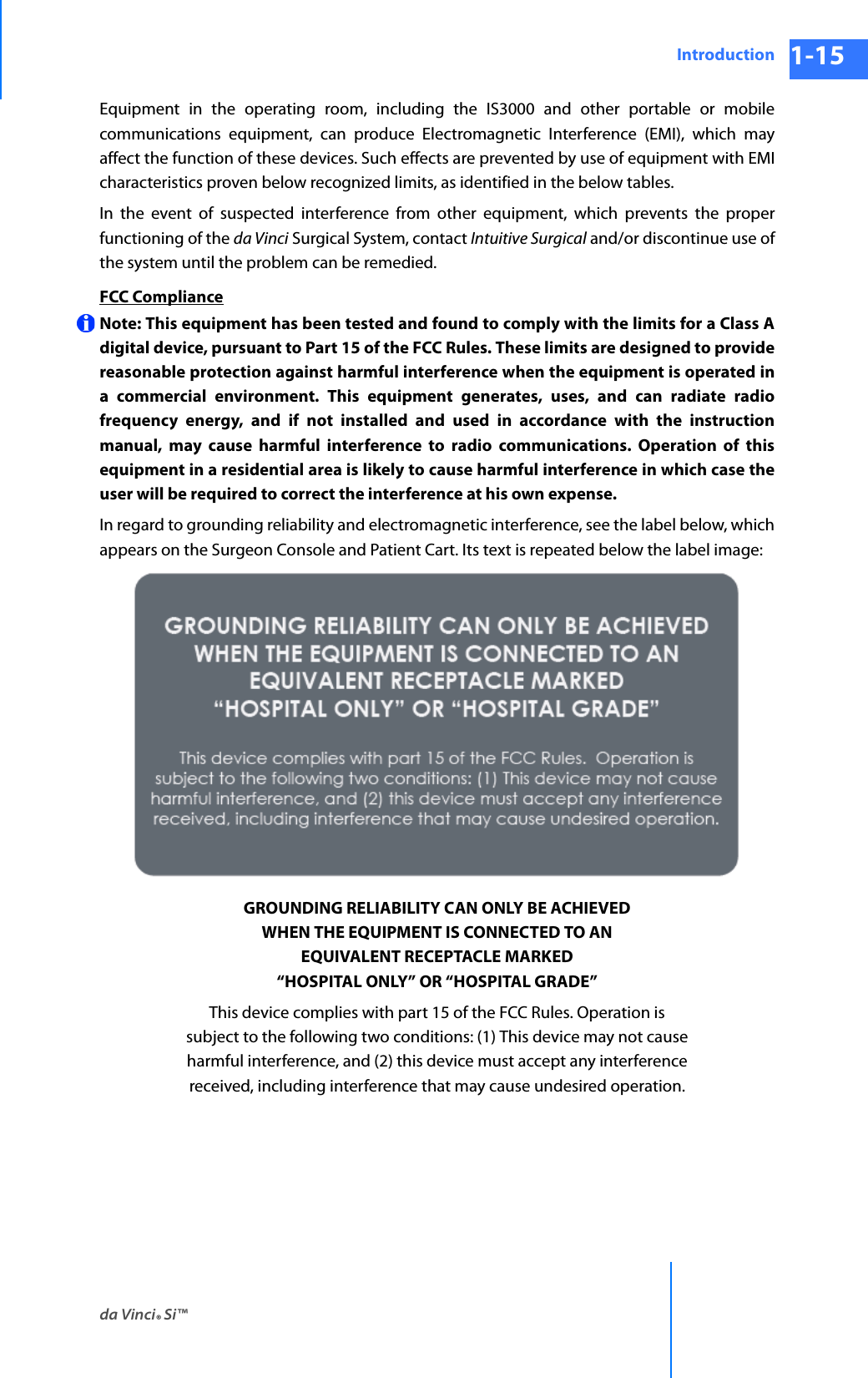
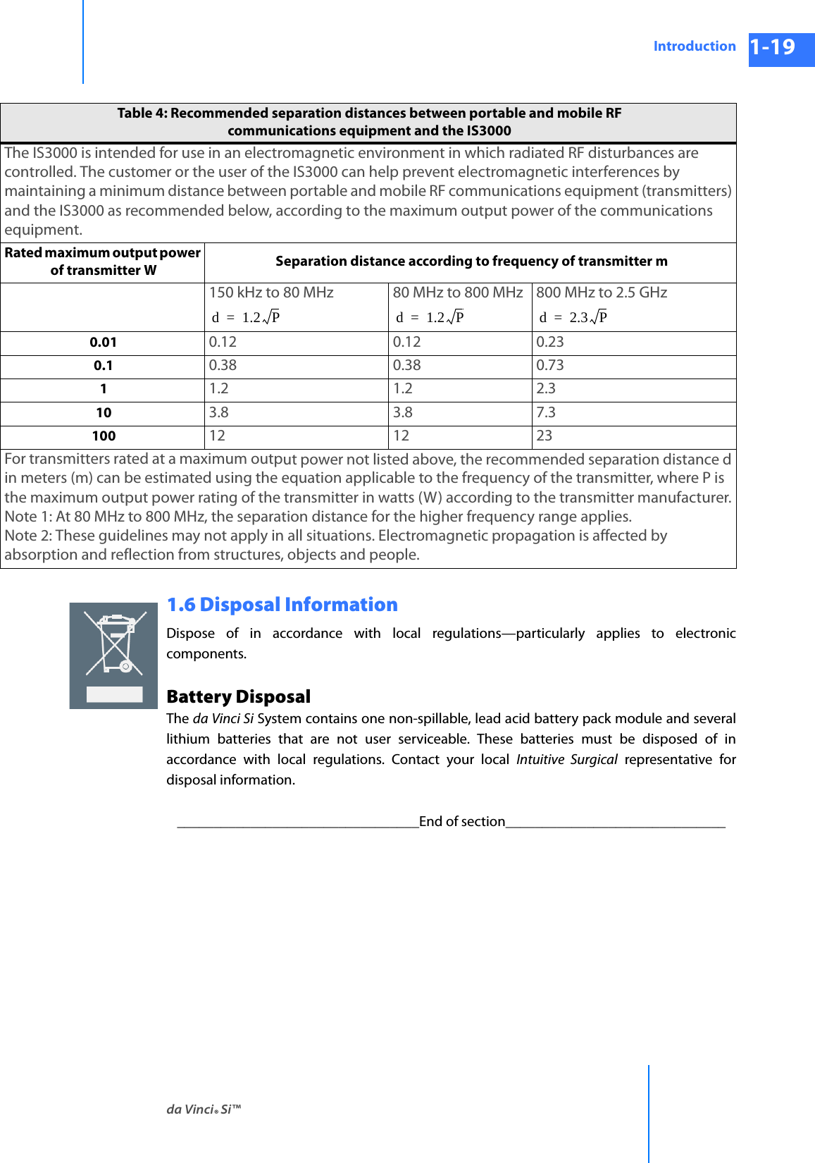
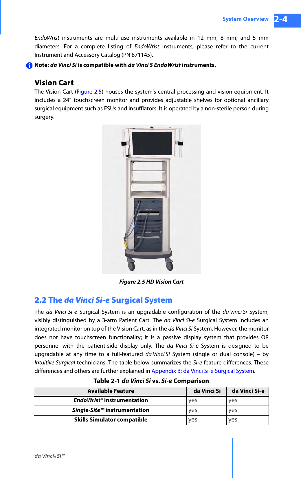
![da Vinci® Si™Vision System Use 7-4DRAFT/PRE-RELEASE/CONFIDENTIAL 10/9/14CAUTION: Handle the camera head carefully. Dropping the camera head may result in damage and loss of camera functionality.Note: Damage to the camera cable can occur through repetitive actions during use in surgical procedures. These failures usually occur near the camera head. CAUTION: Handle the light guide cable carefully. If the cable is bent sharply or kinked, it can damage the fiber optic material enclosed in the light guide cable. Such damage can substantially reduce the amount of light transmitted through the light guide cable (Figure 7.4). Figure 7.4 Examples of mishandling camera head cablesCamera Head InformationIntuitive Surgical camera heads [Camera Head Assembly, PN 655859 (371952) and Camera Head Assembly, PN 655858 (372126)] are made by Schoelly Fiberoptic and distributed by Intuitive Surgical.Touchscreen MonitorThe touchscreen enables you to view and telestrate on the surgical field (and/or optional video inputs), and to adjust vision and system settings. A microphone and speaker on the touchscreen facilitate communication between the surgeon and the patient-side assistant.Schoelly Fiberoptic GmbH Robert-Koch-Str. 1-3 79211 Denzlingen GERMANYDistributed by:Intuitive Surgical1266 Kifer Road, Sunnyvale, California 94086 • USAIntuitive Surgical Sàrl1, chemin des Mûriers, 1170 Aubonne SwitzerlandCustomer Service from USA 1.800.876.1310Customer Service from Europe +800.0821.2020Manufactured in Germany.](https://usermanual.wiki/Intuitive-Surgical/CHB01.User-Manual-Part-1/User-Guide-2607924-Page-99.png)